

Bio-Rad Aminex Organic Acid and Alcohol Analysis Columns User Manual

Guidelines for Use
®
and Care of Aminex
Resin-Based Columns
Instruction Manual
For technical service call your local Bio-Rad office or in the
U.S. Call 1-800-4BIORAD (1-800-424-6723)

Table of Contents
Section 1 Introduction to Resin-Based HPLC Columns ....1
Section 2 Column Set-Up ................................................2
2.1 Unpacking ..................................................................2
2.2 Preparing the Eluant ....................................................2
Section 3 Guard Columns ................................................2
3.1 Installing Guard Columns ............................................3
3.2 Purging the Guard Columns ........................................3
Section 4 Attaching the Column ......................................4
Section 5 Operating Parameters ......................................5
5.1 Flow Rate ....................................................................5
5.2 Sample Preparation ....................................................6
5.3 Pressure Checks ........................................................6
5.4 Column Testing............................................................7
Section 6 Regeneration Procedures ..............................14
6.1 Fluffing the Resin Bed ................................................14
6.2 Cleaning a Contaminated Column..............................14
6.3 Reconverting a Column to its Original Ionic Form ......15
6.4 Topping Off a Column Bed ........................................15
6.5 Rectifying Instrument/Connecting Tubing Problems ..16
Section 7 Heated Column Shut-Down ............................16
Section 8 Column Storage ..............................................17
8.1 Long Term Storage....................................................17
8.2 Short Term Storage ..................................................17
Section 9 Troubleshooting..............................................17

Section 1
Introduction to Resin-Based HPLC Columns
Resin-based HPLC columns use the mechanisms of ion exclusion, ion exchange,
ligand exchange, size exclusion, reversed phase, and normal phase partitioning.
These multiple modes of interaction offer a unique ability to separate compounds.
The charge on the resin provides the capability for ion exclusion, while the
polystyrene backbone allows hydrophobic interaction to take place. The extent of
the interactions depends on the compounds being analyzed and the degree of
selectivity required.
Reversed phase and ion pairing HPLC techniques require complex eluant conditions
for effective separations. These methods work on the principle of modifying the
compound to be analyzed until it is compatible with the column. With resin-based
HPLC columns, instead of modifying the compound to be analyzed, the column
packing material is modified and chromatographic conditions are optimized to be
compatible with the compound structure. Therefore, resin-based columns often allow
the use of an isocratic HPLC system, they simplify sample preparation methods, and
they require no sample derivatization. By cutting down sample preparation time,
resin-based columns greatly reduce total analysis time. Filtration is the only sample
preparation necessary in most separations.
The column is the heart of the high performance liquid chromatographic system.
The success or failure of the analysis often depends on selecting proper operating
conditions and on maintenance of the column. No matter how good the HPLC
system performance and the sample preparation are, successful separations may
not result if the column is not functioning properly.
The packed bed is a depth filter, and thus it is an excellent collection device for
particulate matter. The smaller the packing media, the better it acts as a filter. The
bonded resin column packings are suitable for separating certain solutes, but are also
capable of retaining other components of the sample indefinitely. These retained
compounds may significantly decrease column efficiency and selectivity. If proper care of
the column is not taken, then time and money are wasted, since a good column may be
ruined in a short amount of time. It is extremely important to take the time required to do
any column maintenance which will keep problems to a minimum. With the proper
set-up, proper maintenance, and good laboratory technique, the column will not lose
1

efficiency. This guide for the care of resin-based columns will help to provide higher
resolution, longer column life, and better reproducibility.
Section 2
Column Set-Up
2.1 Unpacking
While unpacking the column, check it carefully for evidence of shipping damage, rough
handling, or leaking solvent. Save the shipping container to store the column. If there is
evidence of damage, immediately notify the carrier and contact Bio-Rad Technical
Service at 1-800-4BIORAD, or your local Bio-Rad office.
2.2 Preparing the Eluant
Only fresh distilled deionized water, analytical grade reagents, and high quality
organic solvents should be used for eluant preparation. The prepared eluant should
be filtered through a 0.45 µm filter before use, to eliminate insoluble particles which
could clog the system inlet filter. Poor baseline stability is often caused by dirty
mobile phase. Thoroughly degas the prepared eluant prior to use.
The best method for degassing solvent is a method which uses both vacuum and
ultrasonics. Vacuum degassing alone will work, but requires a longer time. A
stirring bar in the vacuum flask helps to facilitate the release of gas from the
solvent. Filtering alone will not remove all the gas. The flask used to degas the
solvent could also be used as the reservoir. A 1 liter vacuum filtering flask works
well. Pouring degassed solvent into another reservoir will only add gas to the
eluant. Switching between aqueous and organic solvents is especially likely to
cause outgassing. Be sure that both solvents are thoroughly degassed.
Section 3
Guard Columns
Guard columns have been an accepted part of HPLC technology for a number of
years because of the role they play in protecting both the analytical column and the
HPLC system. Micro-Guard
column, but also provide a convenient method for in-line sample preparation.
Contaminants which interfere with analytical separations, as well as compounds
which foul the analytical columns, can be removed with these cartridges.
®
cartridges not only extend the lifetime of the analytical
2

Interferences caused by anions, cations, organics, salts, insolubles, and
particulates can be reduced or eliminated using Micro-Guard cartridges.
Micro-Guard cartridges are strongly recommended for use with Bio-Rad’s HPLC
columns.
The Micro-Guard HPLC column protection system consists of a disposable guard
cartridge in a standard guard cartridge holder, or an anion and a cation cartridge in
a double deashing holder. The deashing holder is used with the Aminex HPX-42A
silver form column. The deashing format can also be used with other columns
which use water as a mobile phase.
The guard column must be replaced before contamination extends to the main
column. The replacement frequency cannot be standardized, since it depends on
sample preparation conditions. In general, the column should be checked
periodically with a standard sample. When some change in the measured data is
observed, the guard column should be replaced immediately.
3.1 Installing Guard Columns
To install a cartridge, unscrew the end nut from one end of the holder. Attach the
solvent tubing from the injector to the Micro-Guard holder with the Parker-style nut
and ferrule included with each new cartridge holder. While the cartridge may be used
initially in either direction, changing the direction of the used cartridge may cause
particulate matter to flow off the cartridge and contaminate the analytical column.
Attach a short piece of tubing leading from the cartridge holder to the main HPLC
column in a fashion similar to the inlet tubing (see instructions for cartridge holder).
Place the guard column into the holder and secure the holder finger tight, using both
end nuts. Further tightening is unnecessary and may damage the seal or holder.
Never use tools to over tighten this seal.
To store a cartridge out of its holder between uses, protect its Kel-F frit assemblies
from dirt and scratches. Store it in its zip-locking bag, with a few drops of
recommended storage solvent to keep the cartridge from drying out.
3.2 Purging the Guard Column
Flush approximately 10–15 ml of mobile phase through a new guard column at a
flow rate of 0.2–0.3 ml/minute. With resin-based HPLC columns, it is not unusual
to find yellow eluant coming off the column initially for a short period. This material
is polysulfonate formed during column storage. Repeat this procedure each time a
new guard column is installed. The analytical column now may be attached to the
Micro-Guard column.
3

Section 4
Connecting the Column
Reduce the flow rate to 0.2 ml/min. Remove the end screws from the analytical
column and attach the outlet end of the guard column tubing to the inlet of the
analytical column. Connect the analytical column with the pump running at a slow
flow rate, to exclude any air from the column inlet. Pass approximately 20 ml of
degassed solvent through the column. When a new column is initially placed on an
LC system for use or testing, the column should be attached only at the inlet end
when introducing the mobile phase. This prevents particulates of packing (should
the frit have been broken in shipment) or air bubbles (if the column dried during
storage) from getting into the detector flow cell. When clear, bubble-free solvent is
flowing from the outlet end of the column, the column outlet may be attached to
the detector.
It is important that the tubing between the column and the detector be as short as
possible. Tubing with a small inner diameter (0.010 inch ID) should be used
between the injector and the column, and also between the column and detector.
Be sure to make provision for collecting and properly disposing of waste solvent.
Place the column in Bio-Rad’s Column Heater (catalog number 125-0425),
equipped with the appropriate inserts, after checking for leaks in guard column and
analytical column connections. Turn on the column heater and adjust the
temperature. Never heat the column without flow. Increase the flow rate only after
the column has reached the set temperature. Equilibrate the column with your
eluant. With gradient systems, use the starting eluant.
Be sure air does not get into the column. If there is reason to believe that it has,
reduce the column temperature, reverse the column direction, and allow the
solvent to flow slowly through the column until the air is eliminated. Be sure to
remove air from all system piping. Then reconnect the column correctly.
Note that all metal tube connections are of the compression screw (reverse nut)
type. A ferrule is compressed permanently against the tubing. To insure minimum
dead volumes, tighten the assembly of tubing, ferrule, and nut finger tight. Push
the tubing in until it bottoms firmly. Using a 1/4’’ wrench, tighten 1/4 turn. The
fitting only needs to be tight enough to seal; its lifetime will be diminished by
over-tightening.
4
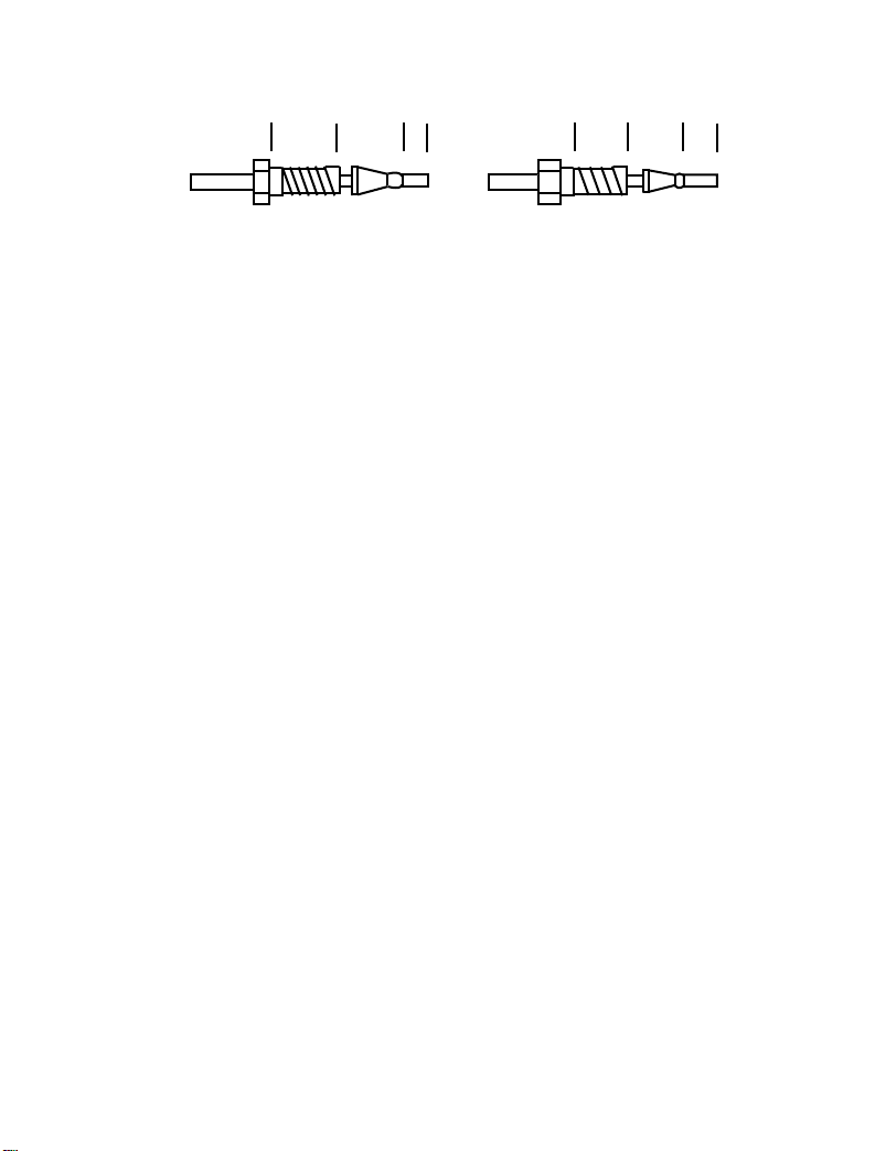
.300” .08” .210” .09”
Valco Parker
Fig. 1. Bio-Rad’s resin-based columns are manufactured using Parker end-fittings. Reverse
nuts and ferrules are supplied with the columns and must be used to attach the column to the HPLC
system if the system is not already equipped with Parker 1/16” reverse nuts or the equivalent.
Section 5
Operating Parameters
At this time the HPLC system should have been purged with priming solvent
followed by the proper mobile phase, the guard column should have been
equilibrated, and the analytical column should be attached. The flow rate should be
at 0.2 ml/min.
5.1 Flow Rate
Ramp up the flow rate slowly on Aminex columns. Increase the flow rate of a
heated column only after the column has come up to operating temperature. Do
not operate high temperature Aminex carbohydrate columns (Aminex HPX-87C,
Aminex HPX-87P, Aminex HPX-87N, or Aminex HPX-87K columns) above
0.3 ml/min while at ambient temperatures. First, allow the column heater to heat
the column while maintaining slower flow rates; then increase to the operating flow
rate when the column has arrived at the recommended operating temperature. Do
not allow the flow rate to exceed the maximum rate specified for the column, but
even then, columns should not be operated at maximum flow rates for extended
periods. Optimum flow rates are specified in published methods, and also flow
rates can be selected based on the quality of the resolution. Many times, slower
flow rates improve resolution. Typically, 300 mm long (30 cm) Aminex columns
operate best at 0.5 to 0.7 ml/min, when back pressure on the column is below
maximum levels. Back pressures may increase with column age, so let back
pressure be the primary determinant of flow rate. Standard flow rate for the Aminex
HPX-87C, Aminex HPX-87H, and other Aminex HPX-87 series columns is
0.6 ml/min.
5
 Loading...