

Page 1
The Display Base can be plugged into the wall using the provided single-head USB cable
(with no connection to the PC), or the Display Base can be plugged into a PC using the
provided cable with two USB heads.
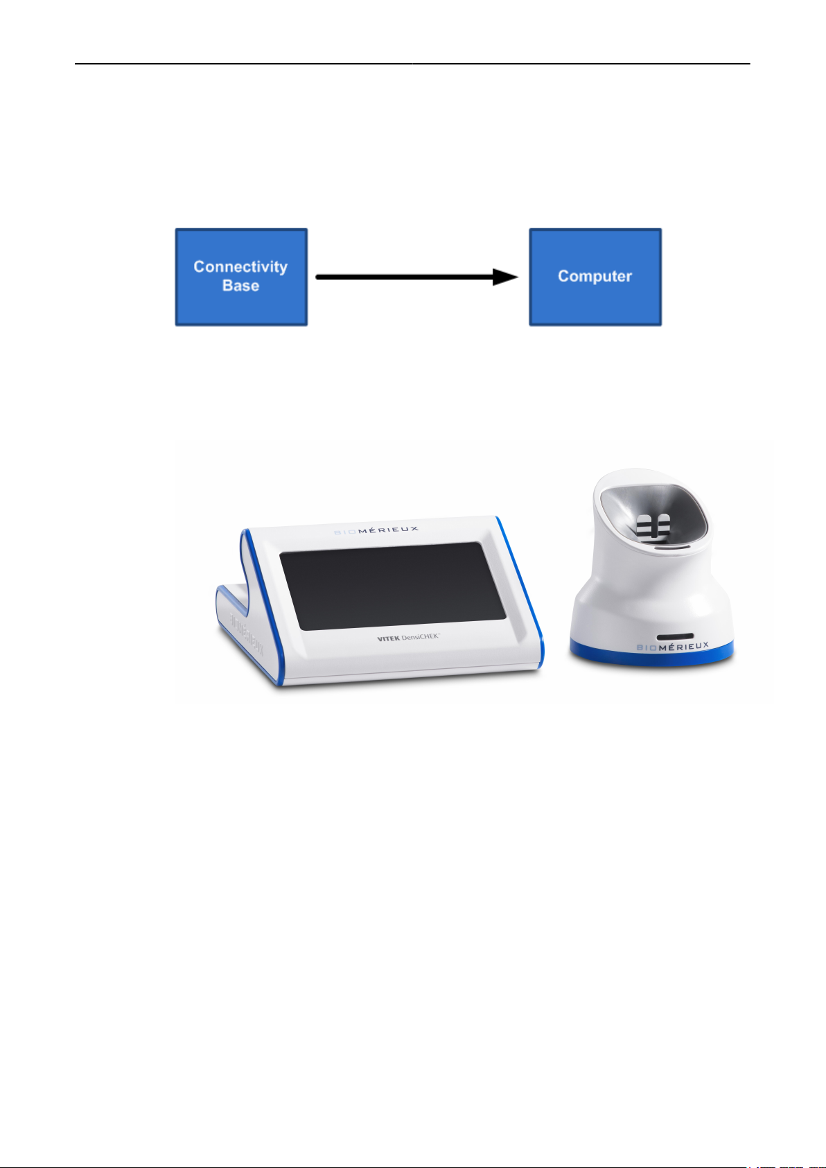
Figure 13: VITEK® DensiCHEK® System Configurations - Connectivity Base
The Connectivity Base must be plugged into a PC.
Overview of Operation Elements
Figure 14: Display Base and Pod Overview
System Description and Basic Operations
Main Components of the VITEK® DensiCHEK® Instrument
• Displau Base or Connectivity Base Unit – Syncs to and charges the Pod.
• Pod - Optically reads the McFarland value of microorganism suspensions for the user and
communicates the value to the base unit.
• McFarland References – Verifies the calibration of the optics contained within the Pod.
These references are dual-vials and labeled 0.0, 0.5, 2.0, and 3.0 McFarland.
Secondary Components of the VITEK® DensiCHEK® Instrument
• 12 mm x 75 mm clear polystyrene test tubes.
• VITEK® 2 software compatible with the DensiCHEK® - Assists with the following tasks:
◦ Tracks individual McFarland values from the Pod.
◦ Communicates between the Pod, the base unit, and a PC. (The Pod communicates via
a Bluetooth wireless connection to the base unit. The base unit communicates to the
PC running VITEK® 2 FLEXprep™ software via a USB wired connection.)
048641-01 3-7 VITEK® DensiCHEK
Page 2

Pod
Pod
System Description and Basic Operations
The Pod optically reads the turbidity of a microorganism suspension and sends the
information to the base unit, so the user has a assessment of the suspension. The Pod is
intended to be used with polystyrene test tubes.
Pod Lights
The Pod has two lights on the front: one for the status of the pairing connection to the base
and one for the McFarland status.
The Pairing Light demonstrates connectivity by:
• A blinking red light or solid colored light that does not match that of the base unit indicates
that the Pod is not synced to the base unit, or it is out of range from the base unit.
• A solid colored light matching that of the base unit indicates that the Pod is synced to the
base unit.
Note: The solid colored light is configured on the Configuration screen by the user. The color
options are cyan, blue, pink, white, green, and yellow.
• No illumination of the light indicates that the Pod is not charged.
• A blinking colored light (excluding red) indicates that the Pod entered Power Save mode. If
you want to exit Power Save mode, insert a test tube into the paired Pod, tap the display
screen, or remove and re-seat the Pod on the base unit. The Pod turns on again.
Note: Power Save mode does not affect connected PCs.
The McFarland Status light demonstrates performance by:
• A green light indicates that the suspension is within the selected card type performance
range.
• A red light indicates that the suspension is above the selected card type performance
range.
• A yellow light indicates that the suspension is below the selected card type performance
range.
• No light indicates that a suspension is being measured with the N/A card selected, that the
pod is in the process of taking a McFarland measurement, or that no measurement is in
progress.
Note: When you have selected the N/A screen, the system does not alert you when a
suspension is in or out of range. N/A provides the McFarland value for suspensions, but it
does not provide an acceptable range.
Pod Button
The Pod has one button on the back of it. If the Pod is paired with a base and a test tube is
inserted, when this button is pressed once, the McFarland value for the current suspension is
captured on the FLEXPrep screen (if configured).
IMPORTANT: After pressing the button on the Pod, the following happens: The saved McFarland
value appears above the main number on the screen.
If the button is held down for approximately three seconds, while a saline tube or 0.0
McFarland reference is inserted, then the instrument is zeroed.
048641-01 3-8 VITEK® DensiCHEK
Page 3
Display Base
System Description and Basic Operations
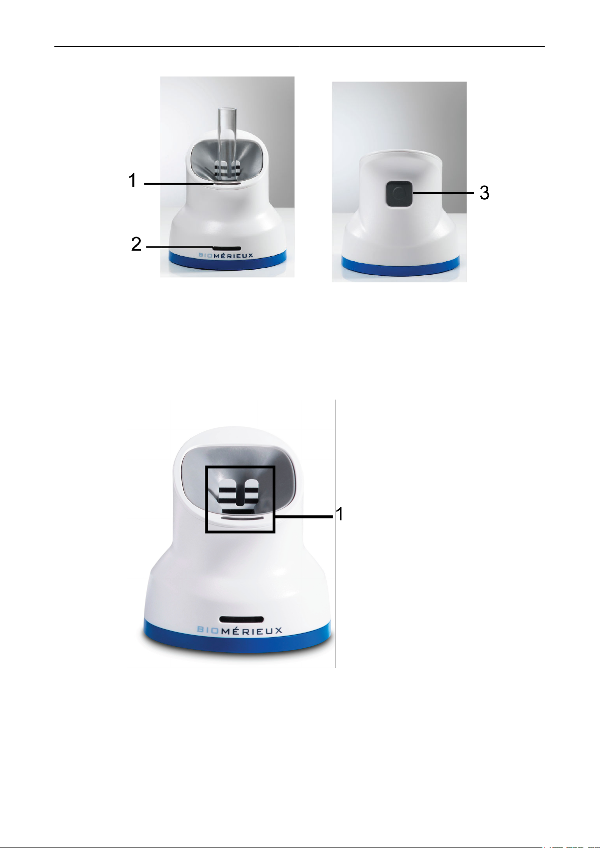
Figure 15: Pod
1. McFarland Status Light
2. Pod Pairing Light
3. Pod Button
A contrast plate is included with the Pod. The contrast plate can be used to aid in assessing
the turbidity of a suspension. This contrast plate cannot be used as an alternative manual
inoculation measurement method.
Figure 16: Contrast Plate Within the Pod
1. Contrast Plate
Display Base
The Display Base syncs to and charges the Pod. This base has a display screen that displays
a McFarland reading measurement of a tube inserted into the Pod. This base can also
transmit information to the VITEK® 2 software compatible with the VITEK® DensiCHEK®, if the
user has access to the software.
048641-01 3-9 VITEK® DensiCHEK
Page 4

Connectivity Base System Description and Basic Operations
When a Pod is synced to a Display Base, the McFarland Status light on the Pod matches the
McFarland Meter color on the display screen. Additionally, the Pod icon color in the corner of
the display screen matches the Pairing Light color on the Pod.
Figure 17: VITEK® DensiCHEK® Display Base with the Pod
1. McFarland Status Light
2. Display Screen
Connectivity Base
The Connectivity Base syncs to and charges the Pod. This base unit does not have a display
screen, so the values are transmitted directly to the VITEK® 2 FLEXprep software.
Both the Display Base and the Connectivity Base work with the Connectivity workflows;
however, the connectivity base does not work with Standalone workflows. To use the
Connectivity Base, you must have the instrument connected to the compatible PC with
VITEK® 2 FLEXprep software using the provided USB cable.
When a Pod is synced to a Connectivity Base, the Pod Pairing Light color matches the Base
Pairing Light color.
WARNING
If the Connectivity Base fails to communicate with the PC, the following
occurs: (1) the McFarland measurement data is not displayed; (2) the
Connectivity Base cannot download software or firmware updates; and (3)
the Connectivity Base cannot send data to the connected VITEK® 2 Systems
PC.
048641-01 3-10 VITEK® DensiCHEK
Page 5
Graphical User Interface
Figure 18: VITEK® DensiCHEK® Connectivity Base with the Pod
1. McFarland Status Light
2. Pod Pairing Light
3. Base Pairing Light
4. Pod Button
5. Base Charging Port
Graphical User Interface
System Description and Basic Operations
With the user interface of the VITEK® DensiCHEK®, you can easily identify and capture the
McFarland value of your suspension. When using the Display Base, the user interface is on
the instrument in the form of a display screen, and, if configured, a software interface called
FLEXprep. When using a Connectivity base, the user interface is with a software interface
called FLEXprep.
Display Base Screen
On the Display Base touch screen, users can tap the Card Type button on the bottom of the
display to select the appropriate card type (GN-GP, BCL-YST, ANC-CBC-NH, or N/A), or
users can tap the Configuration button to view or alter the instrument configuration settings.
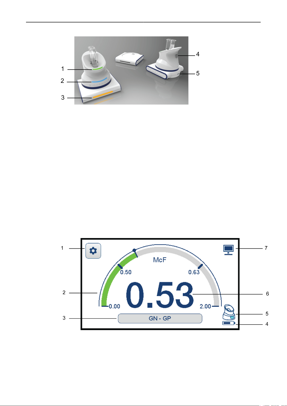
Figure 19: VITEK® DensiCHEK® Display Base
1. Configuration button
2. McFarland Range Meter
3. Card Type button
4. Pod Battery Life icon
5. Pod Pairing Color icon
048641-01 3-11 VITEK® DensiCHEK
Page 6

Display Base Screen System Description and Basic Operations
6. McFarland Value (Example:0.53 McFarland Readinge)
7. PC Connection icon
This screen is applicable for all suspension types (ex. GN, GP, ANC, etc.)
The display screen offers unique reading ranges for each of the following screen views:
• GN - GP
• BCL - YST
• ANC - CBC - NH
• N/A
Table 11: VITEK® DensiCHEK® Display Base Symbols and Screens
Symbol or Screen Description
Pod Battery Life icon - Pod not charging
Pod Battery Life icon - Pod needs to be
charged
Pod Battery Life icon - Pod is charging
Configuration button - Base and Pod pairing
settings and more
PC Connection icon - Base connected to
and communicating with the PC
Home button - McFarland screen access
Left (decrease) Arrow button
Right (increase) Arrow button
Pod Pairing Color button
Display Brightness button
Base Sleep Time button (to enter Power
Save mode)
Tube Light Intensity button
Pod Pairing Color buttons - Pod pairing
color options
048641-01 3-12 VITEK® DensiCHEK
Page 7

Display Base Screen System Description and Basic Operations
Symbol or Screen Description
Configuration screen
Welcome screen
McFarland screen
Update screen - Pod firmware update is
occurring
McFarland Reference screen - A McFarland
Reference is inserted in the Pod (LOT
number value appears)
McFarland screen - Card type is locked by
FLEXprep
™
048641-01 3-13 VITEK® DensiCHEK
Page 8

FLEXprep Software Interface Screen
Symbol or Screen Description
System Description and Basic Operations
McFarland screen - No tube is inserted
McFarland screen - Pod is zeroed
McFarland screen - McFarland value is
captured
FLEXprep Software Interface Screen
The software interface of the VITEK® 2 software is compatible with the VITEK® DensiCHEK
and mimics the look of the Display Base screen.
The software offers the following features when the VITEK® DensiCHEK® Display Base or
Connectivity base is connected to a FLEXprep™ PC:
• FLEXprep™ software mimics the VITEK® DensiCHEK® Display Base, including
configuration settings. (Display Base configuration is only performed on the device.)
• The DensiCHEK Gauge window appears on the PC when the instrument is actively being
used (i.e., a tube is inserted ).
• Pressing the button on the VITEK® DensiCHEK® sends the McFarland value to the PC.
FLEXprep™ only saves the value if it is configured to use a VITEK® DensiCHEK®.
• The following information appears on the connected PC:
IMPORTANT: After pressing the button on
the Pod, the following happens: The
saved McFarland value appears above the
main number on the screen.
®
◦ McFarland Value
◦ DensiCHEK Gauge window with McFarland Range
◦ LOT Number (with the McFarland Reference inserted in the Pod)
• The PC Connection icon appears on the Display Base screen of the VITEK® DensiCHEK
when the instrument is communicating with the connected PC.
• The PC displays the McFarland meter range based on card type. The card type is locked
on the base when a card type selection is made within FLEXprep. The card type and
meter range unlock if the connection is lost, or if the isolate is validated or cancelled in
FLEXprep™.
048641-01 3-14 VITEK® DensiCHEK
®
Page 9

FLEXprep Software Interface Screen
Figure 20: FLEXprep™ with VITEK® DensiCHEK® - Locked Card Type on Display Base
Figure 21: Configuration Screen
System Description and Basic Operations
1. Application Configuration section
2. VITEK® 2 Configuration section
3. McFarland Reference Standard button
Figure 22: Quick McFarland Entry Screen
048641-01 3-15 VITEK® DensiCHEK
Page 10

FLEXprep Software Interface Screen
1. Quick McFarland Entry button
2. McFarland field
3. Isolate field
4. Lab ID field
5. Row Number
Figure 23: Cassette Identification Screen
System Description and Basic Operations
1. Lab ID and Isolate fields
2. VITEK® 2 PC field
3. Cassette ID field
4. User Account
5. Full Screen button
6. Cancel button
7. Validate button
8. Quick McFarland Entry button
9. Layout button
048641-01 3-16 VITEK® DensiCHEK
Page 11

FLEXprep Software Interface Screen
Figure 24: Cassette Definition Screen
System Description and Basic Operations
1. Lab ID and Isolate fields
2. Abbreviated Summary view
3. User Account
4. Full Screen button
5. Full Summary button
6. Send Cassette button
7. Cancel button
8. Validate button
9. McFarland Entries button
10. Card Navigation buttons
11. Delete Card button
12. Add Card button
13. New Cassette button
14. Card Fields
15. QC (Quality Control) button (disabled)
16. Layout button
048641-01 3-17 VITEK® DensiCHEK
Page 12

FLEXprep Software Interface Screen
Figure 25: Quality Control Screen
1. Lab ID and Isolate fields
2. Abbreviated Summary view
3. Labsuper (User Account)
4. Full Screen button
5. Full Summary button
6. Send Cassette button
7. Cancel button
8. Validate button
9. McFarland Entries button
10. Card Navigation buttons
11. Delete Card button
12. Add Card button
13. New Cassette button
14. Card Fields
15. QC (Quality Control) button (enabled)
16. Layout button
System Description and Basic Operations
Figure 26: Cassette Definition Screen with Test Cards
048641-01 3-18 VITEK® DensiCHEK
Page 13

Figure 27: Configuration Screen - Connectivity Base Configuration Section
Performance Ranges
Suspensions for specific cards (ex. GN - GP) must fall within the correct performance ranges.
There are unique screen views with specific ranges for different types of cards. The
McFarland reading ranges are as follows:
Table 12: Display Screens and Corresponding Ranges
Display Screen Displayed Reading Ranges Performance Ranges
GN - GP 0.00 - 2.00 0.50 - 0.63
YST- BCL 0.00 - 4.00 1.80 - 2.20
CBC - NH - ANC 0.00 - 4.00 2.70 - 3.30
System Description and Basic Operations
Related Links
GN and GP
N/A 0.00 - 4.00 N/A
The McFarland meter on the screen appears green, yellow, or red to relay whether the values
are in or out of range:
• If no organism suspension is inserted, the meter appears gray.
• If the organism suspension has a McFarland value that is above the defined performance
range for the selected card type, the meter appears red.
• If the organism suspension has a McFarland value that is below the defined performance
range for the selected card type, the meter appears yellow.
• If the organism suspension has a McFarland value that is within the defined performance
range for the selected card type, the meter appears green.
Preparing Suspensions for ID and AST Cards (Connectivity)
Preparing Suspensions for ID and AST Cards (Standalone)
The GN - GP screen shows a McFarland range of 0.00 to 2.00. The GN and GP suspensions
must fall within the 0.50 and 0.63 range to show an appropriate McFarland reading.
Figure 28: VITEK® DensiCHEK® Display Base Screen - GN and GP
048641-01 3-19 VITEK® DensiCHEK
Page 14

YST and BCL
YST and BCL
The YST - BCL screen shows a McFarland range of 0.00 to 4.00. The YST and BCL
suspensions must fall within the 1.80 and 2.20 range to show an appropriate McFarland
reading.
Figure 29: VITEK® DensiCHEK® Display Base Screen - YST and BCL
CBC, NH, and ANC
The CBC - NH - ANC screen shows a McFarland range of 0.00 to 4.00. The CBC, NH, and
ANC suspensions must fall within the 2.70 and 3.30 range to show an appropriate McFarland
reading.
System Description and Basic Operations
N/A
Figure 30: VITEK® DensiCHEK® Display Base Screen - CBC, NH, and ANC
The N/A screen shows a McFarland range of 0.00 to 4.00.
When you have selected the N/A screen, the system does not alert you when a suspension is
in or out of range. N/A provides the McFarland value for suspensions, but it does not provide
an acceptable range.
Figure 31: VITEK® DensiCHEK® Display Base Screen - N/A
048641-01 3-20 VITEK® DensiCHEK
Page 15

4
System Installation and Configuration
Unpacking the Instrument
1. Inspect the shipping container for external damage.
2. Open the shipping carton, and then remove the instrument from the shipping carton.
3. Carefully remove the instrument from the plastic bag.
4. Remove the remaining parts and documentation from the carton:
• Product Certificates
• VITEK® DensiCHEK® Instrument User Manual CD
5. Place the VITEK® DensiCHEK® instrument on a flat, horizontal surface that is dust free
and away from direct sunlight.
WARNING
Failing to follow the proper installation procedures will result in
incorrect device performance..
Connecting the Device
One of two methods may be used to power the Display base. One method is to connect the
Display Base directly to AC power by use of a Single USB 2.0 to micro-USB and the provided
AC Power Adapter. The second is to connect the Display Base to the PC by use of the 2.0
Dual USB connector to micro-USB. Only one method may be used to power the Connectivity
Base. That is by connecting the Connectivity Base to the PC by use of the Single USB 2.0 to
micro-USB .
If the battery life of the Display Base's Pod is completely depleted, it should be recharged at
the Display Base. When doing so, ensure that either power is applied with the provided AC
Power Adapter, or ensure both ends of the Dual USB connector are plugged into a PC.
048641-01
4-1 VITEK® DensiCHEK
 Loading...