


mini APT
Table of contents
 Loading...
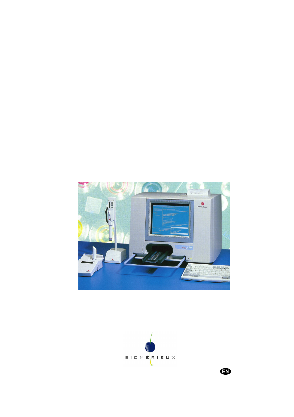
mini API®
Service Manual
Product No. 99 819
Version C
01/2007
bioMérieux sa 69280 Marcy l'Etoile / France
Tel. 33 (0)4 78 87 20 00 - Fax 33 (0)4 78 87 20 90
http://www.biomerieux.com
Printed in France / 673 620 399 RCS Lyon
© 2006 – 2007 bioMérieux SA


501-1584 A en
Argentina
bioMérieux Argentina
Av. Congreso 1745
(C1428BUE) Capital Federal
Buenos Aires
tel. (54) 11 5555-6800
fax (54) 11 5555-6888
Australia
bioMérieux Australia P/L
Unit 25, Parkview Business Center
1 Maitland Place
Baulkham Hills NSW 2153
tel. (61) 2 8852 4700
fax (61) 2 8852 4777
Austria
bioMérieux Austria GmbH
Eduard-Kittenberger-Gasse 97
Top 3
A-1230 Wien
tel. (43) 186 50 650
fax (43) 186 50 661
Belgium
bioMérieux Benelux s.a./n.v.
Media Square
18-19 Place des Carabiniers
Bruxelles 1030
tel. (32) 2 743 01 70
fax (32) 2 733 55 97
Brazil
bioMérieux Brasil SA
Estrada Do Mapua
491 Taquara - Jacarepaguá
CEP 22710 261 Rio de Janeiro R.J
Rio de Janeiro R.J
tel. (55) 21 2444 1400
fax (55) 21 2445 6025
Canada
bioMérieux Canada, Inc.
7815, Henri-Bourassa West
Saint Laurent, QC
H4S 1P7
tel. (1) 514 336 7321
fax (1) 514 807 0015
Chile
bioMérieux Chile S.A.
Seminario 131
Providencia
Santiago
tel. (56) 2634 20 92
fax (56) 2634 20 93
China
bioMérieux China Limited
Room 1601-02B & 10
Est Ocean Centre
n° 24A Jiang Guo Men Nei Street,
100004 Beijing
tel. (86) 10 6515 6963
fax (86) 10 6515 6993
bioMérieux China Limited
Room 2605, South Tower,
World Trade Center
371-375 Huan Shi Dong East Road
510095 Guangzhou
tel. (86) 20 8762 7010
fax (86) 20 8762 7015
Colombia
bioMérieux Colombia Ltda
Avenida 15 No. 100-43
Piso 2
Bogotá D.C.
tel. (57) 1 520 0080
fax (57) 1 520 0088 / 1 520 0831
Czech republic
bioMérieux CZ s.r.o.
Business Park Kosice,
Jinonická 80
158 00 Praha 5
2 57 290 623 / (420) 2 57 290
tel. (420)
232
fax (420) 2 57 290 964
Denmark
bioMérieux Danmark Aps
Smedeholm 13C,
2730 Herlev
tel. (45) 70 10 84 00
fax (45) 70 10 84 01
Finland
bioMérieux Suomi Oy
Konalantie 47 C
FI-00390 Helsinki
tel. (358) 9 8545 6000
fax (358) 9 8545 6045
France
bioMérieux S.A.
69280 Marcy l’Etoile
tel. 33 (0)4 78 87 20 00
fax 33 (0)4 78 87 20 90
http://www.biomerieux.com
Germany
bioMérieux Deutschland GmbH
Weberstrasse 8
D-72622 Nürtingen
tel. (49) 7022 30070
fax (49) 7022 36110
Greece
bioMérieux Hellas S.A.
Papanikoli 70
15232 Halandri
Athens
tel. (30) 210 81 72 400
fax (30) 210 68 00 880
Hungary
bioMérieux Hungária Kft.
Fóti út. 56 (5
H-1047 Budapest
tel. (36) 1 231 3050
fax (36) 1 231 3059
India
bioMérieux India Pvt. Ltd
A-32, Mohan Co-Operative Ind. Estate
New Delhi 110 024
tel. (91) 11 42 09 88 00
fax (91) 11 24 64 88 30
Indonesia
Representation office
bioMérieux Indonesia
Enseval Building
Kawasan Industri Pulo Gadung - JI. Pulo
Lentut No. 10
Jakarta Timur 13920
tel. (62) 21 461 51 11
fax (62) 21 460 41 07
Italy
bioMérieux Italia S.p. A
Via Fiume Bianco, 56
00144 Roma
tel. (39) 0 6 523081
fax (39) 0 6 52308240
Ivory Coast
bioMérieux Afrique Occidentale
08 BP 2634
Abidjan 08
tel. (225) 22 40 93 93 / (225) 22 40 41 40
fax (225) 22 40 93 94
Japan
bioMérieux Japan, Ltd
Seizan Bldg.,
12-28 Kita-Ayoama 2-chome
Minato-ku,
Tokyo 107-0061
tel. (81) 3 5411 87 11
fax (81) 3 5411 87 10
Korea
bioMérieux Korea Co., Ltd
st
& 2nd Floor, Yoosung Building
1
# 830-67 Yoksam-dong, Kangnam ku
Seoul 135-080
tel. (82) 2 2188 4700
fax (82) 2 547 6263
th
Floor)

Mexico
bioMérieux México SA de CV
Chihuahua 88, col. Progreso
México 01080, D.F.
tel. (52) 55 5481 9550
fax (52) 55 5616 2245
Netherlands (The)
bioMérieux Benelux BV
Boseind 15
P.O. Box 23
5280 AA Boxtel
tel. (31) 411 65 48 88
fax (31) 411 65 48 73
New Zealand
bioMérieux New Zealand Ltd
22/10 Airbourne Road
North Harbour
Auckland
tel. (64) 9 415 0601
fax (64) 9 415 0603
Norway
bioMérieux Norge AS
∅kernveien 145
N - 0513 Oslo
tel. (47) 23 37 55 50
fax (47) 23 37 55 51
Philippines (The)
Representation office
bioMérieux Philippines Rep. Office
11th Floor, Pearlbank Centre
146 Valero Street, Salcedo Village
1227 Makati City
tel. (632) 817 7741
fax (632) 812 0896
Poland
bioMérieux Polska Sp. Z.o.o.
ul. Zeromskiego 17
01-882 Warsaw
tel. (48) 22 569 85 00
fax (48) 22 569 85 54
Portugal
bioMérieux Portugal, Lda.
Rua Alto do Montijo,
Lotes 1 e 2 - Portela de Carnaxide
2794-070 Carnaxide
tel. (351) 21 424 59 80
fax (351) 21 418 32 67
Russia
o.o.o. bioMérieux
Petrovsko-Razoumovskii proyezd, 29
127287 Moscow
tel. (7) 495 777 27 09
fax (7) 495 777 27 08 / (7) 495 214 95 41
Spain
bioMérieux España S.A.
Manual Tovar, 45-47
28034 Madrid
tel. (34) 91 358 11 42
fax (34) 91 358 06 29
Sweden
bioMérieux Sverige AB
Hantverksvägen 15
436 33 Askim
tel. (46) 31 68 84 90
fax (46) 31 68 48 48
Switzerland
bioMérieux Suisse s.a.
51, avenue Blanc
Case postale 2150
1211 Genève 2
tel. (41) 22 906 57 60
fax (41) 22 906 57 42
Taiwan
Representation office
bioMérieux China Limited - Taiwan
Branch
RM 608, No. 6-3 Ching Cheng Street
Taipei 105
tel. (886) 2 2545 2250
fax (886) 2 2545 0959
Thaïland
bioMérieux Thaïland Ltd
Regent House Bldg, 16 th Floor
183 Rajdamri Road, Lumpini,
Pathumwan
Bangkok 10330
tel. (66) 2 651 98 00
fax (66) 2 651 98 01
Turkey
bioMérieux Diagnostik A.S.
Değirmen Sok. Nida Plaza Kat:6
34742 Kozyataği / Istanbul
tel. (90) 216 444 00 83
fax (90) 216 373 16 63
United Kingdom
bioMérieux UK Ltd
Grafton Way, Basingstoke
Hampshire RG22 6HY
tel. (44) 1256 461881
fax (44) 1256 816863
USA
bioMérieux, Inc.
100 Rodolphe Street
Durham NC 27712
tel. (1) 919 620 20 00
fax (1) 919 620 22 11
Vietnam
Representation office
bioMérieux Vietnam Rep. Office
Room 4A, 4th Floor
Green House Building
62A Pham Ngoc Thach Street, Ward 6
District 3
Ho Chi Minh City
tel. (84) 88 209 906
fax (84) 88 209 905
Distribution in over 130 countries

V.B 02/2005
Information supplied in this manual may be subject to modifications before
the products described become available.
This manual may contain information or references relating to certain
bioMérieux
®
SA products, software or services which are not available in the
country of release; this shall not mean that bioMérieux
such products, software or services in such country
To request copies of publications or for any technical request, contact
bioMérieux
®
SA or your local distributor.
Liability disclaimer
This manual is provided “AS IS” without any warranty, whether express or
implied, of merchantability, safety, quality, accuracy, performance of products
described on this manual, including an implied warranty of merchantability or
fitness for a particular purpose, non infringement of third parties intellectual
property rights and against an incidental or direct damage.
In no event shall bioMérieux
consequence related to, arising out of or in connection with, any use of this
manual and/or its results by the User and/or any third party.
®
SA intends to market
®
SA be liable for any direct or indirect damage or
In no event shall this manual be construed as an undertaking of
bioMérieux
®
SA, who reserves the right to modify this manual without notice
and shall incur no liability as a result of such modification.
This manual is provided for information purposes only and except for the
present provisions does not constitute a binding document legally.
Intellectual Property
bioMérieux® SA is the sole owner of copyright, patrimonial rights and any
other intellectual property rights in and to this manual and its content subject
to possible third parties rights.
This manual and its content are protected under the provisions of section
L.111-1 and following articles of the French Intellectual Property Code and
International Copyright and Author Rights Treaties.
The rights to use this manual granted herein are non-exclusive and limited to
the extent necessary to use the Software and Instrument. In no event shall
the Users be granted herein any other right to use this manual including
without limitation, the right to reproduce, represent, adapt or translate all or
part of this manual by any mean whatsoever and in any country without the
prior written consent of bioMérieux
®
SA.
Any use of this manual other than expressly permitted hereunder shall be
prosecuted.
IMPORTANT! USE OF THIS MANUAL CONSTITUTES ACCEPTANCE OF THE
CLAUSES ABOVE MENTIONED.

bioMérieux and the blue logo are used, pending and/or registered trademarks belonging
to bioMérieux
®
SA or one of its subsidiaries.
This manual refers to the following third parties’ trademarks:
IBM is an International Business Machines Corporation trademark in some countries.

TABLE OF CONTENTS
LIST OF FIGURES.........................................................................................................V-1
1 HOW TO USE THIS MANUAL................................................................................. 1-1
1.1 Introduction..................................................................................................................................... 1-1
1.2 Scope of the manual ...................................................................................................................... 1-2
1.3 Finding topics and procedures ....................................................................................................... 1-3
1.4 How the manual is organised......................................................................................................... 1-4
2 FUNCTIONAL DESCRIPTION................................................................................. 2-1
2.1 Introduction..................................................................................................................................... 2-1
2.2 Presentation ................................................................................................................................... 2-2
2.3 Introduction to identification and susceptibility testing ................................................................... 2-3
2.4 Description/Aim .............................................................................................................................. 2-4
2.5 General description ........................................................................................................................ 2-5
2.5.1 Configuration components ...................................................................................................... 2-5
2.6 Principle of operation ..................................................................................................................... 2-7
2.6.1 Functions ................................................................................................................................ 2-7
2.6.2 Presentation............................................................................................................................ 2-7
2.6.3 Characteristics ........................................................................................................................ 2-7
2.7 General characteristics .................................................................................................................. 2-9
2.7.1 Environmental conditions........................................................................................................2-9
2.7.2 Physical features..................................................................................................................... 2-9
2.7.3 Electrical characteristics ....................................................................................................... 2-10
2.7.4 Characteristics of optical components .................................................................................. 2-10
2.8 Computer...................................................................................................................................... 2-11
2.9 Central processing unit ................................................................................................................ 2-11
2.10 Software ....................................................................................................................................... 2-11
2.11 Consumables ............................................................................................................................... 2-12
3 PRELIMINARY INSTRUCTIONS ............................................................................. 3-1
3.1 Recommendations for installation and use .................................................................................... 3-2
3.2 Unpacking the mini API................................................................................................................. 3-2
3.3 Assembly and installation............................................................................................................... 3-3
3.3.1 Choosing a location ................................................................................................................ 3-3
3.3.2 Setting up the strip tray ........................................................................................................... 3-5
3.3.3 Connections ............................................................................................................................ 3-5
3.3.4 Preparing for operation ........................................................................................................... 3-5
3.3.5 Adjusting the height of the mini API ......................................................................................... 3-5
mini API Service Manual IV-1

4 DESCRIPTION OF MODULES.................................................................................4-1
4.1 Introduction..................................................................................................................................... 4-1
OVERVIEW.....................................................................................................................4-3
4.2 Precautions..................................................................................................................................... 4-5
4.3 Tools 4-5
4.4 Disassembly and assembly ............................................................................................................ 4-6
mini API..........................................................................................................................4-7
4.5 Cable connections .......................................................................................................................... 4-8
4.6 Principle of operation.................................................................................................................... 4-10
4.6.1 Colorimetric reading .............................................................................................................. 4-10
4.6.2 Nephelometric reading .......................................................................................................... 4-11
4.7 Block diagram of analogue digital converter................................................................................. 4-12
4.7.1 Removing the casing (Casing ASSY) = 452 1040A .............................................................. 4-14
POWER SUPPLY BLOCK ...........................................................................................4-15
4.8 Cable connections ........................................................................................................................ 4-16
4.9 Equipment .................................................................................................................................... 4-17
4.10 Removing the power supply block (451 1324A) .......................................................................... 4-17
4.11 Board power (450 0628A) ............................................................................................................ 4-18
4.11.1 Location................................................................................................................................. 4-18
4.11.2 Removing the board power ................................................................................................... 4-18
4.12 Principle of operation (power supply block).................................................................................. 4-20
4.12.1 Power supply circuit operation .............................................................................................. 4-20
4.12.2 Reader power supply ............................................................................................................ 4-20
4.12.3 Computer power supply ........................................................................................................ 4-20
4.13 Principle of operation (board power) ............................................................................................4-21
4.13.1 Filter motor drive circuit ......................................................................................................... 4-21
4.13.2 Tray motor drive circuit.......................................................................................................... 4-22
4.14 Testing and adjustment ................................................................................................................ 4-23
4.14.1 Reader power supply ............................................................................................................ 4-23
4.14.2 Board power .......................................................................................................................... 4-24
4.14.3 Procedure.............................................................................................................................. 4-25
OPTICAL BLOCK.........................................................................................................4-27
4.15 Optical block cable connections ................................................................................................... 4-28
4.16 Equipment .................................................................................................................................... 4-29
4.17 Removing the optical block........................................................................................................... 4-29
4.18 Condenser (P/N 452 0409A) ........................................................................................................ 4-30
4.18.1 Removing the condenser ...................................................................................................... 4-30
4.19 Lamp (P/N 451 0293A)................................................................................................................. 4-31
4.19.1 Removing the Lamp .............................................................................................................. 4-31
4.19.2 Removing the lamp (cont'd) .................................................................................................. 4-32
4.20 Board optic acquisition (P/N 450 0631A)...................................................................................... 4-33
4.20.1 Location................................................................................................................................. 4-33
4.20.2 Removing the board optic acquisition ................................................................................... 4-33
4.21 Board detection tray (Sync Assy) (P/N 450 0630A) ..................................................................... 4-34
4.21.1 Location................................................................................................................................. 4-34
4.21.2 Removing the board detection tray ....................................................................................... 4-34
IV-2 mini API Service Manual

4.22 Board detection filter holder (P/N 450 0629A) ............................................................................. 4-35
4.22.1 Location ................................................................................................................................ 4-35
4.22.2 Removing the board..............................................................................................................4-35
4.23 Principle of operation ................................................................................................................... 4-36
4.23.1 Lamp states .......................................................................................................................... 4-36
4.23.2 Board optic acquisition.......................................................................................................... 4-37
4.23.3 Board detection tray.............................................................................................................. 4-38
4.23.4 Board detection filter holder .................................................................................................. 4-38
4.24 Testing and alignment.................................................................................................................. 4-39
4.24.1 Lamp and condenser ............................................................................................................ 4-39
4.24.2 Board optic acquisition.......................................................................................................... 4-43
4.24.3 Board detection tray.............................................................................................................. 4-44
MANAGEMENT BLOCK.............................................................................................. 4-47
4.25 Cable connections........................................................................................................................ 4-48
4.26 Equipment .................................................................................................................................... 4-49
4.27 Removing the board COM GEST2............................................................................................... 4-49
4.28 Principle of operation ................................................................................................................... 4-50
4.28.1 RS 232 serial communication ............................................................................................... 4-52
4.28.2 EPROM version communication ........................................................................................... 4-52
4.28.3 Checking the position of the protection rail ........................................................................... 4-52
4.28.4 Initialisation of the reader module ......................................................................................... 4-52
4.28.5 Reading mode....................................................................................................................... 4-52
4.28.6 Reading................................................................................................................................. 4-53
4.28.7 Alarm messages ................................................................................................................... 4-55
4.28.8 Management card .................................................................................................................4-57
BOARD INTERFACE SERIAL LCD CPU .................................................................... 4-59
4.29 Removing the board interface (450 0625A) ................................................................................. 4-61
4.30 Cable connections........................................................................................................................ 4-62
4.31 Principle of operation ................................................................................................................... 4-63
COMPUTER BLOCK WITH BOARD PCM4862 .......................................................... 4-65
4.32 Cable connections........................................................................................................................ 4-67
4.33 Central processing unit ................................................................................................................ 4-68
4.34 Board CPU PCM 4862 (450 0572A) ............................................................................................ 4-69
4.35 Introduction................................................................................................................................... 4-70
4.35.1 Safety precautions ................................................................................................................ 4-70
4.35.2 Removing the board CPU PCM 4862 (450 0572A) .............................................................. 4-70
4.36 Specification................................................................................................................................. 4-71
4.36.1 Standard SBC functions........................................................................................................ 4-71
4.37 Jumpers and connectors.............................................................................................................. 4-74
4.38 SIMM memory modules ............................................................................................................... 4-78
4.39 Detailed information on serial ports.............................................................................................. 4-79
4.39.1 RS-232 port connector (CN13) ............................................................................................. 4-79
4.39.2 RS-232/422/485 Serial Port (CN8) ....................................................................................... 4-80
4.40 Jumper settings............................................................................................................................ 4-81
mini API Service Manual IV-3

COMPUTER BLOCK WITH BOARD PCM4860...........................................................4-85
4.41 Cable connections ........................................................................................................................ 4-87
4.42 Central processing unit................................................................................................................. 4-88
4.43 Board CPU PCM 4860 ................................................................................................................. 4-89
4.44 Introduction................................................................................................................................... 4-90
4.44.1 Safety precautions................................................................................................................. 4-90
4.44.2 Removing the board CPU PCM 4860 ................................................................................... 4-90
4.45 Specifications ............................................................................................................................... 4-91
4.45.1 Standard SBC functions........................................................................................................ 4-91
4.46 Jumpers and connectors .............................................................................................................. 4-94
4.47 SIMM memory modules................................................................................................................ 4-97
4.48 Detailed information on serial ports .............................................................................................. 4-98
4.48.1 RS-232 port connector (JP14)............................................................................................... 4-98
4.48.2 RS-232/422/485 Serial Port (JP9)......................................................................................... 4-99
4.49 Jumper settings .......................................................................................................................... 4-100
4.50 Floppy drive ................................................................................................................................ 4-101
4.50.1 Features .............................................................................................................................. 4-101
4.50.2 Removing the floppy drive and hard disk ............................................................................ 4-101
4.51 Hard disk .................................................................................................................................... 4-102
4.51.1 Features .............................................................................................................................. 4-102
4.52 Display........................................................................................................................................ 4-104
4.52.1 Mechanical data .................................................................................................................. 4-104
4.52.2 Removing the display (451 1023A) ..................................................................................... 4-104
4.53 Cable connections ...................................................................................................................... 4-105
4.53.1 Electrical absolute maximum ratings................................................................................... 4-106
4.53.2 Environmental absolute maximum ratings .......................................................................... 4-106
4.53.3 Electrical characteristics of backlight .................................................................................. 4-107
4.53.4 Precautions for use ............................................................................................................. 4-107
4.53.5 Storage................................................................................................................................ 4-107
4.53.6 Safety .................................................................................................................................. 4-107
PRINTER BLOCK.......................................................................................................4-109
4.54 Outline ........................................................................................................................................ 4-111
4.54.1 Removing the printer ........................................................................................................... 4-111
4.55 Part functional description .......................................................................................................... 4-112
4.56 General specifications ................................................................................................................ 4-113
4.57 Connectors and signals .............................................................................................................. 4-115
4.58 Setting of DIP switches............................................................................................................... 4-116
4.59 mini API printer setting .............................................................................................................. 4-117
4.60 Printer interface box (451 1024a) ............................................................................................... 4-117
4.61 Printer cable connections ........................................................................................................... 4-118
IV-4 mini API Service Manual

5 PREVENTIVE MAINTENANCE ............................................................................... 5-1
5.1 Introduction..................................................................................................................................... 5-1
5.2 Testing the mini API ...................................................................................................................... 5-2
5.3 Preventive maintenance................................................................................................................. 5-3
5.3.1 Cleaning the mini API®........................................................................................................... 5-3
5.3.2 Changing the ribbon................................................................................................................ 5-9
5.3.3 Changing the roll of paper..................................................................................................... 5-10
5.4 Changing the fuse ........................................................................................................................ 5-12
5.5 Field engineer preventive maintenance ....................................................................................... 5-13
6 TROUBLESHOOTING GUIDE................................................................................. 6-1
6.1 Introduction..................................................................................................................................... 6-1
6.2 Overview ........................................................................................................................................ 6-2
6.2.1 Determining the problem.........................................................................................................6-2
6.2.2 Solving the problem ................................................................................................................ 6-2
6.3 Error message troubleshooting ...................................................................................................... 6-3
6.3.1 Error messages appearing in the mini API software.............................................................. 6-3
6.3.2 Reference alarm ..................................................................................................................... 6-4
6.4 Repair by unit replacement ............................................................................................................ 6-6
6.4.1 Flow chart (1) abnormal operation at power on ...................................................................... 6-7
6.4.2 Flow chart (2) abnormal strip tray operation ........................................................................... 6-8
6.4.3 Flow chart (3) incorrect data sent to the computer ................................................................. 6-9
7 MODULE SPARE PARTS........................................................................................ 7-1
7.1 Introduction..................................................................................................................................... 7-1
7.2 List of tools ..................................................................................................................................... 7-2
7.3 Electronic board ............................................................................................................................. 7-2
7.4 Electrical parts................................................................................................................................ 7-3
7.5 Mechanical parts ............................................................................................................................ 7-4
7.6 Cables ............................................................................................................................................ 7-4
8 DIAGRAMS .............................................................................................................. 8-1
8.1 Introduction..................................................................................................................................... 8-1
9 APPENDIX - MAINTENANCE SOFTWARE .......................................................... 9-13
9.1 Introduction................................................................................................................................... 9-13
9.2 Getting started.............................................................................................................................. 9-14
9.3 Overview ...................................................................................................................................... 9-15
9.3.1 Function "[F4] Filter Values" ................................................................................................. 9-15
9.3.2 Function "[F1] Config" ........................................................................................................... 9-15
9.3.3 Function "[F2] Adjustment" ................................................................................................... 9-16
9.3.4 Function "[F3] Reading" ........................................................................................................ 9-27
10 GLOSSARY ........................................................................................................ 10-1
11 INDEX.................................................................................................................. 11-1
mini API Service Manual IV-5


LIST OF FIGURES
Page
2. FUNCTIONAL DESCRIPTION
Figure 2–1: Using mini API®............................................................................................2-3
Figure 2–2: Description of the spectral zone ....................................................................2-6
Figure 2–3: Optics layout.................................................................................................. 2-6
Figure 2–4: Filter wheel .................................................................................................... 2-6
Figure 2–5: Configuration components.............................................................................2-8
3. PRELIMINARY INSTRUCTIONS
Figure 3–1: Setting up the strip tray.................................................................................. 3-4
Figure 3–2: Connections...................................................................................................3-4
4. DESCRIPTION OF MODULES
Figure 4–1: Cable connections ......................................................................................... 4-8
Figure 4–2: Calculation of numerical values .....................................................................4-9
Figure 4–3: Transmission graph ..................................................................................... 4-10
Figure 4–4: Filter wheel .................................................................................................. 4-10
Figure 4–5: Analogue-digital converter........................................................................... 4-12
Figure 4–6: Position of casing screws ............................................................................ 4-13
Figure 4–7: Power supply cable connections .................................................................4-16
Figure 4–8: Removing the power supply block ...............................................................4-17
Figure 4–9: Removing the board power .........................................................................4-18
Figure 4–10: Power supply circuit block diagram ...........................................................4-19
Figure 4–11: Filter motor drive circuit ............................................................................. 4-21
Figure 4–12: Tray motor drive circuit .............................................................................. 4-22
Figure 4–13: Switching power supply card testing and adjustment ................................ 4-23
Figure 4–14: Board power .............................................................................................. 4-24
Figure 4–15: Detection of the tray dt = 200ms (tray speed)............................................ 4-25
Figure 4–16: Optical block cable connections ................................................................4-28
Figure 4–17: Removing the optical block........................................................................4-29
Figure 4–18: Removing the condenser........................................................................... 4-30
Figure 4–19: Removing the lamp.................................................................................... 4-31
Figure 4–20: Handling the lamp...................................................................................... 4-32
mini API Service Manual V-1

Figure 4–21: Removing the board optic acquisition ....................................................... 4-33
Figure 4–22: Removing the board detection tray ........................................................... 4-34
Figure 4–23: Removing the board detection filter holder................................................ 4-35
Figure 4–24: Lamp control drive circuit .......................................................................... 4-36
Figure 4–25: Analogical switching.................................................................................. 4-37
Figure 4–26: Board detection tray circuit........................................................................ 4-38
Figure 4–27: Board detection filter holder circuit............................................................ 4-38
Figure 4–28: Beam alignment ........................................................................................ 4-39
Figure 4–29: Strip code reading..................................................................................... 4-41
Figure 4–30: Oscillogram and holes on the tray............................................................. 4-41
Figure 4–31: Position of the beams ............................................................................... 4-43
Figure 4–32: Alignment of the board detection tray ....................................................... 4-45
Figure 4–33: Management block cable connections ...................................................... 4-48
Figure 4–34: Removing the board COM GEST2............................................................ 4-49
Figure 4–35: Management block diagram...................................................................... 4-51
Figure 4–38: Removing the board interface ................................................................... 4-60
Figure 4–39: Board interface serial LCD CUP cable connections.................................. 4-62
Figure 4–40: Computer cable connections..................................................................... 4-67
Figure 4–41: Removing the board CPU ......................................................................... 4-69
Figure 4–42: PCM-4862 jumpers ................................................................................... 4-73
Figure 4–43: PCM-4862 connectors .............................................................................. 4-76
Figure 4–44: PCM-4862 BIOS Settings ......................................................................... 4-83
Figure 4–45: Computer cable connections..................................................................... 4-87
Figure 4–46: Removing the board CPU ......................................................................... 4-89
Figure 4–47: PCM-4860 jumpers ................................................................................... 4-93
Figure 4–48: PCM-4860 connectors .............................................................................. 4-95
Figure 4–49: Display .................................................................................................... 4-103
Figure 4–50: Display cable connections....................................................................... 4-105
Figure 4–51: Printer ..................................................................................................... 4-110
Figure 4–52: Power supply connector.......................................................................... 4-115
Figure 4–53: DIP switch setting ................................................................................... 4-117
Figure 4–54: Printer cable connections........................................................................ 4-118
Figure 4–55: Printer interface circuit ............................................................................ 4-119
V-2 mini API Service Manual

5. PEVENTIVE MAINTENANCE
Figure 5–1: Strip tray ........................................................................................................ 5-4
Figure 5–2: Preparing the photodiode cleaning tool ......................................................... 5-6
Figure 5–3: Cleaning the photodiodes.............................................................................. 5-6
Figure 5–4: Changing the ribbon and the roll of paper .....................................................5-8
Figure 5–5: Printer cover .................................................................................................. 5-8
Figure 5–6: Paper cutter................................................................................................... 5-9
Figure 5–7: Loading the paper........................................................................................ 5-11
Figure 5–8: Back panel of the mini API .........................................................................5-12
6. TROUBLESHOOTING
Figure 6–1: Optical interrupt of the tray ............................................................................ 6-5
TABLES
Table A: Recommended tools ..........................................................................................4-5
Table B: Equipment required for maintenance .................................................................4-6
Table C: Limits................................................................................................................4-42
Table D: Symptom and flow chart references................................................................... 6-6
mini API Service Manual V-3


1 HOW TO USE THIS MANUAL
1.1 INTRODUCTION
This chapter explains how to use the mini API® Service Manual.
It is structured as follows:
SCOPE OF THE MANUAL.......................................................................... 1-2 ♦
♦
FINDING TOPICS AND PROCEDURES..................................................... 1-3
♦
HOW THE MANUAL IS ORGANISED.........................................................1-4
mini API Service Manual 1-1

1.2 SCOPE OF THE MANUAL
The mini API® Service Manual is designed to enable the Field Service Engineers
involved in maintenance tasks to accurately diagnose problems in order to repair
the mini API.
This chapter explains how the manual is organised and how it should be used.
The Table of Contents lists all the chapters the manual deals with. Each chapter is
subdivided into sections corresponding to a procedure or a precise description.
The reply to a question can readily be found by referring to the Table of Contents
or the Index at the back of the manual.
1-2 mini API Service Manual

1.3 FINDING TOPICS AND PROCEDURES
The mini API® Service Manual is divided into 12 chapters to help you find what
you are looking for.
Table of contents
The main table of contents of the manual is located on pages IV-1 to IV-5. It
lists each chapter and the procedures or topics they contain.
List of figures
Pages V-1 to V-3 contain a list of the figures of the manual.
Chapter contents
Each chapter starts with a specific table of contents. Each table of contents
shows the page from which the different sub-chapters start, on the right of
the page.
Page footers
Each page of the manual has a page footer.
The footers contain the title of the manual and the page number.
Index
A standard topical index is located at the back of the manual in chapter 11. It
is used to locate a particular description or procedure.
mini API Service Manual 1-3

1.4 HOW THE MANUAL IS ORGANISED
This manual is designed to provide you with step-by-step procedures for proper
maintenance of your mini API
®
.
Use this Service Manual when you want background or more detailed information
on the mini API components.
This chapter explains how the Service Manual is organised and how it should be
used.
FUNCTIONAL DESCRIPTION
Chapter 2 gives an overview of the mini API.
− Instrument functions
− Instrument operating principle
− Characteristics and specifications
PRELIMINARY INSTRUCTIONS
Chapter 3 describes the installation procedure and the procedure for
preliminary controls.
DESCRIPTION OF THE MODULES
Chapter 4 gives for each module:
− Its function.
− The position on the instrument.
− A block diagram.
− Diagrams and technical drawings.
− Procedures allowing you to assemble/disassemble the module.
− Procedures to maintain and repair the instruments.
PREVENTIVE MAINTENANCE
Chapter 5 describes the customer's schedule for maintenance as well as the
ATI maintenance.
TROUBLESHOOTING GUIDE
Chapter 6 describes all possible failures and gives the decision tree.
1-4 mini API Service Manual

MODULE SPARE PARTS
Chapter 7 gives the list of specific tools required to perform the adjustments
and carry out repairs on the instruments.
It also gives you the list of spare parts.
DIAGRAMS
Chapter 8 gives you the block diagrams for the mini API
®
boards.
MAINTENANCE SOFTWARE
Chapter 9 contains the description of the maintenance software used for the
reader.
GLOSSARY
Chapter 10 contains an alphabetical list of terms used in this manual and
their definitions.
INDEX
A standard topical index is located at the back of the manual in chapter 11.
mini API Service Manual 1-5


2 FUNCTIONAL DESCRIPTION
2.1 INTRODUCTION
The following topics are presented in this chapter:
PRESENTATION......................................................................................... 2-2 ♦
♦
INTRODUCTION TO IDENTIFICATION AND
SUSCEPTIBILITY TESTING ....................................................................... 2-3
♦
DESCRIPTION............................................................................................ 2-4
♦
GENERAL DESCRIPTION.......................................................................... 2-5
- Configuration components
- Hardware
- Software
- Consumables
♦
PRINCIPLE OF OPERATION .....................................................................2-7
- Functions
- Presentation
- Characteristics
♦
GENERAL CHARACTERISTICS................................................................. 2-9
- Environmental conditions
- Physical features
- Electrical characteristics
- Characteristics of optical components
♦
COMPUTER.............................................................................................. 2-11
♦
CENTRAL PROCESSING UNIT................................................................ 2-11
♦
SOFTWARE .............................................................................................. 2-11
♦
CONSUMABLES .......................................................................................2-12
mini API Service Manual 2-1

2.2 PRESENTATION
The mini API® is an automatic system for bacterial identification and susceptibility
testing. It can be divided into four categories of elements:
hardware
software
consumables
user's manual
2-2 mini API Service Manual
A
TM
A
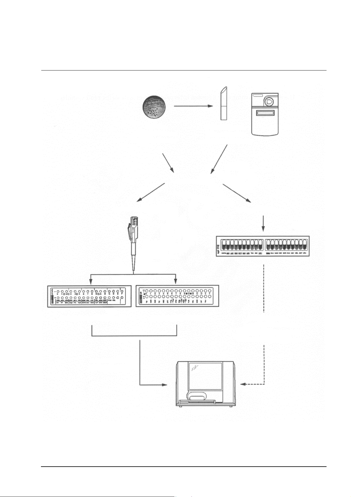
2.3 INTRODUCTION TO IDENTIFICATION AND SUSCEPTIBILITY TESTING
Isolation medium
orientation tests
utomated technique
Standardised
inoculation using
the electronic
pipette
Standardisation
of the inoculum
using the
DENSIMAT
Choice of strips
Manual technique
ID 32 or rapid ID 32 strips ATB
utomatic reading
and interpretation.
or rapid ATB strips
mini API
Visual reading.
Entry of biochemical
profiles via the keyboard.
Automatic interpretation.
Figure 2–1: Using mini API®
mini API Service Manual 2-3

2.4 DESCRIPTION/AIM
The mini API® is designed for the automatic identification and susceptibility testing
of ID 32, rapid ID 32, ATB
It also enables computer assisted interpretation of API
TM
and rapid ATB strips.
®
strips read visually.
2-4 mini API Service Manual

2.5 GENERAL DESCRIPTION
2.5.1 Configuration components
The mini API® is an automated instrument for identification and susceptibility
testing. It consists of:
− hardware,
− software,
− consumables.
2.5.1.1 Hardware
The package includes:
The mini API, a self-contained analytical module enabling:
− reading of test strips,
− management of results and data,
− printing of results obtained.
a DENSIMAT densitometer to standardise the turbidimetry of the bacterial
suspension (please refer to the manual supplied with the densitometer).
an electronic pipette to dispense the required amount of bacterial suspension
into each cupule of the identification and susceptibility test strips (55 µl or
135 µl) (please refer to the manual supplied with the pipette).
2.5.1.2 Software
The mini API software enables:
− interpretation of data,
− interpretation of strip results (identification or susceptibility tests),
− expert analysis of susceptibility tests,
− storage of results on the hard disk,
− printing of results,
− extraction of data,
− connection with a central computer.
2.5.1.3 Consumables
The mini API consumables include:
− strips with associated media and reagents
− ribbons and paper for the printer,
− pipette tips.
(see package inserts),
mini API Service Manual 2-5
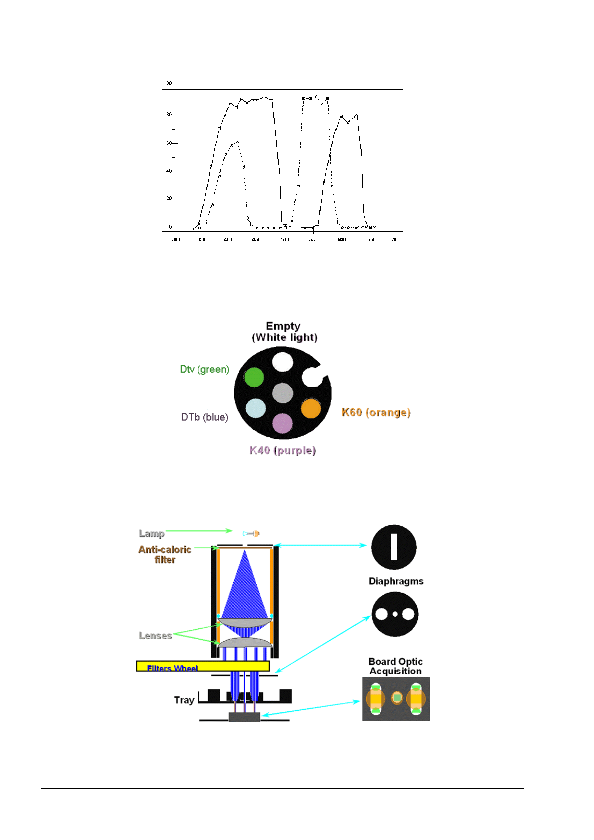
transmission %
Wavelength in mm
Figure 2–2: Description of the spectral zone
Figure 2–3: Optics layout
Figure 2–4: Filter wheel
2-6 mini API Service Manual

2.6 PRINCIPLE OF OPERATION
2.6.1 Functions
− Strip identification by strip decoding
− Two types of readings:
− turbinephelometric
− colorimetric
− Communication with the computer.
2.6.2 Presentation
− Black strip carriage.
− Blue protection rail.
2.6.3 Characteristics
− Description of the spectral zone.
− Reading principle of the test strip reader:
Turbinephelometric reading
Turbinephelometric reading is used for test strips containing assimilation tests:
Example: ID 32 GN, ID 32 C, ATB UR.
A turbinephelometric reading cycle occurs in two stages:
1- Entry of the strip carriage.
Detection of the strip code.
2- Measurement without a filter.
Exit of the strip carriage.
At the end of the cycle, the result is transmitted to the computer.
Colorimetric reading
Colorimetric reading is used for strips containing chromogenic substrates:
Example: ID 32 STAPH, rapid ID 32 A, rapid ID 32 E
A colorimetric reading cycle occurs in 4 stages:
1- 1st entry of the strip carriage:
Detection of the strip code,
Measurement under a K60 filter.
2- 1st exit of the strip carriage:
Measurement under a K40 filter.
3- 2nd entry of the strip carriage:
Measurement under a DTb (blue) filter.
4- 2nd exit of the strip carriage:
Measurement under a DTv (green) filter.
At the end of the reading cycle, the result is transmitted to the computer.
mini API Service Manual 2-7

1- mini API®
2- Keyboard
3- Electronic pipette
4- DENSIMAT Densitometer
Figure 2–5: Configuration components
2-8 mini API Service Manual
Loading...