

Page 1

Instrument User Manual
[04]
510731-10EN1 (06/2008)
24262
bioMérieux, Inc.
Box 15969
Durham, North Carolina 27704-0969 / USA
Tel. (1) 800-682-2666
EC REP
bioMérieux
au capital de 12 029 370 €
673 620 399 RCS LYON
69280 Marcy l’Etoile / France
tél. 33 (0)4 78 87 20 00 / fax 33 (0)4 78 87 20 90
http://www.biomerieux.com
®
SA
Page 2

Argentina
bioMérieux Argentina
Av. Congreso 1745
C1428BUE
Capital Federal Buenos Aires
tel. (54) 11 5555 6800
fax (54) 11 5555 6888
Australia
bioMérieux Australia P/L
Unit 25 - Parkview Business Centre
1, Maitland Place
Baulkham Hills NSW 2153
tel. (61) 2 8852 4700
fax (61) 2 8852 4777
Austria
bioMérieux Austria GmbH
Eduard-Kittenberger-Gasse 97
Top 3
A-1230 Wien
tel. (43) 186 50 650
fax (43) 186 50 661
Belgium
bioMérieux Benelux s.a./n.v.
Media Square
18–19 Place des Carabiniers
Bruxelles 1030
tel. (32) 2 743 01 70
fax (32) 2 733 55 97
Brazil
bioMérieux Brasil SA
Estrada Do Mapuá
491 Taquara - Jacarepaguá
CEP 22710 261
Rio de Janeiro RJ
tel. (55) 21 2444 1400
fax (55) 21 2455 6025
Canada
bioMérieux Canada, Inc.
7815, Henri-Bourassa West
Saint Laurent, QC
H4S 1P7
tel. (1) 514 336 7321
fax (1) 514 807 0015
Chile
bioMérieux Chile S.A.
Seminario 131
Providencia
Santiago
tel. (56) 2634 20 92
fax (56) 2634 20 93
China
bioMérieux China Limited
Room 1601-02B & 10
Est Ocean Centre
nº 24A Jiang Guo Men Nei Street
100004 Beijing
tel. (86) 10 6515 6963
fax (86) 10 6515 6993
bioMérieux China Limited
Room 2605, South Tower,
World Trade Center
371-375 Huan Shi Dong East Road
510095 Guangzhou
tel. (86) 20 8762 7010
fax (86) 20 8762 7015
Colombia
bioMérieux Colombia Ltda
Avenida 15 No. 100-43
Piso 2
Bogotá, D.C.
tel. (57) 1 520 0080
fax (57) 1 520 0088
(57) 1 520 0831
Czech Republic
bioMérieux CZ s.r.o.
Business Park Kosice
Jinonická 80
158 00 Praha 5
tel. (420) 2 57 290 623
(420) 2 57 290 232
fax (420) 2 57 290 964
Denmark
bioMérieux Danmark Aps
Smedeholm 13C
2730 Herlev
tel. (45) 70 10 84 00
fax (45) 70 10 84 01
Finland
bioMérieux Suomi Oy
Konalantie 47 C
FI-00390 Helsinki
tel. (358) 9 8545 6000
fax (358) 9 8545 6045
France
bioMérieux SA
69280 Marcy l’Etoile
tel. (33) 0(4) 78 87 20 00
fax (33) 0(4) 78 87 20 90
http://www.biomerieux.com
Germany
bioMérieux Deutschland GmbH
Weberstrasse 8
D 72622 Nürtingen
tel. (49) 7022 30070
fax (49) 7022 36110
Greece
bioMérieux Hellas S.A.
Papanikoli 70
15232 Halandri
Athens
tel. (30) 210 81 72 400
fax (30) 210 68 00 880
Hungary
bioMérieux Hungária Kft.
Fóto út. 56 (5. emelet)
H-1047 Budapest
tel. (36) 1 231 3050
fax (36) 1 231 3059
India
bioMérieux India Pvt. Ltd
A-32, Mohan Co-Operative Ind. Estate
New Delhi 110 024
tel. (91) 11 42 09 88 00
fax (91) 11 24 64 88 30
Indonesia
Representation Office
bioMérieux Indonesia
Enseval Building
Kawasan Industri Pulo Gadung JI. Pulo - Lentut No. 10
Jakarta Timur 13920
tel. (62) 21 461 51 11
fax (62) 21 460 41 07
Italy
bioMérieux Italia S.p.A.
Via Fiume Bianco, 56
00144 Roma
tel. (39) 06 523 081
fax (39) 06 523 08240
Ivory Coast
bioMérieux Afrique Occidentale
08 BP 2634
Abidjan 08
tel. (225) 22 40 93 93/22 40 41 40
fax (225) 22 40 93 94
Japan
Sysmex bioMérieux, Ltd.
Seizan Bldg.
12-28 Kita-Aoyama 2-chome
Minato-ku, Tokyo 107-0061
tel. (81) 3 5411 87 11
fax (81) 3 5411 87 10
Korea
bioMérieux Korea Co., Ltd.
1st & 2nd Floor, Yoosung Building
# 830-67 Yeoksam-dong,
Kangnam-gu
Séoul 135-080
tel. (82) 2 2188 4700
fax (82) 2 547 6263
Mexico
bioMérieux México SA de CV
Chihuahua 88, col. Progreso
México 01080, D.F.
tel. (52) 55 5481 9550
fax (52) 55 5616 2245
Netherlands (The)
bioMérieux Benelux BV
Boseind 15
P.O. Box 23
5280 AA Boxtel
tel. (31) 411 65 48 88
fax (31) 411 65 48 73
New Zealand
bioMérieux New Zealand Ltd.
C/- Logical Freight Solutions
12C Rennie Drive, Airport Oaks
Auckland
tel. (64) 9 918 6354
fax (64) 9 918 6355
i Manual Name
702358-4EN1 REV nn/nnnn
Page 3

Norway
bioMérieux Norge AS
Økernveien 145
N-0513, Oslo
tel. (47) 23 37 55 50
fax (47) 23 37 55 51
Philippines (The)
Representation Office
bioMérieux Philippines
11th Floor, Pearlbank Centre
146 Valero Street, Salcedo Village
1227 Makati City
tel. (632) 817 7741
fax (632) 812 0896
Poland
bioMérieux Polska Sp. Z.o.o.
Ul. Zeromskiego 17
01-882 Warsaw
tel. (48) 22 569 85 00
fax (48) 22 569 85 54
Portugal
bioMérieux Portugal, Lda.
Av. 25 de Abril de 1974, nº 23-3º
2795-197 LINDA-A-VELHA
tel. (351) 21 415 23 50
fax (351) 21 418 32 67
Russia
o.o.o. bioMérieux
Derbenevskaya ul. 20, str. 11
115 114 Moscow
tel. (7) 495 221 10 79
fax (7) 495 221 10 79
Spain
bioMérieux España S.A.
Manual Tovar, 45–47
28034 Madrid
tel. (34) 91 358 11 42
fax (34) 91 358 06 29
Sweden
bioMérieux Sverige AB
Hantverksvägen 15
436 33 Askim
tel. (46) 31 68 84 90
fax (46) 31 68 48 48
Switzerland
bioMérieux Suisse s.a.
51, avenue Blanc
Case postale 2150
1211 Genève 2
tel. (41) 22 906 57 60
fax (41) 22 906 57 42
Taiwan
Representation Office
bioMérieux China Limited
Taiwan Branch
RM 608, No. 6-3 Ching Cheng Street
Taipei 105
tel. (886) 2 2545 2250
fax (886) 2 2545 0959
Thailand
bioMérieux Thailand Ltd
Regent House Bldg, 16th Floor
183 Rajdamri Road, Lumpini,
Pathumwan
Bangkok 10330
tel. (66) 2 651 98 00
fax (66) 2 651 98 01
Turkey
bioMérieux Diagnostik A.S.
ğirmen Sok. Nida Plaza Kat:6
De
34742 Kozyata
tel. (90) 216 444 00 83
fax (90) 216 373 16 63
United Kingdom
bioMérieux UK Ltd
Grafton Way, Basingstoke
Hampshire RG22 6HY
tel. (44) 1256 461881
fax (44) 1256 816863
USA
bioMérieux, Inc.
100 Rodolphe Street
Durham NC 27712
tel. (1) 919 620 2000
Vietnam
Representation Office
bioMérieux Vietnam
Room 4A, 4th Floor
Green House Building
62A Pham Ngoc Thach Street, Ward 6
District 3
Ho Chi Minh City
tel. (84) 88 209 906
ği-Istanbul
Manual Name ii
702358-4EN1 REV nn/nnnn
Page 4

Liability Disclaimer
bioMérieux, Inc. makes no express or implied warranty
regarding this manual, its quality, performance, or appropriate
use regarding any type of specific procedure.
Furthermore, this manual may be modified by bioMérieux
without notice and without implying any obligation or liability on
the part of the company.
Intellectual Property
bioMérieux, the blue logo, bioLIAISON and VITEK are used,
pending and/or registered trademarks belonging to bioMérieux
SA or one of its subsidiaries.
© 2008 by bioMérieux, Inc. All rights reserved.
No part of this publication may be reproduced, transmitted,
transcribed, stored in a retrieval system, or translated into any
language (human or computer) in any form, or by any means
whatsoever, without the prior express written permission of
bioMérieux, Inc.
Patent Information
Product covered by one or more of U.S. Patent Numbers
D377,455; 5,670,375; 5,674,454; 5,697,409; 5,736,102;
5,762,873; 5,762,874; 5,798,084; 5,798,085; 5,853,666;
5,853,667; 5,856,193; 5,869,006; 5,881,781; 5,888,455;
5,891,396; 5,897,835; 5,925,884; 5,955,736; 5,965,090;
6,024,921; 6,086,824; 6,136,270; 6,156,565; D414,272;
D437,797; 5,609,828; 5,746,980; 5,804,437; 5,869,005;
5,932,177; 5,951,952; 6,267,929; 6,309,890; 6,340,573;
D397,611; D393,592; and Foreign Counterparts.
Page 5

Warranty
Seller, bioMérieux, Inc., warrants the VITEK® 2 instrument (the
“instrument”) to the original purchaser for a period of one (1)
year after date of installation against defects in material and
workmanship and defects arising from failure to conform to
specifications applicable on the date of installation. Seller
further agrees to correct, either by repair, or, at its election, by
replacement, any such defect found on examination to have
occurred, under normal use and service, during such one (1)
year period, provided Seller is promptly notified in writing upon
discovery of such defect.
Seller shall not be liable under this Warranty for any defect
arising from abuse of the system, failure to operate and
maintain the system in accordance with the documentation
included with the Instrument, including repair service, alteration
or modification of the system by any person other than service
personnel of bioMérieux, Inc., or Seller; or use of modified,
changed, or previously used disposables.
The Warranty of Seller set forth above and the obligations
and liabilities of Seller thereunder are exclusive and in lieu
of all other remedies or warranties, express or implied,
arising by law or otherwise, with respect to the system
delivered hereunder (including without limitation any
obligation of Seller with respect to merchantability, fitness
for particular purpose, and consequential damages, and
whether or not occasioned by Seller’s negligence).
This Warranty shall not be extended or altered except by written
instrument signed by Seller.
All of the product elements in the Seller’s Instrument and the
total instrument are warranted to be new or equivalent to new
for the full product warranty period of one year. Disposables
and replacement items with a normal life expectancy of less
than one (1) year, such as batteries and bulbs, are excluded
from this warranty.
Page 6

Page 7
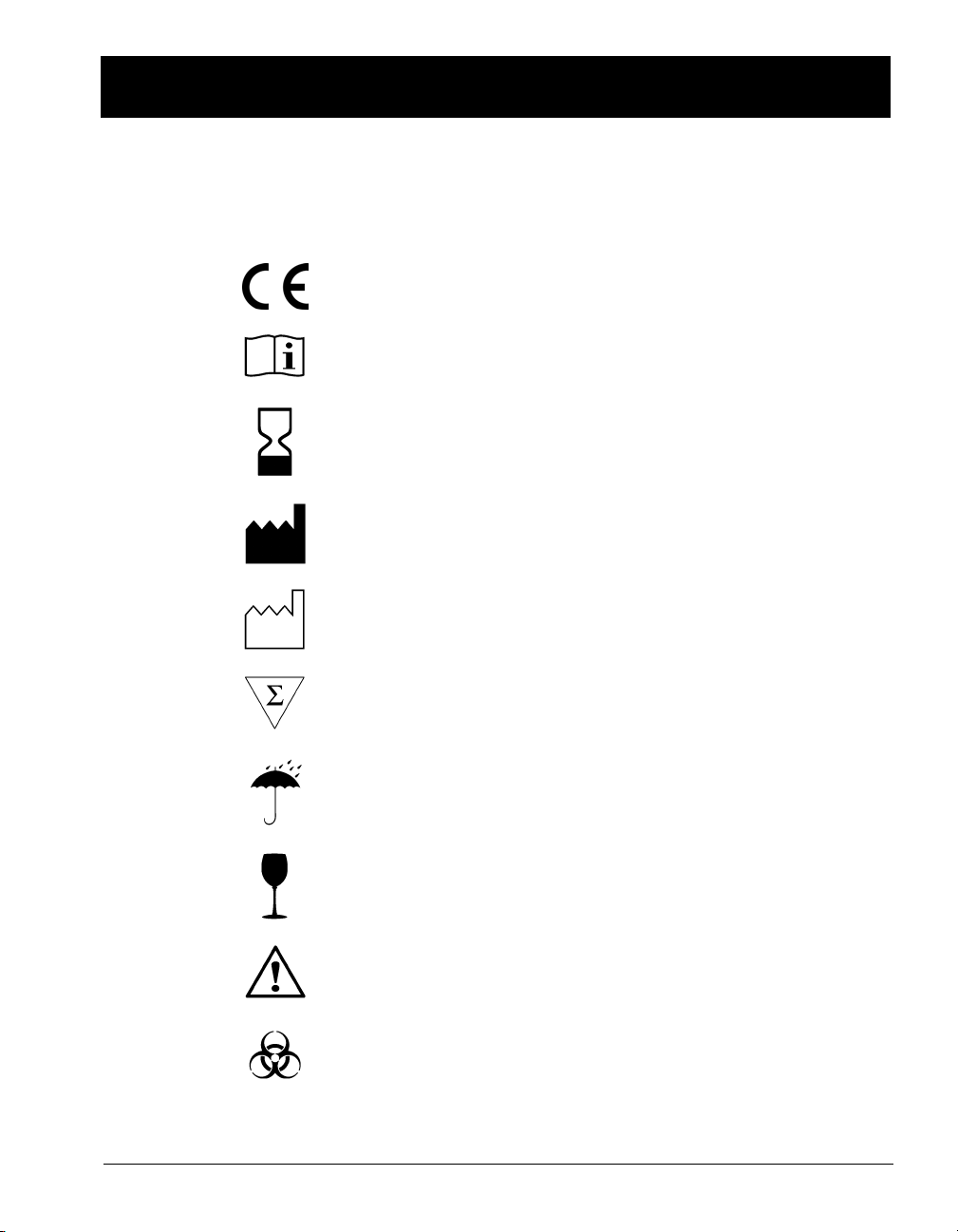
STANDARD SYMBOLS
The following table presents symbols that may appear in the instructions for
use or on the instrument, package inserts, or packaging.
CE-Marking of Conformity
Consult Instructions for Use
Use by
Manufacturer
Date of manufacture
Contains sufficient for <n> tests
Keep dry
Fragile, handle with care
Caution, consult accompanying documents
Biological risks
Manual Name i
702357-3EN1 REV nn/nnnn
Page 8
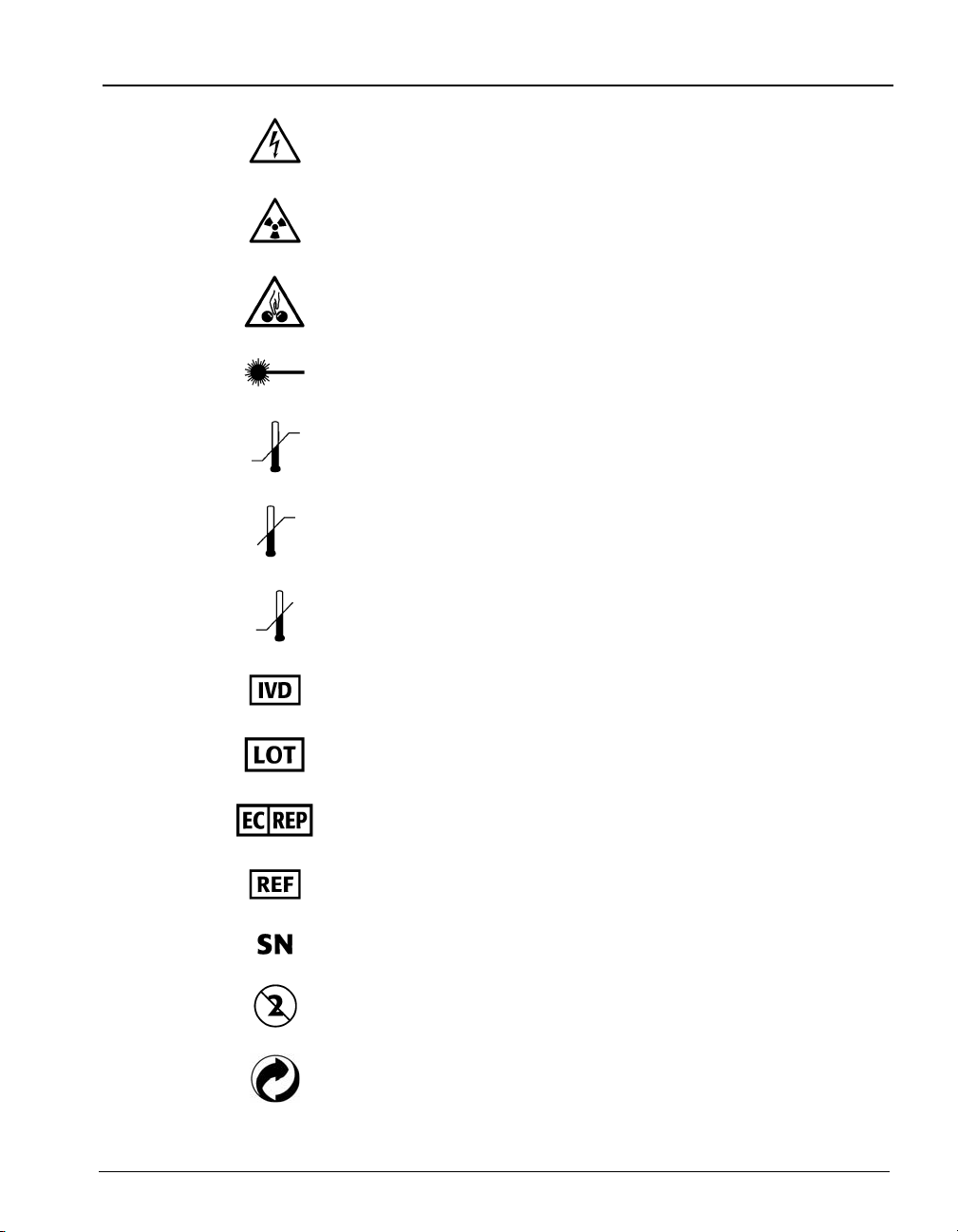
Electric shock warning
Radiation warning
Potential pinch-point warning
Laser
Temperature limitation
Upper limit of temperature
Lower limit of temperature
Standard Symbols
In Vitro Diagnostic Medical Device
Batch code
Authorized Representative in the European Community
Catalog number
Serial Number
Do not reuse
Recyclable
ii Manual Name
702357-3EN1 REV nn/nnnn
Page 9
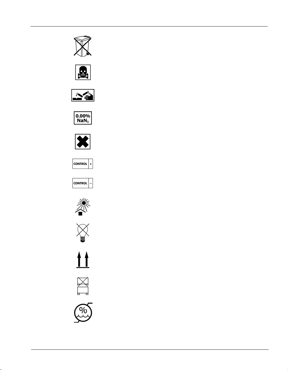
Standard Symbols
Separate collection for waste electrical and electronic
equipment
Very toxic
Corrosive
Sodium azide
Irritant
Positive control
Negative control
Keep away from sunlight
Protect from light
This way up
Do not stack
Humidity limitation
Manual Name iii
702357-3EN1 REV nn/nnnn
Page 10
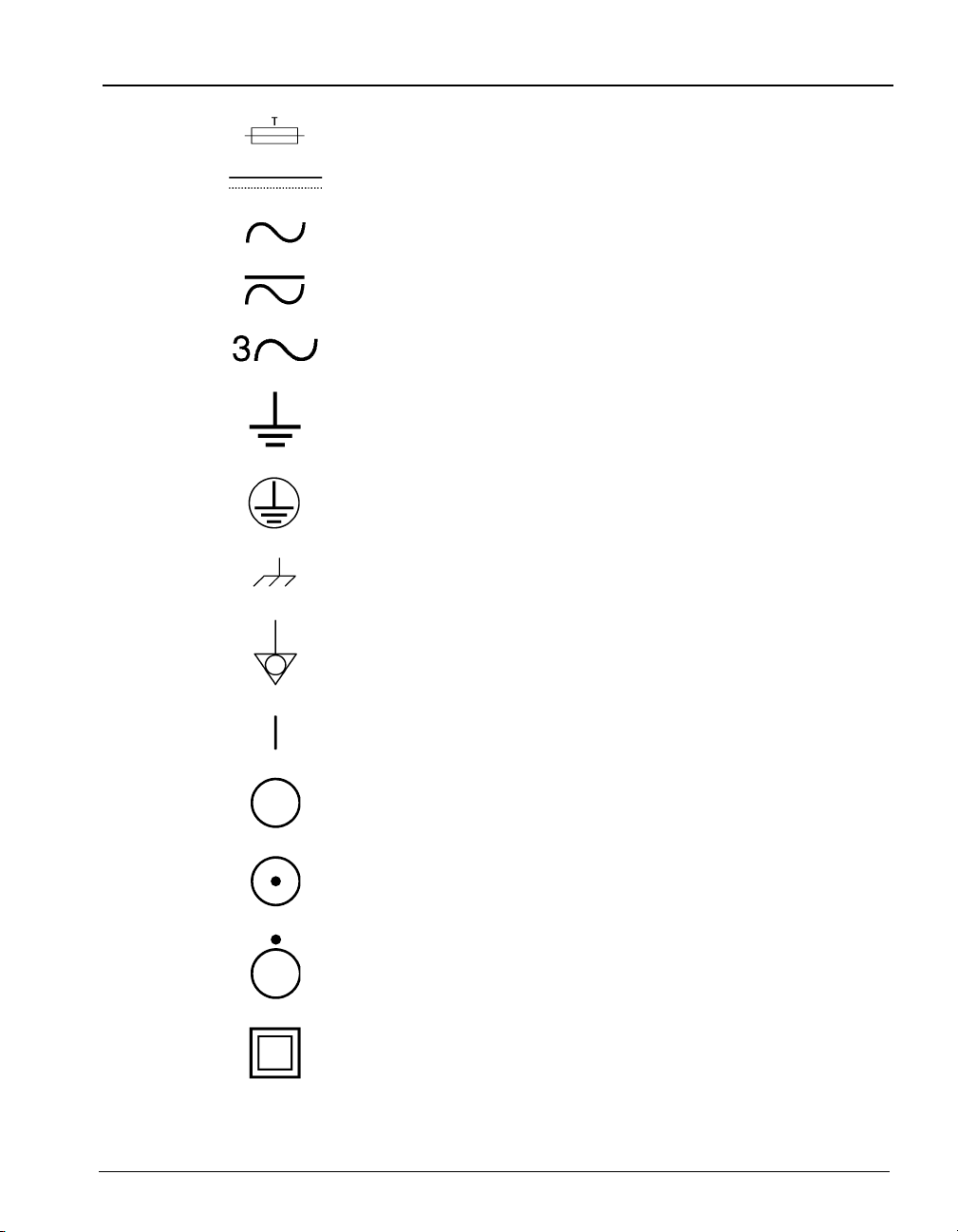
Fuse
Direct current
Alternating current
Both direct and alternating current
Three-phase alternating current
Earth (ground) terminal
Protective conductor terminal
Frame or chassis terminal
Standard Symbols
Equipotentiality
ON (supply)
OFF (supply)
ON (only for a component of the system equipment)
OFF (only for a component of the system equipment)
Equipment protected throughout by double insulation or
reinforced insulation (Equivalent to Class II of IEC 536)
iv Manual Name
702357-3EN1 REV nn/nnnn
Page 11

GENERAL WARNINGS
IMPORTANT: The user is advised to read and understand all instructions in this
manual to be able to derive the best performance from the VITEK® 2
instrument and the Smart Carrier Station.
IMPORTANT: The configuration that you have purchased is adapted to the legislation
and standards of the different countries it will be sent to. For this
reason, it may differ from the one presented in this document. However,
this will have no effect on the performance of your VITEK® 2 instrument
or the Smart Carrier Station. For further information on peripherals
(computer, printer, monitor, etc.) please refer to the relevant
manufacturers’ instruction manuals.
IMPORTANT: If either the VITEK® 2 instrument or the Smart Carrier Station does not
respond properly to keyboard inputs after an inadvertent electrostatic
discharge or electrical fast transient, turn the power off, then back on
using the power switch and resume normal operations.
VITEK® 2 Instrument User Manual i
510731-10EN1
Page 12
General Warnings
General Warnings
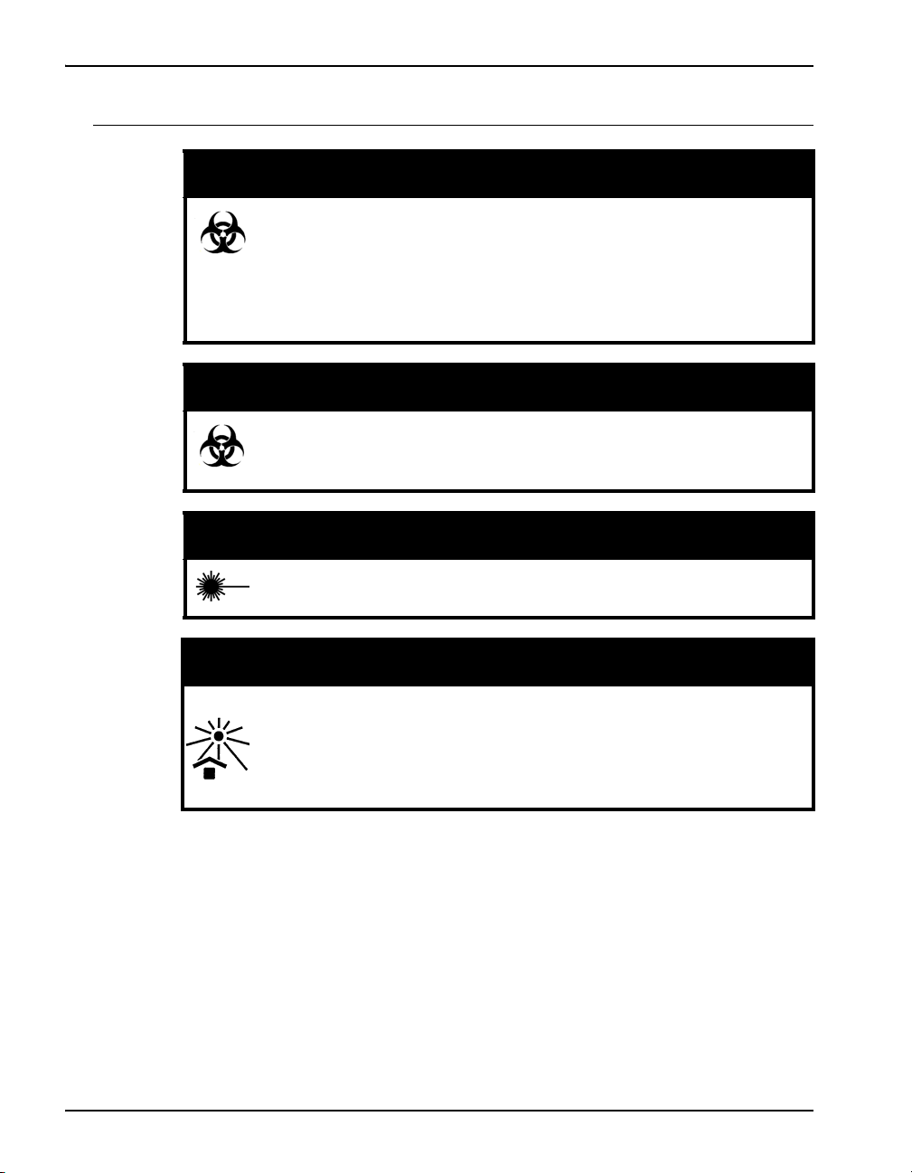
BIOHAZARD WARNING
This instrument may be involved with hazardous organism
suspensions. This user manual does not purport to address all
of the safety matters associated with the instrument’s use. It is
the responsibility of the user of this instrument to establish and
follow appropriate safety and health practices and to determine
the applicability of regulatory limitations prior to use.
BIOHAZARD WARNING
All organism suspensions should be considered as potentially
infectious. Qualified laboratory personnel should use
acceptable procedures for biohazardous material.
LASER WARNING
All access doors and covers must remain closed when
processing cards to avoid exposure to laser light.
AMBIENT LIGHT/DIRECT SUNLIGHT WARNING
The transmittance optics are sensitive to ambient light. Ensure
all access doors are closed when cards are processing in the
instrument. Do not place the instrument in direct sunlight.
Strong light shining onto the front of the instrument can cause
the optics to read incorrectly.
ii VITEK® 2 Instrument User Manual
510731-10EN1
Page 13

General Warnings
WARNING
This statement only applies to European countries with regard
to the waste electrical and electronic equipment European
directive:
You can play an important role in contributing to reuse,
recycling and other forms of recovery of waste electrical and
electronic equipment. Sorting this type of waste significantly
reduces potential negative effects on the environment and
human health as a result of the presence of hazardous
substances in electrical and electronic equipment.
At the end of the life cycle of this product, do not dispose of the
product as unsorted municipal waste, even if it is
decontaminated. It is imperative that you contact bioMérieux to
assure for its appropriate disposal.
VITEK® 2 Instrument User Manual iii
510731-10EN1
Page 14

General Warnings
Laser Caution
A laser caution label appears on the VITEK® 2 and VITEK® 2 XL at the
following locations:
VITEK® 2 VITEK® 2 XL
• on the front access door • on the left front access door
• on the inside panel behind the
• above the center front sliding door
front access door
• behind the waste collection door • behind the right side waste
collection door
The label appears as shown here:
CAUTION
Laser light when open.
DO NOT STARE INTO BEAM.
530520-2
iv VITEK® 2 Instrument User Manual
510731-10EN1
Page 15

TABLE OF CONTENTS
General Warnings ........................................................................................................i
General Warnings . . . . . . . . . . . . . . . . . . . . . . . . . . . . . . . . . . . . . . . . . . . . . . . . . ii
Laser Caution . . . . . . . . . . . . . . . . . . . . . . . . . . . . . . . . . . . . . . . . . . . . . . . . . . . .iv
List of Tables ............................................................................................................xiii
List of Figures ...........................................................................................................xv
How To Use This Manual........................................................................................ 1-1
Organization . . . . . . . . . . . . . . . . . . . . . . . . . . . . . . . . . . . . . . . . . . . . . . . . . . . 1-2
Documentation . . . . . . . . . . . . . . . . . . . . . . . . . . . . . . . . . . . . . . . . . . . . . . . . . 1-2
Intended Use. . . . . . . . . . . . . . . . . . . . . . . . . . . . . . . . . . . . . . . . . . . . . . . . . . . 1-2
How to Find Topics and Procedures. . . . . . . . . . . . . . . . . . . . . . . . . . . . . . . . . 1-3
Typographic and Usage Conventions. . . . . . . . . . . . . . . . . . . . . . . . . . . . . . . . 1-3
References . . . . . . . . . . . . . . . . . . . . . . . . . . . . . . . . . . . . . . . . . . . . . . . . 1-3
Graphical User Interface . . . . . . . . . . . . . . . . . . . . . . . . . . . . . . . . . . . . . . 1-3
Click . . . . . . . . . . . . . . . . . . . . . . . . . . . . . . . . . . . . . . . . . . . . . . . . . . . . . . . . . .1-3
Commands . . . . . . . . . . . . . . . . . . . . . . . . . . . . . . . . . . . . . . . . . . . . . . . . . . . . .1-3
Names and Titles . . . . . . . . . . . . . . . . . . . . . . . . . . . . . . . . . . . . . . . . . . . . . . . . 1-4
Press . . . . . . . . . . . . . . . . . . . . . . . . . . . . . . . . . . . . . . . . . . . . . . . . . . . . . . . . .1-4
Select . . . . . . . . . . . . . . . . . . . . . . . . . . . . . . . . . . . . . . . . . . . . . . . . . . . . . . . . . 1-4
Screen Text . . . . . . . . . . . . . . . . . . . . . . . . . . . . . . . . . . . . . . . . . . . . . . . . . . . .1-4
User Input . . . . . . . . . . . . . . . . . . . . . . . . . . . . . . . . . . . . . . . . . . . . . . . . . . . . . .1-4
Warnings, Cautions, and Information . . . . . . . . . . . . . . . . . . . . . . . . . . . . 1-5
Smart Carrier Station .............................................................................................. 2-1
Purpose. . . . . . . . . . . . . . . . . . . . . . . . . . . . . . . . . . . . . . . . . . . . . . . . . . . . . . . 2-2
Unpacking Instructions . . . . . . . . . . . . . . . . . . . . . . . . . . . . . . . . . . . . . . . . . . . 2-2
Unpacking Procedure . . . . . . . . . . . . . . . . . . . . . . . . . . . . . . . . . . . . . . . . 2-3
Installation Procedure . . . . . . . . . . . . . . . . . . . . . . . . . . . . . . . . . . . . . . . . 2-4
Preparations for Operation . . . . . . . . . . . . . . . . . . . . . . . . . . . . . . . . . . . . . . . . 2-5
Smart Carrier Station Overview . . . . . . . . . . . . . . . . . . . . . . . . . . . . . . . . . . . . 2-6
SCS Keyboard . . . . . . . . . . . . . . . . . . . . . . . . . . . . . . . . . . . . . . . . . . . . . . . . . 2-8
SCS Base Unit . . . . . . . . . . . . . . . . . . . . . . . . . . . . . . . . . . . . . . . . . . . . . . . . . 2-9
System Physical and Electrical Requirements . . . . . . . . . . . . . . . . . . . . . . . . . 2-9
Setup Bar Codes. . . . . . . . . . . . . . . . . . . . . . . . . . . . . . . . . . . . . . . . . . . . . . . 2-10
SCS Configuration .................................................................................................. 3-1
Configuration Overview. . . . . . . . . . . . . . . . . . . . . . . . . . . . . . . . . . . . . . . . . . . 3-2
VITEK® 2 Instrument User Manual v
510731-10EN1
Page 16

Table of Contents
When to Configure . . . . . . . . . . . . . . . . . . . . . . . . . . . . . . . . . . . . . . . . . . . 3-2
Accessing Configuration Screens . . . . . . . . . . . . . . . . . . . . . . . . . . . . . . . . 3-3
SCS Main Configuration Options . . . . . . . . . . . . . . . . . . . . . . . . . . . . . . . . . . . . 3-3
Cassette ID . . . . . . . . . . . . . . . . . . . . . . . . . . . . . . . . . . . . . . . . . . . . . . . . . 3-3
Setting Cassette ID. . . . . . . . . . . . . . . . . . . . . . . . . . . . . . . . . . . . . . . . . . . . . . .3-4
Setup Technologist ID. . . . . . . . . . . . . . . . . . . . . . . . . . . . . . . . . . . . . . . . . 3-4
Setting Setup Technologist ID . . . . . . . . . . . . . . . . . . . . . . . . . . . . . . . . . . . . . .3-4
Bench Name . . . . . . . . . . . . . . . . . . . . . . . . . . . . . . . . . . . . . . . . . . . . . . . . 3-4
Setting Bench Name. . . . . . . . . . . . . . . . . . . . . . . . . . . . . . . . . . . . . . . . . . . . . .3-4
SCS Workflow Configuration Options . . . . . . . . . . . . . . . . . . . . . . . . . . . . . . . . 3-5
AST Dilution Mode . . . . . . . . . . . . . . . . . . . . . . . . . . . . . . . . . . . . . . . . . . . 3-5
Setting AST Dilution Mode . . . . . . . . . . . . . . . . . . . . . . . . . . . . . . . . . . . . . . . . .3-5
Erase Cassette . . . . . . . . . . . . . . . . . . . . . . . . . . . . . . . . . . . . . . . . . . . . . . 3-6
Setting Cassette Erase . . . . . . . . . . . . . . . . . . . . . . . . . . . . . . . . . . . . . . . . . . . .3-6
Begin Data Entry. . . . . . . . . . . . . . . . . . . . . . . . . . . . . . . . . . . . . . . . . . . . . 3-6
Setting Begin Data Entry . . . . . . . . . . . . . . . . . . . . . . . . . . . . . . . . . . . . . . . . . .3-6
SCS Utilities . . . . . . . . . . . . . . . . . . . . . . . . . . . . . . . . . . . . . . . . . . . . . . . . . . . . 3-7
Language . . . . . . . . . . . . . . . . . . . . . . . . . . . . . . . . . . . . . . . . . . . . . . . . . . 3-7
Setting SCS Language . . . . . . . . . . . . . . . . . . . . . . . . . . . . . . . . . . . . . . . . . . . .3-7
Audible Feedback . . . . . . . . . . . . . . . . . . . . . . . . . . . . . . . . . . . . . . . . . . . . 3-8
Setting Audible Feedback. . . . . . . . . . . . . . . . . . . . . . . . . . . . . . . . . . . . . . . . . .3-8
Host Type . . . . . . . . . . . . . . . . . . . . . . . . . . . . . . . . . . . . . . . . . . . . . . . . . . 3-8
Changing Host Type . . . . . . . . . . . . . . . . . . . . . . . . . . . . . . . . . . . . . . . . . . . . . .3-8
Time and Date . . . . . . . . . . . . . . . . . . . . . . . . . . . . . . . . . . . . . . . . . . . . . . 3-8
Setting SCS Time and Date . . . . . . . . . . . . . . . . . . . . . . . . . . . . . . . . . . . . . . . .3-8
SCS Firmware Update . . . . . . . . . . . . . . . . . . . . . . . . . . . . . . . . . . . . . . . . . . . . 3-9
®
VITEK
2 Instrument ............................................................................................... 4-1
External Instrument Components. . . . . . . . . . . . . . . . . . . . . . . . . . . . . . . . . . . . 4-2
Controls, Access Doors and Connections . . . . . . . . . . . . . . . . . . . . . . . . . 4-3
Connections . . . . . . . . . . . . . . . . . . . . . . . . . . . . . . . . . . . . . . . . . . . . . . . . 4-4
Turning on the VITEK
®
2 Instrument . . . . . . . . . . . . . . . . . . . . . . . . . . . . . . . . . 4-4
Startup Procedure. . . . . . . . . . . . . . . . . . . . . . . . . . . . . . . . . . . . . . . . . . . . 4-4
Instrument Hardware Components . . . . . . . . . . . . . . . . . . . . . . . . . . . . . . . . . . 4-5
Smart Carrier Station (SCS) . . . . . . . . . . . . . . . . . . . . . . . . . . . . . . . . . . . . 4-5
Cassettes . . . . . . . . . . . . . . . . . . . . . . . . . . . . . . . . . . . . . . . . . . . . . . . . . . 4-6
Cassette Load and Unload Station . . . . . . . . . . . . . . . . . . . . . . . . . . . . . . . 4-7
Boats. . . . . . . . . . . . . . . . . . . . . . . . . . . . . . . . . . . . . . . . . . . . . . . . . . . . . . 4-8
Bar Code Reader . . . . . . . . . . . . . . . . . . . . . . . . . . . . . . . . . . . . . . . . . . . . 4-9
Button Memory Reader . . . . . . . . . . . . . . . . . . . . . . . . . . . . . . . . . . . . . . . 4-10
Dispenser/Pipettor Station . . . . . . . . . . . . . . . . . . . . . . . . . . . . . . . . . . . . 4-11
Dispenser . . . . . . . . . . . . . . . . . . . . . . . . . . . . . . . . . . . . . . . . . . . . . . . . . . . . .4-11
vi VITEK® 2 Instrument User Manual
510731-10EN1
Page 17

Table of Contents
Pipettor . . . . . . . . . . . . . . . . . . . . . . . . . . . . . . . . . . . . . . . . . . . . . . . . . . . . . . .4-12
Displacement Pump Operation. . . . . . . . . . . . . . . . . . . . . . . . . . . . . . . . . . . . . 4-13
Filler Station. . . . . . . . . . . . . . . . . . . . . . . . . . . . . . . . . . . . . . . . . . . . . . . 4-13
Sealer Station . . . . . . . . . . . . . . . . . . . . . . . . . . . . . . . . . . . . . . . . . . . . . 4-14
Test Card Incubation and Reading . . . . . . . . . . . . . . . . . . . . . . . . . . . . . 4-14
Carousel . . . . . . . . . . . . . . . . . . . . . . . . . . . . . . . . . . . . . . . . . . . . . . . . . 4-15
Optics. . . . . . . . . . . . . . . . . . . . . . . . . . . . . . . . . . . . . . . . . . . . . . . . . . . . 4-16
Transmittance Optics . . . . . . . . . . . . . . . . . . . . . . . . . . . . . . . . . . . . . . . . . . . . 4-16
Card Ejection . . . . . . . . . . . . . . . . . . . . . . . . . . . . . . . . . . . . . . . . . . . . . . 4-16
Waste Collection Station . . . . . . . . . . . . . . . . . . . . . . . . . . . . . . . . . . . . . 4-17
User Interface System . . . . . . . . . . . . . . . . . . . . . . . . . . . . . . . . . . . . . . . . . . 4-18
Keypad and Screen . . . . . . . . . . . . . . . . . . . . . . . . . . . . . . . . . . . . . . . . . 4-18
Configuring the VITEK
®
2 Instrument ................................................................... 5-1
Configuration Options . . . . . . . . . . . . . . . . . . . . . . . . . . . . . . . . . . . . . . . . . . . . 5-2
Configuration Overview . . . . . . . . . . . . . . . . . . . . . . . . . . . . . . . . . . . . . . . 5-2
Setting Configuration Options . . . . . . . . . . . . . . . . . . . . . . . . . . . . . . . . . . 5-2
Cassette Names . . . . . . . . . . . . . . . . . . . . . . . . . . . . . . . . . . . . . . . . . . . . 5-3
Instrument Name . . . . . . . . . . . . . . . . . . . . . . . . . . . . . . . . . . . . . . . . . . . . 5-3
Schedule Instrument QC Status . . . . . . . . . . . . . . . . . . . . . . . . . . . . . . . . 5-4
Cassette Mode. . . . . . . . . . . . . . . . . . . . . . . . . . . . . . . . . . . . . . . . . . . . . . 5-5
Dilution Mode. . . . . . . . . . . . . . . . . . . . . . . . . . . . . . . . . . . . . . . . . . . . . . . 5-5
Bar Code Reader. . . . . . . . . . . . . . . . . . . . . . . . . . . . . . . . . . . . . . . . . . . . 5-6
Audible Alarm Enable . . . . . . . . . . . . . . . . . . . . . . . . . . . . . . . . . . . . . . . . 5-6
Audible Alarm Volume . . . . . . . . . . . . . . . . . . . . . . . . . . . . . . . . . . . . . . . . 5-6
Visual Alarm Enable . . . . . . . . . . . . . . . . . . . . . . . . . . . . . . . . . . . . . . . . . 5-7
Audible Feedback Volume. . . . . . . . . . . . . . . . . . . . . . . . . . . . . . . . . . . . . 5-7
Screen Contrast. . . . . . . . . . . . . . . . . . . . . . . . . . . . . . . . . . . . . . . . . . . . . 5-7
Waste Tray Warning Level . . . . . . . . . . . . . . . . . . . . . . . . . . . . . . . . . . . . 5-8
Using the Interface . . . . . . . . . . . . . . . . . . . . . . . . . . . . . . . . . . . . . . . . . . . . . . 5-8
Defining Character Sets. . . . . . . . . . . . . . . . . . . . . . . . . . . . . . . . . . . . . . . 5-9
Setting Time for QC Status . . . . . . . . . . . . . . . . . . . . . . . . . . . . . . . . . . . 5-10
Using Option Boxes . . . . . . . . . . . . . . . . . . . . . . . . . . . . . . . . . . . . . . . . . 5-11
Setting a Range Value. . . . . . . . . . . . . . . . . . . . . . . . . . . . . . . . . . . . . . . 5-12
®
Processing VITEK
2 Test Cards........................................................................... 6-1
Instrument Status Screen . . . . . . . . . . . . . . . . . . . . . . . . . . . . . . . . . . . . . . . . . 6-3
Displaying the Status Screen. . . . . . . . . . . . . . . . . . . . . . . . . . . . . . . . . . . 6-3
Instrument Status Field . . . . . . . . . . . . . . . . . . . . . . . . . . . . . . . . . . . . . . . 6-3
Non Standard Card Reading Mode . . . . . . . . . . . . . . . . . . . . . . . . . . . . . . 6-4
Card Capacity . . . . . . . . . . . . . . . . . . . . . . . . . . . . . . . . . . . . . . . . . . . . . . 6-4
Cassette Name Field . . . . . . . . . . . . . . . . . . . . . . . . . . . . . . . . . . . . . . . . . 6-5
VITEK® 2 Instrument User Manual vii
510731-10EN1
Page 18

Table of Contents
Dilution Mode Indicator . . . . . . . . . . . . . . . . . . . . . . . . . . . . . . . . . . . . . . . . 6-5
Status Screen Icons . . . . . . . . . . . . . . . . . . . . . . . . . . . . . . . . . . . . . . . . . . 6-5
Monitoring Pipette Tips and Saline . . . . . . . . . . . . . . . . . . . . . . . . . . . . . . . 6-6
®
VITEK
2 Menu System . . . . . . . . . . . . . . . . . . . . . . . . . . . . . . . . . . . . . . . 6-7
Frequently Used Keys. . . . . . . . . . . . . . . . . . . . . . . . . . . . . . . . . . . . . . . . . 6-9
About the Smart Carrier Station (SCS) . . . . . . . . . . . . . . . . . . . . . . . . . . . . . . . 6-9
Advantages of Using SCS . . . . . . . . . . . . . . . . . . . . . . . . . . . . . . . . . . . . . 6-9
Cassette Edit Screen . . . . . . . . . . . . . . . . . . . . . . . . . . . . . . . . . . . . . . . . 6-11
Understanding the Slot Indicator. . . . . . . . . . . . . . . . . . . . . . . . . . . . . . . . 6-12
SCS Functions . . . . . . . . . . . . . . . . . . . . . . . . . . . . . . . . . . . . . . . . . . . . . 6-13
Option Boxes . . . . . . . . . . . . . . . . . . . . . . . . . . . . . . . . . . . . . . . . . . . . . . 6-14
Organism ID . . . . . . . . . . . . . . . . . . . . . . . . . . . . . . . . . . . . . . . . . . . . . . . . . . .6-14
Gram Positive Susceptibility Card . . . . . . . . . . . . . . . . . . . . . . . . . . . . . . . . . .6-14
Offline Test Result Screen . . . . . . . . . . . . . . . . . . . . . . . . . . . . . . . . . . . . 6-14
ANC Identification Card . . . . . . . . . . . . . . . . . . . . . . . . . . . . . . . . . . . . . . . . . .6-15
Offline Test Result Screen . . . . . . . . . . . . . . . . . . . . . . . . . . . . . . . . . . . . 6-15
Gram. . . . . . . . . . . . . . . . . . . . . . . . . . . . . . . . . . . . . . . . . . . . . . . . . . . . .6-15
Morphology. . . . . . . . . . . . . . . . . . . . . . . . . . . . . . . . . . . . . . . . . . . . . . . .6-15
Aerotolerance . . . . . . . . . . . . . . . . . . . . . . . . . . . . . . . . . . . . . . . . . . . . . .6-15
Modifier . . . . . . . . . . . . . . . . . . . . . . . . . . . . . . . . . . . . . . . . . . . . . . . . . . . . . . .6-16
Selecting an Entry Using an Option Box. . . . . . . . . . . . . . . . . . . . . . . . . . . . . .6-16
Bar Code Scanner . . . . . . . . . . . . . . . . . . . . . . . . . . . . . . . . . . . . . . . . . . 6-16
Processing Test Cards Using the Smart Carrier Station . . . . . . . . . . . . . . . . . 6-16
Configuration Options for Smart Carrier Workflow . . . . . . . . . . . . . . . . . . 6-16
Smart Carrier Workflow. . . . . . . . . . . . . . . . . . . . . . . . . . . . . . . . . . . . . . . 6-17
Entering Test Information With SCS . . . . . . . . . . . . . . . . . . . . . . . . . . . . . 6-17
Correct Positioning of AST Cards. . . . . . . . . . . . . . . . . . . . . . . . . . . . . . . . . . .6-18
Loading a Cassette . . . . . . . . . . . . . . . . . . . . . . . . . . . . . . . . . . . . . . . . . . 6-19
Using the Cassette Load Station . . . . . . . . . . . . . . . . . . . . . . . . . . . . . . . . . . .6-19
Loading a Cassette. . . . . . . . . . . . . . . . . . . . . . . . . . . . . . . . . . . . . . . . . . . . . .6-20
Monitoring Card Processing . . . . . . . . . . . . . . . . . . . . . . . . . . . . . . . . . . . . . . .6-20
Tracking Cassettes and Cards . . . . . . . . . . . . . . . . . . . . . . . . . . . . . . . . . . . . .6-21
Processing Test Cards in Cassette Only Mode . . . . . . . . . . . . . . . . . . . . . . . . 6-21
Configuration Options in Cassette Only Mode . . . . . . . . . . . . . . . . . . . . . 6-21
Cassette Only Mode Workflow . . . . . . . . . . . . . . . . . . . . . . . . . . . . . . . . . 6-21
Cassette Preparation . . . . . . . . . . . . . . . . . . . . . . . . . . . . . . . . . . . . . . . . 6-22
Printing a Cassette Worksheet . . . . . . . . . . . . . . . . . . . . . . . . . . . . . . . . . . . . .6-22
Using the Cassette Worksheet . . . . . . . . . . . . . . . . . . . . . . . . . . . . . . . . . . . . .6-22
Correct Positioning of Susceptibility Test Cards. . . . . . . . . . . . . . . . . . . . . . . .6-24
Using the Cassette Setup Function . . . . . . . . . . . . . . . . . . . . . . . . . . . . . . . . .6-24
Loading a Cassette . . . . . . . . . . . . . . . . . . . . . . . . . . . . . . . . . . . . . . . . . 6-25
Using the Cassette Load Station . . . . . . . . . . . . . . . . . . . . . . . . . . . . . . . . . . .6-26
Loading a Cassette. . . . . . . . . . . . . . . . . . . . . . . . . . . . . . . . . . . . . . . . . . . . . .6-26
Monitoring Test Card Processing . . . . . . . . . . . . . . . . . . . . . . . . . . . . . . . . . . .6-27
Entering Data for a Cassette. . . . . . . . . . . . . . . . . . . . . . . . . . . . . . . . . . . 6-27
viii VITEK® 2 Instrument User Manual
510731-10EN1
Page 19

Table of Contents
Tracking Cassettes and Cards . . . . . . . . . . . . . . . . . . . . . . . . . . . . . . . . . . . . .6-27
Batch Loads (Smart Carrier or Cassette Only Mode) . . . . . . . . . . . . . . . . . . . 6-28
Selecting Batch Loading . . . . . . . . . . . . . . . . . . . . . . . . . . . . . . . . . . . . . 6-28
Before You Begin . . . . . . . . . . . . . . . . . . . . . . . . . . . . . . . . . . . . . . . . . . . . . . .6-28
Starting a Batch Load . . . . . . . . . . . . . . . . . . . . . . . . . . . . . . . . . . . . . . . 6-28
Unloading the Cassette and Removing Waste . . . . . . . . . . . . . . . . . . . . . . . . 6-30
Unloading a Cassette . . . . . . . . . . . . . . . . . . . . . . . . . . . . . . . . . . . . . . . 6-30
Removing Ejected Test Cards . . . . . . . . . . . . . . . . . . . . . . . . . . . . . . . . . 6-31
Removing the Waste Collection Tray . . . . . . . . . . . . . . . . . . . . . . . . . . . . . . . .6-32
Replacing the Waste Collection Tray . . . . . . . . . . . . . . . . . . . . . . . . . . . . . . . .6-32
Maintaining the VITEK® 2 Instrument.................................................................... 7-1
Maintaining Disposables . . . . . . . . . . . . . . . . . . . . . . . . . . . . . . . . . . . . . . . . . . 7-3
Monitoring the Disposables . . . . . . . . . . . . . . . . . . . . . . . . . . . . . . . . . . . . 7-3
Interpreting the Graphs. . . . . . . . . . . . . . . . . . . . . . . . . . . . . . . . . . . . . . . . . . . . 7-3
Using the Graphs . . . . . . . . . . . . . . . . . . . . . . . . . . . . . . . . . . . . . . . . . . . . . . . . 7-4
Expiration of Disposables . . . . . . . . . . . . . . . . . . . . . . . . . . . . . . . . . . . . . . . . . .7-4
The Dispenser/Pipettor Accessory Kit . . . . . . . . . . . . . . . . . . . . . . . . . . . . 7-4
Installing an Accessory Kit, Part A: Saline and Tubing . . . . . . . . . . . . . . . 7-4
Installing an Accessory Kit, Part B: Pipette Tips . . . . . . . . . . . . . . . . . . . . 7-8
Cleaning the Carousel . . . . . . . . . . . . . . . . . . . . . . . . . . . . . . . . . . . . . . . . . . 7-10
Removing the Carousel for Cleaning. . . . . . . . . . . . . . . . . . . . . . . . . . . . 7-10
Carousel Cleaning Methods . . . . . . . . . . . . . . . . . . . . . . . . . . . . . . . . . . 7-15
Replacing the Carousel After Cleaning . . . . . . . . . . . . . . . . . . . . . . . . . . 7-15
Cleaning the Cassettes. . . . . . . . . . . . . . . . . . . . . . . . . . . . . . . . . . . . . . . . . . 7-19
Replacing the Button Memory Module. . . . . . . . . . . . . . . . . . . . . . . . . . . 7-20
Cleaning the Boats . . . . . . . . . . . . . . . . . . . . . . . . . . . . . . . . . . . . . . . . . . . . . 7-21
Removing Boats for Cleaning . . . . . . . . . . . . . . . . . . . . . . . . . . . . . . . . . 7-21
Cleaning the Boats . . . . . . . . . . . . . . . . . . . . . . . . . . . . . . . . . . . . . . . . . 7-23
Replacing Boats after Cleaning . . . . . . . . . . . . . . . . . . . . . . . . . . . . . . . . 7-23
Cleaning the Instrument Interior . . . . . . . . . . . . . . . . . . . . . . . . . . . . . . . . . . . 7-24
Shutting Down the Instrument . . . . . . . . . . . . . . . . . . . . . . . . . . . . . . . . . 7-25
Cleaning the Test Card Collection Tray . . . . . . . . . . . . . . . . . . . . . . . . . . 7-25
Cleaning Optics (Normal Maintenance). . . . . . . . . . . . . . . . . . . . . . . . . . 7-26
Cleaning the Base Pan, Vacuum Seal and Vacuum Chamber . . . . . . . . 7-28
Cleaning the Drip Pan . . . . . . . . . . . . . . . . . . . . . . . . . . . . . . . . . . . . . . . . . . 7-29
Removing the Drip Pan . . . . . . . . . . . . . . . . . . . . . . . . . . . . . . . . . . . . . . 7-30
Cleaning the Drip Pan . . . . . . . . . . . . . . . . . . . . . . . . . . . . . . . . . . . . . . . 7-30
Replacing the Drip Pan . . . . . . . . . . . . . . . . . . . . . . . . . . . . . . . . . . . . . . 7-31
Turning the Instrument On. . . . . . . . . . . . . . . . . . . . . . . . . . . . . . . . . . . . 7-31
Cleaning the SCS . . . . . . . . . . . . . . . . . . . . . . . . . . . . . . . . . . . . . . . . . . . . . . 7-32
VITEK® 2 Instrument User Manual ix
510731-10EN1
Page 20

Table of Contents
Troubleshooting the VITEK® 2 Instrument ........................................................... 8-1
Error Handling System . . . . . . . . . . . . . . . . . . . . . . . . . . . . . . . . . . . . . . . . . . . . 8-3
Error Alarms . . . . . . . . . . . . . . . . . . . . . . . . . . . . . . . . . . . . . . . . . . . . . . . . 8-4
Types of Errors . . . . . . . . . . . . . . . . . . . . . . . . . . . . . . . . . . . . . . . . . . . . . . 8-4
Status Screen Error Conditions . . . . . . . . . . . . . . . . . . . . . . . . . . . . . . . . . . . . . 8-4
Instrument Halted Screen . . . . . . . . . . . . . . . . . . . . . . . . . . . . . . . . . . . . . . 8-5
Reviewing an Instrument Halted Screen . . . . . . . . . . . . . . . . . . . . . . . . . . . . . .8-6
Resolving a Transport Halted Screen. . . . . . . . . . . . . . . . . . . . . . . . . . . . . . . . .8-6
Message Status Screen . . . . . . . . . . . . . . . . . . . . . . . . . . . . . . . . . . . . . . . 8-8
Reviewing a Message Status Screen . . . . . . . . . . . . . . . . . . . . . . . . . . . . . . . . . 8-9
Error Status Screen . . . . . . . . . . . . . . . . . . . . . . . . . . . . . . . . . . . . . . . . . 8-10
Reviewing an Error Status Screen . . . . . . . . . . . . . . . . . . . . . . . . . . . . . . . . . .8-10
Cassette Load Processing Errors . . . . . . . . . . . . . . . . . . . . . . . . . . . . . . . . . . 8-10
Types of Errors . . . . . . . . . . . . . . . . . . . . . . . . . . . . . . . . . . . . . . . . . . . . . 8-10
Workflow Considerations . . . . . . . . . . . . . . . . . . . . . . . . . . . . . . . . . . . . . 8-11
Bar Code Read Failure . . . . . . . . . . . . . . . . . . . . . . . . . . . . . . . . . . . . . . . 8-11
Resolving Bar Code Read Errors . . . . . . . . . . . . . . . . . . . . . . . . . . . . . . . . . . .8-11
SCS and Bar Code Reader Conflict . . . . . . . . . . . . . . . . . . . . . . . . . . . . . 8-13
Resolving SCS and Bar Code Reader Conflicts. . . . . . . . . . . . . . . . . . . . . . . .8-13
Inoculum Errors. . . . . . . . . . . . . . . . . . . . . . . . . . . . . . . . . . . . . . . . . . . . . 8-14
Resolving an Inoculum Error . . . . . . . . . . . . . . . . . . . . . . . . . . . . . . . . . . . . . .8-15
Card Capacity Errors . . . . . . . . . . . . . . . . . . . . . . . . . . . . . . . . . . . . . . . . 8-16
Resolving a Card Capacity Error . . . . . . . . . . . . . . . . . . . . . . . . . . . . . . . . . . .8-16
Disposables Errors . . . . . . . . . . . . . . . . . . . . . . . . . . . . . . . . . . . . . . . . . . 8-17
How to Resolve a Disposables Error . . . . . . . . . . . . . . . . . . . . . . . . . . . . . . . .8-17
Working Without the Bar Code Reader . . . . . . . . . . . . . . . . . . . . . . . . . . . . . . 8-17
Entering Bar Codes Manually . . . . . . . . . . . . . . . . . . . . . . . . . . . . . . . . . . 8-17
Disabling the Bar Code Reader . . . . . . . . . . . . . . . . . . . . . . . . . . . . . . . . . . . .8-17
Entering Bar Codes Manually . . . . . . . . . . . . . . . . . . . . . . . . . . . . . . . . . . . . . .8-18
Instrument Diagnostics. . . . . . . . . . . . . . . . . . . . . . . . . . . . . . . . . . . . . . . . . . . 8-18
Instrument Diagnostics Menu . . . . . . . . . . . . . . . . . . . . . . . . . . . . . . . . . . 8-18
Diagnostic Tests . . . . . . . . . . . . . . . . . . . . . . . . . . . . . . . . . . . . . . . . . . . . 8-19
Checking the Instrument Temperature . . . . . . . . . . . . . . . . . . . . . . . . . . . . . . .8-19
Dispenser/Pipettor Diagnostic Test . . . . . . . . . . . . . . . . . . . . . . . . . . . . . . . . .8-20
Dispenser/Pipettor Volumetric Test . . . . . . . . . . . . . . . . . . . . . . . . . . . . . . . . .8-21
Cleaning Optics (Cards Processing) . . . . . . . . . . . . . . . . . . . . . . . . . . . . . . . . 8-23
Optical Diagnostic Test . . . . . . . . . . . . . . . . . . . . . . . . . . . . . . . . . . . . . . . 8-26
Boat Transport Positions . . . . . . . . . . . . . . . . . . . . . . . . . . . . . . . . . . . . . . . . . 8-26
Power Failures . . . . . . . . . . . . . . . . . . . . . . . . . . . . . . . . . . . . . . . . . . . . . . . . . 8-28
Displaying Version Information . . . . . . . . . . . . . . . . . . . . . . . . . . . . . . . . . . . . 8-28
Using Error Message and Recovery Table . . . . . . . . . . . . . . . . . . . . . . . . . . . 8-29
Restarting the Instrument . . . . . . . . . . . . . . . . . . . . . . . . . . . . . . . . . . . . . 8-29
x VITEK® 2 Instrument User Manual
510731-10EN1
Page 21

Table of Contents
Appendix A: Hardware Specifications ..................................................................A-1
®
VITEK
2 Instrument. . . . . . . . . . . . . . . . . . . . . . . . . . . . . . . . . . . . . . . . . . . . . A-1
Dimensions . . . . . . . . . . . . . . . . . . . . . . . . . . . . . . . . . . . . . . . . . . . . . . . . A-1
Mass . . . . . . . . . . . . . . . . . . . . . . . . . . . . . . . . . . . . . . . . . . . . . . . . . . . . . A-1
Environment. . . . . . . . . . . . . . . . . . . . . . . . . . . . . . . . . . . . . . . . . . . . . . . . A-2
Electrical Characteristics . . . . . . . . . . . . . . . . . . . . . . . . . . . . . . . . . . . . . . A-3
Optical Characteristics. . . . . . . . . . . . . . . . . . . . . . . . . . . . . . . . . . . . . . . . A-3
Transmittance Optics . . . . . . . . . . . . . . . . . . . . . . . . . . . . . . . . . . . . . . . . . . . . A-3
General Characteristics . . . . . . . . . . . . . . . . . . . . . . . . . . . . . . . . . . . . . . . A-4
Cassette . . . . . . . . . . . . . . . . . . . . . . . . . . . . . . . . . . . . . . . . . . . . . . . . . . . . . . A-4
Dispenser . . . . . . . . . . . . . . . . . . . . . . . . . . . . . . . . . . . . . . . . . . . . . . . . . . . . . A-4
Pipettor . . . . . . . . . . . . . . . . . . . . . . . . . . . . . . . . . . . . . . . . . . . . . . . . . . . . . . . A-4
Vacuum (Filler) . . . . . . . . . . . . . . . . . . . . . . . . . . . . . . . . . . . . . . . . . . . . . . . . . A-4
Sealer . . . . . . . . . . . . . . . . . . . . . . . . . . . . . . . . . . . . . . . . . . . . . . . . . . . . . . . . A-4
Incubator. . . . . . . . . . . . . . . . . . . . . . . . . . . . . . . . . . . . . . . . . . . . . . . . . . . . . . A-4
Glossary......................................................................................................Glossary-1
Index.................................................................................................................. Index-1
Notes ................................................................................................................ Notes-1
VITEK® 2 Instrument User Manual xi
510731-10EN1
Page 22

Table of Contents
xii VITEK® 2 Instrument User Manual
510731-10EN1
Page 23

LIST OF TABLES
Table 2-1: Physical Characteristics .....................................................................................2-9
Table 2-2: Electrical Requirements .....................................................................................2-9
Table 2-3: Environmental Requirements .............................................................................2-9
Table 2-4: Bar Code Scanner Model References .............................................................2-11
Table 3-1: SCS Configuration Options ................................................................................3-2
Table 4-1: Components Involved in the Test Card Processing Cycle .................................4-5
Table 4-2: Indicator Light States .........................................................................................4-7
Table 5-1: Configuration Options that Affect Instrument Operation ....................................5-2
Table 5-2: Configuration Options that Affect Only Physical Parameters .............................5-2
Table 5-3: Types of Interfaces for Configuration Options ...................................................5-8
Table 6-1: Optical Configurations ........................................................................................6-5
Table 6-2: Summary of SCS Functions .............................................................................6-13
Table 6-3: Processing Test Cards (Using the Smart Carrier) ............................................6-17
Table 6-4: Data Entry Methods (Smart Carrier Mode) ......................................................6-18
Table 6-5: Cassette Load Parameters (Smart Carrier Mode) ...........................................6-19
Table 6-6: Card Identity Components (Smart Carrier Mode) ............................................6-21
Table 6-7: Processing Test Cards (Cassette Only Mode) .................................................6-22
Table 6-8: Cassette Load Parameters (Cassette Only Mode) ..........................................6-25
Table 6-9: Card Identity Components (Cassette Only Mode) ...........................................6-27
Table 8-1: Dispenser/Pipettor Volumetric Test .................................................................8-22
Table 8-2: Error Message and Recovery Table ................................................................8-30
VITEK® 2 Instrument User Manual xiii
510731-10EN1
Page 24

List of Tables
xiv VITEK® 2 Instrument User Manual
510731-10EN1
Page 25

LIST OF FIGURES
Figure 2-1: Smart Carrier Station .........................................................................................2-2
Figure 2-2: SCS – Cable Connections .................................................................................2-4
Figure 2-3: Initial SCS Screen ..............................................................................................2-6
Figure 2-4: The Smart Carrier Station ..................................................................................2-7
Figure 2-5: The SCS Keyboard ............................................................................................2-8
Figure 2-6: SCS Firmware Update Screen .........................................................................2-10
Figure 2-7: Bar Codes for Bar Code Scanner – A ..............................................................2-13
Figure 2-8: Bar Codes for Bar Code Scanner – B ..............................................................2-14
Figure 2-9: Bar Codes for Bar Code Scanner – C ..............................................................2-15
Figure 2-10: Bar Codes for Bar Code Scanner – D ..............................................................2-16
Figure 3-1: SCS Main Configuration Screen ........................................................................3-3
Figure 3-2: SCS Workflow Configuration Screen .................................................................3-5
Figure 3-3: SCS Utilities Screen ...........................................................................................3-7
Figure 3-4: SCS Firmware Update Screen ...........................................................................3-9
Figure 4-1: The VITEK
Figure 4-2: VITEK® 2 XL Instrument ....................................................................................4-2
Figure 4-3: Cassette Components .......................................................................................4-6
Figure 4-4: The Cassette Load/Unload Station ....................................................................4-7
Figure 4-5: Boat Components ..............................................................................................4-9
Figure 4-6: Dispenser System ............................................................................................4-11
Figure 4-7: Disposable Pipettes .........................................................................................4-12
Figure 4-8: Carousel Placement .........................................................................................4-15
Figure 4-9: Carousel Reader Head ....................................................................................4-15
Figure 4-10: Optics ...............................................................................................................4-16
Figure 4-11: Waste Collection Station ..................................................................................4-17
Figure 4-12: The VITEK
Figure 5-1: The Instrument QC Status Screen .....................................................................5-4
Figure 5-2: VITEK® 2 Main Menu .........................................................................................5-9
Figure 5-3: Cassette Names Configuration Screen ..............................................................5-9
Figure 5-4: Character Selection Screen .............................................................................5-10
Figure 5-5: Schedule QC Status Screen ............................................................................5-11
®
2 60 Instrument .............................................................................4-2
®
2 Keypad and Screen ..................................................................4-18
VITEK® 2 Instrument User Manual xv
510731-10EN1
Page 26

List of Figures
Figure 5-6: Option Box Screen .......................................................................................... 5-12
Figure 5-7: Range Value Screen ....................................................................................... 5-12
Figure 6-1: VITEK
®
2 Status Screen in Cassette Only Mode .............................................. 6-3
Figure 6-2: VITEK® 2 Status Screen in Non Standard Card Reading Mode ....................... 6-4
Figure 6-3: Pipette Tips Status ............................................................................................ 6-7
Figure 6-4: VITEK
®
2 Main Menu ........................................................................................ 6-7
Figure 6-5: Detailed Structure of the VITEK® 2 Menu System ............................................ 6-8
Figure 6-6: Previous Screen Key ......................................................................................... 6-9
Figure 6-7: Fields of the Cassette Edit Screen .................................................................. 6-11
Figure 6-8: Organism ID Options ....................................................................................... 6-14
Figure 6-9: Offline Tests Option Box ................................................................................. 6-15
Figure 6-10: Offline Test Result Screen .............................................................................. 6-15
Figure 6-11: Correct Orientation of Cassettes ..................................................................... 6-20
Figure 6-12: Cassette Worksheet ........................................................................................ 6-23
Figure 6-13: Cassette Setup Screen ................................................................................... 6-24
Figure 6-14: Correct Orientation of Cassette ....................................................................... 6-26
Figure 6-15: Batch Load Screen .......................................................................................... 6-29
Figure 6-16: Smart Carrier Mode Batch Load Screen ......................................................... 6-29
Figure 6-17: Cassette Only Mode Batch Load Screen ........................................................ 6-30
Figure 6-18: The Waste Collection Station .......................................................................... 6-32
Figure 7-1: VITEK
®
2 Status Screen ................................................................................... 7-3
Figure 7-2: Location of Saline Dispensing Chamber ........................................................... 7-5
Figure 7-3: Cannula and Tubing Assembly ......................................................................... 7-6
Figure 7-4: Saline Dispensing Chamber .............................................................................. 7-6
Figure 7-5: Saline Fill Line ................................................................................................... 7-7
Figure 7-6: Location of Pipettor Tip Container ..................................................................... 7-8
Figure 7-7: Pipette Tip Replacement ................................................................................... 7-9
Figure 7-8: VITEK
Figure 7-9: VITEK
®
2 XL Carousel Cleaning Screen ........................................................ 7-11
®
2 XL Preparing for Section Removal Screen ..................................... 7-11
Figure 7-10: Machined Incubator Access Cover ................................................................. 7-12
Figure 7-11: Molded Incubator Access Cover ..................................................................... 7-13
Figure 7-12: Carousel Cleaning Prompt .............................................................................. 7-13
Figure 7-13: Removing a Carousel Section ......................................................................... 7-14
Figure 7-14: Machined Incubator Access Cover ................................................................. 7-16
xvi VITEK® 2 Instrument User Manual
510731-10EN1
Page 27

List of Figures
Figure 7-15: Molded Incubator Access Cover ......................................................................7-16
Figure 7-16: Carousel Cleaning Replace Section Now Screen ............................................7-17
Figure 7-17: Orientation of the Carousel ..............................................................................7-17
Figure 7-18: Removing the Button Memory Module .............................................................7-20
Figure 7-19: Metal Contacts on Cassette .............................................................................7-20
Figure 7-20: Replacing the Button Memory Module .............................................................7-21
Figure 7-21: Boat Cleaning Prompt ......................................................................................7-22
Figure 7-22: Positioning of Boat ...........................................................................................7-24
Figure 7-23: Optics ...............................................................................................................7-27
Figure 7-24: Opening the Optics ..........................................................................................7-27
Figure 7-25: Vacuum Seal ....................................................................................................7-29
Figure 7-26: Drip Pan Handle ...............................................................................................7-30
Figure 7-27: SCS Base Unit Metal Contacts ........................................................................7-32
Figure 8-1: VITEK
®
2 Error Handling System ......................................................................8-3
Figure 8-2: Instrument Halted Status Screen .......................................................................8-5
Figure 8-3: Transport Halted Screen (VITEK
®
2) .................................................................8-7
Figure 8-4: Transport Halted Screen (VITEK® 2 XL) ............................................................8-7
Figure 8-5: VITEK
®
2 Status Screen ....................................................................................8-8
Figure 8-6: Message Queue .................................................................................................8-9
Figure 8-7: Bar Code Error Message .................................................................................8-12
Figure 8-8: Resolving Bar Code Errors ..............................................................................8-12
Figure 8-9: Card Type Error Message ................................................................................8-14
Figure 8-10: Inoculum Source Error Message .....................................................................8-15
Figure 8-11: Card Capacity Warning Message ....................................................................8-16
Figure 8-12: Bar Code Reader Screen .................................................................................8-18
Figure 8-13: Temperature Diagnostics Screen (VITEK
Figure 8-14: Temperature Diagnostics Screen (VITEK
®
2 XL) ............................................8-19
®
2) ..................................................8-20
Figure 8-15: Optics ...............................................................................................................8-24
Figure 8-16: Opening the Optics ..........................................................................................8-25
Figure 8-17: Boat Transport Positions ..................................................................................8-27
Figure 8-18: Version Information Screen .............................................................................8-29
VITEK® 2 Instrument User Manual xvii
510731-10EN1
Page 28

List of Figures
xviii VITEK® 2 Instrument User Manual
510731-10EN1
Page 29

HOW TO USE THIS MANUAL
Introduction
This chapter gives you important information about how to use this manual.
bioMérieux recommends that you read this chapter first.
IMPORTANT: Read this manual carefully before you attempt to operate the VITEK®2
system.
Chapter Contents
Organization • 1-2
Printed Documentation • 1-2
Intended Use • 1-2
How to Find Topics and Procedures • 1-3
Typographic and Usage Conventions • 1-3
References • 1-3
Graphical User Interface • 1-3
Warnings, Cautions, and Information • 1-5
1
VITEK® 2 Instrument User Manual 1-1
510731-10EN1
Page 30

Organization How To Use This Manual
Organization
The manual is separated into four basic parts:
• Part 1, which includes Chapter 2 and Chapter 3, covers the Smart Carrier
Station. Chapter 2 describes the hardware and Chapter 3 provides the
procedures you use to configure this station for your laboratory workflow.
• Part 2, which includes Chapter 4 and Chapter 5, covers the VITEK
Instrument. Chapter 4 describes the hardware and Chapter 5 shows you
how to configure the instrument’s user interface.
®
2
• Part 3, including only Chapter 6, is the primary part of the manual. It
• Part 4, consisting of Chapter 7 and Chapter 8, provides troubleshooting
Documentation
The documentation for the VITEK® 2 system consists of this manual and
VITEK
that the computer workstation may be in a different location than the VITEK
2 instrument and Smart Carrier Station.
• This manual covers the VITEK
•The VITEK
Intended Use
describes all of the procedures you need to follow to process VITEK
®
2 test
cards. The chapter contains two subparts, one each to describe test card
processing with, and without, a Smart Carrier Station.
and maintenance procedures for the VITEK
®
2 Systems Product Information. This division allows for the possibility
®
2 instrument and the Smart Carrier
®
2 instrument.
Station, including both the hardware and the programmed user interfaces.
®
2 Systems Product Information contains information about the
test cards, including culture techniques, analytical techniques, and
performance characteristics.
®
The VITEK® 2 and Smart Carrier Station (SCS) have applications as in vitro
diagnostic medical devices.
1-2 VITEK® 2 Instrument User Manual
510731-10EN1
Page 31

How To Use This Manual How to Find Topics and Procedures
How to Find Topics and Procedures
There are four tools to help you find a topic or procedure in the manual.
• General Table of Contents. This table is located in the front of the manual
and includes the entire document. You can use this table to locate major
headings throughout the manual. The table also includes a List of Tables
and a List of Figures.
• Chapter Table of Contents. Each of the succeeding chapters begin with
their own tables of contents. They contain the same information as the
general table for the manual, but have the advantage of addressing only
what is in that chapter.
• Page Headers. Each page in the manual has a header, which can serve as
a visual aid to help you find a topic. The inside portion of the header, the
side closest to the binding, always shows the chapter title. The outside
portion of the header shows the title of the current section.
• Index. Found at the end of the manual, the Index is the most useful device
for finding individual topics throughout the manual.
Typographic and Usage Conventions
References
References to chapter and section titles in this manual are in Proper Case.
Example: See Chapter 5, Configuring the VITEK
References to other manuals are in Proper Case and italic font.
®
Example: See the VITEK
Graphical User Interface
Click
The term “click” refers to moving a mouse pointer to choose or select a
command, window, button or option, then pressing the left, or primary, mouse
button to initiate action in the software.
Example: Click OK
Commands
Menu, keyboard and button commands are in proper case, bold.
2 Systems Product Information.
®
2 Instrument.
VITEK® 2 Instrument User Manual 1-3
510731-10EN1
Page 32

Typographic and Usage Conventions How To Use This Manual
Example: File > Quit menu command
Names and Titles
The names and titles of menus, dialog boxes, fields, icons and toolbar
buttons are in proper case, bold.
Example: Setup menu
The names of windows are in proper case, but are not bold.
Example: Configuration window
Press
The term “press” refers to holding down a key on the keyboard in order to
initiate action in the software.
Example: Press Enter
Select
The word “select” is generally used for selecting menus, menu commands
and GUI navigation.
Screen Text
User Input
Example: Select File > Quit
Text that appears on the screen will be shown in a monotype font.
Example: Saline Test in Progress
Instructions for user input begin with the word “type” or “enter.” These
instructions use bold for literal user input and italic for placeholders.
Example of literal user input: Login as micb, and password micb
In this example, type exactly what you see on the page (micb in this
example).
Example of a placeholder: Enter your password before you...
In this example, type your assigned password.
1-4 VITEK® 2 Instrument User Manual
510731-10EN1
Page 33

How To Use This Manual Typographic and Usage Conventions
Warnings, Cautions, and Information
This manual uses different types of symbols to alert you to important
information. Symbols and their associated information are labeled in text
where they occur and set off from surrounding paragraphs, as shown in the
following examples.
WARNING
Warning is a statement that alerts the user to the possibility of
injury, death, or other serious adverse reactions associated
with the use or misuse of a device.
CAUTION: Caution is a statement that alerts the user to the
possibility of a problem with the device associated with its use
or misuse. Such problems include device malfunction, device
failure, damage to the device, or damage to other property.
Where applicable, a caution statement may include a precaution
that should be taken to avoid the hazard.
IMPORTANT: Important relates to content presented in this manual. It is used to
reinforce the importance of your understanding or remembering
something.
Note: Note supplies additional information about a topic.
VITEK® 2 Instrument User Manual 1-5
510731-10EN1
Page 34

Typographic and Usage Conventions How To Use This Manual
1-6 VITEK® 2 Instrument User Manual
510731-10EN1
Page 35

SMART CARRIER STATION
Introduction
Use this chapter to familiarize yourself with the Smart Carrier hardware. It
includes an overview of each part of the unit.
Chapter Contents
Purpose • 2-2
Unpacking Instructions • 2-2
Unpacking Procedure • 2-3
Installation Procedure • 2-4
Preparations for Operation • 2-5
Smart Carrier Station Overview • 2-6
SCS Keyboard • 2-8
SCS Base Unit • 2-9
System Physical and Electrical Requirements • 2-9
Setup Bar Codes • 2-10
2
VITEK® 2 Instrument User Manual 2-1
510731-10EN1
Page 36

Purpose Smart Carrier Station
Purpose
The purpose of this chapter is to aid in the safe handling, setup, configuration
and operation of the Smart Carrier Station.
Unpacking Instructions
Figure 2-1 shows a Smart Carrier Station (SCS).
1
2
1 — Display Screen
4
3
5
Figure 2-1: Smart Carrier Station
2 — Power Supply
3 — Base Unit
4 — Bar Code Scanner
5 — Keyboard
2-2 VITEK® 2 Instrument User Manual
510731-10EN1
Page 37

Smart Carrier Station Unpacking Instructions
Inspect the shipping container for external damage. If it has been damaged,
inspect the SCS itself for damage. If the SCS has been damaged, file a claim
with the shipper and notify bioMérieux, Inc.
Check the packing list included with the VITEK
required items are included in the shipment.
Note: The packaging materials and shipping container should be retained for future
transportation needs, if necessary.
®
2 System and verify that all
WARNING
This statement only applies to European countries with regard
to the waste electrical and electronic equipment European
directive:
You can play an important role in contributing to reuse,
recycling and other forms of recovery of waste electrical and
electronic equipment. Sorting this type of waste significantly
reduces potential negative effects on the environment and
human health as a result of the presence of hazardous
substances in electric and electronic equipment.
At the end of the life cycle of this product, do not dispose of the
product as unsorted municipal waste, even if it is
decontaminated. It is imperative that you contact bioMérieux to
assure for it’s proper disposal.
Unpacking Procedure
To remove the SCS from its shipping container:
1) Open the shipping carton and remove the unit from the carton.
2) Carefully remove the unit from the packing material. Be sure to remove
all parts and literature from the carton.
3) Remove the remaining packing materials from the SCS and store with
the shipping container.
An electric shock hazard could exist if the enclosure of the SCS
or its external power supply is damaged exposing electrical
components.
WARNING
VITEK® 2 Instrument User Manual 2-3
510731-10EN1
Page 38

Unpacking Instructions Smart Carrier Station
Installation Procedure
After completing the unpacking procedure, the SCS is ready to be placed in
its permanent location. The SCS is intended for use on any normal, flat bench
top, commonly found in a microbiology lab, away from direct sunlight. Some
cables must be connected to the unit. Figure 2-2 shows the cable
connections on the back of the unit.
1
2
3
4
5
Figure 2-2: SCS – Cable Connections
The back panel of the base unit, shown in Figure 2-2, contains the on/off
switch, the power cord receptacle, and the connector ports for various cables.
1 — On/Off Switch
2 — DC Power Receptacle
3 — Receptacle for the Bar Code Scanner
4 — Circular Connector for the SCS Keyboard
5 — Service/Update Cable Connector
2-4 VITEK® 2 Instrument User Manual
510731-10EN1
Page 39

Smart Carrier Station Preparations for Operation
Preparations for Operation
Place the SCS in its permanent location.
WARNING
Do not place the SCS in a location where it could be exposed to
direct sunlight during operation.
Position the instrument to meet the minimum clearance of 5 cm (2 in.) on all
sides and 30.5 cm (12 in.) above the instrument to provide adequate space
for placing cassettes onto the unit.
Use this procedure to begin using the SCS. The unit should be located on a
bench top with room next to it for test cards and specimens. Use Figure 2-2 of
the SCS to locate and identify the various parts referred to in the procedure.
WARNING
An electric shock hazard could exist if the SCS or its external
power supply is immersed in water.
1) Connect the SCS keyboard to its receptacle (4, Figure 2-2) on the back
of the base unit.
2) Connect the bar code scanner to its receptacle (3) on the back of the
base unit.
3) Connect the external power supply cord to the back of the SCS (2) and
the main cord to an AC power outlet.
4) Push the On/Off switch (1) to turn the unit on. The computer takes a few
moments to go through its startup routine.
VITEK® 2 Instrument User Manual 2-5
510731-10EN1
Page 40

Smart Carrier Station Overview Smart Carrier Station
Figure 2-3: Initial SCS Screen
5) When the SCS is ready to be used, the screen shown in Figure 2-3 will
be displayed. If there is no display, switch the power OFF and restart at
Step 2.
Note: If you have not yet customized your configuration settings, the Configuration
screen is displayed. For information on changing the settings, see Chapter 3
in this Manual.
Smart Carrier Station Overview
The Smart Carrier Station (SCS) is a small computer dedicated to collecting
information about test cards and specimens, and for transferring that
information to the VITEK
five main components.
®
2 instrument. The SCS, shown in Figure 2-4, has
2-6 VITEK® 2 Instrument User Manual
510731-10EN1
Page 41

Smart Carrier Station Smart Carrier Station Overview
3
2
1
5
Figure 2-4: The Smart Carrier Station
1 — SCS Base Unit. The SCS base contains the microprocessor. There are
connection ports on the back of the base for the keyboard and the bar code
scanner. The top of the base is specifically shaped to accept a cassette.
Metal contacts on the base connect the unit’s computer to a button memory
chip on the cassette. Ensure that the cassette is fully seated in order to make
an electrical connection to the cassette memory. This memory chip stores the
information you entered to be transferred to the workstation.
4
2 — SCS Display Screen. The display for the SCS is a liquid crystal display
(LCD). Use the display to view and confirm the information you are entering
for the test cards and specimens.
3 — SCS Bar Code Scanner. The SCS is equipped with a bar code scanner
that allows you to enter data with a simple bar code scan rather than
repeated typing. You can scan most data fields. The data appears
automatically on the display. The scanner can be hand-held or used while
mounted in its holder.
4 — SCS Keyboard. The SCS keyboard has a standard set of alphanumeric
keys, plus several specially designed keys for SCS functions. The SCS
VITEK® 2 Instrument User Manual 2-7
510731-10EN1
Page 42

SCS Keyboard Smart Carrier Station
keyboard is smaller than a standard size keyboard, so it can be stored under
the Base Unit.
5 — External Power Supply. The SCS is powered by an external DC power
supply. This power supply accepts 120 VAC to 240 VAC mains power via a
detachable two conductor power cord.
SCS Keyboard
The SCS keyboard has a standard set of alphabetic and numeric keys. It also
has several keys that are uniquely designed for use on the SCS.
Figure 2-5: The SCS Keyboard
Help. Displays context-sensitive help screens and data field option boxes.
Previous Slot/ Next Slot. This key has two functions. When you press the
arrow on the left, the display changes to the Previous Slot. When you press
the arrow on the right, the display changes to the Next Slot.
Shift. Changes case of letter entered on keyboard.
Shift Lock. When Shift Lock is selected, the light next to the shift lock key
goes on and the keypad stays in the upper case mode. Press Shift Lock
again to cancel upper case mode.
2-8 VITEK® 2 Instrument User Manual
510731-10EN1
Page 43

Smart Carrier Station SCS Base Unit
SCS Base Unit
The base unit for the SCS contains the electronic components that make its
data entry and storage functions possible. The power switch and cable
connectors are located on the back panel of the base unit.
The base unit is actually a small computer with its own processing unit,
memory, and software program. However, the program in this computer is
limited to the task of entering and storing data for a cassette.
System Physical and Electrical Requirements
These physical specifications do not include the bar code scanner or the
external power supply.
Table 2-1: Physical Characteristics
Height: 27.6 cm (10.9 in.)
Width: 30.5 cm (12.0 in.)
Depth: 23.2 cm (9.1 in.)
Table 2-2: Electrical Requirements
Input Voltages/
Currents:
Power: 27 watt (nominal)
Heat: 92 BTU/Hr (nominal)
Power Cord: Detachable 2 wire with an IEC 320 C7 appliance connector
100/120 VAC +/- 10% (auto range) at 0.22 amp nominal
200/240 VAC +/- 10% (auto range) at 0.11 amp nominal
50/60 Hz
Table 2-3: Environmental Requirements
Indoor Usage
Do not install in direct sunlight.
Pollution Degree 2 in accordance with IEC 664
Over voltage Category II per IEC 664
Ambient Room
Temperature:
VITEK® 2 Instrument User Manual 2-9
510731-10EN1
15 ºC to 30 ºC
Page 44

Setup Bar Codes Smart Carrier Station
Table 2-3: Environmental Requirements (Continued)
Shipment and
Storage
Temperature:
Humidity: 20% to 80% (Non-Condensing)
Minimum
installation
altitude:
Maximum
installation
altitude:
Do not operate the SCS in an environment above 30 °C (86 °F)
Setup Bar Codes
The bar code scanner is programmed at the factory. Use these setup bar
codes in the event that the Bar Code Scanner loses its settings.
–20 ºC to +50 ºC
–100m
2000m
WARNING
1) Press F4 to access the Configuration screen.
2) Press Next or Previous Screen until the Firmware Update screen
displays.
1
Figure 2-6: SCS Firmware Update Screen
2-10 VITEK® 2 Instrument User Manual
510731-10EN1
Page 45

Smart Carrier Station Setup Bar Codes
3) Review the last two digits of the serial number (1, Figure 2-6) to
determine which generation of SCS is in use.
4) Press F2 to exit the Configuration screen.
5) Refer to Table 2-4 and print the applicable bar code figure to use to
program the bar code scanner.
IMPORTANT: Print the applicable bar code figure using a laser printer.
6) Align the scanner several inches away from the first bar code illustrated
in the applicable figure.
7) Pull the trigger on the scanner and align the red beam over the bar code.
When the scanner emits a two-toned beep, release the trigger.
8) Align the scanner several inches away from the next bar code illustrated
in the applicable figure.
9) Pull the trigger on the scanner and align the red beam over the bar code.
When the scanner emits a two-toned beep, release the trigger.
10) Repeat Step 8 and Step 9 until all bar codes in the figure have been
scanned.
Note: The bar codes are numbered in the order they should be scanned.
The scanner is now programmed.
For more information on the configuration and operation of the Smart Carrier
Station and Bar Code Scanner (including configuration for 'stand' and 'hand
held' modes) refer to the instructions provided with the scanner stand
(included with the Smart Carrier Station) and Chapter 3, SCS Configuration.
Table 2-4: Bar Code Scanner Model References
SCS Common
Name
1st Generation
or G1
VITEK® 2 Instrument User Manual 2-11
510731-10EN1
SCS Part
Number(s)
530001-1
530001-2
Bar Code
Reader
Model 3400
(Scanner ID
Number 722106)
P/N 531130-1
(Discontinued)
Model 3800
(Scanner ID
Number IT3800)
(Programmed to
XT Mode)
P/N 514144-1
Bar Code
Reference
Figure
Figure 2-7
Figure 2-9
Page 46

Setup Bar Codes Smart Carrier Station
Table 2-4: Bar Code Scanner Model References (Continued)
SCS Common
Name
2nd Generation
or G2
3rd Generation
or G3
SCS Part
Number(s)
530001-3
530001-4
27203
27204
27209 Model 3800 –
Bar Code
Reader
Model 3400
(Scanner ID
Number 722106)
P/N 531130-1
(Discontinued)
Model 3800
(Scanner ID
Number IT3800)
(Programmed to
AT Mode)
P/N 514144-2
Black
Bar Code
Reference
Figure
Figure 2-8
Figure 2-10
Figure 2-10
2-12 VITEK® 2 Instrument User Manual
510731-10EN1
Page 47

Smart Carrier Station Setup Bar Codes
1
2
3
4
5
Factory Default
PC-XT Format
Enter Program Mode
Set Inter char delay
Code 0 (3-27)
7
8
9
10
Exit PGM mode
Enter Program Mode
Good Read Delay
High
11
6
VITEK® 2 Instrument User Manual 2-13
510731-10EN1
Code 2 (3-27)
Figure 2-7: Bar Codes for Bar Code Scanner – A
Exit PGM mode
Page 48

Setup Bar Codes Smart Carrier Station
1
2
3
4
5
Factory Default
PC-AT Format
Enter Program Mode
Set Inter char delay
Code 0 (3-27)
7
8
9
10
Exit PGM mode
Enter Program Mode
Good Read Delay
High
11
6
2-14 VITEK® 2 Instrument User Manual
Code 2 (3-27)
Figure 2-8: Bar Codes for Bar Code Scanner – B
Exit PGM mode
510731-10EN1
Page 49

Smart Carrier Station Setup Bar Codes
Factory Defaults
~01DEFALT .
1
IBM/XT Interface CR Suffix
~01PAP _XT ; VSUFCR.
2
Intercharacter Delay 10ms (02) Good Read Medium Delay
~ 0 1D L YCHR0 2 ; GRDDL Y2 .
3
4
Figure 2-9: Bar Codes for Bar Code Scanner – C
VITEK® 2 Instrument User Manual 2-15
510731-10EN1
Page 50

Setup Bar Codes Smart Carrier Station
Factory Defaults (AT Interface)
~01DEFALT .
1
CR Suffix Intercharacter Delay 10ms
~ 0 1VSUFCR ; D L YCHR0 2 .
2
3
Figure 2-10: Bar Codes for Bar Code Scanner – D
2-16 VITEK® 2 Instrument User Manual
510731-10EN1
Page 51

SCS CONFIGURATION
Introduction
Configuration options allow you to operate the Smart Carrier Station in a
number of different ways. This chapter explains not only how to set these
options, but also how each option affects the data stored in the button
memory of a cassette.
Chapter Contents
Configuration Overview • 3-2
When to Configure • 3-2
Accessing Configuration Screens • 3-3
SCS Main Configuration Options • 3-3
Cassette ID • 3-3
Setup Technologist ID • 3-4
Bench Name • 3-4
SCS Workflow Configuration Options • 3-5
AST Dilution Mode • 3-5
Erase Cassette • 3-6
Begin Data Entry • 3-6
SCS Utilities • 3-7
Language • 3-7
Audible Feedback • 3-8
Host Type • 3-8
Time and Date • 3-8
SCS Firmware Update • 3-9
3
VITEK® 2 Instrument User Manual 3-1
510731-10EN1
Page 52

Configuration Overview SCS Configuration
Configuration Overview
When to Configure
Set SCS configuration options before you insert a cassette and enter
information for the test cards. When first turned on, the Configuration Screen
is displayed if you have not customized your settings.
Note: One exception to this is the Firmware Update screen. You do not need to
use that screen until you receive instructions from bioMérieux to do so.
There are eleven configuration options on the SCS:
Table 3-1: SCS Configuration Options
Configuration Screen Name Option Reference
Smart Carrier Station Configuration Cassette ID page 3-3
*Setup Technologist ID page 3-4
*Bench Name page 3-4
Workflow Configuration AST Dilution Mode page 3-5
Erase Cassette page 3-6
Begin Data Entry page 3-6
Utilities Language page 3-7
Audible Settings page 3-8
Host Type page 3-8
Time and Date page 3-8
Firmware Update Firmware Updates page 3-9
*This field will be displayed and available only if the Host Type field is set to “PC”.
The options are divided among four screens:
• Smart Carrier Station Configuration – Includes the Cassette ID, Setup
Technologist ID, and Bench Name options.
• Workflow Configuration – Includes the AST Dilution Mode option, the
option for automatically erasing the cassette memory, and an option for
determining the start point of the Cassette Edit screen.
• Utilities – Includes the Language, Audible Feedback Settings, Host Type,
and Time and Date options.
3-2 VITEK® 2 Instrument User Manual
510731-10EN1
Page 53

SCS Configuration SCS Main Configuration Options
• Firmware Updates – Displays the current firmware version and includes
options for uploading new software for the SCS.
Accessing Configuration Screens
Access the SCS Configuration screen by pressing F4, followed by the
Previous or Next Slot key to switch to the other screens.
SCS Main Configuration Options
Figure 3-1: SCS Main Configuration Screen
Cassette ID
When test information is entered into a Smart Carrier Station, the Cassette ID
is also saved to identify the cards that were processed in that cassette. This
is especially useful in laboratories with multiple Smart Carrier stations.
The Cassette ID consists of one to three alphanumeric characters. An SCS
name may reflect something about the use of the station. If, for example, a
particular individual is assigned to an SCS, that individual’s initials can be
used for the SCS name. The Cassette ID becomes a part of each test card’s
address that appears on the workstation’s card directory.
Note: The Cassette ID field cannot be blank. If you do not enter a custom value in
the Cassette ID field, the default Cassette ID of “SCS” will be used.
Note: Single digit numerals are reserved for use with the VITEK
Cassette workflow and are not allowed for use as a Cassette ID by the SCS.
VITEK® 2 Instrument User Manual 3-3
510731-10EN1
®
2 PC Virtual
Page 54

SCS Main Configuration Options SCS Configuration
Setting Cassette ID
1) Press F4 to access the Configuration screen.
2) In the Cassette ID field, type up to three characters and press Enter.
3) Press F2 to exit the SCS Configuration screen.
or
Press Next or Previous Screen to access other configuration screens.
Setup Technologist ID
The Setup Technologist ID field allows you to enter your name at the SCS
and transfers that information to the workstation. This field will be displayed
and available only if the Host Type field is set to “PC”.
Setting Setup Technologist ID
1) Press F4 to access the Configuration screen.
2) Press the Down Arrow key to move the cursor to the Setup
Technologist ID field.
3) In the Setup Technologist ID field, type up to thirty-five characters and
press Enter.
4) Press F2 to exit the SCS Configuration screen.
or
Press Next or Previous Screen to access other configuration screens.
Bench Name
The Bench Name field allows you to enter an alphanumeric name that tags a
bench (or Sample Area) where a given cassette was set up. This field will be
displayed and available only if the Host Type field is set to “PC”.
Setting Bench Name
1) Press F4 to access the Configuration screen.
2) Press the Down Arrow key to move the cursor to the Bench Name field.
3) In the Bench Name field, type up to thirty characters and press Enter.
4) Press F2 to exit the SCS Configuration screen.
or
Press Next or Previous Screen to access other configuration screens.
3-4 VITEK® 2 Instrument User Manual
510731-10EN1
Page 55

SCS Configuration SCS Workflow Configuration Options
SCS Workflow Configuration Options
Figure 3-2: SCS Workflow Configuration Screen
AST Dilution Mode
An AST, or Antimicrobial Susceptibility Test, uses an inoculum that is
specifically diluted according to the type of test card being used. These
inocula can be prepared manually by the technologist, or prepared
automatically by VITEK
®
2 at the Dispenser/Pipettor station.
®
The AST Dilution mode setting is transferred to the VITEK
2 instrument
using the cassette memory. If you set the AST Dilution Mode to automatic,
every AST in a cassette has its inoculum diluted by VITEK
Dilution Mode is set to pre-diluted, VITEK
®
2 assumes that the AST dilutions
®
2. If the AST
have already been performed.
Setting AST Dilution Mode
1) Press F4 to access the Configuration screen.
2) Press Next or Previous Screen to access the Workflow Configuration
screen.
3) Press 1 to set the dilution mode to Automatic (default).
or
Press 2 to set the dilution mode to Pre-diluted (manual).
4) Press F2 to exit the SCS Configuration screen.
or
Press Next or Previous Screen to access other configuration screens.
VITEK® 2 Instrument User Manual 3-5
510731-10EN1
Page 56

SCS Workflow Configuration Options SCS Configuration
Erase Cassette
The Cassette Erase function gives you the option of automatically erasing
cassettes that have been processed by the VITEK
®
2 instrument.
Setting Cassette Erase
1) Press F4 to access the Configuration screen.
2) Press Next or Previous Screen to access the Workflow Configuration
screen.
There are two settings available, Automatic (default) and Verify First.
•Select Automatic to automatically erase cassettes that have been
processed.
•Select Verify First to display and review data before it is erased.
3) Press 1 or 2 to select Automatic or Verify First as indicated on the
screen.
Note: If you select Verify First, when you place a cassette that has been processed
by the instrument on the Smart Carrier Station, the following message
displays:
Cassette has been processed
4) Press F1 to erase, or press any other key to display processed
information.
5) Press F2 to exit the screen.
Begin Data Entry
The Begin Data Entry function allows you to customize the workflow
associated with the Cassette Edit screen.
Setting Begin Data Entry
1) Press F4 to access the Configuration screen.
2) Press Next or Previous Screen to access the Workflow Configuration
screen.
The possible settings are Cassette ID and Accession/Lab ID. (Accession
ID is the same as Lab ID.)
•Select Cassette ID to begin data entry in the Cassette ID field of the
Cassette Edit screen (default).
•Select Accession ID to begin data entry in the Accession ID field of
the Cassette Edit screen.
3) Press 1 or 2 to select your preferred workflow as indicated on the screen.
3-6 VITEK® 2 Instrument User Manual
510731-10EN1
Page 57

SCS Configuration SCS Utilities
4) Press F2 to exit the Workflow Configuration screen.
or
Press Next or Previous Screen to access other configuration screens.
SCS Utilities
Figure 3-3: SCS Utilities Screen
Language
The SCS interface is programmed in limited languages. English is the default
language setting.
By setting this configuration option, you can work on the SCS in the language
of your choice.
Setting SCS Language
1) Press F4 to access the Configuration screen.
2) Press the Down Arrow key to move the cursor to the Language Choice
field.
3) In the Language field, press Help to display an option box with the
available languages.
4) Press the Up or Down Arrow key to select a language, then press
Enter.
5) Press F2 to exit the SCS Configuration screen.
or
Press Next or Previous Screen to access other configuration screens.
VITEK® 2 Instrument User Manual 3-7
510731-10EN1
Page 58

SCS Utilities SCS Configuration
Audible Feedback
The SCS custom keyboard does not have an audible click when you press a
key. This option enables an audible click from the instrument every time you
press a key on the SCS keyboard.
Setting Audible Feedback
1) Press F4 to access the Configuration screen.
2) Press the Down Arrow key to move the cursor to the Enable Audible
Feedback field.
3) In the Audible Feedback field, press 0 to turn the Audible Feedback off.
or
Press 1 to turn the Audible Feedback on (default).
4) Press F2 to exit the SCS Configuration screen.
or
Press Next or Previous Screen to access other configuration screens.
Host Type
Changing Host Type
Time and Date
Setting SCS Time and Date
This field allows you to configure the instrument to communicate with either a
PC workstation or an AIX workstation.
1) Press F4 to access the Configuration screen.
2) Press the Down Arrow key to move the cursor to the Host Type field.
3) In the Host Type field, press 1 to select the PC workstation option
(default).
or
Press 2 to select the AIX workstation option.
4) Press F2 to exit the SCS Configuration screen.
or
Press Next or Previous Screen to access other configuration screens.
The SCS tracks the time of day and the calendar date.
1) Press F4 to access the Configuration screen.
3-8 VITEK® 2 Instrument User Manual
510731-10EN1
Page 59

SCS Configuration SCS Firmware Update
2) Press the Down Arrow key to move the cursor to the Time field.
3) In the Hour field, enter the current hour, using a 24-hour format (for
example, 9
PM = 2100). Press Enter to accept the new value.
4) Enter the current minutes. Press Enter to accept the new value.
5) Enter the current day. Press Enter to accept the new value.
6) Enter the current month. Press Enter to accept the new value.
7) Enter the current, four-digit year. Press Enter to accept the new value.
8) Press F2 to exit the SCS Configuration screen.
or
Press Next or Previous Screen to access other configuration screens.
SCS Firmware Update
You receive periodic program updates, or update media, along with
installation instructions for these updates, from bioMérieux. When you
perform an update, all the necessary SCS files are included in the product
release.
Figure 3-4: SCS Firmware Update Screen
The SCS firmware can be updated to enhance its functions. These updates
are performed by connecting the SCS to the workstation using a cable.
There are two Firmware Update options:
VITEK® 2 Instrument User Manual 3-9
510731-10EN1
Page 60

SCS Firmware Update SCS Configuration
Receive Firmware Update – This field allows you to request a complete
firmware update from the workstation.
Request Specific File – This field allows you to request a specific file from
the workstation. If the use of this field is neccessary, the appropriate
procedure will be included in the instructions that were provided with the
update media.
3-10 VITEK® 2 Instrument User Manual
510731-10EN1
Page 61

VITEK® 2 INSTRUMENT
Introduction
This chapter describes the hardware systems in the VITEK® 2 instrument.
External Instrument Components on page 4-2 points out the controls and
connections found on the instrument’s exterior, and the doors by which you
gain access to its interior. Instrument Hardware Components on page 4-5
describes the work stations and components in the instrument.
Chapter Contents
External Instrument Components • 4-2
Controls, Access Doors and Connections • 4-3
Connections • 4-4
Turning on the VITEK
Startup Procedure • 4-4
Instrument Hardware Components • 4-5
Smart Carrier Station (SCS) • 4-5
Cassettes • 4-6
Cassette Load and Unload Station • 4-7
Boats • 4-8
Bar Code Reader • 4-9
Button Memory Reader • 4-10
Dispenser/Pipettor Station • 4-11
Filler Station • 4-13
Sealer Station • 4-14
Test Card Incubation and Reading • 4-14
Carousel • 4-15
Optics • 4-16
Card Ejection • 4-16
Waste Collection Station • 4-17
User Interface System • 4-18
Keypad and Screen • 4-18
®
2 Instrument • 4-4
4
VITEK® 2 Instrument User Manual 4-1
510731-10EN1
Page 62

External Instrument Components VITEK® 2 Instrument
External Instrument Components
The following images contain a front and a left side view of the VITEK® 2 and
®
VITEK
with the external controls and the access doors to the interior of the
instrument.
2
8
2 XL instrument. Use the diagram to locate and familiarize yourself
9
5
41
11
12
3
13
Figure 4-1: The VITEK® 2 60 Instrument
9
6
7
1
4
4
11
2
10
3
8
®
Figure 4-2: VITEK
4-2 VITEK® 2 Instrument User Manual
2 XL Instrument
12
13
510731-10EN1
Page 63

VITEK® 2 Instrument External Instrument Components
Controls, Access Doors and Connections
CAUTION: All access doors should remain closed when
processing cards.
LASER WARNING
All access doors and covers must remain closed when
processing cards to avoid exposure to laser light.
1 — User Interface Screen and Keypad. This screen and keypad comprise
the User Interface system. See page 4-18 for detailed information.
2 — Front Access Door. Provides access to the diluter, pipette tip container,
and a portion of the test card transport system. The door opens from the right
side.
3 — Cassette Load/Unload Door. Provides access to the Cassette Load/
Unload station. The door slides up to open. A locking mechanism prevents
opening of this door at inappropriate times.
4 — Waste Collection Door. Provides access to the Waste Collection
Station where ejected test cards are removed from the instrument. The door
is held in place magnetically and lowers from the top.
5 — Top-Right Access Door. Provides access to the optics and the
carousel. The door lifts from the front and stays in the open position.
Note: The top-right access door cannot be opened unless the Waste Collection
door (4, Figure 4-1 and Figure 4-2) is opened first.
Note: This door is secured by two screws, and requires a flathead screwdriver to
open.
6 — Top Access Door Section A. VITEK
optics and carousel for Section A.
7 — Top Access Door Section B. VITEK
optics and carousel for Section B.
8 — Bottom Access Door. Provides access to the drip pan. The door is held
in place magnetically and must be pulled down to open.
VITEK® 2 Instrument User Manual 4-3
510731-10EN1
®
2 XL only. Provides access to the
®
2 XL only. Provides access to the
Page 64

Turning on the VITEK® 2 Instrument VITEK® 2 Instrument
9 — Saline Access Door. Provides access to the sterile saline bag. The door
lifts from the front and stays in the open position.
10 — Center Front Sliding Door. VITEK® 2 XL only. The Cassette load/
unload door (3) must be opened before this door can be opened.
Connections
11 — UPS Connection. This cable connector port connects VITEK® 2 to an
uninterruptable power supply (UPS). The connection allows the UPS to notify
the VITEK
appropriate procedures.
®
2 instrument of a power loss so the VITEK® 2 can start
12 — Workstation Connection. This connector port accepts the cable that
connects the VITEK
®
2 instrument to the workstation computer.
13 — AC Power Switch and Cord Receptacle. This switch supplies power
to the VITEK
®
2 instrument. The cord receptacle accepts the power cord that
is connected to the electricity source.
Turning on the VITEK® 2 Instrument
Note: Refer to the environmental and electrical specifications for the VITEK® 2
instrument in Appendix A before starting the instrument.
Startup Procedure
1) Make sure the VITEK® 2 instrument has been connected to an
appropriate power supply using the power cord supplied with the
instrument.
2) Press the AC power switch to the ON position (13, Figure 4-2).
The instrument goes through an initialization sequence that includes several
self tests. During this time, VITEK
its specified temperature for test card incubation.
After a few minutes, the VITEK® 2 Status screen appears. The Status field at
the top of the screen should show a status of Warming or OK. The Warming
status means that the carousel temperature is not yet within its specified
range. This can take several minutes.
®
2 is also bringing the carousel area up to
®
VITEK
2 is ready to begin processing cards when the Status field shows
OK. (For more information about the Status field, see the topic Instrument
Status Field in Chapter 6).
4-4 VITEK® 2 Instrument User Manual
510731-10EN1
Page 65

VITEK® 2 Instrument Instrument Hardware Components
Instrument Hardware Components
The VITEK® 2 instrument is an integrated system, combining the tasks of
sample preparation, test card inoculation, and test card incubation and
reading.
The parts and functions of the VITEK
®
2 instrument can best be described by
following a test card through the phases of a typical processing cycle.
Table 4-1 summarizes this cycle, and shows you where you can find more
details about a particular component of the VITEK
®
2 instrument.
Table 4-1: Components Involved in the Test Card Processing Cycle
Component Processing Phase Information
Cassettes Test card transport page 4-6
Cassette Load and Unload Station Test card transport page 4-7
Boats Test card transport page 4-8
Bar Code Reader Sample preparation page 4-9
Button Memory Reader Sample preparation page 4-10
Dispenser/Pipettor Station Sample preparation page 4-11
Filler Station Sample preparation page 4-13
Sealer Station Sample preparation page 4-14
Test Card Incubation and Reading Test card analysis page 4-14
Carousel Test card analysis page 4-15
Optics Test car analysis page 4-16
Card Ejection Test card transport page 4-16
Waste Collection Station Test card transport page 4-17
User Interface System All process phases page 4-18
Smart Carrier Station (SCS)
The SCS is not a part of the VITEK® 2 instrument, but it is the station where
the entire process begins. For complete details on the SCS, see Chapter 2.
VITEK® 2 Instrument User Manual 4-5
510731-10EN1
Page 66

Instrument Hardware Components VITEK® 2 Instrument
Cassettes
BIOHAZARD WARNING
The boat should be considered as potentially contaminated
and should be handled appropriately. Qualified laboratory
personnel should take the usual precautions necessary for
infectious agents.
The cassette is the main component of the test card transport system. It can
hold up to 15 test cards with their inoculum test tubes. In systems using the
Smart Carrier Station, the button memory chip on the cassette is used to
store and transport data from the Smart Carrier Station to VITEK
1
®
2.
3
5
1 — Test Card Slots. The top portion of a cassette is divided into 15 test
card slots that can hold various combinations of VITEK
2 — Test Tube Holders. The front portion of a cassette has 15 wells that
hold test tubes for inoculum.
3 — Test Tube Release. Test tubes are held securely in the cassette by a
retaining bar. A release lever is provided for easy disposal of used test tubes.
2
Figure 4-3: Cassette Components
®
2 test cards.
3
4
4-6 VITEK® 2 Instrument User Manual
510731-10EN1
Page 67

VITEK® 2 Instrument Instrument Hardware Components
4 — Button Memory. For systems using a Smart Carrier Station, each
cassette is fitted with a special memory chip, called the button memory.
When a cassette is on a Smart Carrier Station, the button memory stores the
information that you enter for each test card. This information is read by a
station in VITEK
®
2, which marks the memory chip as being read, allowing
the cassette to be reused.
5 — Cassette Base. The base of a cassette is specially shaped to:
• Fit snugly onto the base unit of the Smart Carrier Station. When properly
fitted on the base unit, the contacts for the button memory are touching the
contacts that protrude from the base unit.
• Fit into a boat. The shape of the cassette base matches the well on the top
of a boat. This ensures that the two units move as one through VITEK
The shape also ensures that the cassette can only be put into a boat in the
proper orientation
Cassette Load and Unload Station
Load and unload cassettes from VITEK® 2 using this station. The station
consists of the cassette load door (1, Figure 4-4) and a green indicator
light (2). The door has a locking mechanism.
1
2
Figure 4-4: The Cassette Load/Unload Station
®
2.
Table 4-2: Indicator Light States
Light
Status
On The cassette load door is unlocked. You may open the door to
load cassettes.
VITEK® 2 Instrument User Manual 4-7
510731-10EN1
Error Condition and Resolution
Page 68

Instrument Hardware Components VITEK® 2 Instrument
Table 4-2: Indicator Light States (Continued)
Light
Status
Off The cassette load door is locked and cannot be opened.
Blinking A boat with an empty cassette has arrived at the station. The
cassette load door is unlocked. Open the door and remove the
cassette. When you close the door, the blinking stops.
Error Condition and Resolution
CAUTION: The VITEK® 2 test card transport system stops while
the cassette load door is open. Be sure to close the door after
loading or unloading a cassette.
BIOHAZARD WARNING
The boat should be considered as potentially contaminated
and should be handled appropriately. Qualified laboratory
personnel should take the usual precautions necessary for
infectious agents.
CAUTION: Do not move or remove a boat from the instrument
unless you are using the programmed function for this purpose.
Doing so can cause an instrument jam.
Boats
The VITEK® 2 instrument contains four plastic trays called boats. These
boats carry cassettes through the processing stations inside the VITEK
instrument.
4-8 VITEK® 2 Instrument User Manual
®
2
510731-10EN1
Page 69

VITEK® 2 Instrument Instrument Hardware Components
5
4
1
2
3
Figure 4-5: Boat Components
A boat, shown in Figure 4-5, has particular features that support its three
major functions:
1— Test Card Transport. The top surface of a boat forms a specially shaped
well into which a cassette is placed. The shape of the well conforms to the
base of a cassette, providing it with a secure platform on which to ride. The
two pins in the well ensure that the cassette is placed into the boat only in the
proper orientation. An arrow is molded into the surface of the well to show the
proper orientation of the boat when placed in the instrument.
2 — Notched Base. The base of each boat is notched in several places.
These notches are used by the VITEK
®
2 test card transport mechanisms
that move the boats through the module.
3 — Base Supports. Each boat stands on four low-friction feet, providing a
surface on which the boat can easily move.
4 — Spill Prevention. The well in the top of the boat catches any spills from
the cassette.
5 — Test Card Filling. Above the cassette well, there is a flat surface that
extends around the perimeter of the boat. This surface becomes the base of
the vacuum chamber when the boat reaches the Filler station.
Bar Code Reader
After a cassette is loaded onto a boat, the test card transport system moves
the boat past the bar code reader station. This station reads the information
encoded on the bar code label found on each VITEK
following information is included in the bar code:
Test Card Type — For example, a Gram Negative Susceptibility test card.
VITEK® 2 Instrument User Manual 4-9
510731-10EN1
®
2 test card. The
Page 70

Instrument Hardware Components VITEK® 2 Instrument
Investigational Use Only (IUO) flag — This tells VITEK® 2 if an
experimental test card is being processed.
Test Card Expiration Date — This date is transferred to the workstation,
which prints it on the laboratory report.
Test Card Lot Information and Sequence Number — This includes the test
card’s lot number to provide manufacturing traceability. The sequence
number uniquely identifies a test card.
CAUTION: When handling VITEK® 2 test cards, make sure you
do not deface the bar code in any way.
LASER WARNING
All access doors and covers must remain closed when
processing cards to avoid exposure to laser light.
Button Memory Reader
The Button Memory Reader is a device that the VITEK® 2 instrument uses to
read the test card information stored by the Smart Carrier Station in the
memory chip on a cassette. VITEK
ways:
• The test card type entered at the SCS is compared to the test card type
that VITEK
changes were made in the position of any test card in the cassette.
• The accession ID, test card type, and the other fields entered at the SCS
are sent to the computer. This information allows the software to link the
test card results from VITEK
previous test results.
After the information is extracted from the button memory, VITEK
its contents as Read. When the cassette is put on the SCS again, a button
memory marked as Read is erased so the cassette can be used again.
®
2 reads with its own bar code reader. This ensures that no
®
2 uses this test card information in two
®
2 to patient demographic data and any
®
2 marks
CAUTION: The memory chip must be removed from the cassette
before cleaning the cassette.
4-10 VITEK® 2 Instrument User Manual
510731-10EN1
Page 71

VITEK® 2 Instrument Instrument Hardware Components
Dispenser/Pipettor Station
Dispenser
This station automatically prepares the organism dilution used for AST
(Antimicrobial Susceptibility Test) cards. VITEK
®
2 provides a significant time
savings by ensuring that mated ID and AST cards are processed from the
same sample.
The dispenser system, shown in Figure 4-6, delivers 2.5 mL of sterile saline
into the test tube of each AST card in a cassette.
1
2
4
3
Figure 4-6: Dispenser System
Sterile Saline. The top of the VITEK® 2 instrument has a compartment
designed to hold a one-liter bag of sterile saline (1, Figure 4-6). This is
enough saline to process about 330 AST cards.
Dispenser Assembly. The dispenser assembly consists of a plastic
dispensing chamber and two sections of plastic tubing. One section of
tubing (2) leads from the dispensing chamber and is attached to the sterile
saline bag. The other section of tubing (3) also leads from the dispensing
VITEK® 2 Instrument User Manual 4-11
510731-10EN1
Page 72

Instrument Hardware Components VITEK® 2 Instrument
chamber but is attached to an air pump. It is fitted with a filter (4) to prevent
particulate contamination.
Electromechanical Components (not shown). The electromechanical
components control how the system works.
1) When an AST card is detected, a valve opens to allow saline to travel
from its bag to the dispensing chamber.
2) An optical sensor detects when the chamber is full (2.5 mL) and closes
the valve.
3) The dispensing chamber rotates into position over the AST card’s test
tube.
4) The air pump is activated, forcing the saline into the tube at a controlled
rate that minimizes splashing.
Pipettor
The pipettor station transfers a preset volume of an organism suspension
from its test tube into the test tube of its mated AST card.
1
2
Figure 4-7: Disposable Pipettes
1 — Disposable Pipette Tips. To prevent contamination, VITEK® 2 uses
single-use, disposable pipette tips.
2 — Container. The container holds up to 350 pipette tips. It has an internal
mechanism that ensures proper delivery of each pipette tip to the
displacement pump.
3 — Displacement Pump (not shown). The displacement pump withdraws
a specified volume of inoculum for dilution in the inoculum tube of an AST
card.
4-12 VITEK® 2 Instrument User Manual
510731-10EN1
Page 73

VITEK® 2 Instrument Instrument Hardware Components
Note: The displacement pump is not normally visible as it is located directly behind
the interface screen and keypad.
Displacement Pump Operation
The displacement pump is part of a larger assembly that performs the
pipetting and transfer of the suspension when VITEK
®
2 is in the Automatic
dilution mode. Here is how it works:
1) The container drops a pipette tip into position.
2) The displacement pump assembly extends a hollow metal tube into the
container, attaches a pipette tip to the tube, and withdraws the pipette tip
from the container. The instrument checks to ensure that a pipette tip is
attached.
3) The pump assembly rotates so the pipette tip is over the ID suspension
test tube. The pipette tip is then lowered into the suspension. The
instrument checks to make sure there is fluid in the ID test tube.
4) The pump draws the preprogrammed amount of suspension and
withdraws the pipette tip from the test tube.
5) The cassette moves so that the susceptibility test tube is now under the
pipette tip.
6) The pipette tip is lowered into the test tube and the pump dispenses the
suspension into the tube where it mixes with the saline from the
Dispenser.
7) The pipette tip is removed from its attachment and left in the sample tube
for disposal.
Filler Station
At the Filler Station, all of the test cards in a cassette are inoculated with the
suspension contained in their corresponding test tubes.
The Filler Station uses a vacuum chamber and pump. When the boat carrying
a cassette reaches this station, the top of the vacuum chamber lowers onto
the boat, so the boat serves as the base of the vacuum chamber.
1) The pump evacuates the air from the chamber. This forces the air inside
each test card to escape via the transfer tube and bubble up through the
suspension. The channels and wells inside of each test card are now at a
vacuum.
2) After a short period, the vacuum is slowly released. The increasing air
pressure inside the chamber forces the suspension in each test tube
through the transfer tube and into the channels and wells of the test card.
VITEK® 2 Instrument User Manual 4-13
510731-10EN1
Page 74

Instrument Hardware Components VITEK® 2 Instrument
Note: The seal on the vacuum chamber should be cleaned periodically. See the
Sealer Station
Various temperature and air pressure sensors in the system monitor the
inside of the vacuum chamber. VITEK
monitoring these parameters throughout the entire cycle and controlling the
rate at which the vacuum is drawn and released.
maintenance schedules and procedures in Chapter 7 of this manual.
®
2 ensures proper test card fills by
CAUTION: The sealer station contains a wire that is heated
during the sealing operation. Do not reach into the instrument
during the sealing operation.
The Sealer station completes the functions inside VITEK® 2 that prepare the
test cards for incubation and reading. This is accomplished by heat-sealing
the transfer tube that delivered inoculum to the test card from its test tube.
This seals off the contents of the test card.
As the boat and cassette move through this station, a heated wire comes in
contact with each transfer tube. The plastic tube melts, causing most of it to
separate from the test card and drop into the test tube. The portion that
remains in the test card is sealed by the melting plastic.
Note: The stub left from the transfer tube may be up to 0.1 inch (0.25 cm) long.
Test Card Incubation and Reading
Once test cards are sealed, they are ready to be incubated and read. The test
card transport system moves the boat and cassette into position for a
mechanism, called the Card Loader, to place each test card into a slot on a
carousel, where it remains throughout the reading cycle.
4-14 VITEK® 2 Instrument User Manual
510731-10EN1
Page 75

VITEK® 2 Instrument Instrument Hardware Components
Carousel
The Carousel, shown in Figure 4-8, has a capacity of 60 test cards. During
their time in the carousel, the test cards are incubated at an average
temperature of 35.5 °C.
Figure 4-8: Carousel Placement
As the carousel rotates, each test card moves into the reading position every
15 minutes. A mechanical device called the Reader Head, shown in
Figure 4-9, conveys the test card through the optics stations.
Figure 4-9: Carousel Reader Head
After the reading cycle, the test card returns to its slot in the carousel, where
it continues to incubate until its next read cycle.
Note: The carousel is divided into four sections so it can be easily removed for
periodic cleaning. See Cleaning the Carousel on page 7-10.
VITEK® 2 Instrument User Manual 4-15
510731-10EN1
Page 76

Instrument Hardware Components VITEK® 2 Instrument
Optics
The VITEK® 2 instrument performs its identification and susceptibility
analyses by continually monitoring the growth and activity of organisms
inside the wells of the test cards. The optics system performs this function.
Transmittance Optics
The transmittance optics (1, Figure 4-10) use visible light to directly measure
organism growth. These optics are based on an initial light reading of a well
before significant growth has begun. Light transmittance samplings of the
same well every 15 minutes measure organism growth by how much light is
prevented from going through the well.
1
Figure 4-10: Optics
The optics use light emitting diodes (LEDs) that produce light at the
appropriate wavelengths, and silicon photodetectors to capture the
transmitted light. The system is self-calibrating.
Note: The optics should be cleaned periodically. See Cleaning Optics (Normal
Maintenance) on page 7-26.
Card Ejection
The card ejection function permanently removes test cards from the carousel
after their testing is completed. The mechanism that performs this function is
the same drive belt system that moves the test cards through the reader.
Instead of returning to the carousel, an ejected test card continues on to the
Waste Collection Station.
The amount of time that cards are held before being ejected automatically
from the carousel is set by an option in the System Configuration screen at
the workstation computer. Cards can also be ejected at any time using a
manual ejection function.
4-16 VITEK® 2 Instrument User Manual
510731-10EN1
Page 77

VITEK® 2 Instrument Instrument Hardware Components
CAUTION: Do NOT re-insert ejected test cards into the VITEK® 2
instrument.
WARNING
Make sure that all test card processing has been completed
before ejecting a test card.
Waste Collection Station
The card ejector removes test cards that have completed testing from the
reader. These test cards are collected in a tray at the Waste Collection
Station for removal from the VITEK
shown in Figure 4-11, holds up to 60 test cards. The instrument counts test
cards as they fill the tray, and sends a message to the VITEK
screen when the station is full. A sensor in the station detects when the tray
has been emptied or if the tray is missing.
®
2 instrument and disposal. The station,
®
2 interface
Figure 4-11: Waste Collection Station
Access the Waste Collection Station by opening the waste collection door on
the front of the VITEK
Note: Keep the Waste Collection Station door closed except when test cards are
being removed from the station.
Note: Empty the waste collection tray after loading a new cassette into the
instrument.
VITEK® 2 Instrument User Manual 4-17
510731-10EN1
®
2 instrument.
Page 78

User Interface System VITEK® 2 Instrument
Note: Periodically remove the waste collection tray for cleaning. See Cleaning the
Test Card Collection Tray on page 7-25.
User Interface System
Throughout the entire processing cycle for test cards, communication
between the user and the VITEK
User Interface System provides the means of that communication.
Keypad and Screen
A keypad and screen are located on the front of the instrument. VITEK® 2
uses the screen to send messages about its operation, on-board
disposables, and possible problems. Use the keypad to respond to the
instrument instructions, to send commands to VITEK
functions. Figure 4-12 identifies the components of the keypad and screen.
®
2 instrument is essential. The VITEK® 2
®
2, and to perform other
1
43
2
7
6
Figure 4-12: The VITEK® 2 Keypad and Screen
1 — Option Buttons. Use these buttons to select menu options or other
specified functions.
4-18 VITEK® 2 Instrument User Manual
5
510731-10EN1
Page 79

VITEK® 2 Instrument User Interface System
2 — Help (?) Key. Press this key at any time to access the error/message
queue.
3 — Previous Screen Key. Use this key to:
• Exit from a screen or function to its menu.
• Return to a previous screen in a function.
• Go from a sub-menu to its previous menu.
• Go from the Main Menu to the Status screen.
4 — Undo Key. Use it to cancel the last action performed.
5 — Arrow Keys. Use these keys to:
• Scroll a screen or menu.
• Move the cursor on screen.
Note: When Arrow keys are active, their icons appear on the display.
6 — Enter Key. Use this key to complete data entries, or when instructed to
do so on a screen.
7 — Numeric Keys. Use these keys to enter a number onto a screen.
VITEK® 2 Instrument User Manual 4-19
510731-10EN1
Page 80

User Interface System VITEK® 2 Instrument
4-20 VITEK® 2 Instrument User Manual
510731-10EN1
Page 81

CONFIGURING THE VITEK® 2 INSTRUMENT
Introduction
Configuration options allow you to operate the VITEK® 2 instrument in a
number of different ways. This chapter explains not only how to set these
options, but how each option affects the operation of the instrument, and
therefore your laboratory workflow.
Certain configuration options affect only the physical interface and can be
changed to suit your preferences. For example, you can adjust the contrast
on the interface screen.
5
Other options affect how VITEK
should be carefully considered before setting or changing them.
Chapter Contents
Configuration Options • 5-2
Configuration Overview • 5-2
Setting Configuration Options • 5-2
Cassette Names • 5-3
Instrument Name • 5-3
Schedule Instrument QC Status • 5-4
Cassette Mode • 5-5
Dilution Mode • 5-5
Bar Code Reader • 5-6
Audible Alarm Enable • 5-6
Audible Alarm Volume • 5-6
Visual Alarm Enable • 5-7
Audible Feedback Volume • 5-7
Screen Contrast • 5-7
Waste Tray Warning Level • 5-8
Using the Interface • 5-8
Defining Character Sets • 5-9
Setting Time for QC Status • 5-10
Using Option Boxes • 5-11
Setting a Range Value • 5-12
®
2 processes test cards, and therefore
VITEK® 2 Instrument User Manual 5-1
510731-10EN1
Page 82

Configuration Options Configuring the VITEK® 2 Instrument
Configuration Options
Configuration Overview
There are 12 configuration options in the VITEK® 2 user interface. They can
be divided into two groups, depending on whether or not the option affects
how the instrument operates. The group that affects instrument operation is
composed of the following options:
Table 5-1: Configuration Options that Affect Instrument Operation
Option Reference
Cassette Names page 5-3
Instrument Name page 5-3
Schedule Instrument QC Status page 5-4
Cassette Mode page 5-5
Dilution Mode page 5-5
Bar Code Reader page 5-6
The group of options that affect only the physical parameters of the user
interface is composed of the following options:
Table 5-2: Configuration Options that Affect Only Physical Parameters
Audible Alarm Enable page 5-6
Audible Alarm Volume page 5-6
Visual Alarm Enable page 5-7
Audible Feedback Volume page 5-7
Screen Contrast page 5-7
Waste Tray Warning Level page 5-8
Setting Configuration Options
Configuration options can be set or changed at almost any time. However,
you should follow this simple workflow to ensure that you set your options
correctly.
1) Read the descriptions contained in this chapter for each option.
Option Reference
5-2 VITEK® 2 Instrument User Manual
510731-10EN1
Page 83

Configuring the VITEK® 2 Instrument Configuration Options
2) Evaluate the effect that an option has on your workflow and decide how
to set the option. This is especially important for the options in
Table 5-1.
3) Set the options according to the choices made in Step 2, by following the
procedures in this chapter.
4) Operate the system to validate the settings and evaluate the physical
parameter settings for the options in Table 5-2.
5) Change any option as required.
Cassette Names
The Cassette Name option allows you to define up to 10 three-character
®
VITEK
cards, sections of the laboratory from which test cards originate, or any
identification scheme you choose. On the VITEK
then filter the test card directory view by Cassette Name, in order to view
only the cards processed by a particular user.
The Cassette Name option is designed for workflows without a Smart Carrier
Station (SCS). The Cassette Name that you define replaces the cassette
name that would be read from the cassette’s button memory. You should use
this option if you do not have an SCS, or if you have a workflow that does not
require the use of an SCS.
2 “users”, which can represent the technologists who process test
®
2 workstation, you can
Note: If the VITEK
®
2 instrument is in Smart Carrier mode, the Cassette Name
option cannot be accessed. If you attempt to use the option, the screen
displays the message:
This option is used with Cassette Only mode
For information on setting this option, see the procedure Using Option
Boxes on page 5-11.
Instrument Name
The Instrument Name option allows you to name a VITEK® 2 instrument
module. The name can contain up to 20 printable characters, including
spaces. The Instrument Name can be helpful in those laboratories with more
than one VITEK
technologists. The Instrument Name also displays on the Directory window
at the VITEK
The VITEK® 2 instrument names default to Instrument 1, Instrument 2, and
so on. You should use this option if you have more than one instrument
module. By assigning each instrument module a different name, you can view
test card directories by the instrument in which they are being processed.
VITEK® 2 Instrument User Manual 5-3
510731-10EN1
®
2 instrument to segregate, for example, specimen types or
®
2 workstation.
Page 84

Configuration Options Configuring the VITEK® 2 Instrument
For information on setting this option, see the procedure Defining
Character Sets on page 5-9.
Schedule Instrument QC Status
The QC Status is a report of the current incubator temperature and the status
of the optics systems. The report is sent to the VITEK
®
2 workstation where it
is recorded with the date and time the report was taken.
The configuration option allows you to schedule up to three times of day
when a QC report is taken and recorded at the workstation.
The Instrument Quality Control Status includes two parameters:
• Carousel Incubator Temperature
• Optics Systems
The instrument continuously monitors these parameters so their status can
be determined at any time. The user interface provides a function, called
Display Instrument QC Status, to access this information.
1
2
3
4
Figure 5-1: The Instrument QC Status Screen
1 — This field displays the time and date that the previous QC status was
recorded. The field is blank if this function has never been used before.
2 — Temperature. For VITEK
temperature in degrees Celsius. For the VITEK
®
2, this field displays the current carousel
®
2 XL, the temperatures for
carousel A and B are displayed.
3 — Optical Systems. This field displays the status of the transmittance
optical system.
4 — Record. Press this button to transmit the QC status information to the
workstation. During the transfer the screen displays the message:
5-4 VITEK® 2 Instrument User Manual
510731-10EN1
Page 85

Configuring the VITEK® 2 Instrument Configuration Options
Recording QC Report
The instrument user interface contains a function with which you can
manually record a QC Status. You can set this option if you want the report
recorded automatically. For example, you can have the report recorded at the
same time every day.
For information on setting this option, see the procedure Setting Time for
QC Status on page 5-10.
Cassette Mode
The Cassette Mode tells the VITEK® 2 instrument whether or not you use a
Smart Carrier Station, and is critical to instrument operation. The option
enables or disables the instrument’s Button Memory Reader, a device that
reads information stored in the button memory.
The Cassette Mode option defaults to Smart Carrier, meaning that an SCS is
being used. Use this option to change the mode to Cassette Only if your
laboratory does not have an SCS.
For information on setting this option, see the procedure Using Option
Boxes on page 5-11.
Dilution Mode
The Dilution Mode option can be set to either Automatic or Pre-diluted. In
the Automatic mode, the Dispenser/Pipettor station in the VITEK
instrument automatically prepares the inoculum for AST cards that have
matching ID cards. In the Pre-diluted mode, the Dispenser/Pipettor station is
disabled.
If you use an SCS, the operation of the Dispenser/Pipettor station is
determined by the information in the cassette’s button memory.
Note: If the VITEK
®
2 instrument is in Smart Carrier mode, the Dilution Mode option
cannot be accessed. If you attempt to use the option, the screen displays the
message:
This option is used with Cassette Only mode
However, if you are not using an SCS, this option must be set as follows:
• To Automatic if you want VITEK
®
2 to prepare your AST card inocula.
• To Pre-diluted if you prepare AST card inocula manually.
VITEK® 2 Instrument User Manual 5-5
510731-10EN1
®
2
Page 86

Configuration Options Configuring the VITEK® 2 Instrument
Note: If the instrument is in Cassette Only mode, you can use the Cassette Setup
function (Main Menu) to process individual cassettes in the dilution mode
opposite to the configuration setting.
BIOHAZARD WARNING
Biohazardous spills can occur inside the VITEK® 2 instrument
if the Dilution Mode option is not properly set. This is especially
true if pre-diluted samples are used with the mode set to
Automatic.
For information on setting this option, see the procedure Using Option
Boxes on page 5-11.
Bar Code Reader
The VITEK® 2 instrument has a bar code station that reads the bar code
labels on the test cards. If the reader becomes misaligned, or if some other
error occurs in the station, you may get repeated error messages about bad
bar codes.
Use this option to disable the bar code reader if there is a problem with the
station. Do NOT use this option unless you think there is a problem in the bar
code reader station.
For information on setting this option, see the procedure Using Option
Boxes on page 5-11.
Audible Alarm Enable
The instrument sounds an audible alarm to alert you to an error condition.
The alarm stops temporarily when you press any key on the instrument
keypad, sounding again if you do not access the message queue.
The Audible Alarm Enable option defaults to Enabled. The option to disable
the alarm is provided for cases where the instrument is located very near the
workstation. Since the workstation also sounds an alarm, disabling the
instrument’s alarm eliminates this redundancy.
For information on setting this option, see the procedure Using Option
Boxes on page 5-11.
Audible Alarm Volume
The volume of the audible alarm can be adjusted higher or lower to account
for laboratory conditions.
5-6 VITEK® 2 Instrument User Manual
510731-10EN1
Page 87

Configuring the VITEK® 2 Instrument Configuration Options
The default setting for the alarm volume is at the midpoint of its range. Use
this option to make the appropriate adjustments as required. The option
includes a test function so that you can hear the alarm while changing it.
For information on setting this option, see the procedure Setting a Range
Value on page 5-12.
Visual Alarm Enable
The instrument causes the interface screen display to blink to alert you to an
error condition. The blinking terminates when you press any key on the
instrument keypad.
Since the VITEK
the visible alarm may be unnecessary. If so, use this option to disable the
alarm.
CAUTION: Do not disable both the audible and visual alarms on
the instrument unless it is located very near the workstation.
Doing so makes it more difficult to know that an error condition
exists.
For information on setting this option, see the procedure Using Option
Boxes on page 5-11.
Audible Feedback Volume
The VITEK® 2 instrument interface uses a touch pad type of keypad. It
sounds an audible click when you press each key. The volume of the click
can be adjusted to account for laboratory conditions.
The default setting for the Audible Feedback volume is at the midpoint of its
range. Use this option to make the appropriate adjustments.
For information on setting this option, see the procedure Setting a Range
Value on page 5-12.
®
2 instrument and workstation each have an audible alarm,
Screen Contrast
The VITEK® 2 user interface screen uses an LCD display. This option
controls the amount of background contrast on the display.
Viewing of a LCD screen can be enhanced by changing the contrast under
certain lighting conditions. Use this option to change the screen if conditions
require it.
VITEK® 2 Instrument User Manual 5-7
510731-10EN1
Page 88

Using the Interface Configuring the VITEK® 2 Instrument
For information on setting this option, see the procedure Setting a Range
Value on page 5-12.
Waste Tray Warning Level
The VITEK® 2 instrument displays a warning message when the Waste
Collection Tray reaches full capacity. Use this setting to adjust the amount of
advance warning the instrument will provide.
When the Waste Tray Warning Level is set to zero, the VITEK
will issue the warning as soon as a card is loaded into the instrument that
would overfill the Waste Collection Tray when it is completed. As the value of
the Waste Tray Warning Level is increased, the instrument will allow that
number of cards to be loaded into the VITEK
capacity of the waste tray before the warning is generated. If the Waste Tray
Warning Level is set to 60, the instrument will not issue any warnings, it will
only issue an Alarm when a card cannot be unloaded due to a full Waste
Collection Tray.
For information on setting this option, see the procedure Setting a Range
Value on page 5-12.
Using the Interface
There are 12 configuration options, but only four different procedures for
setting them, depending on the interface used. The four interfaces used and
the applicable configuration options are shown in Table 5-3.
Type of Interface Application Configuration Option Reference
®
2 instrument
®
2 instrument above the
Table 5-3: Types of Interfaces for Configuration Options
Character set • Cassette Names
• Instrument Name
Set time Schedule QC Status page 5-10
Option box • Cassette Mode
• Dilution Mode
• Bar Code Reader
• Audible Alarm
• Visible Alarm
Set range value • Audible Alarm Volume
• Audible Feedback Volume
• Screen Contrast
• Waste Tray Warning Level
5-8 VITEK® 2 Instrument User Manual
page 5-9
page 5-11
page 5-12
510731-10EN1
Page 89

Configuring the VITEK® 2 Instrument Using the Interface
All of the configuration options for VITEK® 2 are on the Configuration menu.
You access this menu using the path:
Main Menu > Utilities > Configuration
The VITEK® 2 Main Menu looks like this:
Figure 5-2: VITEK® 2 Main Menu
Defining Character Sets
Use this procedure for the Cassette Names and Instrument Name
configuration options. Character sets can include any of the characters
provided on the character selection, plus the 10 digits from the keypad.
1) Select the Cassette Names or Instrument Name configuration options
using the path:
Main Menu > Utilities > Configuration
2) Choose Cassette Name or Instrument Name.
For the Cassette Names option, the following screen appears:
Figure 5-3: Cassette Names Configuration Screen
VITEK® 2 Instrument User Manual 5-9
510731-10EN1
Page 90

Using the Interface Configuring the VITEK® 2 Instrument
Note: This screen does not appear for the Instrument Name option.
3) Press a number key to select one of the ten cassette name positions,
and then press Enter.
The Character Selection screen appears:
Figure 5-4: Character Selection Screen
Note: This screen is similar for both the Cassette Names and Instrument Name
options.
4) Select a letter using the Arrow keys and then press the option button for
the character box.
If you make a mistake, press Backspace.
Setting Time for QC Status
The function allows you to set up to three times during the day at which an
instrument QC report is sent to the workstation.
Access this function using the path:
Main Menu > Utilities > Configuration > Schedule QC Status
5-10 VITEK® 2 Instrument User Manual
510731-10EN1
Page 91

Configuring the VITEK® 2 Instrument Using the Interface
The following screen appears:
Figure 5-5: Schedule QC Status Screen
The time fields operate on a 24-hour clock. Times A, B, or C are disabled
until you schedule the QC Status.
Note: The Left or Right Arrow keys beneath Hours/Minutes allow you to toggle
between Hours and Minutes when setting the time.
To set the Hour for Time A:
1) Press the Left Arrow key until Hours displays.
2) Use the Up or Down Arrow keys to set the hour.
To set the Minutes for Time A:
1) Press the Left Arrow key until Minutes displays.
2) Use the Up or Down Arrow keys to set the minutes.
3) To schedule another QC Status report, select Time B by pressing the
4) To exit the function press Enter.
Using Option Boxes
This procedure applies to the following configuration options:
• Cassette Mode
• Dilution Mode
• Bar Code Reader
• Audible Alarm Enable
• Visual Alarm Enable
1) Access one of the above configuration options using the following path:
Next button.
Main Menu > Utilities > Configuration
VITEK® 2 Instrument User Manual 5-11
510731-10EN1
Page 92

Using the Interface Configuring the VITEK® 2 Instrument
2) Press Up or Down Arrow to choose an option.
A screen similar to Figure 5-6 appears.
Figure 5-6: Option Box Screen
3) To change the current setting, press the Up or Down Arrow keys.
Setting a Range Value
This procedure applies to the following configuration options:
• Audible Alarm Volume
• Audible Feedback Volume
• Screen Contrast
• Waste Tray Warning Level
1) Access one of the above configuration options using the following path:
Main Menu > Utilities > Configuration
2) Press Up or Down Arrow to choose an option in the range (see
Figure 5-7).
Figure 5-7: Range Value Screen
3) Change the range value by pressing the Left or Right Arrow keys.
The bar graph and the numeric value change, and the actual parameter
changes in response to this action.
Note: Do NOT set the screen contrast to either end of its available range. Doing so
may make the screen unusable.
Note: For the Audible Alarm Volume parameter, a test button sounds the alarm.
5-12 VITEK® 2 Instrument User Manual
510731-10EN1
Page 93

PROCESSING VITEK® 2 TEST CARDS
Introduction
This chapter contains the procedures you need to process VITEK® 2 test
cards. The chapter begins with three introductory sections that provide
reference information about the VITEK
system, and the Smart Carrier Station interface.
The next two sections contain suggested workflows and the procedures for
working either with or without a Smart Carrier Station (SCS). The final section
deals with unloading test cards from the instrument.
Chapter Contents
Instrument Status Screen • 6-3
Displaying the Status Screen • 6-3
Instrument Status Field • 6-3
Non Standard Card Reading Mode • 6-4
Card Capacity • 6-4
Cassette Name Field • 6-5
Dilution Mode Indicator • 6-5
Status Screen Icons • 6-5
Monitoring Pipette Tips and Saline • 6-6
VITEK
Frequently Used Keys • 6-9
About the Smart Carrier Station (SCS) • 6-9
Advantages of Using SCS • 6-9
Cassette Edit Screen • 6-11
Understanding the Slot Indicator • 6-12
SCS Functions • 6-13
Option Boxes • 6-14
Bar Code Scanner • 6-16
Processing Test Cards Using the Smart Carrier Station • 6-16
Configuration Options for Smart Carrier Workflow • 6-16
Smart Carrier Workflow • 6-17
Entering Test Information With SCS • 6-17
Loading a Cassette • 6-19
Processing Test Cards in Cassette Only Mode • 6-21
Configuration Options in Cassette Only Mode • 6-21
®
2 Menu System • 6-7
®
2 Status screen, the VITEK® 2 Menu
6
VITEK® 2 Instrument User Manual 6-1
510731-10EN1
Page 94

Processing VITEK® 2 Test Cards
Cassette Only Mode Workflow • 6-21
Cassette Preparation • 6-22
Loading a Cassette • 6-25
Entering Data for a Cassette • 6-27
Batch Loads (Smart Carrier or Cassette Only Mode) • 6-28
Selecting Batch Loading • 6-28
Starting a Batch Load • 6-28
Unloading the Cassette and Removing Waste • 6-30
Unloading a Cassette • 6-30
Removing Ejected Test Cards • 6-31
6-2 VITEK® 2 Instrument User Manual
510731-10EN1
Page 95

Processing VITEK® 2 Test Cards Instrument Status Screen
Instrument Status Screen
You use the Status screen more often than any other screen in the VITEK® 2
user interface. Since it is so basic to the workflow, the Status screen is very
easy to display and in many cases, the interface displays it automatically.
Displaying the Status Screen
There are three ways to display the Status screen:
• Automatically displays at the end of the instrument’s power up initialization
process.
• Automatically displays from the Main Menu whenever that menu is left
unattended for more than one minute.
• Displays from the Main Menu by pressing the Previous Screen key.
Instrument Status Field
The Status field appears at the top of the VITEK® 2 Status screen.
1
2
3
4
5
Figure 6-1: VITEK® 2 Status Screen in Cassette Only Mode
The Status field (1, Figure 6-1) displays one of the following:
• OK. This status means that all of the subsystems in the instrument are
working normally, and that the instrument is ready to accept test cards for
processing.
• Warming. This status is seen after the instrument is turned on. It means
that the incubation temperature in the Reader Station has not reached its
specified temperature. Test cards cannot be processed until this status
changes to OK.
VITEK® 2 Instrument User Manual 6-3
510731-10EN1
7
6
Page 96

Instrument Status Screen Processing VITEK® 2 Test Cards
• Messages. This status indicates that there is an error message in the
error/message queue that has not been viewed. Press the Help (?) key to
view the error/message queue.
• Errors. This status appears after
the error condition has not been resolved. This status can be cleared only
by resolving the condition that generated the original message.
• Cleaning. This status indicates that either all four boats, or at least one
carousel section, have been removed for cleaning. Test card processing
cannot resume unless all carousel sections, or at least one boat, are
replaced.
Non Standard Card Reading Mode
A large X will be displayed over the Status screen when the instrument is
configured in a Non Standard Card Reading mode. Non Standard Card
Reading mode is for diagnostic troubleshooting by trained bioMeriéux Field
Service Engineers only. If the instrument is configured in a Non Standard
Card Reading Mode, do not process any cards and contact bioMeriéux
immediately.
the error/message queue is accessed if
Figure 6-2: VITEK® 2 Status Screen in Non Standard Card Reading Mode
Card Capacity
The MAX Available Slots field (2, Figure 6-1) indicates the number of
unoccupied slots in the instrument. You can load one or more cassettes
containing up to that number of test cards. If you load more than that number,
some of the test cards will not be processed unless additional slots become
available by the time the test cards reach the carousel.
6-4 VITEK® 2 Instrument User Manual
510731-10EN1
Page 97

Processing VITEK® 2 Test Cards Instrument Status Screen
The number you see in the MAX Available Slots field depends on the
®
VITEK
instrument.
2 instrument you have and the optical configuration of the
Table 6-1: Optical Configurations
Instrument/Max Available Optical Configuration
VITEK® 2
MAX Available Slots: 60
®
VITEK
2 XL
MAX Available Slots: 120
Available ID Slots: 60
Cassette Name Field
When the instrument is in Cassette Only mode (3, Figure 6-1), this field
displays the name of the most recently used cassette. That cassette name is
applied to all cassettes unless you elect to change it. When the instrument is
in Smart Carrier mode, the field displays the name SCS.
Dilution Mode Indicator
The Dilution Mode Indicator field (4, Figure 6-1) displays when the instrument
is in Cassette Only mode. The field then tells you whether the instrument is
set to the Automatic or Pre-Diluted dilution mode. This field should be
checked before loading a cassette.
Biohazardous spills can occur inside the VITEK® 2 instrument
if pre-diluted samples are used with the mode set to Automatic.
All organism suspensions should be considered as potentially
infectious. Qualified laboratory personnel should use
acceptable procedures for biohazardous material.
• set of transmittance optics
• ID transmittance optics (Section A)
• AST transmittance optics (Sections A & B)
BIOHAZARD WARNING
Status Screen Icons
The area on the Status screen just above the disposables graphs is reserved
for the Status screen (5, 7, Figure 6-1) icons.
VITEK® 2 Instrument User Manual 6-5
510731-10EN1
Page 98

Instrument Status Screen Processing VITEK® 2 Test Cards
•VITEK® 2 Instrument Icon. This icon represents
the VITEK
access doors is open. These include the front
access door on the front of the instrument, and the
top access door.
•VITEK
represents the VITEK
when one of the access doors is open. These
include the Section A top access door, Section B
top access door, and the center front sliding door.
•Cassette Icon. An icon graphic of a cassette
appears while a cassette is processing through the
Bar Code Reader and Button Memory Reader
stations. Its presence reminds you to stay near the
instrument to ensure that the cassette does not
experience any load errors.
•Power Fail Icon. This icon indicates that the
instrument is being powered by the UPS battery
only. While the instrument is in this condition, no
new cassettes may be loaded. Cassette processing
continues for 20 minutes, or until the UPS battery
runs low, whichever comes first.
®
2 instrument. It shows when one of the
®
2 XL Instrument Icon. This icon
®
2 XL instrument. It shows
•Low Battery Icon. This icon indicates the UPS has
low batteries. All processing is halted immediately.
•Lost Communications Icon. This icon indicates
the instrument has lost communications with the
host computer. The amount of time after host
communications has been lost before an error is
generated is 1 hour.
Monitoring Pipette Tips and Saline
The VITEK® 2 instrument uses pipette tips and saline (6, Figure 6-1) for
automatic dilution of susceptibility inocula.
For each disposable, the Status screen displays a bar graph and number
similar to the one shown in Figure 6-3:
6-6 VITEK® 2 Instrument User Manual
510731-10EN1
Page 99

Processing VITEK® 2 Test Cards Instrument Status Screen
Figure 6-3: Pipette Tips Status
As the disposables are used, the bar graphs begin to decrease. The graphs
are marked to show levels of ¼, ½, and ¾ capacity. The number associated
with the graph (156, in this example) decreases at the same time. When the
number goes under 40, the value changes to Low.
Note: For pipette tips, the number refers to the number of available tips. For saline,
the number refers to the available number of aliquots.
CAUTION: The disposable monitors should be used as an
approximate indicator. Care should be used to prevent running
out of either disposable during test card processing.
VITEK® 2 Menu System
All of the functions used on the VITEK® 2 instrument are available through
the menu system. The system is composed of a Main Menu and a set of five
submenus.
Figure 6-4: VITEK® 2 Main Menu
VITEK® 2 Instrument User Manual 6-7
510731-10EN1
Page 100

Instrument Status Screen Processing VITEK® 2 Test Cards
Screen
Info
Message
Dispenser/
Version
Audible
Feedback
Log
Waste Tray
Pipettor
Warning Level
Code Errors
Resolve Bar
Boat
Move
Contrast
(Menu)
Utilities
(Instrument) Diagnostics (Menu)
2
®
VITEK
Main Menu
Vacuum
Card
Transport
Optics
Temperature
Configuration (Menu)
Visual Alarm
Audible Alarm
Audible
Bar Code
Enable
Volume
Alarm Enable
Reader
2 Menu System
®
Figure 6-5: Detailed Structure of the VITEK
Mode
Dilution
Mode
Cassette Setup Batch Load
Cassette
Schedule
Instrument
QC Status
Name
Names
Cassette
Display Instrument
Maintenance (Menu)
QC Status
Cleaning (Menu)
Change Saline Change Pipette Tips Shut Down
Boat Cleaning Carousel Cleaning Optics Cleaning
6-8 VITEK® 2 Instrument User Manual
510731-10EN1
 Loading...