

Page 1
USER MANUAL
4501-1671 - C - en
bioMérieux S.A. 69280 Marcy l'Etoile / France
Tel. 33 (0)4 78 87 20 00 - Fax 33 (0)4 78 87 20 90
RCS Lyon 673 620 399
http://www.biomerieux.com
29730
Version C
03/2009
Page 2

Page 3

Revisions
The list of revisions below summarizes replacements or additional pages in your User
Manual.
Version Date of printing Modifications Pages modified
A 10/2008 Creation All
B Not used
C 03/2009
− New software version
− Deletion of Modify button
− Addition of information for loading labels
− Modification to Figure 4-21 : Barcode (DOB removed)
− Correction of folder name in Instrument Log Files section
− New Maintenance Menu screenshot
− New order for performing maintenance operations
− Deletion of Label roll length sensing procedure
− Deletion of severity column in List of Error Messages
− Addition of Event no. 20110 in List of Error Messages
− Addition of Event no. 35026 in List of Error Messages
− Additions to Error, Cause and Recovery table
− Updated procedure for replacing the PREVITM Isola HEPA
filter
− New procedure for pipettor decontamination
All
2-24
4-16
4-25
7-6
8-2
8-3 to 8-20
8-28
9-1 to 9-9
9-6
9-9
9-11 to 9-14
9-18 to 9-22
9-23 to 9-24
− New procedure for reinitializing the instrument after the
pipettor descends into a plate on the process station
9-25
Page 4

Page 5

4501-1618 B en
Warning
IMPORTANT! Use of the instrument and manual implies acceptance of the clauses below and the
The contents of this manual are based on the software release V 1.1.
This manual is periodically updated. The updates shall be included in the new releases of the
Software.
Information supplied in this manual may be subject to modifications before the products
described become available.
This manual may contain information or references relating to certain bioMérieux S.A.
products, software or services which are not available in the country of release; this shall not
mean that bioMérieux S.A. intends to market such products, software or services in such
country
To request copies of publications or for any technical request, contact bioMérieux S.A. or your
local distributor.
clauses set out in the regulatory booklet. Users are invited to refer to these clauses.
Trademarks
bioMérieux, the blue logo, PREVI, VITEK and DENSICHEK are used, pending and/or
registered trademarks belonging to bioMérieux S.A. or one of its subsidiaries.
Windows is a trademark belonging to Microsoft.
Monovette is a trademark of Sarstedt AG & Co.
Vacutainer is a trademark of Becton, Dickinson and Company.
ATCC is a trademark of American Type Culture Collection.
Sterilin is a trademark of Bibby Sterilin Ltd.
Microstreak is a trademark of Lab Tech.
Any other name or trademark is the property of its respective owner.
© 2008 - 2009 bioMérieux S.A.
Photos: bioMérieux / Printed in France / bioMérieux S.A. RCS Lyon 673 620 399
Page 6

Page 7

4501-1577 B en
SOFTWARE LICENSE AGREEMENT
User: No.:
Software: Release:
Computer: Brand name:
Printer: Brand name:
Disk player: Brand name:
The use of this Software is strictly governed by the following terms and conditions.
I - Purpose of this Agreement / Rights granted
bioMérieux S.A. hereby grants, to the User who, by using this manual, accepts a non-exclusive
right to use the Software. The license is personal, non transferable, non assignable and does not
comprise the right to grant sub-licenses.
The User expressly agrees, in its own name and behalf as well as in the name and on behalf of its
employees, agents and collaborators, not to make any copy of the Software-except one single
backup copy for archival purposes- display the Software on any computer other than the
Computer, reproduce, sell, rent, lease, modify, adapt, translate or otherwise dispose of, all or part
of the Software, the equipment, the user manual and its related documentation.
Specifically, the User agrees not to decompile, reverse engineer or disassemble all or part of the
Software.
II - Intellectual Property
III - Warranties
All intellectual property rights including patrimonial rights, in and to the Software are and shall
remain bioMérieux S.A. exclusive property, subject to possible third party rights. Consequently,
the User is not entitled to copy or reproduce the Software except as set forth above.
Except as expressly specified above, nothing contained herein shall be construed as conferring to
the User any right, title or interest in and to the Software.
Provided that this Agreement duly signed is received by bioMérieux S.A. within ten (10) business
days from the delivery, bioMérieux S.A. warrants that the Software is free from defect in materials
and workmanship under normal conditions of use during three (3) months from the delivery.
Should any defect occur during such period, bioMérieux S.A. or one of its authorized distributors
in the country of sale shall replace the Software provided that the User makes its request in
writing together with copy of the Software invoice and, as the case may be, the defective media.
Apart from the foregoing, the Software is provided "AS IS" and no warranty, whether express or
implied, of merchantability, safety, quality, or fitness for a particular purpose is given hereunder
nor any warranty that the Software shall not infringe upon the intellectual property rights of any
third party.
The warranty provided herein shall apply provided that Software is used under normal conditions
and to the exclusion of any replacement caused by accidental or willful damage, or misuse of the
software or accident whatsoever.
It is expressly understood that, according to this License, bioMérieux S.A. shall not perform any
service related to the training, assistance or maintenance of the Software unless otherwise
agreed upon between the parties through a separate written agreement setting forth the terms
and conditions (in particular, financial conditions) of such training, assistance or maintenance.
Page 8

IV - Liability
In no event shall bioMérieux S.A. be held liable for any consequences that may arise from any
modifications made to the Software without its intervention, or, should the software be connected
to the user’s network or system, for any malfunctions or damage to the software caused directly
or indirectly by the network or system, in particular in the event of failure of the security system, or
the consequences of installing software on the same hardware as this Software without the
intervention and/or authorisation of bioMérieux S.A.
In no event shall bioMérieux S.A. be liable for any direct, indirect, special, consequential or nonconsequential, incidental, material or immaterial damage (including loss of goodwill, profits, data
or any other economic advantage) related to, arising out of or in connection with, any use of the
Software and/or its results by the User and/or any third party, including without limitation, its
clients, customers and sub-contactors. User hereby agrees to indemnify, defend and hold
bioMérieux S.A. harmless from all claims, damages, expenses, suits, losses or liabilities relating
to, arising out of or in connection with User or such parties as well for any action of such third
parties against bioMérieux S.A.
Should this provision be held unenforceable or void, the User irrevocably agrees that
bioMérieux S.A. liability and expenses for all causes shall not exceed the total amount actually
paid by the User hereunder for the software release concerned by the claim.
V - Applicable Law and settlement of disputes
This agreement is governed and construed in accordance with French Law.
Parties shall make their best efforts to settle any dispute through amicable discussions. In the
event no amicable settlement is reached in the period of three (3) months after communication of
the claim, any litigation shall be held in the exclusive jurisdiction of the courts of Lyon, France.
Done ..............................................................................
This…….....................day of..........................................
Signature and User's stamp:
COPY TO BE RETURNED TO bioMérieux
S.A.
Page 9

4501-1577 B en
SOFTWARE LICENSE AGREEMENT
User: No.:
Software: Release:
Computer: Brand name:
Printer: Brand name:
Disk player: Brand name:
The use of this Software is strictly governed by the following terms and conditions.
I - Purpose of this Agreement / Rights granted
bioMérieux S.A. hereby grants, to the User who, by using this manual, accepts a non-exclusive
right to use the Software. The license is personal, non transferable, non assignable and does not
comprise the right to grant sub-licenses.
The User expressly agrees, in its own name and behalf as well as in the name and on behalf of its
employees, agents and collaborators, not to make any copy of the Software-except one single
backup copy for archival purposes- display the Software on any computer other than the
Computer, reproduce, sell, rent, lease, modify, adapt, translate or otherwise dispose of, all or part
of the Software, the equipment, the user manual and its related documentation.
Specifically, the User agrees not to decompile, reverse engineer or disassemble all or part of the
Software.
II - Intellectual Property
III - Warranties
All intellectual property rights including patrimonial rights, in and to the Software are and shall
remain bioMérieux S.A. exclusive property, subject to possible third party rights. Consequently,
the User is not entitled to copy or reproduce the Software except as set forth above.
Except as expressly specified above, nothing contained herein shall be construed as conferring to
the User any right, title or interest in and to the Software.
Provided that this Agreement duly signed is received by bioMérieux S.A. within ten (10) business
days from the delivery, bioMérieux S.A. warrants that the Software is free from defect in materials
and workmanship under normal conditions of use during three (3) months from the delivery.
Should any defect occur during such period, bioMérieux S.A. or one of its authorized distributors
in the country of sale shall replace the Software provided that the User makes its request in
writing together with copy of the Software invoice and, as the case may be, the defective media.
Apart from the foregoing, the Software is provided "AS IS" and no warranty, whether express or
implied, of merchantability, safety, quality, or fitness for a particular purpose is given hereunder
nor any warranty that the Software shall not infringe upon the intellectual property rights of any
third party.
The warranty provided herein shall apply provided that Software is used under normal conditions
and to the exclusion of any replacement caused by accidental or willful damage, or misuse of the
software or accident whatsoever.
It is expressly understood that, according to this License, bioMérieux S.A. shall not perform any
service related to the training, assistance or maintenance of the Software unless otherwise
agreed upon between the parties through a separate written agreement setting forth the terms
and conditions (in particular, financial conditions) of such training, assistance or maintenance.
Page 10

IV - Liability
In no event shall bioMérieux S.A. be held liable for any consequences that may arise from any
modifications made to the Software without its intervention, or, should the software be connected
to the user’s network or system, for any malfunctions or damage to the software caused directly
or indirectly by the network or system, in particular in the event of failure of the security system, or
the consequences of installing software on the same hardware as this Software without the
intervention and/or authorisation of bioMérieux S.A.
In no event shall bioMérieux S.A. be liable for any direct, indirect, special, consequential or nonconsequential, incidental, material or immaterial damage (including loss of goodwill, profits, data
or any other economic advantage) related to, arising out of or in connection with, any use of the
Software and/or its results by the User and/or any third party, including without limitation, its
clients, customers and sub-contactors. User hereby agrees to indemnify, defend and hold
bioMérieux S.A. harmless from all claims, damages, expenses, suits, losses or liabilities relating
to, arising out of or in connection with User or such parties as well for any action of such third
parties against bioMérieux S.A.
Should this provision be held unenforceable or void, the User irrevocably agrees that
bioMérieux S.A. liability and expenses for all causes shall not exceed the total amount actually
paid by the User hereunder for the software release concerned by the claim.
V - Applicable Law and settlement of disputes
This agreement is governed and construed in accordance with French Law.
Parties shall make their best efforts to settle any dispute through amicable discussions. In the
event no amicable settlement is reached in the period of three (3) months after communication of
the claim, any litigation shall be held in the exclusive jurisdiction of the courts of Lyon, France.
Done ..............................................................................
This…….....................day of..........................................
Signature and User's stamp:
COPY TO BE KEPT BY USER
Page 11

Table of Contents
1 How to use this Manual
Finding topics and procedures .................................................................................................................................. 1-1
Warnings................................................................................................................................................................... 1-1
2 Description
Intended Use............................................................................................................................................................. 2-1
System Capabilities...................................................................................................................................................2-1
Workflow Principle..................................................................................................................................................... 2-2
System Architecture.................................................................................................................................................. 2-3
System Components................................................................................................................................................. 2-4
Workstation ............................................................................................................................................................... 2-5
Description......................................................................................................................................................... 2-5
Instrument ................................................................................................................................................................. 2-6
Sample racks ..................................................................................................................................................... 2-9
Sample tubes................................................................................................................................................... 2-10
Tubes compatible for use with the PREVI Isola .......................................................................................2-10
Fill heights.................................................................................................................................................2-10
Prepoured media (Plates) ................................................................................................................................ 2-10
Plates compatible for use with the PREVI Isola .......................................................................................2-10
Input cassettes................................................................................................................................................. 2-11
Output cassettes.............................................................................................................................................. 2-12
Touch-screen ................................................................................................................................................... 2-12
PREVI Isola Waste Paper Bin ......................................................................................................................... 2-13
Waste drawer................................................................................................................................................... 2-13
Interlocks................................................................................................................................................................. 2-14
Consumables .......................................................................................................................................................... 2-15
PREVI Isola Applicators .................................................................................................................................. 2-15
PREVI Isola Applicator cartridge ..................................................................................................................... 2-15
PREVI Isola Tips ............................................................................................................................................. 2-16
PREVI Isola Labels .........................................................................................................................................2-16
PREVI Isola biohazardous Waste Bin ............................................................................................................. 2-16
PREVI Isola HEPA filter ..................................................................................................................................2-17
Instrument Operating Principle................................................................................................................................ 2-18
Index next sample............................................................................................................................................ 2-19
Read sample barcode...................................................................................................................................... 2-19
Retrieve sample data ....................................................................................................................................... 2-20
Pick up tip ........................................................................................................................................................ 2-20
Aspirate sample ............................................................................................................................................... 2-20
Perform plate workflow ....................................................................................................................................2-21
Retrieve input plate...................................................................................................................................2-21
Transfer to plate transfer robot .................................................................................................................2-21
Transfer to process station .......................................................................................................................2-21
Measure agar height, dispense sample ....................................................................................................2-21
Pick up applicator .....................................................................................................................................2-21
Streak plate...............................................................................................................................................2-21
Discard applicator ..................................................................................................................................... 2-21
If Bi – plate................................................................................................................................................ 2-21
Transfer to transfer robot ..........................................................................................................................2-21
Label plate ................................................................................................................................................2-22
Transfer to output robot ............................................................................................................................2-22
Dispose of tip ................................................................................................................................................... 2-22
PREVI
TM
Isola User Manual I-1
Page 12

Table of Contents
Workstation Software.............................................................................................................................................. 2-23
Principle ........................................................................................................................................................... 2-23
General screen layout...................................................................................................................................... 2-23
Menu bar.......................................................................................................................................................... 2-24
Title and button bar .......................................................................................................................................... 2-24
Working area ................................................................................................................................................... 2-24
Status bar ........................................................................................................................................................ 2-24
Instrument Software................................................................................................................................................ 2-25
Main screen and general layout....................................................................................................................... 2-25
Alarm zone....................................................................................................................................................... 2-26
Title bar............................................................................................................................................................ 2-26
Status bar ........................................................................................................................................................ 2-26
Navigation/action bar ....................................................................................................................................... 2-27
Working area ................................................................................................................................................... 2-28
3 Getting Started
Assembly and Installation .........................................................................................................................................3-1
Choosing a location ...........................................................................................................................................3-1
Electrical connections ........................................................................................................................................ 3-1
Hazardous Magnetic Fields Precautions................................................................................................................... 3-1
Moving the Instrument............................................................................................................................................... 3-1
Barcode Reader Installation...................................................................................................................................... 3-1
Installation of the PREVI Isola and BCI .................................................................................................................... 3-2
Checking installation .......................................................................................................................................... 3-2
Powering up the Workstation .................................................................................................................................... 3-3
Connecting to BCI NET .....................................................................................................................................3-3
Connecting to BCI RS232.................................................................................................................................. 3-3
Starting the Workstation Software............................................................................................................................. 3-4
Entry of an incorrect user name or password ....................................................................................................3-4
Changing work sessions .................................................................................................................................... 3-5
Inactivity timeout ................................................................................................................................................ 3-5
Defining Plate Panels................................................................................................................................................ 3-6
Creating a plate panel........................................................................................................................................ 3-7
Modifying a plate panel ...................................................................................................................................... 3-9
Deleting a plate panel ........................................................................................................................................ 3-9
Printing a plate panel ....................................................................................................................................... 3-10
Defining Plate Types ............................................................................................................................................... 3-11
Creating a plate type........................................................................................................................................ 3-11
Modifying a plate type ...................................................................................................................................... 3-12
Deleting a plate type ........................................................................................................................................ 3-12
Defining Incubation Types....................................................................................................................................... 3-13
Creating an incubation type .............................................................................................................................3-13
Modifying an incubation type ........................................................................................................................... 3-14
Deleting an incubation type.............................................................................................................................. 3-14
Assigning Plate Panels to Specimen Types............................................................................................................ 3-15
Printing plate panels assigned to specimen types ...........................................................................................3-17
Automatically Assigning Plate Panels to Samples .................................................................................................. 3-18
Defining Plate Cassettes Configurations................................................................................................................. 3-19
Creating a plate cassettes configuration .......................................................................................................... 3-19
Modifying a plate cassettes configuration ........................................................................................................ 3-21
Deleting a plate cassettes configuration .......................................................................................................... 3-21
Assigning Plate Panels to Samples ........................................................................................................................ 3-22
Viewing and Printing Worklists................................................................................................................................ 3-24
General Settings ..................................................................................................................................................... 3-26
I-2 PREVI
TM
Isola User Manual
Page 13

Table of Contents
4 Using the System
Basic Workflow .........................................................................................................................................................4-1
Starting the System................................................................................................................................................... 4-2
Powering up the instrument ............................................................................................................................... 4-2
Screensaver....................................................................................................................................................... 4-2
Prerequisites for Sample Processing ........................................................................................................................ 4-4
Pre-start Checks ....................................................................................................................................................... 4-4
Selecting Plates ........................................................................................................................................................ 4-5
Loading Plates .......................................................................................................................................................... 4-7
Loading plates during processing ......................................................................................................................4-7
Loading plates without removing the input cassette........................................................................................... 4-8
Plate cassettes status ........................................................................................................................................ 4-9
Loading PREVI Isola Applicators............................................................................................................................ 4-10
Loading PREVI Isola Tips....................................................................................................................................... 4-13
Loading PREVI Isola Labels................................................................................................................................... 4-15
Monitoring Consumables and Waste Bins Status ................................................................................................... 4-17
Consumables ................................................................................................................................................... 4-17
PREVI Isola Waste Bins.................................................................................................................................. 4-18
Sample Preparation ................................................................................................................................................4-19
Recommended procedures.............................................................................................................................. 4-19
Urine .........................................................................................................................................................4-19
Feces........................................................................................................................................................4-19
Dry mono swab......................................................................................................................................... 4-19
Swab in a liquid transport medium............................................................................................................ 4-19
Swab in gel transport medium ..................................................................................................................4-19
Blood ........................................................................................................................................................4-19
Liquid respiratory samples........................................................................................................................4-19
Placing Sample Tubes in Racks ............................................................................................................................. 4-20
Loading Sample Racks ........................................................................................................................................... 4-21
Processing Samples ...............................................................................................................................................4-23
Processing hints............................................................................................................................................... 4-27
Pausing the Instrument ........................................................................................................................................... 4-28
Instrument-generated pause............................................................................................................................ 4-28
User-generated pause ..................................................................................................................................... 4-28
Stopping the Instrument .......................................................................................................................................... 4-29
Instrument-generated stop (Error case) ........................................................................................................... 4-29
Resuming operations after stopping .........................................................................................................4-29
User-generated stop ........................................................................................................................................ 4-31
Resuming operations after stopping .........................................................................................................4-31
Unloading Processed Plates ................................................................................................................................... 4-32
Unloading processed plates on completion of processing ............................................................................... 4-32
Unloading processed plates during processing ............................................................................................... 4-33
Remove a full output cassette...................................................................................................................4-33
Remove plates from the cassettes in situ .................................................................................................4-33
Unloading unprocessed plates......................................................................................................................... 4-33
Unloading Sample Tubes........................................................................................................................................ 4-34
Removing Waste..................................................................................................................................................... 4-35
PREVI Isola biohazardous Waste Bin ............................................................................................................. 4-35
PREVI Isola Waste Paper Bin ......................................................................................................................... 4-36
Powering Down the Instrument ............................................................................................................................... 4-37
Examples of Correct Streaking Patterns ................................................................................................................. 4-38
PREVI
TM
Isola User Manual I-3
Page 14

Table of Contents
5 Quality Control
Intended Use............................................................................................................................................................. 5-1
Material ..................................................................................................................................................................... 5-1
Workstation Preparation............................................................................................................................................ 5-1
Instrument Preparation.............................................................................................................................................. 5-2
Sample Tube Preparation ......................................................................................................................................... 5-2
Sample Run and Plate Incubation............................................................................................................................. 5-2
Results ...................................................................................................................................................................... 5-2
Score determination .................................................................................................................................................. 5-3
Reference Appearance ............................................................................................................................................. 5-3
Results ...................................................................................................................................................................... 5-4
6 Information Technology Security
User Management..................................................................................................................................................... 6-1
User groups ....................................................................................................................................................... 6-1
Creating a new user account ............................................................................................................................. 6-2
Assigning user permissions and rights............................................................................................................... 6-5
Disabling a user account.................................................................................................................................. 6-10
Unlocking a user account................................................................................................................................. 6-11
Changing of a password by a user................................................................................................................... 6-12
Antivirus .................................................................................................................................................................. 6-13
Windows Update..................................................................................................................................................... 6-13
IT Verification Protocol ............................................................................................................................................ 6-13
Printer Verification Protocol..................................................................................................................................... 6-14
7 Data Backup, Restore and Audit Trail
Presentation.............................................................................................................................................................. 7-1
Manual data backup.................................................................................................................................................. 7-1
Data restoration from a removable medium .............................................................................................................. 7-1
Audit trail data viewing using the event viewer.......................................................................................................... 7-2
Saving the Audit Trail ................................................................................................................................................ 7-4
Instrument and Workstation Log File Retrieval .........................................................................................................7-6
Instrument log files............................................................................................................................................. 7-6
Workstation and data server log files ................................................................................................................. 7-6
Full System Backup and Restoration ........................................................................................................................ 7-7
Full System Backup ........................................................................................................................................... 7-7
Full System Restoration..................................................................................................................................... 7-7
8 Maintenance
Introduction ............................................................................................................................................................... 8-1
Safety Precautions and Controls............................................................................................................................... 8-1
Biological safety requirements ........................................................................................................................... 8-1
Recommended maintenance product ................................................................................................................ 8-1
Presentation of the Maintenance Menu..................................................................................................................... 8-2
Maintenance Logs..................................................................................................................................................... 8-3
Daily Maintenance Procedures ................................................................................................................................. 8-4
Clean the tray under input cassettes.................................................................................................................. 8-4
Clean the waste chute top, the area around the waste chute top and the waste chute chimney ....................... 8-5
Clean the process station drip tray..................................................................................................................... 8-6
Clean the pipettor, drip tray and area under and around the drip tray................................................................ 8-7
Clean the sample racks .....................................................................................................................................8-8
Clean the sample rack tray and sample spill tray............................................................................................... 8-9
Clean the tray under output cassettes .............................................................................................................8-11
Clean the waste chute deflector....................................................................................................................... 8-12
Check, replace or empty the waste bins, and clean the deflector .................................................................... 8-13
I-4 PREVI
TM
Isola User Manual
Page 15

Table of Contents
Weekly Maintenance Procedures ........................................................................................................................... 8-14
Clean the inside of input and output cassettes ................................................................................................ 8-14
Clean the area around the applicator cartridge and the tip tray .......................................................................8-15
Clean the process station, reference block, transfer robot suction cups, and agar sensor ..............................8-15
Clean the printer and the printer platen............................................................................................................ 8-18
Clean the print head......................................................................................................................................... 8-19
Clean the touch-screen.................................................................................................................................... 8-19
Clean the external surfaces of the instrument.................................................................................................. 8-20
Clean the waste drawer ................................................................................................................................... 8-20
Maintenance Operations Performed by bioMérieux ................................................................................................ 8-21
Spill Management ...................................................................................................................................................8-21
Materials required ............................................................................................................................................ 8-21
Decontamination Procedures.................................................................................................................................. 8-21
Basic decontamination..................................................................................................................................... 8-21
Removal and Disposal of Materials and Waste....................................................................................................... 8-22
Disposal of used consumables ........................................................................................................................ 8-22
Loading PREVI Isola Label Rolls............................................................................................................................ 8-23
Replacing Fuses ..................................................................................................................................................... 8-29
Replacing the PREVI Isola HEPA Filter.................................................................................................................. 8-29
9 Troubleshooting
Introduction ............................................................................................................................................................... 9-1
List of Error Messages .............................................................................................................................................. 9-2
Event Log................................................................................................................................................................ 9-10
Error, Cause and Recovery..................................................................................................................................... 9-11
Recovery from events with “Warning” severity........................................................................................................ 9-15
Recovery from events with “Error” severity ............................................................................................................. 9-15
Recovery from Events with “Fatal” Severity ............................................................................................................ 9-16
Restarting the Instrument Software......................................................................................................................... 9-16
PREVI Isola HEPA Filter ........................................................................................................................................9-17
Replacing the PREVI Isola HEPA filter............................................................................................................ 9-18
Pipettor.................................................................................................................................................................... 9-23
Clean and decontaminate the pipettor if it descends into a sample tube ......................................................... 9-23
Material required.......................................................................................................................................9-23
Procedure .................................................................................................................................................9-23
Possible issues after cleaning...................................................................................................................9-25
Reinitialize the instrument after the pipettor descends into a plate on the process station ..............................9-25
Procedure .................................................................................................................................................9-25
Examples of Incorrect Inoculation and Streaking Patterns...................................................................................... 9-26
Back up Instrument Log Files.................................................................................................................................. 9-27
Anonymization of Patient Data................................................................................................................................ 9-27
10 General System Characteristics
Dimensions ...................................................................................................................................................... 10-1
Weight.............................................................................................................................................................. 10-1
Electrical specifications.................................................................................................................................... 10-1
Environmental considerations.......................................................................................................................... 10-1
TM
PREVI
Isola User Manual I-5
Page 16

Table of Contents
11 Appendices
Appendix A: Packing list.......................................................................................................................................... 11-1
Instrument kit ...................................................................................................................................................11-1
User Manual kit................................................................................................................................................ 11-1
Workstation PC kit ...........................................................................................................................................11-1
Appendix B: Stopping and Restarting the Data Server ...........................................................................................11-2
Stopping the data server.................................................................................................................................. 11-2
Restarting the data server................................................................................................................................ 11-4
12 Glossary
I-6 PREVI
TM
Isola User Manual
Page 17

List of Figures
2 Description
Figure 2-1 : Workflow Principle ................................................................................................................................. 2-2
Figure 2-2 : System Architecture............................................................................................................................... 2-3
Figure 2-3 : System Components .............................................................................................................................2-4
Figure 2-4 : Front view of the PREVI Isola with covers on........................................................................................ 2-6
Figure 2-5 : Front view of the PREVI Isola – front covers removed.......................................................................... 2-7
Figure 2-6 : Back view of the PREVI Isola with covers on........................................................................................ 2-8
Figure 2-7 : Sample racks ......................................................................................................................................... 2-9
Figure 2-8 : Fill heights............................................................................................................................................ 2-10
Figure 2-9 : Input cassette – front ...........................................................................................................................2-11
Figure 2-10 : Input cassette – back......................................................................................................................... 2-11
Figure 2-11 : Output cassette - front .......................................................................................................................2-12
Figure 2-12 : Output cassette - back....................................................................................................................... 2-12
Figure 2-13: Touch-screen...................................................................................................................................... 2-12
Figure 2-14 : PREVI Isola Waste Paper Bin ........................................................................................................... 2-13
Figure 2-15 : Waste Drawer .................................................................................................................................... 2-13
Figure 2-16 : PREVI Isola Applicator ...................................................................................................................... 2-15
Figure 2-17 : PREVI Isola Applicator cartridge ....................................................................................................... 2-15
Figure 2-18 : PREVI Isola Tips in tray ....................................................................................................................2-16
Figure 2-19 : Simplified sample workflow................................................................................................................ 2-18
Figure 2-20 : Positioning a barcode label on a tube ................................................................................................ 2-19
Figure 2-21 : General screen layout........................................................................................................................ 2-23
Figure 2-22 : Main screen layout............................................................................................................................. 2-25
Figure 2-23 : Working area .....................................................................................................................................2-28
3 Getting Started
Figure 3-1 : Login pop-up window............................................................................................................................. 3-4
Figure 3-2 : “Invalid user name / password” window................................................................................................. 3-4
Figure 3-3 : Workstation software shutdown window ................................................................................................3-5
Figure 3-4 : “Plate Panels” screen ............................................................................................................................ 3-6
Figure 3-5 : Create a plate panel .............................................................................................................................. 3-7
Figure 3-6 : “Plate Panel” error message .................................................................................................................. 3-8
Figure 3-7 : “Invalid entry” error message................................................................................................................. 3-8
Figure 3-8 : “Delete a plate panel” confirmation message......................................................................................... 3-9
Figure 3-9 : “Plate Panel Printing” selection window............................................................................................... 3-10
Figure 3-10 : Plate panel “Print Preview” window ...................................................................................................3-10
Figure 3-11 : “Plate Panels” plate types screen ...................................................................................................... 3-11
Figure 3-12 : Define incubation types...................................................................................................................... 3-13
Figure 3-13 : Incubation types................................................................................................................................. 3-14
Figure 3-14 : “Specimen Types” screen .................................................................................................................. 3-15
Figure 3-15 : Specimen types “Print Preview” window............................................................................................ 3-17
Figure 3-16 : “Plate Cassettes Configuration” screen .............................................................................................3-19
Figure 3-17 : New plate cassettes configuration ..................................................................................................... 3-20
Figure 3-18 : “Invalid Input” error message ............................................................................................................. 3-20
Figure 3-19 : “Delete a plate cassettes configuration” confirmation message......................................................... 3-21
Figure 3-20 : “Sample Assignment“ screen............................................................................................................. 3-22
Figure 3-21 : “Sample Assignment“ screen with sample ......................................................................................... 3-23
Figure 3-22 : “Worklist” screen................................................................................................................................ 3-24
Figure 3-23 : Worklist “Print Preview” window......................................................................................................... 3-25
Figure 3-24 : “General Settings” screen .................................................................................................................. 3-26
PREVI
TM
Isola User Manual II-1
Page 18

List of Figures
4 Using the System
Figure 4-1 : Basic workflow diagram ......................................................................................................................... 4-1
Figure 4-2 : Powering up the instrument ................................................................................................................... 4-2
Figure 4-3 : Main screen ........................................................................................................................................... 4-3
Figure 4-4 : “Select Plates” screen............................................................................................................................ 4-5
Figure 4-5 : Load plates agar-side up .......................................................................................................................4-7
Figure 4-6 : Loading plates without removing the input cassette ..............................................................................4-8
Figure 4-7 : Main screen – “Cassettes status” ..........................................................................................................4-9
Figure 4-8 : “Load Applicators and Tips” screen .....................................................................................................4-10
Figure 4-9 : Pulling the top lock............................................................................................................................... 4-11
Figure 4-10 : Inserting the cartridge ........................................................................................................................ 4-11
Figure 4-11 : “Load Applicators and Tips” screen ...................................................................................................4-13
Figure 4-12 : Inserting the PREVI Isola Tip tray .....................................................................................................4-14
Figure 4-13 : “Load Labels” screen ......................................................................................................................... 4-15
Figure 4-14 : "Main screen – consumable status"................................................................................................... 4-17
Figure 4-15 : Sample tubes in racks........................................................................................................................ 4-20
Figure 4-16 : Correct position of tubes in rack ........................................................................................................ 4-20
Figure 4-17 : “Load Samples” screen...................................................................................................................... 4-21
Figure 4-18 : Load sample racks............................................................................................................................. 4-22
Figure 4-19 : “Preparing to start processing …” screen ..........................................................................................4-23
Figure 4-20 : Processing screen ............................................................................................................................. 4-24
Figure 4-21 : Barcode ............................................................................................................................................. 4-25
Figure 4-22 : Sample processing status.................................................................................................................. 4-26
Figure 4-23 : “Processing Complete” screen........................................................................................................... 4-27
Figure 4-24 : “Fatal Error” screen............................................................................................................................ 4-29
Figure 4-25 : “Shutdown Requested” window – instrument processing .................................................................. 4-30
Figure 4-26 : Opening guard and removing output cassette ................................................................................... 4-32
Figure 4-27 : Correct streaking patterns.................................................................................................................. 4-38
5 Quality Control
Figure 5-1 : Score determination.............................................................................................................................. 5-3
Figure 5-2 : Reference appearance ......................................................................................................................... 5-3
6 Information Technology Security
Figure 6-1 : Opening the Computer Management window........................................................................................ 6-2
Figure 6-2 : "Computer Management" screen........................................................................................................... 6-2
Figure 6-3 : "New User" screen................................................................................................................................. 6-3
Figure 6-4 : "New User" creation box ........................................................................................................................ 6-3
Figure 6-5 : "New User" creation box with data entered............................................................................................ 6-4
Figure 6-6 : "User Rights Management" screen ........................................................................................................ 6-5
Figure 6-7 : User “Properties" screen........................................................................................................................ 6-5
Figure 6-8 : "User properties" – " Member Of “ tab screen........................................................................................ 6-6
Figure 6-9 : "Select Groups" screen.......................................................................................................................... 6-6
Figure 6-10 : "Select Groups" screen (cont’d)........................................................................................................... 6-7
Figure 6-11 : "Select Groups" screen (cont’d)........................................................................................................... 6-7
Figure 6-12 : "Select Groups" screen (cont’d)........................................................................................................... 6-8
Figure 6-13 : "Select Groups" screen (cont’d)........................................................................................................... 6-8
Figure 6-14 : "Properties" screen – "Member Of" tab screen .................................................................................... 6-9
Figure 6-15 : "User Rights Management" screen.................................................................................................... 6-10
Figure 6-16 : "User Properties" - "General" tab screen ........................................................................................... 6-10
Figure 6-17 : "User Rights Management" screen.................................................................................................... 6-11
Figure 6-18 : " Windows Security" window................................................................................................................ 6-12
Figure 6-19 : "Change Password" window .............................................................................................................. 6-12
II-2 PREVI
TM
Isola User Manual
Page 19

List of Figures
7 Data Backup, Restore and Audit Trail
Figure 7-1 : Event viewer shortcut ............................................................................................................................7-2
Figure 7-2 : “Event viewer” window........................................................................................................................... 7-2
Figure 7-3 : Event viewer “AS_Audit” window........................................................................................................... 7-3
Figure 7-4 : “Event Properties” window ..................................................................................................................... 7-3
Figure 7-5 : “Save Log File AS…” window ................................................................................................................ 7-4
Figure 7-6 : Save “AS_Audit” As… window............................................................................................................... 7-5
8 Maintenance
Figure 8-1 : Maintenance Menu.................................................................................................................................. 8-2
Figure 8-2 : Removing the tray under the input cassettes ............................................................................................ 8-4
Figure 8-3 : Removing the waste chute top................................................................................................................. 8-5
Figure 8-4 : Removing the process station drip tray..................................................................................................... 8-6
Figure 8-5 : Cleaning the pipettor ...............................................................................................................................8-7
Figure 8-6 : Drip tray to the right of the process station................................................................................................ 8-8
Figure 8-7 : Sample rack tray presented for cleaning................................................................................................... 8-9
Figure 8-8 : Applying cleaning solution ....................................................................................................................... 8-9
Figure 8-9 : Removing the sample spill tray .............................................................................................................. 8-10
Figure 8-10 : Lifting up the sample spill tray.............................................................................................................. 8-10
Figure 8-11 : Removing the tray under output cassettes............................................................................................ 8-11
Figure 8-12 : Removing the waste chute deflector ...................................................................................................8-12
Figure 8-13 : Waste chute deflector ........................................................................................................................ 8-12
Figure 8-14 : PREVI Isola Waste Bins in drawer....................................................................................................... 8-13
Figure 8-15 : Cleaning inside cassettes .................................................................................................................... 8-14
Figure 8-16 : Wiping inside cassettes ..................................................................................................................... 8-14
Figure 8-17 : Cleaning the process station.............................................................................................................. 8-15
Figure 8-18 : Reference block................................................................................................................................. 8-16
Figure 8-19 : Robot suction cups ............................................................................................................................8-16
Figure 8-20 : Cleaning the agar sensor................................................................................................................... 8-17
Figure 8-21 : Cleaning the platen............................................................................................................................ 8-18
Figure 8-22 : Print head ..........................................................................................................................................8-19
Figure 8-23 : Raising the roller arms ....................................................................................................................... 8-23
Figure 8-24 : Raising the release latches................................................................................................................ 8-23
Figure 8-25 : Removing the empty roll .................................................................................................................... 8-23
Figure 8-26 : Correct position of new roll ................................................................................................................ 8-24
Figure 8-27 : Using the guides ................................................................................................................................ 8-24
Figure 8-28 : Feeding label backing through the printer.......................................................................................... 8-25
Figure 8-29 : Instructions for loading labels on instrument touch-screen ................................................................ 8-25
Figure 8-30 : Pull mechanism slot (top view) .......................................................................................................... 8-26
Figure 8-31 : Label backing correctly pulled into the slot (top view)........................................................................ 8-26
Figure 8-32 : Lowering the roller arms ....................................................................................................................8-26
Figure 8-33 : Turning the label roll ..........................................................................................................................8-27
Figure 8-34 : Metal plate not to be removed ........................................................................................................... 8-27
Figure 8-35 : Label backing coming out of deflector ............................................................................................... 8-28
Figure 8-36 : Main power inlet fuses ....................................................................................................................... 8-29
9 Troubleshooting
Figure 9-1 : Event Log screen................................................................................................................................. 9-10
Figure 9-2 : Warning Message................................................................................................................................ 9-15
Figure 9-3 : Error Message ..................................................................................................................................... 9-15
Figure 9-4 : Fatal Message ..................................................................................................................................... 9-16
Figure 9-5 : PREVI Isola HEPA filter error message ..............................................................................................9-17
Figure 9-6 : Unlocking the latch .............................................................................................................................. 9-18
Figure 9-7 : Unhooking the latch ............................................................................................................................. 9-18
TM
PREVI
Isola User Manual II-3
Page 20

List of Figures
Figure 9-8 : Preparing to place the PREVI Isola HEPA filter in a plastic bag.......................................................... 9-19
Figure 9-9 : Sliding the PREVI Isola HEPA filter out of its housing......................................................................... 9-19
Figure 9-10 : Removing the PREVI Isola HEPA filter from its housing ................................................................... 9-20
Figure 9-11 : Covering the PREVI Isola HEPA filter as it comes out of its housing ................................................ 9-20
Figure 9-12 : Covering the PREVI Isola HEPA filter until fully extracted................................................................. 9-20
Figure 9-13 : PREVI Isola HEPA filter in the plastic bag......................................................................................... 9-21
Figure 9-14 : New PREVI Isola HEPA filter in place ............................................................................................... 9-21
Figure 9-15 : Unscrew the pipettor barrel................................................................................................................ 9-23
Figure 9-16 : Cleaning the black pipettor piston...................................................................................................... 9-24
Figure 9-17 : Cleaning the inside of the pipettor barrel ...........................................................................................9-24
Figure 9-18 : Cleaning the outisde of the pipettor barrel ......................................................................................... 9-24
Figure 9-19 : Pipettor that has descended into a plate............................................................................................ 9-25
Figure 9-20 : Incorrect inoculation and streaking patterns ...................................................................................... 9-26
Figure 9-21 : “Database Anonymiser” screen .........................................................................................................9-27
Figure 9-22 : Database successfully anonymized................................................................................................... 9-27
11 Appendices
Figure 11-1 : Opening the “Services” window ......................................................................................................... 11-2
Figure 11-2 : “Services” window.............................................................................................................................. 11-2
Figure 11-3 : “DataServer” selection window .......................................................................................................... 11-3
Figure 11-4 : “Service Control” dialog box............................................................................................................... 11-3
Figure 11-5 : Selecting the “Start” link..................................................................................................................... 11-4
Screenshots and figures are given for information purposes only.
II-4 PREVI
TM
Isola User Manual
Page 21

List of Tables
2. Description
Table 2-1 : Workstation software buttons............................................................................................................... 2-24
Table 2-2 : Alarm types .......................................................................................................................................... 2-26
Table 2-3 : Navigation/action bar buttons............................................................................................................... 2-27
4. Using the System
Table 4-1 : Plate cassettes status icons................................................................................................................... 4-9
Table 4-2 : Consumables status icons ................................................................................................................... 4-17
Table 4-3 : Waste bin filling level icons .................................................................................................................. 4-18
Table 4-4 : Sample processing status icons........................................................................................................... 4-26
PREVI
TM
Isola User Manual III-1
Page 22

Page 23

1 How to use this Manual
This manual provides the appropriate instructions to install, operate and maintain the
PREVI Isola.
CAUTION! The user is advised to read and understand all the instructions in this manual to be
able to derive the best performance from the PREVI Isola.
Finding topics and procedures
This manual is divided into 12 chapters.
Table of contents
List of figures
Page headers and
page footers
Glossary
Warnings
The Table of Contents of the manual is located on pages I-1 to I-6. It lists each chapter and
the procedures and/or topics contained in the chapter.
Pages II-1 to II-4 contain a list of the figures in this manual.
Apart from the first page of every chapter, each page of this manual includes a page header
and a footer.
Each page header includes the chapter title and the title of a procedure or its corresponding
description.
The footers contain the name of the product, the title of the manual, and a page number.
The glossary is located in Chapter 12. It gives the definition of the main technical terms used
in the manual.
Different types of warnings are used throughout the manual:
− For safety reasons (DANGER!).
− To ensure that the instrument is maintained in good working condition (CAUTION!).
− For regulatory reasons (WARNING!) or,
− For optimum performance of operations, procedures, etc. (IMPORTANT!).
Please also read the “General safety and regulatory information” booklet provided with the
instrument.
PREVI
TM
Isola User Manual 1-1
Page 24

Page 25

2 Description
Intended Use
The PREVI Isola is an automated device intended to perform the inoculation and streaking of
Prepoured Media (PPM) with liquid microbiological samples.
System Capabilities
The PREVI Isola has been designed to allow the user:
− to load between 1 and 114 samples for processing,
− to load up to 150 plates.
The PREVI Isola:
− provides automated PPM inoculation,
− provides automated streaking of PPM,
− delivers 180 plates per hour of operation, based on a protocol of 2 plates/sample,
− ensures there is no possibility of cross-contamination during the process,
− is equipped with a PREVI Isola HEPA filter to avoid contamination in the laboratory
during processing.
PREVI
TM
Isola User Manual 2-1
Page 26
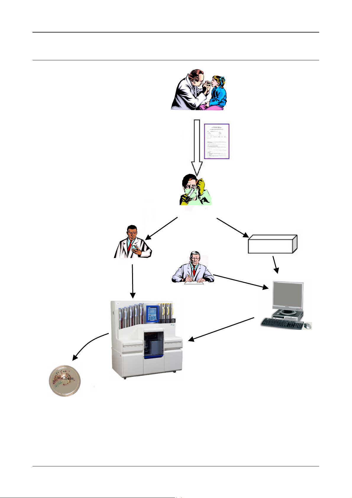
Description
Sample
Sample
Workflow Principle
Workflow Principle
Specimen collection
Incubation
User
Specimen reception &
sample preparation
Laboratory Manager
Sample data
Sample data
LIS
Sample data
Configuration
Figure 2-1 : Workflow Principle
2-2 PREVI
TM
Isola User Manual
Page 27
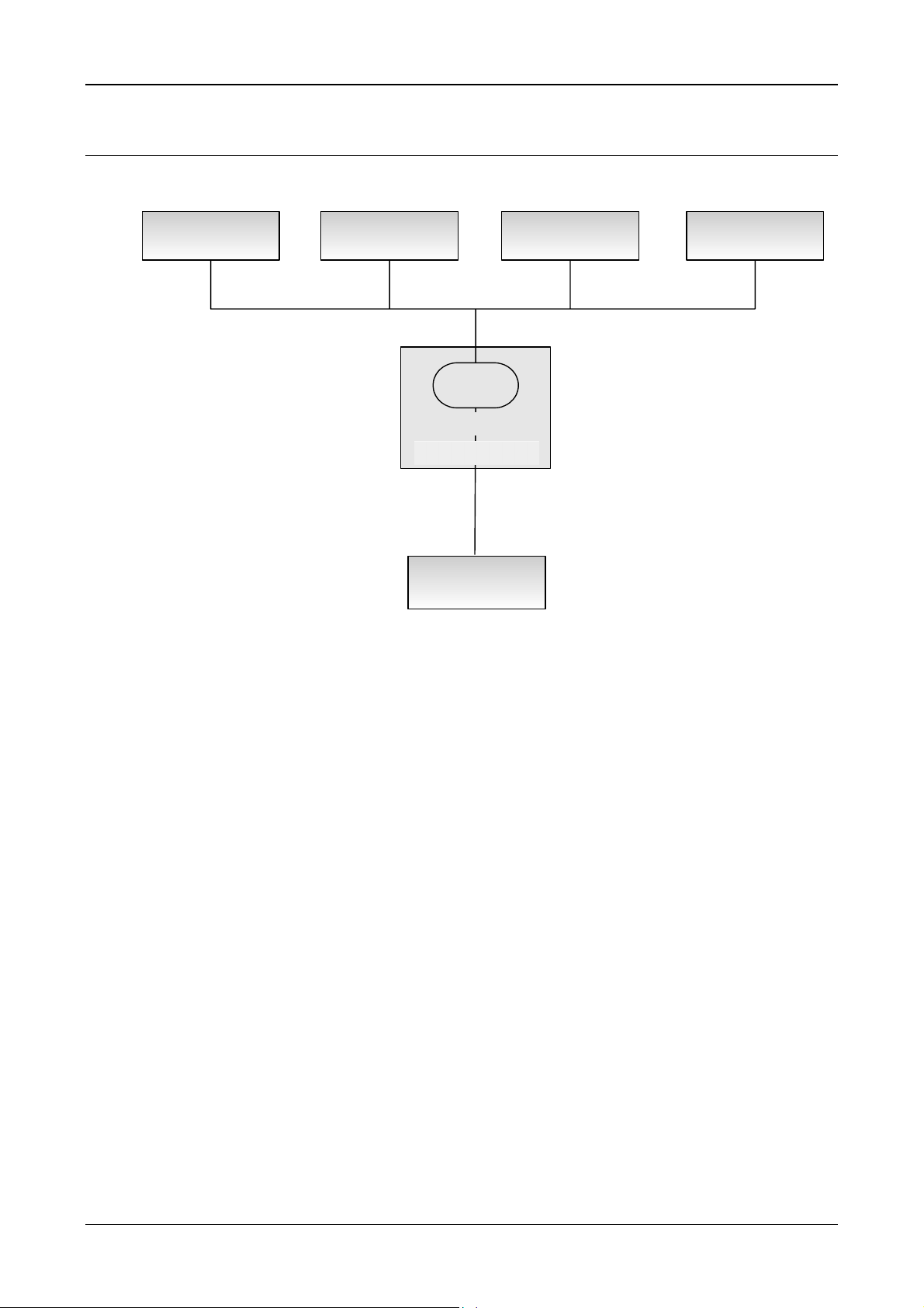
System Architecture
Description
System Architecture
PREVI Isola
Instrument 1
PREVI Isola
Instrument 2
PREVI Isola
Instrument 3
Data Server
WORKSTATION
BCI
LIS
PREVI Isola
Instrument 4
Figure 2-2 : System Architecture
LIS
Laboratory Information System.
BCI
Workstation
Bi-directional Computer Interface, a bridge to LIS.
User interface application which runs on a PC that is separate
from the instrument.
Data Server
The database holding amongst other things, the plate panel
definitions, and the sample assignments.
PREVI Isola
The plate processing instrument.
Note: Four PREVI Isola instruments can be connected to a workstation.
PREVI
TM
Isola User Manual 2-3
Page 28
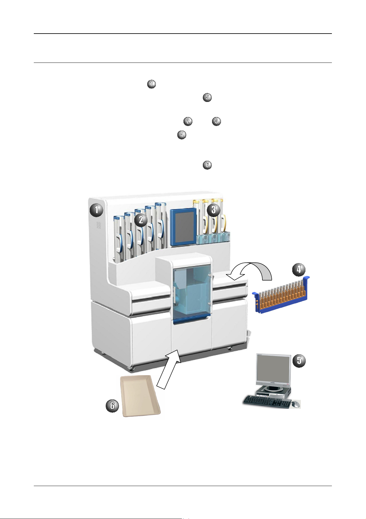
Description
System Components
System Components
The main system components are:
− an instrument
− a standalone computer - workstation
with an internal computer and a touch-screen
− a UPS (optional)
− two types of cassettes (input
− five types of sample racks
, output )
− consumables (PREVI Isola Applicators, PREVI Isola Tips, PREVI Isola Labels,
PREVI Isola Waste Bins)
− a waste paper bin (for label backing)
Figure 2-3 : System Components
2-4 PREVI
TM
Isola User Manual
Page 29

Workstation
Description
Note: Since the PREVI Isola system operates on a Microsoft Windows OS, it can be connected to
Description
Workstation
The workstation is composed of:
− 1 computer
− 1 screen
− 1 keyboard
− 1 mouse
− 1 barcode reader
− 1 printer (optional)
an external printer compatible with Microsoft Windows.
To validate this printer, please perform the Printer Verification Protocol, page 6-14.
PREVI
TM
Isola User Manual 2-5
Page 30
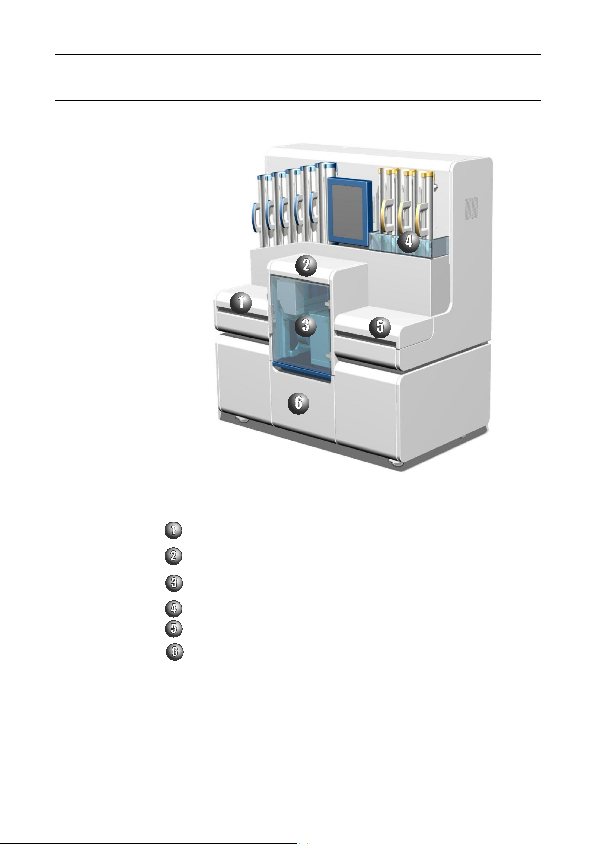
Description
Instrument
Instrument
Figure 2-4 : Front view of the PREVI Isola with covers on
Consumable lid
Provides access to the consumables tray for loading/unloading of tips and applicators.
Process station lid (nose cone and center cover).
Provides access to the processing area for wiping down the process stations.
Printer access door
Provides access for loading labels into the printer.
Output cassette guard
Sample lid
Provides access to the sample loading bay for loading/unloading of sample racks.
Waste drawer
CAUTION! The PREVI Isola contains moving mechanisms. Do not remove the process station lid
while the instrument is in operation.
2-6 PREVI
TM
Isola User Manual
Page 31

Description
Instrument
Figure 2-5 : Front view of the PREVI Isola – front covers removed
Input cassette
Output cassette
LCD touch-screen and graphic user interface
Consumables tray
Plate process station
Sample loading bay with rack tray
Waste drawer
Label printer
PREVI
TM
Isola User Manual 2-7
Page 32

Description
Instrument
Figure 2-6 : Back view of the PREVI Isola with covers on
Power connection socket
A standard socket for power connection is located on the lower right-hand side of the
rear panel for connecting to main power. The power connection socket contains two
fuses.
Power ON switch
The Power ON switch is located on the left-hand side of the PREVI Isola.
Rating plate
The rating plate details essential regulatory information.
Serial number
This number is unique to each instrument and should be quoted when requesting
technical support.
PREVI Isola HEPA filter location
Wall bumpers
The two wall bumpers fitted to the rear of the instrument provide minimum safe spacing
from the wall.
USB Ports
2-8 PREVI
TM
Isola User Manual
Page 33

Sample racks
Description
Instrument
Test samples are loaded in racks designed to accept one of eight types of tubes, when the
sample tray presents to the front right-hand side of the PREVI Isola.
Each type of rack has an associated aspiration height.
PREVI Isola Rack 1 PREVI Isola Rack 2
PREVI Isola Rack 4 PREVI Isola Rack 5
PREVI
PREVI Isola Rack 6 (Swab)
Figure 2-7 : Sample racks
TM
Isola User Manual 2-9
Page 34

Description
Instrument
Sample tubes
Tubes compatible for use with the PREVI Isola
Tube Description Supplier’s
Sterilin (Barloworld) 2mL Tube NA2 1 2 48.5 1900 18
Greiner VITEK® 2 tube (same
dimensions as Sarstedt
Haemolysis Tube)
ESwab 480CE 6 1 80 1000 69
Sarstedt Monovette Tube*
Sarstedt 10 mL tube 62.9924.283 2 10
Becton Dickinson Vacutainer 364948 2 10
Starplex Urine Container B902.10 4 90
Sarstedt Pot TP 30-001 or
Part Number
69285 1 6 74.6 1900 48.9 2900 35.6
10.252 &
10.253
TP 30-004
Rack
Name
Volume
(ml)
2 10 102 6000 50 9000 24 15
5 40 69.2 18000 41 37000 10 29.8
Total
Height
(mm)
100 5500 50 9000 21 16
100 6500 45 10000 20 16
76 33000 50 70000 22 43
Min
Volume
µL
Min
Height
mm
Max
Volume
µL
2500 5 11.5
4000 40 13
Max
Height
mm
* IMPORTANT! With Sarstedt Monovette tubes, if the sample volume is small, the plunger should not
be pushed up over the 6 ml mark otherwise the pipettor will collide with the plunger.
Fill heights
The Maximum Fill Height (measured from the top of the tube) is defined so as not to pollute
the pipettor body.
The Minimum Fill Height (measured from the top of the tube) is defined to enable the pipettor
to aspirate 95
µL.
IMPORTANT! Tubes must never be filled above the maximum fill height as this would affect pipettor
performance.
Diameter
(mm)
12.8
Figure 2-8 : Fill heights
Prepoured media (Plates)
Plates compatible for use with the PREVI Isola
The instrument supports round plates and bi-plates with a 90 – 94 mm outer diameter and a
total plate height of between 13.6 mm and 16 mm.
For plates with a nesting feature, please contact bioMérieux S.A. or your local bioMérieux
representative.
2-10 PREVI
TM
Isola User Manual
Page 35

Input cassettes
Description
Instrument
The PREVI Isola is equipped with five input cassettes. Input cassettes are blue.
Plates are loaded into the input cassettes agar-side up.
Each cassette is designed to hold up to 30 plates and the plates are loaded into the cassettes
according to the agar type. The agar type is displayed on the PREVI Isola touch-screen as
are the details of incubation requirements for completed plates.
Figure 2-9 : Input cassette – front Figure 2-10 : Input cassette – back
Handle
Cassette lock
Plate retention pin
Input cassette base
Plate level sensor window
IMPORTANT! Input cassettes will only fit in the input-side positions and output cassettes will only fit
in output-side positions.
PREVI
TM
Isola User Manual 2-11
Page 36

Description
Instrument
Output cassettes
The PREVI Isola is equipped with three output cassettes. Output cassettes are yellow.
On completion of processing, plates are stored, agar-side up, according to the incubation
type, in the output cassettes.
Each output cassette is designed to hold up to 30 plates.
Figure 2-11 : Output cassette - front Figure 2-12 : Output cassette - back
Handle
Cassette lock
Output cassette base
Plate level sensor window
IMPORTANT! Input cassettes will only fit in the input-side positions and output cassettes will only fit
in output-side positions.
Touch-screen
The PREVI Isola touch-screen is used to operate the instrument and inform the user of the
progress of streaking and the availability of consumables.
Figure 2-13: Touch-screen
2-12 PREVI
TM
Isola User Manual
Page 37

PREVI Isola Waste Paper Bin
The PREVI Isola includes a waste paper bin for the label backing.
Waste drawer
Description
Instrument
Figure 2-14 : PREVI Isola Waste Paper Bin
The waste drawer provides access to the PREVI Isola Waste Bins.
The instrument includes two different types of waste bins:
− one for biohazardous waste (PREVI Isola Tips and PREVI Isola Applicators),
− one for waste paper (label backing).
Waste applicators and tips are disposed of down a waste chute which ensures that the
biocontaminated tips and applicators are disposed of properly.
PREVI
Figure 2-15 : Waste Drawer
TM
Isola User Manual 2-13
Page 38

Description
Interlocks
Interlocks
The following PREVI Isola covers are equipped with interlocks for safety reasons:
− Consumable lid
− Process station lid
− Sample lid
− Output cassettes guard
− Printer access door
− HEPA filter latch
The process station lid should not be opened during operation.
The output cassette guard stops the instrument if it is opened during operation.
If the sample lid and consumable lid are opened during processing, a warning is generated
but the instrument is not stopped.
CAUTION! Do not bypass interlock systems for any reason. Interlock systems are a safety feature
designed to protect the user from injury and the instrument from damage.
The waste drawer is not equipped with an interlock. Nevertheless, it should not be
opened during processing.
2-14 PREVI
TM
Isola User Manual
Page 39

Consumables
PREVI Isola Applicators
PREVI Isola Applicators are single use microbiological sample applicators designed to streak
agar plates
Note: PREVI Isola Applicators are designed for single use. The PREVI Isola automatically discards
used applicators to the PREVI Isola biohazardous Waste Bin. Discarded applicators may be
biohazardous.
Description
Consumables
Figure 2-16 : PREVI Isola Applicator
PREVI Isola Applicator cartridge
PREVI Isola Applicator cartridge
PREVI Isola Applicator cartridges are pre-loaded with 120 PREVI Isola Applicators. They are
designed for single-use.
supplier
bioMérieux
Part Number
29509
PREVI
Figure 2-17 : PREVI Isola Applicator cartridge
TM
Isola User Manual 2-15
Page 40

Description
Consumables
PREVI Isola Tips
PREVI Isola Tips supplier Part Number
bioMérieux
29508
The PREVI Isola
Tips are designed for single use (1 tip = 1 sample).
Figure 2-18 : PREVI Isola Tips in tray
Note: PREVI Isola Tips are designed for single use. The PREVI Isola automatically discards used
tips to the PREVI Isola biohazardous Waste Bin. Discarded tips may be biohazardous.
IMPORTANT! The PREVI Isola must be used with PREVI
PREVI Isola Labels
A barcode label (30mm x 25mm), machine and human readable, is applied to the base of
each plate after completion of processing and prior to re-inversion of the base and reapplication of the lid.
IMPORTANT! The PREVI Isola must be used with PREVI Isola Labels only.
PREVI Isola Labels supplier Part Number
bioMérieux
PREVI Isola biohazardous Waste Bin
bioMérieux recommends the use of the following type of bin for biohazardous waste:
PREVI Isola biohazardous Waste Bin
supplier
bioMérieux 29718
Isola Tips only.
29720
Part Number
2-16 PREVI
TM
Isola User Manual
Page 41

PREVI Isola HEPA filter
The High Efficiency Particulate Air (HEPA) filter removes airborne particles from within the
PREVI Isola.
Description
Consumables
PREVI Isola HEPA filter supplier Part Number
bioMérieux 29711
PREVI
TM
Isola User Manual 2-17
Page 42

Description
Instrument Operating Principle
Instrument Operating Principle
Start Sample
Workflow
Index Next Sample
Read Sample Barcode
Start Plate
Workflow
Retrieve Input Plate
Transfer to Plate
Transfer Robot
Barcode?
Retrieve Sample Data
Sample data?
Pick up Tip
Aspirate Sample
Perform Plate Workflows
Wait for Plate Workflow
Completion
[Yes]
[Yes]
[No]
[No]
Transfer to
Process Station
Measure Agar Height
Height Check OK?
Dispense Sample
Pick up Applicator
Streak Plate
Discard Applicator
Bi-Plate?
[No]
[Yes]
[No]
Bad Plate
[Yes]
2nd Dispense Sample
2nd Pick up
Applicator
2nd Streak Plate
2nd Discard
Applicator
Dispose Tip
Transfer to Plate
Transfer Robot
End of Sample
Workflow
Label Plate
Transfer to
Output Robot
End of Plate
Workflow
Figure 2-19 : Simplified sample workflow
2-18 PREVI
TM
Isola User Manual
Page 43

Index next sample
Read sample barcode
Description
Instrument Operating Principle
The instrument indexes the next sample in the sample tray.
The sample tube is presented before an internal barcode reader in order to read the tube
barcode and identify the sample.
The internal barcode reader can read the following barcode formats:
− UPC
− EAN
− JAN
− Code 128
− Code 39
− ITF
− Codabar
− Code 93
The quality of the barcode label can affect the scanning performance. Poor quality labels are
more difficult to decode and may result in non-reads or potential misreads. The barcode label
should be printed to specifications. This means that the bars are printed within spec, with the
correct widths, no ink spread, crisp edges and no voids. There should be sufficient quiet zone
(white space) on both ends of the barcode label. For best results, the paper or label stock
should have matte finish to diffuse light. The print contrast signal (which is a comparison of
the reflectance of the bars and the background stock) should be as high as practical.
The instrument is configured to work best with barcodes where the line width is between
7.5 and 10 mil. This is determined by the distance from the barcode scanner to the barcodes.
Each barcode label should be affixed vertically on an upright tube with a maximum alignment
of +/- 4° in relation to the vertical axis of the tube.
The position of the label on the upright tube does not affect the reading. Preferably affix the
label in the middle of the tube as indicated below.
PREVI
Figure 2-20 : Positioning a barcode label on a tube
A = Maximum label size which depends on the tube (see the following table).
B = Maximum barcode symbols size which depends on the tube (see the following table).
TM
Isola User Manual 2-19
Page 44

Description
Instrument Operating Principle
Sterelin 2mL 1 48.5 24 19.5 17.5
Greiner VITEK® 2 1 74.6 49 45.6 43.6
ESwab 6 (Swab) 80 55 51 49
Tubes Rack
name
Tube Height
(mm)
A[mm] B[mm] for
(7.5mil)
B[mm] for
(10mil)
Retrieve sample data
Pick up tip
Sarstedt Monovette
2 102 77 73 71
Tube (10mL)
Sarstedt Tube (10mL) 2 100 75 71 69
BD Vacutainer (10mL) 2 100 75 71 69
Starplex Urine
4 76 51 47 45
Container (90mL)
Sarstedt Pot (40mL) 5 69.2 44 40.2 38.2
After reading the tube barcode, the instrument software requests the Data Server for sample
Information in order to process the sample.
If the sample is identified, the Data Server returns the streaking parameters for this sample
(i.e. plate panel and streaking protocol).
If the sample is not identified, it is skipped by the instrument and the instrument indexes the
next sample.
The electronic pipettor is mounted on the pipettor robot. The pipettor robot picks up the tip to
be used for sample aspiration.
Aspirate sample
Sample aspiration is performed by the electronic pipettor.
The pipettor using the tip, aspirates samples from pre-defined depths within sample tubes.
Before aspiration, the camera detects the presence of a tip. Should the camera report the
absence of a disposable tip, the pipettor continues to return to the tip tray until a disposable
tip is retrieved.
After aspiration, the camera detects the sample presence.
After aspiration the workflow continues with the processing of the plates for the sample.
2-20 PREVI
TM
Isola User Manual
Page 45

Perform plate workflow
Retrieve input plate
The plate input robot (left-hand side) retrieves agar plates from the input cassettes for delivery
to the plate transfer robot.
Transfer to plate transfer robot
The plate transfer robot accepts agar plates retrieved from the input cassette by the plate
input robot.
Transfer to process station
The plate transfer robot removes the lids by suction, maintains lid orientation, inverts the base
of the plates and delivers them to the process station for inoculation and streaking.
The plate process station holds the agar plates in position for ultrasonic detection of agar
height and plate orientation (whole or half-plate presence) before inoculation and streaking
can occur.
Measure agar height, dispense sample
An ultrasonic measurement device reports the distance between the tip and the agar plate
and the pipettor then delivers the aspirated sample to the agar plate and disposes the tip to
waste. The aspirated samples are delivered to the agar surface from an internally predefined
height. The total volume dispensed is no more than 95 µL and the number of plates streaked
with a single sample depends on the volume per plate which can be 10 µL or 20 µL.
Description
Instrument Operating Principle
Pick up applicator
Applicators are retrieved from the applicator cartridge by the applicator robot and positioned
over an inoculated agar plate for streaking. An applicator presence sensor reports applicator
presence.
Should the presence sensor report the absence of an applicator, the applicator robot
continues to return to the applicator cartridge until a disposable applicator is retrieved.
The applicator is picked up at the same time as the agar height is measured and the sample
dispensed.
Streak plate
The plate process station rotates to a maximum of 330° during the streaking process. Halfplate rotation is to a maximum of 110°.
Discard applicator
After plate streaking the applicator is discarded to waste.
If Bi – plate
If the processed plate is a bi-plate, the sample is dispensed a second time on the other half of
the plate.
The applicator robot picks up another applicator and the plate is streaked on the second half.
When streaking is complete the applicator is discarded.
Transfer to transfer robot
On completion of inoculation and streaking, the plate transfer robot accepts the processed
plate bases from the process station for barcode labeling, re-inversion of the bases and return
of the lids.
The plates are then delivered to the plate output robot for stacking into the output cassettes
agar side up.
PREVI
TM
Isola User Manual 2-21
Page 46

Description
Instrument Operating Principle
Label plate
Plate barcode labeling is carried out by the barcode printer installed in the PREVI Isola below
the plate transfer robot.
A barcode label is applied to the base of each plate after completion of processing and prior
to re-inversion of the base and re-application of the lid.
Transfer to output robot
The plate output robot (right-hand side) transports processed plates from the plate transfer
robot to the output cassettes.
Dispose of tip
On completion of the plate panel for a sample, the tip is disposed of by the pipettor robot into
the biohazardous waste bin.
2-22 PREVI
TM
Isola User Manual
Page 47

Workstation Software
Principle
The PREVI Isola needs to know what types of plates are to be streaked and what type of
incubation atmosphere they require. This is defined by plate panels which are assigned to
specimen types (see Assigning Plate Panels to Specimen Types, page 3-15) or samples (see
Assigning Plate Panels to Samples, page 3-22).
If a plate panel has been assigned to a specimen type, it will automatically be assigned to all
the samples of this specimen type when they are received from the LIS through BCI (see
Automatically Assigning Plate Panels to Samples, page 3-18). However, this assignment can
also be changed manually for individual samples (see Assigning Plate Panels to Samples,
page 3-22).
The PREVI Isola also needs to know in which input cassette each plate type is available and
which output cassette is assigned to each incubation type. This is defined by plate cassettes
configurations (see Defining Plate Cassettes Configurations, page 3-19 and Selecting Plates,
page 4-5).
The workstation software is an application running on the laboratory computer used to assign
test panels to samples for processing by the PREVI Isola and to monitor sample processing
status logs.
Description
Workstation Software
General screen layout
All the screens of the workstation software have the same general layout:
Figure 2-21 : General screen layout
PREVI
Each screen is composed of four parts:
Menu bar
Title and button bar
Working area
Status bar
TM
Isola User Manual 2-23
Page 48

Description
Workstation Software
Menu bar
Title and button bar
The menu bar includes three menus with submenus:
Samples Configuration Help
− Assign Samples − Plate Panels − About
− Show Worklist − Specimen Types
− Plate Cassettes Configuration
− General Settings
The title and button bar displays the title of the submenu selected from the menu bar.
It also contains buttons to perform actions.
Button
Working area
Status bar
Name
Add a row Delete New Print Save Validate Undo
Table 2-1 : Workstation software buttons
The working area is different for each screen.
The status bar displays the user’s login and a button for quitting or changing users.
2-24 PREVI
TM
Isola User Manual
Page 49

Instrument Software
The instrument software allows the user to operate the instrument through a graphical
interface.
Main screen and general layout
All the screens of the instrument software have the same general layout.
Description
Instrument Software
PREVI
Figure 2-22 : Main screen layout
Each screen is composed of five parts:
Alarm zone
Title bar
Navigation/action bar
Working area
Status bar
TM
Isola User Manual 2-25
Page 50

Description
Instrument Software
Alarm zone
The alarm zone comprises four buttons, which correspond to four alarm types: Instrument,
Connection, Consumables, Samples.
Alarm Type OK Warning Error
Instrument
Connection
(Instrument-Workstation)
Consumables
Title bar
Samples
Table 2-2 : Alarm types
When there is a warning or an error, the alarm button blinks.
When it blinks, the user should touch it to display the “Event Log” screen (see Event Log,
page 9-10). The button will stop blinking.
The title bar contains either the status of the instrument (when the main screen is displayed):
− Ready
− Processing
− Pausing
− Paused
− Error
− etc.
or the purpose of the screen (when another screen is displayed).
Status bar
The two most recently generated messages are displayed in the status bar, along with the
current time and date, and the instrument name (PREVI Isola).
2-26 PREVI
TM
Isola User Manual
Page 51

Navigation/action bar
The buttons in the navigation/action bar are used either to navigate to different screens, or to
perform actions, or both.
The appearance of the buttons varies according to their status.
When a button is pressed, it becomes yellow. When it is disabled, it is greyed out.
Description
Instrument Software
Disabled
Pressed Enabled
The navigation buttons (except the Home button) are toggle buttons: when the user touches a
navigation button to switch to a different screen (for example: the Samples Screen), the
button remains pressed (it stays yellow), and if the user touches that button again, the
software navigates back to the main screen.
Button Name Action
Home Navigates to the main screen.
Samples Navigates to the “Samples” screen and presents the sample tray for
loading/unloading (see Loading Sample Racks, page 4-21).
Plates Navigates to the “Plates” screen (see Selecting Plates, page 4-5).
Applicators & Tips Navigates to the “Applicators and Tips” screen and presents the
consumable tray for loading of applicators and tips (see Loading
PREVI Isola Applicators, page 4-10).
Label Roll Navigates to the “Load Labels” screen and moves the plate transfer
robot out of the way of the printer so that the user has clear access
to the printer (see Loading PREVI Isola Labels, page 4-15).
PREVI
Empty Waste Bin Only enabled when the main screen is displayed.
Start/Resume
Processing
The user touches this button to signal the instrument software that
the waste bin has been emptied (see Removing Waste, page 4-35).
Only enabled when the main screen is displayed.
It starts processing, or resumes processing after pause (see
Processing Samples, page 4-23).
Pause Processing Pauses processing after completing the current samples (see
Pausing the Instrument, page 4-28).
Stop Processing Stops processing (see User-generated stop, page 4-31).
Maintenance Navigates to the “Maintenance” screen (see Presentation of the
Maintenance Menu, page 8-2).
Immediate
stop/Shut down
Stops the instrument immediately and allows the user to choose
whether to reinitialize it or shut it down (see Powering Down the
Instrument, page 4-37).
Table 2-3 : Navigation/action bar buttons
TM
Isola User Manual 2-27
Page 52

Description
Instrument Software
Working area
The working area is different for each screen.
The working area of the main screen is composed of three parts.
Figure 2-23 : Working area
Sample processing status
Plate cassette status
Consumables status
2-28 PREVI
TM
Isola User Manual
Page 53

3 Getting Started
Assembly and Installation
DANGER! The PREVI Isola must be installed by bioMérieux S.A. Technical Assistance or your
local bioMérieux representative.
CAUTION! Before unpacking the various PREVI Isola components, it is advisable to have
previously planned where they will be placed.
Choosing a location
WARNING! Avoid exposing the PREVI Isola to direct sunlight, excessive heat, humidity or dust.
Leave sufficient space around the PREVI Isola (minimum 50 cm on each side and at the
rear of the instrument) to allow airflow and easy handling of the instrument. The rear of
the instrument is equipped with wall bumpers to
Do not obstruct the hardware ventilation apertures.
prevent impacts with the wall.
Electrical connections
CAUTION! Nothing should be placed on top of connection cables, whether temporarily,
permanently or intermittently. Cables should not be laid across passage-ways.
Computer cables must not intersect or be placed close to power supply cables. Cables
should not be looped or knotted, or be rolled up near or on other electrical equipment.
Hazardous Magnetic Fields Precautions
WARNING! This product contains very strong permanent magnet arrays.
Extreme care should be taken when handling tools and other magnetic material in
close proximity to the magnet arrays, as sudden high mechanical forces may be
generated.
Magnetically sensitive items such as computer discs and tapes, audio and video
cassettes, and credit cards should be kept well clear of the magnet arrays, as these
items may be damaged by strong magnetic fields.
People wearing a pacemaker should not use this product, as the strong magnetic fields
associated with this product may adversely affect or damage the pacemaker.
Moving the Instrument
WARNING! The instrument should be moved by personnel who are authorized to do so by
bioMérieux S.A.
Barcode Reader Installation
Sample barcodes can be entered manually or scanned using the hand-held barcode reader
that is connected to the workstation.
For installation of the barcode reader, please refer to the installation procedure included in
PREVI
TM
Isola User Manual 3-1
the barcode reader package.
Page 54

Getting Started
Installation of the PREVI Isola and BCI
Installation of the PREVI Isola and BCI
Installation of the PREVI Isola and BCI software is performed by bioMérieux or your local
bioMérieux representative.
Users are trained during installation of the PREVI Isola so that they are able to derive the
best performance from the instrument.
WARNING! The different equipment, software, and configuration software (especially date, time,
language, keyboard type, and other formats) composing the PREVI Isola have been
validated by bioMérieux
additions to a configuration that do not correspond to one of the validated subunits
can lead to malfunctions.
Checking installation
After the PREVI Isola has been installed, bioMérieux S.A. Technical Assistance or your local
bioMérieux representative will perform a test to check that the system is operating correctly.
WARNING! If the equipment is used in a manner not specified in the instructions for use provided
by bioMérieux, the protection provided by the equipment may be impaired.
S.A. to function together as an integrated unit. Any changes or
3-2 PREVI
TM
Isola User Manual
Page 55

Getting Started
Powering up the Workstation
Powering up the Workstation
IMPORTANT! The workstation must be running when the instrument is in use and when the LIS
sends information to the PREVI Isola.
• Power up the workstation.
Initialization begins.
The Windows software opens:
The Windows loading screen is displayed,
• Enter your login and password.
The Windows session opens.
Connecting to BCI NET
For further information on how to use BCI NET, refer to the BCI NET User’s Manual.
IMPORTANT! BCI NET must be running when the instrument is in use and when the LIS sends
information to the PREVI Isola.
Connecting to BCI RS232
For further information on how to use BCI RS232, refer to the BCI RS232 User’s Manual.
PREVI
TM
Isola User Manual 3-3
Page 56

Getting Started
Starting the Workstation Software
Starting the Workstation Software
• Open a Windows session.
• Start the workstation software by double-clicking on the application icon .
The login pop-up window is displayed.
Figure 3-1 : Login pop-up window
• Enter the user name and password which is the same as for Windows.
• Click “OK”.
The user is logged on and has access to the functions that are available to his/her group.
Entry of an incorrect user name or password
If an incorrect user name or password has been entered or if a user account has been locked,
the following window is displayed:
Figure 3-2 : “Invalid user name / password” window
• Click “OK” to close the window.
• Enter a new user name and password to start the application.
IMPORTANT! After three unsuccessful attempts to enter the password, the user will not be able to
start the application as the account will have locked. It can only be unlocked by a user
with Administrator or Power User privileges.
3-4 PREVI
TM
Isola User Manual
Page 57

Changing work sessions
Each user has a login and personal password which are required to open a work session on
the workstation software.
If another person needs to use the instrument, they will have to open a work session on the
workstation software using the login:
• Click in the status bar.
• Click “Logout” .
Getting Started
Starting the Workstation Software
The workstation software shutdown window is displayed:
Figure 3-3 : Workstation software shutdown window
The new login window is displayed.
Inactivity timeout
If the workstation software remains inactive for more than 15 minutes, it automatically logs
out.
Any changes which have not been saved beforehand will be lost.
PREVI
TM
Isola User Manual 3-5
Page 58

Getting Started
Defining Plate Panels
Defining Plate Panels
The PREVI Isola needs to know what types of plates are to be streaked. This is defined by
plate panels which are assigned to specimen types or samples.
The following screen is used to create Plate Types, Incubation Types and Plate Panels.
In the “Configuration” menu,
• Select “Plate Panels” to display the “Plate Panels” screen.
Figure 3-4 : “Plate Panels” screen
The “Plate Panels” navigation tree displays the list of all existing plate panels, sorted
alphabetically.
By default, the first plate panel (if any) is selected and its composition is displayed in the table
in the upper part of the screen.
The table in the lower part of the screen contains two tabs for creating plate types and
incubation types.
3-6 PREVI
TM
Isola User Manual
Page 59

Creating a plate panel
• Click on the button.
Getting Started
Defining Plate Panels
The plate panel composition part of the screen is refreshed. The field name and the
composition table are empty.
Figure 3-5 : Create a plate panel
• Enter the name of the desired plate panel.
The plate panel name must be unique and include up to 50 characters.
Note: It is recommended to enter names that will remind you of the types of specimens for which
this plate panel will be used.
A plate panel can only include 5 plate types.
• Fill the plate panel composition table.
To do this,
• Click on the button (1).
A row is added to the composition table.
The maximum number of rows accepted in the plate panel composition table is 5.
PREVI
TM
Isola User Manual 3-7
Page 60

Getting Started
Defining Plate Panels
Note: A plate type or incubation type can be selected using either the full name or the abbreviated
If more than the maximum number of rows is created, an error message is displayed.
Figure 3-6 : “Plate Panel” error message
• Select a plate type and an incubation type from the drop-down lists.
name.
If the lists do not contain the plate types and incubation types required, they can be created
using the tables in the lower part of the screen (see page 3-11).
• Click on the button to cancel,
or
• Click to save the new plate panel.
If a field is not adequately filled i.e. missing mandatory information, or invalid contents, an
error message is displayed and the invalid field is flagged ( ). Place the pointer on the
icon to obtain more information about the error.
!
!
Figure 3-7 : “Invalid entry” error message
• Proceed in the same manner until the plate panel is complete.
3-8 PREVI
TM
Isola User Manual
Page 61

Getting Started
Defining Plate Panels
Modifying a plate panel
IMPORTANT! Only plate panels that are not in use (i.e. not assigned to any specimen types or
samples, or only to samples no longer in the database) can be modified.
• In the “Configuration” menu, select “Plate Panels” to display the “Plate Panels” screen.
• Click on a plate panel in the navigation tree.
The selected plate panel is displayed in the plate panel composition part of the screen.
• Modify the name and/or the composition of the plate panel: you can add rows by clicking
on
You can also select a different plate type or incubation type for an existing row.
Note: If you try to modify a plate panel that is in use, an error message is displayed: “This plate
panel cannot be modified as it is in use” and the change is cancelled.
and delete rows by clicking on .
• Click on the button to cancel,
or
• Click on the button to save the modified plate panel.
The plate panel screen is refreshed and the name of the modified plate panel is updated
in the navigation tree.
Deleting a plate panel
IMPORTANT! Only plate panels that are not in use (i.e. not assigned to any specimen types or
samples, or only to samples no longer in the database) can be deleted.
• In the “Configuration” menu, select “Plate Panels” to display the “Plate Panels” screen.
• Click on a plate panel in the navigation tree.
The selected Plate Panel is displayed in the plate panel composition part of the screen.
PREVI
• Click on the button in the title and button bar to delete the plate panel.
A confirmation message is displayed:
Figure 3-8 : “Delete a plate panel” confirmation message
• Click “OK” to confirm deletion of the plate panel.
The “Plate Panel” screen is refreshed.
The deleted plate panel is removed from the navigation tree, the first plate panel (if any)
is selected and its composition is displayed in the upper part of the screen.
TM
Isola User Manual 3-9
Page 62

Getting Started
Defining Plate Panels
Printing a plate panel
To print plate panels,
• Click on the button.
The selected plate panels or all the plate panels depending on the choice, are displayed in a
“Print Preview” window.
A plate panel printing selection window is displayed:
Figure 3-9 : “Plate Panel Printing” selection window
Figure 3-10 : Plate panel “Print Preview” window
• Click on the “Print” button in the “Print Preview” window.
A printing dialog box is displayed.
• Select a printer and click “OK”.
The report is printed.
• Close the “Print Preview” window.
3-10 PREVI
TM
Isola User Manual
Page 63

Defining Plate Types
Getting Started
Defining Plate Types
Creating a plate type
Note: If possible, to reduce the risk of errors, it is recommended to use the code that is printed on
Figure 3-11 : “Plate Panels” plate types screen
In the “Configuration” menu,
• Select “Plate Panels” to display the “Plate Panels” screen.
• Click on the “Plate Types” tab.
In the “Plate Types” tab,
• Click on the button (1).
A row is added to the end of the plate type table.
• Enter the abbreviated plate type name.
The abbreviated plate type name must be unique and include up to 4 characters.
the plates.
• Enter the plate type composition.
The plate type composition must be unique and include up to 50 characters.
• Select the “Geometry” from the drop-down list.
PREVI
• Click on the button to cancel,
or
• Click to save the new plate panel.
TM
Isola User Manual 3-11
Page 64

Getting Started
Defining Plate Types
If a field is not adequately filled i.e. missing mandatory information, or invalid contents, an
error message is displayed and the invalid field is flagged ( ). Place the pointer on the
icon to obtain more information about the error.
• Proceed in the same manner until the plate panel is complete.
Modifying a plate type
To modify an abbreviated plate type name and composition,
• Click in the field to modify and then enter the new name.
Modification of the geometry name is not allowed.
!
!
Deleting a plate type
Only plate types which are not used by at least one plate panel or plate cassettes
configuration can be deleted.
• Select a plate type.
• Click on the button to delete the plate type.
The “Plate Panel” screen is refreshed. The deleted plate type is removed from the plate
type table and the next plate (if any) is selected.
3-12 PREVI
TM
Isola User Manual
Page 65

Defining Incubation Types
In the “Configuration” menu,
• Select “Plate Panels”.
In the “Plate Panels” screen,
• Click on the “Incubation Type” tab.
The “Incubation Types” table contains the list of all the existing incubation types.
Getting Started
Defining Incubation Types
Creating an incubation type
In the “Incubation Types” tab,
• Click on the button (1).
A row is added to the end of the incubation type table.
• Enter the abbreviated incubation type name.
The abbreviated incubation type name must be unique and include up to 4 characters.
Note: It is recommended to use names that remind you of the incubator in which the plates will be
loaded.
• Enter the full incubation type name.
The full incubation type name must be unique and include up to 50 characters.
Figure 3-12 : Define incubation types
PREVI
TM
Isola User Manual 3-13
Page 66

Getting Started
Defining Incubation Types
• Click on the button to cancel,
or
• Click on in the title and button bar to save the new incubation types.
Figure 3-13 : Incubation types
• Proceed in the same manner for all the incubation types to be created.
Modifying an incubation type
IMPORTANT! Only incubation types that are not used by at least one plate panel or plate cassettes
configuration can be modified.
• Select the incubation type to modify.
• Modify its abbreviated name and/or its full name.
• Click on the button to cancel,
or
• Click on the button to save the modified incubation type.
Deleting an incubation type
IMPORTANT! Only incubation types that are not used by at least one plate panel or plate cassettes
configuration can be deleted.
• Select an incubation type.
• Click on the button to delete the incubation type.
The incubation types table is refreshed. The deleted incubation type is removed from the
incubation types table and the next row (if any) is selected.
3-14 PREVI
TM
Isola User Manual
Page 67

Assigning Plate Panels to Specimen Types
Assigning Plate Panels to Specimen Types
The PREVI Isola needs to know what types of plates are to be streaked. This is defined by
plate panels which are assigned to specimen types or samples.
Due to the limitation of the maximum sample volume pipetted, certain streaking protocols are
not compatible with certain plate panels.
In the “Configuration” menu,
• Select “Specimen Types”.
The following screen is used to assign plate panels to specimen types.
Getting Started
Figure 3-14 : “Specimen Types” screen
If a plate panel has been assigned to a specimen type, it will automatically be assigned to all
the samples of that specimen type when they are received from the LIS. (see Automatically
Assigning Plate Panels to Samples, page 3-18).
To have different plate panels for the same specimen type depending on other data, e.g. age
of patient, result of another test, use the specimen details field.
A row must be created for each specimen type to process on the PREVI Isola (or several
rows if different plate panels are required according to the specimen details).
• Click on the button.
A row is added to the end of the specimen type table.
If a field is not adequately filled i.e. missing mandatory information, or invalid contents, an
error message is displayed and the invalid field is flagged ( ). Place the pointer on the
!
icon to obtain more information about the error.
!
• Enter the name and LIS code of the specimen type.
The specimen type name must be unique and include up to 40 characters and the LIS
code must be unique and include up to 10 characters.
• Select a streaking protocol from the drop-down list.
There is one streaking protocol per specimen group (urine, feces, swabs, blood, liquid
respiratory, enrichment broth, quality control).
PREVI
TM
Isola User Manual 3-15
Page 68

Getting Started
Assigning Plate Panels to Specimen Types
• Select a plate panel from the drop-down list (if the required plate panel is not found, it
must be created: see Creating a plate panel, page 3-7).
• The composition of the selected plate panel is displayed in the plate panel composition
table in the lower part of the screen.
• If specimen details are required, proceed in the same way, but fill the specimen details
field. The specimen details must be unique and include up to 40 characters and the LIS
code must be unique and include up to 10 characters.
To delete a specimen type and/or specimen details,
• Select the row to delete and click on the button.
Note: Only specimen types/specimen details which are not in use (i.e. not assigned to any samples
or only to samples no longer in the database) can be deleted.
When deleting a specimen type, all the specimen details associated with it must be deleted
beforehand.
The specimen types table is refreshed.
The deleted specimen type is removed from the specimen types table and the next row (if
any) is selected.
• Click on the button to cancel,
or
• Click on the button to save changes.
3-16 PREVI
TM
Isola User Manual
Page 69

Printing plate panels assigned to specimen types
To print plate panels assigned to specimen types,
• Click on the button.
The report is displayed in a “Print Preview” window.
Getting Started
Assigning Plate Panels to Specimen Types
Figure 3-15 : Specimen types “Print Preview” window
• Click on the “Print” button in the “Print Preview” window.
A printing dialog box is displayed.
• Select a printer and click “OK”.
The report is printed.
• Close the “Print Preview” window.
PREVI
TM
Isola User Manual 3-17
Page 70

Getting Started
Automatically Assigning Plate Panels to Samples
Automatically Assigning Plate Panels to Samples
The software will consult the specimen types table for each sample received from the LIS
(see Assigning Plate Panels to Specimen Types, page 3-15).
It will first take into account the specimen details to assign a plate panel to a sample.
If the specimen details have not been sent by the LIS, it will assign the plate panel defined for
the specimen type to the sample, if any.
If no row has been created in the specimen types table for specimen details, the plate panel
defined for the specimen type will be used, if any.
However, if a row has been created for specimen details with a “<not defined>” plate panel,
the plate panel of the specimen type will not be used. This ensures that certain specimen
details will not be taken into account by the PREVI Isola unless they are assigned plate
panels manually.
Examples:
1. In this case:
If the Specimen Details field is not filled in for the urine sample, it will not be processed.
2. In this case:
If the Specimen Details field is not filled in for the urine sample, it will be processed like a
positive urine.
3-18 PREVI
TM
Isola User Manual
Page 71

Defining Plate Cassettes Configurations
The PREVI Isola needs to know in which input cassette it can find each type of plate. This is
defined by plate cassettes configurations.
The plate cassette configurations are created using the workstation software and are then
selected on the instrument touch-screen.
IMPORTANT! If a plate type is used in several plate cassettes configurations, it is recommended if
possible, to always assign it to the same input cassette. This will reduce the number of
manipulations and the risk of error.
It is also recommended to assign incubation types to the same output cassettes to
reduce the risk of error.
In the “Configuration” menu,
• Select “Plate Cassettes”.
The “Plate Cassettes Configuration” screen is displayed.
Creating a plate cassettes configuration
Getting Started
Defining Plate Cassettes Configurations
• Click on the button.
The “Plate Cassettes Configuration” screen is refreshed. All the fields are empty.
PREVI
Figure 3-16 : “Plate Cassettes Configuration” screen
• Enter a name for the new plate cassettes configuration.
The plate cassettes configuration name must be unique and include up to 50 characters.
Note: It is recommended to use names that remind you of the types of specimens that can be
processed with this plate cassettes configuration.
TM
Isola User Manual 3-19
Page 72

Getting Started
Defining Plate Cassettes Configurations
• Select a plate type from the drop-down list for each input cassette.
• Select an incubation type from the drop-down list for each output cassette.
Note: A plate type or incubation type can be selected using either the full name or the abbreviated
name.
Figure 3-17 : New plate cassettes configuration
• Click to save the new plate cassettes configuration,
or
• Click on the button to cancel.
If a field is not adequately filled i.e. missing mandatory information, or invalid contents, an
error message is displayed and the invalid field is flagged ( ). Place the pointer on the
icon to obtain more information about the error.
!
!
Figure 3-18 : “Invalid Input” error message
3-20 PREVI
TM
Isola User Manual
Page 73

Modifying a plate cassettes configuration
• In the “Configuration” menu, select “Plate Cassettes” to display the “Plate Cassettes
Configuration” screen.
• Click on a plate cassettes configuration in the navigation tree.
The selected plate cassettes configuration name and composition are displayed.
• Modify the name and/or the composition of the plate cassettes configuration.
• Click on the button to cancel,
or
• Click on the button to save the modified plate cassettes configuration.
The plate cassettes configuration screen is refreshed and the name of the modified plate
cassettes configuration is updated in the navigation tree.
Getting Started
Defining Plate Cassettes Configurations
Deleting a plate cassettes configuration
• In the “Configuration” menu, select “Plate Cassettes” to display the “Plate Cassettes
Configuration” screen.
• Click on a plate cassettes configuration in the navigation tree.
The selected plate cassettes configuration name and composition are displayed.
• Click on the button in the title and button bar to delete the plate cassettes
configuration.
A confirmation message is displayed:
Figure 3-19 : “Delete a plate cassettes configuration” confirmation message
• Click “OK” to confirm deletion of the plate cassettes configuration.
The “Plate Cassettes Configuration” screen is refreshed.
The deleted plate cassettes configuration is removed from the navigation tree.
PREVI
TM
Isola User Manual 3-21
Page 74

Getting Started
Assigning Plate Panels to Samples
Assigning Plate Panels to Samples
Plate panels are normally automatically assigned to samples when the sample data are
received from the LIS (see Automatically Assigning Plate Panels to Samples, page 3-18).
This assignment is based on specimen types and details (see Assigning Plate Panels to
Specimen Types, page 3-15). However, this assignment can also be changed manually for
individual samples.
Manual assignment of plate panels to samples is also used for quality control.
In the “Samples” menu,
• Select “Assign Samples” to display the “Sample Assignment” screen.
The “Sample Assignment” screen is displayed.
Figure 3-20 : “Sample Assignment“ screen
• Select a streaking protocol and a plate panel using the drop-down lists at the top of the
screen.
• Scan the barcode on the sample tube.
• Alternatively, you can enter the barcode manually and click on the button or the
<Enter> key.
3-22 PREVI
TM
Isola User Manual
Page 75

Getting Started
Assigning Plate Panels to Samples
The samples will be added to the table.
Figure 3-21 : “Sample Assignment“ screen with sample
• Proceed in the same manner for each sample.
• Click on the button to cancel,
or
• Click on the button to save.
The samples disappear from the table and can be viewed in the worklist screen (see
Viewing and Printing Worklists, page 3-24).
Note: The drop-down lists include two special values: “default” and “not defined”. “Default” allows
you to cancel a manual assignment and revert to the default plate panel and streaking
protocol of the specimen type. ”Not defined” should only be used if you do not want the
instrument to process a sample.
IMPORTANT! If an incorrect streaking protocol or plate panel is assigned to a sample which is then
processed, the sample will have to be reprocessed. However, before it is reprocessed,
it must be given a new sample ID. The barcode on the sample tube must be modified to
include this new sample ID.
To process the same specimen ID with different sample IDs, contact bioMérieux.
PREVI
TM
Isola User Manual 3-23
Page 76

Getting Started
Viewing and Printing Worklists
Viewing and Printing Worklists
The “Worklist” screen is used to view a list of samples with their processing state, in particular
to check that all samples for which data have been received from the LIS have been
processed successfully.
In the “Samples” menu,
• Select “Show Worklist”.
The “Worklist” screen is displayed.
Figure 3-22 : “Worklist” screen
Data can be filtered according to the specimen collection date, specimen type, processing
state or sample ID.
• Select the criteria and then,
• Click .
Columns can be moved by dragging and dropping.
Rows can be sorted by clicking on the header of the corresponding column.
3-24 PREVI
TM
Isola User Manual
Page 77

Getting Started
Viewing and Printing Worklists
To print a worklist,
• Click on the button.
The report is displayed in a “Print Preview” window.
Figure 3-23 : Worklist “Print Preview” window
• Click on the “Print” button in the “Print Preview” window.
A printing dialog box is displayed.
• Select a printer and click “OK”.
• Close the “Print Preview” window.
PREVI
TM
Isola User Manual 3-25
Page 78

Getting Started
General Settings
General Settings
In the “Configuration” menu,
• Select “General Settings”.
The “General Settings” screen is displayed.
Figure 3-24 : “General Settings” screen
The following parameters can be defined in the “General Settings” screen:
Data retention period (days)
This defines the number of days that data are stored in the database after the most
recent modification.
Archive time of day
This defines the time at which archiving will be performed.
Archiving should be programmed to occur when the instrument is not in use and when
the antivirus full scan is not running.
Logout timeout (min)
This defines the period of inactivity (in minutes) after which the user will be logged off
from the application.
BCI Configuration
The BCI configuration is done by bioMérieux at installation and should not be modified
by the user.
3-26 PREVI
TM
Isola User Manual
Page 79

4 Using the System
Basic Workflow
Power Up
Check and Load Consumables
Applicators
Pipettor Tips
Labels
Waste Bins
Load Plates
Prepare Samples
Load Samples
Process Samples
Unload
Samples
Plates
Waste
Pause
PREVI
Power Down
Figure 4-1 : Basic workflow diagram
TM
Isola User Manual 4-1
Page 80

Using the System
Starting the System
Starting the System
IMPORTANT! The workstation must be running when the system is started (see Powering up the
Workstation, page 3-3).
The PREVI Isola system is started as follows:
− The UPS is powered up (optional device).
− The instrument is powered up.
− The internal computer starts up automatically.
− The instrument software starts.
− The system initializes.
Powering up the instrument
Before initialization,
− All the instrument covers must be closed.
− All the input and output cassettes must be in place on the instrument.
− The waste drawer must be closed.
CAUTION! Input and output cassettes must not be removed during initialization.
• Put the power switch on the instrument in the “I” position.
Figure 4-2 : Powering up the instrument
CAUTION! In case of emergency, switch off the power at the power switch.
Screensaver
If the instrument user interface is not used for a period of time, the screen will become black.
• Simply touch the screen and the main screen will appear.
4-2 PREVI
TM
Isola User Manual
Page 81

Using the System
Starting the System
After the computer completes initialization, the main screen (see Main screen and general
layout, page 2-25) appears:
PREVI
Figure 4-3 : Main screen
The instrument is now in “Ready” status.
TM
Isola User Manual 4-3
Page 82

Using the System
Prerequisites for Sample Processing
Prerequisites for Sample Processing
Samples must be in liquid form. Samples not in liquid form must be prepared as outlined in
Sample Preparation, on page 4-19.
Samples must be in compatible tubes (see Sample tubes, page 2-10). If a sample is not
received in a compatible tube it must be transferred.
Samples for processing must be barcoded in a format accepted by the instrument (see Read
sample barcode, page 2-19).
Pre-start Checks
• Check that the instrument is in “Ready” status.
• Make sure that there are sufficient consumables to process samples (see pages 4-5 to
4-15)
• Make sure that the PREVI Isola Waste Bins are in place and empty (see Removing
Waste, page 4-35).
• Select the appropriate plate cassettes configuration and load the corresponding plates
into the input cassettes (see Selecting Plates, page 4-5).
• Make sure that output cassettes are empty (see Unloading Processed Plates,
page 4-32).
IMPORTANT! Please refer to the package inserts for use of the plates and consumables.
4-4 PREVI
TM
Isola User Manual
Page 83

Selecting Plates
IMPORTANT! Please refer to the package inserts for use of the plates.
Note: For information on compatible plates, refer to Plates compatible for use with the PREVI Isola,
page 2-10.
The instrument status should be “Ready” before changing the plate cassettes configuration.
Before loading plates, it is necessary to select the plate cassettes configuration. To do this,
• Touch the button on the instrument touch-screen to display the “Select Plates”
screen:
Using the System
Selecting Plates
PREVI
Figure 4-4 : “Select Plates” screen
TM
Isola User Manual 4-5
Page 84

Using the System
Selecting Plates
The “Current Plate Cassettes Configuration” is displayed.
To select a different plate cassettes configuration,
• Scroll using the and buttons in the “New Plate Cassettes Configuration”
zone
.
• Touch the button to accept the “New Plate Cassettes Configuration”.
The new plate cassettes configuration will now be displayed in the “Current Plate Cassettes
Configuration” zone.
• Touch the button to return to the main screen.
4-6 PREVI
TM
Isola User Manual
Page 85

Loading Plates
To load plates,
• Remove the input cassette.
IMPORTANT! Make sure that the plates are not contaminated.
Plates must be loaded upside down (agar side up).
The user is responsible for ensuring that the appropriate plate types are loaded into the
correct input cassette.
Using the System
Loading Plates
Figure 4-5 : Load plates agar-side up
• Put the input cassette back in place on the instrument.
IMPORTANT! Make sure the input cassettes are properly installed otherwise the instrument will not
be able to start processing.
Before starting sample processing, ensure that the output cassettes are empty and
properly installed.
Loading plates during processing
During processing, the instrument monitors the plates remaining in the input cassettes. If the
instrument considers there are not enough plates to process the next sample, it will display an
alarm message and will pause.
• Remove the empty input cassette.
• Load plates and put the input cassette back in place.
To resume processing,
• Touch the button on the main screen.
PREVI
TM
Isola User Manual 4-7
Page 86

Using the System
Loading Plates
Loading plates without removing the input cassette
Plates can be loaded at any time without removing the input cassettes.
Figure 4-6 : Loading plates without removing the input cassette
DANGER! Do not put your hands into the lower part of the input cassette while the instrument
is operating.
4-8 PREVI
TM
Isola User Manual
Page 87

Plate cassettes status
The input and output cassettes status is displayed on the main screen.
The name of the selected plate cassettes configuration is displayed at the top.
For each input cassette, the abbreviated name of the assigned plate type is displayed.
For each output cassette, the abbreviated name of the assigned incubation type is displayed.
The cassettes status is refreshed in real-time during processing.
Using the System
Loading Plates
Figure 4-7 : Main screen – “Cassettes status”
An image shows the level of plates in each input or output cassette:
Unknown Empty Nearly full/empty Full
Table 4-1 : Plate cassettes status icons
When an input cassette is nearly empty, the remaining number of plates is displayed above
the image.
When an output cassette is nearly full, the instrument displays how many plates can still be
inserted.
When an input cassette is removed, the status of all the input cassettes becomes “Empty”.
When an output cassette is removed, the status of all the output cassettes becomes “Full”.
During processing, when the level of plates falls below the sensor, the PREVI Isola considers
that there are 5 plates remaining in the input cassette and starts counting down.
Note: If an error occurs, this 5-plate count is lost and the input cassette is considered to be empty.
PREVI
TM
Isola User Manual 4-9
Page 88

Using the System
Loading PREVI Isola Applicators
Loading PREVI Isola Applicators
PREVI Isola Applicator cartridges should be replaced whenever they are empty.
The instrument status should be “Ready” or “Paused” before loading applicators.
To load a new applicator cartridge:
• Touch the button on the instrument touch-screen to display the “Load Applicators
and Tips” screen.
The consumables tray is presented for loading of applicators and tips.
Figure 4-8 : “Load Applicators and Tips” screen
4-10 PREVI
TM
Isola User Manual
Page 89

Using the System
Loading PREVI Isola Applicators
DANGER! Personal protective equipment must be worn when loading applicators.
• Open the consumable lid.
• Release the top lock by pulling it forward.
Figure 4-9 : Pulling the top lock
• Remove and dispose of the used applicator cartridge.
• Open the applicator cartridge packaging.
• Check that the applicator cartridge is not damaged.
• Insert a new applicator cartridge by pulling the top lock forward and then pushing the
cartridge down .
Figure 4-10 : Inserting the cartridge
When the cartridge is fully inserted,
PREVI
• Release the top lock.
• Check that the top lock is holding the cartridge in place.
CAUTION! Do not pinch your fingers in the applicator cartridge holder.
TM
Isola User Manual 4-11
Page 90

Using the System
Loading PREVI Isola Applicators
IMPORTANT! Always load FULL applicator cartridges.
• Close the consumable lid.
IMPORTANT! Make sure the consumable lid is properly closed otherwise the instrument will not be
able to start processing.
• Touch the button to indicate that the applicator cartridge has been changed,
or
• Touch the button to go back to the previous status, in case of error.
• Touch the button to return to the main screen.
4-12 PREVI
TM
Isola User Manual
Page 91

Loading PREVI Isola Tips
PREVI Isola Tips should be replaced whenever a tip tray is empty.
The instrument status should be “Ready” or “Paused” before loading tips.
To load tips:
• Touch the button on the instrument touch-screen to display the “Load Applicators
and Tips” screen.
The consumables tray is presented for loading of applicators and tips.
Using the System
Loading PREVI Isola Tips
PREVI
Figure 4-11 : “Load Applicators and Tips” screen
TM
Isola User Manual 4-13
Page 92

Using the System
Loading PREVI Isola Tips
• Open the consumable lid.
• Remove the empty tip tray and discard it.
• Take the new tip tray out of its packaging.
• Remove the lid on the new tip tray.
• Load the new tip tray containing the tips.
Figure 4-12 : Inserting the PREVI Isola Tip tray
IMPORTANT! Use of PREVI Isola Tips is mandatory.
Always load FULL tip trays.
Make sure that the tip tray is correctly loaded.
• Close the consumable lid.
IMPORTANT! Make sure the consumable lid is properly closed otherwise the instrument will not be
able to start processing.
• Touch the button to indicate that the tip tray has been changed,
or
• Touch the button to go back to the previous status, in case of error.
• Touch the button to return to the main screen.
4-14 PREVI
TM
Isola User Manual
Page 93

Loading PREVI Isola Labels
The instrument status should be “Ready” or “Paused” before loading PREVI Isola Labels.
To load labels:
• Touch the button on the instrument touch-screen to display the “Load Labels”
screen.
Using the System
Loading PREVI Isola Labels
PREVI
Figure 4-13 : “Load Labels” screen
• Open the process station lid.
• Open the printer access door.
• Follow the instructions in Loading PREVI Isola Label Rolls, page 8-23.
• Close the printer access door and then close the process station lid.
TM
Isola User Manual 4-15
Page 94

Using the System
Loading PREVI Isola Labels
IMPORTANT! Do not leave any labels stuck on the printer.
• Touch the button to indicate that the label roll has been changed.
The printer will print a test label.
• Open the printer access door and remove the test label.
• Press the black feed button on the printer to pull the paper through.
• Close the printer access door.
or
• Touch the button to go back to the previous status, in case of error.
Make sure the process station lid and printer access door are properly closed
otherwise the instrument will not be able to start processing.
If the printer’s top cover is not properly closed and even if the green indicator light is
on, blank labels will be printed. Close the cover firmly (audible click).
• Touch the button to return to the main screen.
4-16 PREVI
TM
Isola User Manual
Page 95

Monitoring Consumables and Waste Bins Status
Monitoring Consumables and Waste Bins Status
The consumables status is displayed on the main screen.
Figure 4-14 : "Main screen – consumable status"
The status area is divided into four zones which show the status of applicators, tips, labels
and waste bins.
Using the System
Consumables
The stock level of each type of consumable is indicated.
Applicators Tips Label rolls
Full
Sufficient
Nearly Empty
Empty
Unknown
PREVI
Table 4-2 : Consumables status icons
TM
Isola User Manual 4-17
Page 96

Using the System
Monitoring Consumables and Waste Bins Status
PREVI Isola Waste Bins
The instrument includes two types of Waste Bins,
− one for biohazardous waste (PREVI Isola Tips and PREVI Isola Applicators)
− one for waste paper (label backing).
Only the filling level of the PREVI Isola biohazardous Waste Bin is monitored.
Empty Low High Full
If the biohazardous waste bin is full, the instrument displays a warning to tell the user to
empty it. The instrument will complete processing. The user will have to remove the waste
before being able to start a new run.
The determination of waste bin full is made by counting the number of tips and applicators
dropped to waste and comparing this to predefined maximum levels for high and full.
Table 4-3 : Waste bin filling level icons
4-18 PREVI
TM
Isola User Manual
Page 97

Using the System
Sample Preparation
Sample Preparation
DANGER! All organism suspensions should be considered as potentially infectious. Qualified
laboratory personnel should take the usual precautions for biohazardous material.
The PREVI Isola has been designed to inoculate PPM with liquid microbiological samples.
IMPORTANT! Samples must be thoroughly homogenized before being placed in the sample rack.
Swabs, solid and semi-solid specimens must be prepared so that a liquid sample is presented
to the instrument in the recommended types of containers (see Recommended procedures
below).
The recommended sample volumes must be respected (see page 2-10).
IMPORTANT! Tubes must never be filled above the maximum fill height as this would affect the
pipettor performance.
Once they have been prepared, samples can be kept for up to 40 minutes before processing.
IMPORTANT! The instrument allows isolated colonies to be obtained for samples with a
concentration of microorganisms between 10
2
and 108 CFU/ml.
Recommended procedures
Urine
• bioMérieux recommends the use of PREVI Isola Rack 2, 4 and 5 tubes (see Sample
racks, page 2-9).
Feces
• In order to obtain a liquid suspension, collect 1 to 2 g of feces and emulsify in 2.5 ml of
VITEK
®
Saline solution (bioMérieux ref. V1204 or V1211) in a VITEK 2 tube (bioMérieux
ref. 69285).
If a vortex is used,
• Place a cap on the tube beforehand.
• Leave to settle for about 3-5 minutes before processing the sample.
Dry mono swab
• Carefully rotate the swab in a VITEK 2 tube (bioMérieux ref. 69285) containing 2 ml of
VITEK Saline solution (bioMérieux ref. V1204 or V1211).
Swab in a liquid transport medium
• Squeeze and rotate the swab within the fluid.
• Use the swab to prepare any microscope slides.
• Discard the swab.
Swab in gel transport medium
• Squeeze and rotate the swab in a VITEK 2 tube (bioMérieux ref. 69285) containing 2 ml
Blood
of VITEK Saline solution (bioMérieux ref. V1204 or V1211).
• Carefully transfer 2.5 ml of blood culture into a VITEK 2 tube (bioMérieux ref. 69285).
IMPORTANT! Follow good laboratory practices when handling blood culture bottles.
Liquid respiratory samples
• Viscosity similar to water must be obtained for liquid respiratory samples. For instance,
PREVI
TM
Isola User Manual 4-19
use a digester solution.
Page 98

Using the System
Placing Sample Tubes in Racks
Placing Sample Tubes in Racks
• Check that the sample volume corresponds to requirements (see Fill heights, page 2-10)
and load uncapped sample tubes in the appropriate sample rack.
IMPORTANT! Only recommended sample tube types should be used (see Tubes compatible for use
with the PREVI Isola, page 2-10).
Figure 4-15 : Sample tubes in racks
• Ensure the sample tube barcode is facing the gap in the rack.
Note: The first tube that will be processed is located in the rack closest to the back of the tray in the
position furthest to the left.
Figure 4-16 : Correct position of tubes in rack
IMPORTANT! Check that all the sample tubes have been labeled.
Ensure the sample tube barcode is facing the gap in the rack. If the label is not
correctly positioned, the sample will not be taken into account.
Ensure that the sample tubes are placed in the correct racks.
CAUTION! To avoid damage to the pipettor, ensure that the tubes are properly seated in the base
of the rack.
Check that the sample tube caps have been removed.
4-20 PREVI
TM
Isola User Manual
Page 99

Loading Sample Racks
The instrument status should be “Ready” before loading sample racks.
To load sample racks:
• Touch the button on the instrument touch-screen to display the “Load Samples”
screen.
Using the System
Loading Sample Racks
PREVI
Figure 4-17 : “Load Samples” screen
The sample tray presents for loading of sample racks.
• Open the sample lid.
TM
Isola User Manual 4-21
Page 100

Using the System
Loading Sample Racks
IMPORTANT! Ensure that the racks are level and seated securely on the sample tray.
• Load the sample racks with barcodes facing forwards.
Figure 4-18 : Load sample racks
Note: Partial filling of racks is acceptable – the instrument will determine that a sample tube location
is empty as it will not read a barcode at that location.
When the sample racks have been loaded:
• Close the sample lid.
IMPORTANT! Make sure the sample lid is properly closed otherwise the instrument will not be able to
start processing.
• Touch the button to return the system to the main screen.
4-22 PREVI
TM
Isola User Manual
 Loading...