

Page 1
User Manual
[03]
95269
(01/2010)
EC REP
bioMérieux, Inc.
Box 15969
Durham, North Carolina 27704-0969 / USA
Tel. (1) 800-682-2666
bioMérieux
au capital de 12 029 370 €
673 620 399 RCS LYON
69280 Marcy l’Etoile / France
tél. 33 (0)4 78 87 20 00 / fax 33 (0)4 78 87 20 90
http://www.biomerieux.com
®
SA
Page 2

Algeria
bioMérieux Algérie EURL
Algéria Business Center
Les Pins Maritimes - Mohammadia
Alger
tel. (213) 21 89 14 81
fax (213) 21 89 14 82
Argentina
bioMérieux Argentina
Av. Congreso 1745
C1428BUE
Capital Federal Buenos Aires
tel. (54) 11 5555 6800
fax (54) 11 5555 6888
Australia
bioMérieux Australia P/L
Unit 25 - Parkview Business Centre
1, Maitland Place
Baulkham Hills NSW 2153
tel. (61) 2 8852 4700
fax (61) 2 8852 4777
Austria
bioMérieux Austria GmbH
Eduard-Kittenberger-Gasse 97
Top 3
A-1230 Wien
tel. (43) 186 50 650
fax (43) 186 50 661
Belgium
bioMérieux Benelux s.a./n.v.
Media Square
18–19 Place des Carabiniers
Bruxelles 1030
tel. (32) 2 743 01 70
fax (32) 2 733 55 97
Brazil
bioMérieux Brasil SA
Estrada Do Mapuá
491 Taquara - Jacarepaguá
CEP 22710 261
Rio de Janeiro RJ
tel. (55) 21 2444 1400
fax (55) 21 2445 6025
Canada
bioMérieux Canada, Inc.
7815, Henri-Bourassa West
Saint Laurent, QC
H4S 1P7
tel. (1) 514 336 7321
fax (1) 514 807 0015
Chile
bioMérieux Chile S.A.
Seminario 131
Providencia
Santiago
tel. (56) 2634 20 92
fax (56) 2634 20 93
China
bioMérieux China Limited
Room 1601-02B & 10
Est Ocean Centre
nº 24A Jiang Guo Men Nei Street
100004 Beijing
tel. (86) 10 6515 6963
fax (86) 10 6515 6993
bioMérieux China Limited
Room 2605, South Tower,
World Trade Center
371-375 Huan Shi Dong East Road
510095 Guangzhou
tel. (86) 20 8762 7010
fax (86) 20 8762 7015
Colombia
bioMérieux Colombia Ltda
Avenida 15 No. 100-43
Piso 2
Bogotá, D.C.
tel. (57) 1 520 0080
fax (57) 1 520 0088
(57) 1 520 0831
Czech Republic
bioMérieux CZ s.r.o.
Business Park Kosice
Jinonická 80
158 00 Praha 5
tel. (420) 2 57 290 623
(420) 2 57 290 232
fax (420) 2 57 290 964
Denmark
bioMérieux Danmark Aps
Smedeholm 13C
2730 Herlev
tel. (45) 70 10 84 00
fax (45) 70 10 84 01
Finland
bioMérieux Suomi Oy
Konalantie 47 C
FI-00390 Helsinki
tel. (358) 9 8545 6000
fax (358) 9 8545 6045
France
bioMérieux SA
69280 Marcy l’Etoile
tel. (33) (0)4 78 87 20 00
fax (33) (0)4 78 87 20 90
http://www.biomerieux.com
Germany
bioMérieux Deutschland GmbH
Weberstrasse 8
D 72622 Nürtingen
tel. (49) 7022 30070
fax (49) 7022 36110
Greece
bioMérieux Hellas S.A.
Papanikoli 70
15232 Halandri
Athens
tel. (30) 2 10 81 72 400
fax (30) 2 10 68 00 880
Hungary
bioMérieux Hungária Kft.
Fóto út. 56 (5. emelet)
H-1047 Budapest
tel. (36) 1 231 3050
fax (36) 1 231 3059
India
bioMérieux India Pvt. Ltd
A-32, Mohan Co-Operative Ind. Estate
New Delhi 110 024
tel. (91) 11 42 09 88 00
fax (91) 11 24 64 88 30
Indonesia
Representation Office
bioMérieux Indonesia
Enseval Building
Kawasan Industri Pulo Gadung JI. Pulo - Lentut No. 10
Jakarta Timur 13920
tel. (62) 21 461 51 11
fax (62) 21 460 41 07
Italy
bioMérieux Italia S.p.A.
Via Fiume Bianco, 56
00144 Roma
tel. (39) 06 523 081
fax (39) 06 523 08240
Ivory Coast
bioMérieux Afrique Occidentale
08 BP 2634
Avenue Joseph Blohorn
Abidjan 08
tel. (225) 22 40 93 93/22 40 41 40
fax (225) 22 40 93 94
Japan
Sysmex bioMérieux, Ltd.
Osaki Central Tower 8F
1-2-2 Osaki Shinagawa-ku
Tokyo 141-0032
tel. (81) 3 6834 2666
fax (81) 3 6834 2667
Korea
bioMérieux Korea Co., Ltd.
1st & 2nd Floor, Yoosung Building
# 830-67 Yeoksam-dong,
Kangnam-gu
Séoul 135-080
tel. (82) 2 2188 4700
fax (82) 2 547 6263
Mexico
bioMérieux México SA de CV
Chihuahua 88, col. Progreso
México 01080, D.F.
tel. (52) 55 5481 9550
fax (52) 55 5616 2245
Netherlands (The)
bioMérieux Benelux BV
Boseind 15
P.O. Box 23
5280 AA Boxtel
tel. (31) 411 65 48 88
fax (31) 411 65 48 73
i Manual Name
702358-4EN1 REV nn/nnnn
Page 3

New Zealand
bioMérieux New Zealand Ltd.
C/- Logical Freight Solutions
12C Rennie Drive, Airport Oaks
Auckland
tel. (64) 9 918 6354
fax (64) 9 918 6355
Norway
bioMérieux Norge AS
Økernveien 145
N-0513, Oslo
tel. (47) 23 37 55 50
fax (47) 23 37 55 51
Philippines (The)
Representation Office
bioMérieux Philippines
11th Floor, Pearlbank Centre
146 Valero Street, Salcedo Village
1227 Makati City
tel. (632) 817 7741
fax (632) 812 0896
Poland
bioMérieux Polska Sp. Z.o.o.
Ul. Zeromskiego 17
01-882 Warsaw
tel. (48) 22 569 85 00
fax (48) 22 569 85 54
Portugal
bioMérieux Portugal, Lda.
Av. 25 de Abril de 1974, nº 23-3º
2795-197 LINDA-A-VELHA
tel. (351) 21 415 23 50
fax (351) 21 418 32 67
Russia
o.o.o. bioMérieux
Derbenevskaya ul. 20, str. 11
115 114 Moscow
tel. (7) 495 221 10 79
fax (7) 495 221 10 79
Singapore
bioMérieux Singaporete. Ltd.
11 Biopolis Way, Helios, Block 11
#10-03 Singapore 138667
tel. (65) 6513 9554
fax (65) 6478 9501
South Africa
bioMérieux South Africa Pty
7 Malibongwe Drive
Randburg 2125
tel. (27) 11 801 91 10
fax (27) 11 791 24 19
Spain
bioMérieux España S.A.
Manual Tovar, 45–47
28034 Madrid
tel. (34) 91 358 11 42
fax (34) 91 358 06 29
Sweden
bioMérieux Sverige AB
Hantverksvägen 15
436 33 Askim
tel. (46) 31 68 84 90
fax (46) 31 68 48 48
Switzerland
bioMérieux Suisse s.a.
51, avenue Blanc
Case postale 2150
1211 Genève 2
tel. (41) 22 906 57 60
fax (41) 22 906 57 42
Taiwan
Representation Office
bioMérieux China Limited
Taiwan Branch
RM 608, No. 6-3 Ching Cheng Street
Taipei 105
tel. (886) 2 2545 2250
fax (886) 2 2545 0959
Thailand
bioMérieux Thailand Ltd
3195/9 Vibulthani Tower, 4th Floor
Rama IV Road, Klongton, Klongtoey
Bangkok 10110
tel. (66) 2 661 56 44
fax (66) 2 661 56 45
Turkey
bioMérieux Diagnostik A.S.
ğirmen Sok. Nida Plaza Kat:6
De
34742 Kozyata
tel. (90) 216 444 00 83
fax (90) 216 373 16 63
United Kingdom
bioMérieux UK Ltd
Grafton Way, Basingstoke
Hampshire RG22 6HY
tel. (44) 1256 461881
fax (44) 1256 816863
USA
bioMérieux, Inc.
100 Rodolphe Street
Durham NC 27712
tel. (1) 919 620 2000
Vietnam
Representation Office
bioMérieux Vietnam
Room 4A, 4th Floor
Green House Building
62A Pham Ngoc Thach Street, Ward 6
District 3
Ho Chi Minh City
tel. (84) 88 209 906
fax (84) 88 209 905
ği-Istanbul
Manual Name ii
702358-4EN1 REV nn/nnnn
Page 4

This product and its documentation complies with the In Vitro Diagnostic
Medical Device Directive 98/79/EC.
Liability Disclaimer
bioMérieux, Inc. makes no express or implied warranty regarding this
manual, its quality, performance, or appropriate use regarding any type of
specific procedure.
Furthermore, this manual may be modified by bioMérieux without notice and
without implying any obligation or liability on the part of the company.
Intellectual Property
bioMérieux, the blue logo, BacT/ALERT, and MB/BacT are used, pending,
and/or registered trademarks of bioMérieux in the USA and other countries.
CLSI is a registered trademark of Clinical and Laboratory Standards Institute,
Inc.
PSC and Quickscan are a registered trademarks of PSC, Inc.
Zip is a registered trademark of Iomega Corporation.
No part of this publication may be reproduced, transmitted, transcribed,
stored in a retrieval system, or translated into any language (human or
computer) in any form, or by any means whatsoever, without the prior
express written permission of bioMérieux, Inc.
© 2010 bioMérieux, Inc. All rights reserved.
Page 5

Warranty
Seller, bioMérieux, Inc., warrants the BacT/ALERT® 3D 60 instrument (the
“instrument”) to the original purchaser for a period of one (1) year after date of
installation against defects in material and workmanship and defects arising
from failure to conform to specifications applicable on the date of installation.
Seller further agrees to correct, either by repair, or, at its election, by
replacement, any such defect found on examination to have occurred, under
normal use and service, during such one (1) year period, provided Seller is
promptly notified in writing upon discovery of such defect.
Seller shall not be liable under this Warranty for any defect arising from abuse
of the system, failure to operate and maintain the system in accordance with
the documentation included with the Instrument, including repair service,
alteration or modification of the system by any person other than service
personnel of bioMérieux, Inc., or Seller; or use of modified, changed, or
previously used disposables.
The Warranty of Seller set forth above and the obligations and liabilities of
Seller thereunder are exclusive and in lieu of all other remedies or warranties,
express or implied, arising by law or otherwise, with respect to the system
delivered hereunder (including without limitation any obligation of Seller with
respect to merchantability, fitness for particular purpose, and consequential
damages, and whether or not occasioned by Seller’s negligence).
This Warranty shall not be extended or altered except by written instrument
signed by Seller.
All of the product elements in the Seller’s Instrument and the total instrument
are warranted to be new or equivalent to new for the full product warranty
period of one year. Disposables and replacement items with a normal life
expectancy of less than one (1) year, such as batteries and bulbs, are
excluded from this warranty.
Page 6

Page 7
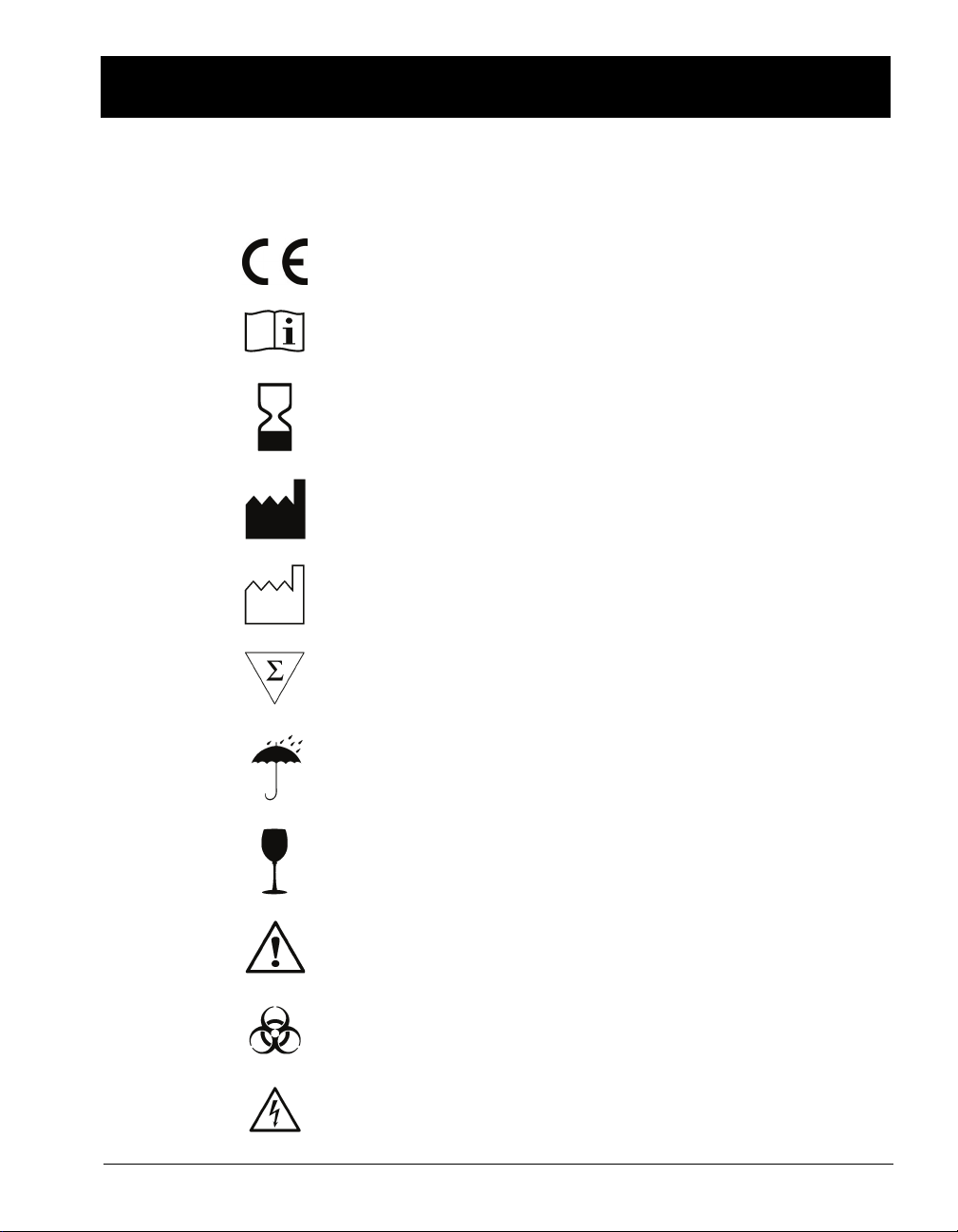
STANDARD SYMBOLS
The following table presents symbols that may appear in the instructions for
use or on the instrument, package inserts, or packaging.
CE-Marking of Conformity
Consult Instructions for Use
Use by
Manufacturer
Date of manufacture
Contains sufficient for <n> tests
Keep dry
Fragile, handle with care
Caution, consult accompanying documents
Biological risks
Electric shock warning
Page 8
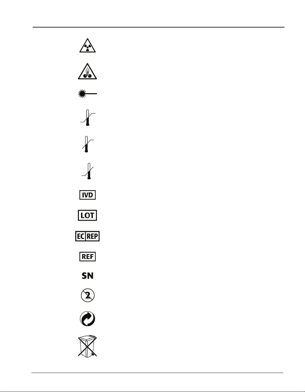
Radiation warning
Potential pinch-point warning
Laser
Temperature limitation
Upper limit of temperature
Lower limit of temperature
In Vitro Diagnostic Medical Device
Standard Symbols
Batch code
Authorized Representative in the European Community
Catalog number
Serial Number
Do not reuse
Recyclable
Separate collection for waste electrical and electronic
equipment
Page 9
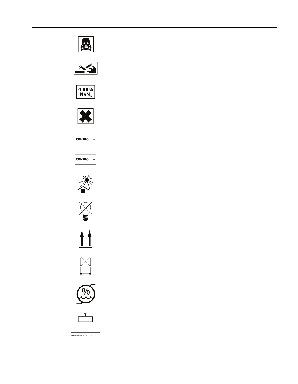
Standard Symbols
Very toxic
Corrosive
Sodium azide
Irritant
Positive control
Negative control
Keep away from sunlight
Protect from light
This way up
Do not stack
Humidity limitation
Fuse
Direct current
Page 10
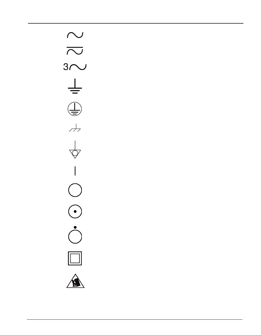
Alternating current
Both direct and alternating current
Three-phase alternating current
Earth (ground) terminal
Protective conductor terminal
Frame or chassis terminal
Equipotentiality
ON (supply)
Standard Symbols
OFF (supply)
ON (only for a component of the system equipment)
OFF (only for a component of the system equipment)
Equipment protected throughout by double insulation or
reinforced insulation (Equivalent to Class II of IEC 536)
Potential tip over/crush hazard
Page 11

TABLE OF CONTENTS
Standard Symbols......................................................................................................vi
List of Figures ............................................................................................................ix
List of Tables ............................................................................................................xiii
H
OW TO USE THIS MANUAL........................................................................................ 1-1
About This Chapter . . . . . . . . . . . . . . . . . . . . . . . . . . . . . . . . . . . . . . . . . . . . . 1-1
Chapter Contents . . . . . . . . . . . . . . . . . . . . . . . . . . . . . . . . . . . . . . . . . . . . . . . 1-1
Intended Audience . . . . . . . . . . . . . . . . . . . . . . . . . . . . . . . . . . . . . . . . . . . . . . 1-2
Purpose of the BacT/ALERT
Additional Supplies . . . . . . . . . . . . . . . . . . . . . . . . . . . . . . . . . . . . . . . . . . . . . . 1-3
Purpose of This Manual . . . . . . . . . . . . . . . . . . . . . . . . . . . . . . . . . . . . . . . . . . 1-3
Manual Organization. . . . . . . . . . . . . . . . . . . . . . . . . . . . . . . . . . . . . . . . . . . . . 1-4
Chapter Organization . . . . . . . . . . . . . . . . . . . . . . . . . . . . . . . . . . . . . . . . . . . . 1-5
Finding Topics. . . . . . . . . . . . . . . . . . . . . . . . . . . . . . . . . . . . . . . . . . . . . . . . . . 1-6
Typographic and Usage Conventions. . . . . . . . . . . . . . . . . . . . . . . . . . . . . . . . 1-6
Name and Titles. . . . . . . . . . . . . . . . . . . . . . . . . . . . . . . . . . . . . . . . . . . . . 1-6
Click . . . . . . . . . . . . . . . . . . . . . . . . . . . . . . . . . . . . . . . . . . . . . . . . . . . . . . 1-6
Press . . . . . . . . . . . . . . . . . . . . . . . . . . . . . . . . . . . . . . . . . . . . . . . . . . . . . 1-7
Procedural Steps . . . . . . . . . . . . . . . . . . . . . . . . . . . . . . . . . . . . . . . . . . . . 1-7
References . . . . . . . . . . . . . . . . . . . . . . . . . . . . . . . . . . . . . . . . . . . . . . . . 1-7
Select. . . . . . . . . . . . . . . . . . . . . . . . . . . . . . . . . . . . . . . . . . . . . . . . . . . . . 1-7
User Input . . . . . . . . . . . . . . . . . . . . . . . . . . . . . . . . . . . . . . . . . . . . . . . . . 1-8
Warnings, Cautions, and Information . . . . . . . . . . . . . . . . . . . . . . . . . . . . . . . . 1-8
®
3D 60 System. . . . . . . . . . . . . . . . . . . . . . . . . . 1-2
S
YSTEM OVERVIEW ..................................................................................................... 2-1
About This Chapter . . . . . . . . . . . . . . . . . . . . . . . . . . . . . . . . . . . . . . . . . . . . . 2-1
Chapter Contents . . . . . . . . . . . . . . . . . . . . . . . . . . . . . . . . . . . . . . . . . . . . . . . 2-1
Introduction . . . . . . . . . . . . . . . . . . . . . . . . . . . . . . . . . . . . . . . . . . . . . . . . . . . . 2-2
Hardware Configuration. . . . . . . . . . . . . . . . . . . . . . . . . . . . . . . . . . . . . . . 2-2
Software Configuration Options. . . . . . . . . . . . . . . . . . . . . . . . . . . . . . . . . 2-2
21 CFR Part 11 and HIPAA . . . . . . . . . . . . . . . . . . . . . . . . . . . . . . . . . . . . 2-3
Theory Of Operation . . . . . . . . . . . . . . . . . . . . . . . . . . . . . . . . . . . . . . . . . 2-3
Principle of Detection . . . . . . . . . . . . . . . . . . . . . . . . . . . . . . . . . . . . . . . . . . . . . 2-3
Electrical Warnings . . . . . . . . . . . . . . . . . . . . . . . . . . . . . . . . . . . . . . . . . . 2-4
Electrical Grounding . . . . . . . . . . . . . . . . . . . . . . . . . . . . . . . . . . . . . . . . . 2-6
Electrical and Electronic Recycling . . . . . . . . . . . . . . . . . . . . . . . . . . . . . . 2-7
Fuse Replacement. . . . . . . . . . . . . . . . . . . . . . . . . . . . . . . . . . . . . . . . . . . 2-7
®
BacT/ALERT
BacT/ALERT® 3D 60 User Manual i
95269
3D 60 Hardware . . . . . . . . . . . . . . . . . . . . . . . . . . . . . . . . . . . . 2-8
Page 12

Table of Contents
Instrument . . . . . . . . . . . . . . . . . . . . . . . . . . . . . . . . . . . . . . . . . . . . . . . . . . 2-8
Monitor . . . . . . . . . . . . . . . . . . . . . . . . . . . . . . . . . . . . . . . . . . . . . . . . . . . . . . . .2-9
Barcode Reader . . . . . . . . . . . . . . . . . . . . . . . . . . . . . . . . . . . . . . . . . . . . . . . . .2-9
Mouse. . . . . . . . . . . . . . . . . . . . . . . . . . . . . . . . . . . . . . . . . . . . . . . . . . . . . . . . .2-9
Keyboard . . . . . . . . . . . . . . . . . . . . . . . . . . . . . . . . . . . . . . . . . . . . . . . . . . . . . .2-9
UPS . . . . . . . . . . . . . . . . . . . . . . . . . . . . . . . . . . . . . . . . . . . . . . . . . . . . . . . . . .2-9
Backup Drive . . . . . . . . . . . . . . . . . . . . . . . . . . . . . . . . . . . . . . . . . . . . . . . . . . .2-9
UPS Port. . . . . . . . . . . . . . . . . . . . . . . . . . . . . . . . . . . . . . . . . . . . . . . . . . . . . .2-10
UPS Serial Port. . . . . . . . . . . . . . . . . . . . . . . . . . . . . . . . . . . . . . . . . . . . . . . . .2-10
Monitor Port . . . . . . . . . . . . . . . . . . . . . . . . . . . . . . . . . . . . . . . . . . . . . . . . . . .2-10
Mouse Ports . . . . . . . . . . . . . . . . . . . . . . . . . . . . . . . . . . . . . . . . . . . . . . . . . . .2-11
Keyboard Port. . . . . . . . . . . . . . . . . . . . . . . . . . . . . . . . . . . . . . . . . . . . . . . . . .2-11
Printer Port . . . . . . . . . . . . . . . . . . . . . . . . . . . . . . . . . . . . . . . . . . . . . . . . . . . .2-11
External Speaker Port. . . . . . . . . . . . . . . . . . . . . . . . . . . . . . . . . . . . . . . . . . . .2-11
Power Connector . . . . . . . . . . . . . . . . . . . . . . . . . . . . . . . . . . . . . . . . . . . . . . .2-11
Power Entry Module . . . . . . . . . . . . . . . . . . . . . . . . . . . . . . . . . . . . . . . . . . . . .2-11
Modem Port . . . . . . . . . . . . . . . . . . . . . . . . . . . . . . . . . . . . . . . . . . . . . . . . . . .2-11
LIS Port. . . . . . . . . . . . . . . . . . . . . . . . . . . . . . . . . . . . . . . . . . . . . . . . . . . . . . .2-11
Comm Port . . . . . . . . . . . . . . . . . . . . . . . . . . . . . . . . . . . . . . . . . . . . . . . . . . . .2-11
Instrument Specifications . . . . . . . . . . . . . . . . . . . . . . . . . . . . . . . . . . . . . 2-11
Electrical Power Services Requirements . . . . . . . . . . . . . . . . . . . . . . . . . . . . .2-11
Power Consumed in Watts . . . . . . . . . . . . . . . . . . . . . . . . . . . . . . . . . . . . . . . .2-12
Heat Dissipated . . . . . . . . . . . . . . . . . . . . . . . . . . . . . . . . . . . . . . . . . . . . . . . .2-12
Sound Emission . . . . . . . . . . . . . . . . . . . . . . . . . . . . . . . . . . . . . . . . . . . . . . . .2-12
Instrument Dimensions. . . . . . . . . . . . . . . . . . . . . . . . . . . . . . . . . . . . . . . . . . .2-12
Instrument Environmental Requirements . . . . . . . . . . . . . . . . . . . . . . . . . 2-12
Operating Temperature Range. . . . . . . . . . . . . . . . . . . . . . . . . . . . . . . . . . . . .2-12
Storage Temperature Range . . . . . . . . . . . . . . . . . . . . . . . . . . . . . . . . . . . . . .2-12
Operating Humidity Range . . . . . . . . . . . . . . . . . . . . . . . . . . . . . . . . . . . . . . . .2-12
Storage Humidity Range. . . . . . . . . . . . . . . . . . . . . . . . . . . . . . . . . . . . . . . . . .2-12
Maximum Operating and Storage Altitude . . . . . . . . . . . . . . . . . . . . . . . . . . . .2-12
Pollution Degree 2 in accordance with IEC 664 . . . . . . . . . . . . . . . . . . . . . . . .2-12
Overvoltage Category II per IEC 664 . . . . . . . . . . . . . . . . . . . . . . . . . . . . . . . .2-12
Instrument Installation and Setup . . . . . . . . . . . . . . . . . . . . . . . . . . . . . . . 2-13
BacT/ALERT
®
3D 60 Software . . . . . . . . . . . . . . . . . . . . . . . . . . . . . . . . . . . . 2-13
Monitor Screens . . . . . . . . . . . . . . . . . . . . . . . . . . . . . . . . . . . . . . . . . . . . 2-13
Common Screen Elements . . . . . . . . . . . . . . . . . . . . . . . . . . . . . . . . . . . . 2-14
Icon. . . . . . . . . . . . . . . . . . . . . . . . . . . . . . . . . . . . . . . . . . . . . . . . . . . . . . . . . .2-14
Button . . . . . . . . . . . . . . . . . . . . . . . . . . . . . . . . . . . . . . . . . . . . . . . . . . . . . . . .2-14
Common System Buttons. . . . . . . . . . . . . . . . . . . . . . . . . . . . . . . . . . . . . . . . .2-14
Scroll Button . . . . . . . . . . . . . . . . . . . . . . . . . . . . . . . . . . . . . . . . . . . . . . . . . . .2-15
Slidebar Switch. . . . . . . . . . . . . . . . . . . . . . . . . . . . . . . . . . . . . . . . . . . . . . . . .2-15
Anchor Display/Scroll Buttons . . . . . . . . . . . . . . . . . . . . . . . . . . . . . . . . . . . . .2-15
Text Entry Field. . . . . . . . . . . . . . . . . . . . . . . . . . . . . . . . . . . . . . . . . . . . . . . . .2-16
SYSTEM INSTALLATION ................................................................................................ 3-1
About This Chapter . . . . . . . . . . . . . . . . . . . . . . . . . . . . . . . . . . . . . . . . . . . . . . 3-1
ii BacT/ALERT® 3D 60 User Manual
95269
Page 13

Table of Contents
Chapter Contents . . . . . . . . . . . . . . . . . . . . . . . . . . . . . . . . . . . . . . . . . . . . . . . 3-1
Preparation . . . . . . . . . . . . . . . . . . . . . . . . . . . . . . . . . . . . . . . . . . . . . . . . . . . . 3-2
Verifying Site Requirements Are Met. . . . . . . . . . . . . . . . . . . . . . . . . . . . . 3-2
Verifying Contents . . . . . . . . . . . . . . . . . . . . . . . . . . . . . . . . . . . . . . . . . . . 3-2
Installation. . . . . . . . . . . . . . . . . . . . . . . . . . . . . . . . . . . . . . . . . . . . . . . . . . . . . 3-3
Setting the AC Power . . . . . . . . . . . . . . . . . . . . . . . . . . . . . . . . . . . . . . . . 3-3
Choosing Instrument Location . . . . . . . . . . . . . . . . . . . . . . . . . . . . . . . . . 3-6
Making Instrument Connections . . . . . . . . . . . . . . . . . . . . . . . . . . . . . . . . 3-7
Powering Up the Instrument . . . . . . . . . . . . . . . . . . . . . . . . . . . . . . . . . . . 3-9
Configuring the Instrument . . . . . . . . . . . . . . . . . . . . . . . . . . . . . . . . . . . 3-10
Setting the Temperature . . . . . . . . . . . . . . . . . . . . . . . . . . . . . . . . . . . . . 3-10
Checking for Errors . . . . . . . . . . . . . . . . . . . . . . . . . . . . . . . . . . . . . . . . . 3-10
Functional Testing. . . . . . . . . . . . . . . . . . . . . . . . . . . . . . . . . . . . . . . . . . . . . . 3-10
Modem Functional Test . . . . . . . . . . . . . . . . . . . . . . . . . . . . . . . . . . . . . . 3-10
Barcode Reader Functional Test . . . . . . . . . . . . . . . . . . . . . . . . . . . . . . . 3-11
®
UPS Functional Test (BacT/ALERT
3D 60 Only, APC UPS 650) . . . . . 3-12
Installing the Optional Restraint . . . . . . . . . . . . . . . . . . . . . . . . . . . . . . . . . . . 3-12
B
ASIC FUNCTIONS....................................................................................................... 4-1
About This Chapter . . . . . . . . . . . . . . . . . . . . . . . . . . . . . . . . . . . . . . . . . . . . . 4-1
Chapter Contents . . . . . . . . . . . . . . . . . . . . . . . . . . . . . . . . . . . . . . . . . . . . . . . 4-1
Introduction . . . . . . . . . . . . . . . . . . . . . . . . . . . . . . . . . . . . . . . . . . . . . . . . . . . . 4-2
Monitoring the System . . . . . . . . . . . . . . . . . . . . . . . . . . . . . . . . . . . . . . . . . . . 4-2
Main Screen Introduction. . . . . . . . . . . . . . . . . . . . . . . . . . . . . . . . . . . . . . 4-2
Background Color. . . . . . . . . . . . . . . . . . . . . . . . . . . . . . . . . . . . . . . . . . . . . . . .4-3
Instrument Icon. . . . . . . . . . . . . . . . . . . . . . . . . . . . . . . . . . . . . . . . . . . . . . . . . .4-4
Bottle Count Table . . . . . . . . . . . . . . . . . . . . . . . . . . . . . . . . . . . . . . . . . . . . . . .4-4
Viewing Faults . . . . . . . . . . . . . . . . . . . . . . . . . . . . . . . . . . . . . . . . . . . . . . 4-5
Viewing the Cell Status Screen . . . . . . . . . . . . . . . . . . . . . . . . . . . . . . . . 4-6
Understanding the View Cell Status Screen Display . . . . . . . . . . . . . . . . . . . . .4-6
Text/Data Entry . . . . . . . . . . . . . . . . . . . . . . . . . . . . . . . . . . . . . . . . . . . . . . . . . 4-8
Common Text Fields and Field Limits . . . . . . . . . . . . . . . . . . . . . . . . . . . . . . . .4-8
Using the Barcode Scanner to Enter Data. . . . . . . . . . . . . . . . . . . . . . . . . 4-8
Manually Entering Text into a Data Entry Field (Keyboard). . . . . . . . . . . . 4-9
Loading Bottles . . . . . . . . . . . . . . . . . . . . . . . . . . . . . . . . . . . . . . . . . . . . . . . . 4-10
Loading Bottles . . . . . . . . . . . . . . . . . . . . . . . . . . . . . . . . . . . . . . . . . . . . 4-10
Changing the Maximum Test Time (Individual Bottles) . . . . . . . . . . . . . . 4-13
Handling Anonymous Bottles. . . . . . . . . . . . . . . . . . . . . . . . . . . . . . . . . . 4-14
Unloading Bottles . . . . . . . . . . . . . . . . . . . . . . . . . . . . . . . . . . . . . . . . . . . . . . 4-14
Unloading Bottles. . . . . . . . . . . . . . . . . . . . . . . . . . . . . . . . . . . . . . . . . . . 4-15
Handling Unconfirmed Positive Bottles (False Positives) . . . . . . . . . . . . 4-17
BacT/ALERT® 3D 60 User Manual iii
95269
Page 14

Table of Contents
EDITING TEST DATA .................................................................................................... 5-1
Accessing the Setup Screen Function Buttons . . . . . . . . . . . . . . . . . . . . . . . . 4-18
Accessing the Setup Screen. . . . . . . . . . . . . . . . . . . . . . . . . . . . . . . . . . . 4-18
Inactivity Timeout for all Setup Screens . . . . . . . . . . . . . . . . . . . . . . . . . . . . . .4-19
Setup Screen Function Buttons . . . . . . . . . . . . . . . . . . . . . . . . . . . . . . . . 4-19
Viewing and Printing . . . . . . . . . . . . . . . . . . . . . . . . . . . . . . . . . . . . . . . . . . . .4-21
Introduction . . . . . . . . . . . . . . . . . . . . . . . . . . . . . . . . . . . . . . . . . . . . . . . . 4-21
Viewing Bottle Data . . . . . . . . . . . . . . . . . . . . . . . . . . . . . . . . . . . . . . . . . . . . .4-21
Viewing/Printing Reports . . . . . . . . . . . . . . . . . . . . . . . . . . . . . . . . . . . . . . . . .4-21
Viewing/Printing Graphs . . . . . . . . . . . . . . . . . . . . . . . . . . . . . . . . . . . . . . . . . .4-21
Using the Print Screen Function. . . . . . . . . . . . . . . . . . . . . . . . . . . . . . . . . . . .4-21
Viewing and Printing Test Data. . . . . . . . . . . . . . . . . . . . . . . . . . . . . . . . . 4-22
Viewing and Printing Bottle Graphs . . . . . . . . . . . . . . . . . . . . . . . . . . . . . 4-29
Display Bottle Readings . . . . . . . . . . . . . . . . . . . . . . . . . . . . . . . . . . . . . . 4-31
Sending/Requesting LIS Information . . . . . . . . . . . . . . . . . . . . . . . . . . . . . . . . 4-36
Sending Results to the LIS . . . . . . . . . . . . . . . . . . . . . . . . . . . . . . . . . . . . 4-36
Requesting Information from the LIS . . . . . . . . . . . . . . . . . . . . . . . . . . . . 4-36
About This Chapter . . . . . . . . . . . . . . . . . . . . . . . . . . . . . . . . . . . . . . . . . . . . . . 5-1
Chapter Contents . . . . . . . . . . . . . . . . . . . . . . . . . . . . . . . . . . . . . . . . . . . . . . .5-1
Viewing/Editing Bottle Data . . . . . . . . . . . . . . . . . . . . . . . . . . . . . . . . . . . . . . . . 5-2
Introduction . . . . . . . . . . . . . . . . . . . . . . . . . . . . . . . . . . . . . . . . . . . . . . . . . 5-2
Selecting Bottles Using the Edit Cell Contents Button . . . . . . . . . . . . . . . . 5-3
Selecting Bottles Using the Select Bottle to Edit/Graph Button . . . . . . . . . 5-4
Editing Bottle Details Using the Edit Bottle Detail Screen. . . . . . . . . . . . . . 5-5
Edit Bottle ID Field . . . . . . . . . . . . . . . . . . . . . . . . . . . . . . . . . . . . . . . . . . . . . . .5-6
View Accession Number Field . . . . . . . . . . . . . . . . . . . . . . . . . . . . . . . . . . . . . .5-6
View Hospital ID Field. . . . . . . . . . . . . . . . . . . . . . . . . . . . . . . . . . . . . . . . . . . . .5-6
View Patient First Name Field . . . . . . . . . . . . . . . . . . . . . . . . . . . . . . . . . . . . . .5-6
View Patient Last Name Field. . . . . . . . . . . . . . . . . . . . . . . . . . . . . . . . . . . . . . .5-6
Edit Load Status Slidebar Switch . . . . . . . . . . . . . . . . . . . . . . . . . . . . . . . . . . . .5-6
Edit Maximum Test Time Scroll Buttons. . . . . . . . . . . . . . . . . . . . . . . . . . . . . . .5-7
Edit Bottle Type Scroll Button . . . . . . . . . . . . . . . . . . . . . . . . . . . . . . . . . . . . . . .5-7
View Cell Location Icon . . . . . . . . . . . . . . . . . . . . . . . . . . . . . . . . . . . . . . . . . . .5-7
View First Loaded Time Icon . . . . . . . . . . . . . . . . . . . . . . . . . . . . . . . . . . . . . . .5-8
View Last Unloaded Time Icon. . . . . . . . . . . . . . . . . . . . . . . . . . . . . . . . . . . . . .5-8
View Time of Last Bottle Reading Icon. . . . . . . . . . . . . . . . . . . . . . . . . . . . . . . .5-8
View Test Time Icon . . . . . . . . . . . . . . . . . . . . . . . . . . . . . . . . . . . . . . . . . . . . . .5-8
View Test Result Icon. . . . . . . . . . . . . . . . . . . . . . . . . . . . . . . . . . . . . . . . . . . . .5-8
Edit Test Result Button. . . . . . . . . . . . . . . . . . . . . . . . . . . . . . . . . . . . . . . . . . . .5-9
Graph Bottle Readings Button . . . . . . . . . . . . . . . . . . . . . . . . . . . . . . . . . . . . .5-10
View Algorithm/Polynomial Icon . . . . . . . . . . . . . . . . . . . . . . . . . . . . . . . . . . . .5-10
View How Determined/Positivity Index Icon . . . . . . . . . . . . . . . . . . . . . . . . . . .5-10
Editing Data Relationships . . . . . . . . . . . . . . . . . . . . . . . . . . . . . . . . . . . . . . . .5-11
Introduction . . . . . . . . . . . . . . . . . . . . . . . . . . . . . . . . . . . . . . . . . . . . . . . . 5-11
iv BacT/ALERT® 3D 60 User Manual
95269
Page 15

Table of Contents
Initiating the Edit Data Relationships Function . . . . . . . . . . . . . . . . . . . . 5-12
Editing Bottle ID to Accession Number Relationships . . . . . . . . . . . . . . . 5-13
Attaching Bottle IDs Without an Accession Number to an Accession Number 5-14
Moving a Bottle ID Association from one Accession Number to Another . . . . .5-14
Editing Accession Number to Hospital ID Relationships . . . . . . . . . . . . . 5-15
Attaching Accession Numbers Without a Hospital ID to a Hospital ID . . . . . . .5-16
Moving an Accession Number Association from one Hospital ID to Another . .5-16
Editing Hospital ID to Patient Name Relationships . . . . . . . . . . . . . . . . . 5-17
S
OFTWARE CONFIGURATION........................................................................................ 6-1
About This Chapter . . . . . . . . . . . . . . . . . . . . . . . . . . . . . . . . . . . . . . . . . . . . . 6-1
Chapter Contents . . . . . . . . . . . . . . . . . . . . . . . . . . . . . . . . . . . . . . . . . . . . . . . 6-1
Setting the Maximum Test Time . . . . . . . . . . . . . . . . . . . . . . . . . . . . . . . . . . . . 6-2
Setting the Audible Alarms . . . . . . . . . . . . . . . . . . . . . . . . . . . . . . . . . . . . . . . . 6-3
Priority of Alarms . . . . . . . . . . . . . . . . . . . . . . . . . . . . . . . . . . . . . . . . . . . . 6-5
Terminating an Instrument Alarm . . . . . . . . . . . . . . . . . . . . . . . . . . . . . . . 6-5
Changing the System Password. . . . . . . . . . . . . . . . . . . . . . . . . . . . . . . . . . . . 6-5
Initiating Manual Backup. . . . . . . . . . . . . . . . . . . . . . . . . . . . . . . . . . . . . . . . . . 6-7
Configuring Report Screens . . . . . . . . . . . . . . . . . . . . . . . . . . . . . . . . . . . . . . . 6-9
Introduction . . . . . . . . . . . . . . . . . . . . . . . . . . . . . . . . . . . . . . . . . . . . . . . . 6-9
Entering Report Labels . . . . . . . . . . . . . . . . . . . . . . . . . . . . . . . . . . . . . . . 6-9
Configuring Report Contents . . . . . . . . . . . . . . . . . . . . . . . . . . . . . . . . . . 6-13
Load Report Configuration Screen . . . . . . . . . . . . . . . . . . . . . . . . . . . . . . . . . .6-16
Status Report Configuration Screen. . . . . . . . . . . . . . . . . . . . . . . . . . . . . . . . .6-17
Unload Report Configuration Screen . . . . . . . . . . . . . . . . . . . . . . . . . . . . . . . .6-18
Viewing and Printing Calibration Data . . . . . . . . . . . . . . . . . . . . . . . . . . . 6-19
Viewing and Printing Calibration History . . . . . . . . . . . . . . . . . . . . . . . . . 6-22
SYSTEM MAINTENANCE ............................................................................................... 7-1
About This Chapter . . . . . . . . . . . . . . . . . . . . . . . . . . . . . . . . . . . . . . . . . . . . . 7-1
Chapter Contents . . . . . . . . . . . . . . . . . . . . . . . . . . . . . . . . . . . . . . . . . . . . . . . 7-1
Hardware Maintenance. . . . . . . . . . . . . . . . . . . . . . . . . . . . . . . . . . . . . . . . . . . 7-2
Preventative Maintenance . . . . . . . . . . . . . . . . . . . . . . . . . . . . . . . . . . . . . 7-2
Safety Precautions and Procedures . . . . . . . . . . . . . . . . . . . . . . . . . . . . . 7-2
Spill Cleanup . . . . . . . . . . . . . . . . . . . . . . . . . . . . . . . . . . . . . . . . . . . . . . . . . . .7-3
Disinfection Procedure for Spills Onto the Instrument . . . . . . . . . . . . . . . . . . . .7-3
Disinfection Procedure for Spills Within the Instrument . . . . . . . . . . . . . . . . . . . 7-4
Using the Keyboard in Place of the Mouse . . . . . . . . . . . . . . . . . . . . . . . . 7-6
UPS On/Off Button Location . . . . . . . . . . . . . . . . . . . . . . . . . . . . . . . . . . . 7-7
Instrument Reboot/Shutdown . . . . . . . . . . . . . . . . . . . . . . . . . . . . . . . . . . 7-7
Shutdown Method 1 . . . . . . . . . . . . . . . . . . . . . . . . . . . . . . . . . . . . . . . . . . . . . . 7-8
Shutdown Method 2 . . . . . . . . . . . . . . . . . . . . . . . . . . . . . . . . . . . . . . . . . . . . . . 7-8
Shutdown Method 3 . . . . . . . . . . . . . . . . . . . . . . . . . . . . . . . . . . . . . . . . . . . . . . 7-9
BacT/ALERT® 3D 60 User Manual v
95269
Page 16

Table of Contents
S
Shutdown Method 4 . . . . . . . . . . . . . . . . . . . . . . . . . . . . . . . . . . . . . . . . . . . . . .7-9
Instrument Startup . . . . . . . . . . . . . . . . . . . . . . . . . . . . . . . . . . . . . . . . . . . 7-9
Software Maintenance . . . . . . . . . . . . . . . . . . . . . . . . . . . . . . . . . . . . . . . . . . . . 7-9
Introduction . . . . . . . . . . . . . . . . . . . . . . . . . . . . . . . . . . . . . . . . . . . . . . . . . 7-9
Restarting the Incubation Chamber . . . . . . . . . . . . . . . . . . . . . . . . . . . . . 7-10
Setting and Formatting the System Date and Time . . . . . . . . . . . . . . . . . 7-11
Enabling and Disabling Racks and Cells . . . . . . . . . . . . . . . . . . . . . . . . . 7-13
Relocating Bottles. . . . . . . . . . . . . . . . . . . . . . . . . . . . . . . . . . . . . . . . . . . . . . .7-14
Adjusting an Instrument’s Temperature . . . . . . . . . . . . . . . . . . . . . . . . . . 7-15
Checking an Instrument's Temperature . . . . . . . . . . . . . . . . . . . . . . . . . . . . . .7-15
Setting the Optimal Temperature for an Instrument . . . . . . . . . . . . . . . . . . . . .7-17
Calibrating an Instrument's Temperature . . . . . . . . . . . . . . . . . . . . . . . . . . . . .7-17
Calibrating an Instrument Cell. . . . . . . . . . . . . . . . . . . . . . . . . . . . . . . . . . 7-18
Locating a Cell Which Failed Calibration . . . . . . . . . . . . . . . . . . . . . . . . . . . . .7-18
Viewing a Cell's Readings and/or Calibrating a Cell. . . . . . . . . . . . . . . . . . . . .7-19
Viewing Incubation Chamber Information . . . . . . . . . . . . . . . . . . . . . . . . . 7-22
YSTEM TROUBLESHOOTING .......................................................................................8-1
About This Chapter . . . . . . . . . . . . . . . . . . . . . . . . . . . . . . . . . . . . . . . . . . . . . . 8-1
Chapter Contents . . . . . . . . . . . . . . . . . . . . . . . . . . . . . . . . . . . . . . . . . . . . . . .8-1
Introduction . . . . . . . . . . . . . . . . . . . . . . . . . . . . . . . . . . . . . . . . . . . . . . . . . . . . 8-2
Fault Codes . . . . . . . . . . . . . . . . . . . . . . . . . . . . . . . . . . . . . . . . . . . . . . . . . . . .8-3
Instrument Fault Codes. . . . . . . . . . . . . . . . . . . . . . . . . . . . . . . . . . . . . . . . 8-3
Instrument Status Codes . . . . . . . . . . . . . . . . . . . . . . . . . . . . . . . . . . . . . 8-16
Operator Error Codes . . . . . . . . . . . . . . . . . . . . . . . . . . . . . . . . . . . . . . . . 8-18
Bottle Problems. . . . . . . . . . . . . . . . . . . . . . . . . . . . . . . . . . . . . . . . . . . . . 8-29
User Output Device Problems . . . . . . . . . . . . . . . . . . . . . . . . . . . . . . . . . 8-29
21 CFR P
ART 11 MODE..............................................................................................9-1
About This Chapter . . . . . . . . . . . . . . . . . . . . . . . . . . . . . . . . . . . . . . . . . . . . . . 9-1
Chapter Contents . . . . . . . . . . . . . . . . . . . . . . . . . . . . . . . . . . . . . . . . . . . . . . .9-1
Log In/Out of System — 21 CFR Part 11 Mode. . . . . . . . . . . . . . . . . . . . . . . . . 9-2
Logging In for the First Time . . . . . . . . . . . . . . . . . . . . . . . . . . . . . . . . . . . . 9-2
Logging In . . . . . . . . . . . . . . . . . . . . . . . . . . . . . . . . . . . . . . . . . . . . . . . . . . 9-6
Inactivity Timeout . . . . . . . . . . . . . . . . . . . . . . . . . . . . . . . . . . . . . . . . . . . . 9-7
Login Errors . . . . . . . . . . . . . . . . . . . . . . . . . . . . . . . . . . . . . . . . . . . . . . . . 9-7
Change Password. . . . . . . . . . . . . . . . . . . . . . . . . . . . . . . . . . . . . . . . . . . . 9-8
Change Password Errors . . . . . . . . . . . . . . . . . . . . . . . . . . . . . . . . . . . . . . 9-9
Logging Out . . . . . . . . . . . . . . . . . . . . . . . . . . . . . . . . . . . . . . . . . . . . . . . 9-12
Configuring Users — 21 CFR Part 11 Mode . . . . . . . . . . . . . . . . . . . . . . . . . . 9-12
Adding a User . . . . . . . . . . . . . . . . . . . . . . . . . . . . . . . . . . . . . . . . . . . . . . 9-13
Deleting a User . . . . . . . . . . . . . . . . . . . . . . . . . . . . . . . . . . . . . . . . . . . . . 9-15
vi BacT/ALERT® 3D 60 User Manual
95269
Page 17

Table of Contents
Deleting More Than One User . . . . . . . . . . . . . . . . . . . . . . . . . . . . . . . . .9-16
Clearing a User Password . . . . . . . . . . . . . . . . . . . . . . . . . . . . . . . . . . . . 9-16
Clearing More Than One User Password. . . . . . . . . . . . . . . . . . . . . . . . .9-17
Audit Trail . . . . . . . . . . . . . . . . . . . . . . . . . . . . . . . . . . . . . . . . . . . . . . . . . . . . 9-18
Accessing the Audit Trail . . . . . . . . . . . . . . . . . . . . . . . . . . . . . . . . . . . . . 9-20
M
YCOBACTERIAL TESTING......................................................................................... 10-1
About This Chapter . . . . . . . . . . . . . . . . . . . . . . . . . . . . . . . . . . . . . . . . . . . . 10-1
Chapter Contents . . . . . . . . . . . . . . . . . . . . . . . . . . . . . . . . . . . . . . . . . . . . . . 10-1
System Description . . . . . . . . . . . . . . . . . . . . . . . . . . . . . . . . . . . . . . . . . . . . . 10-2
Intended Use . . . . . . . . . . . . . . . . . . . . . . . . . . . . . . . . . . . . . . . . . . . . . . 10-2
Overview . . . . . . . . . . . . . . . . . . . . . . . . . . . . . . . . . . . . . . . . . . . . . . . . . 10-2
BacT/ALERT
Circulation Fan . . . . . . . . . . . . . . . . . . . . . . . . . . . . . . . . . . . . . . . . . . . . . . . . .10-3
Installation Procedures and Special Requirements . . . . . . . . . . . . . . . . . . . . .10-3
®
3D 60 Instrument . . . . . . . . . . . . . . . . . . . . . . . . . . . . . . . 10-3
BacT/ALERT® 3D 60 Software . . . . . . . . . . . . . . . . . . . . . . . . . . . . . . . . 10-4
Barcodes . . . . . . . . . . . . . . . . . . . . . . . . . . . . . . . . . . . . . . . . . . . . . . . . . . . . .10-4
Set Maximum Test Time. . . . . . . . . . . . . . . . . . . . . . . . . . . . . . . . . . . . . . . . . . 10-4
Positive Detection Algorithm. . . . . . . . . . . . . . . . . . . . . . . . . . . . . . . . . . . . . . . 10-4
Bottle Status . . . . . . . . . . . . . . . . . . . . . . . . . . . . . . . . . . . . . . . . . . . . . . . . . . .10-4
System Startup . . . . . . . . . . . . . . . . . . . . . . . . . . . . . . . . . . . . . . . . . . . . . . . . 10-5
General Information . . . . . . . . . . . . . . . . . . . . . . . . . . . . . . . . . . . . . . . . . 10-5
MB Configuration . . . . . . . . . . . . . . . . . . . . . . . . . . . . . . . . . . . . . . . . . . . . . . .10-5
Limitations of the Test . . . . . . . . . . . . . . . . . . . . . . . . . . . . . . . . . . . . . . . . . . .10-5
Service and Maintenance . . . . . . . . . . . . . . . . . . . . . . . . . . . . . . . . . . . . . . . . .10-6
Theory of Operation. . . . . . . . . . . . . . . . . . . . . . . . . . . . . . . . . . . . . . . . . 10-6
Principle of Detection . . . . . . . . . . . . . . . . . . . . . . . . . . . . . . . . . . . . . . . . . . . .10-6
Safety Features . . . . . . . . . . . . . . . . . . . . . . . . . . . . . . . . . . . . . . . . . . . . 10-7
General Precautions. . . . . . . . . . . . . . . . . . . . . . . . . . . . . . . . . . . . . . . . . . . . .10-8
Spill Cleanup . . . . . . . . . . . . . . . . . . . . . . . . . . . . . . . . . . . . . . . . . . . . . . . . . .10-8
Disinfection Procedure for Spills Within/Onto the Instrument. . . . . . . . . . . . . .10-8
UNPACKING INSTRUCTIONS..........................................................................................A-1
BacT/ALERT® 3D 60 Unpacking Instructions. . . . . . . . . . . . . . . . . . . . . . . . . . A-1
P
ART CHECKLIST ........................................................................................................B-1
BacT/ALERT
®
3D 60 Part Checklist . . . . . . . . . . . . . . . . . . . . . . . . . . . . . . . . . B-1
Contents . . . . . . . . . . . . . . . . . . . . . . . . . . . . . . . . . . . . . . . . . . . . . . . . . . B-1
Optional Equipment . . . . . . . . . . . . . . . . . . . . . . . . . . . . . . . . . . . . . . . . . . B-1
Recommended Tools. . . . . . . . . . . . . . . . . . . . . . . . . . . . . . . . . . . . . . . . . B-1
INSTALLATION CHECKLIST ...........................................................................................C-1
BacT/ALERT® 3D 60 Installation Checklist. . . . . . . . . . . . . . . . . . . . . . . . . . . . C-1
BacT/ALERT® 3D 60 User Manual vii
95269
Page 18

Table of Contents
INTERNATIONAL CHARACTER ENTRY ............................................................................D-1
B
About This Chapter . . . . . . . . . . . . . . . . . . . . . . . . . . . . . . . . . . . . . . . . . . . . . .D-1
Chapter Contents . . . . . . . . . . . . . . . . . . . . . . . . . . . . . . . . . . . . . . . . . . . . . . .D-1
International Character Entry . . . . . . . . . . . . . . . . . . . . . . . . . . . . . . . . . . . . . . .D-2
Entering International Characters . . . . . . . . . . . . . . . . . . . . . . . . . . . . . . . .D-3
OTTLE QUALITY CONTROL.........................................................................................E-1
About This Chapter . . . . . . . . . . . . . . . . . . . . . . . . . . . . . . . . . . . . . . . . . . . . . .E-1
Chapter Contents . . . . . . . . . . . . . . . . . . . . . . . . . . . . . . . . . . . . . . . . . . . . . . .E-1
BacT/ALERT
®
Culture Bottles . . . . . . . . . . . . . . . . . . . . . . . . . . . . . . . . . . . . . .E-2
Introduction . . . . . . . . . . . . . . . . . . . . . . . . . . . . . . . . . . . . . . . . . . . . . . . . .E-2
Flip Cap . . . . . . . . . . . . . . . . . . . . . . . . . . . . . . . . . . . . . . . . . . . . . . . . . . . . . . E-3
Stopper/Seal. . . . . . . . . . . . . . . . . . . . . . . . . . . . . . . . . . . . . . . . . . . . . . . . . . . E-3
Bottle. . . . . . . . . . . . . . . . . . . . . . . . . . . . . . . . . . . . . . . . . . . . . . . . . . . . . . . . . E-3
Volume Designations . . . . . . . . . . . . . . . . . . . . . . . . . . . . . . . . . . . . . . . . . . . . E-3
Barcode . . . . . . . . . . . . . . . . . . . . . . . . . . . . . . . . . . . . . . . . . . . . . . . . . . . . . . E-3
Sensor . . . . . . . . . . . . . . . . . . . . . . . . . . . . . . . . . . . . . . . . . . . . . . . . . . . . . . . E-3
Limitations of the Test. . . . . . . . . . . . . . . . . . . . . . . . . . . . . . . . . . . . . . . . . . . . E-4
Quality Control of Growth Performance . . . . . . . . . . . . . . . . . . . . . . . . . . .E-4
Blood Culture Bottles (SA, SN, FA, FN, and PF) . . . . . . . . . . . . . . . . . . . . . . . E-4
Mycobacteria Culture Bottles (MB and MP) . . . . . . . . . . . . . . . . . . . . . . . . . . . E-5
GLOSSARY................................................................................................... GLOSSARY-1
I
NDEX .................................................................................................................. INDEX-1
viii BacT/ALERT® 3D 60 User Manual
95269
Page 19

LIST OF FIGURES
Figure 1-1: Procedure Icon ...................................................................................................1-7
Figure 2-1: Electrical Grounding Requirements ...................................................................2-7
Figure 2-2: Instrument Front View ........................................................................................2-8
Figure 2-3: Instrument Rear View ......................................................................................2-10
Figure 2-4: Button Examples ..............................................................................................2-14
Figure 2-5: Scroll Button .....................................................................................................2-15
Figure 2-6: Slidebar Switch ................................................................................................2-15
Figure 2-7: Anchor Display/Scroll Buttons ..........................................................................2-16
Figure 3-1: Power Entry Module with Fuse Holder Removed ..............................................3-3
Figure 3-2: PEM with 115 VAC Version ...............................................................................3-4
Figure 3-3: PEM with 230 VAC Version ...............................................................................3-5
Figure 3-4: Additional Fuse Holder Views ............................................................................3-6
Figure 3-5: Installation and Setup Diagram — Port and Power Connections .......................3-9
Figure 3-6: Modem Configuration and Dip Switch Settings ................................................3-11
Figure 3-7: Countertop/Surface Mounting Diagram ...........................................................3-13
Figure 3-8: Mounting Surface Diagram ..............................................................................3-13
Figure 3-9: Mounting Surface (Drilling) Template ...............................................................3-14
Figure 4-1: Main Screen .......................................................................................................4-3
Figure 4-2: Instrument Icons ................................................................................................4-4
Figure 4-3: Bottle Count Table/Unload Buttons ....................................................................4-5
Figure 4-4: View Cell Status Screen ....................................................................................4-6
Figure 4-5: Disabled Cell ......................................................................................................4-7
Figure 4-6: Main Screen — Load Mode .............................................................................4-10
Figure 4-7: Change Maximum Test Time Screen ...............................................................4-13
Figure 4-8: Main Screen — Unload Mode ..........................................................................4-15
Figure 4-9: Setup Screen ...................................................................................................4-18
Figure 4-10: Report Selection Screen ..................................................................................4-22
Figure 4-11: Sample Report Screen .....................................................................................4-24
Figure 4-12: Find Text Screen ..............................................................................................4-27
Figure 4-13: Save to File Screen ..........................................................................................4-28
Figure 4-14: Select Bottle to Edit/Graph Screen ..................................................................4-29
Figure 4-15: Graph Bottle Readings Screen ........................................................................4-30
BacT/ALERT® 3D 60 User Manual ix
95269
Page 20

Figure 4-16: Bottle Readings Screen .................................................................................. 4-32
Figure 4-17: Find Text Screen ............................................................................................. 4-34
Figure 4-18: Save to File Screen ......................................................................................... 4-35
Figure 5-1: Edit Cell Contents Screen ................................................................................. 5-3
Figure 5-2: Select Bottle to Edit/Graph Screen ................................................................... 5-4
Figure 5-3: Edit Bottle Detail Screen ................................................................................... 5-5
Figure 5-4: Edit Test Result Screen .................................................................................... 5-9
Figure 5-5: Edit Data Relationships Screen ...................................................................... 5-12
Figure 5-6: Edit Bottle ID to Accession Number Relationships Screen ............................. 5-13
Figure 5-7: Edit Accession Number to Hospital ID Relationships Screen ......................... 5-15
Figure 5-8: Edit Hospital ID to Patient Name Relationships Screen .................................. 5-17
Figure 6-1: Set Maximum Test Time Screen ....................................................................... 6-2
Figure 6-2: Set Audible Alarm Options Screen .................................................................... 6-4
Figure 6-3: Change Password Screen ................................................................................ 6-6
Figure 6-4: Padlock Icon (Full Open Position) ..................................................................... 6-6
Figure 6-5: Padlock Icon (Half Open Position) .................................................................... 6-7
Figure 6-6: Padlock Icon (Closed Position) ......................................................................... 6-7
Figure 6-7: Backup Management Screen ............................................................................ 6-8
Figure 6-8: Backup in Progress Icon ................................................................................... 6-8
Figure 6-9: Report Selection Screen ................................................................................. 6-10
Figure 6-10: Report Label Entry Screen .............................................................................. 6-11
Figure 6-11: Report Selection Screen ................................................................................. 6-14
Figure 6-12: Load Report Configuration Screen .................................................................. 6-16
Figure 6-13: Status Report Configuration Screen ............................................................... 6-17
Figure 6-14: Unload Report Configuration Screen .............................................................. 6-18
Figure 6-15: Report Selection Screen ................................................................................. 6-19
Figure 6-16: Cell Calibration Report Screen ........................................................................ 6-20
Figure 6-17: View Window ................................................................................................... 6-21
Figure 6-18: Report Selection Screen ................................................................................. 6-22
Figure 6-19: Calibration History Screen .............................................................................. 6-23
Figure 7-1: View Cell Status Screen .................................................................................. 7-11
Figure 7-2: Set Date/Time Screen ..................................................................................... 7-12
Figure 7-3: Enable/Disable Rack or Cell Screen ............................................................... 7-13
Figure 7-4: Reference Thermometer ................................................................................. 7-15
x BacT/ALERT® 3D 60 User Manual
95269
Page 21

Figure 7-5: Calibrate Instrument Temperature Screen .......................................................7-16
Figure 7-6: Calibrate Cell Screen .......................................................................................7-19
Figure 7-7: View Incubation Chamber Information Screen ................................................7-23
Figure 8-1: Instrument Icon with Fault Codes ......................................................................8-3
Figure 8-2: Instrument Status Code 710 ............................................................................8-16
Figure 8-3: Operator Error Code 911 .................................................................................8-18
Figure 8-4: QuickScan
®
6000 Reset Barcode ....................................................................8-30
Figure 8-5: Honeywell Reset Barcode ................................................................................8-30
Figure 8-6: Informational Warning Screen .........................................................................8-31
Figure 9-1: Main Screen While Logged Out —21 CFR Part 11 Mode ..................................9-2
Figure 9-2: User Login Screen .............................................................................................9-3
Figure 9-3: User Login Screen with Change Password Fields .............................................9-4
Figure 9-4: Main Screen While Logged In — 21 CFR Part 11 Mode ...................................9-5
Figure 9-5: User Login Screen .............................................................................................9-6
Figure 9-6: User Login Screen with Wrong Password Alert .................................................9-8
Figure 9-7: User Login Screen with Change Password Fields .............................................9-9
Figure 9-8: User Login Screen with Change Password Error .............................................9-10
Figure 9-9: User Login Screen with Wrong Password Alert ...............................................9-11
Figure 9-10: User Configuration Screen ...............................................................................9-13
Figure 9-11: Add User Screen ..............................................................................................9-14
Figure 9-12: Delete User Screen ..........................................................................................9-15
Figure 9-13: Clear Password Screen ...................................................................................9-17
Figure 10-1: Instrument Icon for MB-Configured System .....................................................10-3
Figure 10-2: Bottle Count Table and Unload Buttons ...........................................................10-4
Figure 10-3: Metabolic Pathway for Mycobacterial CO2 ......................................................10-7
Figure E-1: Typical BacT/ALERT
®
Culture Bottle ................................................................ E-2
BacT/ALERT® 3D 60 User Manual xi
95269
Page 22

xii BacT/ALERT® 3D 60 User Manual
95269
Page 23

LIST OF TABLES
Table 2-1: Common System Buttons ................................................................................2-14
Table 3-1: Facility Power Rating and Conversion Chart .....................................................3-4
Table 3-2: Restraint Hardware ..........................................................................................3-12
Table 3-3: Table of Equivalent Dimensions (Inches to Centimeters) ................................3-14
Table 5-1: Bottle Specific Algorithms ................................................................................5-10
Table 5-2: Status Determination Codes ............................................................................5-10
Table 6-1: Report Field Descriptions .................................................................................6-12
Table 9-1: Audit Trail Events .............................................................................................9-18
Table D-1: International Character Table ...........................................................................D-2
BacT/ALERT® 3D 60 User Manual xiii
95269
Page 24

xiv BacT/ALERT® 3D 60 User Manual
95269
Page 25

HOW TO USE THIS MANUAL
About This Chapter
1
This chapter gives you important information about the
BacT/ALERT
that you read this chapter first.
IMPORTANT: Read this manual carefully before you attempt to operate the
BacT/ALERT® 3D 60 system.
®
3D 60 system and how to use this manual. We recommend
Chapter Contents
Intended Audience • 1-2
Purpose of the BacT/ALERT
Additional Supplies • 1-3
Purpose of This Manual • 1-3
Manual Organization • 1-4
Chapter Organization • 1-5
Finding Topics • 1-6
Typographic and Usage Conventions • 1-6
Name and Titles • 1-6
Click • 1-6
Press • 1-7
Procedural Steps • 1-7
References • 1-7
Select • 1-7
User Input • 1-8
Warnings, Cautions, and Information • 1-8
®
3D 60 System • 1-2
BacT/ALERT® 3D 60 User Manual 1-1
95269
Page 26

How To Use This Manual Intended Audience
Intended Audience
The BacT/ALERT® 3D 60 system and this manual are intended for laboratory
use by trained, professional users.
Purpose of the BacT/ALERT® 3D 60 System
The BacT/ALERT® 3D 60 Microbial Detection System is a totally automated
test system capable of incubating, agitating, and continuously monitoring
aerobic and anaerobic media inoculated with patient specimens suspected of
having bacteremia, fungemia, and/or mycobacteremia.
CAUTION: bioMérieux shall not be liable as to any defect arising
from abuse of the instrument, failure to operate and maintain the
instrument in accordance with the User Manual, operation of the
instrument by a person who has not been trained in its operation
by bioMérieux, repair, service, alteration or modification of the
instrument by any person other than service personnel of
bioMérieux, or modification, change or reuse of the disposables
supplied by bioMérieux for use in the instrument.
CAUTION: This BacT/ALERT® 3D User Manual is only intended
for use with B.30 Software or higher. The software version B.30
(or higher) is displayed at the bottom of the instrument icon on
the Main screen.
CAUTION: All figures depicting monitor screens are examples
only. Actual screens may differ to the extent they are affected by
the actual data entered by the user, or actual data transmitted to
the instrument over the LIS interface, or actual data generated
by the instrument.
1-2 BacT/ALERT® 3D 60 User Manual
95269
Page 27

Additional Supplies How To Use This Manual
CAUTION: Regarding section "Entering Report Labels," the user
is solely responsible for the choice of customized report label
text and for validating that the intended label text appears in all
associated reports. bioMérieux shall not be liable for any
consequences resulting from misinterpretation of customized
report labels.
Additional Supplies
Contact bioMérieux or your local vendor for laboratory supplies and
accessories.
Purpose of This Manual
This manual focuses on the BacT/ALERT® 3D 60 software application and
how you use it in your workflow. It contains step-by-step procedures for using
your BacT/ALERT
®
3D 60 system.
By using these procedures, you can perform all the functions required to
operate your system, including:
• accessing the BacT/ALERT® 3D 60 software
• system monitoring
• entering order information (where applicable)
• loading and unloading bottles
• viewing and printing data
• LIS interaction with the BacT/ALERT® 3D 60 SelectLink
• accessing the Setup screen
Note: Screens and figures are intended for illustrative purposes only and are not to
be construed as representations of actual test data, results, or components.
Screens and components are not shown to scale.
BacT/ALERT® 3D 60 User Manual 1-3
95269
Page 28

How To Use This Manual Manual Organization
Manual Organization
This manual is organized by chapters. Chapters are organized according to
the order of menu commands in the software application.
Chapter 1, How To Use This Manual — Provides an introduction to the
BacT/ALERT
®
3D 60 system and how to use this manual. It is recommended
that you read this chapter first.
Chapter 2, System Overview — This chapter gives you a complete
description of the different BacT/ALERT
®
3D 60 hardware and software
configurations available. Also, the monitor screens are listed along with a
description of common screen elements.
Chapter 3, System Installation — Provides detailed instructions on how to
install the instrument and perform functional tests.
Chapter 4, Basic Functions — Introduces you to the Main screen and
shows you how to perform basic functions (ex. enter data, view faults, view
the Cell Status screen, load/unload bottles, etc.). This chapter also introduces
you to the Setup screen and the associated function buttons.
Chapter 5, Editing Test Data — Explains how to access bottle data for
loaded and unloaded bottles using the Edit Bottle Detail screen. This chapter
shows you how to view and edit bottle data.
Chapter 6, Software Configuration — Explains how to configure the
software for your specific needs. This chapter shows you how to set the
maximum test time, set the audible alarms, change the system password,
initiate a manual backup, configure report screens, and view and print
calibration data.
Chapter 7, System Maintenance — This chapter provides you with
procedures on how to perform maintenance on the BacT/ALERT
®
3D 60
hardware and software.
Chapter 8, System Troubleshooting — Describes the different types of
instrument fault, instrument status and operator error codes, as well as bottle
and user output device problems, you may encounter when using the
instrument. Cause(s) and solutions(s) for each type of fault/error/problem are
also listed.
Chapter 9, 21 CFR Part 11 Mode — This chapter explains how to log in and
out of the instrument while in 21 CFR Part 11 mode, as well as instructions for
configuring users (ex. adding or deleting a user, or clearing a user password).
1-4 BacT/ALERT® 3D 60 User Manual
95269
Page 29

Chapter Organization How To Use This Manual
This chapter also describes the events recorded in the audit trail and how to
retrieve the audit trail.
Chapter 10, Mycobacterial Testing — This chapter provides you with a
complete description of the of the BacT/ALERT
configured for Mycobacterial (MB) functions.
Appendix A, BacT/ALERT
diagram illustrating how to unpack the instrument.
Appendix B, BacT/ALERT® 3D 60 Part Checklist — To use when verifying
and inspecting kit contents.
Appendix C, BacT/ALERT® 3D 60 Installation Checklist — To use when
installing the instrument.
Appendix D, International Character Entry — Explains how to enter
international characters on the BacT/ALERT
Appendix E, Bottle Quality Control — This chapter provides you with a
description of the BacT/ALERT® 3D 60 culture bottle along with a quality
control procedure.
Glossary — An alphabetized list of frequently used terms along with a
definition for each term.
Chapter Organization
®
3D 60 instrument when it is
®
3D 60 Unpacking Instructions — Contains a
®
3D 60 instrument.
All chapters include the following:
• About This Chapter — Brief description of the chapter’s content and
purpose.
• Chapter Contents — A table of contents for the chapter.
• Descriptions and/or Procedures — Chapters contain descriptions and
procedures appropriate to their subject matter. See the Manual
Organization section in this chapter for more information.
• Background Information, where applicable and useful.
BacT/ALERT® 3D 60 User Manual 1-5
95269
Page 30

How To Use This Manual Finding Topics
Finding Topics
This manual uses several methods to help you find information and keep your
bearings.
Table of Contents — Located at the front of the manual. It contains the titles
of all chapters/appendices and their sections, and the page number of each
title and section.
List of Figures — Located at the front of the manual. It contains a list of all
figures in the manual and the page number of each figure.
List of Tables — Located at the front of the manual. It contains a list of all
tables in the manual and the page number of each table.
Chapter Contents — Located at the front of each chapter. It lists all sections
in the chapter and their page numbers.
Page Headers — Located at the top of each page. There are two parts to a
header: the chapter title and the primary section title.
Page Footers — Located at the bottom of each page. There are three parts
to a footer: the manual’s title, the chapter’s part number, and the page
number.
Index — Located at the back of the manual. It contains topical entries and
their page numbers.
Typographic and Usage Conventions
Name and Titles
Button, icon and field names are in Proper Case, bold.
Example: Click the Select Maximum Test Time button.
The names of windows and screens are in Proper Case, but are not bolded.
Example: The Set Maximum Test Time screen...
Click
This manual uses the word “click” to refer to using a mouse to choose or
select a text entry field, button, or option.
Example: Click OK.
1-6 BacT/ALERT® 3D 60 User Manual
95269
Page 31

Typographic and Usage Conventions How To Use This Manual
See the Select section in this chapter for more information
Press
This manual uses the word “press” to refer to pressing a key on the keyboard
in order to initiate action in the firmware.
Keyboard entries are in Proper Case and bolded (ex. Ctrl). If two keys are to
be pressed simultaneously, they will be separated with a plus sign (ex. press
Ctrl + Alt + Delete).
Procedural Steps
Steps in procedures are sequentially numbered. A bullet list in a step
indicates options.
Sections that contain procedures are denoted by the Procedure icon in the
margin.
Figure 1-1: Procedure Icon
References
References to chapter and section titles in this manual are in Proper Case.
Example: See Chapter 7, Software Configuration.
References to other manuals are in Proper Case and italic.
®
Example: See the BacT/ALERT
3D 60 Service Manual.
Select
The word “select” is generally used for selecting user interface navigation.
Example: Select the appropriate bottle type from the Media Type scroll
button.
BacT/ALERT® 3D 60 User Manual 1-7
95269
Page 32

How To Use This Manual Warnings, Cautions, and Information
User Input
Instructions for user input begin with the word “type” or “enter.” This manual
uses bold for literal user input and italic for placeholders.
Example of a Literal User Input: Enter the Software Exit Password
24313124.
In this example, you are to type exactly what you see on the page (24313124
in this example).
Example of a Placeholder: Enter your password before you...
In this example, you are to type your assigned password.
Warnings, Cautions, and Information
This manual uses different types of symbols to alert you to important
information. Symbols and their associated information are labeled in text
where they occur and set off from surrounding paragraphs, as shown in the
following examples.
WARNING
Warning is a statement that alerts the user to the possibility of
injury, death, or other serious adverse reactions associated
with the use or misuse of a device.
CAUTION: Caution is a statement that alerts the user to the
possibility of a problem with the device associated with its use
or misuse. Such problems include device malfunction, device
failure, damage to the device, or damage to other property.
Where applicable, a caution statement may include a precaution
that should be taken to avoid the hazard.
IMPORTANT: Important relates to content presented in this manual. It is used to
reinforce the importance of your understanding or remembering
something.
Note: Note supplies additional information about a topic.
1-8 BacT/ALERT® 3D 60 User Manual
95269
Page 33

SYSTEM OVERVIEW
About This Chapter
2
This chapter gives you a complete description of the different
BacT/ALERT
the monitor screens are listed along with a description of common screen
elements.
Chapter Contents
Introduction • 2-2
Hardware Configuration • 2-2
Software Configuration Options • 2-2
21 CFR Part 11 and HIPAA • 2-3
Theory Of Operation • 2-3
Electrical Warnings • 2-4
Electrical Grounding • 2-6
Electrical and Electronic Recycling • 2-7
Fuse Replacement • 2-7
BacT/ALERT
Instrument • 2-8
Instrument Specifications • 2-11
Instrument Environmental Requirements • 2-12
Instrument Installation and Setup • 2-13
BacT/ALERT® 3D 60 Software • 2-13
Monitor Screens • 2-13
Common Screen Elements • 2-14
®
®
3D 60 hardware and software configurations available. Also,
3D 60 Hardware • 2-8
BacT/ALERT® 3D 60 User Manual 2-1
95269
Page 34

System Overview Introduction
Introduction
The BacT/ALERT® 3D 60 is the next generation of BacT/ALERT®
instrumentation with comparable sensitivity and specificity to the
BacT/ALERT
conjunction with a mouse allows for a text-free user interface to direct rapid
loading and unloading of individual test samples.
Once placed in the unit, handling of a specimen bottle is not required until a
result is obtained. Immediately upon detection, positive results are indicated
visually on the unit's monitor and, if desired, by an audible beep. If no
microbial growth is present after a specified time, a specimen is determined
to be negative. The system will also indicate the negative samples that are
ready for removal when prompted. Because the system handles bottles
individually, testing of new specimens may begin at any time. The system
also utilizes barcode technology to assist in specimen and data tracking.
The disposable culture bottles contain a liquid emulsion sensor that is
monitored continuously using solid-state photodetectors. In addition, the
bottles contain media and atmosphere which promote the recovery of a wide
variety of microorganisms without venting.
®
3D systems. The system is non-invasive. A monitor screen in
Hardware Configuration
The BacT/ALERT® 3D 60 utilizes a stand-alone instrument that has 60 cells
for bottle monitoring.
Software Configuration Options
The instrument supervises the reading of the sensors and contains decisionmaking algorithms to determine which specimens are positive or negative.
The instrument can be arranged in one of two BacT/ALERT
configurations:
• BacT/ALERT
not connected to a Laboratory Information System (LIS). Limited data
management is available through the system.
• BacT/ALERT
is connected directly to an LIS. Limited data management is available
through the system.
The software configuration is listed at the top of all screens (see Figure 4-1,
Main Screen) except for the Edit Cell Contents or View Cell Contents screen
(see Figure 5-1, Edit Cell Contents Screen). The background color will also
®
3D Select configuration —The BacT/ALERT® 3D 60 is
®
3D SelectLink configuration — The BacT/ALERT® 3D 60
®
3D 60 software
2-2 BacT/ALERT® 3D 60 User Manual
95269
Page 35

Introduction System Overview
indicate the configuration unless there is an error condition or a loaded
positive bottle (see Main Screen Introduction in Chapter 4):
• Blue — BacT/ALERT® 3D Select configuration
• Green — BacT/ALERT® 3D SelectLink configuration
21 CFR Part 11 and HIPAA
The BacT/ALERT® 3D 60 Version B.30 or higher product release provides
compatibility with 21 CFR Part 11 and Health Insurance and Portability and
Accountability Act (HIPAA) requirements.
When installed, the BacT/ALERT
operate in 21 CFR Part 11 mode. If 21 CFR Part 11 mode is enabled, you will
need to enter a user name and password to access all functions available to
the user (see Log In/Out of System — 21 CFR Part 11 Mode in Chapter 9).
To meet HIPAA requirements, a password is required to view and print test
data. These functions include access to the Print, Report Label Entry,
Report Configuration, Calibration Report and Calibration History
buttons. These buttons are accessed via a Report Selection screen (see
Figure 4-10). See the topic, Configuring Report Screens in Chapter 6 for
further information.
Theory Of Operation
Principle of Detection
If microorganisms are present in the test sample, carbon dioxide is produced
as the microorganisms metabolize the substrates in the culture medium.
When growth of the microorganisms produces CO
the bottom of each culture bottle changes from blue-green to a lighter color.
A light-emitting diode (LED) projects light onto the sensor. The light reflected
is measured by a photodetector. As more CO
reflected. This information is compared to the initial CO
there is a high initial CO
and/or a sustained production of CO
positive.
®
3D 60 instrument can be configured to
, the color of the sensor in
2
is generated, more light is
2
content, an unusually high rate of CO2 production,
2
, the sample is determined to be
2
level in the bottle. If
2
Mycobacterial growth in the BacT/ALERT® MP Bottles may also be
determined positive by the delta or a slow sustained change of CO
production. If the CO
level does not change significantly after a specified
2
2
number of days at optimal conditions, the sample is determined to be
negative.
BacT/ALERT® 3D 60 User Manual 2-3
95269
Page 36

System Overview Introduction
CAUTION: Unloading or manipulating the bottles when not
indicated by the system may interfere with critical bottle
readings.
Electrical Warnings
The BacT/ALERT® 3D 60 has been designed and tested in accordance with
the standards listed below and has been supplied in a safe condition. A CB
Certification and Construction File have been established for the apparatus.
• UL 61010-1 (2nd Edition, 2001), Safety Requirements for Electrical
Equipment for Measurement, Control, and Laboratory Use; Part 1: General
Requirements
• IEC 61010-1 (2nd Edition, 2001), Safety Requirements for Electrical
Equipment for Measurement, Control and Laboratory Use
• IEC 61010-2-081 (1st Edition, 2001), Safety Requirements for Electrical
Equipment for Measurement, Control, and Laboratory Use –
Part 2-081: Particular requirements for automatic and semi-automatic
laboratory equipment for analysis and other purposes
• CAN/CSA-C22.2 No. 1010.1-92, Safety Requirements for Electrical
Equipment for Measurement, Control and Laboratory Use
2-4 BacT/ALERT® 3D 60 User Manual
95269
Page 37

Introduction System Overview
WARNING
The user must adhere to the following warnings to ensure safe
operation and to maintain the apparatus in a safe condition:
• Ensure that the BacT/ALERT
®
3D 60 instrument is configured
for the correct voltage at the instrument’s power entry port
before turning on.
• Intentional interruption of the protective conductor inside or
outside the apparatus, or disconnection of the protective
ground terminal, is prohibited.
• Disconnect the apparatus from all voltage sources before it is
opened for any adjustment, replacement, maintenance, or
repair.
• Do not perform any adjustments, maintenance, or repairs of
the opened apparatus while under voltage. If this is
unavoidable, maintenance must be carried out only by a
skilled person who is aware of the hazard involved.
• Ensure that only fuses with the required rated current and of
the specified type are used for replacement. The use of
makeshift fuses and the short-circuiting of fuse holders is
prohibited.
• Whenever it is likely that the BacT/ALERT
®
3D 60 instrument
has been impaired, it should be rendered inoperative and
secured against any unintended operation by disconnecting
the power cord. If the presence of moisture is evident, turn
off the machine at the breaker before removing the power
cord and fuse.
• Do not forcibly remove the Zip
Forcibly removing the Zip
®
Zip
disk or Zip® drive and may cause the system to lock up.
BacT/ALERT® 3D 60 User Manual 2-5
95269
®
disk from the instrument.
®
disk may cause damage to the
Page 38

System Overview Introduction
WARNING
Contact your local bioMérieux Representative if any of the
following conditions occur:
• System shows visible damage.
• System fails to perform intended measurements.
• System has been subjected to storage under unfavorable
conditions (ex. above 90% humidity, extreme temperatures,
dusty environment, prolonged storage).
• System has been subjected to severe transport stresses.
Electrical Grounding
An electrical ground is required for this instrument. Before installing the
instrument, ensure a grounded wall receptacle is available. It must be
plugged into a mating grounding type wall receptacle in accordance with the
National Electrical Code and applicable local codes and ordinances for this
type of installation (see Figure 2-1).
WARNING
Do not remove the power cord’s ground prong under any
circumstances.
WARNING
Do not insert any object, other than a Zip® disk, into the Zip®
drive under any circumstances.
2-6 BacT/ALERT® 3D 60 User Manual
95269
Page 39

Introduction System Overview
1 2
Figure 2-1: Electrical Grounding Requirements
1 — US Standard
2 — 220 Volt - European
Electrical and Electronic Recycling
WARNING
This statement only applies to European countries with regard
to the waste electrical and electronic equipment European
directive:
You can play an important role in contributing to reuse,
recycling and other forms of recovery of waste electrical and
electronic equipment. Sorting this type of waste significantly
reduces potential negative effects on the environment and
human health as a result of the presence of hazardous
substances in electrical and electronic equipment.
At the end of the life cycle of this product, do not dispose of the
product as unsorted municipal waste, even if it is
decontaminated. It is imperative that you contact bioMérieux to
assure for its appropriate disposal.
Fuse Replacement
The only user-servicable fuses in the BacT/ALERT® 3D 60 system are
located in the Power Entry Module (see Setting the AC Power in Chapter 3).
For all other internal fuses, contact your local bioMérieux Instrument Service
Representative.
BacT/ALERT® 3D 60 User Manual 2-7
95269
Page 40

System Overview BacT/ALERT® 3D 60 Hardware
BacT/ALERT® 3D 60 Hardware
The BacT/ALERT® 3D 60 system includes a single instrument containing an
incubation chamber, monitor, keyboard, UPS, printer, barcode reader, and a
mouse. A door at the front of the instrument accesses the incubation
chamber.
The incubation chamber contains up to three racks, each with a capacity for
20 culture bottles. The incubation chamber may be configured for either
Mycobacteria (MB) or non-MB. Configuring the chamber for MB enables all
three racks within the chamber to remain immobile. It also causes the
Instrument icon on the Main screen to be labeled as MB.
Instrument
Note: The BacT/ALERT
MB status.
3
4
®
3D 60 software must also be configured to activate the
1
8
2
7
56
Figure 2-2: Instrument Front View
1 — Monitor
2 — Incubation Chamber
3 — Printer
4 — Barcode Reader
2-8 BacT/ALERT® 3D 60 User Manual
5 — Keyboard
6 — Mouse
7 — UPS
8 — Backup Drive
95269
Page 41

BacT/ALERT® 3D 60 Hardware System Overview
Monitor
Displays bottle and system information.
Barcode Reader
A Barcode Reader is used to scan bottle barcode labels to identify bottles and
accession barcodes when loading or unloading.
Mouse
A mouse is used to move from one screen to another and to input data and
selections.
Keyboard
Provides an alternate means of input. Serves as a backup input device
should the barcode reader or mouse fail.
UPS
The UPS (Uninterruptible Power Supply) is external to the
BacT/ALERT
Backup Drive
The Backup Drive allows system backups to be made to either a Zip® disk or
USB flash drive, depending on system configuration.
®
3D 60.
BacT/ALERT® 3D 60 User Manual 2-9
95269
Page 42

System Overview BacT/ALERT® 3D 60 Hardware
1
2
3
4
5
6
7
8
9
10
Figure 2-3: Instrument Rear View
1 — Communications Panel
2 — Printer Port
3 — Mouse Ports
4 — LIS Port
5 — Modem Port
6 — Serial UPS Port
12
11
7 — Monitor Port
8 — Keyboard Port
9 — External Speaker Port
10 — Power Entry Module
11 — UPS Port
12 — Barcode Reader Port
UPS Port
Used to connect an external UPS to the instrument. Located on the
Communications Panel.
UPS Serial Port
Reserved for future use. Located on the Communications Panel.
Monitor Port
Port for connecting the monitor to the instrument. Located on the
Communications Panel.
2-10 BacT/ALERT® 3D 60 User Manual
95269
Page 43

BacT/ALERT® 3D 60 Hardware System Overview
Mouse Ports
Used for connecting the mouse to the instrument. Located on the
Communications Panel.
Keyboard Port
Port for connecting the keyboard to the instrument. Located on the
Communications Panel.
Printer Port
Interface port (parallel) for connecting the printer to the instrument to produce
hard copy reports. Located on the Communications Panel.
External Speaker Port
Port for connecting external speakers to the instrument. Available for order as
a separate kit. Located on the Communications Panel.
Power Connector
Connector for alternating current (AC) power cord.
Power Entry Module
Turns the AC Power to the instrument On and Off.
Modem Port
Used to connect an external modem to the instrument allowing remote
diagnosis of instrument problems. The external modem box should be in the
OFF position when not in use by a bioMérieux Representative.
LIS Port
Used to connect the Instrument to a Laboratory Information System (LIS).
Located on the Communications Panel.
Comm Port
Reserved for future use. Located on the Connection Panel.
Instrument Specifications
Electrical Power Services Requirements
• 100/120 Volts @ 50/60Hz
• 220/240 Volts @ 50/60 Hz
BacT/ALERT® 3D 60 User Manual 2-11
95269
Page 44

System Overview BacT/ALERT® 3D 60 Hardware
Power Consumed in Watts
• 115 Volts (380W max. — 255W Typical)
• 230 Volts (380W max. — 255W Typical)
Heat Dissipated
• 1300 BTU/Hr max. -- 870 BTU/Hr Typical
Sound Emission
• 50.8 dB
Instrument Dimensions
• Width — 22.75 in. (57.8 cm)
• Height — 24 in. (61 cm)
• Depth — 19.5 in. (49.5 cm)
• Weight (Unloaded) — 90 lbs. (41 Kg)
• Weight (Loaded) — 98 lbs. (45 Kg)
Instrument Environmental Requirements
Operating Temperature Range
• 10°C to 30°C (50°F to 86°F)
Storage Temperature Range
• -17°C to 57°C (0°F to 135°F)
Operating Humidity Range
• 10% to 90% relative humidity, non-condensing.
Storage Humidity Range
• 10% to 90% relative humidity, non-condensing.
Maximum Operating and Storage Altitude
• 6562 feet (2000 meters)
Pollution Degree 2 in accordance with IEC 664
Overvoltage Category II per IEC 664
2-12 BacT/ALERT® 3D 60 User Manual
95269
Page 45

BacT/ALERT® 3D 60 Software System Overview
Instrument Installation and Setup
For information on the Installation and Setup of the BacT/ALERT® 3D 60
instrument, see Chapter 3, System Installation.
BacT/ALERT® 3D 60 Software
Monitor Screens
The Main screen is normally visible on the Monitor, but other screens may be
displayed to perform a variety of functions. Each screen has a screen ID
number in the upper left-hand corner to cross-reference it to the following
descriptions and instructions in this Manual. When selected, the Setup
screen replaces the Main screen.
Screen ID Numbers
• 1.0 Main screen
• 1.1 View Cell Status screen
• 1.2 Change Maximum Test Time screen
• 1.3 User Login screen (21 CFR Part 11 mode only)
• 2.0 Setup screen
• 2.1 Set Date/Time screen
• 2.2 Enable/Disable Rack or Cell screen
• 2.3 Calibrate Temperature screen
• 2.4 Calibrate Cell screen
• 2.4.1 Cell Calibration Report screen
• 2.7 Set Maximum Test Time screen
• 2.8 Set Audible Alarm Options screen
• 2.9 Change Password screen
• 2.11 Select Bottle to Edit/Graph screen
• 2.11.1 Edit Bottle Detail screen
• 2.11.1.1 Edit Test Result
• 2.11.2 Graph Bottle Readings screen
• 2.11.2.1 Bottle Readings screen
• 2.12 Edit Cell Contents screen (2.11.1, 2.11.1.1, 2.11.2 and 2.11.2.1 can
also be accessed from this screen)
• 2.13 View Incubation Chamber Information screen
• 2.14 Report Label Entry screen
• 2.15 Report Configuration screen
• 2.15.1 Report screen
• 2.16 Backup Management screen
• 2.17 Edit Data Relationships screens
• 2.19 Viewing and Printing Calibration Data screen
• 2.20 Bottle Type Customization screen
BacT/ALERT® 3D 60 User Manual 2-13
95269
Page 46

System Overview BacT/ALERT® 3D 60 Software
• 2.21 Report Selection screen
• 2.21.1 Calibration History screen
• 2.23 User Configuration screen (21 CFR Part 11 mode only)
• 2.23.1 Add User screen (21 CFR Part 11 mode only)
• 2.23.2 Delete User screen (21 CFR Part 11 mode only)
• 2.23.3 Change User Password screen (21 CFR Part 11 mode only)
Common Screen Elements
Icon
Graphic symbols used instead of text to convey information and concepts in
the Monitor.
Button
• Appear as rectangular shapes which can be clicked to input choices or
activate functions.
• Button function is indicated by icon displayed on button face.
• If a button is gray, then it is disabled and its associated function is
unavailable.
12
Figure 2-4: Button Examples
1 — Enabled Button
2 — Disabled Button
Common System Buttons
Table 2-1: Common System Buttons
Check button – Accept changes, save data or
entries on that particular screen.
Cancel button – Discard changes or entries on
that particular screen to keep the original
values.
Previous Screen Button – Return to the
previous screen.
Next Screen Button – Move to the next
available screen.
2-14 BacT/ALERT® 3D 60 User Manual
95269
Page 47

BacT/ALERT® 3D 60 Software System Overview
Scroll Button
• Used for numeric entry and symbolic or media type selection.
• Consists of two small buttons and an area between them to display
the current value.
• Clicking the top or bottom button of the scroll button displays the
next higher or lower value.
• Adjacent scroll buttons provide entry for multi-digit values.
Figure 2-5: Scroll Button
Slidebar Switch
• Turns a function On or Off. The specific function is represented by a
separate icon next to the slidebar.
• Clicking the right half of the icon moves the slidebar to the right,
indicating an On selection (1).
• Clicking the left half of the icon moves the slidebar to the left, indicating
an Off selection (0).
Figure 2-6: Slidebar Switch
Anchor Display/Scroll Buttons
• Anchor Display top or bottom buttons — Control whether the display
stays anchored on the first or last line of the diagnostic output.
• Line scroll up or down buttons — Move the display area one line at a
time (up or down). This function can also be performed by pressing the
↑ or ↓ key on the keyboard.
• Page scroll up or down buttons — Move the display area one page (up
or down). This function can also be performed by pressing the Page
Up or Page Down key on the keyboard.
• Home/End scroll buttons — Position the display area to the first or last
line of the diagnostic output. This function can also be performed by
pressing the Home or End key on the keyboard.
BacT/ALERT® 3D 60 User Manual 2-15
95269
Page 48

System Overview BacT/ALERT® 3D 60 Software
1 — Anchor Display Top Button
2 — Anchor Display Bottom Button
3 — Line Scroll Up Button
4 — Line Scroll Down Button
5 — Page Scroll Up Button
6 — Page Scroll Down Button
7 — Home Scroll Button
8 — End Scroll Button
Text Entry Field
A text entry field appears as a rectangular box that allows the user to enter
text either manually via the keyboard or by scanning a barcode (see Text/
Data Entry in Chapter 4). The Bottle ID field on the Main screen is an
example of a text field.
1
2
Figure 2-7: Anchor Display/Scroll Buttons
3
4
5
6
7
8
2-16 BacT/ALERT® 3D 60 User Manual
95269
Page 49

SYSTEM INSTALLATION
About This Chapter
This chapter provides you with detailed instructions on how to install the
instrument and perform functional testing.
Chapter Contents
Preparation • 3-2
Verifying Site Requirements Are Met • 3-2
Verifying Contents • 3-2
Installation • 3-3
Setting the AC Power • 3-3
Choosing Instrument Location • 3-6
Making Instrument Connections • 3-7
Powering Up the Instrument • 3-9
Configuring the Instrument • 3-10
Setting the Temperature • 3-10
Checking for Errors • 3-10
Functional Testing • 3-10
Modem Functional Test • 3-10
Barcode Reader Functional Test • 3-11
UPS Functional Test (BacT/ALERT
Installing the Optional Restraint • 3-12
®
3D 60 Only, APC UPS 650) • 3-12
3
BacT/ALERT® 3D 60 User Manual 3-1
95269
Page 50

System Installation Preparation
Preparation
Verifying Site Requirements Are Met
1) Review the mandatory requirements below to ensure they are met:
• Lab environment temperature and humidity are within specified
tolerances.
• Temperature is between 10°C – 30°C
• Humidity is between 20% – 90%
• Unit is positioned away from direct sunlight and bright overhead lights.
• Telephone line for modem access is located within 25 feet.
• Floor or bench that is capable of supporting 126.0 lbs. (57.2 Kg) per
instrument installed.
• Unobstructed clearance of 4 inches behind and 12 inches above the
module.
• Verify that a dedicated AC circuit with proper voltage and current
ratings for the instrument and UPS are available and located within 8
feet (see Instrument Specifications in Chapter 2).
2) Indicate that site requirements are met on the BacT/ALERT
Installation Checklist in Appendix C.
®
3D 60
Verifying Contents
1) Unpack the contents of the BacT/ALERT® 3D 60 using the
BacT/ALERT
2) Verify and Inspect contents of the BacT/ALERT® 3D 60 for shipping
damage using the BacT/ALERT
3) Indicate that contents are verified on the BacT/ALERT® 3D 60
Installation Checklist in Appendix C.
3-2 BacT/ALERT® 3D 60 User Manual
®
3D 60 Unpacking Instructions in Appendix A.
®
3D 60 Part Checklist in Appendix B.
95269
Page 51

Installation System Installation
Installation
Setting the AC Power
WARNING
The BacT/ALERT® 3D 60 ships without a default voltage
setting. The procedure that follows describes how to insert the
fuse(s) for proper voltage setting. After installing proper
fuse(s), discard the remaining fuse(s).
Note: The Power Entry Module (805-0017-02) is located in the rear and lower left
corner of the instrument.
Note: When configured for 115 VAC, the PEM has one 6.3 Amp 250V time-delay
fuse (870-0008-25). In addition, a conversion clip is located across the
neutral line in the fuse holder.
Note: When configured for 230 VAC, each PEM has two 5.0 Amp 250V time-delay
fuses (870-0008-24).
1) Ensure the instrument is powered down.
2) Ensure that the main power and interface cables are disconnected.
3) Open the PEM cover using a small flat blade screwdriver.
4) Slide out the fuse holder (see Figure 3-1).
1
Figure 3-1: Power Entry Module with Fuse Holder Removed
1 — Note the fuse orientation to the rear of the fuse holder.
BacT/ALERT® 3D 60 User Manual 3-3
95269
Page 52

System Installation Installation
5) Install the fuse(s) for the proper voltage rating. Determine the proper fuse
installation to use based on the Facility Power Ratings listed in
Table 3-1.
Table 3-1: Facility Power Rating and Conversion Chart
Facility Power Rating Configuration Fuse(s) to Use
110 Volts AC 115 VAC One (1) 6.3A 250V Time-Delay Fuse
(Refer to Step a and Figure 3-2)
115 Volts AC 115 VAC One (1) 6.3A 250V Time-Delay Fuse
(Refer to Step a and Figure 3-2)
125 Volts AC 115 VAC One (1) 6.3A 250V Time-Delay Fuse
200 Volts AC 230 VAC Two (2) 5.0A 250V Time-Delay fuses
220 Volts AC 230 VAC Two (2) 5.0A 250V Time-Delay fuses
230 Volts AC 230 VAC Two (2) 5.0A 250V Time-Delay fuses
240 Volts AC 230 VAC Two (2) 5.0A 250V Time-Delay fuses
(Refer to Step a and Figure 3-2)
(Refer to Step b and Figure 3-3)
(Refer to Step b and Figure 3-3)
(Refer to Step b and Figure 3-3)
(Refer to Step b and Figure 3-3)
a. To configure the BacT/ALERT
®
3D 60 for 115 VAC, refer to
Figure 3-2 to install a 6.3A 250V time-delay fuse.
1
2
Figure 3-2: PEM with 115 VAC Version
1 — Conversion Clip 2 — 6.3A 250V Time-Delay Fuse
3-4 BacT/ALERT® 3D 60 User Manual
95269
Page 53

Installation System Installation
b. To configure the BacT/ALERT® 3D 60 for 230 VAC, see Figure 3-3 to
install the two 5.0A 250V time-delay fuses. Be sure to remove and
dispose of the conversion clip, if one is present.
1
Figure 3-3: PEM with 230 VAC Version
1 — 5.0A 250V Time-Delay Fuses (2 required)
CAUTION: Installation of the 115V conversion clip in the
230 VAC version (see Figure 3-3) COULD RESULT IN DAMAGE
to the unit. Ensure that the 115V conversion clip has been
removed if installing the 230 VAC version.
BacT/ALERT® 3D 60 User Manual 3-5
95269
Page 54

System Installation Installation
1
2
Figure 3-4: Additional Fuse Holder Views
1 — Top/Bottom View
2 — Side View
6) Reinstall the fuse holder.
7) Close the PEM cover.
8) Indicate that AC power is set on the BacT/ALERT® 3D 60 Installation
Checklist in Appendix C.
Choosing Instrument Location
WARNING
The BacT/ALERT® 3D 60 has been designed to minimize risks
associated with MB testing. However, to further reduce the
risks of accidental exposure to infectious agents, additional
precautions should be taken. It is strongly recommended that
the instrument be placed in a laboratory used for the routine
culture of M. tuberculosis. For activities involving the
propagation and manipulation of M. tuberculosis or
Mycobacterium species grown in culture, Biosafety Level 3
Practice, Containment Equipment, and Facilities are required
as recommended by CDC and NIH guidelines.
At a minimum, the instrument should be placed in a contained environment
with controlled access and a tuberculosis exposure control plan. The
locations should have surfaces which can be easily decontaminated using an
appropriate topical disinfectant. The instrument must not be placed in an
open corridor or hallway that is accessible to the general public or the patient
population.
3-6 BacT/ALERT® 3D 60 User Manual
95269
Page 55

Installation System Installation
If it is necessary to move or store the BacT/ALERT® 3D 60 System, contact
bioMérieux Service for assistance.
1) Assemble and install the BacT/ALERT® 3D 60 Instrument in the
specified installation location.
Note: If countertop or other permanent (bolted) installation is required, see
Installing the Optional Restraint on page 3-12.
2) Indicate that location for instrument placement is chosen on the
BacT/ALERT
®
3D 60 Installation Checklist in Appendix C.
Making Instrument Connections
The following steps describe the connections that need to be made prior to
powering up the BacT/ALERT
described in the following steps:
1) Connect the UPS battery per the instructions on the UPS. Place the UPS
near the instrument. Connect the UPS serial cable to the 9-pin connector
on the rear of the UPS and the other end to the UPS connector (not
Serial UPS) on the 3D 60 instrument Communications panel. UPS port
connection is shown in Figure 3-5.
Note: The 9-Pin cable packed with the UPS should not be used and should be
discarded. Use the UPS Serial Cable (9-Pin) provided in the accessory kit.
2) Connect the 3D 60 instrument’s main power cord into the properly rated
UPS AC receptacle labeled as Surge with Battery Backup.
3) Plug the UPS main power cable into the properly rated AC wall outlet.
4) Connect the external speaker cable (if external speakers are installed)
into the Ext Spkr jack on the Communications panel (not supplied —
optional). External speaker connection is shown in Figure 3-5.
®
3D 60. Figure 3-5 depicts the connections
5) Plug in the external speaker’s AC power cord into the properly rated AC
wall outlet (not supplied — optional).
6) Plug in the monitor’s15-pin cable into the Monitor port on the
Communications panel (not supplied — optional). Monitor port
connection is shown in Figure 3-5.
7) Plug in the monitor main power cable to the properly rated UPS AC
receptacle labeled as Surge with Battery Backup.
8) Connect the keyboard cable into the Keybrd port on the
Communications panel. Keyboard port connection is shown in
Figure 3-5.
BacT/ALERT® 3D 60 User Manual 3-7
95269
Page 56

System Installation Installation
9) Connect the printer’s parallel cable into the Printer port on the
Communications panel. Printer port connection is shown in Figure 3-5.
10) Plug in the printer’s main power cord into the UPS AC receptacle for
Surge Only (no Battery Backup).
11) Connect the modem’s communications interface cable to the Modem
port on the Communications panel. Modem port connection is shown in
Figure 3-5.
12) Connect the modem telephone cable to the Jack port on the modem (if
supplied and installed).
13) Plug in the modem’s power adapter into the modem. Plug in the main
power cord from the adapter into the properly rated AC wall outlet (if
supplied and installed).
14) Connect the barcode scanner’s communications cable into the Barcode
port on the Communications panel. Port connection is shown in
Figure 3-5.
15) Connect the mouse cable into the applicable Mouse port on the
Communications panel. Port connections are shown in Figure 3-5.
16) Indicate that all instrument connections are complete on the
BacT/ALERT
®
3D 60 Installation Checklist in Appendix C.
3-8 BacT/ALERT® 3D 60 User Manual
95269
Page 57

Installation System Installation
12
Telephone
Line Jack
Mouse
Communications Panel
LIS
Modem
11
Modem
13
Mouse
Serial UPS
6
15
Monitor
Printer
Printer
Monitor
8
Keybrd
10
Barcode
9
Scanner
Keyboard
COMM
Ext Spkr
14
Barcode
UPS
4
Speakers
5
Surge outlets
with battery
1
backup.
UPS
7
3
3D 60 Communications
Panel. See detailed view.
Figure 3-5: Installation and Setup Diagram — Port and Power Connections
Rear
View
3D 60
2
Surge outlets
without battery
backup.
Powering Up the Instrument
1) Turn the UPS switch ON.
2) Power up the instrument by turning on the Main Power switch on the rear
of the instrument.
3) Power up the monitor, modem, and printer.
4) Turn on the electric reference thermometer, if applicable, making sure
that it is set for Celsius.
5) Indicate that the instrument is powered up on the BacT/ALERT
Installation Checklist in Appendix C.
BacT/ALERT® 3D 60 User Manual 3-9
95269
®
3D 60
Page 58

System Installation Functional Testing
Configuring the Instrument
1) Verify that the screen title Select or SelectLink is correctly displayed.
2) Set up and verify maximum test times (see Setting the Maximum Test
Time in Chapter 6).
3) Ensure that the lab supervisor is able to log onto the system with the
password 1234.
Note: To change the password, see Changing the System Password in Chapter 6.
4) Set the displayed date/time to reflect the current date and time in the lab
(see Setting and Formatting the System Date and Time in Chapter 7).
5) Verify that each component is enabled by viewing the Main screen. Any
disabled component will be displayed by gray "hash marks" denoting the
disabled rack or individual cells within the rack. Use the Enable/Disable
Rack, and Cell screen to enable each, accordingly (see Enabling and
Disabling Racks and Cells in Chapter 7).
6) Indicate that instrument configuration is completed on the
BacT/ALERT
Setting the Temperature
1) Set the instrument operating temperature. Once the temperature has
stabilized (4 hours), calibrate the actual instrument temperature (see
Adjusting an Instrument’s Temperature in Chapter 7).
2) Indicate that the temperature is set on the BacT/ALERT
Installation Checklist in Appendix C.
Checking for Errors
1) Ensure that no error codes are displayed on the Main screen.
2) Indicate that there are no errors on the BacT/ALERT® 3D 60 Installation
Checklist in Appendix C.
Functional Testing
Modem Functional Test
1) Set the modem’s DIP switches (see Figure 3-6).
®
3D 60 Installation Checklist in Appendix C.
®
3D 60
2) When modem and telephone connections are available, connect the
Modem Interface cable between the modem connector and the port
labeled Modem (located on the bulkhead on the rear of the instrument).
3-10 BacT/ALERT® 3D 60 User Manual
95269
Page 59

Functional Testing System Installation
Connect the telephone line (designated for modem access) into the Jack
port of the modem. See Figure 3-5 for the bulkhead modem connection
and Figure 3-6 for the 56K Fax Modem configuration diagrams.
3) Power up the modem. Have bioMérieux Support Services dial into the
modem to verify the connection and modem’s functionality.
Note: US Robotics computer and jack modem ports are labeled on the bottom of
the modem. (North America Only)
4) Connect and configure the modems as shown in Figure 3-6. Set the
modem dip switch (see Figure 3-6).
6
2
1
Figure 3-6: Modem Configuration and Dip Switch Settings
1 — Dip Switch settings are on
the rear of the modem.
2 — Telephone
3 — Telephone Line
4 — Telco Modem
5) Indicate that the Modem Functional Test is complete on the
BacT/ALERT
®
3D 60 Installation Checklist in Appendix C.
Barcode Reader Functional Test
1) From the Main screen (see Figure 4-1), click the Load Bottle button.
4
5
7
3
123 4567 8
5 — Comp
6 — Modem Port Connection
7 — 957-0004-305 25-Pin to
9-Pin Cable
The Load Bottle screen appears.
2) Scan a bottle and verify that the scanned number matches the bottle.
BacT/ALERT® 3D 60 User Manual 3-11
95269
Page 60

System Installation Installing the Optional Restraint
3) Press the Done button to exit the Load Bottle mode and return to the
Main screen.
4) Indicate that Barcode Reader Functional Test is complete on the
BacT/ALERT
®
3D 60 Installation Checklist in Appendix C.
UPS Functional Test (BacT/ALERT® 3D 60 Only, APC UPS 650)
1) Set the time to current local time.
2) Disable the audible alarms using the system software (see Setting the
Audible Alarms in Chapter 6).
3) Remove AC power from the UPS by removing the UPS AC power cord
from the wall outlet. Leave the UPS connected to the instrument and
leave the power switch set to ON.
4) While waiting for 1 minute, verify that the UPS emits an audible alarm.
5) Verify that the blue Abnormal Shutdown screen appears on the
instrument monitor screen.
6) Verify that the instrument powers down.
7) After the instrument powers off, restore power to the UPS.
8) Verify that the instrument retains the correct time and has no visible
errors displayed on the monitor screen.
9) Indicate that the UPS Functional Test is complete on the
BacT/ALERT
®
3D 60 Installation Checklist in Appendix C.
Installing the Optional Restraint
The countertop mounting hardware consists of screws and flat washers used
to attach the instrument to a countertop (see Figure 3-7) or other surface of
variable thickness. For a list of required parts, see Table 3-2.
Table 3-2: Restraint Hardware
Item Quantity
¼ in. x 20 x 5 in. Bolt 4 each
¼ in. Flat Washer 4 each
3-12 BacT/ALERT® 3D 60 User Manual
95269
Page 61

Installing the Optional Restraint System Installation
1
Figure 3-7: Countertop/Surface Mounting Diagram
1 – Threaded holes are accessible once the four rubber feet are
removed.
1) Determine the desired location of the instrument on the countertop or
mounting surface.
Note: Care should be taken to avoid braces or bulkheads within the counter which
could interfere with hardware installation and mounting. Drilling into these
braces may reduce the integrity of the counter’s strength.
2) Determine the length of the bolts needed for mounting (see Figure 3-8).
Drill 3/8-in. holes in surface
Stationary Mounting Surface
¼ in. x 20
A + B = C (Calculated Length)
A = 2 ¾ in. (Equipment Interior Dimension)
B = Thickness of your mounting Surface
Figure 3-8: Mounting Surface Diagram
BacT/ALERT® 3D 60 User Manual 3-13
95269
Page 62

System Installation Installing the Optional Restraint
For mounting surfaces up to 2 ¼ in. thick, use the 5-in. bolts supplied
with the instrument. For mounting surfaces or surfaces requiring longer
bolts, use Table 3-3 and Figure 3-8 to determine the required bolt length.
Table 3-3: Table of Equivalent Dimensions (Inches to Centimeters)
Equivalent Dimensions
½ in. = 1.3 cm 4 in. = 10.2 cm
2 ½ in. = 6.4 cm 5 in. = 12.7 cm
2 ¾ in. = 7 cm 13 in. = 33 cm
3 ½ in. = 8.9 cm 21 in. = 53 cm
3) Transfer the dimensions from the Mounting Surface (Drilling) Template
(see Figure 3-9) to the actual mounting surface.
Rear clearance is
5 in. from hole, or
Drill 3/8-in. holes (four places)
4 in. from
instrument.
Top View
13 in.
Left side clearance: Allow 4 ½
Front
in. from left side
of hole (or
21 in.
3 ½ in. from
instrument.)
Note: Door will swing 3 ½ inches wide.
Figure 3-9: Mounting Surface (Drilling) Template
4) Properly locate and drill four 3/8-in. diameter holes in the mounting
surface.
5) Remove the rubber feet from the instrument.
• Position the instrument. Insert the bolts through ¼-in. flat washers,
through the mounting surface, and into the threaded inserts of the
instrument (see Figure 3-9).
6) Lightly tighten the bolts.
Note: Over-tightening the bolts may loosen the threaded inserts.
3-14 BacT/ALERT® 3D 60 User Manual
95269
Page 63

Installing the Optional Restraint System Installation
7) Indicate that the optional restraint is installed on the
BacT/ALERT
®
3D 60 Installation Checklist in Appendix C.
BacT/ALERT® 3D 60 User Manual 3-15
95269
Page 64

System Installation Installing the Optional Restraint
3-16 BacT/ALERT® 3D 60 User Manual
95269
Page 65

BASIC FUNCTIONS
About This Chapter
This chapter introduces you to the Main screen and provides you with
procedures on how to perform daily basic functions.
Chapter Contents
Introduction • 4-2
Monitoring the System • 4-2
Main Screen Introduction • 4-2
Viewing Faults • 4-5
Viewing the Cell Status Screen • 4-6
Text/Data Entry • 4-8
Using the Barcode Scanner to Enter Data • 4-8
Manually Entering Text into a Data Entry Field (Keyboard) • 4-9
Loading Bottles • 4-10
Loading Bottles • 4-10
Changing the Maximum Test Time (Individual Bottles) • 4-13
Handling Anonymous Bottles • 4-14
Unloading Bottles • 4-14
Unloading Bottles • 4-15
Handling Unconfirmed Positive Bottles (False Positives) • 4-17
Accessing the Setup Screen Function Buttons • 4-18
Accessing the Setup Screen • 4-18
Setup Screen Function Buttons • 4-19
Viewing and Printing • 4-21
Introduction • 4-21
Viewing and Printing Test Data • 4-22
Viewing and Printing Bottle Graphs • 4-29
Display Bottle Readings • 4-31
Sending/Requesting LIS Information • 4-36
Sending Results to the LIS • 4-36
Requesting Information from the LIS • 4-36
4
BacT/ALERT® 3D 60 User Manual 4-1
95269
Page 66

Basic Functions Introduction
Introduction
The basic functions are those tasks that may be performed during daily
workflow. They include:
• Monitoring the system
• Entering order information (where applicable)
• Loading and unloading bottles
• Viewing and printing data
• LIS interaction with the BacT/ALERT® 3D SelectLink
• Accessing the Setup screen
Monitoring the System
Main Screen Introduction
The BacT/ALERT® 3D 60 system can be monitored from the Main screen
(see Figure 4-1).
4-2 BacT/ALERT® 3D 60 User Manual
95269
Page 67

Monitoring the System Basic Functions
10
1
2
3
4
5
6
Figure 4-1: Main Screen
1 — Screen ID Number
2 — Bottle Count Table
3 — Unload Buttons
4 — Manual Send Test Results
button (SelectLink only)
5 — Manual Request Test
Orders button (SelectLink
only)
9
8
7
6 — Logout button (21 CFR
Part 11 mode only)
7 — Load Bottles button
8 — Instrument Icon
9 — Current Date/Time
10 — Software Configuration
CAUTION: If the current date/time displayed at the top of the
screen does not advance, call bioMérieux Customer Service
immediately.
Background Color
The default background color is determined by the software configuration
(see Software Configuration Options in Chapter 2). The following conditions
will override default background colors:
• A yellow screen indicates that the instrument has detected a positive bottle.
BacT/ALERT® 3D 60 User Manual 4-3
95269
Page 68

Basic Functions Monitoring the System
• A red screen indicates that an instrument fault has occurred. Clicking
anywhere on the screen or pressing any key on the keyboard returns a red
screen to yellow, or the configuration default color, depending on whether
positive bottles are present. The fault code will remain on the screen until
the error is corrected.
Instrument Icon
The following information is indicated on the Instrument icon:
• System ID numbers are assigned to both the Instrument and the
Incubation Chamber.
• The programmed optimal temperature (ºC) is displayed for the
Incubation Chamber.
• Software version number for the BacT/ALERT
• Disabled or uninstalled components appear diagonally striped in gray
on the screen.
Note: An entire rack will appear diagonally striped if only one of its cells is disabled.
®
3D 60.
5
4
3
21
Figure 4-2: Instrument Icons
1 — Incubation Chamber
2 — Instrument
4 — Controller ID
5 — Backup Drive
3 — Software Version
Bottle Count Table
Located just above the Instrument icon are the Unload buttons and a table
indicating the number of bottles of each type currently loaded in the
instrument.
4-4 BacT/ALERT® 3D 60 User Manual
95269
Page 69

Monitoring the System Basic Functions
3
57
1
2
468
Figure 4-3: Bottle Count Table/Unload Buttons
1 — Total number of mycobacteria (MB) bottles loaded in the system.
2 — Total number of blood or sterile fluid culture (BC) bottles loaded in
the system.
3 — Total number of identified bottles with a positive test status.
4 — Unload Positive Identified Bottles Button
5 — Total number of bottles (identified and anonymous) with a
negative test status.
6 — Unload Negative Bottles Button
7 — Total number of anonymous bottles with a positive test status.
8 — Unload Positive Anonymous Bottles Button
9 — Total number of anonymous bottles with a negative-to-date or
negative test status.
10 — Unload Anonymous Negative or Negative-to-Date Bottles Button
9
10
Viewing Faults
Instrument faults are reported using a numeric code within a diamond shape.
Fault codes are displayed on the Instrument icon where the fault condition
exists.
Note: Only high priority codes are displayed on the Instrument icon.
1) If the code appears on the Instrument or the right side of the icon, then
move to Step 4. If the fault code appears on an Incubation Chamber or
left side of the icon, then continue to Step 2.
2) Click the Incubation Chamber on the Instrument icon.
3) The View Cell Status screen appears (see Figure 4-4, View Cell Status
Screen, on page 4-6).
• Door faults appear at the top of the screen.
• Rack faults appear at the left end of the rack display.
• Cell faults appear in the cell display.
BacT/ALERT® 3D 60 User Manual 4-5
95269
Page 70

Basic Functions Monitoring the System
4) For a complete list and description of Instrument Fault Codes, see the
topic, Instrument Fault Codes in Chapter 8.
Viewing the Cell Status Screen
The View Cell Status screen is continuously updated with changes that occur
while the screen is active, such as the loading/unloading of bottles, new test
results, and the error status as indicated by fault codes appearing or
disappearing. To view the cell status screen:
1) Display the View Cell Status screen by clicking the appropriate
Incubation Chamber on the left side of the Instrument icon (see
Figure 4-1, Main Screen).
1
6
2
3
4
Figure 4-4: View Cell Status Screen
1 — Door Fault Code
2 — Rack Fault Code
3 — Cell Fault Code
4 — Restart Incubation
Chamber Button
5 — Rack
6 — Cell Button
2) Click the Previous Screen button to return to the Main screen.
Understanding the View Cell Status Screen Display
For each cell, the cell identification number appears at the top of the circle.
4-6 BacT/ALERT® 3D 60 User Manual
95269
5
Page 71

Monitoring the System Basic Functions
A hollow circle indicates an empty cell, and a solid circle indicates a loaded
cell. The color of the solid circle indicates the bottle status or a cell that is
pending quality control check.
• Black — negative-to-date bottle
• Green — negative bottle
• Yellow — positive bottle
• White — cell is pending quality control check
Loaded cells also contain symbols to indicate the bottle status:
+ Positive
– Negative
* Negative-to-date
~ + Critical determination in progress. (Represents a bottle
that is presently undergoing a critical determination as
to whether it will turn positive or remain negative or
negative-to-date.)
Note: Bottles with a critical determination in progress status will be temporarily
removed from the bottle count table on the Main screen.
Cells loaded with an anonymous bottle contain a ?. If a loaded cell contains
no ?, then the bottle is identified.
Disabled racks and cells are indicated by gray diagonal stripes (see
Figure 4-5) within their borders. (see Enabling and Disabling Racks and
Cells in Chapter 7).
Figure 4-5: Disabled Cell
BacT/ALERT® 3D 60 User Manual 4-7
95269
Page 72

Basic Functions Text/Data Entry
Text/Data Entry
Common Text Fields and Field Limits
Bottle ID field
Patient First Name field — may contain up to 20
characters
Patient Last Name field — may contain up to 31
characters
Accession Number field — may contain up to
16 characters
Hospital ID field — may contain up to 22
characters
Note: The field length and initial character type (alpha, numeric, or other) can be
configured for the Accession Number field. The initial character type can be
configured for the Bottle ID field. To configure these fields, contact your local
bioMérieux Representative.
Note: The fields may manually be made unavailable or disabled regardless of
software configuration. To make the field(s) unavailable or disabled, call your
local bioMérieux Representative.
Using the Barcode Scanner to Enter Data
To scan a bottle or accession barcode:
1) Before scanning the barcode, click the desired field to place focus on
that field. The field should turn white indicating focus.
2) Rotate the bottle so the bottle ID or accession number barcode is on top.
3) Place the bottle over the barcode strip located at the base of the barcode
reader stand (see Figure 2-2, Instrument Front View).
4) There will be two short beeps when the bottle ID is successfully scanned
into the Bottle ID field.
5) If the Accession Number field is enabled, there will be three short
beeps when the accession number is successfully scanned into the
Accession Number field.
If an Operator Error occurs, a series of beeps will alert the operator to
view the Monitor.
4-8 BacT/ALERT® 3D 60 User Manual
95269
Page 73

Text/Data Entry Basic Functions
If the barcode is not read:
1) Verify the appropriate field has focus.
2) Move the bottle away from the barcode strip and initiate another scan.
Note: The Hospital ID field is a keyboard-entry field only.
Manually Entering Text into a Data Entry Field (Keyboard)
Field text, where applicable, can be entered using the keyboard. If a barcode
label cannot be scanned successfully, the bottle ID or accession number can
also be entered using the keyboard.
See Appendix D for International character entry instructions.
Note: Before entering text into a field, touch the desired field to place focus on that
field. The field should turn white indicating focus.
1) Using the keyboard, enter the desired text.
2) Press the Tab key to move focus to the next field.
Note: If desired, change the cursor location using the keyboard keys. Keys that
provide cursor positioning and editing functions are as follows:
LEFT ARROW Moves cursor left one position
RIGHT
ARROW
HOME Moves cursor to the start of the text field
END Moves cursor to one position past end of text
DELETE Deletes the character at the current cursor position
BACKSPACE Deletes the character at the current cursor position
Moves cursor right one position
and moves the cursor left one position
Note: Entering text does not over-write existing text located to the right of the
insertion point.
Note: Entered text defaults to all-uppercase. To change the default, contact your
local bioMérieux Representative.
BacT/ALERT® 3D 60 User Manual 4-9
95269
Page 74

Basic Functions Loading Bottles
Loading Bottles
CAUTION: In order to preserve test data integrity, handle only
one bottle at a time. Completely load a bottle according to this
procedure before proceeding to the next bottle.
Loading Bottles
1) From the Main screen (see Figure 4-1), click the Load Bottles button
().
The Load Mode screen appears.
1
2
9
3
4
5
Figure 4-6: Main Screen — Load Mode
1 — Load Bottles Icon
2 — Change Maximum Test
Time Button
3 — Bottle Type Scroll Button
4 — Bottle ID Field
5 — Patient First Name Field
The number of available cells appears at the bottom left hand side of the
Instrument icon.
4-10 BacT/ALERT® 3D 60 User Manual
6
6 — Accession Number Field
7 — Patient Last Name Field
8 — Hospital ID Field
9 — Cells Available for
7
Loading
8
95269
Page 75

Loading Bottles Basic Functions
CAUTION: Inspect each bottle and sensor before loading.
If the sensor is yellow, treat the bottle as positive. If the bottle is
cracked, do not load the bottle.
2) Verify the Bottle ID field appears white, then scan or manually enter the
bottle ID (see Text/Data Entry on page 4-8).
If the field is left blank when a bottle is loaded, then the bottle is
considered anonymously loaded (see Handling Anonymous Bottles on
page 4-14).
3) Verify the correct bottle type is displayed on the Bottle Type scroll
button.
If the Bottle ID field contains data from a generic label, the bottle type
can be manually entered using the Bottle Type scroll button before
inserting the bottle to ensure proper testing of the bottle. The instrument
will also beep continuously to alert the operator that the bottle type needs
to be manually entered. The audible alert can be disabled by calling
bioMérieux for assistance. See Figure 4-6, Main Screen — Load
Mode, on page 4-10.
CAUTION: For best results, manually enter the bottle type when
"GENERIC" is the displayed bottle type. Otherwise, observe the
following:
The maximum test time assigned to a generic bottle loaded into
an incubation chamber configured for MB is the same time
assigned to the BacT/ALERT
®
MP media type in the Set
Maximum Test Type screen (see Setting the Maximum Test
Time in Chapter 6).
All non-MB bottles loaded into an Incubation Chamber for BC
have a maximum test time set to the time specified for the
Unknown bottle type.
BacT/ALERT
media type or loaded anonymously. BacT/ALERT
®
MB Bottles should never be loaded with a Generic
®
MB must be
displayed on the Bottle Type scroll button before loading a
BacT/ALERT® MB bottle.
BacT/ALERT® 3D 60 User Manual 4-11
95269
Page 76

Basic Functions Loading Bottles
4) If the Accession Number field is enabled and blank, then continue to
Step 5. If the Accession Number field is disabled, then go to Step 7.
5) Verify the Accession Number field appears white, then scan or
manually enter the accession number.
6) If the fields are displayed and enabled, then manually enter the following
in the order listed: Hospital ID, Patient First Name, and Patient Last
Name.
• Entries to the Patient First Name and Patient Last Name fields
cannot be made without the Hospital ID entry.
• To change the order of the patient name fields, contact your
bioMérieux Representative.
Note: The Hospital ID field is a keyboard-entry only field.
7) The default maximum test time is displayed above the Change
Maximum Test Time button. The scanned bottle's maximum test time
can be adjusted if desired. See Changing the Maximum Test Time
(Individual Bottles) on page 4-13.
8) Open the Incubation Chamber door. Available cells will have an
illuminated cell indicator light.
9) Insert the bottle, sensor first, into a cell with an illuminated cell indicator
light.
WARNING
An erroneous test result (ex. false negative or false positive)
could occur if a bottle is not fully seated into a cell. When
inserting a bottle, ensure the bottle is fully seated into the cell.
10) The cell indicator light blinks slowly to acknowledge the bottle is loaded.
11) Verify that all text fields clear before proceeding.
12) Repeat Step 2 through Step 11 for each remaining bottle. Limit the bottle
load time to two minutes in one area to control entry of room temperature
bottles into racks. Close the door to allow temperature to equilibrate
before loading in that area again.
4-12 BacT/ALERT® 3D 60 User Manual
95269
Page 77

Loading Bottles Basic Functions
CAUTION: If a large number of bottles are loaded into the
Incubation Chamber at the same time and in the same areas, a
large heat mass loss within the racks may occur. This heat loss
may trigger the acceleration or rate algorithms to erroneously
flag positive.
13) When all bottles are loaded, ensure that the doors are completely closed,
then click the Check button.
If no operator or bottle loading activity has been recorded in a period of two
minutes, the instrument will terminate the Load Bottle operation. Operator
activity includes:
• pressing keys on the keyboard
• scanning barcodes
• moving the mouse
• loading or unloading bottles
Changing the Maximum Test Time (Individual Bottles)
1) From the Load screen, click the Change Maximum Test Time button
( ) after scanning the bottle barcode.
The Change Maximum Test Time screen overlays and disables the Load
screen.
1
Figure 4-7: Change Maximum Test Time Screen
1 — Bottle ID Field
2 — Max Test Time Scroll Buttons
2) Verify the bottle ID matches that of the bottle for which you wish to
change the maximum test time.
BacT/ALERT® 3D 60 User Manual 4-13
95269
2
Page 78

Basic Functions Unloading Bottles
3) Adjust the maximum test time in days using the Max Test Time scroll
buttons.
4) Click the Check button to accept the changes, or the Cancel button to
retain the original setting.
The system returns to the Load Mode screen.
Note: Changing the maximum test time of an individual bottle during loading does
not affect any other bottles of the same type.
Note: The maximum test time of an individual bottle can also be changed from the
Edit Bottle Detail screen (see Viewing/Editing Bottle Data in Chapter 5) after
loading.
Handling Anonymous Bottles
Bottles loaded into the Incubation Chamber without accessing the Load
Bottles function on the Main screen are referred to as Anonymous bottles
because they are not associated with a bottle ID.
CAUTION: BacT/ALERT® MB (Mycobacteria Blood) Bottles
should never be loaded anonymously. Appropriate testing of
anonymous bottles occurs only when BacT/ALERT
are loaded into an Incubation Chamber configured for MB.
®
MP bottles
The maximum test time of anonymous bottles loaded into the
MB Chamber is the same time specified for the BacT/ALERT
®
MP media type on the Set Maximum Test Time screen.
Anonymous bottles loaded into the BC chamber are assigned
the standard default algorithm.
Anonymous bottles should be either removed and identified as specified in
Unloading Bottles on page 4-15 or identified using the Edit Bottle Detail
screen (see Editing Bottle Details Using the Edit Bottle Detail Screen in
Chapter 5).
Unloading Bottles
The BacT/ALERT® 3D 60 signals which type of bottles are ready for
unloading by enabling the appropriate Unload button.
4-14 BacT/ALERT® 3D 60 User Manual
95269
Page 79

Unloading Bottles Basic Functions
CAUTION: In order to preserve test data integrity, handle only
one bottle at a time. It is important to complete the procedure for
each bottle before proceeding to the next bottle.
Unloading Bottles
1) Generate an Unload report (see Viewing and Printing Test Data on
page 4-22).
2) From the Main screen (see Figure 4-1), click the appropriate Unload
button.
The Unload Mode screen appears.
1
2
3
4
5
Figure 4-8: Main Screen — Unload Mode
1 — Unload Bottles Icon
2 — Unload Buttons
3 — Bottle Type Scroll Button
4 — Bottle ID Field
3) Open the door. When the door is open, the cell indicator lights will light
next to all bottles in the selected category.
4) Remove one of the bottles indicated. Wait for the cell indicator light to
blink slowly to acknowledge the removal of the bottle.
BacT/ALERT® 3D 60 User Manual 4-15
95269
6
5 — Patient First Name Field
6 — Accession Number Field
7 — Patient Last Name Field
8 — Hospital ID Field
7
8
Page 80

Basic Functions Unloading Bottles
5) If the bottle was identified when loaded:
a. The bottle ID and the bottle type will appear on the Unload Mode
screen; however, the accession number, hospital ID, patient first name
and patient last name will appear in disabled text fields, if information
is available.
b. It is not necessary to re-scan the bottle ID; however, doing so will
verify that bottle's identity.
c. If fields are blank or need editing, then use the Edit Data
Relationships function (see Editing Data Relationships in Chapter 5).
6) If the bottle was anonymously loaded (the Bottle ID field is blank), scan
or manually enter the bottle ID.
a. Identify the bottle by entering the bottle ID, bottle type, accession
number, hospital ID, and patient first and last name (see Loading
Bottles on page 4-10).
• Scanning the bottle ID successfully results in two short beeps.
• Scanning the accession number successfully results in three short
beeps.
• When identifying anonymous bottles, information entered in the
Bottle ID, Bottle Type, Accession Number, Hospital ID, Patient
First Name and Patient Last Name fields is associated with the
unloaded bottle once the next bottle is unloaded or the Check
button is clicked.
b. If the bottle is to be reloaded, immediately return the bottle to the cell
with the slowly blinking cell indicator light before unloading another
bottle.
WARNING
Bottles with a critical determination in progress will be
temporarily removed from the bottle count table on the Main
screen.
Note: Do not reload the anonymous bottle if its status is negative or positive.
CAUTION: Reloading bottles anonymously that were previously
loaded will result in duplicate bottle records.
7) Repeat Step 3 through Step 7 for the remaining bottles to be unloaded.
Limit the bottle unload time to no more than two minutes in one area.
4-16 BacT/ALERT® 3D 60 User Manual
95269
Page 81

Unloading Bottles Basic Functions
Close the door to allow temperature to equilibrate before unloading from
the area again.
CAUTION: If a large number of bottles are unloaded from the
Incubation Chamber at the same time and in the same areas, a
large heat mass loss within the racks may occur. This heat loss
may trigger the acceleration or rate algorithms to erroneously
flag positive.
8) When finished unloading bottles, ensure that the door is completely
closed.
9) Click the Check button on the Unload Mode screen.
10) Verify that the bottles to be unloaded are listed on the Unload report.
11) Reload any previously Anonymous Negative-to-Date bottles.
If no operator or bottle loading activity has been recorded in a period of 2
minutes, the instrument will terminate the Unload Bottle operation. Operator
activity includes:
• pressing keys on the keyboard
• scanning barcodes
• moving the mouse
• loading or unloading bottles
Handling Unconfirmed Positive Bottles (False Positives)
If a smear of a positive bottle reveals no microorganisms, the bottle should be
subcultured and reloaded into the instrument via the Load Bottles function
(see Loading Bottles on page 4-10).
Note: If a bottle is reloaded into the instrument, its status will revert to negative-to-
date once a reading has been taken (maximum time – ten minutes).
If growth appears on the subculture, edit the bottle's status to Positive on the
Edit Test Result screen which is accessed from the Edit Bottle Detail screen
(see Edit Test Result Button in Chapter 5), and unload the now positive
bottle.
Note: Results that have been manually changed to negative or positive via the Edit
Bottle Detail screen (see Editing Bottle Details Using the Edit Bottle Detail
Screen in Chapter 5) will be marked on the report with a stick figure ( ).
Note: If a bottle is positive (set manually, or positive by any other reason) and then
is manually changed to negative-to-date, the stick figure ( ) will not appear.
BacT/ALERT® 3D 60 User Manual 4-17
95269
Page 82

Basic Functions Accessing the Setup Screen Function Buttons
Accessing the Setup Screen Function Buttons
To view and print data, print graphs, and perform all of the editing,
configuration, and maintenance functions of the system, you must first
access the Setup screen function buttons.
Accessing the Setup Screen
1) From the Main screen (see Figure 4-1), click the Next Screen button
().
The Setup screen appears.
1
2
Figure 4-9: Setup Screen
1 — Password Entry Keypad
2 — Function Buttons
3 — Key Symbol Button
4 — Padlock Icon
2) Enter a valid password using the 1 – 4 buttons. Until a valid password is
entered and accepted, the Padlock icon will appear in the closed
position.
4
3
Note: Acceptable passwords consist of any combination of the numbers 1 to 4 and
have a maximum length of eight characters.
4-18 BacT/ALERT® 3D 60 User Manual
95269
Page 83

Accessing the Setup Screen Function Buttons Basic Functions
Note: Instruments are shipped with a password of 1234. For information on
changing the default password, see Changing the System Password in
Chapter 6.
3) Click the Key Symbol button to accept the password.
4) After a valid password is accepted, the Padlock icon changes to the full
open position and the function buttons become enabled.
Note: To correct an error made while entering a password, click the Key Symbol
button and re-enter the password.
Note: If more than 8 characters are entered, the Password Entry buttons will
become inactive and turn gray. Click the Key Symbol button and re-enter the
password.
Inactivity Timeout for all Setup Screens
While you are in the Setup screen (see Figure 4-9), or one of its sub-menus,
an inactivity timeout will occur (within a period of time configured by your
bioMérieux Service Representative) if you do not perform one of the following
actions:
• press a screen or keyboard button
• scan a barcode
• load or unload a bottle
If an inactivity timeout occurs, the instrument display reverts from the
currently displayed screen to the Main screen. Any pending function is
cancelled as if the Cancel button on each successive screen was clicked.
Note: If a timeout occurs, it is possible that partially entered information will be lost.
Note: The inactivity timeout feature is disabled while a red operator error is
displayed on the screen.
Setup Screen Function Buttons
Set Date/Time button (see Setting and Formatting the System Date and Time in
Chapter 7)
Enable/Disable Rack, or Cell button (see Enabling and Disabling Racks and
Cells in Chapter 7)
Calibrate Temperature button (see Checking an Instrument's Temperature in
Chapter 7)
BacT/ALERT® 3D 60 User Manual 4-19
95269
Page 84

Basic Functions Accessing the Setup Screen Function Buttons
Set Maximum Test Time button (see Setting the Maximum Test Time in
Chapter 6)
Set Audible Alarm Options button (see Setting the Audible Alarms in Chapter 6)
Change Password button (see Changing the System Password in Chapter 6)
Select Bottle to Edit/Graph button (see Selecting Bottles Using the Select Bottle
to Edit/Graph Button in Chapter 5)
Edit Cell Contents button (see Editing Bottle Details Using the Edit Bottle Detail
Screen in Chapter 5)
Calibrate Cell button (see Viewing a Cell's Readings and/or Calibrating a Cell in
Chapter 7)
View Incubation Chamber Information button (see Viewing Incubation
Chamber Information in Chapter 7)
Backup Management button (see Initiating Manual Backup in Chapter 6)
Edit Data Relationships button (see Initiating the Edit Data Relationships
Function in Chapter 5)
Report button (see Viewing and Printing Test Data in Chapter 4)
Configure Users button — Button only appears in 21 CFR Part 11 Mode (see
Configuring Users — 21 CFR Part 11 Mode in Chapter 9)
Bottle Processing/Customization button (For use only with instruction from
bioMérieux)
4-20 BacT/ALERT® 3D 60 User Manual
95269
Page 85

Viewing and Printing Basic Functions
Viewing and Printing
Introduction
Viewing Bottle Data
The following bottle information can be viewed by accessing the Edit Bottle
Detail screen as described in Editing Test Data (see Viewing/Editing Bottle
Data in Chapter 5):
• Bottle ID
• Accession number
• Hospital ID (where applicable)
• Patient first and last name (where applicable)
•Cell ID
• Maximum test time
• Bottle type
• Date/time loaded
• Date/time unloaded
• Date/time of last bottle reading
•Test time
•Test result
• Algorithm type
• How determined/positivity index
Viewing/Printing Reports
Reports are viewed and printed by using the Report button as described in
the topic, Viewing and Printing Test Data on page 4-22.
Viewing/Printing Graphs
Bottle Graphs can be viewed on the BacT/ALERT® 3D 60 as described in the
topic, Viewing and Printing Bottle Graphs on page 4-29.
Note: The print feature can be made unavailable. When the feature is unavailable,
the Print buttons do not display. To make the print feature unavailable, call
your local bioMérieux Representative.
Using the Print Screen Function
You can print the current screen on the instrument by pressing Ctrl + P on
the keyboard.
BacT/ALERT® 3D 60 User Manual 4-21
95269
Page 86

Basic Functions Viewing and Printing
Viewing and Printing Test Data
1) From the Setup screen (see Figure 4-9), click the Report button
().
The Report Selection screen appears.
1
2
3
4
Figure 4-10: Report Selection Screen
1 — Display Report 1 Button
2 — Display Report 2 Button
3 — Display Report 3 Button
4 — Previous Screen Button
5 — Check Button
2) Click the Display Report 1, 2, or 3 button that is configured for the
information desired.
The Report screen will display. There are three default report
configurations:
• Display Report 1 button — Generates the Load Report screen with
1st Load Time as the primary sort, and Accession Number as the
secondary sort. Report has section breaks based on 1st Load Time.
• Display Report 2 button — Generates the Status Report screen with
Accession Number as the primary sort, and Bottle Type as the
secondary sort. Report has section breaks based on Accession
Number.
5
4-22 BacT/ALERT® 3D 60 User Manual
95269
Page 87

Viewing and Printing Basic Functions
• Display Report 3 button — Generates the Unload Report screen with
Loaded as the primary sort, and Test Result as the secondary sort.
Report has section breaks based on Loaded and Test Result.
• See Configuring Report Contents in Chapter 6 for examples of the
Load, Status and Unload Report Configuration screens.
Note: Data from the last 1,920 bottles are displayed each time a Report screen is
accessed. The report screens come configured with default settings, but the
report configurations can be changed to display different data and to sort the
data differently (see Configuring Report Contents in Chapter 6).
BacT/ALERT® 3D 60 User Manual 4-23
95269
Page 88

Basic Functions Viewing and Printing
21
1
2
3
4
5
6
7
8
9
10 11 12 13
Figure 4-11: Sample Report Screen
1 — Section Scroll Up Button
2 — Relative Record Scroll
Indicator
3 — Relative Record Scroll Bar
4 — Find Text Button
5 — Save Button
6 — Print Current Section
Button
7 — Print Report Button
8 — Cancel Print Button
9 — Previous Screen Button
10 — Section Scroll Down
Button
20
19
11 — Line Scroll Down Button
12 — Page Scroll Down Button
13 — End Scroll Button
14 — Gap Detection Indicator
15 — Report Data Lines
16 — Stick Figure
17 — Current Section Line
18 — Home Scroll Button
19 — Page Scroll Up Button
20 — Report Title
21 — Line Scroll Up Button
18
17
16
15
14
Note: Results that have been manually changed (see Editing Bottle Details Using
the Edit Bottle Detail Screen in Chapter 5) will be marked on the report with a
stick figure ( ).
Note: If a bottle is positive (set manually, or positive by any other reason) and then
is manually changed to negative-to-date, the stick figure ( ) will not appear.
Note: Bottles with an Instrument Fault Code 80 will be marked on the report with a
Gap Detection indicator (!) next to the result. If a negative bottle has an
4-24 BacT/ALERT® 3D 60 User Manual
95269
Page 89

Viewing and Printing Basic Functions
Instrument Fault Code 80 while it is being unloaded, the Gap Detection
indicator will remain on the report (see Instrument Fault Codes in Chapter 8).
Note: The Current Section Line will always display the section that is associated
with the first displayed data record. It is always highlighted for easy reference.
If there are no section breaks in the displayed report, this line will become the
first line of data records displayed and reference highlighting will not occur.
3) To scroll up or down a section, click the appropriate Section scroll
button.
Note: The Section scroll buttons are disabled if there are no section breaks in the
displayed report or if there are no available sections in the indicated direction.
4) To scroll up or down a data line, click the appropriate Line scroll button
or press the appropriate ↑ or ↓ key on the keyboard.
Note: The Line scroll buttons are disabled if there are no data lines in the indicated
direction.
5) To scroll up or down a data page, click the appropriate Page scroll button
or press the appropriate Page Up or Page Down key on the keyboard.
Note: The Page scroll buttons are disabled if there are no data lines in the indicated
direction.
6) To scroll up to the oldest data line (the first data record in the report),
click the Home scroll button or click the Home key on the keyboard.
Note: The Home scroll button is disabled if there are no report data lines in the
indicated direction.
7) To scroll down to the newest data line (the last data record in the report),
click the End scroll button or click the End key on the keyboard.
Note: The End scroll button is disabled if there are no report data lines in the
indicated direction.
8) To move to a relative record position, click the Relative Record scroll
bar above/below the Relative Record Indicator.
Note: The Relative Record Indicator is sized proportionally to the amount of records
in the report.
Note: The Relative Record scroll bar is disabled if the Relative Record Indicator is
the same size as the scroll bar and all the data records in the report are
displayed.
9) To print the report, click the appropriate Print button:
BacT/ALERT® 3D 60 User Manual 4-25
95269
Page 90

Basic Functions Viewing and Printing
• Clicking the Print Report button prints all records in the database
(with a maximum of 1,920 records).
• Clicking the Print Current Section button prints the Current Section
Line and all data records associated with the section.
Note: The Print buttons are only available if a printer is configured for the system.
To configure a printer for the system, contact your local bioMérieux
Representative.
10) While the report is printing:
• All Print and Save buttons are disabled.
• The operator may, however, view and scroll through the displayed
report, search for text in the displayed report, or exit the Report screen
and perform other operations.
•The Cancel Print button becomes available.
11) Click the Cancel Print button to stop sending data to the printer and to
empty the queue of any data waiting to be sent to the printer.
Note: Once the cancellation has been completed, the Print and Save buttons will
become enabled and the Cancel Print button will be disabled.
12) To specify a text string and initiate a search of the report data for the
specified text, click the Find Text button.
4-26 BacT/ALERT® 3D 60 User Manual
95269
Page 91

Viewing and Printing Basic Functions
The Find Text screen appears.
1
Figure 4-12: Find Text Screen
1 — Find Text Field
Enter desired text and click the Check button. The report screen is
displayed. Clicking the Cancel button will cancel the search request and
return to the Report screen.
Note: The search will be performed upon returning to the Report screen starting
from the top of the report. The record that contains the first occurrence of the
text will be scrolled to the first line of data displayed and the text itself will be
highlighted for reference.
If no occurrence of the specified text is found, the data displayed will not
change and no reference highlighting will occur.
13) To find the next instance of the specified text, press the F3 key on the
keyboard.
Note: If no new instance of the text is found the data displayed and the highlighted
text will remain the same.
14) To save the displayed report to a text file, click the Save button.
BacT/ALERT® 3D 60 User Manual 4-27
95269
Page 92

Basic Functions Viewing and Printing
The Save To File screen appears.
1
Figure 4-13: Save to File Screen
1 — File Name Field
Note: The default file name and path will appear automatically in the File Name
field. Use the keyboard to change the name of the file.
Note: All reports are saved to the pathname, D:\REPORTS, either using the default
file name or a specified file name. All reports are automatically given an
extension of .TXT.
15) Place the backup media in the backup drive.
Note: Backup media can either be a Zip
®
disk or a USB flash drive.
16) Click the Check button to initiate the save and return to the report
screen. Clicking the Cancel button will cancel the save request and
return to the Report screen.
Note: The Print buttons will be disabled while the save is taking place. Once the
save has completed, the Print buttons will be enabled.
WARNING
Do not insert any object, other than a Zip® disk, into the Zip®
drive under any circumstances.
4-28 BacT/ALERT® 3D 60 User Manual
95269
Page 93

Viewing and Printing Basic Functions
CAUTION: Do not forcibly remove the Zip® disk from the
instrument. Forcibly removing the Zip
to the Zip
®
disk or Zip® drive and may cause the system to lock
up.
17) Click the Previous Screen button to return to the screen from which the
Report screen was accessed.
Viewing and Printing Bottle Graphs
1) Access the Setup screen and enter a valid password (see Accessing the
Setup Screen Function Buttons on page 4-18).
2) Click the Select Bottle to Edit/Graph button ( ).
The Select Bottle to Edit/Graph screen overlays and disables the Setup
screen.
®
disk may cause damage
7
1
2
35
Figure 4-14: Select Bottle to Edit/Graph Screen
1 — Cell Scroll Buttons
2 — Setup Screen (Disabled)
3 — Previous Screen Button
4 — Cancel Button
3) If you know the bottle ID of the bottle whose readings you wish to graph,
then enter the bottle ID in the Bottle ID field (see Text/Data Entry on
BacT/ALERT® 3D 60 User Manual 4-29
95269
4
5 — Check Button
6 — Graph Bottle Readings
Button
7 — Bottle ID Field
6
Page 94

Basic Functions Viewing and Printing
page 4-8) and go to Step 5. If you know the cell location but not bottle ID,
then continue to Step 4.
Note: Only the last 1,920 bottles loaded can be retrieved. Any other entry in the
Bottle ID field is invalid and will cause an Operator Error 940 (see Operator
Error Codes in Chapter 8).
4) Adjust the Cell (1 – 60) scroll buttons to select the cell location of the
bottle whose readings you wish to graph. The cell location defaults to
Cell 1.
Note: Only cell locations with currently loaded bottles can be used to view bottle
graphs. To view graphs of recently unloaded bottles (the most recent 1,920
bottles loaded), you must use the Bottle ID field.
5) Click the Graph Bottle Readings button ( ).
The Graph Bottle Readings screen appears.
10
1
2
Figure 4-15: Graph Bottle Readings Screen
1 — Name Field
2 — Adjust Y Scale Button
3 — Adjust X Scale Button
4 — Bottle Readings Button
5 — Print Graph Button
89
34
6 — Bottle Readings Range
7 — Days Tested Range
8 — Hospital ID Field
9 — Accession Number Field
10 — Bottle ID Field
7
6
5
4-30 BacT/ALERT® 3D 60 User Manual
95269
Page 95

Viewing and Printing Basic Functions
You can also access the Graph Bottle Readings screen via the Edit Bottle
Detail screen (see Editing Bottle Details Using the Edit Bottle Detail Screen in
Chapter 5). The screen ID number is the same regardless of how it is
accessed.
• The Y axis range defaults to 0 – 5000, and the X axis range defaults to
0 – maximum test time of the bottle in days.
• If the bottle was determined positive, then a dot and the time to
detection are displayed at the point where it was determined positive.
6) To adjust the Y or X axis, click the appropriate Adjust Scale button.
When one of these buttons is clicked, the axis re-scales so that the
maximum endpoint of the scale is just higher then the maximum value of
the range. Adjusting the scale may mean increasing or decreasing the
range of the scale.
When one of the Adjust Scale buttons is clicked, the arrow on the button
changes directions. To return to the original scale, click the Adjust Scale
button(s) a second time.
7) Click the Print Graph button, if available, to print the graph as it appears
on the screen.
Note: The Print Graph button is only available if a printer is configured for the
system. The Print Graph button is disabled while a print is in progress.
Note: To configure a printer for the system, contact your local bioMérieux
Representative.
8) When done, click the Previous Screen button to return to the Select
Bottle to Edit/Graph screen.
Display Bottle Readings
The Bottle Readings screen displays the exact values of the bottle readings
for an individual bottle, along with the date and time each reading was taken.
Note: The polynomial is applied to the bottle readings. The readings are not the raw
readings.
If there are bottle readings available for you to view, the Bottle Readings
button on the Graph Bottle Readings screen turns blue (see Figure 4-15). If
there are no readings available, the button is gray.
1) From the Graph Bottle Readings screen (see Figure 4-15, Graph Bottle
Readings Screen, on page 4-30), click the Bottle Readings button
().
BacT/ALERT® 3D 60 User Manual 4-31
95269
Page 96

Basic Functions Viewing and Printing
The Bottle Readings screen appears.
15
1
2
3
4
5
6
789
Figure 4-16: Bottle Readings Screen
1 — Bottle Cell Location
2 — Find Text Button
3 — Save Button
4 — Print Button
5 — Cancel Print Button
6 — Previous Screen Button
7 — Anchor Display Bottom
Button
8 — Line Scroll Down Button
14
13
9 — Page Scroll Down Button
10 — End Scroll Button
11 — Bottle Reading (Date/
Time/Reading)
12 — Home Scroll Button
13 — Page Scroll Up Button
14 — Line Scroll Up Button
15 — Anchor Display Top
Button
12
11
10
2) To scroll up or down a data line, click the appropriate Line scroll button
or click the appropriate ↑ or ↓ key on the keyboard.
Note: The Line scroll buttons are disabled if there are no data lines in the indicated
direction.
3) To scroll up or down a data page, click the appropriate Page scroll button
or click the appropriate Page Up or Page Down key on the keyboard.
Note: The Page scroll buttons are disabled if there are no data lines in the indicated
direction.
4-32 BacT/ALERT® 3D 60 User Manual
95269
Page 97

Viewing and Printing Basic Functions
4) To scroll up to the oldest data line (the first data record in the report),
click the Home scroll button or click the Home key on the keyboard.
Note: The Home scroll button is disabled if there are no report data lines in the
indicated direction.
5) To scroll down to the newest data line (the last data record in the report),
click the End scroll button or click the End key on the keyboard.
Note: The End scroll button is disabled if there are no report data lines in the
indicated direction.
6) To print the bottle readings, click the Print button.
Note: The Print buttons are only available if a printer is configured for the system.
To configure a printer for the system, contact your local bioMérieux
Representative.
7) While the report is printing:
• All Print and Save buttons are disabled.
• The operator may, however, view and scroll through the displayed list,
search for text in the displayed list, or exit the Bottle Readings screen
and perform other operations.
•The Cancel Print button becomes available.
8) Click the Cancel Print button to stop sending data to the printer and to
empty the queue of any data waiting to be sent to the printer.
Note: Once the cancellation has been completed the Print and Save buttons will
become enabled, and the Cancel Print button will be disabled.
9) To specify a text string and initiate a search of the report data for the
specified text, click the Find Text button.
BacT/ALERT® 3D 60 User Manual 4-33
95269
Page 98

Basic Functions Viewing and Printing
The Find Text screen appears.
1
Figure 4-17: Find Text Screen
1 — Find Text Field
Use the keyboard to enter the text you wish to seek, and click the Check
button to return to the Bottle Readings screen. Clicking the Cancel
button will cancel the search request and return to the Bottle Readings
screen.
Note: The search will be performed upon returning to the report screen starting
from the top of the report. The record that contains the first occurrence of the
text will be scrolled to the first line of data displayed and the text itself will be
highlighted for reference.
If no occurrence of the specified text is found, the data displayed will not
change and no reference highlighting will occur.
10) To find the next instance of the specified text, press the F3 key on the
keyboard.
Note: If no new instance of the text is found, the data displayed, and the highlighted
text will remain the same.
11) To save the bottle readings to a text file, click the Save button.
4-34 BacT/ALERT® 3D 60 User Manual
95269
Page 99

Viewing and Printing Basic Functions
The Save To File screen appears.
1
Figure 4-18: Save to File Screen
1 — File Name Field
Note: The default file name and path will appear automatically in the File Name
field. Use the keyboard to change the name of the file.
Note: All reports are saved to the pathname, D:\REPORTS, either using the default
file name or a specified file name. All reports are automatically given an
extension of .TXT.
12) Place the backup media in the backup drive.
Note: Backup media can either be a Zip
®
disk or a USB flash drive.
13) Click the Check button to initiate the save and return to the Bottle
Readings screen. Clicking the Cancel button will cancel the save
request and return to the Bottle Readings screen.
Note: The Print buttons will be disabled while the save is taking place. Once the
save has completed, the Print buttons will be enabled.
WARNING
Do not insert any object, other than a Zip® disk, into the Zip®
drive under any circumstances.
BacT/ALERT® 3D 60 User Manual 4-35
95269
Page 100

Basic Functions Sending/Requesting LIS Information
CAUTION: Do not forcibly remove the Zip® disk from the
instrument. Forcibly removing the Zip
to the Zip
®
disk or Zip® drive and may cause the system to lock
up.
14) Click the Previous Screen button to return to the screen from which the
Bottle Readings screen was accessed.
15) When done, click the Previous Screen button to return to the Graph
Bottle Readings screen.
Sending/Requesting LIS Information
Results can be manually sent to and demographics can be manually
requested from an LIS when the BacT/ALERT
is used.
Note: The system can be configured to perform these functions automatically. To
adjust these settings, call your local bioMérieux Representative.
Note: The arrows on the Manual Send Test Results and Manual Request Test
Orders buttons also serve as an indicator of automatic data transfer.
®
disk may cause damage
®
3D SelectLink configuration
Sending Results to the LIS
1) From the Main screen (see Figure 4-1), click the Manual Send Test
Results button ( ).
The arrow on the button face will blink during the transfer.
Note: Only accessions with one or more bottles that have had a status change to
positive, or that have reached maximum test time with a negative status and
have been unloaded, since the last transfer will be sent.
Requesting Information from the LIS
1) From the Main screen (see Figure 4-1), click the Manual Request Test
Orders button ( ).
The arrow on the button face will blink during the transfer.
4-36 BacT/ALERT® 3D 60 User Manual
95269
 Loading...