

Page 1

BB
T AT A LL EE RR T T 33 D D
00
TM
AA CC
66
Service Manual
bioMérieux, Inc.
Box 15969, Durham, NC 27704 -0969
http://www.biomerieux.com
© BIOMÉRIEUX 2002 Manual Part Number 48001-6 Rev A
March 2003
Page 2

BacT/ALERT® 3D 60
All Rights Reserved Worldwide
Printed in the United States of America
No part of this publication may be used or reproduced in any form, electronic or written via database or
retrieval system, without the prior written permission of bioMérieux. Documenting copies of any part of this
publication, for any purpose other than for which has been authorized in advance, is in strict violation of
United States copyright laws.
BioMérieux, Inc.
PO Box 15969
Durham, NC 27704-0969
USA
ASTM is a trademark of American Society for Testing and Materials. Bac T/ALERT, BacT/LINK, BacT/VIEW
and MB are registered trademarks of bioMérieux in the USA and other countries. MS DOS is a registered
trademark of Microsoft Corporation. Zip is a registered trademark of Iomega Corporation. The logo is a
registered and protected trademark of bioMérieux, Inc. or one of its subsidiaries.
Distribution in over 130 countries
Service Manual
Page 3

BacT/ALERT® 3D 60
This document will be updated for each software modification or any other change.
Information supplied in this document is subject to modificati on before the products described
become available.
This document may contain information or references concerning certain bioMérieux®
products, programs and services not available in certain countries; this, however, shall not
mean that bioMérieux intends to commercialize such products, programs or services in said
countries.
To request copies of publications or for any technical request, contact bioMérieux or your
local distributor.
Liability disclaimer
bioMérieux disclaims all warranties, guarantees or liabilities, express or implied arising by law
or otherwise with respect to this manual, its quality, accuracy or performance, including
without limitation, any obligation of bioMérieux with respect to MERCHANTABILITY AND
FITNESS FOR A PARTICULAR USE, non-infringement and consequential or incidental
damages. IN NO EVENT SHALL bioMérieux’ s LIABILITY TO CUSTOMER UNDER ANY
CLAIM EXCEED A REFUND OF THE AMOUNT PAID TO bioMérieux FOR THE PRODUCT
OR SERVICE WHICH IS THE SUBJECT OF THE CLAIM.
In no event shall bioMé rieux be bound by the manual. bioMérieux shall have the right to
modify the manual without notice.
bioMérieux Copyright
This manual's content and graphics are copyrighted by bioMérieux.
In no event does bioMérieux concede to the manual's users any right for reproduction,
adaptation or translation, by any process and in any country whatsoever.
All editorial content and graphics (including without limitations, all articles, text, images, logos,
compilations, designs) are protected by United States Copyright Law, French Copyright Law
and international treaties and may not be copied without the express permission of
bioMérieux.
Any representation or reproduction whether partial or integral, by any process whatsoever,
would therefore be considered fraudulent and sentenced by the applicable law.
Service Manual
Page 4

BacT/ALERT® 3D 60
THIS PAGE
INTENTIONALLY
LEFT BLANK
Service Manual
Page 5

BacT/ALERT® 3D 60 TABLE OF CONTENTS
TABLE OF CONTENTS
0 FRONT MATTER ..................................................................................................................IX
0.1 APPENDICES.................................................................................................................IX
0.2 LIST OF TABLES...........................................................................................................XI
0.3 LIST OF ILLUSTRATIONS..........................................................................................XIII
0.4 TYPOGRAPHY AND GRAPHIC CONVENTIONS.....................................................XIX
0.4.1 Bullets..............................................................................................................xxi
0.4.2 Text Boxes ....................................................................................................... xxi
0.4.3 Bracketed Italics................................................................................................ xxi
0.4.4 Underlined Text................................................................................................. xxi
0.4.5 Bracketed Text .................................................................................................xxii
0.4.6 Text Within Quotation Marks.............................................................................xxii
0.4.7 Italicized (Whether Bold or Not) Text .................................................................xxii
0.5 SAFETY SUMMARY.................................................................................................XXIII
0.5.1 General Information to Follow ........................................................................... xxv
0.5.2 Electrical Warnings...........................................................................................xxv
0.5.3 Electrical Grounding .........................................................................................xxvi
0.5.4 Fuse Replacement Warning..............................................................................xxvi
0.5.5 Hazardous Voltages .........................................................................................xxvi
0.5.6 Cleaning Agents...............................................................................................xxvi
0.5.7 Health Risks ...................................................................................................xxvii
0.5.8 ESD Precautions.............................................................................................xxvii
0.5.9 Moving Parts ...................................................................................................xxvii
0.5.10 Heating Element ............................................................................................. xxvii
Service Manual i
Page 6

TABLE OF CONTENTS BacT/ALERT® 3D 60
1 GENERAL INFORMATION.............................................................................................. 1-1
1.1 INTRODUCTION...........................................................................................................1-1
1.2 REFERENCE DATA .....................................................................................................1-2
1.3 EQUIPMENT DESCRIPTION .......................................................................................1-3
1.4 ASSEMBLY DESCRIPTIONS......................................................................................1-4
1.4.1 Electrical Components .......................................................................................1-4
1.4.1.1 Power Panel Assembly ....................................................................1-5
1.4.1.2 Transformer Assembly.....................................................................1-5
1.4.1.3 Heater ............................................................................................1-5
1.4.1.4 Blower ............................................................................................1-5
1.4.1.5 Step-5 Motor Assembly ...................................................................1-7
1.4.1.6 Fan ................................................................................................1-7
1.4.1.7 Quick Reference Card .....................................................................1-7
1.4.2 Communications Ports (Input / Output) ...............................................................1-8
1.4.2.1 COMM Port .....................................................................................1-9
1.4.2.2 Printer Port .....................................................................................1-9
1.4.2.3 Internal Speaker w/external Speaker Jack ........................................1-9
1.4.2.4 Power Entry Module (PEM) / ON-OFF Switch ...................................1-9
1.4.2.5 Modem Port ....................................................................................1-9
1.4.2.6 LIS Port ..........................................................................................1-9
1.4.2.7 Monitor Port ....................................................................................1-9
1.4.2.8 UPS Port ........................................................................................1-9
1.4.2.9 UPS Serial Port...............................................................................1-9
1.4.2.10 Mouse Port .....................................................................................1-9
1.4.2.11 Keyboard Port.................................................................................1-9
1.4.2.12 Barcode Scanner Port .....................................................................1-9
1.4.3 Electronic Components....................................................................................1-10
1.4.3.1 CPU PCBA ...................................................................................1-11
1.4.3.2 ModSig PCBA...............................................................................1-11
1.4.3.3 Quad Serial PCBA.........................................................................1-11
1.4.3.4 Thermistor PCBA (Input/Output).....................................................1-11
1.4.3.5 CompactFlash Memory Disk ..........................................................1-13
1.4.3.6 CompactFlash Adapter PCBA........................................................1-13
1.4.3.7 Step-5 PCBA ................................................................................1-13
1.4.3.8 Incubator Chamber Components ....................................................1-15
1.4.3.8.1 Rack...........................................................................1-15
1.4.3.8.2 Cell ............................................................................1-15
1.4.3.8.3 Cell Flag .....................................................................1-15
1.4.3.8.4 Cell Indicator Lamp .....................................................1-15
ii Service Manual
Page 7

BacT/ALERT® 3D 60 TABLE OF CONTENTS
1.4.4 Input / Output Devices .....................................................................................1-16
1.4.4.1 Operator Display Monitor ...............................................................1-17
1.4.4.2 Barcode Scanner ..........................................................................1-17
1.4.4.3 Keyboard......................................................................................1-17
1.4.4.4 Zip Drive.......................................................................................1-17
1.4.4.5 56K FAX Modem (Domestic)..........................................................1-19
1.4.4.6 56K Fax Modem (International)......................................................1-19
1.4.5 Uninterruptible Power Supply “UPS” .................................................................1-20
1.4.5.1 On/Off Switch................................................................................1-21
1.4.5.2 UPS Comm Port (Computer Interface Port).....................................1-21
1.4.5.3 Overload Reset Switch..................................................................1-21
1.4.5.4 Test (Check Battery/Alarm Disable) Switch.....................................1-21
1.4.5.5 120V Backup Receptacles .............................................................1-21
1.4.5.6 Accessory Surge Rec eptacles........................................................1-21
1.4.5.7 AC Power Cord .............................................................................1-21
1.5 OPERATOR DISPLAY CONFIGURATION SCREENS............................................1-24
1.5.1 Instrument Configuration Screen ......................................................................1-25
1.5.1.1 Accessing the Configuration Screen ...............................................1-25
1.5.1.2 Instrument Con figuration Screen - Initial Entry.................................1-26
1.5.1.3 Configuration Screen [X Box] Buttons .............................................1-27
1.6 QUICK REFERENCE CARD ......................................................................................1-29
2 BACKGROUND INFORMATI ON .................................................................................... 2-1
2.1 INTRODUCTION...........................................................................................................2-1
2.2 SYSTEM CONTROL - MODSIG PCBA .......................................................................2-2
2.3 THERMISTOR PCBA (INPUT/OUTPUT)....................................................................2-6
2.4 3D 60 POWER SUPPLY ASSEMBLY.........................................................................2-8
2.5 DC POWER SUPPLY.................................................................................................2-10
2.6 CPU PCBA.................................................................................................................2-12
2.7 COMPACTFLASH ADAPTER PCBA ........................................................................2-14
2.8 QUAD SERIAL INTERFACE PCBA..........................................................................2-16
2.9 RACK CONTROLLER PCBA....................................................................................2-18
2.10 STEP-5 PCBA............................................................................................................2-24
Service Manual iii
Page 8

TABLE OF CONTENTS BacT/ALERT® 3D 60
3 INSTALLATION PROCEDU RES.................................................................................... 3-1
3.1 INTRODUCTION...........................................................................................................3-1
3.2 BACT/ALERT 3D 60 INS TALLATION PROCEDURES..............................................3-3
3.2.1 Verification of Site Requirements........................................................................3-3
3.2.2 Record Line Noise.............................................................................................3-3
3.2.3 Unpacking ........................................................................................................3-3
3.2.4 Repacking ........................................................................................................3-3
3.2.4.1 Verification of Contents....................................................................3-6
3.2.4.1.1 3D 60 Instrument Parts ..................................................3-6
3.2.5 Set AC Power...................................................................................................3-7
3.2.6 Instrument Placement........................................................................................3-9
3.2.7 Instrument UPS .................................................................................................3-9
3.2.8 Power Up .......................................................................................................3-11
3.2.9 Instrument Configuration ..................................................................................3-11
3.2.10 Temperature ...................................................................................................3-11
3.2.11 Error Check ....................................................................................................3-11
3.2.12 Modem Functional Test ...................................................................................3-12
3.2.13 Barcode Reader Functional Test......................................................................3-13
3.2.14 UPS Functional Test (3D 60 Only, APC UPS 650).............................................3-13
3.2.15 Complete the Installation Checklist ...................................................................3-13
3.3 RESTRAINT INSTALLATI ON....................................................................................3-14
3.3.1 Overview........................................................................................................3-14
3.3.2 Procedure.......................................................................................................3-14
3.4 SOFTWARE INSTALLATION....................................................................................3-17
3.5 SWITCHING ON.........................................................................................................3-17
3.5.1 Initialization.....................................................................................................3-17
iv Service Manual
Page 9

BacT/ALERT® 3D 60 TABLE OF CONTENTS
4 SERVICING.........................................................................................................................4-1
4.1 INTRODUCTION...........................................................................................................4-1
4.2 SPECIFIC TOOLS AND REQUIRED...........................................................................4-3
4.3 POWER UP/DOWN PROCEDURES...........................................................................4-3
4.3.1 Introduction .......................................................................................................4-3
4.3.2 3D 60 Power Down ...........................................................................................4-3
4.3.3 3D 60 Power Up................................................................................................4-4
4.4 MB CONVERSION PROCEDURE...............................................................................4-5
4.4.1 Overview..........................................................................................................4-5
4.4.2 Procedure.........................................................................................................4-5
4.5 DATA BACKUP/RESTORE PROCEDURES..............................................................4-9
4.5.1 BacT/ALERT 3D 60 - Data Backup Procedure ....................................................4-9
4.5.2 BacT/ALERT 3D 60 - Data Restore Procedure ....................................................4-9
4.6 PREVENTIVE MAINTENANCE.................................................................................4-11
4.6.1 Overview........................................................................................................4-11
4.6.2 Perform Data Backup......................................................................................4-11
4.6.3 Barcode Reader Functional Test......................................................................4-11
4.6.4 Printer Maintenance ........................................................................................4-11
4.6.5 Temperature Verification ..................................................................................4-11
4.6.6 Disabled Cell Check........................................................................................4-11
4.6.7 +5 DC Voltage Verification ...............................................................................4-11
4.6.8 UPS Test ........................................................................................................4-11
4.6.9 “Door Open” Test ............................................................................................4-12
4.6.10 Completing the Preventive Maintenance Card...................................................4-12
4.7 DIAGNOSTICS AND TROUBLESHOOTING............................................................4-13
4.7.1 Introduction.....................................................................................................4-13
4.7.2 Symptomatic Errors .........................................................................................4-13
Service Manual v
Page 10

TABLE OF CONTENTS BacT/ALERT® 3D 60
4.8 SOFTWARE DIAGNOSTICS.....................................................................................4-15
4.8.1 Button Legend ................................................................................................4-15
4.8.2 Purpose of the Section ....................................................................................4-16
4.8.3 Special Equipment ..........................................................................................4-16
4.8.4 Accessing the Diagnostics Screens ..................................................................4-17
4.8.5 Diagnostic Screens Overview ...........................................................................4-18
4.9 ALIGNMENTS AND CALIBRATIONS.......................................................................4-69
4.9.1 Overview........................................................................................................4-69
4.9.2 System Power Supply......................................................................................4-69
4.9.3 Temperature ...................................................................................................4-69
4.9.4 Optics.............................................................................................................4-69
4.9.5 Rack – Single Cell Calibration ..........................................................................4-69
4.9.6 System Power Supply Check and Adjustments .................................................4-74
4.9.7 Door Micro Switch 1 & 2 Checks ......................................................................4-77
4.10 REMOVE AND REPLACE PROCEDURES..............................................................4-79
4.10.1 Introduction.....................................................................................................4-79
4.10.2 CPU PCBA Assembly (P/N 750 -0070-01).........................................................4-81
4.10.3 Quad Serial Interface PCBA (P/N 750 -0066-01) ................................................4-89
4.10.4 CompactFlash Adapter PCBA (P/N 957-0004-356)............................................4-91
4.10.5 Software Installation and CompactFlash Memory Ca rd Replacement .................4-94
4.10.6 ModSig PCBA (P/N 48300 -1) (Order Spare P/N 48300-901) ..............................4-95
4.10.7 ModSig PCBA Fuses (P/N 870-0008-14, -17, -22) ...........................................4-105
4.10.8 Step-5 PCBA (P/N 48301-1) (Order Spare P/N 48301 -901)..............................4-108
4.10.9 Step-5 Motor (P/N 48104 -1) ...........................................................................4-111
4.10.10 Outlet Thermistor PCBA (P/N 32300 -1) ..........................................................4-117
4.10.11 Inlet Thermistor PCBA (P/N 32300-1) .............................................................4-119
4.10.12 Zip™ Drive (P/N 895-0004-38) .......................................................................4-120
4.10.13 System Power Panel .....................................................................................4-124
vi Service Manual
Page 11

BacT/ALERT® 3D 60 TABLE OF CONTENTS
4.10.14 Power Supply Transformer (P/N 851-0015-01) ................................................4-126
4.10.15 Power Supply MOV - Metal Oxide Varistor (P/N 43116 -2) ................................4-128
4.10.16 Power Panel Solid State Relays (P/N 845-0018-01) ........................................4-130
4.10.17 DC Power Supply (P/N 852-0010-01) ............................................................. 4-132
4.10.18 Power Entry Module (PEM) Fuses (P/N 870-0008-14, -17, -24, -25).................4-135
4.10.19 Fan (P/N 941 -0009-07).................................................................................. 4-138
4.10.20 Heater (P/N 847 -0009-01).............................................................................. 4-140
4.10.21 Blower Assembly (P/N 48411 -1).....................................................................4-142
4.10.22 Blower Motor Capacitor (P/N 601-0001-02)..................................................... 4-143
4.10.23 Digital Reference Thermometer (P /N 848 -0003-01) .........................................4-148
4.10.24 Rack Assembly (P/N 43147 -921, -922, -923)...................................................4-149
4.10.25 Step-5 Drive Agitation Linkage Assembly (P/N 48418-1)..................................4-153
4.10.26 Gas Spring Assembly (P/N 926-0037-01)........................................................ 4-156
4.10.27 Magnetic Door Switches (P/N 841 -0012-01)....................................................4-158
4.10.28 Keyboard (P/N 957 -0004-373).......................................................................4-160
4.10.29 Barcode Scanner (P/N 957 -0004-291)............................................................4-161
4.10.30 Domestic 56K Fax Modem (P/N 957-0004-342) ..............................................4-162
4.10.31 International Fax Modem (P/N 957-0004-364).................................................4-163
4.10.32 APC Back-UPS Model 650 (Domestic Model) (P/N 957 -0060-02)..................... 4-164
4.10.33 APC UPS (International Model) (P/N 957-0060-03) .........................................4-169
4.11 POST SERVICE VALIDATION ................................................................................4-175
4.11.1 Overview......................................................................................................4-175
4.11.2 Required Materials ........................................................................................4-175
4.11.3 Procedures ...................................................................................................4-175
Service Manual vii
Page 12

TABLE OF CONTENTS BacT/ALERT® 3D 60
THIS PAGE
INTENTIONALLY
LEFT BLANK
viii Service Manual
Page 13

BacT/ALERT® 3D 60 TABLE OF CONTENTS
00 FFRROONNTT MMAATTTTEERR
00..11
INDEX .................................................................................................. Index-1
AAPPPPEENNDDIICCEESS
Appendix A GLOSSARY.......................................................................................A.1
Appendix B PARTS LIST ......................................................................................B.1
Appendix C DISINFECTION ..................................................................................C.1
Appendix D ERROR CODES .................................................................................D.1
Appendix E DIAGRAMS ........................................................................................ E.1
Alphabetical Listing.................................................................................
Introduction .......................................................................................C.1
Procedures........................................................................................C.1
Spills .............................................................................................C.1
Instrument Shipping ...........................................................................C.1
Assembly Shipping ............................................................................C.1
Service Manual ix
Page 14

TABLE OF CONTENTS BacT/ALERT® 3D 60
THIS PAGE
INTENTIONALLY
LEFT BLANK
x Service Manual
Page 15

BacT/ALERT® 3D 60 TABLE OF CONTENTS
00..22
LLIISSTT OOFF TTAABBLLEESS
Section 1
Table 1.2.1 Reference Data ........................................................................................1-2
Section 2
Table 2.2.1 Audio Frequency Selection (JP 23 through JP26) .......................................2-4
Table 2.5.1 Power Supply Data.................................................................................2-10
Section 3
Table 3.2.1 3D 60 instrument Parts List .......................................................................3-6
Table 3.2.2 Facility Power Rating and Conversion Chart ...............................................3-8
Table 3.2.3 Setup and Connections Table....................................................................3-9
Table 3.3.3 Restraint Hardware .................................................................................3-14
Table 3.3.4 Table of Equivalent Dimensions...............................................................3-15
Section 4
Table 4.2.1 Required Tools and Equipment..................................................................4-3
Table 4.7.1 Symptomatic Problems ...........................................................................4-13
Table 4.10.18 Facility Power Rating and Fuse Conversion Chart...................................4-135
Appendices
Table C 1.2 Disinfection Equipment .............................................................................C.1
Service Manual xi
Page 16

TABLE OF CONTENTS BacT/ALERT® 3D 60
THIS PAGE
INTENTIONALLY
LEFT BLANK
xii Service Manual
Page 17

BacT/ALERT® 3D 60 TABLE OF CONTENTS
00..33
LLIISSTT OOFF IILLLLUUSSTTRRAATTIIOONNSS
CHAPTER 0 – FRONT MATTER
Fig. 1 - Text Box ......................................................................................................................................................................... xxi
Fig. 2 - USA 115 VAC Standard............................................................................................................................................xxvi
Fig. 3 - European 230 VAC Standard..................................................................................................................................xxvi
CHAPTER 1 – GENERAL INFORMATION
Fig. 4 - BacT/ALERT 3D 60 Instrument................................................................................................................................1-3
Fig. 5 - 3D 60 Power Panel Assembly ..................................................................................................................................1-4
Fig. 6 - Transformer ..................................................................................................................................................................1-4
Fig. 7 - Blower & Heater...........................................................................................................................................................1-4
Fig. 8 - Step-5 Motor Assembly..............................................................................................................................................1-6
Fig. 9 - Fan Assembly...............................................................................................................................................................1-6
Fig. 10 - BacT/ALERT 3D 60 System Control (Rear View) w/Comm Ports.................................................................1-8
Fig. 11 - CPU PCBA................................................................................................................................................................1-10
Fig. 12 - ModSig PCBA..........................................................................................................................................................1-10
Fig. 13 - Quad Serial PCBA...................................................................................................................................................1-10
Fig. 14 - Thermistor PCBA....................................................................................................................................................1-10
Fig. 15 - CompactFlash Memory Disk ................................................................................................................................1-12
Fig. 16 - CompactFlash Adapter PCBA .............................................................................................................................1-12
Fig. 17 - Step-5 PCBA.............................................................................................................................................................1-12
Fig. 18 - BacT 3D 60 Incubator Chamber..........................................................................................................................1-14
Fig. 19 - Rack Assembly........................................................................................................................................................1-14
Fig. 20 - Operator Display Monitor .....................................................................................................................................1-16
Fig. 21 - Barcode Scanner....................................................................................................................................................1-16
Fig. 22 - Keyboard...................................................................................................................................................................1-16
Fig. 23 - Zip Drive ....................................................................................................................................................................1-16
Fig. 24 - Uninterruptible Power Supply (UPS) Domestic Model – Front and Rear Views....................................1-20
Fig. 25 - Uninterruptible Power Supply (UPS) European Model – Front and Rear Views...................................1-22
Fig. 26 - Instrument Configuration Screen.......................................................................................................................1-24
Fig. 27 - Main Screen ..............................................................................................................................................................1-25
Fig. 28 - Setup Screen w/Field Engineer Password Activation ..................................................................................1-26
Fig. 29 - Instrument Configuration Screen.......................................................................................................................1-26
Fig. 30 - [X Box ] Selection Checkbox................................................................................................................................1-27
Fig. 31 - Quick Reference Card – Front Side ...................................................................................................................1-30
Fig. 32 - Quick Reference Card – Rear Side.....................................................................................................................1-31
Service Manual xiii
Page 18

TABLE OF CONTENTS BacT/ALERT® 3D 60
CHAPTER 2 – BACKGROUND INFORMATION
Fig. 33 - ModSig PCBA Diagram...........................................................................................................................................2-2
Fig. 34 - ModSig Block Diagram............................................................................................................................................2-5
Fig. 35 - Thermistor PCBA......................................................................................................................................................2-6
Fig. 36 - Power Distribution Block Diagram.......................................................................................................................2-8
Fig. 37 - CPU PCBA Diagram...............................................................................................................................................2-12
Fig. 38 - CompactFlash Adapter PCBA .............................................................................................................................2-14
Fig. 39 - Quad Serial Interface PCBA Diagram................................................................................................................2-16
Fig. 40 - Rack Controller PCBA Diagram ..........................................................................................................................2-18
Fig. 41 - Rack Controller PCBA Block Diagram ..............................................................................................................2-20
Fig. 42 - Rack Address Concept..........................................................................................................................................2-22
Fig. 43 - Step-5 PCBA Diagram............................................................................................................................................2-24
Fig. 44 - Step-5 PCBA Block Diagram................................................................................................................................2-28
CHAPTER 3 – INSTALLATION PROCEDURES
Fig. 45 - 3D 60 Instrument Repacking Sequence .............................................................................................................3-4
Fig. 46 - 3D 60 Instrument Repack – Web Strapping Diagrams...................................................................................3-5
Fig. 47 - Power Entry Module w. Fuse Holder Removed................................................................................................3-7
Fig. 48 - Fuse Holder w/Fuse..................................................................................................................................................3-7
Fig. 49 - PEM w/115 VAC Version .........................................................................................................................................3-8
Fig. 50 - PEM w/230 VAC Version .........................................................................................................................................3-8
Fig. 51 - Installation and Setup Diagram...........................................................................................................................3-10
Fig. 52 - Communications Panel Connection Diagram .................................................................................................3-12
Fig. 53 - Modem Configuration & Dip Switch Settings Diagram................................................................................3-12
Fig. 54 - Countertop/Surface Mounting Diagram............................................................................................................3-12
Fig. 55 - Mounting Surface Diagram..................................................................................................................................3-15
Fig. 56 - Mounting Surface (Drilling) Template...............................................................................................................3-16
Fig. 57 - Installation Checklist.............................................................................................................................................3-18
CHAPTER 4 - SERVICING
Fig. 58 - 3D 60 Instrument – Power Switch........................................................................................................................4-3
Fig. 59 - Step-5 Motor PCBA Power Disconnect...............................................................................................................4-5
Fig. 60 - MB Conversion – Lock Screw Removal.............................................................................................................4-6
Fig. 61 - MB Conversion – Lock Screw Installation.........................................................................................................4-7
Fig. 62 - Backup Management Button .................................................................................................................................4-9
Fig. 63 - Cancel Button ............................................................................................................................................................4-9
Fig. 64 - ModSig PCBA LED 55 and 56 location..............................................................................................................4-12
Fig. 65 - Scanner Default Settings Barcode.....................................................................................................................4-13
Fig. 66 - Diagnostics Setup Screen Buttons....................................................................................................................4-15
Fig. 67 - Diagnostic Test Selection (Setup) Screen.......................................................................................................4-17
Fig. 68 - 1.7 Inc Module/Flag Check...................................................................................................................................4-18
Fig. 69 - 1.5 Inc Module 1/Temperature Log (Find Text String) ..................................................................................4-19
xiv Service Manual
Page 19

BacT/ALERT® 3D 60 TABLE OF CONTENTS
Fig. 70 - 1.5 Inc Module 1/Temperature Log (Text String Output)..............................................................................4-20
Fig. 71 - 1.5 Inc Module 1/Temperature Log (Save Output to Zip) .............................................................................4-20
Fig. 72 - 1.5 Inc Module 1/Temperature Log (Scroll/Anchor Buttons) ......................................................................4-21
Fig. 73 - 1.5 Inc Module 1/Temperature Log (Slide Bar) ...............................................................................................4-22
Fig. 74 - 1.1 Inc Module 1/Loopback Test Screen...........................................................................................................4-24
Fig. 75 - 1.2 Inc Module 1/Port Stats Test Screen ...........................................................................................................4-25
Fig. 76 - 1.3 Inc Module 1/Message Stats Test Screen..................................................................................................4-26
Fig. 77 - 1.4 Inc Module 1/ Message Log Test Screen....................................................................................................4-27
Fig. 78 - 1.5 Inc Module 1/Temperature Log Test Screen .............................................................................................4-28
Fig. 79 - 1.6 Inc Module 1/Reading Log Test Screen.....................................................................................................4-29
Fig. 80 - 1.7 Inc Module 1/Flag Check Screen.................................................................................................................4-30
Fig. 81 - 1.7 Inc Module 1/Flag Check Test Screen........................................................................................................4-31
Fig. 82 - 1.7 Inc Module 1/Flag Check (Calibration Screen..........................................................................................4-31
Fig. 83 - 1.8 Inc Module 1/Heater Screen..........................................................................................................................4-32
Fig. 84 - 1.9 Inc Module 1/LED Check................................................................................................................................4-33
Fig. 85 - 1.9 Inc Module 1/LED Check (Walking).............................................................................................................4-33
Fig. 86 - 7.1 Instrument Cntrl/ZIP Drive Test Screen.....................................................................................................4-35
Fig. 87 - 7.2 Instrument Cntrl/Barcode Loopback Test Screen...................................................................................4-36
Fig. 88 - 7.4 Instrument Cntrl/Power Event Log Screen...............................................................................................4-39
Fig. 89 - 7.6 Instrument Cntrl/Software Test Screen – Scan........................................................................................4-62
Fig. 90 - 7.6 Instrument Cntrl/Software Test Screen – Misc........................................................................................4-66
Fig. 91 - Diagnostic Test Selection Screen – Flag Check............................................................................................4-70
Fig. 92 - Incubator Flag Check – Cell Differences Screen...........................................................................................4-71
Fig. 93 - Flag Check – Cell Calibration Screen................................................................................................................4-72
Fig. 94 - System Power Panel and DC Supply.................................................................................................................4-74
Fig. 95 - Step-5 PCBA at Connector J4.............................................................................................................................4-75
Fig. 96 - ModSig PCBA with +5 VDC Test Points ...........................................................................................................4-75
Fig. 97 - DC Power Supply....................................................................................................................................................4-75
Fig. 98 - Door Micro Switches and Magnets....................................................................................................................4-77
Fig. 99 - Top Panel Screw Locations (Removal).............................................................................................................4-81
Fig. 100 - CPU PCBA w/Quad Serial PCBA plugged in.................................................................................................4-82
Fig. 101 - CPU PCBA - Screw Removal.............................................................................................................................4-83
Fig. 102 - CPU PCBA – J27 and J7 Cable Routing.........................................................................................................4-84
Fig. 103 - Quad Serial PCBA Removed from CPU PCBA.............................................................................................4-85
Fig. 104 - CPU PCBA Cable Connections.........................................................................................................................4-86
Fig. 105 - WinSystems
®
CPU Connector Locations.......................................................................................................4-87
Fig. 106 - Quad Serial PCBA................................................................................................................................................4-89
Fig. 107 - Quad Serial PCBA Cable Connections ...........................................................................................................4-90
Fig. 108 - EMC – CompactFlash PCBA..............................................................................................................................4-91
Fig. 109 - CompactFlash Adapter & ZIP Drive Installed...............................................................................................4-92
Fig. 110 - CompactFlash Adapter w/WinSystems Computer......................................................................................4-92
Fig. 111 - CompactFlash Card (Memory Removal) ........................................................................................................4-93
Fig. 112 - CompactFlash Adapter (Removal) ...................................................................................................................4-93
Fig. 113 - ModSig PCBA – Connector Location..............................................................................................................4-95
Fig. 114 - ModSig PCBA........................................................................................................................................................4-96
Fig. 115 - ModSig PCBA – Tie Wrap Removal.................................................................................................................4-97
Fig. 116 - ModSig PCBA – Bundled Cable Disconnection...........................................................................................4-98
Fig. 117 - ModSig PCBA – JP19 Cable Removal.............................................................................................................4-99
Fig. 118 - ModSig PCBA – JP21, MS-JP11, JP12, &JP31 Cable Removal................................................................4-99
Fig. 119 - ModSig PCBA – MS-JP1 Cable Removal....................................................................................................4-100
Service Manual xv
Page 20

TABLE OF CONTENTS BacT/ALERT® 3D 60
Fig. 120 - ModSig – Rear Panel Screw Removal..........................................................................................................4-100
Fig. 121 - ModSig PCBA – Mounting Screw Locations..............................................................................................4-101
Fig. 122 - ModSig – Step -5 MCJ4 Connection..............................................................................................................4-102
Fig. 123 - ModSig – Rear Panel Hex Nut & Knurled Nut Removal..........................................................................4-103
Fig. 124 - ModSig PCBA – JP10, JP1 and Ground Cable .......................................................................................... 4-103
Fig. 125 - ModSig PCBA Fuse Locations.......................................................................................................................4-105
Fig. 126 - ModSig PCBA – Fuse Locations 1 ................................................................................................................ 4-106
Fig. 127 - ModSig PCBA (Installed) - Fuse Locations 2.............................................................................................4-107
Fig. 128 - Step-5 PCBA Location ...................................................................................................................................... 4-108
Fig. 129 - Step-5 PCBA Connector and Wiring Locations ........................................................................................4-109
Fig. 130 - Step-5 Motor Windings ....................................................................................................................................4-111
Fig. 131 - Step-5 Motor Removal – MCJ3 Disconnection..........................................................................................4-112
Fig. 132 - Step-5 Motor Removal – Set-Screw Removal............................................................................................4-113
Fig. 133 - Step-5 Motor Removal – Mounting Screw Removal.................................................................................4-114
Fig. 134 - Step-5 Motor Removal......................................................................................................................................4-114
Fig. 135 - Step-5 Motor Removal – Reinstalling Mounting Screws........................................................................4-115
Fig. 136 - Outlet Thermistor PCBA Removal................................................................................................................4-117
Fig. 137 - Inlet Thermistor PCBA Removal....................................................................................................................4-119
Fig. 138 - Zip™ Drive Removal ......................................................................................................................................... 4-120
Fig. 139 - Zip Drive – Flash Adapter PCBA Removal ................................................................................................. 4-120
Fig. 140 - Zip Drive Screw Removal................................................................................................................................4-121
Fig. 141 - Zip Drive Removal – Cutout Hole .................................................................................................................. 4-121
Fig. 142 - Zip Drive Sled Removal (Side Screws)........................................................................................................4-122
Fig. 143 - Zip Drive Sled Removal (Bottom Screws)...................................................................................................4-122
Fig. 144 - Zip Drive – Reconnecting IDE Cable and Power Connector..................................................................4-122
Fig. 145 - Power Panel Assembly – Screw Removal..................................................................................................4-124
Fig. 146 - Power Panel Assembly....................................................................................................................................4-125
Fig. 147 - Power Panel Assembly – Installed...............................................................................................................4-125
Fig. 148 - Power Supply Transformer – Power Supply Panel Removed...............................................................4-126
Fig. 149 - Power Panel with Transformer Installed.....................................................................................................4-127
Fig. 150 - Transformer – PEM Connections .................................................................................................................. 4-127
Fig. 151 - Power Supply – Simplified Schematic.........................................................................................................4-128
Fig. 152 - Term Board 1 (TB1)...........................................................................................................................................4-128
Fig. 153 - Power Panel Solid State Relay Layout ........................................................................................................ 4-130
Fig. 154 - Power Supply Assembly w/DC Power Supply...........................................................................................4-132
Fig. 155 - DC Power Supply – J1 and J2 Disconnection ........................................................................................... 4-133
Fig. 156 - Power Panel Assembly – DC Supply Screw Removal.............................................................................4-134
Fig. 157 - Power Entry Module w/Fuse Holder Removed..........................................................................................4-135
Fig. 158 - Fuse Holder Fuse Installation ........................................................................................................................ 4-135
Fig. 159 - PEM Fuse Removal w/ Screwdriver..............................................................................................................4-136
Fig. 160 - PEM Fuse Holder Removal.............................................................................................................................4-136
Fig. 161 - PEM Fuse Holder Pulled Out..........................................................................................................................4-136
Fig. 162 - PEM w/115 VAC Version..................................................................................................................................4-137
Fig. 163 - PEM w/230 VAC Version..................................................................................................................................4-137
Fig. 164 - Fan – Inside View...............................................................................................................................................4-138
Fig. 165 - Fan Wiring Connections .................................................................................................................................. 4-138
Fig. 166 - Heater Terminal Connectors..........................................................................................................................4-140
Fig. 167 - Heater Removal..................................................................................................................................................4-141
Fig. 168 - Blower Motor ......................................................................................................................................................4-142
Fig. 169 - Blower Motor Capacitor...................................................................................................................................4-143
xvi Service Manual
Page 21

BacT/ALERT® 3D 60 TABLE OF CONTENTS
Fig. 170 - Power Supply Panel – BHP1 Connector ......................................................................................................4-144
Fig. 171 - Power Supply Panel – HBJ1/HBP1 Connector .......................................................................................... 4-144
Fig. 172 - Power Supply Panel – Mounting Screw Remo val.....................................................................................4-145
Fig. 173 - Blower Motor Capacitor – Boot and Clamp Removal .............................................................................. 4-146
Fig. 174 - Reference Thermometer..................................................................................................................................4-148
Fig. 175 - Rack Blocks Installed.......................................................................................................................................4-149
Fig. 176 - Rack Assembly w/Cable Cover Removed...................................................................................................4-150
Fig. 177 - Rack Cable Clamp Removed .......................................................................................................................... 4-150
Fig. 178 - Rack Cable Disconnection..............................................................................................................................4-150
Fig. 179 - Rack Assembly – Captive Screw Removal.................................................................................................4-151
Fig. 180 - Step-5 Drive Agitation Linkage Assembly..................................................................................................4-153
Fig. 181 - Drive Linkage and Bushings Specs.............................................................................................................4-154
Fig. 182 - Gas Spring Assembly ....................................................................................................................................... 4-156
Fig. 183 - Gas Spring Assembly Removal ..................................................................................................................... 4-157
Fig. 184 - Magnetic Door Switches..................................................................................................................................4-158
Fig. 185 - Door Switch LEDs – ModSig PCBA..............................................................................................................4-159
Fig. 186 - 3D 60 Rear Panel – Keyboard Port Connection ........................................................................................ 4-160
Fig. 187 - 3D 60 Rear Panel – Barcode Scanner Port Connection..........................................................................4-161
Fig. 188 - Fax Modem Port Connections (Domestic Model).....................................................................................4-162
Fig. 189 - Domestic 56K Fax Modem – Rear Port Connection.................................................................................4-162
Fig. 190 - Modem Port Connections (International Model).......................................................................................4-163
Fig. 191 - International 56K Fax Modem – Rear Port Connection...........................................................................4-163
Fig. 192 - APC UPS Domestic Model – BackUPS 650 (120V) (Front and Rear View).........................................4-164
Fig. 193 - 3D 60 System Rear Communications Ports (UPS Cable Connection)................................................4-164
Fig. 194 - UPS Battery Connection Preparation .......................................................................................................... 4-165
Fig. 195 - UPS Battery Cover Removal...........................................................................................................................4-165
Fig. 196 - Connecting UPS Battery Cable to Terminal............................................................................................... 4-166
Fig. 197 - Domestic UPS with Battery Cables Connected.........................................................................................4-166
Fig. 198 - Domestic UPS with Battery Cover Secured...............................................................................................4-167
Fig. 199 - Domestic UPS Peripheral Connections.......................................................................................................4-167
Fig. 200 - APC UPS International Model _BackUPS 650 (240V) (Front and Rear View) ....................................4-169
Fig. 201 - 3D 60 System Rear Communications Ports (UPS Cable Connection)................................................4-169
Fig. 202 - International UPS Battery Connection Preparation ................................................................................. 4-170
Fig. 203 - International UPS Battery Cover Removal.................................................................................................4-170
Fig. 204 - Connecting UPS Battery Cable to Terminal ............................................................................................... 4-171
Fig. 205 - International UPS with Battery Cables Connected...................................................................................4-171
Fig. 206 - International UPS with Battery Cover Secured.........................................................................................4-172
Fig. 207 - International UPS Peripheral Connections.................................................................................................4-172
Fig. 208 - Instrument Status Code 710................................................................................................................................D-9
Service Manual xvii
Page 22

TABLE OF CONTENTS BacT/ALERT® 3D 60
THIS PAGE
INTENTIONALLY
LEFT BLANK
xviii Service Manual
Page 23

BacT/ALERT® 3D 60 TYPOGRAPHY AND GRAPHIC CONVENTIONS
00..44
TTYYPPOOGGRRAAPPHHYY AANNDD GGRRAAPPHHIICC CCOONNVVEENNTTIIOONNSS
The following is a comprehensive list of the typographical and graphic elements of this manual.
0.4 TYPOGRAPHY AND GRAPHIC CONVENTIONS.....................................................XIX
0.4.1 Bullets..............................................................................................................xxi
0.4.2 Text Boxes ....................................................................................................... xxi
0.4.3 Bracketed Italics................................................................................................ xxi
0.4.4 Underlined Text................................................................................................. xxi
0.4.5 Bracketed Text .................................................................................................xxii
0.4.6 Text Within Quotation Marks.............................................................................xxii
0.4.7 Italicized (Whether Bold or Not) Text .................................................................xxii
Service Manual xix
Page 24

TYPOGRAPHY AND GRAPHICS CONVENTIONS BacT/ALERT® 3D 60
THIS PAGE
INTENTIONALLY
LEFT BLANK
xx Service Manual
Page 25

Important Steps
BacT/ALERT® 3D 60 TYPOGRAPHY AND GRAPHIC CONVENTIONS
00..44..11
00..44..22
BBuulllleettss
Bullets are used to designate items in a list (•, -) or steps in a procedure (1, 2, et c)
TTeexxtt BBooxxeess
Whenever text is contained within a box (Reference Figure 1) it identifies things that require
special attention. There are three different text boxes used within this manual:
• NOTES: Used to clarify or explain a particular step. These text boxes are identified by
• CAUTIONS: Used to identify actions that could cause DAMAGE to the instrument or
• WARNINGS: Used to identify actions that could result in INJURY or DEATH to
• IMAGE NOTES: Used to explain steps of a process, identify component parts,
A text box can be a NOTE, CAUTION, WARNING or Image Note.
Fig. 1 - Text Box
the word 'NOTE' (bold and all caps) centered at the top of the box and normal text
following.
test equipment. These text boxes are identified by the word 'CAUTION' (bold and all
caps) centered at the top of the box and bold text following.
personnel performing the procedure (or close by). These text boxes are identified by the
word 'WARNING ' centered at the top of the box and bold capitalized text following.
suggestions and other steps related to the functionality of the instrument. The text
boxes are not identified with any special markings. Generally they will surround photos
and drawings and will explain processes, parts or other related information.
00..44..33
00..44..44
Service Manual xxi
BBrraacckkeetteedd IIttaalliiccss
Brackets around Italics text, [Italics Text], identifies items to be clicked on the display screen.
(I.E.: Press [On Line] to continue).
UUnnddeerrlliinneedd TTeexxtt
Underlined text identifies words, groups, or characters that are to be typed on the keyboard.
(I.E.: Type <Y><E><S> to continue, or Press <ALT> + <CTRL> + <DEL> to reboot.)
Page 26

TYPOGRAPHY AND GRAPHIC CONVENTIONS BacT/ALERT® 3D 60
00..44
00..44..55
00..44..66
00..44..77
TTYYPPOOGGRRAAPPHHYY AANNDD GGRRAAPPHHIICC CCOONNVVEENNTTIIOONNSS ((CCOONNTTIINNUUEEDD))
BBrraacckkeetteedd TTeexxtt
Single text within brackets identifies single keys to be pressed on the keyboard. (I.E.: Press
<Esc> to exit the system.)
TTeexxtt WWiitthhiinn QQuuoottaattiioonn MMaarrkkss
Whenever text is displayed within quotation marks, it usually means that this a displayed
message on the screen. (I.E.: After previous step is complete, the system will display 'Press
Any Key to Continue'.)
IIttaalliicciizzeedd ((WWhheetthheerr BBoolldd oorr NNoott)) TTeexxtt
Whenever text is in Italics (or Bold Italics), it provides for emphasis, or identifies key words
or concepts. Whenever this format is seen, it is an important operative part of the meaning of
the text or added notation. Bold Italics designate STRONG emphasis and is not to be
ignored or taken lightly.
xxii Service Manual
Page 27

BacT/ALERT® 3D 60 SAFETY SUMMARY
00..55
SSAAFFEETTYY SSUUMMMMAARRYY
The following is a comprehensive list of the safety issues outlined in this chapter.
0.5 SAFETY SUMMARY.................................................................................................XXIII
0.5.1 General Information to Follow ........................................................................... xxv
0.5.2 Electrical Warnings...........................................................................................xxv
0.5.3 Electrical Grounding .........................................................................................xxvi
0.5.4 Fuse Replacement Warning..............................................................................xxvi
0.5.5 Hazardous Voltages .........................................................................................xxvi
0.5.6 Cleaning Agents...............................................................................................xxvi
0.5.7 Health Risks ...................................................................................................xxvii
0.5.8 ESD Precautions.............................................................................................xxvii
0.5.9 Moving Parts ...................................................................................................xxvii
0.5.10 Heating Element ............................................................................................. xxvii
Service Manual xxiii
Page 28

SAFETY SUMMARY BacT/ALERT® 3D 60
THIS PAGE
INTENTIONALLY
LEFT BLANK
xxiv Service Manual
Page 29

BacT/ALERT® 3D 60 SAFETY SUMMARY
00..55..11
00..55..22
GGeenneerraall IInnffoorrmmaattiioonn ttoo FFoollllooww
This manual contains WARNINGS, CAUTIONS and NOTES, specific instructions and other
information that must be followed and observed at all times. This will help ensure the safe
handling and operation of the instrument.
• NOTE: Clarifies or explains a particular step or procedure. A note box is identified with
the word NOTE in bold text and the explanatory body text is not bolded.
• CAUTION: Warns of a risk of DAMAGING equipment or components. A caution may be
identified with the word CAUTION and its explanatory body text is bolded.
• WARNING: Identifies a process step that may cause injury or DEATH to personnel. A
warning may be identified with the word WARNING and its explanatory body text is
bolded in all caps.
EElleeccttrriiccaall WWaarrnniinnggss
The BacT/ALERT 3D 60 has been designed and tested IAW IEC Publication 61010-1: Safety
Requirements for Electrical Equipment for Measurement, Control, and Laboratory Use, UL
3101-1, CAN/CSA C22.2 No. 1010.1-92 and has been supplied in safe condition. A CB
Certificate and Construction File have been established for the instrument.
1. Before applying power, ensure that the Power Entry Module (PEM) is properly
configured for the specific facility power voltage. Also ensure that the fuse(s) is (are)
installed and of proper rating value. (See Subsection 3.2.5 – Set AC Power)
2. Any interruption of the protective conductor inside or outside of the instrument or
disconnection of the protective earth terminal is likely to make the instrument dangerous
to lab personnel and other users.
3. Any adjustment, maintenance or repair of the opened instrument while under voltage
should be avoided. If power to the instrument is necessary, repair or maintenance shall
be carried out only by a trained and qualified individual who is aware of the hazard(s)
involved with the task. In addition, a second individual will be nearby to render aid, if
necessary.
4. Make sure that only fuses with the required current rating and of the specified type are
used for a replacement. The use of makeshift fuses or the short-circuiting of any fuse
holder is extremely dangerous and prohibited. (See Subsection 3.2.5 – Set AC Power)
5. Whenever it is likely that a BacT/ALERT 3D 60 has been impaired, it will be made
inoperative by powering it down and disconnecting the power cord. If there is evidence
of moisture within the instrument, turn the facility power off at the circuit breaker junction
box before removing the power cable. The instrument is likely to be impaired if it:
• Shows visible damage
• Fails to perform an intended operation
• Has been subjected to storage or operation under unfavorable conditions. (i.e.,
above 80% humidity, dusty environment, prolonged storage. (Refer to Section 1-
2, Table 1.2.1, for tolerances.
• Has been subjected to severe transport stresses.
6. If any of the above conditions occur, a qualified service technician must check the
instrument out prior to use.
Service Manual xxv
Page 30
WARNING
SAFETY SUMMARY BacT/ALERT® 3D 60
00..55
00..55..33
SSAAFFEETTYY SSUUMMMMAARRYY ((CCOONNTTIINNUUEEDD))
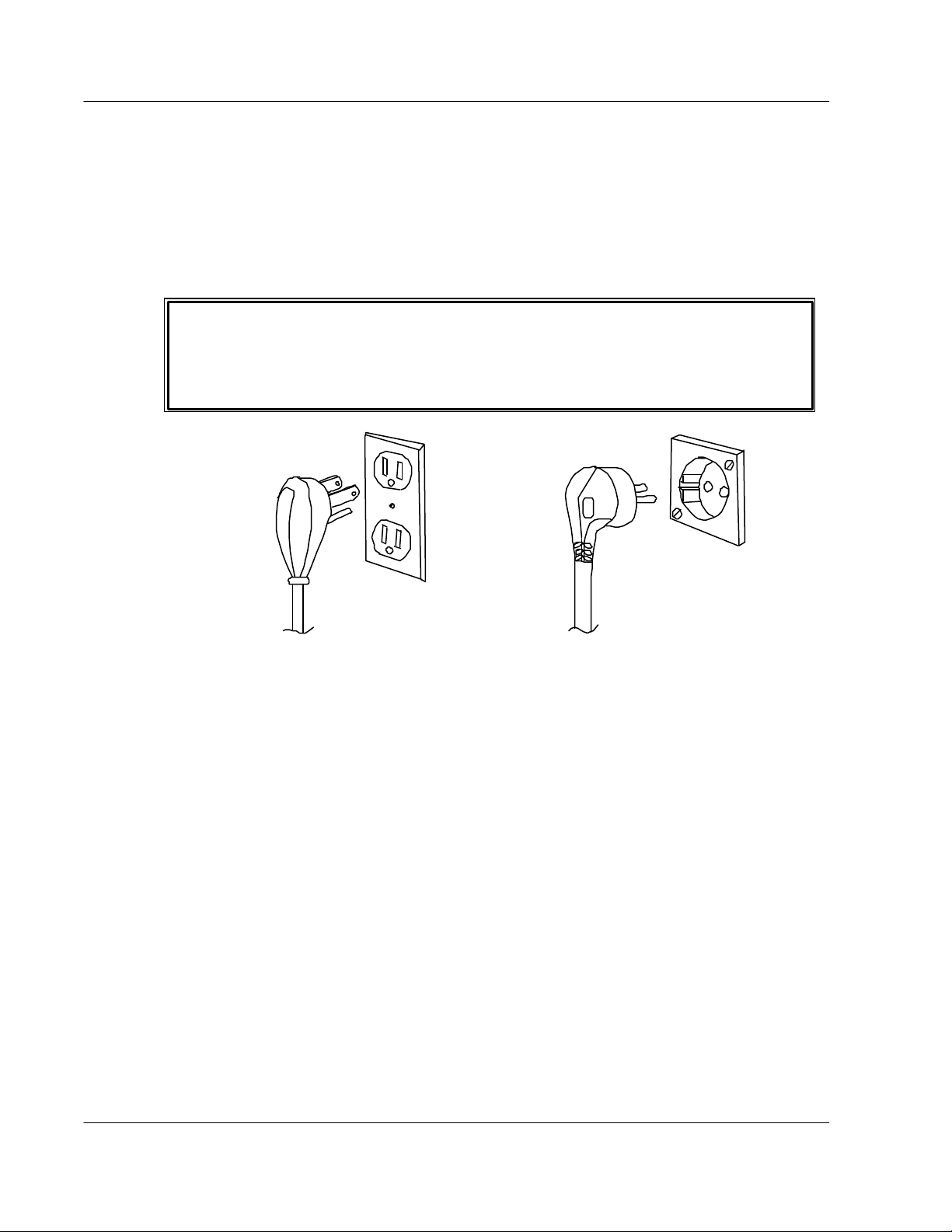
EElleeccttrriiccaall GGrroouunnddiinngg
An electrical ground is required and must be in place for this instrument.
Before installing the instrument, ensure that a grounded wall receptacle is available for each
unit. It must be plugged into a mating grounding type wall receptacle in accordance with
National Electrical Codes (US Domestic) and/or applicable local codes and ordinances
(domestic or international) for this type of installation. (Reference Figure 2, below)
UNDER NO CIRCUMSTANCES IS THE GROUND PRONG TO BE REMOVED. IF THE
GROUND PRONG, THE PL UG, OR THE CORD HAVE ANY PHYSICAL DAMAGE, THE CORD
IS TO BE REPLACED. IT IS EXTREMELY HAZARDOUS TO OPERATE THIS (OR ANY)
INSTRUMENT WITH A MISSING GROUND PRONG OR A FAULTY CABLE IN PLACE.
00..55..44
00..55..55
00..55..66
Fig. 2 - USA 115 VAC Standard Fig. 3 - European 230 VAC Standard
FFuussee RReeppllaacceemmeenntt WWaarrnniinngg
There are no user-serviceable fuses in the BacT/ALERT® 3D 60. Only trained and qualified
service technicians are to replace any fuse within the instrument. The only exception to fuse
installation will be during the initial installation of the unit. At the time of installation, the
customer does install PEM fuses according to steps outlined in the Installation section of the
BacT/ALERT 3D 60 Operator’s Manual.
HHaazzaarrddoouuss VVoollttaaggeess
DC voltages used within the instrument are low voltage and low current. They do not pose
any immediate hazard to technicians. There is, however, facility power of either 115 VAC or
230 VAC within or near the power supply assembly, which could pose an electrical hazard if
proper precautions are not observed. Note: All voltages are potentially hazardous under the
proper circumstances.
CClleeaanniinngg AAggeennttss
Follow manufactures’ instructions and MSDS (Material Safety Data Sheets) information to
prevent any possible hazards that may be present when using cleaning agents (or other
chemicals).
xxvi Service Manual
Page 31

BacT/ALERT® 3D 60 SAFETY SUMMARY
00..55
00..55..77
00..55..88
00..55..99
00..55..1100
SSAAFFEETTYY SSUUMMMMAARRYY ((CCOONNTTIINNUUEEDD))
HHeeaalltthh RRiisskkss
Specimens and inoculated culture bottles are to be assumed as though they are capable of
transmitting infectious agents. Handling of any bottles or spec imens must be done with the
utmost care. Spills must be cleaned as soon as possible, using the disinfection procedures
outlined in the BacT/ALERT® 3D 60 Operator’s Manual and Appendix C of this manual.
EESSDD PPrreeccaauuttiioonnss
The BacT/ALERT® 3D 60 contains several electrostatic sensitive devices within the modules.
Proper ESD precautions, in addition to the use of a grounding strap, are imperative whenever
working on or near any ESD components.
MMoovviinngg PPaarrttss
There are moving parts within the left side of the instrument’s chassis. At times, personnel
may be exposed to the Agitation Drive Arm, Motor Offset Round and other internal moving
parts. Care must be taken to avoid exposure of clothing, hands, fingers, arms, etc. Prior to
performing maintenance procedures around moving parts, it is advised that loose clothing
(i.e. ties, long sleeves, etc.) be secured.
HHeeaattiinngg EElleemmeenntt
The instrument contains a heater to perform the incubation process. The heater may remain
hot for a period of time after the unit is first shut down for maintenance. To prevent burns,
avoid contact with the heater until it is known that it is cool enough to touch.
Service Manual xxvii
Page 32

SAFETY SUMMARY BacT/ALERT® 3D 60
THIS PAGE
INTENTIONALLY
LEFT BLANK
xxviii Service Manual
Page 33

BacT/ALERT® 3D 60 CHAPTER 1 – GENERAL INFORMATION
CHAPTER 1
GENERAL INFORMATION
Page 34

CHAPTER 1 – GENERAL INFORMATION BacT/ALERT® 3D 60
THIS PAGE
INTENTIONALLY
LEFT BLANK
Service Manual
Page 35

BacT/ALERT® 3D 60 1 – GENERAL INFORMATION
11 GGEENNEERRAALL IINNFFOORRMMAATTIIOONN
This chapter describes the theory of operation and the general characteristics of the equipment.
11..11
IINNTTRROODDUUCCTTIIOONN
The following is a comprehensive list of the general descriptions of instrument components,
operational reference data, subassemblies and operator display configurations.
1 GENERAL INFORMATION ..............................................................................................1-1
1.1 INTRODUCTION...........................................................................................................1-1
1.2 REFERENCE DA TA.....................................................................................................1-2
1.3 EQUIPMENT DESCRIPTION.......................................................................................1-3
1.4 ASSEMBLY DESCRIPTIONS......................................................................................1-4
1.5 OPERATOR DISPLAY CONFIGURATION SCREENS............................................1-24
1.6 QUICK REFERENCE CARD ......................................................................................1-29
1-1
Page 36

1 – GENERAL INFORMATION BacT/ALERT® 3D 60
11..22
RREEFFEERREENNCCEE DDAATTAA
This chart represents the environmental conditions for use, including the physical, functional and
technical characteristics of the BacT/ALERT 3D 60 instrument.
Electrical Power
Service Required 100/120/220/240VAC @ 50/60Hz
Power Consumed
In Watts 120VAC: 480W Max
240VAC: 480W Max
Heat Dissipated
In BTU/hr 1639 BTU/Hr. Max
Equipment Characteristics
Width 23.1 in. / 58.7cm
Height 23.9 in./ 60.7cm
Depth 19.9 in. / 60.5 cm
Weight 94 lbs. / 42.5Kg
Environmental Characteristics
Operating Temperature Range 10°C - 30°C (50°F - 86°F)
Storage Temperature
Range 17°C - 57°C (0°F - 135°F)
Operating and Storage
Humidity Range 10% - 90% RH (non-condensing)
Operating and Storage
Altitude No restrictions
1-2 Service Manual
Table 1.2.1 – Combination Module Reference Data
Page 37

1 – GENERAL INFORMATION BacT/ALERT® 3D 60
11..33
EEQQUUIIPPMMEENNTT DDEESSCCRRIIPPTTIIOONN
The BacT/ALERT® 3D 60 instrument is a compact and automated microbial detection system
capable of incubating, agitating, and continuously monitoring specimens suspected of
contamination from bacteremia / fungemia.
The instrument consists of a WinSystems CPU and one 60 -bottle chamber consisting of three
racks of 20 culture bottles each. An externally attached display monitor permits the operator to
control and monitor the racks. (Refer to Figure 4, below)
Service Manual 1-3
Fig. 4 - BacT/ALERT 3D 60 Instrument
Page 38

DC Power
1 – GENERAL INFORMATION BacT/ALERT® 3D 60
11..44
11..44..11
AASSSSEEMMBBLLYY DDEESSCCRRIIPPTTIIOONNSS
The following paragraphs indicate the composition of the system, (i.e., the equipment, hardware,
software and consumables required for it to operate.
EElleeccttrriiccaall CCoommppoonneennttss
Fan
Supply
Fig. 5 - 3D 60 Power Panel Assembly Fig. 6 - Transformer
Relays
TB1
Transformer
Blower
Heater
Fig. 7 - Blower & Heater
1-4 Service Manual
Page 39

1 – GENERAL INFORMATION BacT/ALERT® 3D 60
11..44..11
EElleeccttrriiccaall CCoommppoonneennttss ((CCoonnttiinnuueedd))
1.4.1.1 Power Panel Assembly
The BacT/ALERT® 3D 60 instrument uses a standard BTA cabinet power supply. The
Power Panel Assembly provides the AC and DC power supply voltages that are used
within the 3D 60. With the use of relays, this will also shut down incubation processes
when instructed to do so by the ModSig PCBA. The power supply provides the four
separate DC voltages (+ 5V and ±12V) used throughout the instrument. (Refer to Figure
5)
1.4.1.2 Transformer Assembly
This is a transformer to isolate the instrument from facility power and is installed on the
System Power Panel. (Refer to Figure 6)
1.4.1.3 Heater
The heater provides the necessary heat for the incubation process of bottle cultures.
(Refer to Figure 7)
1.4.1.4 Blower
For the incubation process, the blower circulates heat (produced by the heater)
throughout the 3D 60 instrument. (Refer to Figure 7)
Service Manual 1-5
Page 40

1 – GENERAL INFORMATION BacT/ALERT® 3D 60
11..44..11
Step-5 Motor
EElleeccttrriiccaall CCoommppoonneennttss ((CCoonnttiinnuueedd))
Fig. 8 - Step-5 Motor Assembly Fig. 9 - Fan Assembly
Fan
1-6 Service Manual
Page 41

1 – GENERAL INFORMATION BacT/ALERT® 3D 60
11..44..11
EElleeccttrriiccaall CCoommppoonneennttss ((CCoonnttiinnuueedd))
1.4.1.5 Step-5 Motor Assembly
This Step-5 Motor (Figure 8) provides agitation to the racks, unless the incubation
chamber has been converted to MB and the motor has been disconnected to bypass
this process. (Refer to Subsection 4.4.2, Figures 59, 60 and 61 for MB Conversion)
1.4.1.6 Fan
A fan circulates air over the electronic components within the Electronics Compartment
to help prevent overheating. This fan may also be called the E-Fan. (Refer to Figure 9)
1.4.1.7 Quick Reference Card
This card identifies specific error codes and outlines instructions regarding system
operation. Refer to Section 1.6, Figure 31 - Front Side and Figure 32 - Rear Side)
Service Manual 1-7
Page 42

1 – GENERAL INFORMATION BacT/ALERT® 3D 60
11..44..22
CCoommmmuunniiccaattiioonnss PPoorrttss ((IInnppuutt // OOuuttppuutt))
Fig. 10 - BacT/ALERT 3D 60 System Control (Rear View) w/Comm Ports
1-8 Service Manual
Page 43

1 – GENERAL INFORMATION BacT/ALERT® 3D 60
11..44..22
CCoommmmuunniiccaattiioonnss PPoorrttss ((IInnppuutt // OOuuttppuutt)) ((CCoonnttiinnuueedd))
The communications ports are input/output ports that peripheral devices connect to on the
rear of the BacT/ALERT 3D 60 instrument. (Refer to Figure 10)
1.4.2.1 COMM Port
This port is reserved for future use.
1.4.2.2 Printer Port
A printer connects to this port via a parallel cable and produces hard copy reports.
1.4.2.3 Internal Speaker w/external Speaker Jack
The system has a remote speaker feature with a 5mm external mini-jack to drive two
remote stereo speakers from a distance of up to 450 feet (see Remote Speakers P/N
880-0002-01 and 02, along with 100-ft. of speaker wiring, P/N 957 -0004-350.
1.4.2.4 Power Entry Module (PEM) / ON-OFF Switch
The PEM contains the fuse protection for the unit when connected to main facility AC
power. The PEM also houses the main power switch for the instrument.
1.4.2.5 Modem Port
Used to connect the BacT 3D 60 to an external modem.
1.4.2.6 LIS Port
This port is used for connection to the facility’s LIS system.
1.4.2.7 Monitor Port
This port is used for connection to an external VGA or SVGA monitor.
1.4.2.8 UPS Port
Used to connect an external UPS to the instrument.
1.4.2.9 UPS Serial Port
Reserved for future use.
1.4.2.10 Mouse Port
Used for connecting the mouse to the instrument.
1.4.2.11 Keyboard Port
A port for connecting the keyboard to the instrument.
1.4.2.12 Barcode Scanner Port
Port for connecting the barcode -scanning wand to the instrument.
Service Manual 1-9
Page 44

1 – GENERAL INFORMATION BacT/ALERT® 3D 60
11..44..33
EElleeccttrroonniicc CCoommppoonneennttss
CPU Board ModSig Board
Fig. 11 - CPU PCBA Fig. 12 - ModSig PCBA
Quad Serial Board Thermistor Board
Fig. 13 - Quad Serial PCBA Fig. 14 - Thermistor PCBA
1-10 Service Manual
Page 45

1 – GENERAL INFORMATION BacT/ALERT® 3D 60
11..44..33
EElleeccttrroonniicc CCoommppoonneennttss ((CCoonnttiinnuueedd))
The Electronics Compartment is situated in the top part of the 3D 60 instrument. It contains
the internal WinSystems® computer (CPU PCBA and Quad Serial PCBA), CompactFlash
Adapter PCBA, Zip™ Drive, Step-5 PCBA and the ModSig PCBA.
1.4.3.1 CPU PCBA
The CPU is a 586 processor with an operating clock speed of 133MHz. This is the heart
of the system and controls all system operations. (Reference Figure 11)
1.4.3.2 ModSig PCBA
This board provides an interface between the CPU PCBA and the rest of the system. It
serves as a module controller for the system PCBAs, monitors incubation temperature
and the external port devices (i.e., modem, scanner, LIS, etc.) that are attached to the
3D 60 instrument. It also monitors several independent system tasks such as DC
voltages, switches, the frequency output of the speaker, power reset and other
functions. (Reference Figure 12)
1.4.3.3 Quad Serial PCBA
This board provides the communications interface from the WinSystems computer to
the rest of the system (incubator). (Reference Figure 13)
1.4.3.4 Thermistor PCBA (Input/Output)
There are two Thermistor PCBAs. One is the Input Thermistor and the other is the
Output Thermistor. The Input Sensor measures the air temperature from the warmer air
circulated by the heater fan and the Output Sensor the temperature of the cooler air
measured after Incubator Chamber circulation. A reading is taken from each sensor and
the average temperature reading of the two comprise the Incubator Chamber’s
temperature used by the temperature control logic. (Refer to Figure 14)
Note: The Input and Output Thermistors are not components of the Electronics
Compartment, yet they are described as integrated PCBAs of the electronic system.
The thermistors boards are installed in the lower compartment of the left and right inside
chassis, respectively.
Service Manual 1-11
Page 46

1 – GENERAL INFORMATION BacT/ALERT® 3D 60
11..44..33
NOTE: Flash memory disk above may not necessarily reflect the actual
memory disk or size being used in the 3D 60 instrument.
EElleeccttrroonniicc CCoommppoonneennttss ((CCoonnttiinnuueedd))
Fig. 15 - CompactFlash Memory Disk Fig. 16 - CompactFlash Adapter PCBA
1-12 Service Manual
Fig. 17 - Step-5 PCBA
Page 47

1 – GENERAL INFORMATION BacT/ALERT® 3D 60
11..44..33
EElleeccttrroonniicc CCoommppoonneennttss ((CCoonnttiinnuueedd))
1.4.3.5 CompactFlash Memo ry Disk
This CompactFlash disk is a removable mass storage device installed on the
CompactFlash Adapter PCBA. It is a device about the size of a matchbook and weighs
about one -half ounce. Since it is a solid-state device utilizing flash memory, it contains
no moving parts and requires no battery for data retention. The CompactFlash Disk is
compatible with IDE/ATAPI standards and serves as the C: drive in the BacT/ALERT 3D
60 application, where it holds the operating program, bottle records, system
configurations, event log files and miscellaneous other information needed for
BacT/ALERT operation. (Refer to Figure 15)
1.4.3.6 CompactFlash Adapter PCBA
The PCM-CFLASH PCBA (Reference Figure 16) is a PC/104 compatible adapter
module, designed specifically to adapt CompactFlash memory disks for use in
embedded systems such as the BacT/ALERT 3D 60. The adapter provides for
master/slave selection and a visual drive status indicator. The CompactFlash Adapter
PCBA is installed on the top cover of BacT/ALERT 3D 60 system.
1.4.3.7 Step-5 PCBA
The Step-5 controller board (Reference Figure 17) is designed to drive a five-phase
stepper motor at the speed of 60 revolutions per minute. The board operates with input
voltages of +5V and +12V, drives the stepper motor directly, and provi des starting and
stopping functions based on inputs received from the ModSig PCBA.
Service Manual 1-13
Page 48

1 – GENERAL INFORMATION BacT/ALERT® 3D 60
11..44..33
Fig. 18 - BacT 3D 60 Incubator Chamber Fig. 19 - Rack Assemb ly
EElleeccttrroonniicc CCoommppoonneennttss ((CCoonnttiinnuueedd))
1-14 Service Manual
Page 49

1 – GENERAL INFORMATION BacT/ALERT® 3D 60
11..44..33
EElleeccttrroonniicc CCoommppoonneennttss ((CCoonnttiinnuueedd))
1.4.3.8 Incubator Chamber Components
The Incubation Chamber (Reference Figure 18) contains three specimen racks, relays,
power supply, ModSig PCBA, rack controller PCB As, heater and blower. As viewed by
the operator, the bottles are loaded into the front of the 3D 60 instrument.
1.4.3.8.1 Rack
Each rack contains 20 bottle cells. Unless the instrument is designated as an MB
unit, the racks are continuously rocked (to provide agitation for the specimen
bottles). Also, three fascia plates identify the bottle locations and are not
interchangeable between replacement racks. (Refer to Figure 19)
1.4.3.8.2 Cell
There are 60 cells per instrument, with cells identified as 1 through 20 in the first
(top) rack, 21 through 40 in the middle rack and 41 through 60 in the bottom rack.
1.4.3.8.3 Cell Flag
The cell flag serves as a clip securing the bottles into their cells. The cell flag is
also a key component in bottle detection and cell diagnostics.
1.4.3.8.4 Cell Indicator Lamp
A lamp is located next to each cell and provides feedback to the operator.
Depending on the function selected by the operator, illuminated lamps identify the
positions of positive or negative bottles, cells that can be loaded, and so on. A
flashing indicator lamp indicates an operator error.
Service Manual 1-15
Page 50

NOTE
1 – GENERAL INFORMATION BacT/ALERT® 3D 60
11..44..44
Note: The figure above shows a flat panel monitor and
IInnppuutt // OOuuttppuutt DDeevviicceess
Fig. 20 - Operator Display Monitor Fig. 21 - Barcode Scanner
may not represent the model or type of monitor
actually shipped with the 3D 60 instrument.
Fig. 22 - Keyboard Fig. 23 - Zip Drive
The photos of output devices shown above may not necessarily reflect the models being installed.
1-16 Service Manual
Page 51

1 – GENERAL INFORMATION BacT/ALERT® 3D 60
11..44..44
IInnppuutt // OOuuttppuutt DDeevviicceess ((CCoonnttiinnuueedd))
1.4.4.1 Operator Display Monitor
The display monitor is a standard VGA monitor used for displaying diagnostic and
module setup information. (Reference Figure 20)
1.4.4.2 Barcode Scanner
The QuickScan™ 6000 Barcode Scanner scans bottle labels, identifying the bottles
whenever loading or unloading. (Reference Figure 21)
1.4.4.3 Keyboard
This is a standard-sized 101-key keyboard. It is used as an alternative input device to
the barcode scanner or mouse. (Reference Figure 22)
1.4.4.4 Zip Drive
This drive provides an internal resource for loading new operating system software and
performing system data backup. (Reference Figure 23)
Service Manual 1-17
Page 52

1 – GENERAL INFORMATION BacT/ALERT® 3D 60
THIS PAGE
INTENTIONALLY’
LEFT BLANK
1-18 Service Manual
Page 53

1 – GENERAL INFORMATION BacT/ALERT® 3D 60
11..44..44
IInnppuutt // OOuuttppuutt DDeevviicceess ((CCoonnttiinnuueedd))
1.4.4.5 56K FAX Modem (Domestic)
The fax modem serves as an interface to the BacT 3D 60 instrument for remote access.
The remote user is able to download and upload information, including seeing what is on
the display -screen that the local operator views. The Technical Support Center is able
to perform remote diagnostics and other troubleshooting of the instrument.
The modem interfaces the 3D 60 instrument through a connection to the Modem port on
the rear of the unit. Digital signals are converted to tones by the modem for sending to
the telephone system through the telephone jack connection and to a remote modem at
on the receiving end. Conversely, tones from the remote modem are converted to digital
signals and sent to the instrument through the Modem port. Power for the modem is
supplied by a wall-mounted power supply that supplies low voltage required by the
modem. The wall -mounted power supply plugs directly into a standard electrical outlet.
1.4.4.6 56K Fax Modem (International)
The international fax modem differs slightly from the domestic version, by having CE
markings and is shipped with a 220V AC adapter. It also has two additional DIPswitch
settings (9 & 10). (See Subsection 3.2.12, Figure 53, for instructions on International
Fax Modem DIP switch settings.
The fax modem serves as an interface to the BacT 3D 60 instrument for remote access.
The remote user is able to download and upload information, including seeing what is on
the display -screen that the local operator views. The Technical Support Center is able
to perform remote diagnostics and other troubleshooting of the instrument.
The modem interfaces the instrument through a connection to the Modem port on the
rear of the unit. Digital signals are converted to tones by the modem for sending to the
telephone system through the telephone jack connection and to a remote modem at on
the receiving end. Conversely, tones from the remote modem are converted to digital
signals and sent to the instrument through the Modem port. Power for the modem is
supplied by a wall-mounted power supply that supplies low voltage required by the
modem. The wall -mounted power supply plugs directly into a standard electrical outlet.
Service Manual 1-19
Page 54

Telephone Surge
Protection
120V Backup
Accessory Surge
Overload
1 – GENERAL INFORMATION BacT/ALERT® 3D 60
11..44..55
On/Off Switch
Test Switch
UUnniinntteerrrruuppttiibbllee PPoowweerr SSuuppppllyy ““UUPPSS””
Computer Interface Port
Protector
Receptacles
Receptacles
Fig. 24 - Uninterruptible Power Supply (UPS) Domestic Model – Front and Rear Views
1-20 Service Manual
Page 55

1 – GENERAL INFORMATION BacT/ALERT® 3D 60
11..44..55
UUnniinntteerrrruuppttiibbllee PPoowweerr SSuuppppllyy ““UUPPSS”” ((CCoonnttiinnuueedd))
Refer to Figure 24 for the following component descriptions of the domestic UPS.
1.4.5.1 On/Off Switch
Turns the UPS and BacT/ALERT 3D 60 unit ON and OFF from the UPS.
1.4.5.2 UPS Comm Port (Computer Interface Port)
The UPS Computer Interface Port is a standard 9-pin port used to connect a cable that
monitors communications between the UPS and the 3D 60 Instrument. (The port
connection is shown as Computer Interface Port in Figure 24)
1.4.5.3 Overload Reset Switch
The Overload Switch is a reset switch (breaker) allowing for UPS reset following a power
surge or uncommon UPS shutdown. The overload is rated 120VAC, 12 Amp (Max) at
50/60Hz.
1.4.5.4 Test (Check Battery/Alarm Disable) Switch
By pressing the top of Test (toggle) switch, the UPS battery may be checked. The UPS
powers the loads from the battery. If the UPS emits the battery exhaustion alarm, the
battery is weak and requires extended charge or replacement.
1.4.5.5 120V Backup Receptacles
These 120V AC receptacles are used when devices connected to the UPS require full
battery backup to allow proper shutdown of the equipment. A device that may require
such battery backup might be the Display Monitor, since it is required to shut down the
3D 60 instrument in a “facility power-fail” situation.
1.4.5.6 Accessory Surge Receptacles
These 120V receptacles are used when devices connected to the UPS do not require
battery backup but may require voltage surge protection. A device that may require
surge protection but not battery backup might be a Parallel Printer.
1.4.5.7 AC Power Cord
The AC Power Cord is a standard three-pronged AC (grounded) cord.
Service Manual 1-21
Page 56

Accessory Surge
240V Backup
Overload
Computer Interface
1 – GENERAL INFORMATION BacT/ALERT® 3D 60
11..44..55
UUnniinntteerrrruuppttiibbllee PPoowweerr SSuuppppllyy ““UUPPSS”” ((CCoonnttiinnuueedd))
On/Off Switch
Test Switch
Fig. 25 - Uninterruptible Power Supply (UPS) European Model – Front and Rear Views
P ort
Protector
Receptacle
Receptacles
1-22 Service Manual
Page 57

1 – GENERAL INFORMATION BacT/ALERT® 3D 60
11..44..55
UUnniinntteerrrruuppttiibbllee PPoowweerr SSuuppppllyy ““UUPPSS”” ((CCoonnttiinnuueedd))
The European UPS model is very similar to the US domestic model. The voltage rating,
power cord and fuse ratings, however, are for the European power conversions. (Refer to
Figure 25 for International/European UPS components)
Service Manual 1-23
Page 58

1 – GENERAL INFORMATION BacT/ALERT® 3D 60
11..55
OOPPEERRAATTOORR DDIISSPPLLAAYY CCOONNFFIIGGUURRAATTIIOONN SSCCRREEEENNSS
Fig. 26 - Instrument Configuration Screen
1-24 Service Manual
Page 59

Next Screen
1 – GENERAL INFORMATION BacT/ALERT® 3D 60
11..55
11..55..11
OOPPEERRAATTOORR DDIISSPPLLAAYY CCOONNFFIIGGUURRAATTIIOONN SSCCRREEEENNSS ((CCOONNTTIINNUUEEDD))
The BacT/ALERT 3D 60’s Operator’s Manual describes most of the screens displayed on the
display monitor. Specifically, it describes the screens used to: load/unload bottles, set the date
and time, enable/disable cells, calibrate incubation temperature, perform single cell calibration,
set maximum test times, set audible alarm options and change passwords. For detailed
information on these screens, refer to the BacT/ALERT 3D 60 Operator’s Manual.
IInnssttrruummeenntt CCoonnffiigguurraattiioonn SSccrreeeenn
This screen is primarily used when an instrument is being installed. It allows the field service
engineer to enter information regarding rack installation. (Refer to Figure 26)
1.5.1.1 Accessing the Configuration Screen
Perform the following steps to gain access to the Configuration Screen:
1. At the “Main Screen”, click on the [Next Screen] button (Refer to Figure 27, below)
button
2. Once at the “Setup Screen” (Refer to Figure 28), enter the Field Engineer password
<4><3><4><3><2><1><2><1>, by clicking on the number buttons at the top of the
screen. After entering the password, click on the [Key] button. (See “Setup Screen”
on the next page for Screen Diagnostics).
Fig. 27 - Main Screen
Service Manual 1-25
Page 60

Determines whether
Designates which
When checked, this
NOTE
required. “Hash marks” exist with
NOTE
Password Key
Configure Screen
1 – GENERAL INFORMATION BacT/ALERT® 3D 60
1.5.1.1 Accessing the Configuration Screen (Continued)
Key button
buttons
System Setup
Screen
button
Previous Screen button
Fig. 28 - Setup Screen w/Field Engineer Password Activation
Clicking on the [Configure Screen] button will access the “Configuration Screen”.
To get back to the Main Screen,
press the [Previous Screen] button.
1.5.1.2 Instrument Configuration Screen - Initial Entry
Use this screen to configure the instrument. (Refer to Figure 29, below.)
a period or comma,
this is used as a
decimal point.
Checks for enable/disabled racks
as well as rack configuration is
or without enable/disabled racks
or rack configuration.
Fig. 29 - Instrument Configuration Screen
racks are installed in
the 3D 60 instrument.
box designates the
unit as an MB unit.
1-26 Service Manual
Page 61

1 – GENERAL INFORMATION BacT/ALERT® 3D 60
1.5.1.3 Configuration Screen [X Box] Buttons
Several configuration options are represented by a graphical element called an [X Box]
button. As shown in Figure 30 below, an [X Box] button can appear with or without an
“X” in the box. The “X” determines the active selection. Clicking inside the box with the
mouse switches the box to the opposite state.
Fig. 30 - [X Box ] Selection Checkbox
Service Manual 1-27
Page 62

1 – GENERAL INFORMATION BacT/ALERT® 3D 60
THIS PAGE
INTENTIONALLY
LEFT BLANK
1-28 Service Manual
Page 63

1 – GENERAL INFORMATION BacT/ALERT® 3D 60
11..66
QQUUIICCKK RREEFFEERREENNCCEE CCAARRDD
The Quick Reference Card (Figure 31 and Figure 32 on the following pages, Front and Rear
Sides, respectively) is simply that…a quick reference. The card contains references to errors and
fault codes that may appear on the BacT/ALERT® 3D 60 during operation. The card’s purpose is
to aid the operator in determining what may have caused a particular problem. It does not
contain corrective action measures . For more information, refer to Appendix D – Error Codes of
this manual and the BacT/ALERT® 3D 60 Operator’s Manual for possible solutions.
Service Manual 1-29
Page 64

1 – GENERAL INFORMATION BacT/ALERT® 3D 60
11..66
QQUUIICCKK RREEFFEERREENNCCEE CCAARRDD ((CCOONNTTIINNUUEEDD))
Card P/N 955-0500-03 Rev A
OPERATION ERROR CODES
Refer to Operator Manual for detailed error description and troubleshooting instructions.
Code Description Code Description
901
902
910
911
912
942
913
921
923
CORRUPTED BOTTLE RECORD HAS BEEN SELECTED
REQUIRED DATA MISSING
INVALID CELL LOAD
INVALID CELL UNLOAD
INVALID CELL RELOAD
BOTTLE ID JUST SCANNED MATCHES THAT OF A
CURRENTLY LOADED BOTTLE
BARCODE SCAN NOT ALLOWED IN THIS MODE
INVALID BARCODE ENTRY
932
940
941
943
944
945
960
930
931
INCORRECT OR UNEXPECTED BARCODE SCANNED
AFTER UNLOADING A BOTTLE
DETECTION ALGORITHM HAS BEEN CHANGED
SEE REVERSE FOR INSTRUMENT FAULT CODES
961
BOTTLE ID SCANNED MATCHES THAT OF A PREVIOUSLY UNLOADED
BOTTLE
BOTTLE DETAIL NOT FOUND
BOTTLE ID ENTERED MATCHES THAT OF A BOTTLE THAT IS
CURRENTLY LOADED IN A DIFFERENT CELL
BOTTLE TYPE CHANGE REQUIRES DIFFERENT ALGORITHM
IDENTIFIED BOTTLE CHANGED TO ANONYMOUS
MANUAL UNLOAD OF ANONYMOUS BOTTLE
BOTTLE ID ENTERED MATCHES THAT OF A PREVIOUSLY UNLOADED
BOTTLE
DUPLICATE ENTRIES
INVALID BLANK FIELD
Fig. 31 - Quick Reference Card - Front Side
Detailed error descriptions and troubleshooting instructions may also be found in Appendix D of this manual.
1-30 Service Manual
Page 65

1 – GENERAL INFORMATION BacT/ALERT® 3D 60
11..66
QQUUIICCKK RREEFFEERREENNCCEE CCAARRDD ((CCOONNTTIINNUUEEDD))
INSTRUMENT FAULT AND STATUS CODES
Refer to Operator Manual for detailed error description and troubleshooting instructions.
Code Description Code Description
1
2
3
4
5
10
11
12
19
20
21
22
39
41-47
51-57
POWER FAULT IN INCUBATION MODULE
COMMUNICATION LOST WITH INCUBATION MODULE
INCUBATION MODULE TEMPERATURE IS TOO HIGH
INCUBATION MODULE TEMPERATURE IS TOO LOW
INCORRECT INCUBATION MODULE CONNECTION
CONTROLLER MODULE POWER FAULT
INSUFFICIENT CHARGE IN UPS
LIS COMMUNICATION FAULT
SOFTWARE EXCEPTION
DRAWER OPEN FOR TOO LONG
DRAWER AGITATION FAILURE
UNEXPECTED DRAWER AGITATION
RACK TEMPERATURE FAULT
RACK(S) NOT RESPONDING
RACK HARDWARE FAILURE
SEE REVERSE FOR OPERATOR ERROR CODES
60
62
71
72
73
74
75
77
78
79
99
710
800
810
CELL FAILED QC
ERRONEOUS CELL LOAD STATUS REPORTED
INVALID TIME STAMP
INVALID CALCULATION DATA
INVALID METHOD DATA
ALGORITHM CHANGE
BOTTLE DATA CORRUPTED
READING POLYNOMIAL CHANGE
INCOMPLETE TEST DATA
BOTTLE RELOADED VIA WRONG CONTROLLER
BOTTLE LOADED IN A NON-OPERATIONAL CELL
INCUBATION MODULE TEMPORARILY UNAVAILABLE WHILE POWER UP
INITIALIZATION TAKES PLACE
PRINTER FAULT
BACKUP FAILED
Fig. 32 - Quick Reference Card - Rear Side
Detailed error descriptions and troubleshooting instructions may also be found in Appendix D of this manual.
Service Manual 1-31
Page 66

1 – GENERAL INFORMATION BacT/ALERT® 3D 60
THIS PAGE
INTENTIONALLY
LEFT BLANK
1-32 Service Manual
Page 67

BacT/ALERT® 3D 60 CHAPTER 2 – BACKGROUND INFORMATION
CHAPTER 2
BACKGROUND INFORMATION
Service Manual
Page 68

CHAPTER 2 – BACKGROUND INFORMATION BacT/ALERT® 3D 60
THIS PAGE
INTENTIONALLY
LEFT BLANK
Service Manual
Page 69

BacT/ALERT® 3D 60 2 – BACKGROUND INFORMATION
22 BBAACCKKGGRROOUUNNDD IINNFFOORRMMAATTIIOONN
22..11
IINNTTRROODDUUCCTTIIOONN
The following is a comprehensive list of items outlined in this chapter. Included are the system
PCBAs and the function of each, as well as the Incubation Chamber and Power Supply.
2 BACKGROUND INFORMATI ON .................................................................................... 2-1
2.1 INTRODUCTION...........................................................................................................2-1
2.2 SYSTEM CONTROL - MODSIG PCBA .......................................................................2-2
2.3 THERMISTOR PCBA (INPUT/OUTPUT)....................................................................2-6
2.4 3D 60 POWER SUPPLY ASSEMBLY.........................................................................2-8
2.5 DC POWER SUPPLY.................................................................................................2-10
2.6 CPU PCBA.................................................................................................................2-12
2.7 COMPACTFLASH ADAPTER PCBA ........................................................................2-14
2.8 QUAD SERIAL INTERFACE PCBA..........................................................................2-16
2.9 RACK CONTROLLER PCBA....................................................................................2-18
2.10 STEP-5 PCBA............................................................................................................2-24
Service Manual 2-1
Page 70

2 – BACKGROUND INFORMATION BacT/ALERT® 3D 60
22..22
SSYYSSTTEEMM CCOONNTTRROOLL -- MMOODDSSIIGG PPCCBBAA
2-2 Service Manual
Fig. 33 - ModSig PCBA Diagram
Page 71

BacT/ALERT® 3D 60 2 – BACKGROUND INFORMATION
22..22
SSYYSSTTEEMM CCOONNTTRROOLL -- MMOODDSSIIGG PPCCBBAA ((CCOONNTTIINNUUEEDD))
The MODSIG PCBA provides interfaces to the 3D 60 Instrument Controller section, the Step-5
board, external peripherals and the Rack PCBA’s. It uses a 68HC11 microprocessor with
firmware stored in the EPROM. The microprocessor uses an external 16 MHz crystal for its
clock. 32Kbytes of EPROM and 32Kbytes of static RAM are external, with no internal ROM.
There are 512 bytes of EEPROM and 1024 bytes of RAM, both of which are internal.
A 4.5-volt reference is on the PCBA for A/D reference and a 2.5-volt reference for temperature
control. Power-fail circuitry detects if the +5VDC is out of tolerance. LED’s on the board show E
Fan ON, Power -Enable ON, Blower ON, Heater ON, Agitation ON, +5V ON for ModSig, +5V ON
for Step-5 PCBA, +5V ON for Racks, Door Switches Closed, six status indicators and RS -485
transmit and receive indicators.
Temperature sensors on the board are used for E-Fan control and to report electronics overtemperature conditions. External input and output temperature sensors are used by PID control
firmware on the microprocessor for incubation temperature control and are connected to JP1.
Heater, blower and fan ON/OFF time control signals connect through a connector at JP2. A 12bit, 8-channel A to D converter integrated circuit does conversion from analog values to digital
values for microprocessor use.
The front door has two separate interlock switches. These connect to the MODSIG PCBA
through JP11 and JP12. One switch, which the firmware cannot override, functions as a safety
interlock that disables the heater and blower if the door should open. The second switch is for
logic functions and redundancy. Both switches are monitored by the firmware and by the Step -5
agitation motor control firmware.
An instrument ID thumbwheel switch, normally set to 1, is available if there should be a need to
separately identify a 3D 60 at a customer’s site.
A Piezo buzzer is provided as an audible alarm. A remote speaker system may be used, by
connecting to J1. The keyboard connects to JP16. A barcode reader connects to P1 and a
mouse connects to P2. A parallel port printer connects to P4. A LIS system is interfaces via P8
and a modem via P9.
JP13, JP15, JP17, JP18 and JP19 connect to the Instrument Controller CPU in the 3D 60. JP29
and JP30 are used for transferring serial data signals from the Quad Serial PCBA. The Serial
UPS connec tor at P7 is for future use. The UPS is controlled through the connector at P5 and
must be connected for proper system operation. The VGA display monitor is connected at P6.
Five-volt power is connected to the board at JP31 and is supplied to the Zip Drive and the
CompactFlash PCBA through JP21. Control and data signals for the racks are supplied through
JP10.
Jumpers on the ModSig PCBA control the audio frequencies supplied to the remote speakers.
The remote speakers control volume. Volume jumpers on the board are for future use only. See
Table 2.2.1 for remote speaker audio frequency selections.
Service Manual 2-3
Page 72

2 – BACKGROUND INFORMATION BacT/ALERT® 3D 60
22..22
SSYYSSTTEEMM CCOONNTTRROOLL -- MMOODDSSIIGG PPCCBBAA ((CCOONNTTIINNUUEEDD))
FREQUENCY JP23 JP24 JP25 JP26
600 Hz In In In In
800 Hz In In In Out
1 KHz In In Out Out
1.5 KHz In Out Out Out
3 KHz Out Out Out Out
Table 2.2.1 - Audio Frequency Selection (JP23 through JP26)
2-4 Service Manual
Page 73

TO: Step-5 PCBA
JP1
Heater Inlet/Outlet
JP11
A/D
2 Temp
Instrument
Undervoltage/
• Blower ON
JP12
Door Interlock
Switches
JP13
JP15
JP17
JP18
JP29
JP30
JP31
JP19
Keyboard,
From CPU
Parallel I/O
RS-232,
RS-232 from
Quad Serial PCBA
Video from CPU
To & From
• Drawer ID
PS2 Keyboard
Barcode Port
Mouse Port
Parallel Printer
Port
UPS Control
VGA Monitor
+5V
Remote Speaker
Parallel I/O
To/From CPU
RS-232 from
BacT/ALERT® 3D 60 2 – BACKGROUND INFORMATION
22..22
Temperature
Sensors
SSYYSSTTEEMM CCOONNTTRROOLL -- MMOODDSSIIGG PPCCBBAA ((CCOONNTTIINNUUEEDD))
32KB RAM
68HC11
32KB RAM
Drivers
Converter
Overvoltage
Detector
Piezo Buzzer
Sensors
Oscillator
ID Switch
J2
JP2
JP10
JP16
P1
• Door Interlock
Switches
• +5 Power
• Agitate ON
FROM: Step- 5 PCBA
• Error Signal
• Heater ON
• Agitate ON
• E Fan ON
• Power En ON
Drawer A (#1)
Rack PCBA
• DC Power
• Rack ID
• Event Request
• RS-485
CPU
RS-232, Printer
To/From CPU
Rs-485 from
Quad Serial
+5VDC Power In
Driver
Fig. 34 - ModSig Block Diagram
Driver
P2
P4
P5
P6
JP21
J1
P7
P8
P9
CompactFlash
Zip Drive
Serial UPS
LIS
Modem
Service Manual 2-5
Page 74

J3
J2
J1
2 – BACKGROUND INFORMATION BacT/ALERT® 3D 60
22..33
TTHHEERRMMIISSTTOORR PPCCBBAA ((IINNPPUUTT//OOUUTTPPUUTT))
2-6 Service Manual
Fig. 35 - Thermistor PCBA
Page 75

BacT/ALERT® 3D 60 2 – BACKGROUND INFORMATION
22..33
TTHHEERRMMIISSTTOORR PPCCBBAA ((IINNPPUUTT//OOUUTTPPUUTT)) ((CCOONNTTIINNUUEEDD))
The Thermistor board uses an Analog device AD592BN temperature transducer to produce a
current flow proportional to temperature. The voltage source is +9VDC. The temperature
transducer has a nominal flow of 298.2µa+ 25ºC.
There are two Thermistors PCBAs in the 3D 60 instrument. The Input and Output Thermistors
measure input and output air temperature, respectively. The Input and Output temperature
readings are averaged together to comprise the Incubation Chamber’s temperature used by the
temperature control logic.
Service Manual 2-7
Page 76

Facility
Heater
Blower
Power
Enable
+12 VDC
E Fan
Elec.
2 – BACKGROUND INFORMATION BacT/ALERT® 3D 60
22..44
33DD 6600 PPOOWWEERR SSUUPPPPLLYY AASSSSEEMMBBLLYY
Power Distribution Block Diagram
Power
UPS
Power
Entry
Module
CPU PCBA
Isolation
Transformer
Common Logic Ground Return 3
+5 VDC
-12 VDC
MOV
TB 1
Blower
Heater
DC Power
Supply
Comp.
Fan
Relay
Relays
Relays
ModSig PCBA
Power Panel
+5VDC
Step Five PCBA
Agitation Motor
GND
Fig. 36 - Power Distribution Block Diagram
2-8 Service Manual
Page 77

BacT/ALERT® 3D 60 2 – BACKGROUND INFORMATION
22..44
33DD 6600 PPOOWWEERR SSUUPPPPLLYY AASSSSEEMMBBLLYY ((CCOONNTTIINNUUEEDD))
Input power for the 3D 60 (Refer to Figure 36) is either 115 VAC or 220 VAC. The installation
technician sets the proper voltage selection at the Power Entry Module (PEM). The circuitry is
protected by one 6.3A “time -delay” 250 VAC fuse (120 VAC version) or two 5A “time-delay” 250
VAC fuses (240 VAC version). AC voltage is coupled across the isolation transformer thus
insulating the instrument from facility power for circuit protection including a 120:120VAC or a
240:120VAC (step-down) voltage ratio.
Input power is routed to a metal oxide varistor (MOV) that’s mounted between terminals 2B & 3B
of TB1. The varistor provides inline surge protection for the internal circuitry of the system. From
TB1, power is routed to the fan, DC power supply and all “power-enable” relays.
The DC power supply provides the necessary DC voltages on J2 for various sub-units throughout
the 3D 60 Instrument. There are three separate voltages; ± 12VDC and + 5VDC, with a common
DC return providing a logic ground. In addition, the DC power supply provides a “Power Fail”
signal that is routed to the ModSig PCBA.
Service Manual 2-9
Page 78

2 – BACKGROUND INFORMATION BacT/ALERT® 3D 60
22..55
Input Voltage 85 - 264 VAC
Input Frequency Range 47 - 440 Hz
Input Surge Current Cold Start, 110 VAC/220 VAC 17 A maximum/ 34A maximum
Output Voltage Adjustability +5.1 VDC output (Supply Only)
DDCC PPOOWWEERR SSUUPPPPLLYY
Parameter Condition Limits
PIN CHART
P1 AC Ground
J1
J2
Table 2.5.1 - Power Supply Data
P2 AC Neutral
P3 AC Hot
P1 + 5.1 VDC
P2 + 5.1 VDC
P3 + 5.1 VDC
P4 Return
P5 Return
P6 Return
P7 Return
P8 + 12 VDC
P9 + 12 VDC
P10 PFD
P11 - 12 VDC
P12
P13 - 5 VDC
± 3%
2-10 Service Manual
Page 79

BacT/ALERT® 3D 60 2 – BACKGROUND INFORMATION
22..55
DDCC PPOOWWEERR SSUUPPPPLLYY ((CCOONNTTIINNUUEEDD))
The BacT/ALERT 3D 60’s power supply is a quad output switcher intended for small to mediumsized digital systems. These power supplies also contain built-in over-voltage protection and a
“power fail detect” signal.
Universal input voltage allows these supplies to be powered in any country of the world without
changing any jumpers or individual switch settings. The unit is capable of supplying the high
peak currents necessary to start disk drives and peripheral devices. An integral filter reduces
line-conducted noise below FCC and VDE limit B.
The over-voltage protection circuits are designed to activate at 6.25 VDC (± 0.75 VDC) for 5 VDC
output. The power supply has a “Power Fail Detection” circuit that produces a “power fail
detection” (PFD) output. The PFD signal occurs within milliseconds following an abnormal AC
line condition. The delay between the abnormal AC line condition and the PFD output varies
depending on AC line variation and power supply load.
If this condition is met, the PFD signal will go to a low state within approximately 3ms. Once the
output returns to the +4.75 VDC the PFD signal will return to a high state in 50ms to 200ms.
Refer to Table 2.5.1, on the previous page, for Power Supply data and output pin locations.
Service Manual 2-11
Page 80

+
R2
R3
U8
J8
U19
U20
+
U25
J37
J23
26
J30
U18
J14
J15
J16
J9
D1
J17
C8C7C6
J12
J13
J38
2 – BACKGROUND INFORMATION BacT/ALERT® 3D 60
22..66
CCPPUU PPCCBBAA
J4
J1
J2
C5
Y2 U7
J5 U11
T1
J
J28 J22
J3
C2
C1
U1
J21
U2
LITHIUM
KEEPER
II
LTC-3PN
U16
R1
R16 R5
R4
U3
C3 C4
U4
U14
J6
J10
U5
J21 J20
J24
J11
U9 U6
Y1
U15
J25
J41 U17
J31
U10
D2
J18
J27 J33
LS1
T2
J32
U21
J34
J40
C11
J35
U23
U27
U24
U29
U28
Y3
J36
D6 D5D4 D3
J39
+ + C9C10
U22
U26
SIM1
Fig. 37 - CPU PCBA Diagram
2-12 Service Manual
Page 81

BacT/ALERT® 3D 60 2 – BACKGROUND INFORMATION
22..66
CCPPUU PPCCBBAA ((CCOONNTTIINNUUEEDD))
The CPU PCBA (Reference Figure 37) is an “off-the-shelf” internally mounted WinSystems®
computer that combines a 586 (or higher) CPU with Video, Floppy, IDE, Serial and Digital I/O.
The chipset provides the core logic that makes the board PC/AT software compatible. It includes
the DRAM controller, bus interface, integrated peripheral controllers (8237 DMA, 82C54 timer,
82C59 PIC, RTC, KYBD controller and CMOS memory) and an internal PCI bus for high -speed
operation.
Up to 32 MB of memory can be populated on board with a 72 -pin SIMM. The BIOS can detect
and automatically support either Fast Page or EDO memory modules. Seven DMA channels are
supported, with Channel 2 dedicated to the floppy disk controller. The LPT is jumper selectable
for ECP operation. The other DMA channels are wired to the PC/104 connector. An onboard
256KB x 16 DRAM provides 512KB of video memory.
Service Manual 2-13
Page 82

2 – BACKGROUND INFORMATION BacT/ALERT® 3D 60
22..77
CCOOMMPPAACCTTFFLLAASSHH AADDAAPPTTEERR PPCCBBAA
Fig. 38 - CompactFlash Adapter PCBA
2-14 Service Manual
Page 83

BacT/ALERT® 3D 60 2 – BACKGROUND INFORMATION
22..77
CCOOMMPPAACCTTFFLLAASSHH AADDAAPPTTEERR PPCCBBAA ((CCOONNTTIINNUUEEDD))
A CompactFlash Adapter PCBA (with CompactFlash Memory Disk™ installed) is mounted near
the WinSystems® motherboard. It is connected by a flat ribbon cable to the motherboard’s IDE
port. (Refer to Figure 38 or Subsection 4.10.4, Figures 108-112)
The Flash-Memory Disk contains the operating system, BacT/ALERT® 3D 60’s software,
instrument configurations, operator settings, layout of the instrument pictorial, along with the
bottle record data.
Service Manual 2-15
Page 84

C7
R7
C5
J9
J10
C27 +
J12
2 – BACKGROUND INFORMATION BacT/ALERT® 3D 60
22..88
QQUUAADD SSEERRIIAALL IINNTTEERRFFAACCEE PPCCBBAA
R9
R1 R2
R10 R12
J3
U5
R11
1
U1
R36 R37
C1
RP1
U11
R5
R13
U9
C12
C13
J4
1
U12
R35
U2
J1
R6
R14
U7
Com 3 and Com 4, J3
1
R27
R28 R30
U18
1 1
R23 R24
J11
R29
U16
C26
C17 C18
C20 C21
U15
J7 J8
1
1
U3
C2
U6
C11
R22 R21 C8
C14
C3
RP2
U17
RP4
Copyright 1995 Made in USA
1
J2
R8
R15
R16
C9
C15
C23
C25
U13 R18 R20
U8
C19
C22
C24
RP3
R17
C10
U4
1
R31
R32
U10
J5
U14
C6
R3 R4
1
R38
R25 R26
1
C4
R19
J6
Com 1 and Com 2, J6
R34 R33
32
D C
WinSystems® PCM-COM4A Rev. B
Fig. 39 - Quad Serial Interface PCBA Diagram
2-16 Service Manual
Page 85

BacT/ALERT® 3D 60 2 – BACKGROUND INFORMATION
22..88
QQUUAADD SSEERRIIAALL IINNTTEERRFFAACCEE PPCCBBAA ((CCOONNTTIINNUUEEDD))
The Quad Serial Interface (Com4) board (Reference Figure 39) is a daughter board that plugs
into the PC/104 bus on the WinSystems® motherboard.
There are four ports on the board. Com 1 is configured as a RS -485 port. Com 2 3 and 4 are
configured as RS -232 ports. Com 1 and Com 2 are located on connector J6, while Com 3 and
Com 4 are located on connector J3. All communications ports are software supported and
operate at a 9.6K Baud data rate.
The Quad Serial is a four-channel serial (INS8250 compatible) P/C 104 module that is based on
the 16C554 UART. It is ideally suited for applications running DOS programs or languages that
require exact register compatible hardware for program execution. Each of the channels
supports RS-232, with optional RS-485 and RS-422 electrical levels to interface with a wide
variety of serial communications devices.
The Quad Serial PCBA is I/O mapped. Each channel requires eight port addresses and each is
independently decoded within the I/O map. The interrupt status register also requires one I/O
port. The addresses are decoded in the PAL and are jumper -selectable, with eight different I/O
maps. The Com4 card is a 16-bit stack-through card that supports 8-bit data transfers only.
Service Manual 2-17
Page 86

2 – BACKGROUND INFORMATION BacT/ALERT® 3D 60
22..99
RRAACCKK CCOONNTTRROOLLLLEERR PPCCBBAA
2-18 Service Manual
Fig. 40 - Rack Controller PCBA Diagram
Page 87

BacT/ALERT® 3D 60 2 – BACKGROUND INFORMATION
22..99
RRAACCKK CCOONNTTRROOLLLLEERR PPCCBBAA ((CCOONNTTIINNUUEEDD))
The Rack Controller PCBA (Refer to Figure 40), using EPROM-stored software, controls the
excitation LEDs. The LED light illuminates and reflects on the bottle sensors, creating emitted
measurable values at the photo detectors. The Rack Controller digitizes each cell’s photodetector output for reading by the ModSig’s Control Module and for bottle presence detection.
Cell indicator LEDs are controlled for operator information. Status and data are communicated
through an RS-485 cable from the Rack Controller to the ModSig board. The microprocessor
software also monitors the bottle rack rocking motion with a “Hall-Effect” sensor. In addition, the
software normalizes illumination readings with cell and temperature calibration factors. Address
lines from the ModSig are used to confirm that the 3D 60’s WinSystems® CPU board is
addressing the correct Rack Controller thus eliminating the need for switches on each Rack
Controller. Calibration values are stored onboard the Rack Controller PCBA in a non-volatile
RAM (NVRAM). The Rack Controller PCBA is located in the rear portion of the rack channel of
the Incubation Chamber. A fully implemented Incubation Chamber will have three Rack
Controller PCBAs.
The microprocessor is the Motorola 68HC11 and the same used on the ModSig PCBA. This
microprocessor has separate 16-bit address and 8-bit data lines defined. This eliminates the
need of having external address and data multiplexing for the external 32KB of RAM and 32KB of
EPROM included on the PCBA.
The clock speed of the 68HC11 is set at 16 MHz by an external crystal. Internally, the
microprocessor contains 512 bytes of EPROM, 1024 bytes of RAM, and no ROM. External
memory for the microprocessor is on the Rack Controller PCBA. A 16 -bit free running counter,
driven by a programmable prescaler and other divider chains, provides for a wide range of
internal timing periods for software use. Included is a watchdog timer.
The Rack Controller PCBA uses 32KB of static RAM in a surface mount package. The software
for most dynamic storage uses this memory. The Rack Controller uses 32KB of EPROM for
program storage. Jumpers are included to allow the installation of larger memory, in the event
that the 27C256 microprocessor becomes obsolete. Memory parts with less than 90ns access
are required.
There are two 20-pin connector positions on the board. Power (+5 volts for each board) is
supplied through a cable from the ModSig to the JP2 connector. The other connector, JP1, is
cabled to JP2 of the next rack. No other power is required. A fuse on the ModSig protects the
set of three Rack Controllers in the Incubator Chamber.
The +5 volt input voltage produces two reference voltages. A +4.5V reference is provided to the
A-D converter. A +2.5V reference is provided for the Rack temperature operational amplifiers as
well as an accurate current control of the exciter LED’s current by an operational amplifier.
Each cell has one exciter LED. Each of these LEDs is driven by an output from a 74ACT374
driver.
One indicator LED is provided for each bottle holder or cell. Each of the LEDs is driven by an
output from a 74ACT374 driver. In addition, there are four “status ” LEDs for general purpose and
are explained in the firmware.
Service Manual 2-19
Page 88

Sensors OP
Reference
previous Rack
2 – BACKGROUND INFORMATION BacT/ALERT® 3D 60
22..99
RRAACCKK CCOONNTTRROOLLLLEERR PPCCBBAA ((CCOONNTTIINNUUEEDD))
Rack Controller Block Diagram
Agitation
Sensor
Cell
Amps 1-20
Analog
Multiplexer
Rack
Temperature
Voltage
68HC11 Microprocessor
w/internal RAM and EPROM
12-Bit
A-D
Converter
Drivers
Constant
Current
Control
32 KB
RAM
32 KB
RAM
Cell
Exciters
1-20
Cell
Indicators
1-20
To/From
ModSig or
Controller
+5V IN
RS-485
Rack ID
Event Request
Rack ID OUT
Drawer ID
Drawer ID
Rack ID Output
Event Request
Fig. 41 - Rack Controller PCBA Block Diagram
RS-485
RCVR/XMTR
To/From Next
Rack Controller:
+5 V OUT
RS-485
Rack ID
Drawer ID
Event Request
Rack ID OUT
2-20 Service Manual
Page 89

BacT/ALERT® 3D 60 2 – BACKGROUND INFORMATION
22..99
RRAACCKK CCOONNTTRROOLLLLEERR PPCCBBAA ((CCOONNTTIINNUUEEDD))
Each cell has an individual external sensor. The sensor outputs are multiplexed to cascaded
operational amplifiers that drive the analog input of an A-D Converter. The cell sensor readings
are sent, on request, to the instrument. The Rack Controller firmware detects bottle presence
from these photodiode sensors as well.
Circuitry is provided to develop the analog signals to the A-D Converter for the two temperature
sensors on the Rack PCBA. These sensors are part of the calibration factors for the bottle cells.
The agitation sensor is a “Hall-Effect” sensor. The sensor detects bottle rack motion for a change
in magnetic flux from a rare-earth magnet as the rack is agitated. Each board has a sensor;
however, only one position in each drawer is utilized for monitoring.
The Event Request signal is a common open drain signal driven by the ModSig PCBA and all
Rack Controller PCBAs. The ModSig, Rack Controller and WinSystems CPU board can also
read the signal. Its purpose is similar to an interrupt signal; it's to notify the WinSystems CPU
board that an event such as a bottle removal has occurred. For the ModSig, this signal is both an
output to the WinSystems CPU board and an input from the Rack Controller. When the Event
Request is pulled low, the Drawer ID low signal used by the Rack Controllers is disabled. The
Rack Controller drives the Drawer ID lines to indicate which Rack Controller(s) activated the
Event Request line. The Rack Control firmware reads the Event Request line before and after
reconfirming its address, to ensure address lines are not in use.
With only one of four lines low for each drawer, the Rack Controllers can determine which drawer
they are in for each address identification for WinSystems CPU board commands. When the
Event Request is low, this is disabled; allowing the same lines to be used by the Rack Controllers
to identify which ones activated the Event Request. The driving circuitry and input circuitry is
provided on the Rack Controller. Firmware on the ModSig aids the WinSystems CPU board in
selecting which Rack Controllers read status, thus expediting bottle detection state changes.
The ModSig makes only one of the three Rack ID lines low for each rack, and then polling this
line within the Rack PCBAs, the Rack Controllers can determine their address without having
individual address switches. (Refer to Figure 42 on the next page)
Four outputs from one of the 74ACT374 -exciter LED drivers serve as the output drivers for the
Rack ID Out signals, through open-drain inverters.
The communication between the modules is over RS-485 full-duplex circuitry. The necessary
conversion between RS-485 differential signals and single-ended CMOS compatible serial
signals, for use by the software, is contained on the Rack Controller. The actual RS -485 signals
connect to all Rack Controllers through a connector on the ModSig PCBA.
Service Manual 2-21
Page 90

JP2 JP1
JP2 JP1
Polling line
2 – BACKGROUND INFORMATION BacT/ALERT® 3D 60
22..99
RRAACCKK CCOONNTTRROOLLLLEERR PPCCBBAA ((CCOONNTTIINNUUEEDD))
Rack Address Concept
JP10
ModSig
PCBA
+ 5V
+ 5V
16
17
18
connects via
JP2 on each
Rack PCBA
RACK #1
16 16
17 17
18 18
Rack #1 Address Code Rack #2 Address Code Rack #3 Address Code
Input pins 18-17-16 Input pins 18-17-16 Input pins 18-17-16
Binary 1- 1 - 0 Binary 1- 0- 1 Binary 0- 1- 1
RACK #2
16 16
17 17
18 18
Fig. 42 - Rack Address Concept
RACK #3
JP2 JP1
16 16
17 17
18 18
2-22 Service Manual
Page 91

BacT/ALERT® 3D 60 2 – BACKGROUND INFORMATION
22..99
RRAACCKK CCOONNTTRROOLLLLEERR PPCCBBAA ((CCOONNTTIINNUUEEDD))
A 12-bit A-D Converter is provided to convert the rack temperature sensor’s analog signals to the
digital signals used by the Rack Controller software. The same A-D Converter is used for
converting cell sensor analog signals into digital signals.
Using the +2.5V reference voltage, the resistor voltage dividers, an operational amplifier and a
MOSFET controls the current for the exciter LEDs. Only one exciter LED is activated at any one
time.
Service Manual 2-23
Page 92

2 – BACKGROUND INFORMATION BacT/ALERT® 3D 60
22..1100
SSTTEEPP--55 PPCCBBAA
2-24 Service Manual
Fig. 43 - Step-5 PCBA Diagram
Page 93

BacT/ALERT® 3D 60 2 – BACKGROUND INFORMATION
22..1100
SSTTEEPP--55 PPCCBBAA ((CCOONNTTIINNUUEEDD))
The Step-5 controller board (Reference Figure 43) is designed to drive a five-phase stepper
motor at the speed of 60 revolutions per minute. The board operates with input voltages of +5V
and +12V, drives the stepper motor directly, and provides starting and stopping functions based
on inputs received from the ModSig PCBA.
The STEP-5 controller board drives a Vextra 5-phase stepper motor at 1 revolution per second
(+10%) to provide rack agitation. The controller board’s inputs, outputs and features are listed
below.
1. Input (DC voltages): +5V and +12V
2. Input (Control)
• Interlocks: Two door switches are used. The two door switches are mechanical reed
switches that are closed when the door is closed. The STEP-5 uses optical isolators for
these inputs; when a switch is closed, current flows through the corresponding optical
isolator’s LED. If either switch is open, indicating a door open condition, motor rotation
stops. System design uses open switch position to indicate open door so that a
disconnected switch will also prevent motor operation. LED 55 & 56, are located on the
ModSig PCBA. The LED is on when a switch is closed.
• Start/Stop signal: The start/stop signal will go high to indicate that the STEP-5 should
run the agitation motor. This signal, generated by the ModSig PCBA goes high to enable
agitation. The input signal is optically isolated on the STEP-5.
• Position Sensor: A Hall -Effect sensor is located at the edge of the Step-5 board and
detects the magnet installed in the motor’s drive wheel. Both motor motion and drive
wheel position tracking is performed in the Step -5 board. Also, when the door is opened,
the sensor is used to determine how long to drive the motor so that the racks become
stationary in the correct position. If the position sensor is not functioning a fault output
will be generated. If the position sensor is not working, the STEP -5 will stop the motor
when the door is opened, but the position will be undefined.
3. Outputs:
A Fault Code is sent to the ModSig PCBA if certain conditions occur. The four conditions
that initiat e this code are:
• Motor over current
• Door switch (one door switch indicates open, the other indicates closed)
• Position sensor not changing state
• Safety timer not functioning (doesn’t go high after door opened)
(Also, See internal Output Codes)
Service Manual 2-25
Page 94

PHASE 1
2 – BACKGROUND INFORMATION BacT/ALERT® 3D 60
22..1100
SSTTEEPP--55 PPCCBBAA ((CCOONNTTIINNUUEEDD))
Motor Output: The PM589 motor is a 5-phase stepper, wired in a pentagon configuration,
500 steps per revolution in full step mode. Step sequence example for the 5 phases is:
If an over current occurs, the motor will be stopped. The fault signal is generated by the
open-collector of Q16, and goes LOW to indicate a fault. By design, a disconnected power
cable will also result in a fault indication.
4. Internal indicators:
• LED 1 Output Codes:
[1 flash]: Motor stopped OK
[2 flashes ]: Motor running OK
[3 flashes]: Motor over current
[4 flashes]: Door switch (one switch open, the other closed)
[5 flashes]: Position sensor not changing state
[6 flashes]: Safety timer not functioning (doesn’t go high after door opened)
[7 flas hes] Motor power bad (12VDC)
Note: LED 1 on the Step-5 PCBA constantly outputs one of the above codes. To interpret
the code, count the number of longer flashes (LED on periods) after the short start flash.
• Redundant door timer: The Step-5 includes a timer, independent of the microcontroller.
It disables the stepper motor after the door is opened and some delay has elapsed.
The redundant door timer consists of an oscillator clocking a pair of 14 -bit counters,
which are wired to result in a 28-bit binary divider. The counters are continuously reset
as long as both doors are closed. If either door interlock opens, the timers are allowed
to run. Either of two outputs from the high -order counter may be selected by installing a
zero-ohm resistor on the board. The selected output is applied to the PLD that drives
the low -side motor transistors. When the output goes high, the drive transistors are
disabled, regardless of the state of the microcontroller outputs.
The redundant timer is included to preclude the possibility that some undefined failure of
the microcontroller would leave the motor running after the door is open. The timer delay
is selected to insure that, under normal conditions, the microcontroller has time to stop
the motor normally before the delay expires. Once the delay expires, the PLD inhibits
the clock to the high-order counter to prevent the delay output from cycling. Delay
values are selected as described below (output selected is denoted as IC outputs are
labeled on schematic): The door timer output is monitored by the microcontroller, which
generates a fault output after some delay if the door is open and the timer output does
not go high.
PHASE 2
PHASE 3
PHASE 4
PHASE 5
2-26 Service Manual
Page 95

BacT/ALERT® 3D 60 2 – BACKGROUND INFORMATION
22..1100
SSTTEEPP--55 PPCCBBAA ((CCOONNTTIINNUUEEDD))
5. Motor voltage fault: If the motor supply voltage goes off, the microcontroller will turn off
motor drive until the motor supply is restored.
6. Power up protection: The high side predriver transistors require that the 16C74 source
current to turn them on. On power up, the I/O port pins of the 16C74 initialize inputs with no
pull-ups. This prevents cross-conduction between the high and low side MOSFETS. In
addition, as part of firmware initialization, the PLD that controls the low -side drivers does not
enable any outputs until PD7 is driven high.
7. Power down protection: The configuration bits for the 16F74 will enable the brownout
protection that resets the microcontroller if the supply drops below approximately 4V.
8. Crossover Protection: While running, the STEP -5 uses a stepping sequence that never
switches a motor phase from high to low or low to high. All motor phases go through a step
where the phase is off (neither the high or low side driver is on) between high and low
transitions. If this sequence is changed (for instance, if the board is ever used to drive a 4phase stepper), then crossover protection will need to be added to the firmware.
9. Temperature sensor: The printed circuit board and schematic provide for a temperature
sensor. This part is not installed in the current vers ion of the board.
10. Firmware: Firmware is developed in Microchip PIC assembly language. Firmware performs
the following functions:
• Debounce interlock switches
• Turn motor driver transistors on and off to generate motor drive waveform.
• Ramp motor up and down
• Control motor current during ramp up and ramp down using PWM duty cycle
• Track position of motor using position sensor as ‘home’ position
• Monitor motor current for over current condition
• Program microcontroller hardware to generate PWM clock
• When door open, monitor safety timeout circuit for proper operation
• Stop driving motor if 12V motor supply goes off
• Generate fault outputs
The firmware defines seven states for the stepper motor:
Stopped
Ramping up
Holding (constant speed)
Seeking (waiting for position count to reach ramp down point)
Ramping down
Fault (over current)
Motor power bad
Voltage is applied to the stepper motor using a Microchip PIC16C74 microcontroller and five pairs
of MOSFET transistors (5 ea. IRL520 and 5 each IRF9530).
Service Manual 2-27
Page 96

HIGH -SIDE
INTERLOCKS
2 – BACKGROUND INFORMATION BacT/ALERT® 3D 60
22..1100
SSTTEEPP--55 PPCCBBAA ((CCOONNTTIINNUUEEDD))
POSITION
SENSOR
STOP/RUN
COMMAND
(FROM
MODULE
CONTROLLER)
DC IN
INDEPENDENT
SAFETY TIMER
Microchip
PIC16C74
PLD
DRIVE
MOSFETS
PREDRIVERS
MOTOR
FAULT
OUTPUT
Fig. 44 - Step-5 PCBA Block Diagram
2-28 Service Manual
Page 97

BacT/ALERT® 3D 60 CHAPTER 3 – INSTALLATION PROCEDURES
CHAPTER 3
INSTALLATION PROCEDURES
Service Manual
Page 98

CHAPTER 3 – INSTALLATION PROCEDURES BacT/ALERT® 3D 60
THIS PAGE
INTENTIONALLY
LEFT BLANK
Service Manual
Page 99

BacT/ALERT® 3D 60 3 – INSTALLATION PROCEDURES
33 IINNSSTTAALLLLAATTIIOONN PPRROOCCEEDDUURREESS
33..11
IINNTTRROODDUUCCTTIIOONN
This paragraph presents the Installation Procedures chapter contents.
3 INSTALLATION PROCEDU RES.................................................................................... 3-1
3.1 INTRODUCTION...........................................................................................................3-1
3.2 BACT/ALERT 3D 60 INS TALLATION PROCEDURES..............................................3-3
3.3 RESTRAINT INSTALLATI ON....................................................................................3-14
3.4 SOFTWARE INSTALLATION....................................................................................3-17
3.5 SWITCHING ON.........................................................................................................3-17
Service Manual 3-1
Page 100

3 – INSTALLATION PROCEDURES BacT/ALERT® 3D 60
THIS PAGE
INTENTIONALLY
LEFT BLANK
3-2 Service Manual
 Loading...