

Page 1

Triton2
Operator Manual
ENGLISH
www.bandg.com
Page 2

Page 3

Preface
Disclaimer
As Navico is continuously improving this product, we retain the
right to make changes to the product at any time which may not be
reflected in this version of the manual. Please contact your nearest
distributor if you require any further assistance.
It is the owner’s sole responsibility to install and use the equipment
in a manner that will not cause accidents, personal injury or
property damage. The user of this product is solely responsible for
observing safe boating practices.
NAVICO HOLDING AS AND ITS SUBSIDIARIES, BRANCHES AND
AFFILIATES DISCLAIM ALL LIABILITY FOR ANY USE OF THIS PRODUCT
IN A WAY THAT MAY CAUSE ACCIDENTS, DAMAGE OR THAT MAY
VIOLATE THE LAW.
Governing Language: This statement, any instruction manuals, user
guides and other information relating to the product
(Documentation) may be translated to, or has been translated from,
another language (Translation). In the event of any conflict between
any Translation of the Documentation, the English language version
of the Documentation will be the official version of the
Documentation.
This manual represents the product as at the time of printing.
Navico Holding AS and its subsidiaries, branches and affiliates
reserve the right to make changes to specifications without notice.
Trademarks
NMEA® and NMEA 2000® are registered trademarks of the National
Marine Electronics Association.
Copyright
Copyright © 2016 Navico Holding AS.
Warranty
The warranty card is supplied as a separate document.
In case of any queries, refer to the brand website of your display or
system: www.bandg.com.
Preface | Triton2 Operator manual
3
Page 4
Compliance statements
This equipment complies with:
• CE under EMC directive 2014/30/EU
• The requirements of level 2 devices of the Radio communications
(Electromagnetic Compatibility) standard 2008
The relevant Declaration of conformity is available in the product's
section at the following website: www.bandg.com.
About this manual
This manual is a reference guide for operating the Triton2. It
assumes that all equipment is installed and configured, and that the
system is ready to use.
The manual assumes that the user has basic knowledge of
navigation, nautical terminology and practices.
Important text that requires special attention from the reader is
emphasized as follows:
Note: Used to draw the reader’s attention to a comment or
Ú
some important information.
Warning: Used when it is necessary to warn
personnel that they should proceed carefully to
prevent risk of injury and/or damage to equipment/
personnel.
Manual version
This manual is written for software version 1.0. The manual is
continually updated to match new software releases. The latest
available manual version can be downloaded from
www.bandg.com.
4
Preface | Triton2 Operator manual
Page 5

Contents
7 Introduction
7 Manuals
8 Front panel and keys
9 Basic operation
9 Turning the unit on and off
9 Operating the menu system
10 Display setup
11 Display mode
12 Selecting a data page
13 Man Over Board (MOB)
15 Pages
15 Enabling/disabling a page
15 Automatic scrolling pages
16 Predefined pages and template pages
25 Configuring data pages
27 Missing or faulty data
28 Race timer and Trip log
28 Race timer
29 Trip log
31 AIS
31 The AIS page
31 AIS target symbols
32 Selecting a target
32 AIS page display options
33 Displaying target information
33 AIS messages
34 AIS SART
34 Vessel alarms
36 AIS settings
38 Autopilot
38 Safe operation with the autopilot
39 Autopilot controller
Contents | Triton2 Operator manual
5
Page 6

40 The autopilot page
40 Autopilot modes
47 Using the autopilot in an EVC system
47 Autopilot alarms
47 Autopilot settings
57 Alarms
57 Alarm indication
57 Acknowledging the alarms
58 Enabling the alarm system and the alarm siren
58 Alarm history
59 Alarm limits on analog pages
60 Software setup
60 Remote displays
61 Calibration
69 Damping
69 System settings
75 Maintenance
75 Preventive maintenance
75 Cleaning the display unit
75 Checking the connectors
75 Software update
78 Menu flow chart
78 Page menus
78 Settings menu
82 Technical specification
83 Dimensional drawing
84 Terms and abbreviations
86 Supported data
86 NMEA 2000 PGN (transmit)
86 NMEA 2000 PGN (receive)
6
Contents | Triton2 Operator manual
Page 7

1
Introduction
The Triton2 is a networked multifunction instrument. The display
shows data measured by sensors and other equipment connected
to the system.
The unit calculates speed, wind, trip distance and time, average
speed, set and drift. A race timer is also included.
If a compatible autopilot computer is connected to the network, the
Triton2 will also display autopilot status.
The autopilot can be controlled by the optional Triton2 Pilot
controller. The Triton2 can then be used as the autopilot display, and
full autopilot functionality will be available.
Manuals
The following documentation is available for the Triton2 system:
•
Triton2 Operator manual (988-11214-00n) - this manual
•
Triton2 Quick guide (988-11219-00n)
•
Triton2 Pilot controller User Guide (988-11224-00n)
•
AP44/IS42/Triton2 Installation guide (988-11229-00n)
•
AP44/IS42/Triton2 Mounting template (988-11230-00n)
•
OP12/Triton2 Autopilot controller Mounting template
(988-11231-00n)
• H5000 Installation manual (988-10635-00n)
• NAC-2/NAC-3 Autopilot computer Commissioning manual
(988-11233-00n)
• AC12N/AC42N Installation manual (988-10276-00n)
Note: The last digit in the part numbers is the document's
Ú
revision code. The latest version of all documents can be
downloaded from the product website on www.bandg.com.
Introduction | Triton2 Operator manual
7
Page 8

Front panel and keys
1 2 3 2 4
1 Pages key
With no menu active:
• Press to scroll through the enabled data pages
• Press and hold to display a list of enabled pages from
where you can select directly the page to display
Menu and dialog operation: Press to return to previous
menu level or to exit a dialog.
2 Arrow keys
Press to move up and down in menus and dialogs.
Press to adjust a value.
3 Enter key
Press to select a menu option and to enter the next menu
level.
Press to activate/deactivate a menu/dialog option.
4 MENU/Backlight key
Press once to display the page menu.
Double-press to display the Settings menu.
Press and hold to display the Display setup dialog from
where you can adjust the display backlight.
8
Introduction | Triton2 Operator manual
Page 9
2
Basic operation
Turning the unit on and off
The unit has no power key, and it will be running as long as power is
connected to the NMEA 2000 network backbone.
First time startup
When the unit is started for the first time and after a factory reset,
the unit displays a setup wizard. Respond to the setup wizard
prompts to select some fundamental setup options. These settings
can later be changed and further configuration made as described
in "Software setup" on page 60.
Sleep mode
In Sleep mode, the backlight for screen and keys are turned off to
save power. The system continues to run in the background.
You select Sleep mode from the Display setup dialog, activated by
pressing and holding the MENU key. Switch from Sleep mode to
normal operation by a short press on the MENU key.
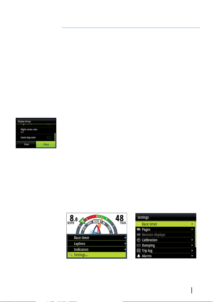
Operating the menu system
All functions and settings in the unit are available from the menu
system, activated by pressing the MENU key from any page.
Not all pages have a page specific menu, but all page menus give
access to the Race timer and to the Settings menu.
You can also access the Settings menu by double-pressing the
MENU key.
Page menu
Basic operation | Triton2 Operator manual
Settings menu
9
Page 10
• Use the arrow keys to move up and down in the menus and in
the dialogs
• Confirm a selection by pressing the Enter key
• Return to previous menu level by pressing the Pages key
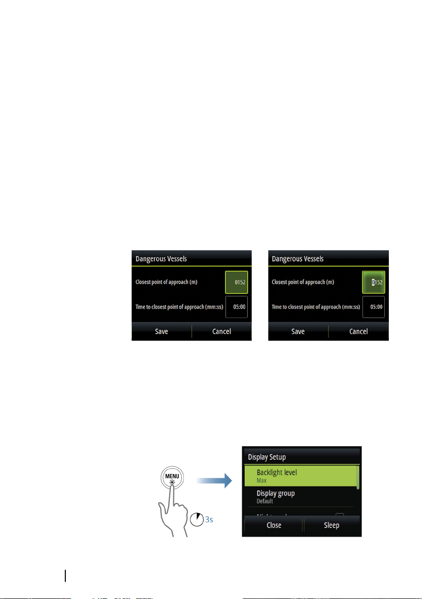
Edit a numeric value
1. Use the arrow keys to select the entry field
2. Press the Enter key to turn the field into edit mode
- The left digit starts flashing
3. Use the arrow keys to set the value for the flashing digit
4. Press the Enter key to move focus to the next digit
5. Repeat step 3 and 4 until all digits are set
6. Press the Enter key to leave edit mode for the selected field
7. Use the arrow keys to select the Cancel or Save buttons, then
press the Enter key to confirm your selection and to close the
dialog
10
Selected field
Note: You can at any time press the Pages key to leave a dialog
Ú
without saving the entries.
Field in edit mode
Display setup
Basic operation | Triton2 Operator manual
Page 11
The display setup can be adjusted at any time from the Display
setup dialog, activated by pressing and holding the MENU key.
The following options are available:
• Backlight level: Adjusts the backlight level from Min (10%) to Max
(100%) in 10% increments
- When the Backlight level field is active, subsequent presses on
the MENU key adjusts backlight level in decrements of 30%
• Display group: Defines which network group the unit belongs to
• Night mode: Activates/deactivates the night mode color palette
• Night mode color: Sets the night mode color palette
• Invert day color: Changes the background color for the pages
from default white to black
• Sleep: Turns the backlight for screen and keys off to save power
Note: All changes made to the display setup will apply to all
Ú
units belonging to the same display group. For more
information about network groups, refer to "Network groups" on
page 72.
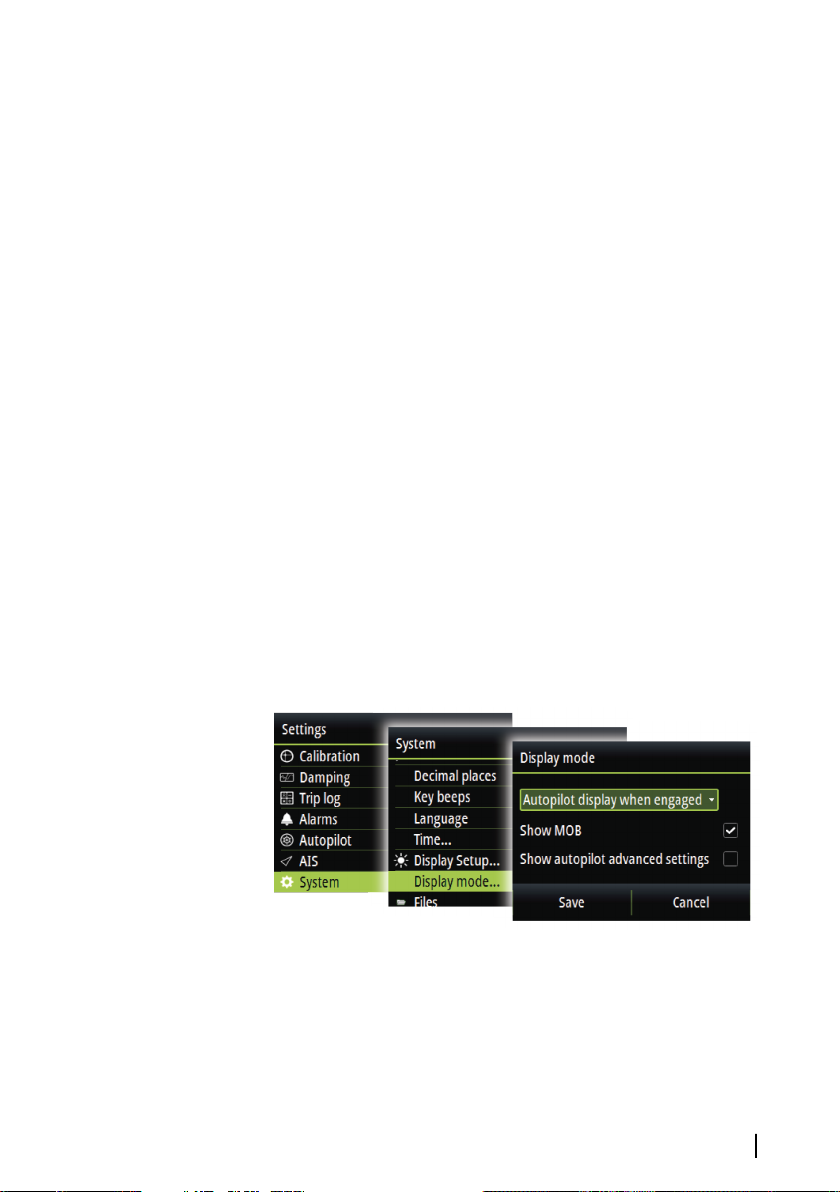
Display mode
The Triton2 unit can be set up as an instrument only, as an autopilot
display only, or as a combination of those two display modes.
• Instrument display only: Displays active data pages. The Autopilot
page can be one of these data pages
• Autopilot display only: Displays only the autopilot page
Basic operation | Triton2 Operator manual
11
Page 12
• Autopilot display when engaged: Switches automatically to the
Autopilot page when the autopilot is switched to an automatic
mode. When the autopilot is switched to Standby mode the
display switches back to the previous page. This behaviour does
not require that an Autopilot page is selected as one of the 8
enabled data pages
The Display mode dialog has the following additional options:
• Show MOB: Switches automatically to the MOB page if a Man
Over Board event is triggered from another system on the
network. Refer to "Man Over Board (MOB)" on page 13
• Show autopilot advanced settings: Displays all available autopilot
settings. Refer to "Sailing (H5000)" on page 50.
Selecting a data page
The Triton2 includes 16 predefined data pages, but only 8 of these
can be enabled.
For detailed information about pages, refer to "Pages" on page 15.
Two options are available for selecting an enabled page:
• Directly selecting a page
• Scrolling pages
For automatic page scrolling, refer to "Automatic scrolling pages" on page
15.
12
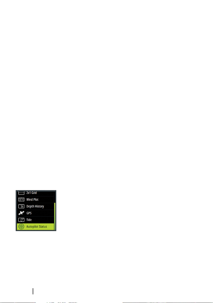
Directly selecting a page
Press and hold the Pages key to display a list of enabled pages, then:
• use the arrow keys to select the page you want to display
• confirm your selection by pressing the Enter key
If you don't confirm your selection the menu will timeout and the
highlighted page will be displayed after 3 seconds.
Scrolling through enabled data pages
Press the Pages key to scroll through the enabled data pages.
Basic operation | Triton2 Operator manual
Page 13
Man Over Board (MOB)
Note: MOB and AIS-SART will only work with a B&G
Ú
Multifunction Display (MFD) on the network.
If a Man Over Board event is triggered from another system on the
network, the instrument automatically switches to the MOB page.
This function can be enabled/disabled from the Display setup
dialog. Refer to "Display mode" on page 11.
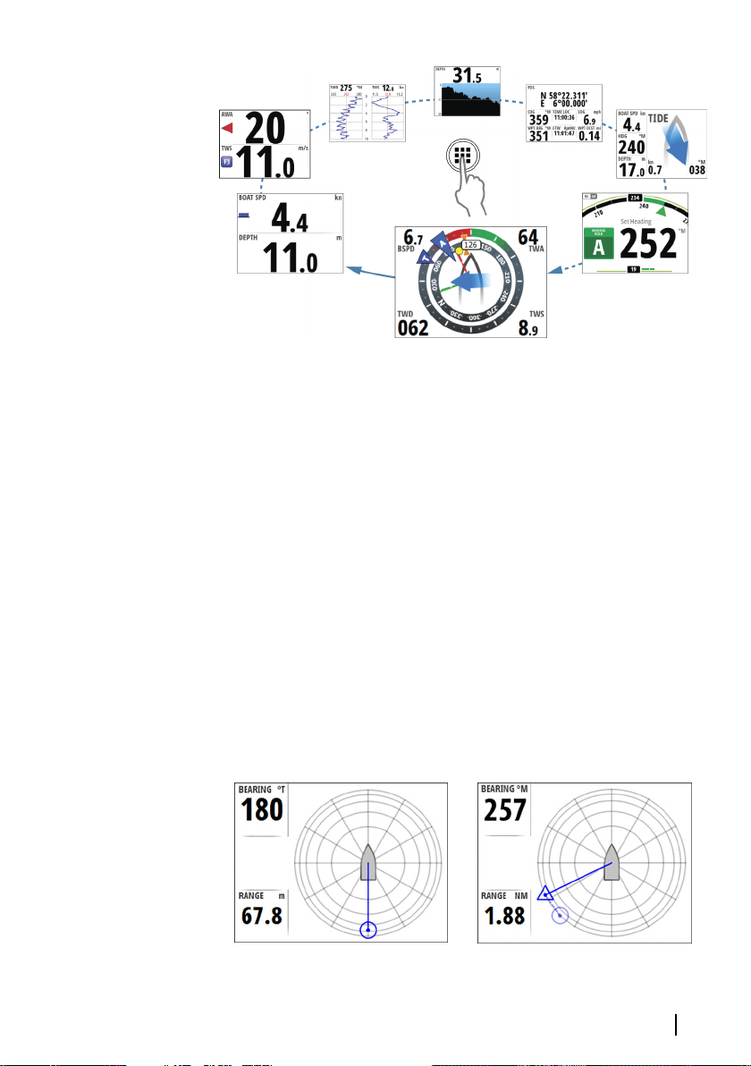
The MOB page shows the position, the range and the bearing of the
MOB at the position the MOB function was activated. If the man
over board event is activated via an AIS-SART, the MOB position is
updated via the AIS-SART signal.
Note: If you have an H5000 CPU on the network the CPU will
Ú
perform dead reckoning calculations to provide the estimated
position of the man over board. This estimated position will be
displayed as a triangle symbol.
Received MOB position
Basic operation | Triton2 Operator manual
Received and estimated MOB positions
13
Page 14

The system continues to display navigational information towards
the MOB waypoint until you cancel the navigation from the menu.
14
Basic operation | Triton2 Operator manual
Page 15
3
Pages
The Triton2 includes 16 predefined data pages.
In addition to these pages there are 13 template pages that can be
used for creating user defined pages.
You can have up to 8 pages enabled in the unit. These can be any
combination of predefined pages and user defined pages.
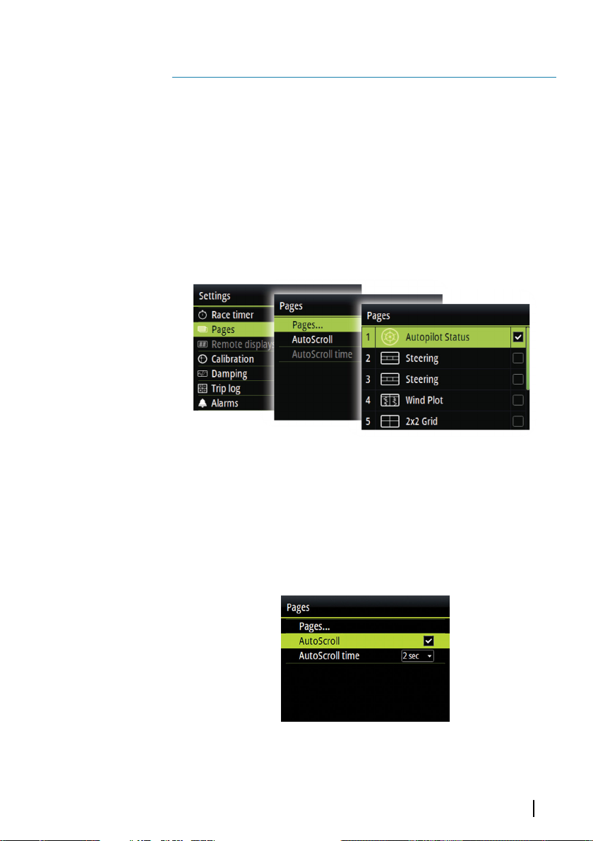
Enabling/disabling a page
To make a page available via the Page key you need to ensure it has
been selected as one of the eight enabled pages.
Automatic scrolling pages
You can select to let the system automatically scroll through all
enabled pages at a defined time interval.
You set the time interval and start the automatic scrolling function
from the Pages menu.
Pages | Triton2 Operator manual
15
Page 16
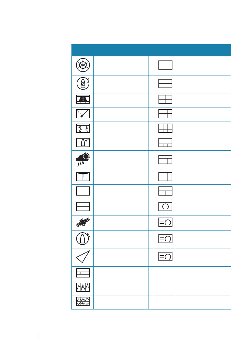
Predefined pages and template pages
000.0
ft
Pre-defined pages Template pages
Autopilot status
Sailsteer 2x1 Grid
Highway 2x2 Grid
Laylines 2x2 Grid Offset
Wind plot 3x3 Grid
Tide 1 + 3 Digital - bottom
Weather 1 + 6 Digital
Depth history 1 + 3 Digital - side
Basic Speed & Depth 1 + 4 Digital
Basic Wind angle &
Speed
GPS Analog + 3
Full screen
Single analog
Composite wind Composite Wind + 3
AIS SailSteer + 3
Steering
Single Time plot
Dual Time plot
16
Pages | Triton2 Operator manual
Page 17
Autopilot status page
Autopilot status. Refer to "Autopilot" on page 38.
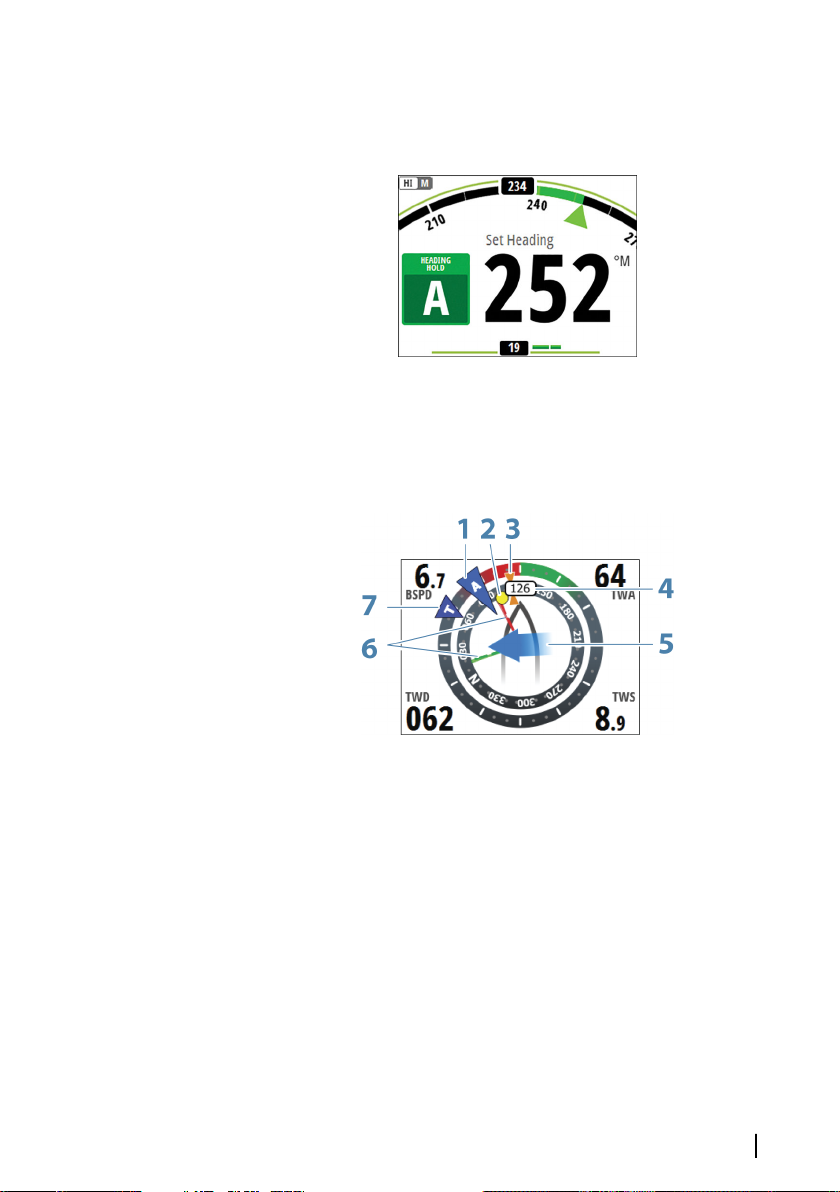
SailSteer page
Core Sailing data displaying all key data relative to the yacht's bow
for easy visualization.
1 Apparent wind *
2 Bearing to current waypoint *
3 COG (Course Over Ground) *
4 Vessel heading
5 Tide rate and relative direction *
6 Port (red) and Starboard (green) Laylines *
7 TWA (True Wind Angle) - Green if on TWA upwind or
downwind. Blue if off target by 10º or more, or on a free leg.
The indicator will fade from blue to green the closer you get
to the exact angle
Pages | Triton2 Operator manual
17
Page 18
* Optional page items.
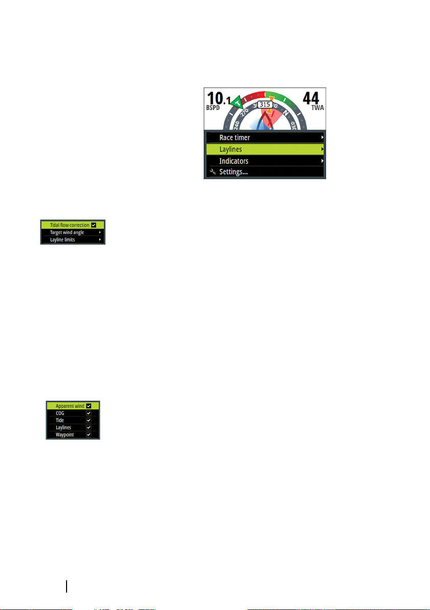
The following options are available from the menu for configuring
the SailSteer page:
Laylines
• Tidal flow correction: Calculates the tidal flow and offsets the
laylines accordingly
• Target wind angle: Used for selecting the available target wind
angle options:
- Polar: Takes the target wind angle from the active polar table
- Actual: Takes the instantaneous wind angle
- Manual: Used for manually entering the upwind and
downwind values
• Layline limits: Shaded areas indicating the minimum and
maximum tack/gybe time period to either side of the layline. This
can be set to 5, 10, 15 or 30 minute increments.
18
Indicators
Defines which indicators are displayed on the SailSteer page.
Pages | Triton2 Operator manual
Page 19
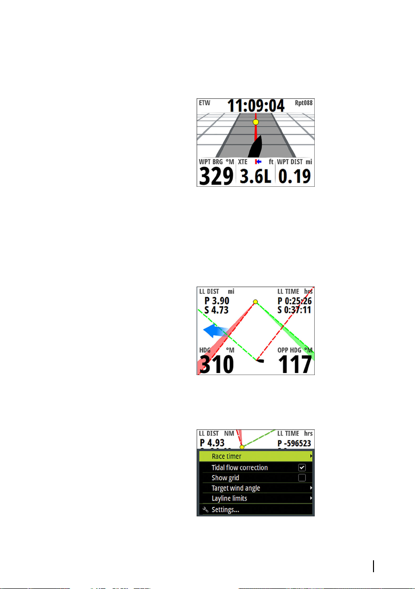
Highway page
Navigation information, including a 3D view of the boat position on
the track.
Laylines page
Note: The Laylines page is only available when an H5000 CPU is
Ú
connected to the system.
Laylines to mark/waypoint with limits.
The following options are available from the menu for configuring
the page:
Pages | Triton2 Operator manual
19
Page 20
Tidal flow correction
Calculates the tidal flow and offsets the laylines accordingly.
Show grid
Shows a grid with each square representing one boat length.
Target wind angle
True wind angle is used in the layline calculations. There are 3
options available:
• Polar: Takes the target wind angle from your polar table in the
H5000 CPU
• Actual: Takes the current value of target wind angle
• Manual: Allows for manually entering upwind and downwind
values
Layline limits
When selected will show a shaded area indicating the minimum
and maximum tack/gybe time period either side of the layline. This
can be set to 5, 10, 15 & 30 minute increments.
20
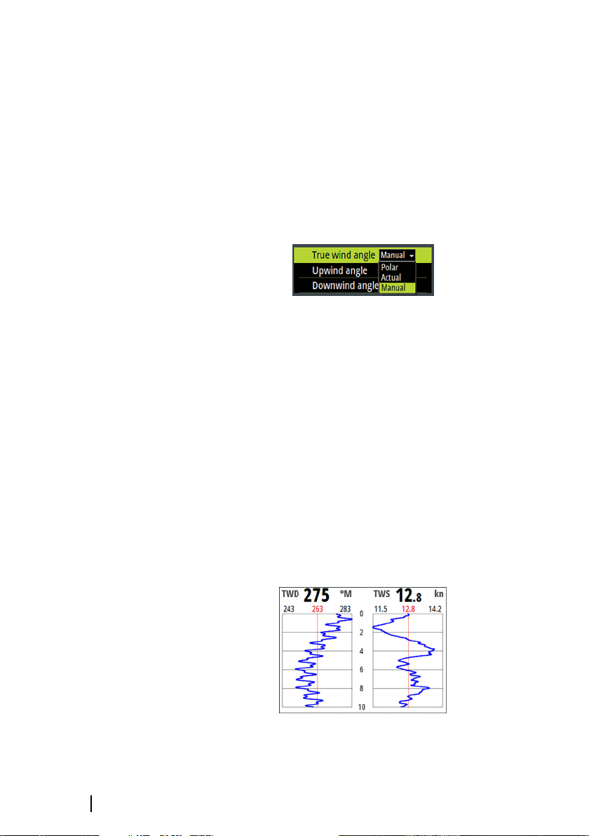
Wind Plot
True wind direction (TWD) and true wind speed (TWS) as a plotted
graph over a specified timescale.
Pages | Triton2 Operator manual
Page 21
The Wind histogram time period can be set to show 5, 10, 30 or a 60
minutes history.
You change the period from the menu or by using the arrow keys.
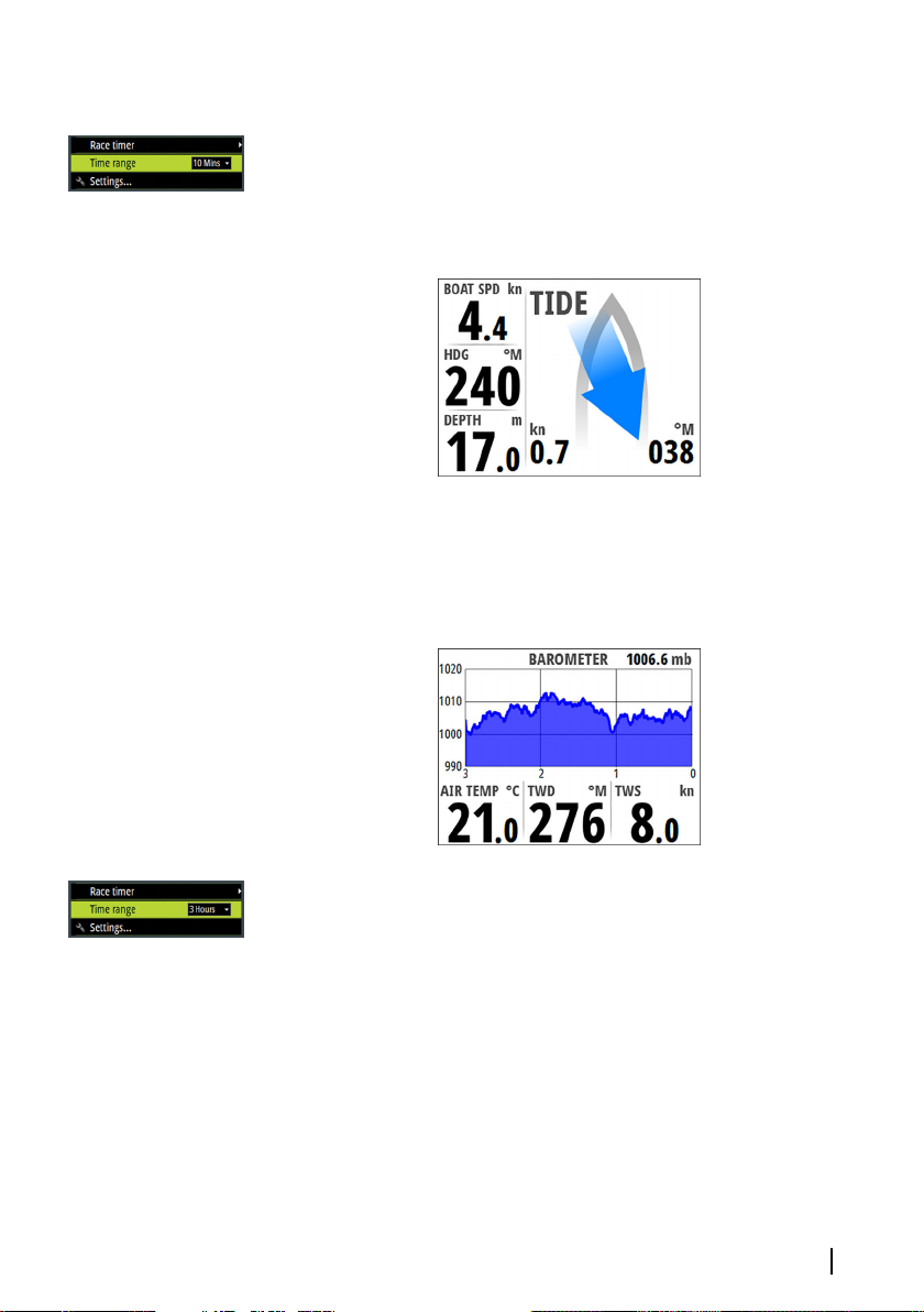
Tide page
Tidal information shown relative to the yacht's bow.
Weather page
Weather data shown graphically along with environmental data for
easy visualization.
The barometer time period can be set to show from 3 hours until 48
hours history. You change the period from the menu or by using
the arrow keys.
Pages | Triton2 Operator manual
21
Page 22
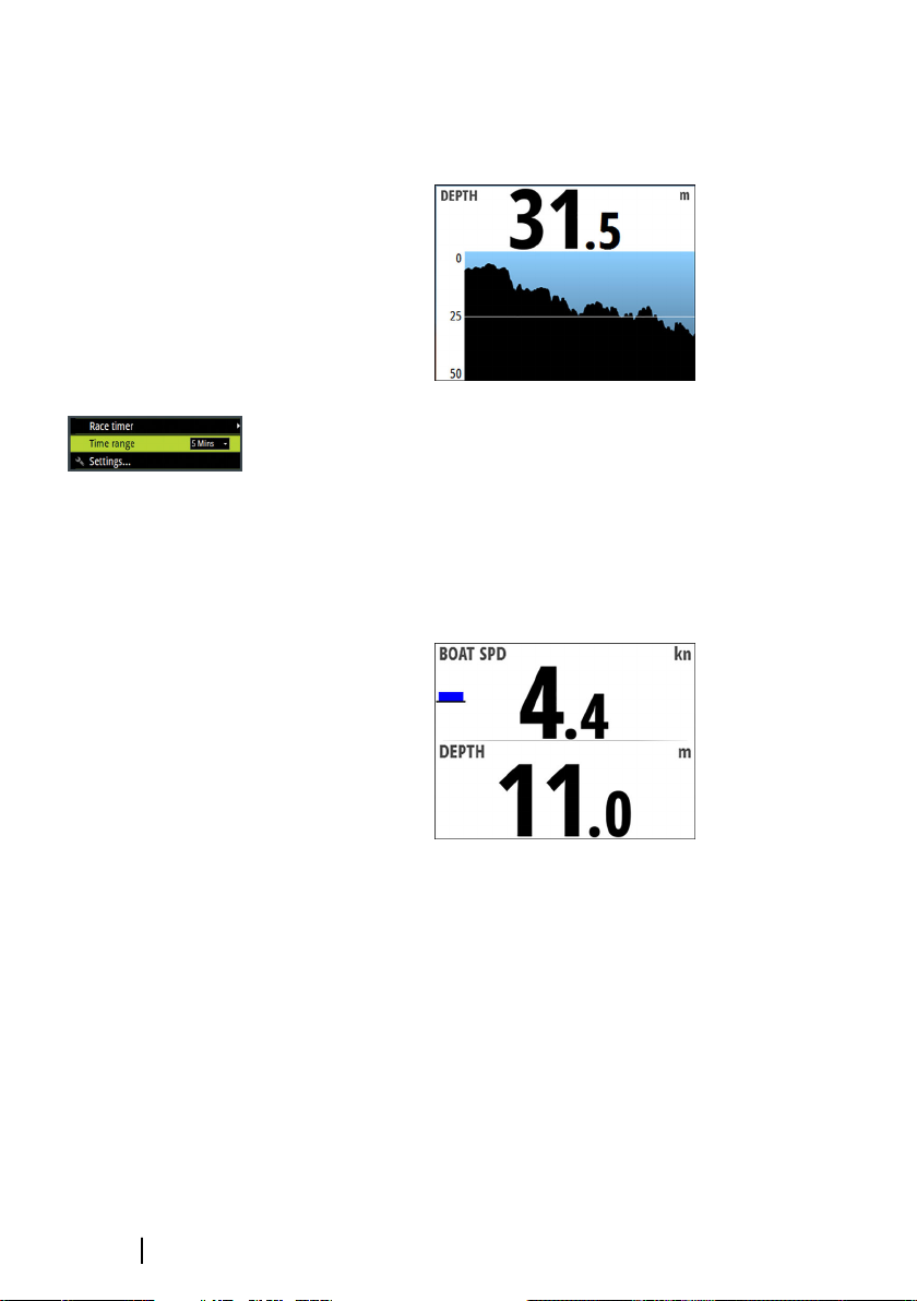
Depth history page
Current depth and histogram of recorded depth data.
The Depth histogram time period can be set to show 5, 10, 30 or 60
minutes history.
You change the period from the menu or by using the arrow keys.
Speed/Depth page
Basic speed and depth. Speed field includes an acceleration
bargraph.
22
Pages | Triton2 Operator manual
Page 23
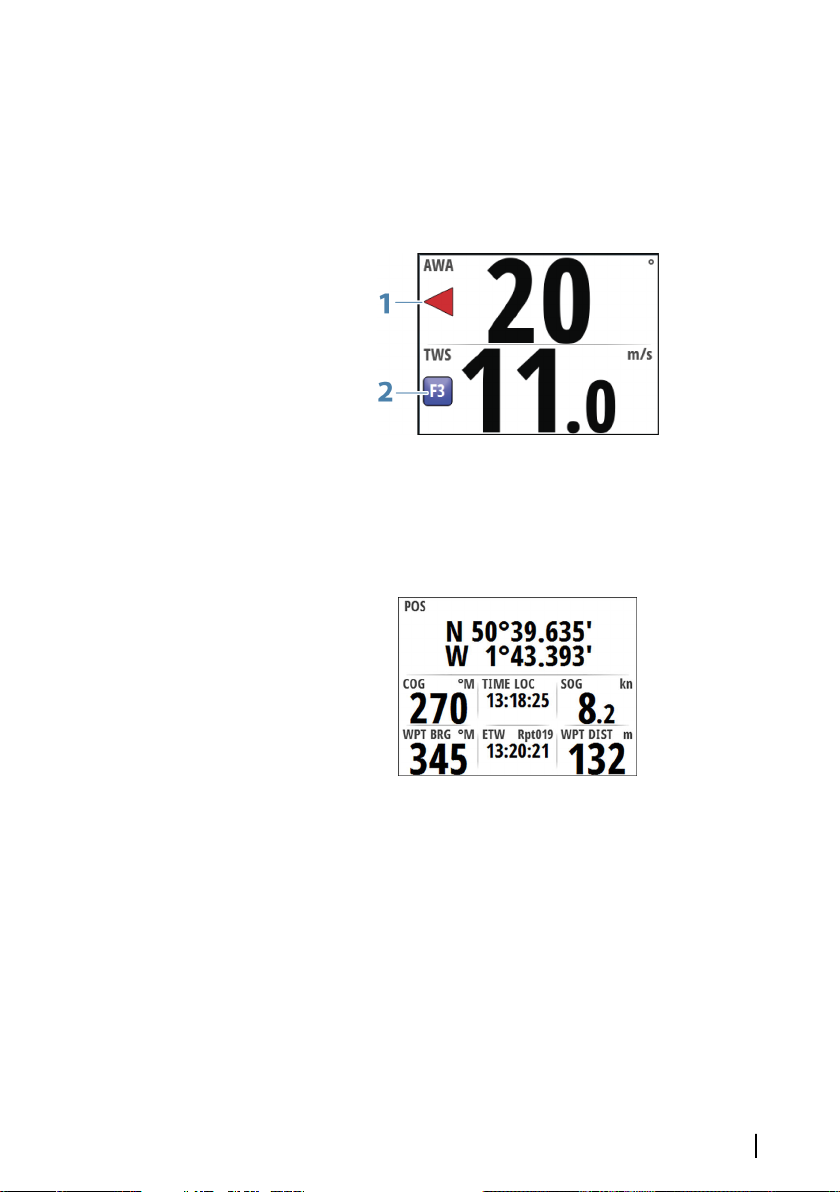
Wind Angle speed page
Apparent angle and true wind speed.
The wind angle indicator (1) is red for port and green for starboard
tack. The true wind speed field includes a Beaufort scale indicator
(2).
GPS page
GPS and navigation information. If not navigating the navigation
fields show dashes.
Pages | Triton2 Operator manual
23
Page 24
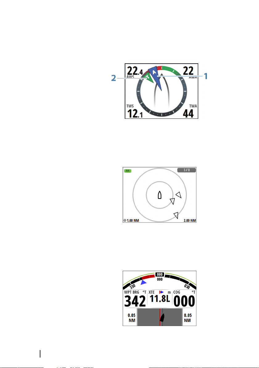
Composite Wind
Easy visualization of wind information.
Apparent wind angle indicator (1) and true wind angle indicator (2).
AIS page
Showing AIS targets within selected range. Refer to "AIS" on page
31.
24
Steering
Navigational data, including an easy visualization of compass
heading.
Pages | Triton2 Operator manual
Page 25
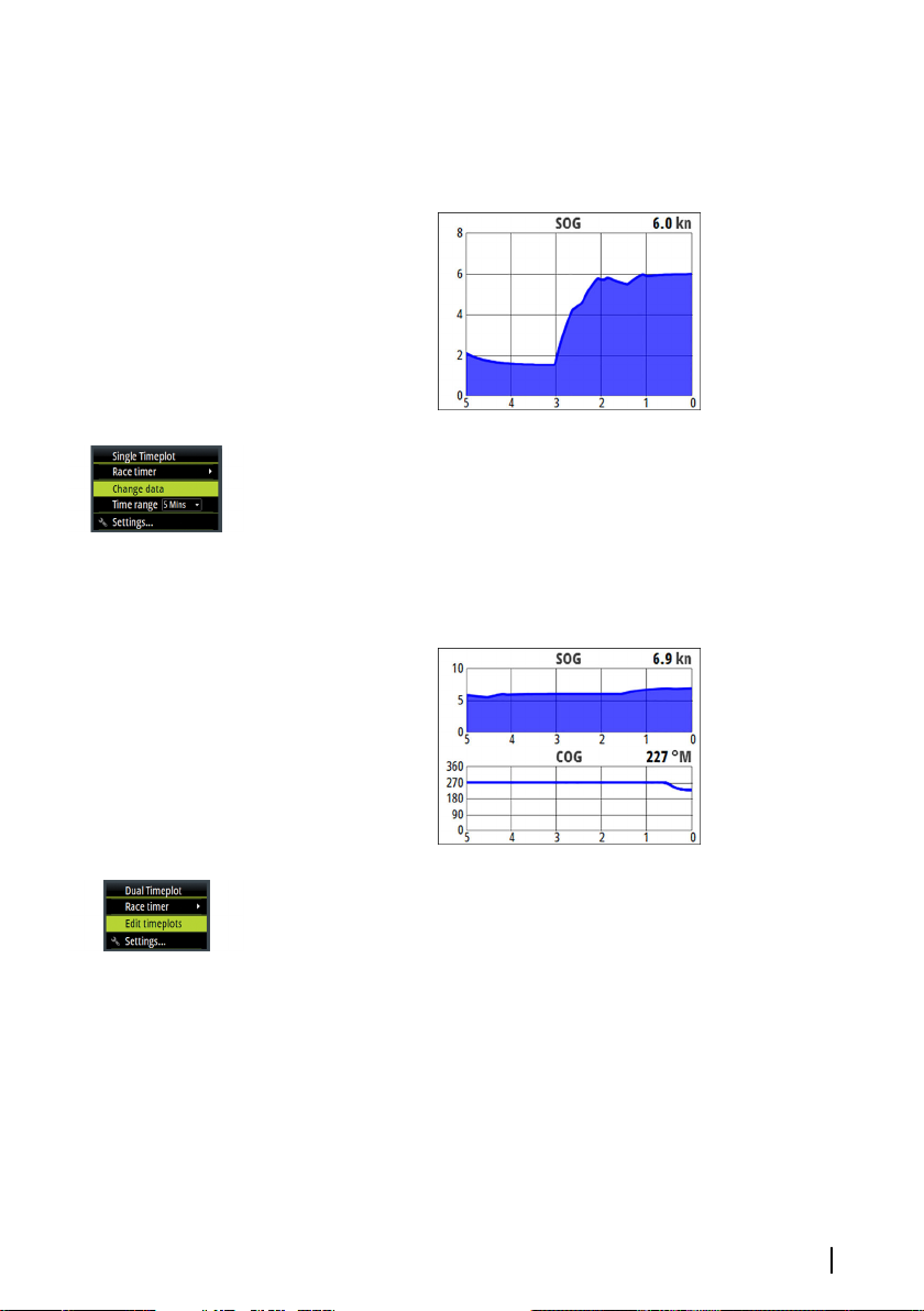
Single time plot
Easy visualization showing current and historical data plotted over a
specified time scale.
You can change data and time period from the menu.
The time period can also be adjusted by using the arrow keys.
Dual time plot
Easy visualization showing current and historical data plotted over a
specified time scale.
You can change data and time period for each of the time plots
from the menu.
Configuring data pages
Replacing a page
Any enabled page can be replaced with one of the other
predefined pages, or by a template page if you want to create a
custom page.
Pages | Triton2 Operator manual
25
Page 26
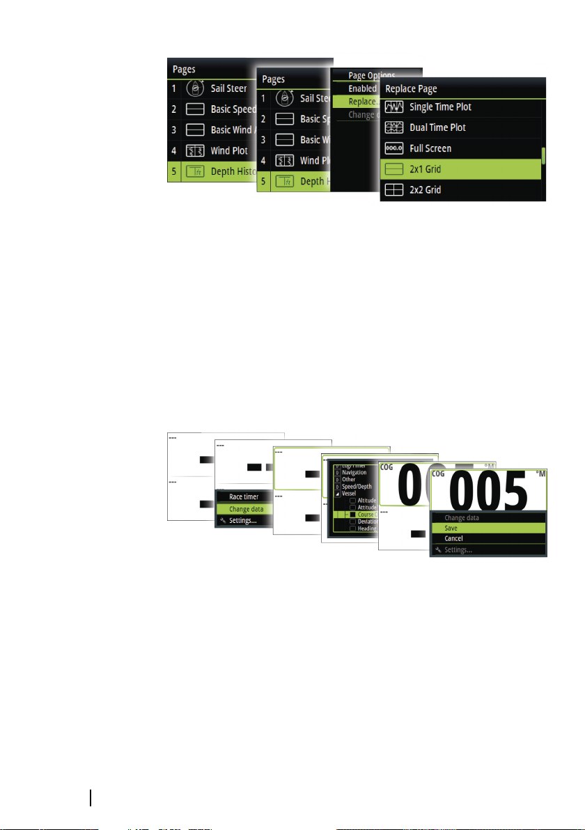
Creating/editing a custom page
A custom page is created in a two steps process:
• Replacing one of the active pages with a template page (ref
above)
• Selecting data for the template page's field(s)
Note: If the template page has multiple data fields you use the
Ú
arrow keys to select active field.
You can later change the data for any fields in a custom page.
Changing the range scale on analog pages
You can change the range scale for some full screen analog pages
by pressing the arrow keys.
26
Note: If the actual recorded data is greater than the selected
Ú
analog scale, the analog needle will remain at the highest point
on the scale. The digital window in the center of the display will
show the actual value.
Pages | Triton2 Operator manual
Page 27

Missing or faulty data
If a data type is missing or if the data is out of scale, there will be no
data reading on the display.
The example shows the basic Depth/Speed page with missing
speed information.
Pages | Triton2 Operator manual
27
Page 28

4
Race timer and Trip log
The Race timer and the Trip log are available from the Settings
menu.
Race timer and Trip log are temporary pages, and you cannot
configure these views as one of the user defined pages.
The Race timer and the Trip log remains on the screen until you
press the Pages key.
Race timer
The race timer can be used to countdown to zero from a specified
time, ideal for counting down to a race start. It can also be used to
count up from zero to record the elapsed time.
Note: The race timer is by default shared between all displays
Ú
on the network. All timer values are synchronized.
28
When the Race timer is running, you can stop and you can
synchronize the timer (up or down to the nearest full minute) from
any page menu, activated by pressing the MENU key.
When the Race timer is stopped, the following options are available
from the page menu:
Race timer and Trip log | Triton2 Operator manual
Page 29

Start
Starts the Race timer. If the timer was stopped and not reset, the
timer will continue counting from the time it had when it was
stopped.
Reset
Resets the Race timer to the start value.
Rolling timer
Restarts the countdown timer every time it reaches zero. It will
continue to do this until the timer is stopped or until this option is
de-selected.
Auto start trip
Enables the Trip log to record time and mileage from the moment
the countdown timer begins counting up from zero.
Set start value
To count down to a race start, a time value can be set in the Set start
value field.
When a time is present in the start value field the Race timer will
begin to count down from that number when the timer is started.
Once the time reaches zero it will begin counting up recording the
elapsed time.
Trip log
There are three log options available:
Race timer and Trip log | Triton2 Operator manual
29
Page 30

• Trip 1: records distance traveled through the water (Log input)
• Trip 2: records distance traveled via GPS input
• Log: shows total distance run from system installation or from a
system restore
Note: Trip 1 requires correctly calibrated boat speed for
Ú
accurate trip records.
Trip 2 requires a compatible GPS connected to the network.
You start, stop and reset the active Trip log from the menu,
activated by pressing the MENU key.
30
Race timer and Trip log | Triton2 Operator manual
Page 31

AIS
5
AIS
If a compatible AIS system or an NMEA 2000 VHF that can do AIS
(Automatic Identification System) is connected to the network, then
any targets detected by these devices can be displayed on the AIS
page. You can also see messages and position from SARTs and
AtoNs within the defined range.
The AIS page
The AIS page shows:
• own vessel in the center of the page
• AIS targets within set range
• AIS mode (A)
Transmitting mode
• number of displayed icons versus total number of targets (B)
• distance between range rings (C)
• selected range (D).
Silent or receive only mode
AIS target symbols
The system uses the AIS target symbols shown below:
Sleeping AIS target (not moving or at anchor).
Moving and safe AIS target with course extension line.
Dangerous AIS target, illustrated with bold line.
A target is defined as dangerous based on the CPA and
TCPA settings. Refer to "Defining dangerous vessels" on page
36.
Lost AIS target.
When no signals have been received within a time
limit, a target is defined as lost.
The target symbol represents the last valid position of
the target before the reception of data was lost.
AIS | Triton2 Operator manual
31
Page 32

Selected AIS target, activated by selecting a target
symbol.
The target returns to the default target symbol when
the cursor is removed from the symbol.
AIS SART (AIS Search And Rescue Transmitter).
Selecting a target
You use the arrow keys to select individual AIS targets on the AIS
page. When selected the target symbol change to a selected AIS
target symbol.
AIS page display options
The following options are available for displaying the AIS targets:
Range
Defines the display range on the AIS page. Selected range is
indicated in the lower right corner of the AIS page.
Icon filters
By default, all targets within the selected range are shown on the
AIS page. You can select to hide safe AIS vessels, and to not show
targets based on vessel speed.
32
Extension lines
Defines the length of course over ground and heading extension
lines for your own vessel and for other vessels.
The length of the extension lines is set to indicate the distance the
vessel will move in the selected time period.
Your own vessel heading information is read from the active
heading sensor, and COG information is received from the active
GPS. For other vessels COG data is included in the message received
from the AIS system.
AIS | Triton2 Operator manual
Page 33

Displaying target information
Displaying information for a single target
When a target is selected, you press the Enter key to display detailed
information about the selected target.
Target list
The Target list displays basic information for all received AIS targets.
By pressing the MENU key you can sort the target list by the
different information. You can also select to include all targets or
only dangerous targets in the list.
AIS messages
Receiving a message
A message received from an AIS vessel will immediately be
displayed on any page if the Vessel message is turned on in the
Alarm settings dialog. Refer to "Vessel alarms" on page 34.
List of all AIS messages
All received messages are listed in the Message listing, activated by
pressing the MENU key when the AIS page is displayed.
Select a message and press the MENU key to display the original
message.
AIS | Triton2 Operator manual
33
Page 34

Calling an AIS vessel
If the system includes a VHF radio supporting DSC (Digital Select
Calling) calls over NMEA 2000, you can initiate a DSC call to other
vessels from the Triton2.
From the Call dialog you can change channel or cancel the call. The
Call dialog is closed when the connection is established.
AIS SART
When an AIS SART (Search and Rescue beacon) is activated, it starts
transmitting its position and identification data. This data is received
by your AIS device.
If your AIS receiver is not compliant with AIS SART, it interprets the
received AIS SART data as a signal from a standard AIS transmitter.
An icon is positioned on the AIS page, but this icon is an AIS vessel
icon. If your AIS receiver is compliant with AIS SART, the following
takes place when AIS SART data is received:
• An AIS SART icon is located on the page in the position received
from the AIS SART
• An alarm message is displayed if you have enabled the siren, the
alarm message is followed by an audible alarm.
Note: The icon is green if the received AIS SART data is a test
Ú
and not an active message.
34
Vessel alarms
You can define several alarms to alert you if a target shows up
within predefined range limits, or if a previously identified target is
lost.
The alarms are activated from the Alarm Settings dialog.
AIS | Triton2 Operator manual
Page 35

For more information about alarms, refer to "Alarms" on page 57.
Dangerous vessel
Controls whether an alarm will be activated when a vessel comes
closer than the distance for CPA within the time limit for TCPA. Refer
to "Defining dangerous vessels" on page 36.
AIS vessel lost
Sets the range for lost vessels. If a vessel is lost within the set range,
an alarm occurs.
Note: The check box controls whether the alarm pop-up box is
Ú
displayed and if the siren goes on. The CPA and TCPA define
when a vessel is dangerous regardless of the enabled or
disabled state.
Vessel message
Controls whether an alarm will be activated when a message is
received from an AIS target.
AIS | Triton2 Operator manual
35
Page 36

AIS settings
Defining dangerous vessels
You can define an invisible guard zone around your vessel. When a
target comes within the set limits, the symbol changes to the
Dangerous target symbol. An alarm is triggered if activated in the
Alarm settings panel.
36
Speed and course indication
The extension line can be used to indicate speed and course for
targets, either as absolute (true) motion or relative to your vessel.
AIS icon orientation
Sets the orientation of the AIS icon, either based on heading or COG
information.
AIS | Triton2 Operator manual
Page 37

Your vessel's MMSI number
Used for entering your own MMSI (Maritime Mobile Service Identity)
number into the system. You need to have this number entered to
receive addressed messages from AIS and DSC vessels.
AIS | Triton2 Operator manual
37
Page 38

6
Autopilot
If a compatible autopilot computer is connected to the system,
autopilot functionality is available in the system.
The system does not allow for more than one autopilot computer
on the network.
The display unit automatically detects the autopilot computer
available on the network and presents settings, configuration and
user options for the connected computer.
For details about installing and configuring an autopilot computer,
refer to the separate manuals that come with the autopilot
computer.
Safe operation with the autopilot
Warning: An autopilot is a useful navigational aid,
but DOES NOT replace a human navigator.
Warning: Ensure the autopilot has been installed
correctly, commissioned and calibrated before use.
Note: You can disengage the autopilot at any time by pressing
Ú
the STBY key on the Triton2 Pilot controller.
38
Do not use automatic steering when:
• In heavy traffic areas or in narrow waters
• In poor visibility or extreme sea conditions
• When in areas where use of an autopilot is prohibited by law
When using an autopilot:
• Do not leave the helm unattended
• Do not place any magnetic material or equipment near the
heading sensor used by the autopilot system
• Verify at regular intervals the course and position of the vessel
• Always switch to Standby mode and reduce speed in due time to
avoid hazardous situations
Autopilot | Triton2 Operator manual
Page 39

Autopilot controller
<10 10>
<1
1
>
STBY AUTO
MODE
1
2
3
5
4
The autopilot is controlled by the Triton2 Pilot controller.
1 LED - Mode and alarm indicator
2 Port and starboard keys
In Standby mode: press to activate Non Follow Up mode
(NFU).
In AUTO mode:
• Press a key to change set heading 1° or 10° to port or
starboard
• For boat type set to SAIL: Press and hold both port keys or
both starboard keys to start a tack/gybe
In NoDrift mode:
• Press a key to change set heading 1° or 10° to port or
starboard
In Wind mode:
• Press to change set wind angle 1° or 10° to port or
starboard
• Press both 1° keys to start a tack/gybe
3 AUTO key
Press to activate AUTO mode.
4 MODE key
Note: Only used when the autopilot is in AUTO or
Ú
NoDrift mode.
Press once to select mode:
• For boat type set to SAIL: activates Wind mode (A)
• For other boat type settings: activates NoDrift mode (B)
Press and hold to activate NAV mode (C)
5 STBY key
Press to activate Standby mode.
Autopilot | Triton2 Operator manual
39
Page 40

Mode and alarm indication
The LED in the Autopilot controller indicates active mode and alarm
by the flashing:
• AUTO mode: solid light
• Wind mode: flashing (80% on, 20% off)
• NAV mode; flashing (40% on, 60% off)
• Alarm on the network: rapid flashing
The LED is green in Day mode and red in Night mode
Note: There is no LED indication for NoDrift and Non-Follow
Ú
modes.
The autopilot page
The content of the autopilot page varies with active mode. All
modes include:
• Performance (H5000) / Response (AC12N/AC42N) / Profile
(NAC-2/NAC-3) mode (A)
• Heading indicator, analog and digital (B)
• Autopilot mode indication (C)
• Rudder indicator, analog and digital (D)
40
For more information, refer to the separate mode descriptions and
to the "Terms and abbreviations" on page 84.
Autopilot modes
The autopilot has several steering modes. The number of modes
and features within the mode depend on the autopilot computer,
the boat type and available inputs, as explained in the description of
the following steering modes.
Autopilot | Triton2 Operator manual
Page 41

Standby mode
A
Standby mode is used when you steer the boat at the helm.
• Switch to Standby mode by pressing the STBY key.
Note: If you press one of the port or starboard keys while in
Ú
Standby mode, the autopilot will switch to Non-Follow Up
mode.
Non-Follow Up (NFU) mode
In NFU mode you can use the port and starboard keys on the
controller to operate the rudder. The rudder will move as long as
the key is pressed.
• Switch to NFU mode by pressing one of the port or starboard
keys when the autopilot is in Standby mode.
AUTO mode (Heading hold)
In AUTO mode the autopilot issues rudder commands required to
steer the vessel automatically on a set heading. In this mode the
autopilot does not compensate for any drifting caused by current
and/or wind (A).
• Switch to AUTO mode by pressing the AUTO key. When the
mode is activated, the autopilot selects the current boat heading
as the set heading.
Changing set heading in AUTO mode
You adjust the set heading by using the port or starboard keys.
Autopilot | Triton2 Operator manual
41
Page 42

An immediate heading change takes place. The new heading is
<10 10>
<1
1
>
maintained until a new heading is set.
Tacking and Gybing in AUTO mode
Tacking and Gybing in AUTO mode uses the heading as reference.
The tacking/gybing operation changes the set heading to port or
starboard with a fixed angle.
The tacking parameters are set in the Setup/Sailing parameters: The
Tack angle defines the tacking angle, while the Tack time defines
the rate of turn during the tack/gybe. Refer to "Autopilot settings" on
page 47:
• Initiate the Tack or Gybe function to port or starboard by pressing
and holding both port keys or both starboard keys on the
autopilot controller.
- The turn is started immediately to the direction selected by the
keys.
Wind mode
Note: Wind mode is only available when the boat type is set to
Ú
SAIL. It is not possible to activate wind mode if wind
information is missing.
When wind mode is engaged, the autopilot captures the current
wind angle as steering reference, and adjusts the heading of the
boat to maintain this wind angle.
Prior to entering wind mode the autopilot system must be
operating in AUTO mode and with valid input from the wind
transducer.
• Switch to Wind mode by pressing the MODE key when the
autopilot is in AUTO mode.
42
The autopilot will now keep the boat on the set wind angle until a
new mode is selected or a new wind angle is set.
Warning: In wind mode the autopilot steers to the
apparent or true wind angle and not to a compass
heading. Any wind shift could result in the vessel
steering on an undesired course.
Autopilot | Triton2 Operator manual
Page 43

Tacking and Gybing in Wind mode
<1
1
>
Tacking and Gybing in Wind mode can be performed when sailing
with apparent or true wind as the reference. In either case the true
wind angle must be less than 90 degrees (tacking) and more than
120° (gybing).
The tacking/gybing operation will mirror the set wind angle on the
opposite tack.
The rate of turn during the tack/gybe is set by the Tack time in the
Setup/Sailing menu. Refer to "Autopilot settings" on page 47.
• Initiate the Tack or Gybe function by pressing both the port and
the starboard 1° keys on the autopilot controller.
• Confirm the tack/gybe in the dialog by pressing the AUTO key
on the autopilot controller or the Enter key on the Triton2.
Note: The autopilot will temporarily add a 5 degree bear-away
Ú
on the new tack to allow the boat to pick up speed. After a
short period the wind angle will return to the set angle.
Note: If the Tack/Gybe is not confirmed the dialog will close
Ú
after 10 seconds, and the requested tack/gybe will not be
initiated.
NoDrift mode
Note: NoDrift mode is not available if the boat type is set to
Ú
SAIL.
It is not possible to select NoDrift mode if position and heading
information is missing.
In NoDrift mode the vessel is steered along a calculated track line,
from present position and in a direction set by the user. If the vessel
Autopilot | Triton2 Operator manual
43
Page 44

is drifting away from the track line due to current and/or wind (A),
A
the vessel will follow the line with a crab angle.
Prior to entering NoDrift mode the autopilot system must be
operating in AUTO mode and with valid input from GPS and
heading sensor.
• Switch to NoDrift mode by pressing the MODE key when the
autopilot is in AUTO mode
- The autopilot will draw an invisible track line based on current
heading from the vessel’s position
The autopilot will now use the position information to calculate the
cross track distance, and automatically steer along the calculated
track.
Changing set course in NoDrift mode
You adjust the set course by using the port or starboard keys.
An immediate course change takes place. The new course is
maintained until a new course is set.
Dodging
Note: Only available for AC12N/AC42N autopilot computers.
Ú
If you need to avoid an obstacle when using NoDrift mode, you can
set the autopilot to Standby mode and power steer or use the helm
until the obstacle is passed.
If you return to NoDrift mode within 60 seconds you can select to
continue on previous set bearing line.
If you do not respond, the dialog disappears and the autopilot goes
to NoDrift mode with current heading as set bearing line.
44
Heading capture
When the vessel is turning in AUTO or NoDrift mode, an instant repress on the AUTO key activates the heading capture function. This
will automatically cancel the turn, and the vessel will continue on
the heading read from the compass the very moment you pressed
the AUTO key.
Autopilot | Triton2 Operator manual
Page 45

NAV mode
Note: NAV mode requires a compatible chartplotter connected
Ú
to the network.
It is not possible to select NAV mode if heading information is
missing, or if steering information is not received from the
external chartplotter.
Warning: NAV mode should only be used in open
waters. Navigation mode must not be used while
sailing, as course changes may result in unexpected
tacks or gybes!
In NAV mode the autopilot uses steering information from an
external chartplotter to direct the vessel to one specific waypoint
location, or through a series of waypoints.
In NAV mode, the autopilot's heading sensor is used as heading
source for course keeping. Speed information is taken from SOG or
from selected speed sensor. The steering information received from
the external chartplotter alters the set course to direct the vessel to
the destination waypoint.
To obtain satisfactory navigation steering, the autopilot system
must have valid input from the chartplotter. Autosteering must be
tested and determined satisfactory prior to entering NAV mode.
Note: If the chartplotter does not transmit a message with
Ú
bearing to next waypoint, the autopilot will steer using Cross
Track Error (XTE) only. In that case you must revert to AUTO
mode at each waypoint and manually change set course to
equal bearing to next waypoint and then select NAV mode
again.
Prior to entering NAV mode the autopilot system should be
operating in AUTO mode. The chartplotter must be navigating a
route or towards a waypoint.
• Initiate NAV mode by pressing and holding the MODE key for 3
seconds when the autopilot is in AUTO mode.
• Confirm to switch to NAV mode in the dialog by pressing the
AUTO key on the autopilot controller or the Enter key on the
Triton2.
Autopilot | Triton2 Operator manual
45
Page 46

Turning in NAV mode
When your vessel reaches a waypoint, the autopilot will give an
audible warning and display a dialog with the new course
information.
There is a user defined limit for the allowed automatic course
change to next waypoint in a route. If the course change is more
than this set limit, you are prompted to verify that the upcoming
course change is acceptable.
• If the required course change to the next waypoint is less than
the course change limit, the autopilot will automatically change
the course. The dialog will disappear after 8 seconds unless
cleared by the Pages key.
• If the required course change to next waypoint is more than the
set limit, you are prompted to verify that the upcoming course
change is acceptable. If the turn is not accepted, the vessel will
continue with the current set heading.
46
Course change less than set limit Course change larger than set limit
The course change limit setting depends on the autopilot
computer:
• H5000: Fixed value (30°)
Autopilot | Triton2 Operator manual
Page 47

• NAC-2/NAC-3: Course chg confirm angle, refer to "Steering (NAC-2/
NAC-3)" on page 51
• AC12N/42N and SG05: Navigation change limit, refer to
"Automatic steering (AC12N/AC42N)" on page 55
Using the autopilot in an EVC system
When the Triton2 is connected to an EVC system via the SG05, you
can take manual control of the steering regardless of the autopilot
mode.
The mode indicator is replaced by a dash to indicate EVC override.
The system returns to Triton2 control in Standby mode if no rudder
command is given from the EVC system within a predefined period.
Autopilot alarms
You can define several alarms to alert you if the autopilot system or
autopilot sensors are failing.
The alarms are activated from the Alarm Settings dialog.
For more information about alarms, refer to "Alarms" on page 57.
Autopilot settings
The autopilot settings can be split between settings done by the
user, and settings done during installation and commissioning of
the autopilot system.
• User settings can be changed for various operational conditions
or user preferences
Autopilot | Triton2 Operator manual
47
Page 48

• Installation settings are defined during commissioning of the
autopilot system. No changes should later be done to these
settings
Both user settings and installation settings depends on which
autopilot computer that is connected to the system.
The following sections describe the settings that can be changed by
the user. The settings are described per autopilot computer.
Installation settings are available in the documentation following
the autopilot computers.
H5000 Autopilot computer
Performance (H5000)
The Performance controls the response of the autopilot steering.
There are five levels of performance modes:
• Level one consumes the least amount of power when steering
the autopilot and offers the slowest response
• Level five consumes the most power and has the highest
response
48
The performance mode is indicated in the top left corner of the
autopilot page.
Steering (H5000)
This option allows for manually changing parameters that were set
during the commissioning of the autopilot computer. For more
details of the settings, refer to the separate documentation for the
autopilot computer.
Autopilot | Triton2 Operator manual
Page 49

• Automatic response: controls the rate that which the autopilot
reacts to any environmental influences on the vessels desired
course
- Off: The autopilot will always remain in the response mode
selected
- Economy: The autopilot will need to sense large environmental
changes before increasing the response setting
- Normal: The autopilot will need to sense moderate
environmental changes before increasing the response
settings
- Sport: The autopilot will be most sensitive to changing
conditions and will automatically increase its response rate to
counter environmental changes
• Recovery: Allows the user to set the sensitivity to course errors
and how the autopilot will react to unexpected events, for
example sudden wave or wind shifts. This function allows the
autopilot to instantaneously increase the steering response to its
maximum setting (Perf 5), and make a rapid recovery. The
Recovery will automatically switch off after 15 seconds or when
the heading error has been corrected. The autopilot will then
resume the previous response setting and continue normal
operation.
- Off
- Narrow: The autopilot is most sensitive to sudden course
changes corrected
- Medium: The autopilot is configured to the medium value
when correcting sudden course changes
- Wide: The autopilot is least sensitive to sudden course changes
• Adapt: Software feature that continues to adjust parameters that
are essential for the steering performance, e.g. speed, trim,
draught and tide effects. When activated these parameters are
optimized during the voyage in response to the vessel's
behavior.
- ON/OFF
• Limits: Allows control of the True Wind Angle range where Gust
and True Wind Speed response can be configured and controlled
- TWA min: Minimum True Wind Angle that gust and True Wind
Speed response operate in.
Autopilot | Triton2 Operator manual
49
Page 50

- TWA max: Maximum True Wind Angle that gust and True Wind
Speed response operate in.
- Bear away max: Maximum angle the vessel will bear away
during stability control
- Cruising speed: The preferred cruising speed for this vessel
(comfortable and economical)
- Rudder limit: Determines the maximum rudder movement in
degrees from midship position that the autopilot can
command the rudder in the automatic modes. The Rudder
limit setting is only active during autosteering on straight
courses, NOT during course changes. Rudder limit does not
affect Non-Follow-up steering.
- Off course: Defines the limit for the off course alarm
• Manual speed: If neither boat speed or SOG data is available and
or deemed reliable a manual value for speed source can be
entered and used by the autopilot to aid steering calculations
Sailing (H5000)
Note: Gust response, TWS response and Heel
Ú
compensation settings are only available if Advanced is
enabled in the Display mode dialog. Refer to "Display mode" on
page 73.
• Wind mode: Select what wind function the autopilot will use
when in wind mode
- Auto:
If TWA is <70º: Wind mode will use AWA
If TWA is ≥70º: Wind mode will use TWA
- Apparent
- True
- Polar
50
• Gust response: Effects how the autopilot will react to rapid
changes in heel angle caused by gusts.
- Gust Min: Minimum gust in knots before gust compensation is
applied
- Response rate: Adjust how aggressively the autopilot will react
to gusts
- TWA response: Controls the size of the window in which gust
response will operate
Autopilot | Triton2 Operator manual
Page 51

• TWS response (True Wind Speed): Used to compensate for long
term changes in wind speed. If the average wind speed increases
and stays high, the boat will bear away accordingly, and remain
low to the wind until the wind decreases
- Response rate: Set the rate of TWS response. 1 = slowest
response, 10 = quickest response
• Tack angle: Controls the angle that the boat will tack to between
50º - 150º in AUTO mode
• Tack time: Controls the rate of turn (tack time) when performing
a tack in AUTO and Wind mode.
• Heel compensation: Provides protection against roll induced
broaching in heavy seas or high gust conditions by applying the
correct amount of rudder compensation before adverse events
become dangerous.
- Response rate: Set the rate of heel compensation. 1 = slowest
response, 10 = quickest response
NAC-2/NAC-3 Autopilot computer
Steering (NAC-2/NAC-3)
This option allows for manually changing parameters that were set
during the commissioning of the autopilot computer. For more
details of the settings, refer to the separate documentation for the
autopilot computer.
• Low speed / High speed
- Turn rate: The rate the vessel is turning in degrees per minute
- Rudder gain: Ratio between the heading error and the
commanded angle
Autopilot | Triton2 Operator manual
51
Page 52

- Counter rudder: Counteracts the effect of the vessel turn rate
and inertia
- Autotrim: When the vessel has a constant heading error due to
external forces such as wind and current, the Autotrim function
corrects for this by building up a constant rudder offset. The
Autotrim value is reset every time the AUTO mode is entered
or when a course change greater than approximately 20° is
made. Auto trim is automatically disabled during a turn.
- Init rudder: Defines how the system moves the rudder when
switching from power steering to an automatic mode.
• Center: Moves the rudder to zero position
• Actual: Maintains the rudder offset
- Rudder limit: Determines the maximum rudder movement in
degrees from midship position that the autopilot can
command the rudder in the automatic modes. The Rudder
limit setting is only active during autosteering on straight
courses, NOT during course changes. Rudder limit does not
affect Non-Follow-up steering.
- Off heading limit: Sets the limit for the off heading alarm. An
alarm occurs when the actual heading deviates from the set
heading more than the selected limit.
- Track response: Defines how fast the autopilot shall respond
after having registered a cross track distance
- Track approach angle: Defines the angle used when the vessel
is approaching a leg. This setting is used both when you start
navigating and when you use track offset.
- Course change confirm angle: Defines the limits for course
change to next waypoint in a route. If the course change is
more than this set limit, you are prompted to verify that the
upcoming course change is acceptable.
52
Sailing (NAC-2/NAC-3)
Note: Sailing parameters are only available when the boat type
Ú
is set to Sail.
• Wind mode: Select what wind function the autopilot will use
when in wind mode
- Auto:
If TWA is <70º: Wind mode will use AWA
If TWA is ≥70º: Wind mode will use TWA
- Apparent
Autopilot | Triton2 Operator manual
Page 53

- True
• Tack time: Controls the rate of turn (tack time) when performing
a tack in wind mode.
• Tack angle: Controls the angle that the boat will tack to between
50º - 150º in AUTO mode
• Manual speed: If neither boat speed or SOG data is available and
or deemed reliable a manual value for speed source can be
entered and used by the autopilot to aid steering calculations
AC12N/AC42N Autopilot computer
Response (AC12N/AC42N)
The AC12N/42N includes three different sets of steering modes;
High (HI), Low (LO) and Wind. The mode can be automatically or
manually selected.
The speed at which the autopilot automatically changes from LO to
HI parameters (or opposite) is determined by the Transition speed
setting, defined during the commissioning of the autopilot. Refer to
the detailed description in the autopilot computer's
documentation.
You can manually fine tune each of the three response modes.
Level 4 is default with parameter values as set by the autotune
function. If no autotune is made (not recommended) the level 4
values are the factory default values.
• A low response level reduces the rudder activity and provides a
more “loose” steering
• A high response level increases the rudder activity and provides a
more “tight” steering. A too high response level causes the boat
to start lazy-s movements.
Autopilot | Triton2 Operator manual
53
Page 54

The Wind response is used on sailboats
• Increase the Wind value if the difference between the set wind
angle and the actual wind angle is too big
• Decrease the Wind value if the actual wind angle is S-ing around
the set wind angle, or if the rudder activity is too high
The performance mode is indicated in the top left corner of the
autopilot page.
• HI-A: High response mode set automatically
• LO-A: Low response mode set automatically
• HI-M: High response mode set manually
• LO-M: Low response mode set manually
Note: If no speed input is available the autopilot defaults to LO
Ú
steering parameters when engaging an automatic mode. This is
a safety feature to prevent oversteering
Sea state filter (AC12N/AC42N)
This filter is used to reduce rudder activity and autopilot sensitivity
in rough weather.
• OFF: Seastate filter is disabled. This is the default setting.
• AUTO: Reduces rudder activity and autopilot sensitivity in rough
weather by an adaptive process. The AUTO setting is
recommended if you want to use the seastate filter.
54
• MANUAL: Linked to the steering response control settings
described previously. It may be used to manually find the
optimum combination of course keeping and low rudder activity
in rough but steady sea conditions.
Sailing (AC12N/AC42N)
Note: Sailing parameters are only available when the boat type
Ú
is set to Sail.
• Tack time: Controls the rate of turn (tack time) when performing
a tack in wind mode.
• Tack angle: Controls the angle that the boat will tack to between
50º - 150º in AUTO mode
• Wind mode: Select what wind function the autopilot will use
when in wind mode
Autopilot | Triton2 Operator manual
Page 55

- Auto:
If AWA is ≤60º: Wind mode will use AWA
If AWA is >60º: Wind mode will use TWA
- Apparent
- True
• VMG optimizing: Optimize the VMG to wind. The function will be
active for 5–10 minutes after a new wind angle has been set and
only when beating.
• Layline steering: When enabled the Cross Track Error (XTE) from
the navigator will keep the boat on the track line. If the XTE from
the navigator exceeds 0.15 Nm, the autopilot will calculate the
layline and track towards the waypoint.
Automatic steering (AC12N/AC42N)
This option allows for manually changing parameters that were set
during the commissioning of the autopilot computer. For more
details of the settings, refer to the separate documentation for the
autopilot computer.
• Transition speed: This is the speed at which the autopilot will
automatically change the steering parameter set from HI to LO
parameters, or vice versa. On power boats it is recommended to
set the Transition speed to a speed that represents the speed
where the hull begins to plane or the speed where you change
from slow to cruising speed
On sailboats the Transition speed should be set to 3-4 knots to
give the best response in a tack
• High/Low
- Rudder gain: This is the ratio between the heading error and
the commanded rudder angle. Low speed requires more
rudder gain than high speed
• Too little Rudder gain and the autopilot fails to keep a steady
course
• Too much Rudder gain gives unstable steering and reduces
speed
- Counter rudder: This parameter counteracts the effect of the
vessel turn rate and inertia. The best way of checking the value
of the Counter Rudder setting is when making turns.
- Auto trim: When the vessel has a constant heading error due to
external forces such as wind and current, the Auto trim
Autopilot | Triton2 Operator manual
55
Page 56

function corrects for this by building up a constant rudder
offset. The Auto trim value is reset every time the AUTO mode
is entered or when a course change greater than
approximately 20° is made. Auto trim is automatically disabled
during a turn.
- Rate limit: The rate the vessel is turning in degrees per minute.
• Minimum rudder: Some boats may have a tendency of not
responding to small rudder commands around the course
keeping position because of a small rudder, a rudder deadband,
whirls/disturbance of the water-stream passing the rudder or it is
a single nozzle water jet boat. By manually adjusting the
minimum rudder function, the course keeping performance
might be improved on some boats. This will however increase
the rudder activity.
• Min wind angle starboard / Min wind angle port: This is the
minimum apparent wind angle that will keep the sails well
shaped and give an acceptable thrust. This parameter will vary
from boat to boat. The setting applies for the tack-prevent
function. It also applies when the autopilot is operating in
WindNAV mode. You can select different minimum wind angles
for port and starboard. The difference between port and
starboard will be taken into account when calculating the
Distance To Turn (DTT).
56
• Navigation change limit: Defines the limits for course change to
next waypoint in a route. If the course change is more than this
set limit, you are prompted to verify that the upcoming course
change is acceptable
SG05 Autopilot computer
The SG05 Autopilot computer offers the same settings as the
AC12N/AC42N Autopilot computers. Refer to "AC12N/AC42N Autopilot
computer" on page 53.
Autopilot | Triton2 Operator manual
Page 57

7
Alarms
The system continuously checks for dangerous situations and
system faults while the system is running. The alarm system can be
activated if any alarm settings are exceeded.
Alarm indication
An alarm situation is indicated with an alarm pop-up. If you have
enabled the siren, the alarm message is followed by an audible
alarm.
A single alarm is displayed with the name of the alarm as the title,
and with details for the alarm.
If more than one alarm is activated simultaneously, the alarm popup can display 2 alarms. The alarms are listed in the order they occur
with the alarm activated first at the top. The remaining alarms are
available in the Alarms dialog.
Type of messages
The messages are classified according to how the reported situation
affects your vessel. The following color codes are used:
Color Importance
Red Critical
Orange Important
Yellow Standard
Blue Warning
Green Light warning
Acknowledging the alarms
The most recent alarm is acknowledged by pressing the Enter key.
This removes the alarm notification, and silences the alarm from all
units that belong to the same alarm group. A reminder reappears at
given intervals for as long as the alarm condition exists.
Note: An alarm received from non Navico units on the network
Ú
must be acknowledged on the unit generating the alarm.
Alarms | Triton2 Operator manual
57
Page 58

Enabling the alarm system and the alarm siren
You enable the alarm system and the alarm siren from the Alarms
menu.
Individual alarm settings
You enable/disable the single alarm and set the alarm limits from
the Alarms settings dialog.
• Press the Enter key to enable/disable the alarm
• Press the MENU key to show the menu from where you can
access the alarm limits
58
Alarm history
The Alarm history dialog stores alarm messages until they are
manually cleared.
Alarms | Triton2 Operator manual
Page 59

You show alarm details for a selected alarm and clear all alarms in
the alarm history by pressing the MENU key when the Alarm history
dialog is active.
Menu options Alarm details
Alarm limits on analog pages
The analog true wind speed (TWS) and depth full-screen pages
indicate the high and low alarm limit settings as red warning zones.
This gives you a visual indication of alarm zones.
True Wind Speed page showing
high and low true wind limits
Alarms | Triton2 Operator manual
Depth page showing
shallow and deep water limits
59
Page 60

8
Software setup
Prior to use, the Triton2 requires a number of settings be configured
in order for the system to perform as expected. Access to the
required options are found in the Settings menu, accessed from the
page menu or by pressing the MENU key twice.
Note: The following settings are described in other sections of
Ú
this manual:
"Race timer" on page 28
"Pages" on page 15
"Trip log" on page 29
"Alarms" on page 57
"Autopilot settings" on page 47
"AIS settings" on page 36
60
Remote displays
Any compatible B&G HV display connected to the network can be
configured to show desired data via the Triton2.
All HV Displays are listed in the Remote displays dialog. Displays not
present on the network are greyed out.
1. Select the type of display you want to configure
- Connected displays of the selected type are listed
2. Highlight the display you want to configure
- The HV display itself starts flashing
3. Press the MENU key to display the options available:
Software setup | Triton2 Operator manual
Page 61

• Select data: Used for defining which data that should be
displayed on the selected HV display
• White backlight: Sets the the backlight to white
Note: This option is not available for the 40/40 HV display
Ú
• Display group: Sets the network group for the unit
• Instance: Sets the network instance for the unit
For more information about network groups and instance settings,
refer to "Network" on page 69.
Calibration
Note: Once the unit is setup and before you proceed with
Ú
calibration ensure all network sources are selected and
configured. Refer to "System settings" on page 69.
Boat speed
Speed calibration is necessary to compensate for hull shape and
paddlewheel location on your boat. For accurate speed and log
readings, it is essential that the paddlewheel is calibrated.
SOG reference
This is an auto calibration option that uses speed over ground (SOG)
from your GPS, and compares the average of SOG against the
average boat speed from the speed sensor for the duration of the
calibration run.
Note: This calibration should be made in calm sea with no
Ú
effect from wind or tidal current.
Software setup | Triton2 Operator manual
61
Page 62

• Bring the boat up to cruising speed (above 5 knots), then
x
BA
• Select the SOG reference option
When the calibration is completed the Boat speed calibration scale
will show the adjusted percentage value of the boat speed.
Distance reference
Allows you to calibrate the log via a distance reference. You will
need to complete consecutive runs, under power at a constant
speed made along a given course and distance.
Note: The distance should be greater than 0.5 NM, ideally 1 NM.
Ú
To eliminate the effect of tidal conditions it is advisable to
perform at least two runs, preferably three, along the measured
course.
Referring to the diagram, A and B are the markers for each run. X is
the actual distance for each run.
• Enter the desired distance in nautical miles that you would like to
calculate the distance reference over
• When the boat gets to the predetermined starting position of the
distance reference calculation, start the calibration timer
• As the boat passes marks A and B on each run, instruct the
system to start and stop and finally OK to end calibration.
62
Use SOG as boat speed
If boat speed is not available from a paddle wheel sensor, it is
possible to use speed over ground from a GPS. SOG will be
displayed as boat speed and used in the true wind calculations and
the speed log.
Software setup | Triton2 Operator manual
Page 63

Wind
MHU (Masthead unit) alignment
This provides an off set calibration in degrees to compensate for any
mechanical misalignment between the masthead unit and the
center line of the vessel.
To check the masthead unit alignment error we recommend you
use the following method which involves a sailing trial:
• Sail on a starboard tack on a close hauled course and record the
wind angle, then repeat the process on a port tack
• Divide the difference between the two recorded numbers and
enter this as the wind angle off set
If the starboard apparent wind angle is greater than the port angle,
then divide the difference by 2 and enter this as a negative offset.
If the port angle is greater than the starboard then divide the
difference by 2 and enter this as a positive offset.
Enter the offset it into the MHU Align calibration field.
True wind angle
Note: This option is only available if an H5000 CPU is connected
Ú
to the system.
There are two methods of calibrating TWA:
• monitoring true wind direction from tack to tack
• use the compass to verify the angles the yacht is tacking or
gybing through
Start the TWA calibration process for either method by setting the
boat up to do a number of tacks upwind or gybes downwind in as
steady conditions as possible.
• Method 1 - Monitor True Wind Direction changes
If an error is seen in true wind direction, then the following rule
applies:
- If true wind direction is being shown as a lift each time you
tack then True Wind Angle is reading too wide, half the error
must be subtracted from the TWA correction table
- If true wind direction is being shown as a header each time
you tack then True Wind Angle is reading too narrow, add half
the error to the TWA correction table
Software setup | Triton2 Operator manual
63
Page 64

• Method 2 - Monitor tacking angles
If according to the compass you are tacking through an angle
different than the sum of the True Wind Angles on each tack
(Port TWA + Starboard TWA) then the following rule applies:
- If the tack angle < the sum of the TWA’s, the True Wind Angle
is reading too wide, half the error must be subtracted from the
TWA correction table
- If the tack angle > the sum of the TWA’s, the True Wind Angle
is reading too narrow, add half the error to the TWA correction
table
Note: Ensure your compass is correctly calibrated before
Ú
carrying out TWA calibration using either method.
True wind speed
Note: This option is only available if an H5000 CPU is connected
Ú
to the system.
True Wind Speed errors are seen from sailing upwind to downwind.
This is due to the acceleration of the airflow over the top of the mast
and around the sails when sailing downwind. -10% is the default
value for TWA calibration. Monitoring the change in True Wind
Speed from close hauled to broad reaching will enable further
refinement of this calibration value.
64
Motion
Note: This option is only available if an H5000 CPU is connected
Ú
to the system.
A 3D Motion sensor and mast height value is required in
conjunction with a CPU running Hercules level software or
greater to use this feature.
When the wind is measured it is initially corrected for masthead unit
alignment offset and mast rotation. Set the mast height and tick
Motion Correction for motion correction to be applied to measured
wind speed and wind angle.
Depth
Depth offset
All transducers measure water depth from the transducer to the
bottom. As a result, water depth readings do not account for the
Software setup | Triton2 Operator manual
Page 65

distance from the transducer to the lowest point of the boat (for
A B C
+0.5
+0.0
-2.0
example; bottom of the keel, rudder, or propeller) in the water or
from the transducer to the water surface.
• For depth below keel (A): Set the distance from transducer to the
bottom of the keel as a negative value. For example, -2.0.
• For depth below transducer (B): no offset required.
• For depth below surface (waterline) (C): Set the distance from
transducer to the surface as a positive value. For example,+0.5.
Aft depth offset
This option allows the system to display two depth readings.
The Aft depth is calibrated in the same manner as the Depth offset.
Ú
Heading
Ú
Software setup | Triton2 Operator manual
Note: Aft Depth is only available when a valid signal is received
from a second and compatible NMEA 2000 or NMEA 0183
device.
Note: All magnetic compasses must be calibrated to ensure
correct heading reference.
The calibration must be made on the active compass.
The calibration should be done in calm sea conditions and with
minimal wind and current to obtain good results.
65
Page 66

Offset
B
A
x
20%
0
30˚
030˚
B
C
A
The Offset option is used for compensating for any difference
between the boat’s center line (A) and the compass lubber line (B).
1. Find the bearing from the boat position to a visible object. Use a
chart or a chart plotter
2. Steer the boat so that the center line of the boat is aligned with
the bearing line pointing towards the object.
3. Change the offset parameter so that the bearing to the object
and the compass readout becomes equal.
Note: Make sure that both the compass heading and the
Ú
bearing to the object have the same unit (°M or °T).
User triggered calibration
Note: Before the calibration is started, make sure that there is
Ú
enough open water around the vessel to make a full turn.
The Calibrate option is used for manually starting the heading
calibration procedure.
During this calibration, the compass measures the magnitude and
direction of the local magnetic field.
The illustration shows magnitude of local field in percentage of
earth's magnetic field (A), direction of local field (B) with respect to
the boat's centerline (C).
Follow the on-screen instruction, and use about 60-90 seconds to
make a full circle. Keep turning until the system reports a pass.
• If the local magnetic field is stronger than the earth’s magnetic
field (the local field is reading more than 100%), the compass
calibration will fail.
• If the local field is reading more than 30%, you should look for
any interfering magnetic objects and remove them, or you
should move the compass to a different location. The (local) field
angle guides you to the local interfering magnetic object.
Note: In certain areas and at high latitudes the local magnetic
Ú
interference becomes more significant, and heading errors
exceeding ±3° may have to be accepted.
66
Software setup | Triton2 Operator manual
Page 67

Automatic calibration
The Auto calibrate option is used for compasses that offers a fully
automatic calibration procedure.
See more instructions in the documentation delivered with your
compass.
Magnetic variation
Defines how magnetic variation is handled by the system.
• Auto: Receives variation data from a network source
• Manual: Used for manually entering a value for the magnetic
variation
Use COG as heading
If heading data is not available from a compass sensor, it is possible
to use COG from a GPS. COG will be used in the true wind
calculations.
Note: The autopilot cannot be operated using COG as the
Ú
heading source. COG cannot be calculated when stationary.
Heel/Trim
If a suitable sensor is fitted, the system will monitor the inclination of
the vessel. The offset value should be entered to adjust the readings
so that while the vessel is stationary at the dock, the Heel and Trim
value reads 0.
Environment
If a suitable sensor is fitted, the system will monitor the current
sea/air temperature and barometric pressure.
The offset value to be entered should adjust the reading from the
sensor to match a calibrated source.
Rudder
Starts the automatic calibration of the rudder feedback. This
procedure sets the correct relationship between the physical rudder
movement and the rudder angle readout.
Follow the instructions on the display to perform the rudder
feedback calibration procedure.
Software setup | Triton2 Operator manual
67
Page 68

Laylines
Note: This option is only available if an H5000 CPU is connected
Ú
to the system.
Tidal flow correction
Calculates the tidal flow and offsets the laylines accordingly.
Target wind angle
True wind angle is used in the layline calculations. There are 3
options available:
• Polar: Takes the target wind angle from your polar table in the
H5000 CPU
• Actual: Takes the current value of target wind angle
• Manual: Allows for manually entering upwind and downwind
values
Layline limits
When selected will show a shaded area indicating the minimum
and maximum tack/gybe time period either side of the layline. This
can be set to 5, 10, 15 & 30 minute increments.
68
Advanced
This option is used for manually applying an offset to the displayed
data for third party sensors which cannot be calibrated through the
Triton2.
Software setup | Triton2 Operator manual
Page 69

Damping
If data appears erratic or too sensitive, damping may be applied to
make the information appear more stable. With damping set to off,
the data is presented in raw form with no damping applied.
Note: Damping settings are applied to units belonging to the
Ú
same damping group. Refer to "Network groups" on page 72.
System settings
Network
Sources
Data sources provide live data to the system.
The data may originate from modules internal to the unit (for
example internal GPS or sonar), or external modules connected to
the NMEA 2000 or via NMEA 0183 if available on the unit.
When a device is connected to more than one source providing the
same data, the user can choose the preferred source. Before
commencing with source selection make sure all external devices
and the NMEA 2000 backbone are connected and are turned on.
• Auto select: Looks for all sources connected to the device. If more
than one source is available for each data type, selection is made
from an internal priority list. This option is suitable for the
majority of installations.
• Manual source selection: Manual selection is generally only
required where there is more than one source for the same data,
and the automatically selected source is not the one desired.
Device list
The Device list shows the devices that provide data. This may
include a module inside the unit, or any external NMEA 2000 device.
Software setup | Triton2 Operator manual
69
Page 70

Selecting a device in this list will bring up additional details and
actions:
All devices allow allocation of an instance number in the configure
option. Set unique instance numbers on any identical devices on
the network to allow for the unit to distinguish between them. The
data option shows all data being output by the device. Some
devices will show additional options specific to the device.
Note: Setting the instance number on a 3rd party product is
Ú
typically not possible.
Diagnostics
The NMEA 2000 tab on the diagnostics page can provide
information useful for identifying an issue with the network.
70
Note: The following information may not always indicate an
Ú
issue that can be simply resolved with minor adjustment to
network layout or connected devices and their activity on the
network. However, Rx and Tx errors are most likely indicating
issues with the physical network, which may be resolved by
correcting termination, reducing backbone or drop lengths, or
reducing the number of network nodes (devices).
Software setup | Triton2 Operator manual
Page 71

Bus state
Simply indicates whether the bus is powered, but not necessarily
connected to any data sources. However, if bus shows as ‘off’, but
power is present along with an increasing error count, it is possible
that termination or cable topology is incorrect.
Rx Overflows
The unit received too many messages for its buffer before the
application could read them.
Rx Overruns
The unit contained too many messages for its buffer before the
driver could read them.
Rx/Tx Errors
These two numbers increase when there are error messages, and
decrease when messages are received successfully. These (unlike
the other values) are not a cumulative count. Under normal
operation these should be at 0. Values around 96 upwards indicate
a heavily error prone network. If these numbers go too high for a
given device, it will automatically drop off the bus.
Rx/Tx Messages
Shows actual traffic in and out of device.
Bus Load
A high value here indicates network is near full capacity. Some
devices automatically adjust rate of transmission, if network traffic is
heavy.
Fast Packet Errors
Cumulative counter of any fast packet error. This could be a missed
frame, or a frame out of sequence etc. NMEA 2000 PGNs are made
of up to 32 frames. The entire message will be discarded when a
frame is missed.
Note: Rx and Tx Errors often indicate an issue with the physical
Ú
network, which may be resolved by correcting termination,
reducing backbone or drop lengths, or reducing the number of
network nodes (devices).
Software setup | Triton2 Operator manual
71
Page 72

Network groups
The Network Group function is used to control parameter settings,
either globally or in groups of units. The function is used on larger
vessels where several units are connected to the network. By
assigning several units to the same group, a parameter update on
one unit will have the same effect on the rest of the group
members.
Units
Provides setup of units of measure used on various data types.
Decimal places
Defines number of decimals used for speed and sea temperature.
Key beeps
Controls the loudness of the beep sound when a key is pressed.
Default setting: Loud
Language
Controls the language used on this unit for panels, menus, and
dialogs. Changing the language causes the unit to restart.
72
Time
Controls the local time zone offset, and the format of the time and
date.
Display setup
Displays the Display setup dialog.
The following options are available:
• Backlight level: Adjusts the backlight level from Min (10%) to Max
(100%) in 10% increments
- When the Backlight level field is active, subsequent presses on
the backlight key adjusts backlight level in decrements of 30%
• Display group: Defines which network group the unit belongs to
• Night mode: Activates/deactivates the night mode color palette
• Night mode color: Sets the night mode color palette
Software setup | Triton2 Operator manual
Page 73

• Invert day color: Changes the background color for the pages
from default white to black
• Sleep: Turns the backlight for screen and keys off to save power
Display mode
The Triton2 unit can set up as an instrument only, as an autopilot
display only, or as a combination of those two display modes.
• Instrument display only: Displays active data pages. The Autopilot
page can be one of these data pages
• Autopilot display only: Displays only the autopilot page
• Autopilot display when engaged: Switches automatically to the
Autopilot page when the autopilot is switched to an automatic
mode. When the autopilot is switched to Standby mode the
display switches back to the previous page. This behaviour does
not require that an Autopilot page selected is as one of the 8
enabled pages
The Display mode dialog have the following additional options:
• Show MOB: Switches automatically to the MOB page if a Man
Over Board event is triggered from another system on the
network. Refer to "Man Over Board (MOB)" on page 13
• Show autopilot advanced settings: Displays all available autopilot
settings. Refer to "Sailing (H5000)" on page 50.
Files
File management system. Used to browse the contents of the unit's
internal memory and the content of a device plugged into the unit's
USB port.
Software setup | Triton2 Operator manual
73
Page 74

Simulate
Runs the display with simulated data. Use the simulator to become
familiar with your unit before using it on the water.
When activated, the simulator mode is indicated on the display.
Restore defaults
Allows you to select which settings are to be restored to their
original factory settings.
Engine setup
Vessel setup
Set the number of engines, fuel tanks and total fuel capacity.
Engine display setup
A maximum of two engine’s data can be shown on each gauge.
The Engine display setup defines which engine’s data should be
displayed on a gauge if you have more than 2 engines.
Gauge limits
Sets the RPM and vessel fuel rate limits.
Note: These limits are a visual guide on the data pages. They do
Ú
not set any alarms.
74
Global reset
Resets the source selection on all displays connected to the
network.
About
Displays copyright information, software version, and technical
information for this unit.
Software setup | Triton2 Operator manual
Page 75

9
Maintenance
Preventive maintenance
The unit does not contain any field serviceable components.
Therefore, the operator is required to perform only a very limited
amount of preventative maintenance.
It is recommended that you always fit the supplied protective sun
cover when the unit is not in use.
Cleaning the display unit
A proper cleaning cloth should be used to clean the screen, where
possible. Use plenty of water to dissolve and take away salt remains.
Crystalized salt may scratch the coating if using a damp cloth. Apply
minimal pressure to the screen.
Where marks on the screen cannot be removed by the cloth alone,
use a 50/50 mixture of warm water and isopropyl alcohol to clean
the screen. Avoid any contact with solvents (acetone, mineral
turpentine, etc.), or ammonia based cleaning products, as they may
damage the anti-glare layer or plastic bezel.
To prevent UV damage to the plastic bezel, it is recommended that
the sun cover be fitted when the unit is not in use for an extended
period.
Checking the connectors
The connectors should be checked by visual inspection only.
Push the connector plugs into the connector. If the connector plugs
are equipped with a lock, ensure that it is in the correct position.
Software update
The Triton2 includes a USB port of the back of the units. You use this
port for software updates.
You can update the software for the Triton2 unit itself and for NMEA
2000 sensors connected to the network from the Triton2.
You can check the units software version from the About dialog.
Maintenance | Triton2 Operator manual
75
Page 76

The software version for connected NMEA 2000 sensors is available
in the Device list.
The latest software is available for download from our website:
www.bandg.com.
Software update for the unit
1. Download the latest software from our website:
www.bandg.com, and save it to a USB device
2.
Insert the USB device to the Triton2 unit, and restart the Triton
unit
- The upgrade will now start automatically the upgrade
procedure for all units
3. Remove the USB device when the update is completed.
2
76
Warning: Do not remove the USB device until the
update is completed. Removing the USB device before
the update is completed may damage the unit.
Maintenance | Triton2 Operator manual
Page 77

Software update for remote devices
1. Download the latest software from our website:
www.bandg.com, and save it to a USB device
2.
Insert the USB device to the Triton2 unit
3. Start the File explorer, and select the update file on the USB
device
4. Start the update from the file details dialog
5. Remove the USB device when the update is completed.
Maintenance | Triton2 Operator manual
77
Page 78

Menu flow chart
The system includes two menu categories: Page menus and
Settings menu.
10
Each page has a Page menu, accessed by pressing the MENU key
once. The page menu includes basic functions for that panel. All
page menus include access to the Race timer and to the Settings
menu.
The Settings menu is accessed from the page menus or by pressing
the MENU key twice. The Settings menu gives access to Race timer
and Trip log, and to settings for the sensors, the vessel and for the
system.
Page menu, SailSteer page Settings menu
78
Page menus
Each page has a page menu, accessed by pressing the MENU key.
If relevant, the page menu includes basic functions for that panel.
All page menus include access to the Race timer and to the Settings
dialog.
Settings menu
Level 1 Level 2
Race timer Race Timer
Pages Pages...
AutoScroll
AutoScroll time
Menu flow chart | Triton2 Operator manual
Page 79

Level 1 Level 2
Remote displays 10/10 displays...
20/20 displays...
30/30 displays...
40/40 displays...
Calibration Boat speed...
Wind...
Depth...
Heading...
Heel/Trim...
Environment...
Rudder...
Laylines...
Advanced...
Damping Heading
Apparent wind
True wind
Boat speed
SOG
COG
Heel Angle
Trim Angle
Tide
Trip log Trip 1...
Trip 2...
Log...
Alarms Alarm history...
Alarm settings...
Alarms enabled
Siren Enabled
Menu flow chart | Triton2 Operator manual
79
Page 80

Level 1 Level 2
Autopilot, H5000
Refer to the H5000 Installation
manual (988-10635-00n)
Autopilot, NAC-2 and NAC-3
** Refer to the NAC-2/NAC-3
Commissioning manual
(988-11233-00n)
Autopilot, AC12N, AC42N
and SG05
*** Refer to the AC12N/AC42N
Installation manual
(988-10276-00n)
AIS Dangerous vessels...
Performance mode
Steering
Sailing
Installation *
Steering
Sailing
Installation **
Response
Sea state filter
Sailing
Automatic steering
Installation ***
Speed and course
AIS icon orientation
MMSI...
80
Menu flow chart | Triton2 Operator manual
Page 81

Level 1 Level 2
System Network
Units
Decimal places
Key beeps
Language
Time...
Display Setup
Display mode...
Files
Simulate
Restore defaults...
Engine setup
Global reset...
About
Menu flow chart | Triton2 Operator manual
81
Page 82

Technical specification
11
Dimensions
Weight 0.32 kg (0.7 lbs)
Power consumption 1.8 Watts
Key backlight off 0.54 W
Key backlight max 1.35 W
Network load 3 LEN
Color Black
Display
Resolution 320 x 240 pixels
Illumination
Environmental protection
Waterproof rating IPx7
Humidity 100% RH
Temperature
Operating -25° to +65ºC (-13°F to +149 ºF)
Storage -40° to +85ºC (-40°F to +185 ºF)
Refer to "Dimensional drawing" on
page 83
Size 4.1" (diagonal). 4:3 Aspect ratio
Transmissive TFT-LCD. White
Type
LED backlight
White for day mode. Red, green,
blue or white for night mode
82
Technical specification | Triton2 Operator manual
Page 83

Dimensional drawing
118 mm (4.64")
115 mm (4.52")
8 mm
(0.31")
36.5 mm
(1.43")
28.5 mm
(1.12")
97.5 mm (3.83")
12
Dimensional drawing | Triton2 Operator manual
83
Page 84

Terms and abbreviations
This list shows terms and abbreviations used in the pages and in
dialogs in the Triton2 system.
13
AIR TEMP Air temperature
AIS Automatic Identification System
AVG SPD Average speed
AWA Apparent wind angle
AWS Apparent wind speed
BSPD Boat speed
BTW Bearing to waypoint
BWW Bearing Waypoint To Waypoint
COG Course Over Ground
CTS Course To Steer
DGPS Differential Gps
DTW Distance to next waypoint
DSC Digital Selective Calling
EPFS Electronic Position Fixing System
EPIRB Emergency Position Indicating Radio Beacon
ETA Estimated Time Of Arrival
ETW Estimated time of arrival to next waypoint
GLONASS Global Orbiting Navigation Satellite System
GMDSS Global Maritime Distress And Safety System
GNSS Global Navigation Satellite System
GPS Global Positioning System
HDG Heading
Km Kilometer
KN Knots
LL DIST Layline distance
LL TIME Layline time
m Meters
84
Terms and abbreviations | Triton2 Operator manual
Page 85

MAX SPD Maximum speed
MIN Minimum
MOB Man Over Board
NM Nautical Mile
OPP HDG Heading on opposite tack
POS Position
RM Relative Motion
RNG Range
ROT Rate Of Turn
RTE Route
SAR Search And Rescue
SOG Speed Over Ground
SPD Speed
STBD Starboard
STW Speed Through Water
TCPA Time To Closest Point Of Approach
TGT Target
TIME LOC Local time
TM True Motion
TRK Track
TRK CRS Track course to next waypoint
TWA True wind angle
TWD True wind direction
TWS True wind speed
WOL Wheel Over Line
WOP Wheel Over Point
WPT Waypoint name
WPT BRG Bearing to waypoint
WPT DIST Distance to waypoint
XTE Cross track error
Terms and abbreviations | Triton2 Operator manual
85
Page 86

Supported data
NMEA 2000 PGN (transmit)
14
NMEA 2000 PGN (receive)
59904 ISO Request
60928 ISO Address Claim
126208 ISO Command Group Function
126996 Product Info
127258 Magnetic Variation
59392 ISO Acknowledgement
59904 ISO Request
60928 ISO Address Claim
126208 ISO Command Group Function
126992 System Time
126996 Product Info
127237 Heading/Track Control
127245 Rudder
127250 Vessel Heading
127251 Rate of Turn
127257 Attitude
127258 Magnetic Variation
127488 Engine Parameters, Rapid Update
127489 Engine Parameters, Dynamic
127493 Transmission Parameters, Dynamic
127505 Fluid Level
127508 Battery Status
128259 Speed, Water referenced
128267 Water Depth
86
Supported data | Triton2 Operator manual
Page 87

128275 Distance Log
129025 Position, Rapid Update
129026 COG & SOG, Rapid Update
129029 GNSS Position Data
129033 Time & Date
129038 AIS Class A Position Report
129039 AIS Class B Position Report
129040 AIS Class B Extended Position Report
129041 AIS aids to Navigation
129283 Cross Track Error
129284 Navigation Data
129283 Cross Track Error
129284 Navigation Data
129539 GNSS DOPs
129540 GNSS Sats in View
129794 AIS Class A Static and Voyage Related Data
129801 AIS Addressed Safety Related Message
129802 AIS Safety Related Broadcast Message
129808 DSC Call Information
129809 AIS Class B “CS” Static Data Report, Part A
129810 AIS Class B “CS” Static Data Report, Part B
130074 Route and WP Service - WP List - WP Name & Position
130306 Wind Data
130310 Environmental Parameters
130311 Environmental Parameters
130312 Temperature
130313 Humidity
130314 Actual Pressure
130576 Small Craft Status
130577 Direction Data
Supported data | Triton2 Operator manual
87
Page 88

*988-11214-001*
 Loading...