

Page 1

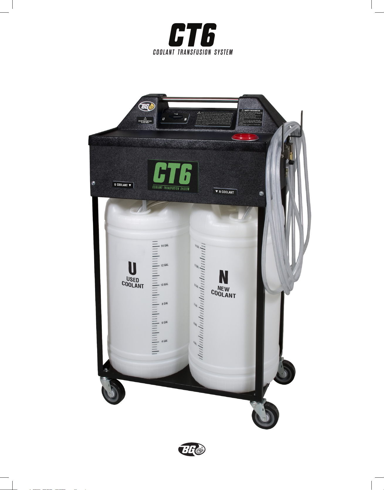
COOLANT TRANSFUSION SYSTEM
Reference Manual
Page 2
ORIGINAL INSTRUCTIONS ©copyright 2015 BG Products, Inc. • Wichita, Kansas 67213 • www.bgprod.com
1
Page 3
ORIGINAL INSTRUCTIONS ©copyright 2015 BG Products, Inc. • Wichita, Kansas 67213 • www.bgprod.com
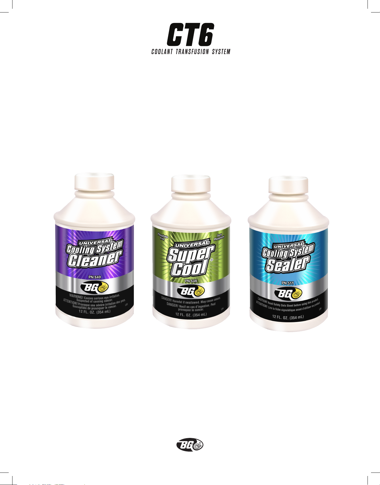
BG Cooling System Service
PRODUCTS
BG Universal Cooling
System Cleaner
PN 540
2
BG Universal
Super Cool
PN 546
®
BG Universal Cooling
System Sealer
PN 511
Page 4

ORIGINAL INSTRUCTIONS ©copyright 2015 BG Products, Inc. • Wichita, Kansas 67213 • www.bgprod.com
Specifications
Height: 48.1 inches/ 1.22 Meter
Width: 30.1 inches/.76 Meter
Depth: 17.5 inches/.44 Meter
Construction: Steel frame with heavy duty casters
PVC plastic skin and console
Power Requirements: 12 Volt DC
Process Rate: Average transfusion time is 10–20 minutes,
depending on condition and model of vehicle
Process Method: In loop with vehicle’s cooling system using pump
to assist with delivery of new coolant while
transferring used coolant to machine.
MADE IN U.S.A.
Limited Warranty
This product is warranted by BG Products, Inc. to be free of defects in workmanship and materials for a period of one (1) year from the date of purchase by original purchaser. If the product fails
within this period, it will be repaired or replaced at seller’s option, provided (1) the product is submitted with proof of purchase date and (2) transportation charges are prepaid to the nearest Service
Center. Liability under this warranty is expressly limited to repairing or replacing the product or
parts thereof. This warranty does not apply to product or parts broken by accident, negligence,
overload, abuse, or if they have been tampered with or altered in any way. This warranty does not
apply to service hoses and adaptors which may need replacing due to normal wear. If this warranty
does not apply, then the purchaser shall pay all costs for labor, material and transportation.
Note: The use of this apparatus for any purpose other than the services described will render this
warranty null and void, as will the use of any chemicals other than the BG products described in
this manual. No other warranties are expressed or implied.
3
Page 5

Page 6
ORIGINAL INSTRUCTIONS ©copyright 2015 BG Products, Inc. • Wichita, Kansas 67213 • www.bgprod.com
Safety Requirements
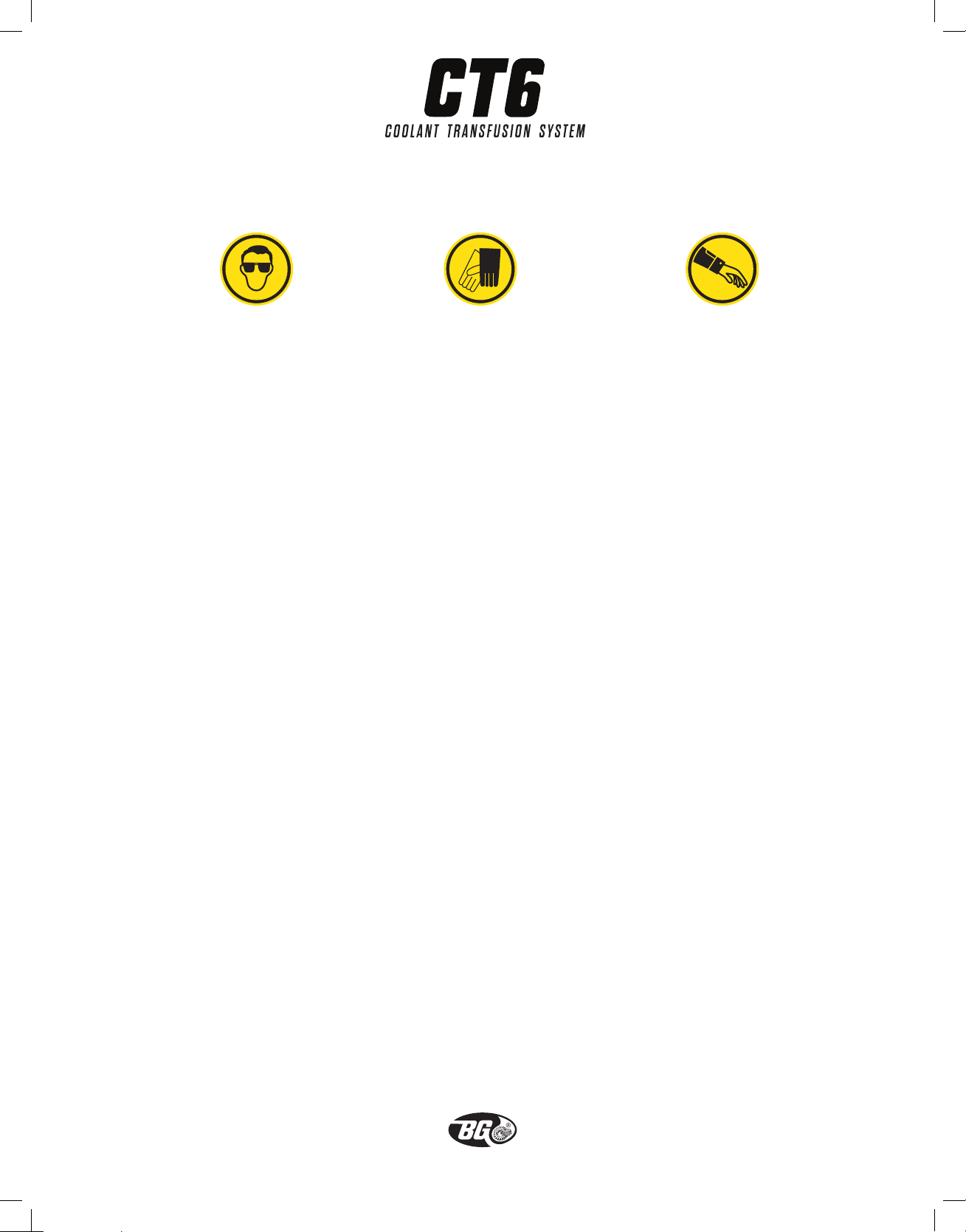
Wear safety goggles to
protect your eyes.
Wear Nitrile,® Neoprene®
or PVC gloves to protect
your hands.
Wear a long-sleeved shirt
and rubber or other
protective apron.
The following instructions must be followed before servicing or attempting to place this system into
operation and removing or adding fluid to any vehicle cooling system.
1. Carefully read the BG CT6 Reference Manual before beginning vehicle service.
2. Before handling any BG product, read its Safety Data Sheet.
3. A combination of mechanical and local ventilation should be used to prevent operator
exposure to noxious fumes.
4. This machine incorporates parts such as snap switches and receptacles that may produce arcs
or sparks and, therefore, when located in a garage, should be in a room or enclosure provided
for the purpose, or should be 18 inches (46 cm) or more above the floor.
5. Keep all hoses and tools away from moving engine parts.
6. Check all lines and adaptors for cracks and leaks before and after service.
7. Use EXTREME CAUTION when removing radiator cap to prevent being burned by hot fluid
escaping from the cooling system. Use EXTREME CAUTION when handling hoses and adaptors
on BG CT6 as they can reach the same temperature as coolant.
8. Ensure that the BG CT6 S1 pump switch is in the “Off” (O) position before connecting to power
source.
9. DO NOT dispose of any cooling system fluids or filters in a manner that is not in compliance
with federal, state or local environmental regulations.
The BG CT6 Coolant Transfusion System is designed to be used only with a vehicle cooling system
service. DO NOT use the BG CT6 to pump or transfer any flammable or combustible liquids.
5
Page 7
ORIGINAL INSTRUCTIONS ©copyright 2015 BG Products, Inc. • Wichita, Kansas 67213 • www.bgprod.com
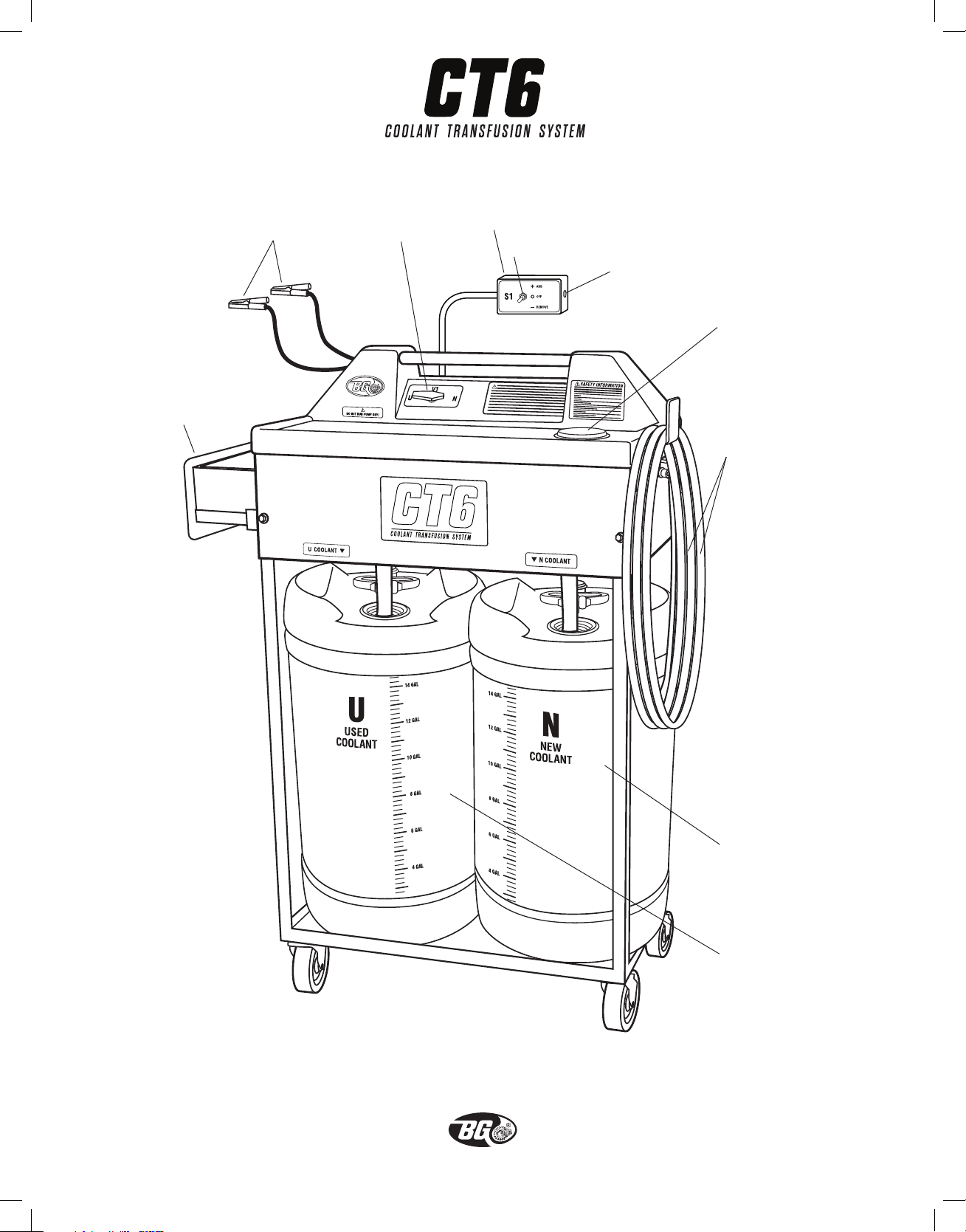
Storage drawer
Remote switch box assembly
Power cables
V1 control valve
S1 pump switch
Circuit breaker
Funnel
Service hoses (P and R)
N New coolant
container
U Used coolant
container
6
Page 8

ORIGINAL INSTRUCTIONS ©copyright 2015 BG Products, Inc. • Wichita, Kansas 67213 • www.bgprod.com
Preparing for Service
1. Attach the suction wand to the end of the pump hose (P).
2. Roll BG CT6 to the new (or recycled) 50/50 coolant supply. Be sure S1 pump switch is set to
“Off” (O).
3. Connect the power cables to a 12-volt battery or other 12-volt power source.
4. Insert the suction wand into the new coolant supply.
5. Turn V1 control valve to “N”.
6. Turn S1 pump switch to “Remove” (–). This will fill the BG CT6 new coolant (N) container.
7. Turn S1 pump switch to “Off” (O).
IMPORTANT! Do not run pump dry!
The BG CT6 can also be filled by pouring or pumping coolant (using an external pump) directly into
the funnel on top of the machine.
To empty the BG CT6 Used Coolant (U) container:
1. Attach the CT6 Waste Fluid Drain Hose to the waste fluid (W) port place the end of the hose into
a used coolant receptacle.
2. Attach an air line to the supply air (A) port.
3. Open the ball valve at the supply air (A) port.
4. When the used coolant (U) container is empty, close ball valve at the supply air (A) port
5. Disconnect air line from the the supply air (A) port.
NOTE: Filling the new coolant (N) container and emptying the used coolant (U) container can be
done simultaneously.
7
Page 9
ORIGINAL INSTRUCTIONS ©copyright 2015 BG Products, Inc. • Wichita, Kansas 67213 • www.bgprod.com
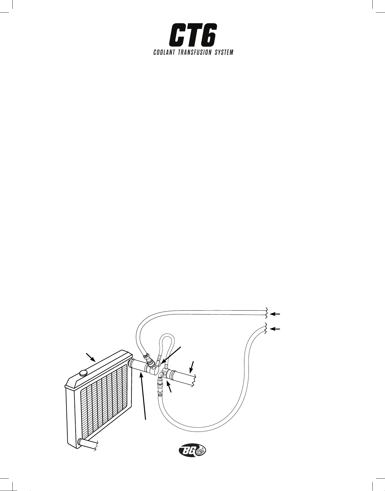
Installing BG Upper Radiator Hose Adaptor
CAUTION! To prevent being burned by hot fluid escaping from the cooling system, allow vehicle to
cool before removing radiator cap!
1. Remove radiator cap and insert the suction wand end of the pump hose (P) as deep into the
radiator as possible.
2. Turn V1 control valve to “U.”
3. Turn S1 pump switch to “Remove” (–). Remove enough used coolant to allow for a dry removal
of the upper radiator hose, then turn S1 pump switch to “Off” (O).
4. Move the suction wand to the radiator overflow tank.
5. Turn S1 pump switch to “Remove” (–) to remove all the used coolant from it.
6. Turn S1 pump switch to “Off” (O).
7. Clamp off the upper radiator hose about 4–6 inches (10–15 cm) from the end that connects to
the radiator. Remove the upper radiator hose from the radiator.
8. Determine the correct size adaptor and matching short hose/adaptor assembly needed for the
upper radiator hose. Screw the CT700 adaptors into the base unit—it makes no difference
which adaptor goes into which end. Put the loose clamp into place on the hose—do not tighten.
9. Install the CT700 adaptor between the radiator and upper radiator hose and tighten all clamps.
Be sure the ball valve on the connector hose is in the open position (handle parallel to the
hose).
Note: The CT700 is non–directional.
BG CT6 return hose (R)
BG CT6 pump hose (P)
Radiator
BG Upper Radiator Hose Adaptor
Short hose/adaptor
assembly
Ball valve
Upper radiator hose
PN CT700
8
Page 10

ORIGINAL INSTRUCTIONS ©copyright 2015 BG Products, Inc. • Wichita, Kansas 67213 • www.bgprod.com
BG Cooling System Service
PROCEDURE
1. Install one 12 oz. (355 mL) bottle of BG Universal Cooling System Cleaner, PN 540, into the
mouth of the radiator.
2. Insert the suction wand into the radiator.
3. Turn V1 control valve half way between “N” and “U”.
4. Turn S1 pump switch to “Add” (+).
5. Turn V1 control valve slowly to “U” to avoid splashing the coolant. Fill the radiator.
6. Turn S1 pump switch to “Off” (O).
7. Replace the radiator cap securely.
8. Start the engine and run at idle 10–15 minutes to circulate the BG Universal Cooling System
Cleaner.
9. Stop engine and remove the suction wand from the end of the pump hose (P).
Coolant Transfusion: Engine Off
Systems with thermostat connected to upper radiator hose:
1. Attach the pump hose (P) to the engine side of the CT700.
2. Attach the return hose (R) to the radiator side of the CT700.
3. Close the ball valve on the CT700.
4. Turn V1 control valve to “N”.
5. Turn S1 pump switch to “Add” (+).
Systems with thermostat connected to lower radiator hose
1. Attach the pump hose (P) to the radiator side of the CT700.
2. Attach the return hose (R) to the engine side of the CT700.
3. Close the ball valve on the CT700.
4. Pinch off the small tube that connects the radiator fill neck to the recovery tank. (Failure to
continued on next page
9
Page 11

ORIGINAL INSTRUCTIONS ©copyright 2015 BG Products, Inc. • Wichita, Kansas 67213 • www.bgprod.com
Procedure continued from previous page
pinch off this hose may allow the cap to vent coolant under pressure to the recovery tank causing it to fill and overflow.)
5. Turn V1 control valve to “N”.
6. Turn S1 pump switch to “Add” (+).
NOTE: If attempting to do service and the pump stops or flutters (turns off and on repeatedly),*
check for flow through the service hoses. If there is flow, the service will proceed without a problem. The fluttering can be stopped by moving the control valve towards the center position (do not
completely shut off flow). If there is no flow, check quick coupler connections and verify thermostat
location for proper flow direction.
*The BG CT6 system contains a pressure switch that is set to prevent over-pressurizing of the cool-
ing system. Motor will start again when pressure is released.
In the event that flow cannot be achieved with the engine off,
the service can be performed with the engine running.
Coolant Transfusion: Engine Running
1. Reverse the BG CT6 service hoses (P and R) at the BG CT700, so that the pump hose (P) is
attached to the side opposite the thermostat. The return hose (R) should be attached to the
thermostat side.
2. Open ball valve on BG CT700
3. Start engine and run until it reaches full operating temperature.
4. Close ball valve on BG CT700.
5. Turn V1 control valve to “N”.
6. Turn S1 pump switch to “Add” (+).
7. It will be necessary to pinch off the small hose to the recovery tank to prevent the radiator cap
from releasing coolant as the thermostat closes and opens. The pump motor will also likely
cycle on and off as pressure builds when the thermostat closes.
10
Page 12

ORIGINAL INSTRUCTIONS ©copyright 2015 BG Products, Inc. • Wichita, Kansas 67213 • www.bgprod.com
Removing the CT700 Upper Radiator Hose Adaptor
NOTE: Do not allow the BG CT6 new coolant (N) container to run dry—save enough coolant to
refill the overflow tank.
1. When transfusion is complete, turn S1 pump switch to “Off” (O).
2. Turn vehicle engine off.
3. Open the ball valve on the CT700 to release any trapped pressure from the engine.
4. Important! Allow the engine to cool before removing the radiator cap! Remove radiator cap.
5. Disconnect both service hoses (P and R) from the CT700.
6. Attach the suction wand to the pump hose (P) and insert the suction wand deep into the
radiator.
7. Turn V1 control valve to “N”.
8. Turn S1 pump switch to “Remove” (–). This will transfer the new coolant in the upper radiator
into the BG CT6 new coolant (N) container.
9. Remove the CT700 and reconnect the upper radiator hose securely.
®
10. Add BG Universal Super Cool,
PN 546, to radiator.
11. Place the suction wand back into the radiator.
12. Turn V1 control valve half way between “N” and “U”.
13. Turn S1 pump switch to “Add” (+).
14. Turn V1 control valve slowly to “U” to avoid splashing the coolant. Refill radiator with new
coolant.
15. Turn S1 pump switch to “Off” (O).
16. Replace radiator cap securely.
17. Move suction wand to overflow tank and fill to the normal level with new coolant.
11
Page 13
ORIGINAL INSTRUCTIONS ©copyright 2015 BG Products, Inc. • Wichita, Kansas 67213 • www.bgprod.com
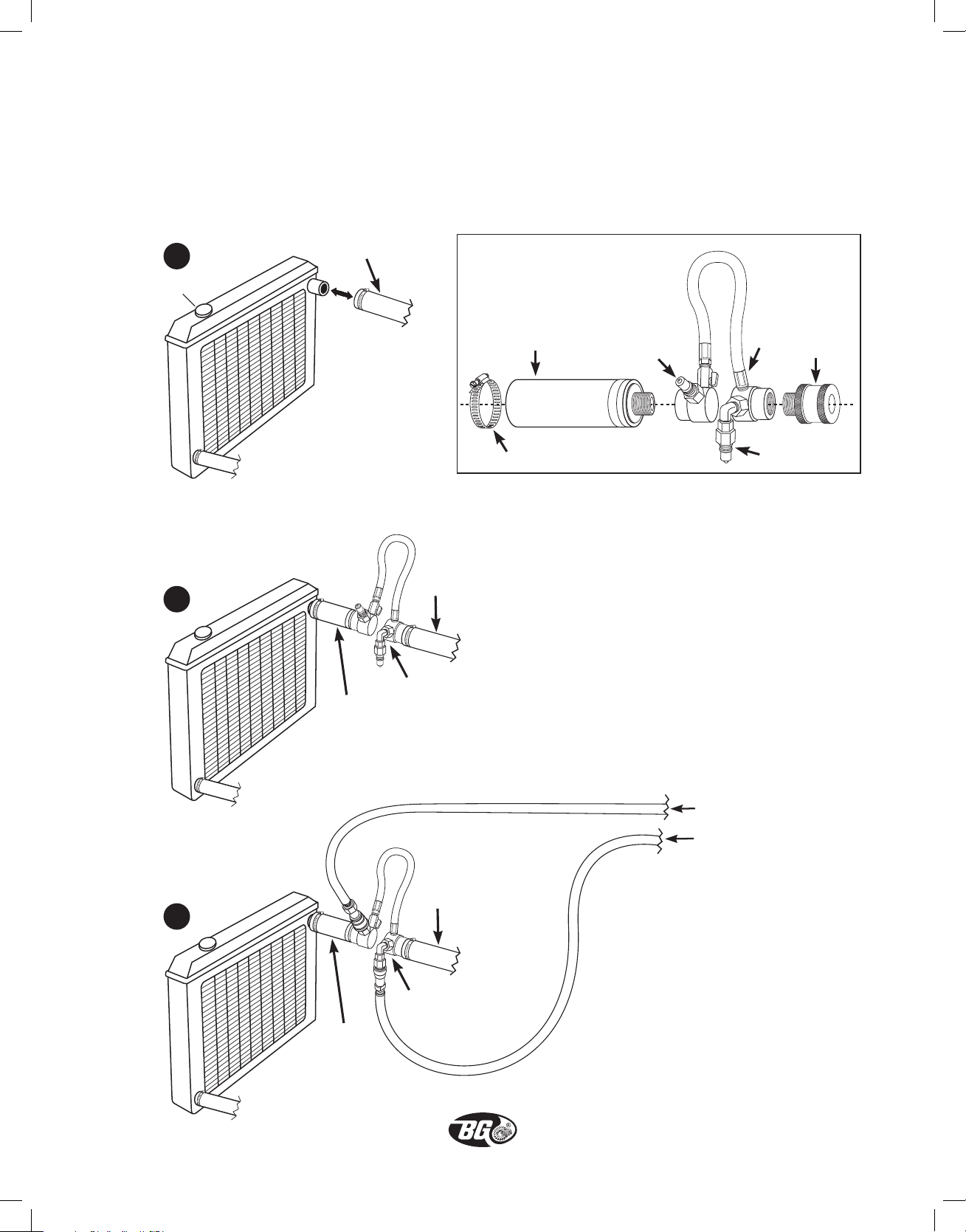
BG Upper Radiator Hose Adaptor Set
PN CT700
Installation
1
Radiator
2
Upper radiator hose
CT700 Assembly
Note: The CT700 is non-directional.
Upper radiator hose
Short hose/adaptor
assembly
Loose clamp
Quick connect
Ball
valve
Quick connect
Adaptor
3
Short hose/
adaptor
assembly
Short hose/
adaptor
assembly
CT700
BG CT2 return hose (R)
BG CT2 pump hose (P)
Upper radiator hose
CT700
12
Page 14
ORIGINAL INSTRUCTIONS ©copyright 2015 BG Products, Inc. • Wichita, Kansas 67213 • www.bgprod.com
H110-4
Garden hose seal
(#313 Buna O-ring)
CC718
Swivel adaptor
assembly
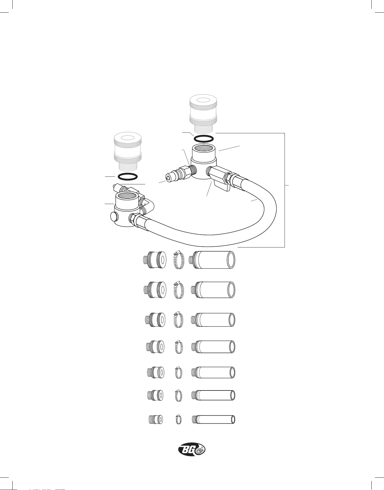
BG Upper Radiator Hose Adaptor Set
PN CT700
Parts List
H110-4
Garden hose seal
(#313 Buna O-ring)
BG27
1
Nipple,
/4˝ MNPT
1
x
/4˝ MNPT,
close length, brass
CC715
1
/4˝ male chrome
quick connect
Ball valve
x 3/8˝ FNPT, hex stock,
brass, chrome plated
BG25
3
/8˝ MNPT
CC719
Adaptor body
CT707
Hose
assembly
for CT728
CT728
CT700 female
body assembly
only for CT2
CC732
1
/4˝ adaptor
2
CC725
2˝ adaptor
CC724
3
1
/4˝ adaptor
CC723
1
1
/2˝ adaptor
CC722
3
/8˝ adaptor
1
CC721
1
/4˝ adaptor
1
CC720
1˝ adaptor
CC733
1
/4˝ x 4˝ radiator hose
2
CC704
2˝ x 4˝ radiator hose
CC727
3
1
/4˝ x 4˝ radiator hose
CC703
1
1
/2˝ x 4˝ radiator hose
CC726
3
/8˝ x 4˝ radiator hose
1
CC702
1
1
/4˝ x 4˝ radiator hose
CC701
1˝ x 4˝ radiator hose
13
Page 15
ORIGINAL INSTRUCTIONS ©copyright 2015 BG Products, Inc. • Wichita, Kansas 67213 • www.bgprod.com
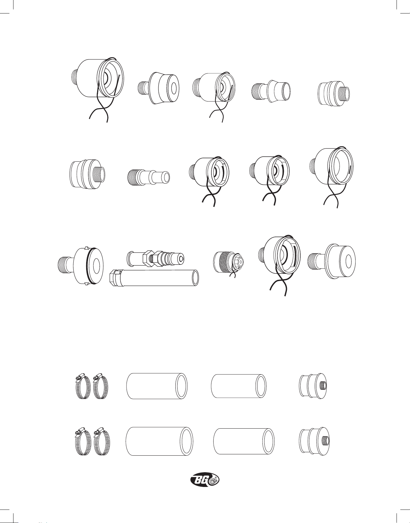
(2 each)
Optional Upper Radiator Hose Adaptors
991-017
Ford 6.4 radiator
adaptor, female
CC730
BMW & VW radiator adaptor
(mates w/CC735)
991-023
Mercedes radiator
adaptor, male
991-018
Ford 6.4 radiator
adaptor, male
CC731
5
/8˝ & 3/4˝ adaptor
CT2-017
3
/4˝ remote coolant
tank adaptor
991-020
Ford Focus radiator
adaptor, female
CC734
VW radiator
adaptor, female
991-025
Audi/Ford expansion
tank adaptor
991-021
Ford Focus radiator
adaptor, male
CC735
BMW & VW radiator
adaptor, female
991-029
Ford 6.7L coolant
adaptor, female
CC729
VW radiator adaptor
(mates w/CC734)
991-022
Mercedes radiator
adaptor, female
991-030
Ford 6.7L coolant
adaptor, male
Large Capacity Upper Radiator Hose Adaptor Set
PN CT6-100
CC738
3
2
/4˝ x 6˝ radiator hose
CC741
1
3
/2˝ x 6˝ radiator hose
14
2 1/2˝ x 6˝ radiator hose
CC737
CC740
3˝ x 6˝ radiator hose
1
2
CC736
/2˝, 2 3/4˝ radiator adaptor
(2 each)
CC739
3˝, 31/2˝ radiator adaptor
Page 16
Page 17
Scan this code or visit
http://bgfor.me/ct6ref
to access instructions
in other languages and
additional information.
This code can also be
found on the serial plate
on the back of the BG CT6.
•
XV
V
©Copyright 2014 BG Products, Inc. • Wichita, Kansas 67213 • MADE IN U.S.A. • PN CT6-070
 Loading...