

Page 1
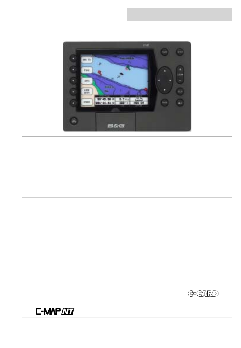
cnd
introduction
overview
Congratulations on your purchase of the Central Navigation Display (CND) from B& G. The CND i s
the latest in chart plotting and navigation displays from B&G and represents B&G’s commitment to
providing customers the finest marine navigation systems. The CND is a state-of-the-art
computerised electronic chart system designed as a sophisticated navigation aid. Your CND
provides many useful feat ures and is easy to use.
Before you begin using your new CND, please take the time to read this manual to help you
achieve the full potential
from your new system.
features
All calculations and information necessary for navigation are performed and displayed on the
screen quickly and accurately providing all of the facilities of a conventional GPS but with the
added benefit of a powerful electronic chart display.
Features
The Central Navigation Displ ay (CND) i s a f ully f unct ioned c olour Chart Plot ter which c an be us ed
either as a stand-alone syst em or integrated into an instrument system.
• Daylight viewable transflective ¼ VGA colour screen gi ves excellent clarity even in bright
sunlight
• Latest presentation of C-Map NT Cartography, hot-swap cartridges
• Highest specification C-Map NT feature implement at i on
• Utilises C-Map User-Card technology to enable backup of waypoints, tracks, routes and
marks. Also can be used for home route planning (with opti onal C-Map PC-P l anner Kit)
Instrumentation data repeater - any NMEA instrument source (see “Interfacing” for details),
custom pages provide eas y to use presentation of inst rument data.
User information lik e Waypoints, Mark s and tracks can be stored on a User
can be recalled at any tim e. The CND will also display available instrument data in dedicated
display formats. On the screen are shown navigati on data and cartographic informat ion obtained
from
03/09/01 Page 1
electronic charts.
, and
Page 2
introduction
certification
cnd
warnings & precautions
WARNING:
The GPS system is operated by the United St ates government , which is solely responsi ble for its
accuracy & m aintenance. The s ystem is subjec t to changes that could aff ect the accuracy and
performance of all GPS equi pment. Alt hough the B&G CND is a precision electroni c NAVigati on
AID (NAVAID), any NAV A ID can be misused or m i sinterpreted and, therefore, become unsafe.
Use the CND at your own risk. To reduce the risk of unsafe operation, carefully review and
understand all aspects of this Owner’s Manual – and thoroughly practice operation using the
simulator m ode prior to actual use. When in ac tual use, carefully com pare indications from t he
CND to all available navigation resourc es, including the informat ion from other NAVAIDs, visual
sightings, charts , etc. For safety, always res ol ve any discrepancies before continui ng navi gation.
CAUTION:
The unit meets the requirements of IP67 sealing, only when the door is closed.
Do not use an alcohol based cleaner on this display.
Note:
This equipment generates, uses, and can radi ate radio frequency energy and, i f not instal led and
used in accordance with the instructions, may cause harmful interference to radio
communications . However, there is no guarantee that interferenc e will not occur in a particular
installation. If this equipment does cause harm ful interference, the user is encouraged to try to
correct the interf erence by relocating the equipment or connecting the equi pment to a different
circuit. Consult an authorised dealer or other qualified technician for additional help if these
remedies do not
This device meets requi rements for CFR47 Part 15 of the FCC l i mits for Class B equi pment.
The CND meet s the standards set out in E uropean Standard EN 60945: 1997 IEC 945 : 1996 for
maritime navigati on and radi ocommunication equi pment and systems .
The CND contains no user-serviceabl e parts. Repairs should only be made by an authorised
service centre. Unauthorised repairs or modifications will void your warranty.
correct the problem.
trademarks
All rights reserved. No part of this manual may be reproduced or transmitted in any form or by any
means including photocopying and recording, for any purpose without the express written
permission of B& G.
Information in this document is subject to change without notice. B&G reserves the right to
change or improve its products and to make changes in the content without obligation to notify any
person or organisation of such changes.
B&G, Central Navigation Dis play, CND are all trademarks of Brookes & Gatehouse Ltd and may
not be used without the express permission of B&G.
C-MAP, C-MAPNT and CF-95 are all trademarks of C-MAP Ital y srl and may not be used without
the express permission of C-MAP.
Page 2 03/09/01
Page 3

cnd
Overview 1
Features 1
Features 1
Certification 2
Warnings & Precautions 2
Trademarks 2
Display overview 6
Switching on and off 7
Switching On 7
Switching Off 7
Backlight 7
C-CARD 8
Inserting the Card 8
Removing the card 8
System settings 8
Overview of the display 9
Navigate to a single destination 9
Distance to bearing 9
Steer 9
Deleting a Destination 9
Navigating on a route 10
Adding a Waypoint 10
Creating a route 10
Deleting a waypoint 10
Moving Waypoint 11
Inserting a Waypoint 11
Editing Waypoints 12
Finding information 13
Time To Go 13
C-MAPNT Information 13
Getting Quick Information 13
Getting Port Information 14
Getting Tid al Information 15
Finding Port Services. 16
Finding Port by Name 18
Searching by name 18
Searching by list 19
Finding Tide Stations 20
Data pages 21
Speed/Depth 21
Navigation 22
Wind 22
Multi Function 23
Data Logs 24
contents
contents
03/09/01 Page 3
Page 4

contents
contents
GPS mode 25
GPS Mode 25
Status Page 25
GPS Page 25
Road Page 26
XTE Page 26
XTE Options 26
Routes 27
Main Setup Screen 27
Selecting a route 27
Selecting a route to work 27
Deleting a route 28
Route Colour selection 28
Reversing a route 28
Route Report 29
Changing Speed & Fuel values 29
Route Report from the chart. 30
Finding information on Waypoints 30
Deleting a Waypoint from the list 31
Viewing Waypoint/Marks in a Route list 31
Finding a Waypoint/Mark on the chart 32
Marks 33
Adding a Mark 33
Converting a MARK to a Waypoint 33
Deleting a Mark 33
Man Over Board 33
Setup menu 34
Selecting Alarms 34
Depth – Shallow Water Alarm 34
Depth – Deep Water Alarm 34
Anchor drag alarm 34
HDOP Alarm 34
Cross Track Alarm 34
Waypoint Arrival Alarm 34
Selecting System Settings 35
To set the Language 35
To set the GPS/NMEA 35
To set the Units 36
Selecting Chart Plotter settings 36
To set the Display Options 1 37
To set the Display Options 2 37
Selecting Demo Mode settings 37
Selecting About 38
Position correction 38
Position Correction 38
cnd
Page 4 03/09/01
Page 5

cnd
Track functions 39
Track functions 39
Enabling Track Storing 39
Selecting Active Track 39
Displaying Track 39
Selecting Track Colour 39
Selecting Time Interval 40
Selecting Vector 40
Delete Current Track 40
Memory menu 41
Memory Menu 41
Saving a File 41
User C-CARD menu 42
Loading a File 42
Deleting a File 42
Sort the User C-CARD Directory 42
Reading the User C-CARD 42
Selecting slot 42
Formatting User C-CARD 43
Technical Specifications 44
Installation 45
Precautions 45
Panel mounting 45
Electrical Connections 45
Electrical Connection 45
Power/Data 46
NMEA In (Instrument Interface) 46
Fastnet2 46
Terms and functions 47
Troubleshooting 58
Warranty 59
contents
contents
03/09/01 Page 5
Page 6
getting started
display overview
cnd
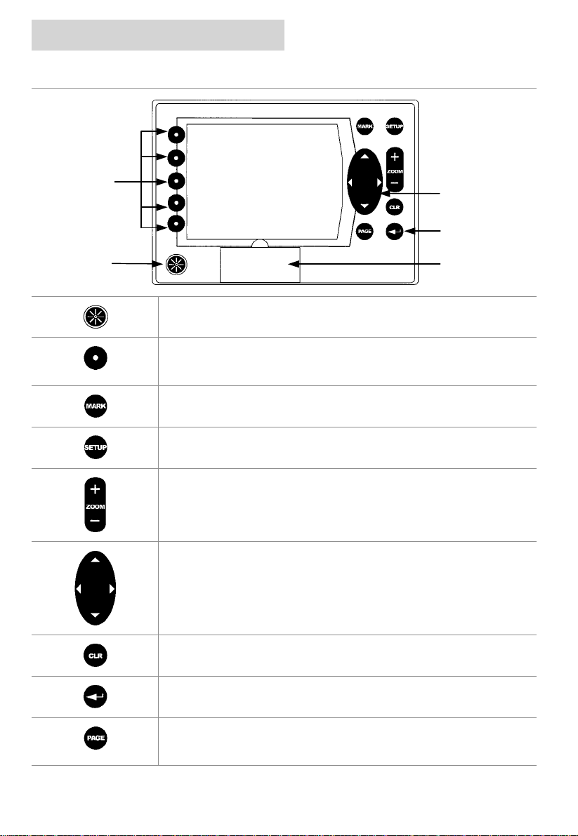
Softkeys
PWR key
Press the PWR key to turn the CND On
There are 5 Softkeys, which have different functions when you select
different modes of operation, the labels for the current functions are
shown on the screen immedi ately adjacent to the keys.
Press the MARK key to place a Mark at your boat’s current position.
Press the SETUP key to enter the Setup pages .
Press the ZOOM + key to display more details of a smaller area, by
changing the chart scale and zooming in on your display. Press the
ZOOM – key to change the sc ale and display a wider view.
CURSOR
ENTER
C-MAP Cover
The CURSOR keypad moves the curs or about on the display screen,
quickly and accurately. It also scrolls the desired option in the menu
page(s).
Press the CLR key to exit from m enu or t o leave a m enu without m aki ng
changes.
Press the ENTER key to select a func tion or enter a waypoint.
Press the PAGE key to scroll through the three different s ets of pages:
Page 6 03/09/01
Data (Speed & Depth, Nav, W ind, Multi)GPS (Status, Position, Road,
XTE), and Chart Plotter.
Page 7
cnd
getting started
switching on and off
Before turning the CND on, check that the
installation instructions in Appendix B have
been correctly followed.
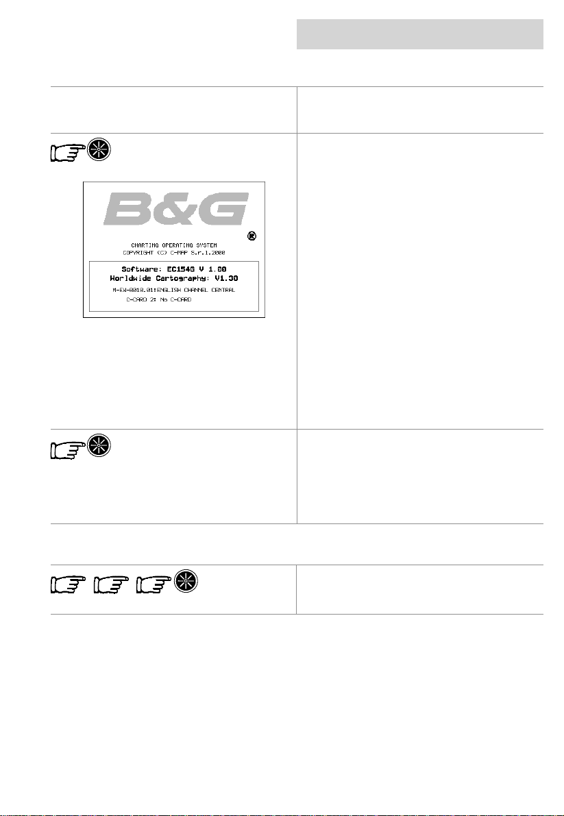
Switching On
Pressing the PWR key for one second switches
on the CND, you will first be presented with the
B&G logo screen and software version
information.
The CND will then perform a short self test
procedure that checks internal memory and
displays any failure detected on the screen.
If installed, the C-CARD will also be tested.
After a few seconds, a Caution page is
displayed, reminding you that the chart plotter
is only an aid to navigation, and should be used
in conjunction with normal navigational
practices.
Pressing any key will then display the
cartographic screen with a position if an
external GPS is connected.
The display can be customised for your
personal preferences using the System
Settings section.
Switching Off
Press the PWR key and hold for three
seconds, a countdown timer appears on the
screen, when this reaches zero it will power off.
If you release the key before the countdown
timer reaches zero, the CND will remain on.
backlight
There are three levels of backlight ing. To alter
the level of backlighting, press and release the
PWR key until the desired l evel .
03/09/01 Page 7
Page 8
getting started
c-card
cnd
The CND uses two types of C-MAPNT
cartridges,
The C-CARD, contains detailed charts of the
area covered.
The User C-CARD can be used t o perm anently
store your routes, Waypoints, Marks and
tracks.
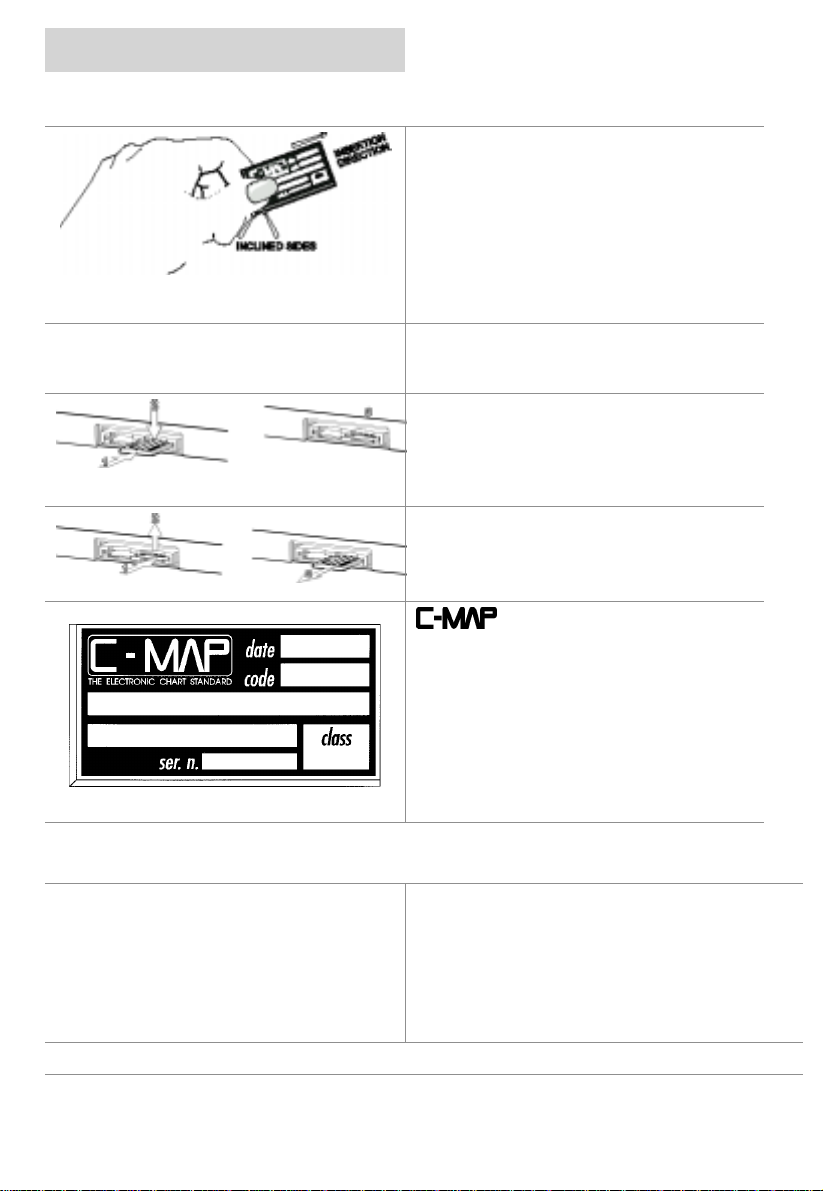
Hold the C-CARD by the short inclined side s o
that you can see the C-MAP label.
WARNING
ensure C-Card door area is dry. Failure to
comply may result in invalidation of warranty.
Inserting the Card
Gently push the C-CA RD into one of the slots
(1), push the C-CARD in as far as it will go,
then gently move it to the bot tom pos it ion (2) to
hold it in the slot (3).
Removing the card
Press the C-CARD gentl y inward (1) and move
it upwards (2) until you hear a click, the
C-CARD will then eject out of the slot (3).
: To prevent ingress of water,
and revising old ones. If you wish to receive
information on the newest availabl e charts , you
can write for a catalogue of available charts or
ask at your dealer.
is continuously c reating new charts
system settings
Keypad Beep: On
Language: English
Speed/Distance Units : Nautical Miles
Depth Units: Metres
Wind Speed Units : Knot s
To change any of these settings, please refer to the System Settings section.
Bearing Reference: Magnetic
Date Format: Day-Month-Year
Time Reference: UTC
Coordinate System: degrees and
minutes (2 dec. places)
Page 8 03/09/01
Page 9
cnd
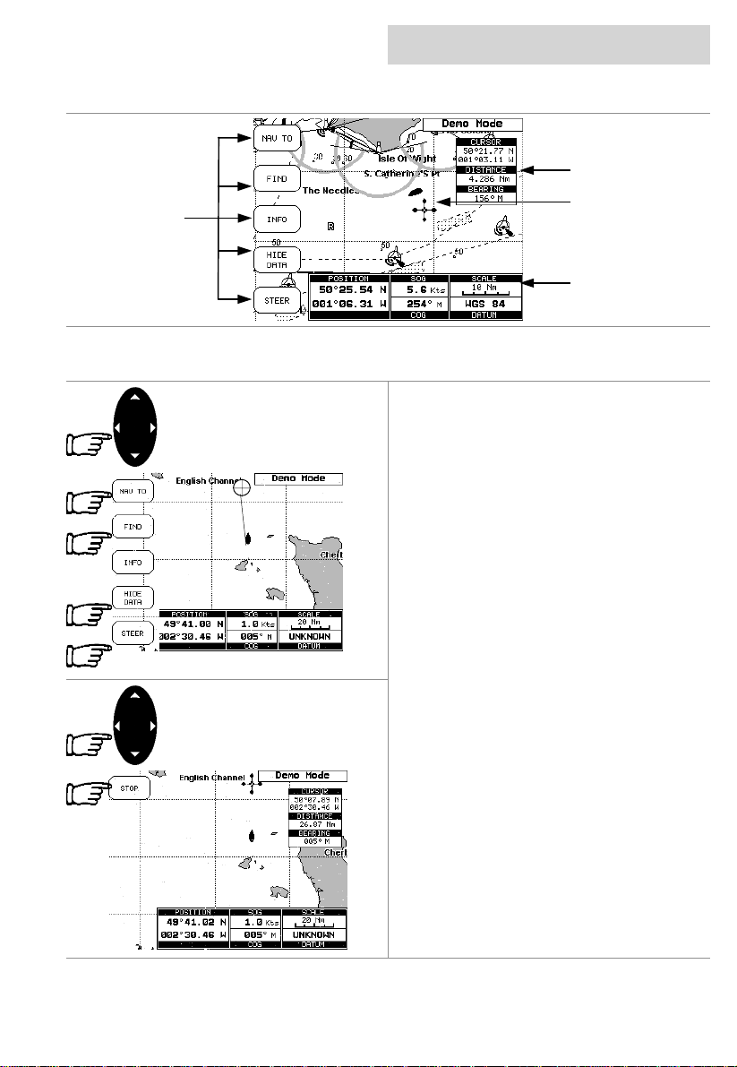
Softkeys
Label
getting started
overview of the display
Cursor Box
Cursor
Text Box
navigate to a single destination
Using the CURSOR keypad move the curs or to
your desired destination then press the
NAV TO softkey, t his softkey will then change
to the START softkey, pressing the START
softkey will then create the Direct Target.
A line is drawn connecting the Direct Target
symbol with the boat’s position, all navigation
data is now referred to this Target.
Distance to bearing
Position the c urs or on the Direc t Target sym bol
and the Cursor information box will contain the
Latitude/Longitude, the distance and the
bearing from your boat’s position.
Steer
Pressing the STEER Softkey will display the
Destination text box in place of the Position text
box.
Hide Data
Pressing the HIDE DATA Softkey will remove
the information box and display a full screen
chart and the softkeys.
Deleting a Destination
Using the CURSOR keypad to plac e the cursor
on the Direct Target symbol, the softkey will
then change to the STOP softkey, press the
STOP softkey and the Direct Target symbol
disappears from the screen.
03/09/01 Page 9
Page 10
getting started
cnd
navigating on a route
If you prefer to navigate following a route
towards its end point , you can define a series
of locations (Waypoints) in sequence to make a
route.
Adding a Waypoint
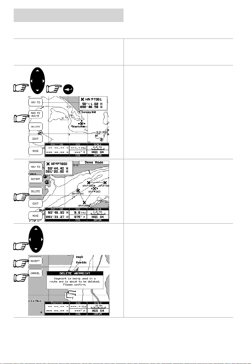
Using the CURSOR keypad place the cursor
on the desired position, pressing the ENTER
key will insert a Waypoint symbol on the chart,
press the ADD TO ROUTE Softkey to make it
the first point on your route.
Viewing Information on Waypoints
Position the cursor on the Waypoint and the
Cursor information box will change to the
Waypoint information box displaying the
Waypoint name and Latitude/Longitude.
Creating a route
Repeat the “Adding a Waypoint” procedure as
shown above until you reach your final
destination. The lines connecting the
Waypoints are known as a leg, a circle
surrounding the first Waypoint of the route
identifies the starting point.
Deleting a waypoint
Using the CURSOR keypad place the cursor
on the Waypoint to be deleted and press the
Page 10 03/09/01
DELETE Softkey, a window opens to advise
that the Waypoint is being used in a route,
press the ACCEPT Softkey to delete it, the
Waypoint is deleted and a new line between
previous and next Waypoint is shown.
Pressing the CANCEL Softkey returns to the
chart.
Page 11
cnd
getting started
navigating on a route
Moving Waypoint
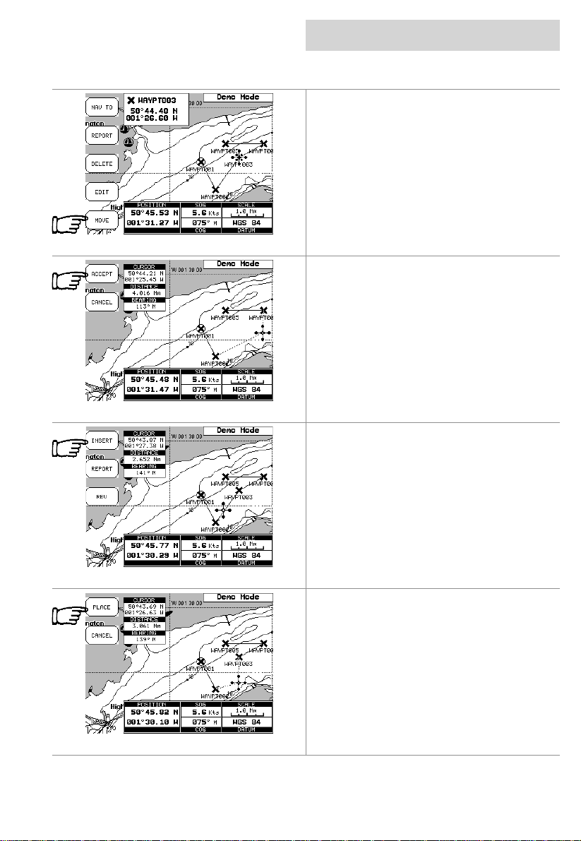
Place the cursor on the Waypoint and press the
MOVE Softkey, using the CURSOR keypad
move the Waypoint, a dotted line connecting
the Waypoint to the new position, is shown.
To place the Waypoint in the new position,
press the ACCEPT Softkey.
Inserting a Waypoint
Place the cursor on the route leg and press the
INSERT Softkey.
The line between the two Waypoints i s turned
into a dotted line (rubber-band), now move the
cursor to the new position.
Once you have positioned the cursor at new
location, press the PLACE Softkey.
03/09/01 Page 11
Page 12
getting started
navigating on a route
cnd
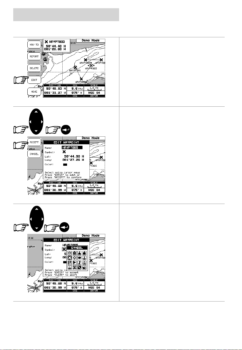
Editing Waypoints
Move the cursor onto the W aypoint and press
the EDIT Softkey
Use the CURSOR keypad to select the field
and press the ENTER key.
To enter a name use the CURSOR keypad to
insert the charact ers, then press the ACCEPT
Softkey.
To change the Symbol, use the CURSOR
keypad to select the Icon and press the ENTER
key.
If the Coordinates field is selected, press the
ENTER key and then use the CURSOR keypad
to insert the value.
If the Colour field is selected, pressing the
ENTER key will display a window with 8
different colour, use the CURSOR keypad to
select the desired colour and press the ENTER
key.
Then press the ACCEPT Softkey.
Page 12 03/09/01
Page 13
cnd
getting started
finding information
Time To Go
TTG value is displayed on the Display Page,
available by pressing the PAGE key twice and
the XTE Softkey.
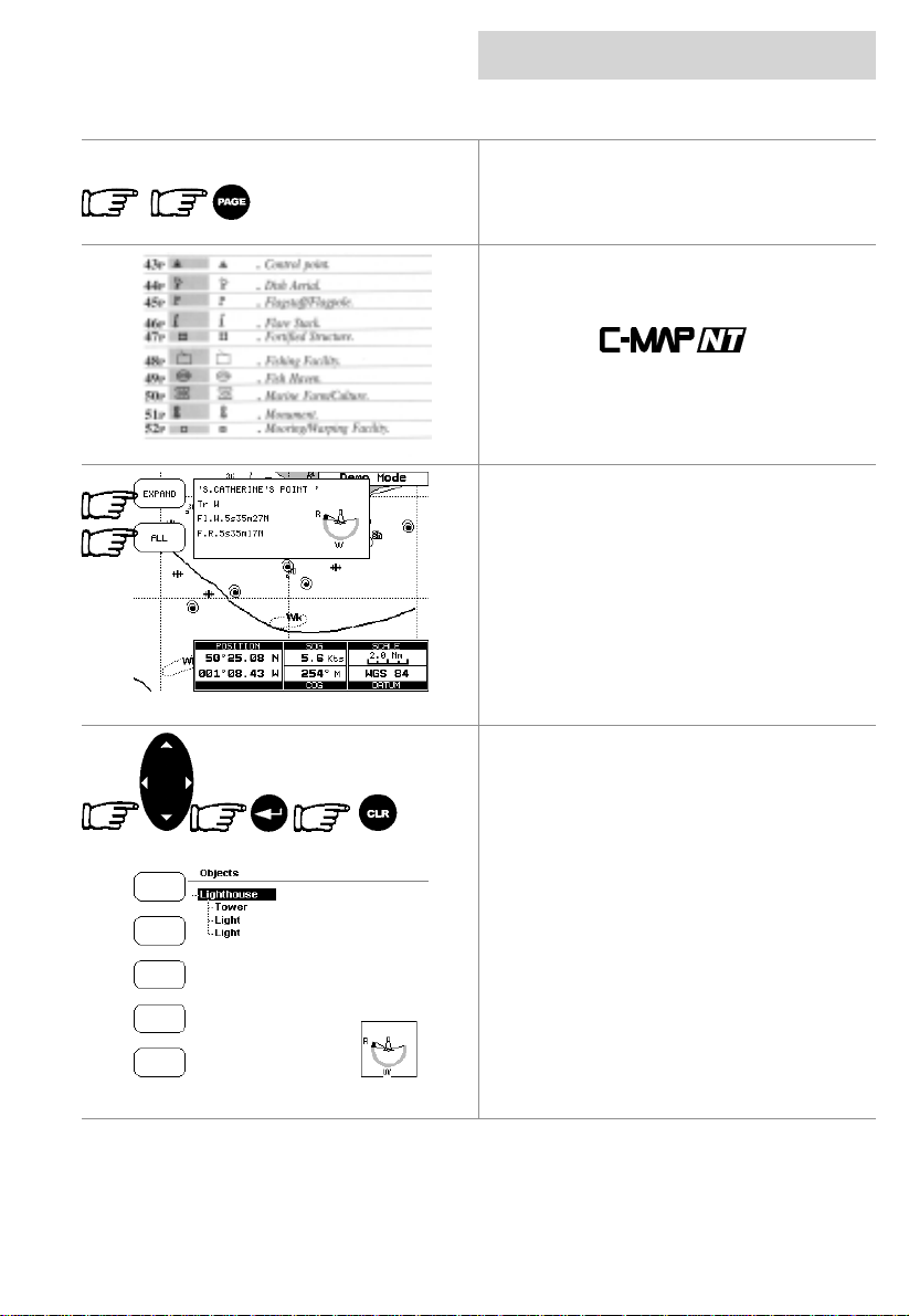
C-MAPNT Information
On the display you will see a variety of Icons
and symbols.
Refer to the
their explanation (example shown).
Getting Quick Information
Place the curs or on a chart symbol suc h as a
Nav-Aid, Wreck, etc. and a special pop-up
window is displayed. This feat ure called “Quick
Info” identifies the symbol and displays the
information about Nav-Aids.
To expand information about that object press
the EXPAND Softkey.
Pressing the ALL Softkey displays all availabl e
information about that cartographic point.
Use the CURSOR keypad to scroll through the
list, press the ENTER key to expand, If the
information is in several pages use the
CURSOR keypad to scroll through the fol l owing
pages.
To return to the previous page and t o exit press
the CLR key.
At the bottom right hand corner a window
displays the select ed obj ects icon.
Handbook for
03/09/01 Page 13
Page 14

getting started
finding information
Port Info
Icon
cnd
By pressing the INFO softk ey while the chart is
displayed will display a list of all objects f ound
in the range of the cursor.
If there are complex objects you will also find a
list of the com ponent s.
Use the CURSOR keypad to scroll through the
list, press the ENTER key to expand
Getting Port Information
When viewing the chart of a port or harbour,
you will see a Port Info icon, placing the cursor
on the symbol will display the available
information.
The Port Info symbol i s visible only if the Ports
+ Services option is On (defaul t setting).
Information is displayed with icons of the
available services.
Ensure the Info Level setting is detailed (default
setting).
To expand the information about t he port press
the EXPAND Softkey, to display all available
information for that cartographic point press the
ALL Softkey.
Page 14 03/09/01
Page 15
cnd
getting started
finding information
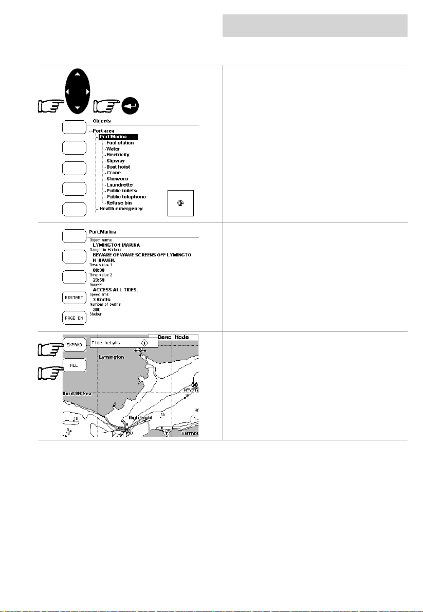
Select the service us ing the CURSOR keypad
and then press the ENTER key.
Detailed information on the services (opening
and closing tim e of the Fuel stat ion, telephone
number of local amenities, etc) are displayed.
This is available for all countries, where such
information exists on the paper chart.You will
also see accurately positioned symbols that
show where many useful facilities are located.
Getting Tidal Information
Some charts display a Tidal Diamond symbol
“T”, placing the cursor on the Tide symbol
displays the available inform ation in the Quick
Information window.
To display the Tide Graph page press the
EXPAND Softkey.
Pressing the ALL Soft key selects all available
information.
03/09/01 Page 15
Page 16
getting started
finding information
cnd
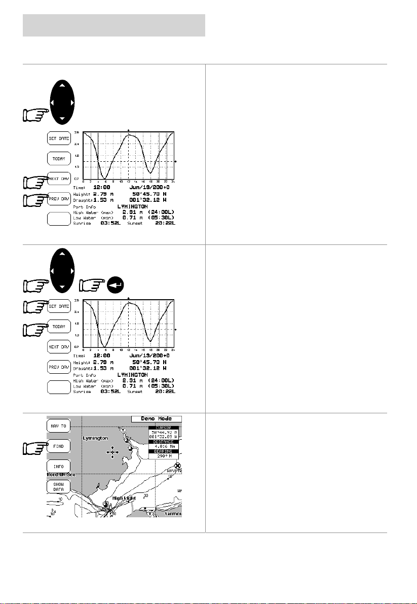
The screen will display today’s Tide Height
graph for the area where the Tidal symbol was
located.
The CND displays a moveable Vertical and
Horizontal slider. Using the CURSOR k eypad,
move the horizontal slider to correspond with
the draft of your boat.
Using the Vertical sl ider you can then read the
times at which the graph dips below the
horizontal line i.e. the times when you will be in
danger of grounding.
Pressing the NEXT DAY or PREV DAY
Softkeys displ ays future or past tides.
Pressing the SETDATE softkey and entering
the required date using the CURSOR keypad,
followed by the ENTER key displays the tide for
that date.
Pressing the TODAY softkey returns to the
current day’s tide graph
Note
Tide graphs are an approximation of the tide
and they should be used in conjunction with
traditional tide tables and navigational
methods.
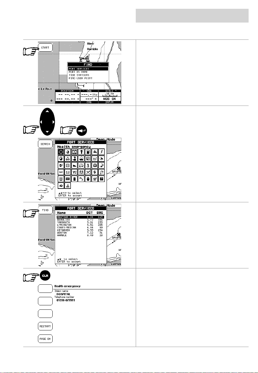
Finding Port Services.
Press the FIND Softkey.
Page 16 03/09/01
Page 17
cnd
getting started
finding information
When the find display appears press the
START
available facilities (i.e. the nearest Hos pit al, sail
maker, bank, etc .).
The icons list is shown of the available
services.
Select the facility using the CURSOR keypad
and then press the ENTER key. Displ ayed is a
list of ports nearest (up to 10) in which this
facility is present.
Choose the port you want and press the FIND
Softkey.
Softkey to displays the nearest
A list of that particular facility at the port is
displayed.
Pressing the CLR key returns to the chart with
the cursor located on the chosen facility.
03/09/01 Page 17
Page 18
getting started
finding information
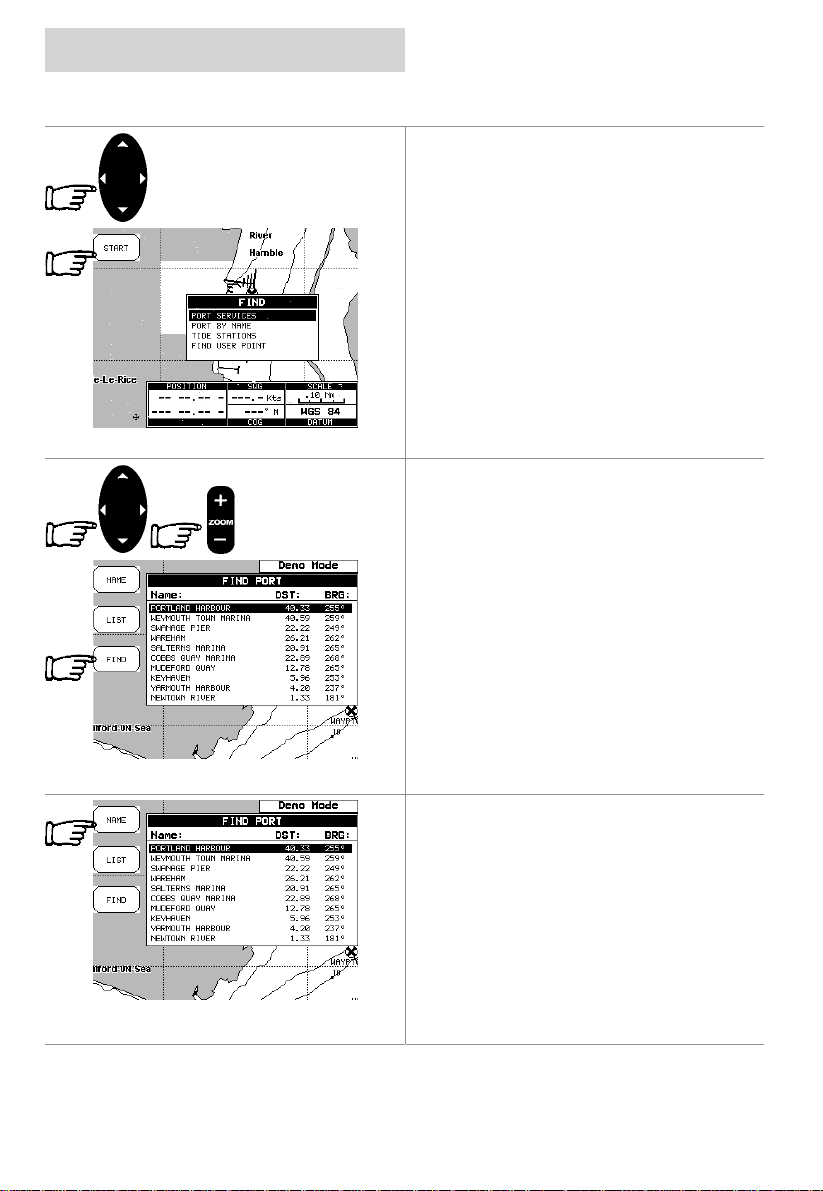
Finding Port by Name
Pressing the FIND Softkey displays the find
screen.
Using the CURSOR keypad select “Find Port
by Name” and press the
display a list of all port s stored on the C-CARD.
Use the CURSOR keypad to select the port
and the ZOOM +/- key to select next/previous
page.
Pressing the FIND Softkey to locate the
selected port on the chart.
Note
A Warning message is shown if there is no
C-CARD inserted or there are no ports on the
C-CARD.
START
cnd
Softkey to
Searching by name
Go to the “Find Port by Name” screen as
above, and press the NAME Softkey
Page 18 03/09/01
Page 19
cnd
getting started
finding information
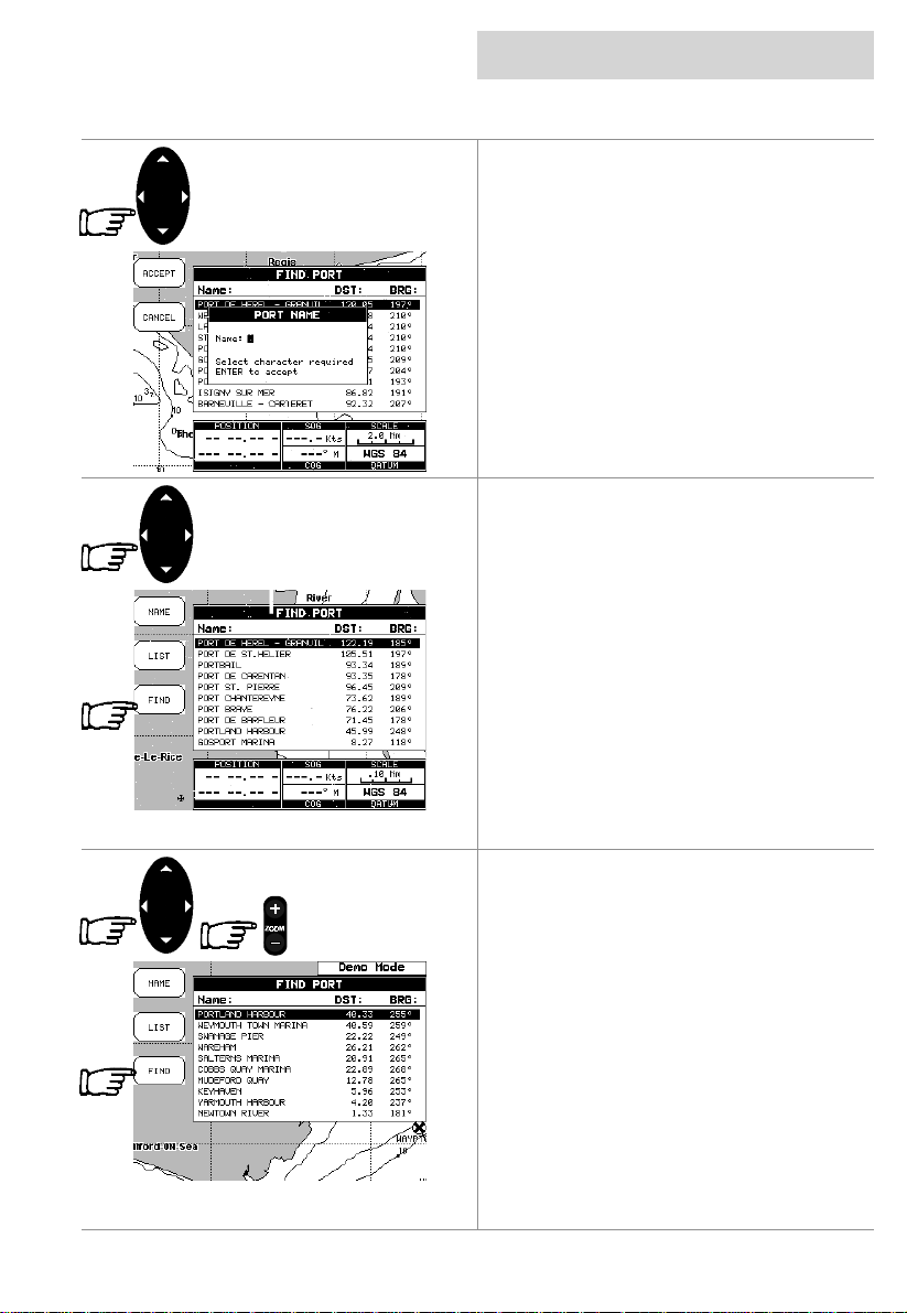
Insert the port name (m ax 15 characters ) using
the Up and Down CURSOR keypad to scroll
through the letters, pressing the right arrow
CURSOR keypad to move to the following
space.
A list of all ports containing the inserted name
is displayed. Repeat the operation to ref ine the
search or move through the list with the
CURSOR keypad.
Pressing the FIND Softkey locates the selected
port on the chart.
Note
A Warning message is shown when the
inserted name is not in the ports list.
Searching by list
Go to the “Find Port by Name” screen as
above.
Use the CURSOR keypad to select the port,
and using the ZOOM +/- key to select
next/previous pages.
Press the FIND Softkey to locate the selected
port on the chart.
03/09/01 Page 19
Page 20
getting started
finding information
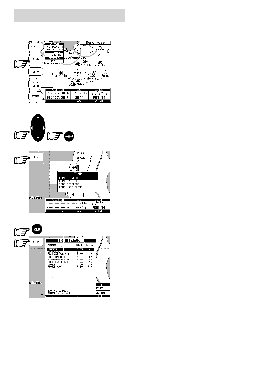
Finding Tide Stations
To find the nearest Tide Stat ions on the chart
press the FIND Softkey to display the find
screen.
Note
The find will be from the cursor position if the
fix position is not suitabl e.
Using the CURSOR keypad select Tide
Stations and press the
display a list of nearest Tide Stations (up to
10).
START
cnd
Softkey to
Choose the Tide Station you want and press
Page 20 03/09/01
the FIND Softkey to display the Tide Graph
page.
Pressing the CLR key returns to the chart to
display the Tide Station chosen.
Page 21
cnd
getting started
data pages
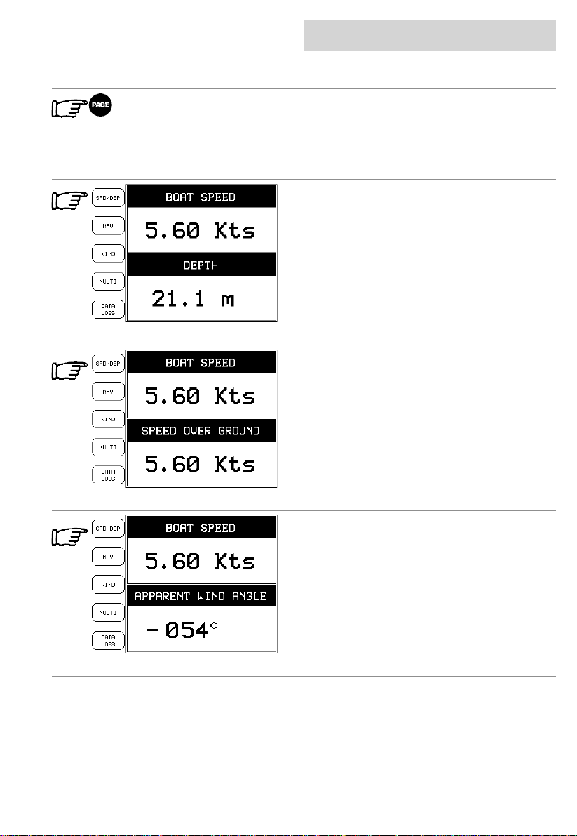
The Data Pages display the information
obtained from the other instruments on your
system. Using the information available,
various other parameters can be calculated
and displayed.
Press the PAGE key to enter the Data Pages.
Speed/Depth
The Speed and Depth displays are divided into
three pages, acc essed by repeatedly pressing
the SPD/DEP Softkey.
03/09/01 Page 21
Page 22
getting started
data pages
cnd
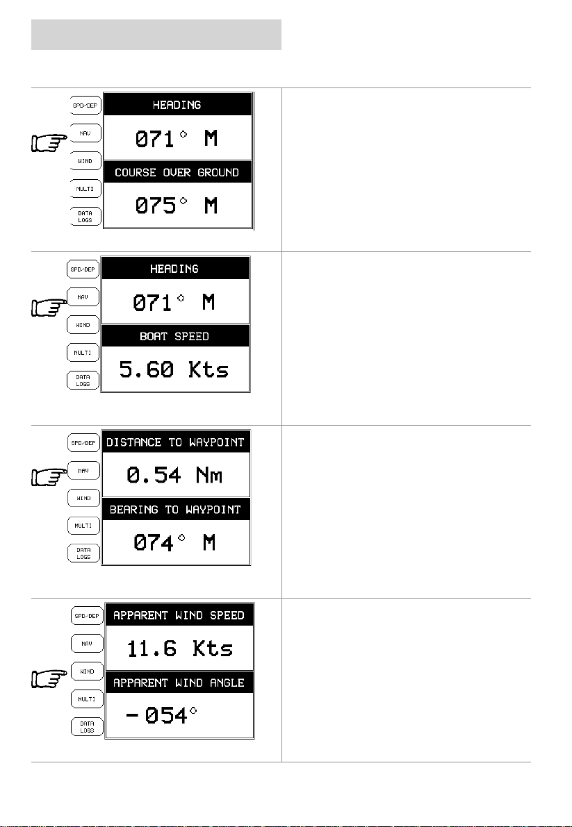
Navigation
The Navigation displays are divi ded into three
pages, accessed by repeatedly pressing the
NAV Softkey.
To scroll between pages press the NAV
Softkey.
Wind
The Wind displays are divided into three pages,
accessed by repeatedly pressing the WIND
Softkey
To scroll between pages press the WIND
Softkey
Page 22 03/09/01
Page 23
cnd
getting started
data pages
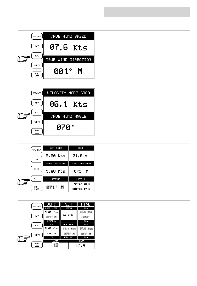
Multi Function
The Multifunction dis plays are divided into two
pages, accessed by repeatedly pressing the
MULTI Softkey.
03/09/01 Page 23
Page 24
getting started
data pages
cnd
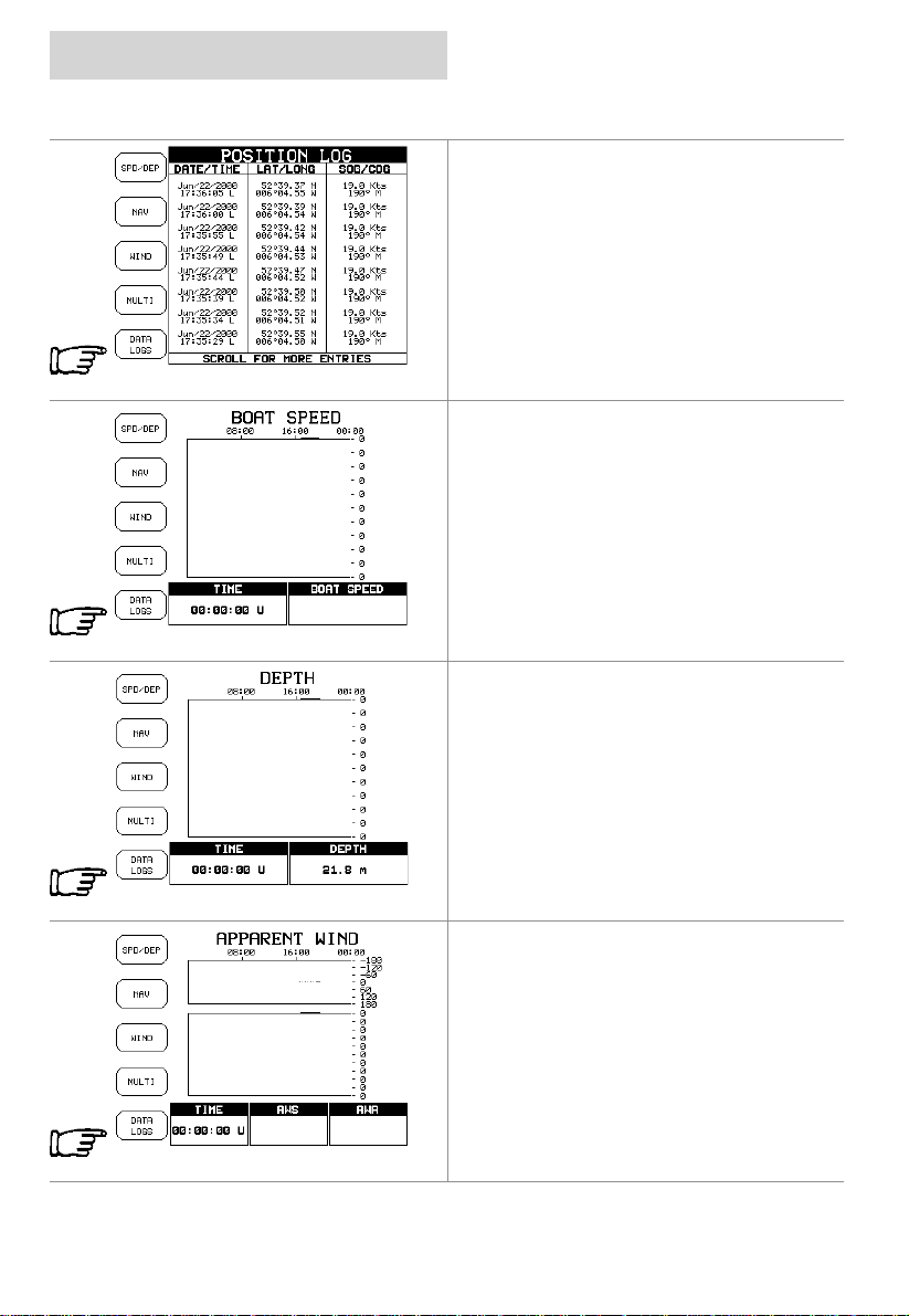
Data Logs
The Data Logging pages are divided into four
pages, accessed by repeatedly pressing the
DATA LOGS Softkey.
Page 24 03/09/01
Page 25
cnd
getting started
GPS Mode
The GPS mode displays positional information
received from an external GPS antenna or unit.
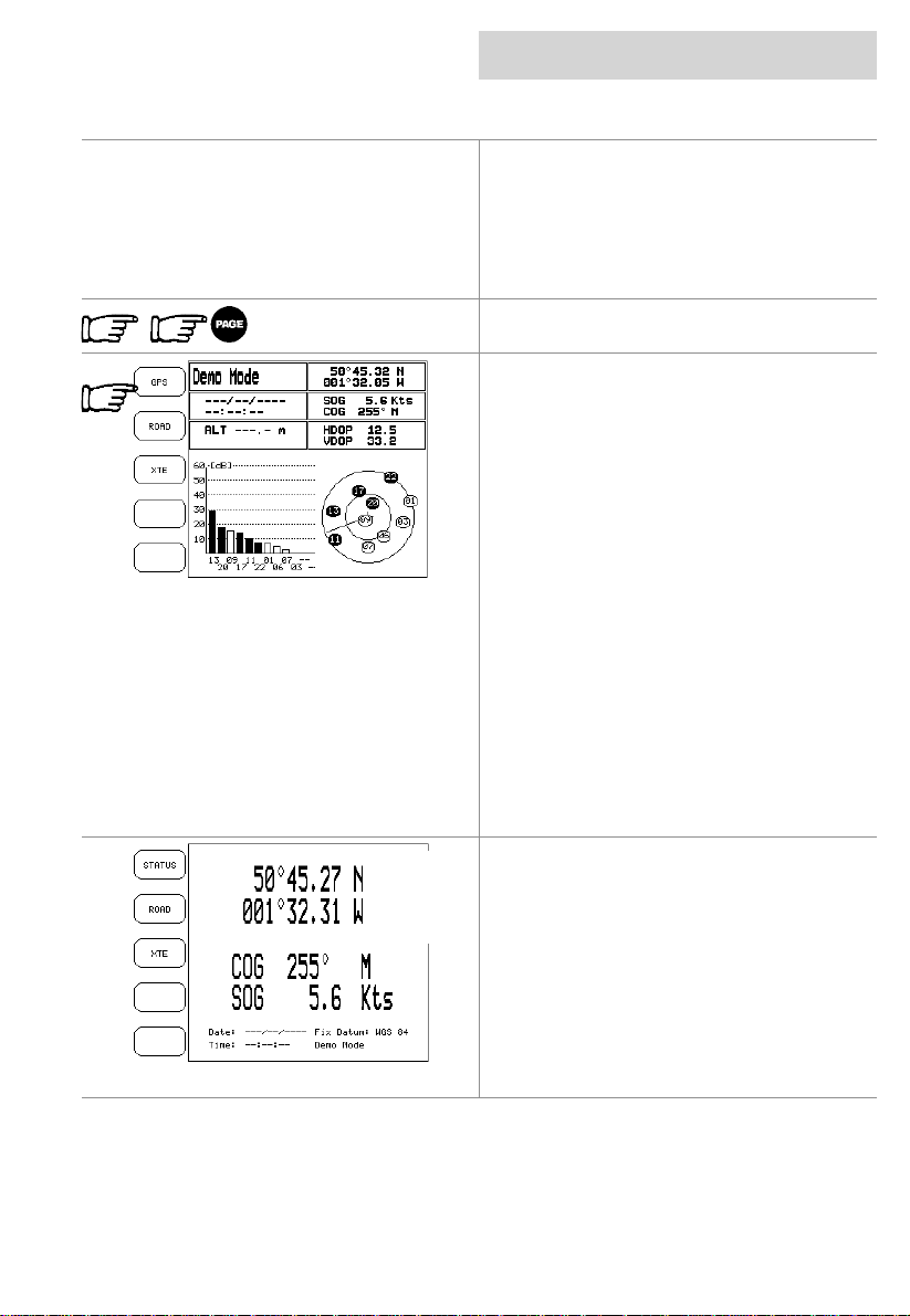
Initialisation
When the CND is first s witched on, it will start
acquiring satellites to obtain a position fix.
Pressing the PAGE key twice will display the
GPS page.
Status Page
The Status page displays inf orm ati on about t he
satellites in use and the quality of t he position
provided.
The bar graph displays the strength of the
signal being received from each sat ellite. The
circular display shows the satellites currently in
view with their identification numbers. These
numbers correspond to the bar graph.
Where a satellite is blacked, it is being used by
the CND for positional inf ormation.
The data boxes are updated when the CND
has obtained a lock on sufficient satellites for
navigation.
The HDOP (Horizontal Dilution of Precision)
and VDOP (Vertical Dilution of Precision)
figures give an indic ation of the ac cu racy of t he
position being calculated. A low figure indicates
increased accuracy.
Pressing the GPS Softkey displays the GPS
Page.
GPS Page
The GPS page displays the current position
with Course Over the Ground (COG) and
Speed Over the Ground (SOG). Also shown
are the Datum on which the positi on is based
and the system date and ti me.
gps mode
03/09/01 Page 25
Page 26
getting started
gps mode
cnd
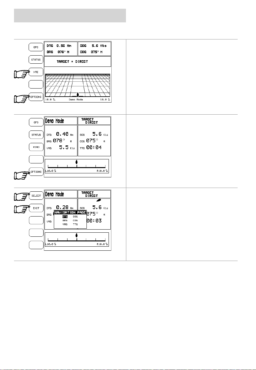
Road Page
Pressing the ROAD Softkey on the Status page
displays the Road Page.
The Road Page shows the current course
displayed on a rolling road with the current
heading up the page. The target waypoint is
also displayed.
Pressing the OPTIONS Softkey displays the
Road Page Options.
Pressing the XTE Softkey displays the XTE
Page
XTE Page
The XTE (Cross Track Error) page displays the
distance from the current position to the closest
position on a line between the last waypoint
and the next waypoint on the leg being
travelled.
Pressing the OPTIONS Softkey displays the
XTE Options.
XTE Options
The Options menu is used for setting the
display fields.
Press the SELECT Softkey to change then
Pressing the EXIT Softkey.
Page 26 03/09/01
Page 27
cnd
advanced features
routes
Main Setup Screen
At anytime, you m ay add or delete waypoints,
see a route sum mary, reverse the direction of
the route or erase the entire route.
The CND can store up to 10 individual routes,
only one can be selected as the c urrent route.
Only the currently selected route can be
navigated to or edited.
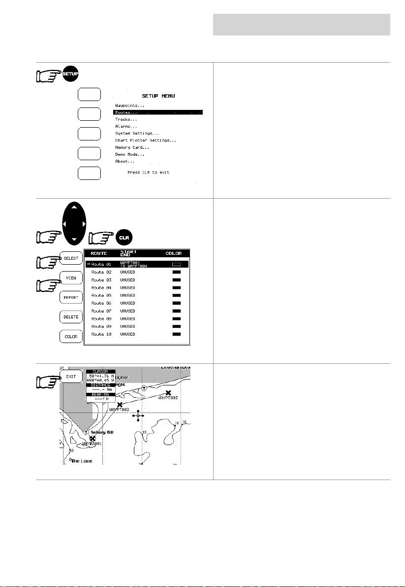
Press the SETUP key
Selecting a route
Using the CURSOR keypad select Routes from
the Setup screen.
From the Main Route screen, the CND displays
a list of available routes.
Routes are permanent ly stored in the memory
as they are created.
Selecting a route to work
Scroll through the routes using the up/down
CURSOR keypad, pressing the SELECT
Softkey selects the route.
When an existing rout e i s selected pressing the
VIEW Softkey will automatically zoom and pan
the chart display to show the route on screen,
The route, shown by straight segments, is
centred on the screen.
The EXIT Softkey returns to the previous
screen.
03/09/01 Page 27
Page 28
advanced features
routes
cnd
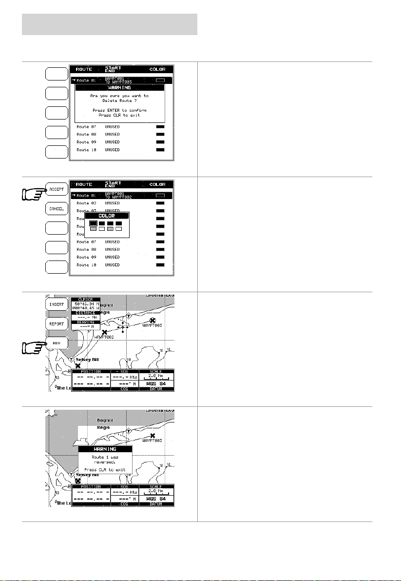
Deleting a route
From the main Route sc reen select the Route
to be deleted and press the DELETE Softkey.
A warning appears confirming the delet e.
Route Colour selection
From the main Route sc reen select the Route
and press the COLOUR Softkey t o display the
eight colour selec t window, use the CURSOR
keypad to select the colour, press the ACCEPT
Softkey to c onfirm. The route appears on the
screen in the s elect ed colour. Y ou can selec t a
different colour for each rout e.
Reversing a route
To navigate to the point where the route
originally started.
Put the cursor over one of the lines on the
route and press the REV Softkey.
This option is onl y avai l abl e when the rout e has
been selected as the acti ve route.
A warning screen will appear to tell you that the
route has been reversed.
Page 28 03/09/01
Page 29
cnd
advanced features
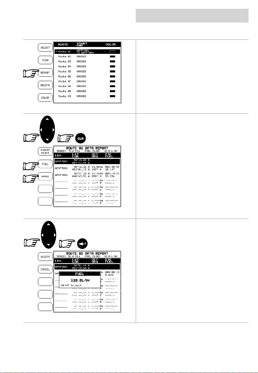
Route Report
Pressing the REPORT Softkey from the main
Route screen will display information about the
Waypoints/ Marks in that route.
If more than six W aypoints are shown, use the
up and down CURSOR keypad to select
another page.
Press the CLR key to exit from Route Data
Report page.
Changing Speed & Fuel values
In the Route Report screen pressing the
SPEED Softkey displays the boats average
speed in Kts, pressing the FUEL Softkey
displays the boat s average fuel c onsum ption in
L/Hr
routes
With the Fuel box displayed, use the CURSOR
keypad to change the value.
Press ENTER key to confirm the change
03/09/01 Page 29
Page 30
advanced features
routes
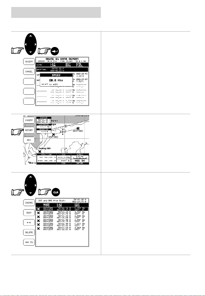
With the Speed box displayed, use the
CURSOR keypad to change the value.
Press the ENTER key to confirm t he change.
Once the estimated Speed and Fuel are
entered, the CND will calculate the estimated
time of arri val at each of the Waypoi nts/Marks
in the route and the fuel required.
Route Report from the chart.
Place the cursor on an existing Waypoint or
route leg and press the REPORT Softkey to
display the same Route Data Report page.
cnd
Finding information on Waypoints
A window is opened, that gives information
about all stored W a ypoi nt s.
Page 30 03/09/01
If there are more than 10 Waypoints shown,
use the up and down CURSOR keypad to
select another page.
Pressing the CLR key will exit from Waypoints
page.
Page 31
cnd
OR
advanced features
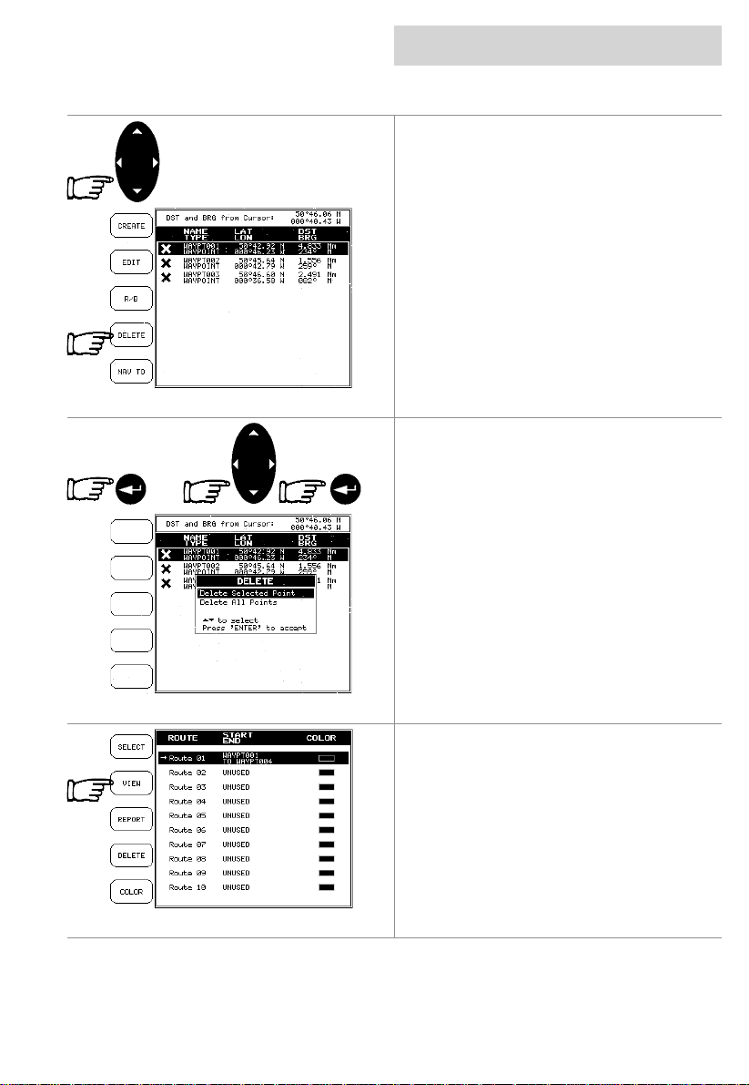
Deleting a Waypoint from the list
Use the CURSOR key to select the Waypoint
to delete then press the DELETE Softkey.
When the delete box appears press the
ENTER key to Delete Selected Poi nt, or using
the CURSOR keypad to select Delete All
Points, then press t he ENTER key.
routes
Viewing Waypoint/Marks in a Route list
Select the route and press the VIEW Softkey
will display the selected route with the
waypoints listed.
03/09/01 Page 31
Page 32
advanced features
routes
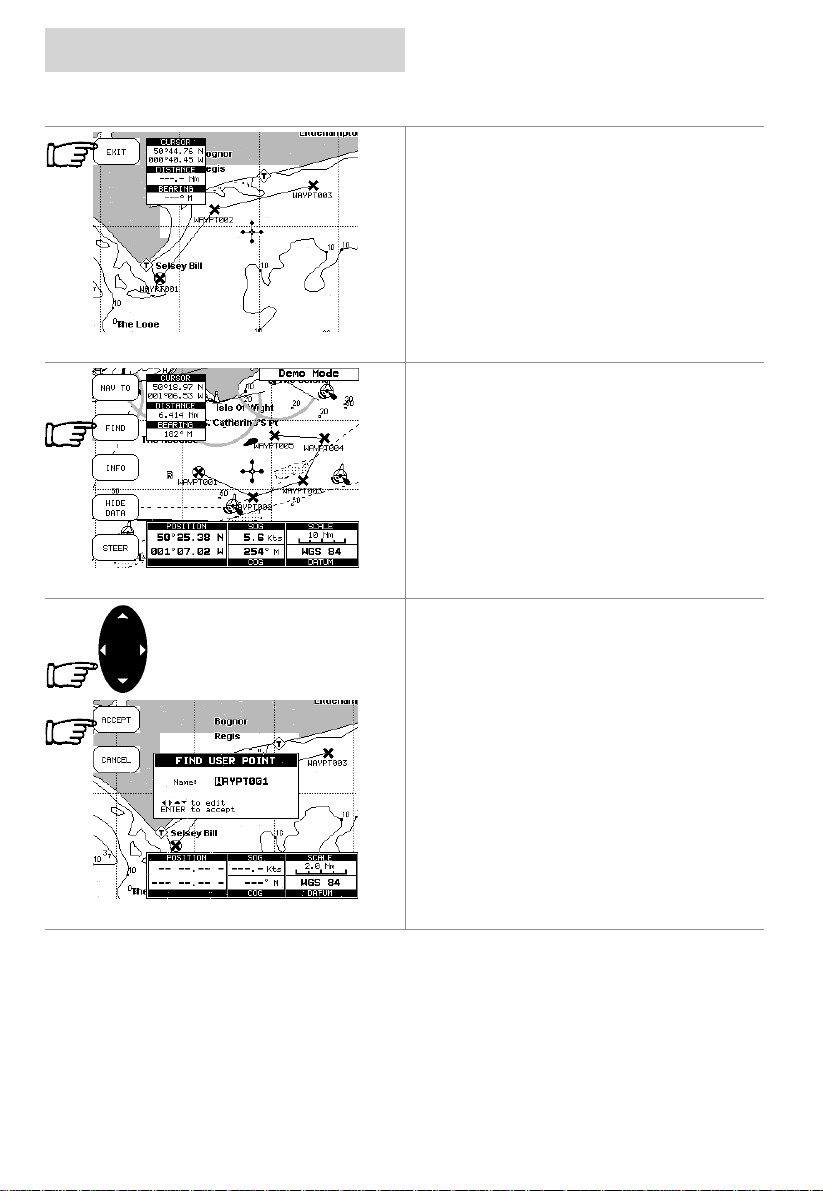
Press the EXIT Softkey to return to the Route
page.
Finding a Waypoint/Mark on the chart
Press the FIND Softkey.
Select Find User Point and pres s ENTER
A window appears to insert the Name by using
the CURSOR keypad. Press the ACCEPT
Softkey to accept, the CND will display the
selected point.
cnd
Page 32 03/09/01
Page 33
cnd
advanced features
marks
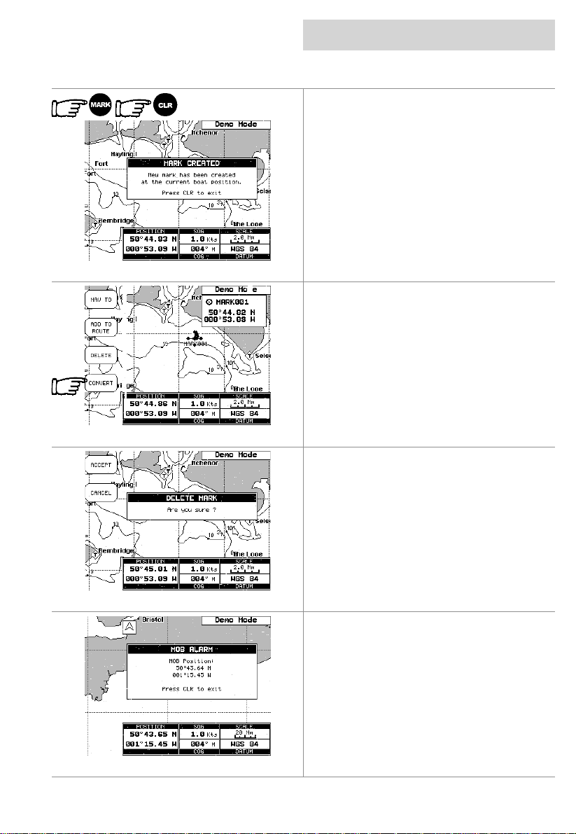
Adding a Mark
Pressing the MARK key inserts a Mark on your
boat’s position. In t he Text Area informati on on
Mark name, symbol and Latitude/Longitude is
shown. Press the CLR key to clear the
message
Converting a MARK to a Waypoint
Place the cursor on the Mark and press the
CONVERT Softkey, a window to confirm the
conversion is displayed
Deleting a Mark
Place the curs or on an existing Mark, press the
DELETE Softkey, a window to confirm the
deletion is displayed
Man Over Board
Press and hold the MARK key for two seconds
to place a MOB symbol at the boat’s current
position. As soon as ‘MOB’ is selected an
Alarm window appears on the screen giving the
position that the MOB occ urred.
Pressing the CLR key removes the Alarm
window.
Press and hold the MARK key for two seconds
03/09/01 Page 33
displays the DISABLE Softkey.
Page 34
settings
setup menu
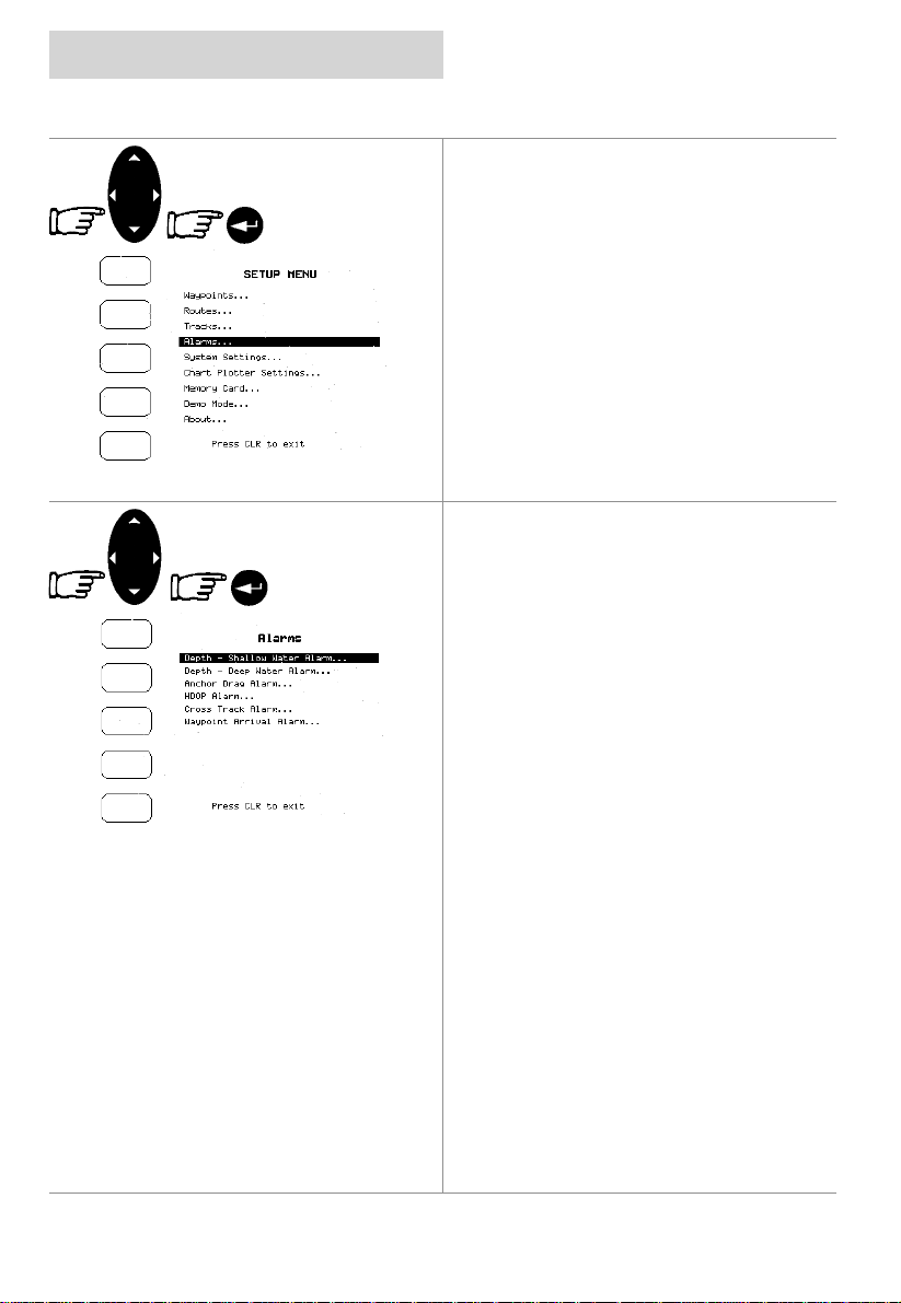
Selecting Alarms
Use the CURSOR keypad to scroll to the
Alarms menu and pressi ng the ENTER key to
select.
Use the CURSOR keypad to enable the alarm,
then use the CURSOR keypad to select and
change the value of a setting, and press the
ENTER key to set.
When an alarm is activated the CND emits a
beep and a pop-up window is opened.
Depth – Shallow Water Alarm
This specifies the minimum depth. Depths
below this value triggers the alarm
Depth – Deep Water Alarm
This specifies the maximum depth. Depths
above this value triggers the alarm.
Anchor drag alarm
Triggers when the boat exits from the anchor
circle. The radius is s et in the Alarm Value.
HDOP Alarm
This specifies the minimum number of satellites
to receive from. Below this number the alarm
sounds.
Cross Track Alarm
This specifies the dist ance perpendicul ar to the
rom line, exceeding this value triggers the
alarm.
Waypoint Arrival Alarm
Specifies the radius of a circle around the
Waypoint/Mark of a route.When your boat
reaches this circl e t he al arm sounds.
cnd
Page 34 03/09/01
Page 35
cnd
settings
setup menu
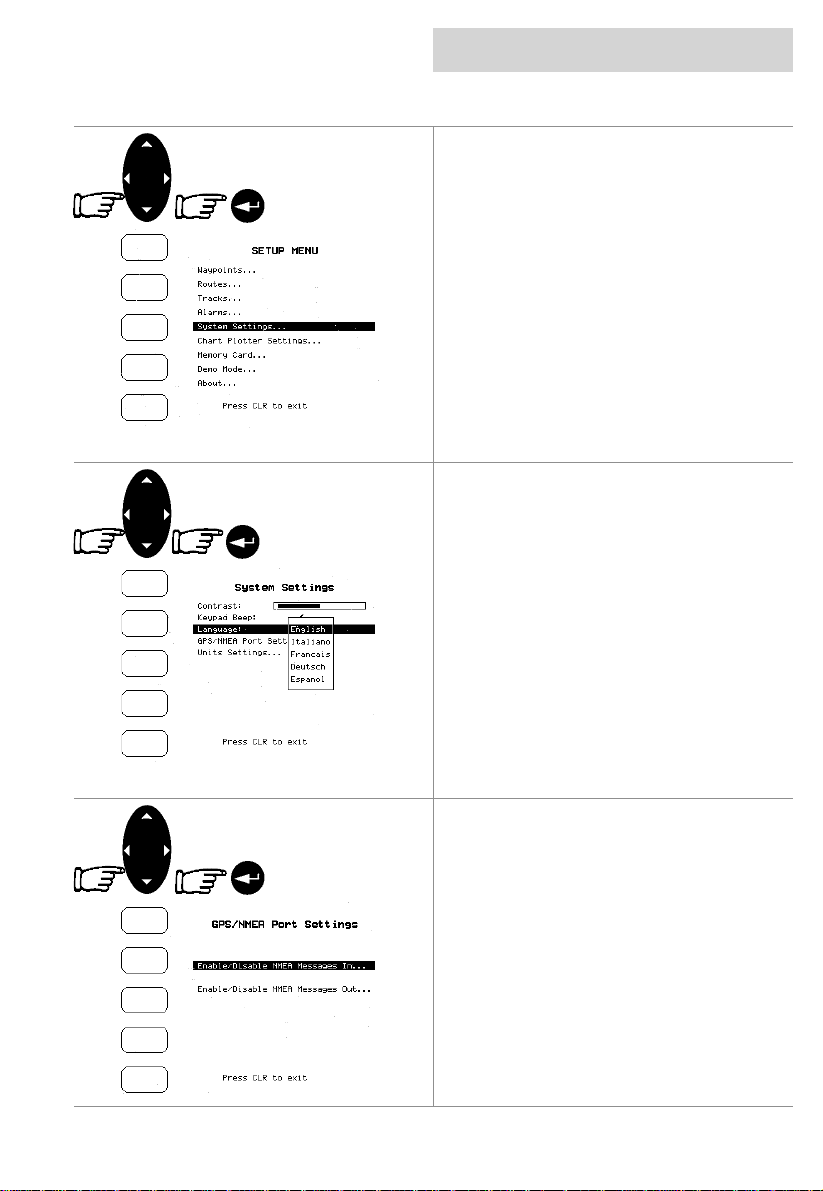
Selecting System Settings
Use the CURSOR keypad to scroll to the
System Settings menuand press the ENTER
key to select.
To set the Language
Use the CURSOR keypad to select language
and press ENTER to reveal the sub menu.
Highlight the desired language and t hen press
the ENTER key.
To set the GPS/NMEA
Use the CURSOR keypad to selec t the NMEA
sub menu and use the ENTER key to confirm
the settings.
03/09/01 Page 35
Page 36
settings
setup menu
cnd
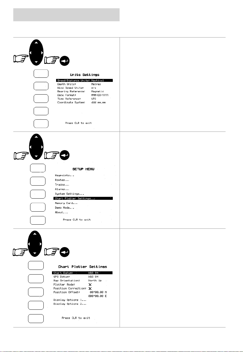
To set the Units
Use the CURSOR keypad to select the units
settings menu and press the ENTER key to
confirm changes.
Selecting Chart Plotter settings
Use the CURSOR keypad to scroll to the Chart
Plotter Settings menuand press the ENTER
key to select.
Use the CURSOR keypad to select the sub
menus or to change the value of a setting.
Press the ENTER key to select.
Page 36 03/09/01
Page 37
cnd
setup menu
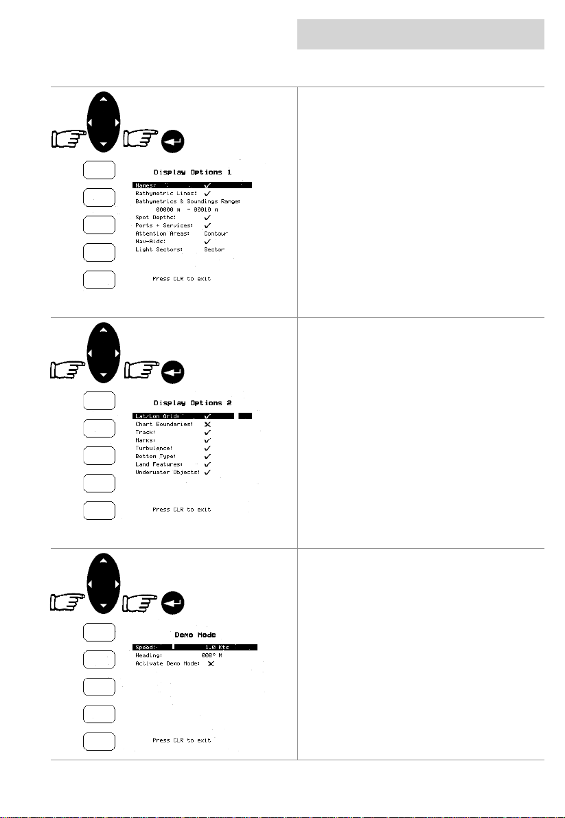
To set the Display Options 1
Use the CURSOR keypad to select a sub menu
or to change the value of a setting, and press
the ENTER key to select.
It should be noted that these Display Option
settings are stored when the CND is turned off.
To set the Display Options 2
Use the CURSOR keypad to select a sub menu
or to change the value of a setting, and press
the ENTER key to select.
It should be noted that these Display Option
settings are stored when the CND is turned off.
settings
Selecting Demo Mode settings
Use the CURSOR keypad to scroll to Demo
Mode and press the ENTER key to select.
Use the CURSOR keypad change the values of
the Speed and Heading, and press the ENTER
key to select.
Active Demo Mode sets the CND to run in
Demo Mode. This is an ideal way to become
familiar with the system.
The default is off.
03/09/01 Page 37
Page 38
settings
setup menu
position correction
cnd
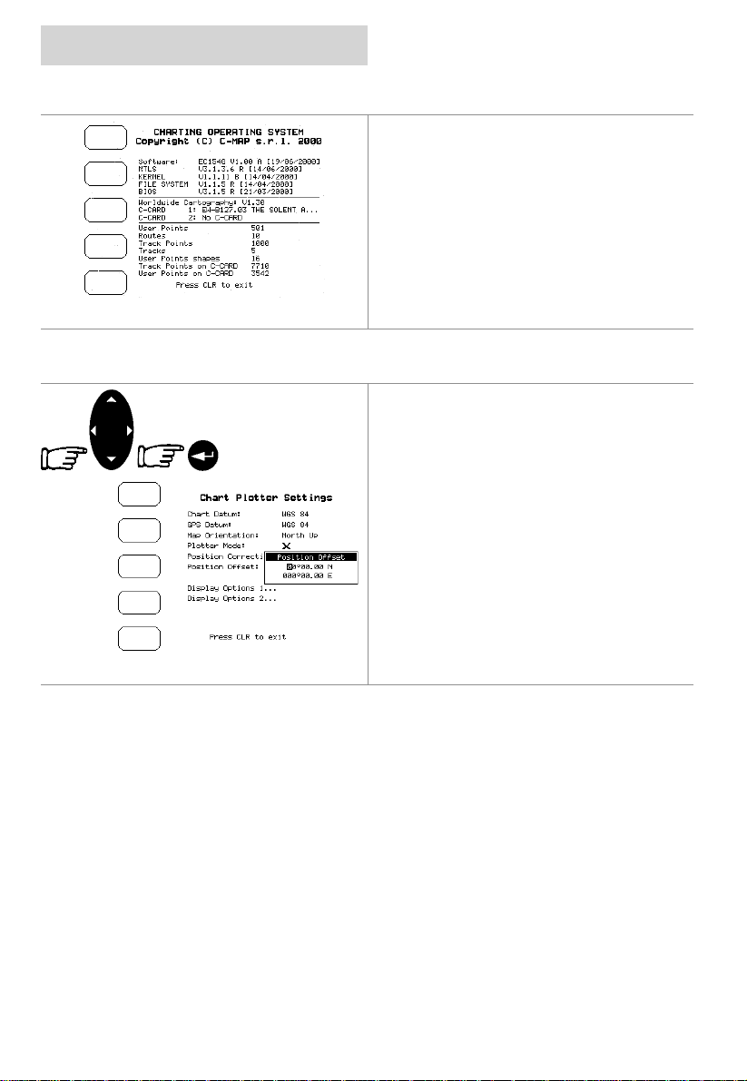
Selecting About
This page displays the sof tware and C_CARD
information.
Position Correction
Position Correction applies an offset to your
GPS position fix which will then place your boat
exactly on the chart where it should be. From
the Plotter Setup menu, select Position Offset
and press the ENTER key. Manually adjust the
offset by the amount requi red t o pl ace your
boat accurately on the chart.
Note
The position correction feat ure should be used
with care. Datum shifts and poor survey data
are not always consistent and can be very
localised. In areas where these errors occur the
traditional methods of navigation should be
used.
Page 38 03/09/01
Page 39
cnd
track functions
Track functions
A very useful feature of the CND is the ability to
store and display exactly where the boat has
been. This feature, ref erred to as Track ing, c an
provide invaluable information about the effect
of tide and wind influence on the boat’s
progress as well as giving an indication of the
helmsman’s perf ormance.
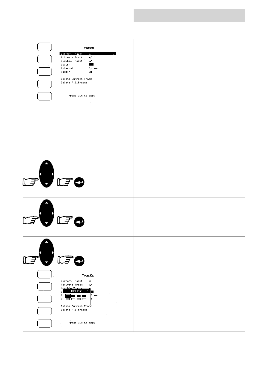
Enabling Track Storing
To switch on/off the track storing, select Tracks
from the Setup menu, use the CURSOR
keypad to scroll down to Activate Track and
press the ENTER key to toggle between on
and off.
Note
It is not possible t o use the track storing if you
are not receiving a valid fix.
Selecting Active Track
Use the CURSOR keypad to sc roll to Current
Track, and pressing the ENTER key repeatedly
to select the desired number of the active track.
The default setting is 1.
Displaying Track
Use the CURSOR keypad to scroll to Visible
Track, press the ENTER key to make the track
visible (On) or hidden (Off ). The default sett ing
is On.
Selecting Track Colour
Using the CURSOR keypad to sc roll to Colour,
press the ENTER key and use the CURSOR
keypad to select the desired colour from the
eight colours available for the selected track.
Press the ENTER key to select the colour. The
default colour is black .
settings
03/09/01 Page 39
Page 40
settings
track functions
cnd
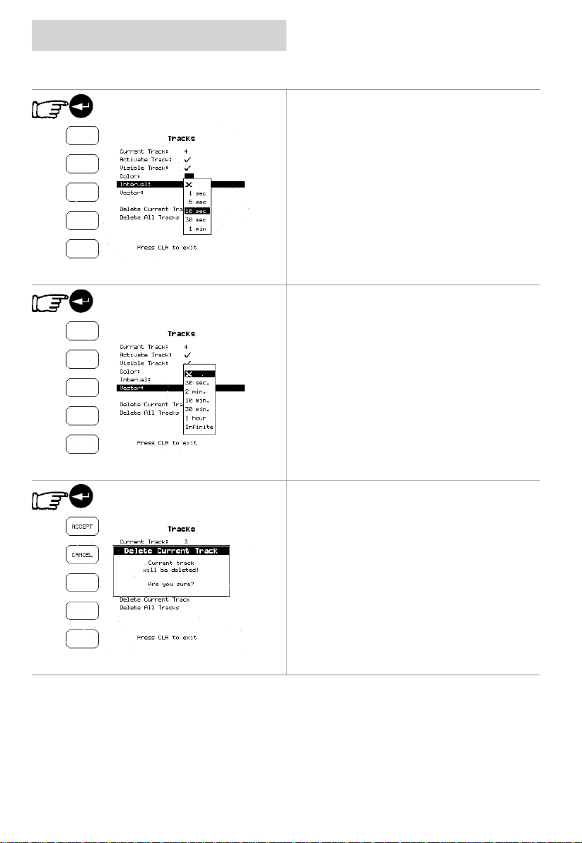
Selecting Time Interval
It is possibl e to change the frequency that the
CND records the boat’s posit ion in memory. It
is important to match the frequency of
recording to the distanc e that your boat will be
travelling in order that the whole passage can
be tracked. To change the frequency, select
the “Interval” option using the up/down
CURSOR key and change the time between
recording by pressing the ENTER key. The
maximum interval available is 1 minute which
gives a total maxim um Tracking period of over
11 hours. The default setting i s 10 sec.
Selecting Vector
Vector feature displays a vector line protruding
from the boat showing where the boat will be in
a set period of time. This line is bas ed on the
boat’s current speed and course and i s useful
for indicating at any given time where the boat
is heading. Various lengths of vector are
available, also Off to disable the Vector line
display. Use the up/down CURSOR key and
change the time bet ween recording, press the
ENTER key to confirm.
The default setting is Off.
Delete Current Track
Deletes all the track memory. A warning
message appears, press the ENTER key to
confirm deletion.
Page 40 03/09/01
Page 41
cnd
memory menu
Memory Menu
The CND allows you to copy inf orm ati on to and
from User C-CA RD’s, returning the inf ormation
to internal memory at a later time. This allows
virtually unlimited storage.
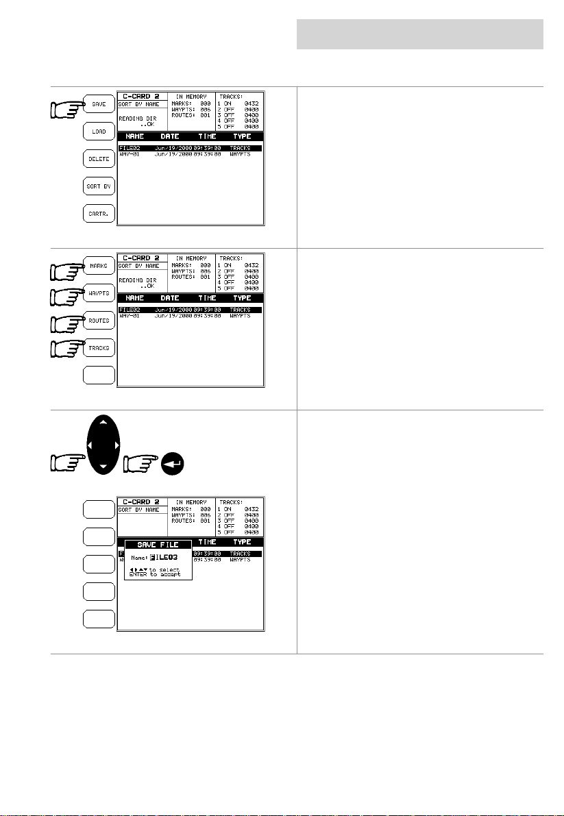
Saving a File
A window is opened to insert the file name and
the type of data to save.
Choose the type of data to save by pressing
the related Softkey,
Use the CURSOR keypad to choose the file
name. At firs t a def ault nam e is s hown, use t he
CURSOR keypad to insert the name, then
press the ENTER key.
Note
The maximum length of the filename is 8
characters. The characters may be numbers
(0, ..., 9), letters (A, ..., Z) and spac es.
settings
03/09/01 Page 41
Page 42
settings
user c-card menu
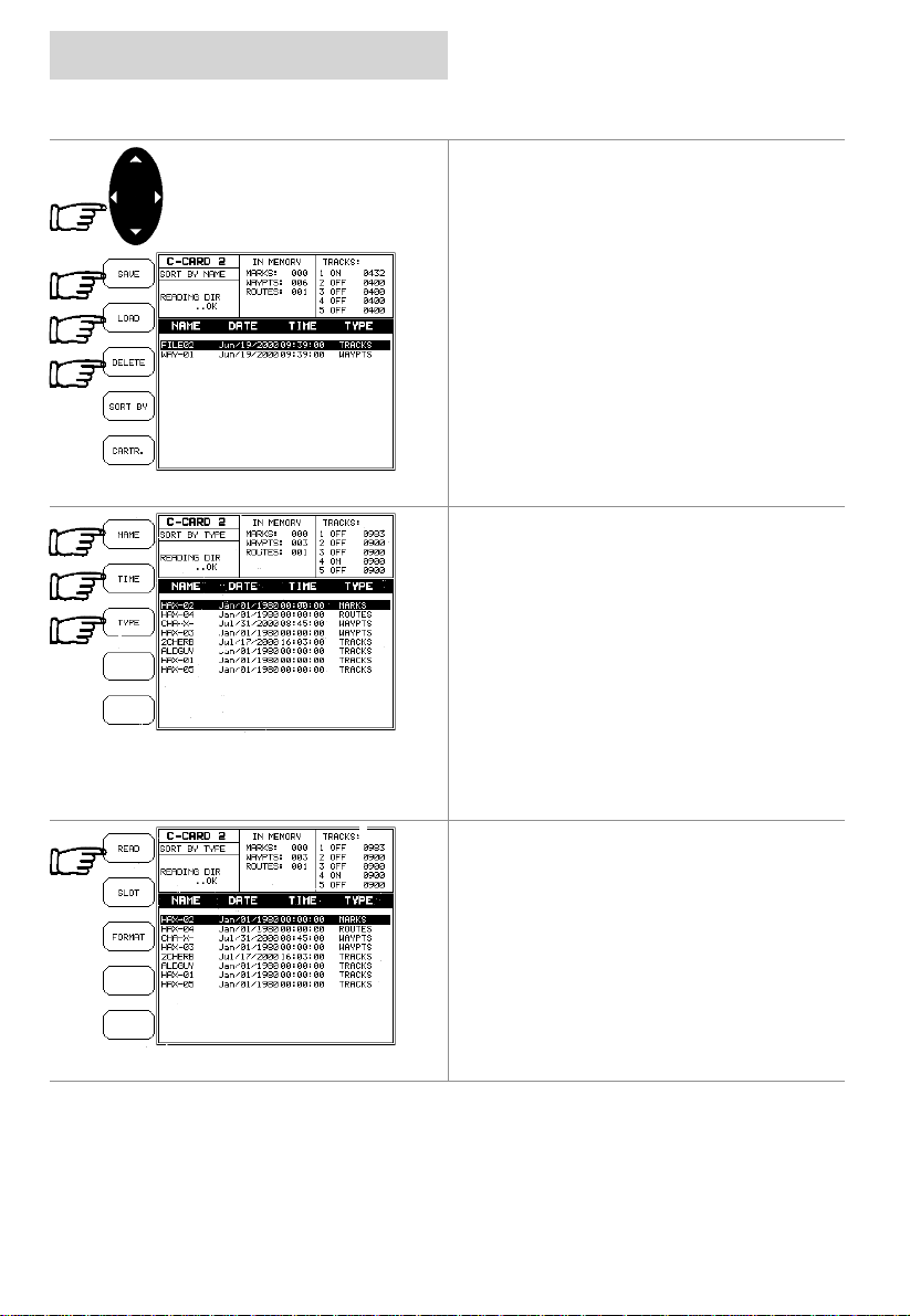
Loading a File
Choose the file name in the list using the
CURSOR keypad, then press the LOAD
Softkey to return the information to internal
memory.
Deleting a File
Use the CURSOR keypad to select the item,
press the DELETE Softkey to delete the file
from the C-CARD.
This option permanently erases the selected
file.
Sort the User C-CARD Directory
The contents of t he C-CARD i s di splayed when
you enter this mode.
It is possible to sort the file directory. This is
possible in three different modes, select the
SORT BY Softkey then select one of the
options.
NAME Softkey to order by the
TIME Softkey to order by the tim e of
TYPE Softkey to order by the type of
Press the
filename;
Press the
file creation;
Press the
data.
Reading the User C-CARD
Pressing the READ Softkey lists the files
present on the User C-CARD insert ed.
Selecting slot
Select the des ired slot where to insert the Us er
C-CARD.
cnd
Page 42 03/09/01
Page 43
cnd
settings
user c-card menu
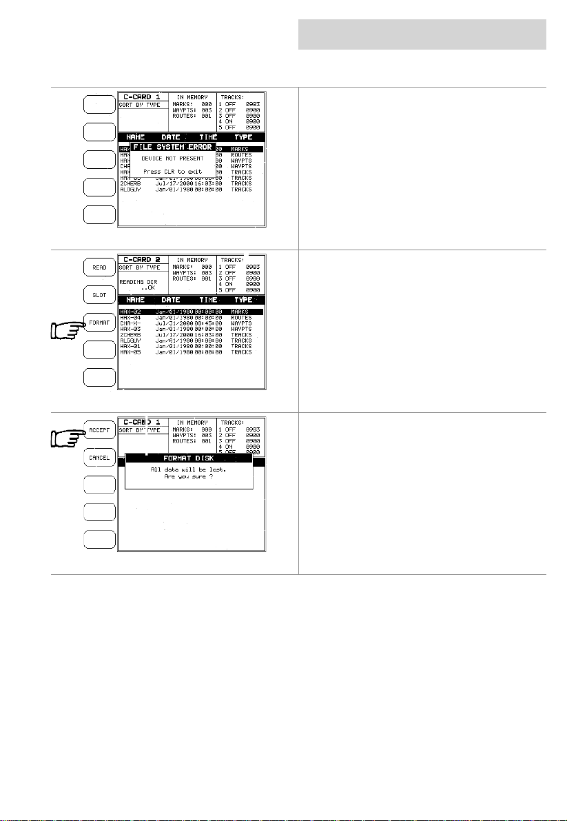
If the User C-CARD is not present in the
selected slot, a warning m essage appears.
Formatting User C-CARD
A User C-CARD mu st be form at ted bef ore use.
This operation prepares the User C-CARD to
receive and store informat i on.
Pressing the FORMAT Softkey will display a
box to advise that all data will be lost.
Pressing the ACCEPT Softkey will format the
C-CARD.
If a used User C-CARD is formatted, all
previously stored data on the User C-CARD will
be completely deleted.
03/09/01 Page 43
Page 44

appendix a
technical specifications
• Dimensions mm (inch): 220 x 155 x 70.6 (8.66 x 6.10 x 2.78)
• Power consumption: 12 Watt m ax, 10 - 35 Vol t dc
• GPS Interface: NMEA 0183 ver 2.3
• Autopilot Interface: NMEA 0183 ver 2.3
• Instrument Interface: NMEA 0183 ver 2.3
• Display mm (inch): LCD colour TFT transflective
active area 142mm (5.6")
• Display Resolution: 320 x 240 pixels
• Cartography: C-MAPNT
• Temperature range: -10/+60 degrees Celsius
cnd
• Memory: Non volatile with battery back-up
• Keyboard: Silicon rubber, backlit
• Weight: 950g
• Sealing: IP67 (With door closed)
• Accessories: Bracket
Flush mounting kit + mounti ng template
Power supply and I /O cable
Protective cover
User manual
Page 44 03/09/01
Page 45
cnd
E
A
appendix b
installation
Precautions
To avoid electromagnetic interference, it is
recommended that the CND be installed no
less than 0.3 metres from a compass and 1
metre from the GPS .
The CND is water resist ant, but not waterproof.
Use the cover when not in use. The C-MAP
Cover must be properly closed and only
opened to insert or remove c artridges. In either
situation, this process must be perf ormed in a
totally dry environment. The rear connectors
that are not connected to c ables must remain
protected by their appropriate caps .
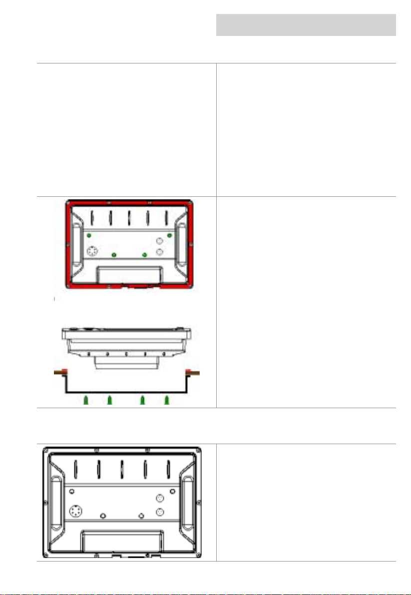
Panel mounting
Screw the bolts supplied into t he fittings on the
back of the CND. A hole m ust be cut in the
panel using the template supplied. Fit the CND
into the hole you have cut and place the
mounting bracket so that the panel is
sandwiched between it and the CND. Fit the
knobs onto the bolts and ti ght en.
The rubber sealing gasket should be placed
between the plotter and bulkhead to prevent
moisture penetration and reduc e the effects of
any vibration transmitted through the
instrument panel.
electrical connections
Electrical Connection
Connections on the back of the CND
NME
Power/Data
03/09/01 Page 45
NM
FastNet 2
NMEA – Data from non B&G instruments.
Power/Data – Data from GPS antenna.
2
Fastnet
– Connects CND to h1000 system.
Page 46
appendix b
electrical connections
cnd
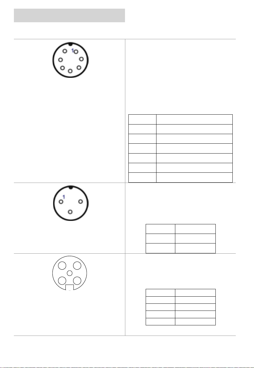
Power/Data
This is the main P ower and Navigation NMEA
port. The CND receives data from the GPS
receiver and sends data to the instrument
system using this port. Sentences decoded:
DBT, DPT, GGA, GLL, GSA, GSV, HDG, HDM,
HDT, MWV, RMC, VHW, VTG, VWR, VWT,
WPL, ZDA and DTM (B&G special). Sentences
Transmitted: APA, APB, BOD, BWC, BWR,
DBT, GGA, GLL, HDG, HSC, RMA, RMB,
RMC, VTG, WCV, XTE, ZDA and VTG.
Pin Colour Signal
Red 1 +12 VDC
Black 0 VDC/NEMA OUTPUT (GND)
Blue NEMA OUTPUT +
Green NMEA INPUT +
White UNUSED
Yellow NMEA INPUT –
Screen SCREEN
NMEA In (Instrument Interface)
Auxiliary NMEA input port for NMEA messages
transmitted by the instrument system.
Sentences decoded: DBT, DPT, HDG, HDM,
HDT, MWV, VHW, VWR, VWT and WPL.
Pin Colour Signal
RED 1 NMEA INPUT+
Blue NMEA INPUTGreen SCREEN
Fastnet2
2 3
5
41
Front view of
male connector pins
One FastNet² connector is provi ded at t he rear
of the unit. For connection to the h1000
system.
Pin Number Signal
12V
1
2
3
4
5
Busy
FastNet²FastNet²+
0V
Page 46 03/09/01
Page 47
cnd
appendix c
terms and functions
This section explains the terms t hat may be unfamiliar to the reader.
Some terms are f ollowed by a brief description on how to select the related menu option, listing
the key sequence.
About (page)
Activate Demo Mode
Anchor Ala rm
Arrival Alarm
Arrival Time
Attention Areas
Azimuth
Bathymetric Lines
Selects a page that gives information on
software and cartography version and general
software specificati on.
The Demo Mode can be very useful to
familiarise yourself with the operation of the
CND as you do not need to have a GPS
connected
The default setting is Off.
Specifies the radi us of an anchor circl e around
the boat, when exiting from the circ le, the CND
emits an alarm and a pop-up window is
opened.
The default setting is Off.
Specifies the radius of a circle around the
Waypoint/Mark of a route: when your boat
reaches this circl e the alarm sounds.
The default setting is Off.
The estimated time of day you will reach your
destination, based on your current speed and
track from GPS.
Enables by filling area (On), enables only
contour (Contour) or disables (Off) the display
of Attention Areas. A special symbol (!) is
placed inside the area select ing On or Contour
options. This is valid also for the categories:
FISHING FACILITY, MARINE
FARM/CULTURE, MILITARY PRACTICE
AREA, RESTRICTED A REA, and SEAPLANE
LANDING AREA. W hen the area is small, it is
identified only by the boundary.
The default setting is Cont our.
The angular measurem ent from the horizon to
a satellite or another object.
Imaginary lines connecting points of equal
water depth.
The default setting is On.
03/09/01 Page 47
Page 48
appendix c
terms and functions
cnd
Bathymetrics & Soundings Range
Beacon
Bearing
BRG = Bearing
Bottom Type
Buoy
Chart Boundaries
Sets the min/max value for Bathymetrics and
Soundings. If the depth unit is Metres (Mt), the
range is [0 - 15000], i f Feet (Ft ) is [ 0 - 49212],
if Fathom (FM) is [0 - 8202].
The default setting is [0, 33] Ft.
A prominent, specially constructed object
forming a conspicuous vertical mark as a fixed
aid to navigation.
Selects either degrees magnetic, (Magnetic), or
degrees true, (True). If magnetic readings are
selected the variation is computed
automatically for every zone as soon as the
chart is displayed.
The default setting is Magnetic.
It is the angle between the North (True or
Magnetic) and a destination. It represents the
direction to follow.
Turns On/Off the displaying of Bottom Type
(type, colour and other qualities of seabed).
The default setting is On.
A floating object m oored to the sea bot tom in a
particular (charted) place, as an aid to
navigation.
Enables/Disables the displaying of the Chart
Boundaries. Selecting A uto ins tead, if we are in
background charts only the first charts level
contained in the C-CARD are displayed, if we
are in a charts level cont ained in the C-CARD
the next four charts level are displayed. The
default setting is On.
Chart Datum
Page 48 03/09/01
Sets the datum that the electronic chart is set
to. This value should be t he sam e as the paper
chart that is being used. In some instances, it
may be beneficial to s et this value to WGS 84
so that two charts of different original datum
can be shown together on the CND .
WGS 1984 is t he def aul t Chart Datum.
Page 49
cnd
appendix c
terms and functions
COG = Course Over Ground
Coordinate System
XTE = Cross Track error
CTS = Course To Steer
Current
Date Format
Datum
Dedicated key
Default
Depth Contours
Depth Units
DGPS = Differential GPS
Distance
Direction of the path over ground actually
followed by a boat.
Sets your preferred Coordinate System among
ddd mm ss, ddd mm.mm, ddd mm.mmm,
The distance from the boat’s present position to
the closest point on a line between the origin
and destinations Waypoints of the navigation
leg being travelled.
The optimum direction the boat should be
steered in order to efficiently make headway
back to the course line while also proceeding
toward the destination Waypoint.
Non-periodical movement of seawater,
generally horizontal, due to many caus es such
as different temperatures and prevalent winds.
Sets your preferred date between MMMM-DDYYYY (month-day-year) and DD-MMMM-Y YYY
(day-month-year).
The Latitude and Longitude lines printed on
any map are based on certain models of the
shape of the earth.
A key with permanently defined function. These
keys are labelled on the front panel of the CND.
Indicates a value or a sett ing that is used if the
user has not defined a particular val ue.
Imaginary lines connecting points of equal
water depth (see also Bathymet ri c Lines).
Sets the depth units among Ft = Feet, FM =
Fathoms and m = Metres . The default setting is
m.
Provides even greater positioning accuracy
than standard GPS
Sets the distance at which the previous three
alarms (Arrival Alarm , Anchor Alarm, and XTE
Alarm) are triggered. The default set ting i s 0.01
Nm.
03/09/01 Page 49
Page 50
appendix c
terms and functions
Distance Units
DTG = Distance To Go
File
Find User Point
Formatting
Full Map Display
GPS = Global Positioning System
GPS Datum
GPS Position (page in GPS Mode)
GPS Signal Status (page in GPS Mode)
Heading (Demo Mode)
HDG = Heading
cnd
Sets the distance unit among Nm = nautical
miles, Mi = miles and Km = kilometres. The
default setting is Nm.
The actual distance to reach the Target.
File is a collection of information stored on a
User C-CARD. Each file must have a unique
name.
Finds the desired User Point on the chart , after
inserting the name.
The formatting of a User C-CARD must be
done before using a new User C-CARD.
The CND will rem ove the information box and
display a full screen c hart and the softkeys.
GPS is a satellite based navigation system
operated by the US Departm ent of Defence. It
gives the navigator a position 24 hours a day,
365 days a year under any weather conditions.
Sets the datum that the GPS unit is set to. If
the internal GPS is being used this value
should be set to WGS 1984. If an external GPS
is used, find out what datum the external GPS
is set to and set the sam e datum value for this
option. The default value is WGS 1984.
The GPS Position Page shows the position and
COG/SOG.
The GPS Signal Status page provides the
satellite fix status.
The value of simulated cours e required during
the Demo Mode. It is recommended that this
value corresponds to the approx. bearing
between the two Marks that the Demo Mode
will “sail” between.
The default setting is 000° M.
The horizontal direction i n which a boat actually
points or heads in any moment.
Page 50 03/09/01
Page 51
cnd
HDOP = Horizontal Dilution Of Preci sion
Keypad Beep
Info
Land Features
Language
Latitude
LAT/LONG
Lat/Long Grid
Light Sectors
appendix c
terms and functions
It is the index for position-f ixing accuracy. The
smaller the HDOP value, the more accurately
the position can be fixed.
Enables/Disables the keypad beep.
The default setting is On.
Displays a screen with a lis t of all objects found
in the range of the cursor.
Turns On/Off the displaying of Landmarks (any
prominent object such as monument, bui lding,
etc, on land that can be used in determining a
location or a direction).
The default setting is On.
Selects the language in which you wish sc reen
labels, menus and options information to be
displayed.
This does not affect t he map information.
The default setting is E ngl ish.
The angular distance North or South of the
equator measured by lines enci rcling the earth
parallel to the equator in degrees from 0° to
90°.
Coordinate system using Latitude and
Longitude coordinates to define a position on
earth.
Turns On/Off the displaying of the Latitude and
Longitude Grids.
The default setting is On.
Turns On or Off of al l the Fixed Lights, Buoys
and lighthouses. When Lights are on, lights are
shown on lighthouses and other lights that
rotate, a light sector is displayed to show the
range of coverage for the light. I n the No sector
setting, the light is shown without sector.
The default setting is S ec tor.
03/09/01 Page 51
Page 52
appendix c
terms and functions
LOG
Longitude
Magnetic Deviation
Magnetic Variation
Map Orientation
Mark
Marks
Memory CARD
Minimum Depth
MOB = Man OverBoard
Inserting MOB
cnd
Speed of the boat relative to the water.
The angular distance East or West of the prime
meridian (Greenwich meridian) as m easured by
lines perpendicular to the parallels and
converging at the poles from 0° to 180°.
The angle between the Magnetic North and the
Compass North.
The angle between the magnetic and
geographic meridians at any place, expressed
in degrees West or East to indicate the
direction of magnetic North from true North.
Selects the orient ation of your chart, North Up:
the map is shown with North upwards. Track
Up: the map is shown with the boat’s current
heading upwards.
The default setting is Nort h Up.
If Track Up is selec ted, a window is opened to
insert the Resolution angle.
Reference points related to c ursor position.
Turns on or off the user entered Marks.
The default setting is On.
The CND uses the optional User C-CARD to
save user data.
Sets the minimum depth that the navigator
wants the boat to go into. This value s ets the
depth area shading i.e. all depth areas less
than this value are shaded (not an alarm)
The default setting is 10m.
It is an important function useful in the case
someone or somethi ng f a l l s overboard.
As soon as ‘MOB’ is pressed, then an Alarm
window appears in the screen giving the
position that the MOB occ urred.
Page 52 03/09/01
Page 53
cnd
Deleting MOB
Names
Nav-Aids
NMEA-0183
Output Format
Plotter Mode
Plotter Setup (menu)
Port By Name
appendix c
terms and functions
To cancel the MOB m ode, press and hold the
‘MARK’ key for two seconds.
Turns On/Off the displaying of the local area
names.
The default setting is On.
Turns On/Off the Buoys and Beacons.
The default setting is On.
The NMEA-0183 Data Interface Standard was
developed by the National Marine Electronics
Association of America. It is an international
standard that enables equipment from many
different manufactures to be connected
together and to share informat i on.
Disables (Off) or sets the interface among
0183, 0180, 0180/CDX. The default setting is
0183.
Selects whether areas not covered by the
electronic charts on the C-CARD can be
viewed. If set to On, then the user c an zoom i n
to view Marks, routes, tracks and boat’s
position anywhere in the world down to a zoom
level of 0.008 Nm (Screen width = 15 metres),
regardless of what charts are on t he C-CARD.
If set to Of f then the CND will only display the
areas covered by the chart. W hen the edge of
chart coverage is reached, the CND will
automatically zoom out to the next available
smaller scale chart.
The default setting is Off.
Enables/Disables the Plotter Mode and the
Position Correction, selects the desired value
for Position Offset, GPS Datum, Chart Datum.
Press the CLR key to return to the previous
menu.
To locate and display the port inserting the
name.
The icon list of the available servic es is shown
on the screen.
03/09/01 Page 53
Page 54
appendix c
terms and functions
Port Info
Ports and Services
Port Services
Position Correction
R/B
Resolution
Rolling Road (page in GPS Mode)
cnd
The Port Info function is a combination of a
new Port Info database containing all the
relevant Safety and Navigational information
normally found in good pilot book s and a new
presentation software which displays special
Port Facility Symbols.
Turns On/Off the displaying of Ports and
Services.
The default setting is On.
To locate and display the nearest available
facilities of a particular type (i.e. the nearest
Hospital, sailmaker, bank, etc.).
The icon list of the available servic es is shown
on the screen.
Allows the user to correct for any position
inaccuracy due to datum s hifts or poor survey
data. This can sometimes occur in areas where
the original paper charts are produced from
very old survey data or where the chart has an
unknown datum or datum that is not listed on
the CND list of datums.
Allows the range and bearing between two
positions on the chart t o be calculated
It is the resolution angle for the Map
Orientation, range [5, 30] degrees. The default
setting is 15°.
From this page it is pos sible t o display the next
targets bearing (BRG) and distance (DTG), go
on to the previous or next Target, or display the
Route Data Report.
Page 54 03/09/01
Page 55
cnd
Route
Setup (menu)
Simulation
SNR = Signal to Noise Ratio
SOG = Speed Over Ground
Soft key
Speed
Speed Units
Split Map Display
Spot Depths
STR = Steering
Tide
appendix c
terms and functions
Sequence of Waypoints connected by legs.
Only the currently select ed/displayed route c an
be navigated to or edited.
The Setup menu is where all the settings and
adjustments are made.
Used in order to use your CND without input
data.(see Demo mode)
The ratio of the magnitude of a signal that of
the noise (interference).
A calculation of the rate of movement of the
boat over the ground.
There are 5 Softkeys, which have different
functions when you select different modes of
operation; the labels for the current functions
are shown on the screen im mediately adjacent
to the keys.
The current velocity at which you are travell ing,
relative to a ground location.
Sets the speed uni t among Kts = knots, Mph =
miles per hour, Kph = kil ometres per hour. The
default setting is K ts.
In Split Map Display the sc reen is spl it between
showing the chart on t he top of the sc reen and
a useful inform ation text box on bottom of the
screen.
Turns On/Off the displaying of Spot Depths (the
depth of the water in a specific and charted
position). The default set t i ng i s On.
The difference between COG and CTS. If COG
is 25° and CTS is 30°, then S T R i s 5° Right.
The periodic rise and fall of the surface of
oceans, bays, etc., due principally to the
gravitational interactions between the Moon
and Earth.
03/09/01 Page 55
Page 56
appendix c
terms and functions
Tide Inf o
Tide Stations
Time/Date Setup (menu)
Time Reference
Track
TRN = Turning
TTG = Time To Go
Turbulence
Underwater Objects
Units Setup (menu)
cnd
The Tide Info feature is the combination of a
tide heights database that is included within
new C-CARDs and features which calculat e the
tide graph for all primary and secondary ports
world-wide, plus the times of Sunrise and
Sunset. At some chart levels, the CND will
display a Tide Diam ond Symbol for every Port
or tide point in the database covered by that
particular C-CARD.
Finds the nearest Tide Stat ions (up to 10) on
the map, from the boat posit ion - if a valid f ix is
received - or from the cursor posit ion - if the fix
position is not good.
Selects the desired value f or Time Reference,
Time Format, and Date Format . Press ‘CLEAR’
to return to the previous menu.
Sets UTC or Local Time.
The default setting is UTC.
A very useful feature of t he CND, is the ability
to store and display exactly where the boat has
been. This feature is referred to as Tracking.
The difference between COG and BRG. If COG
is 80° and BRG is 75°, TRN is 5° Left.
The estimated time needed to reach your
destination, based on your current speed and
the distance to desti nat i on.
Turns On/Off the displaying of water turbulence
symbols. The default s etting is On.
Turns On/Off the displaying of Underwater
Objects. (Diffuser, Obstruction, Wreck, Cable submarine, Cable area, Pipeline area, Pipeline
- submarine/on land. The default setting is On.
When the Units S etup option is selected from
the Setup menu, a sub-m enu is displayed that
allows the various units that the CND uses to
be selected and adjusted.
Page 56 03/09/01
Page 57
cnd
User C-CARD
User Point
User Points List
Waypoint
WGS-84 = World Geodetic System 1984
Zoom-In
Zoom-Out
UTC = Universal Time Coordinated
XTE Alarm
XTE Display (page in GPS Mode)
appendix c
terms and functions
The CND uses the optional user C-CARD to
save user data. Before a new user C-CARD
can be used, it must be formatted.
Place on the chart identif ied by its coordinates
and displayed on the screen with a reference
symbol (see Mark, Waypoint).
Gives informati on about all stored User Points
(Mark and Waypoint).
Any point to which one intends to navigat e. A
sequence of Waypoi nt s makes up a route.
Coordinate System or Datum developed by the
Defence Mapping Agency (DMA)
Shows more detail in a sm al l er area.
Shows a wider but less detailed view.
A time scale bas ed on the rotation of the earth
that is used by mos t broadcast time servi ces.
You can enable/disable the XTE Alarm , if it is
set On, insert the desired value selecting
Distance. The default setting is Off.
From this page it is pos sible t o display the next
targets bearing (BRG) and distance (DTG), go
on to the previous or next Target, or display the
Route Data Report.
03/09/01 Page 57
Page 58
appendix d
troubleshooting
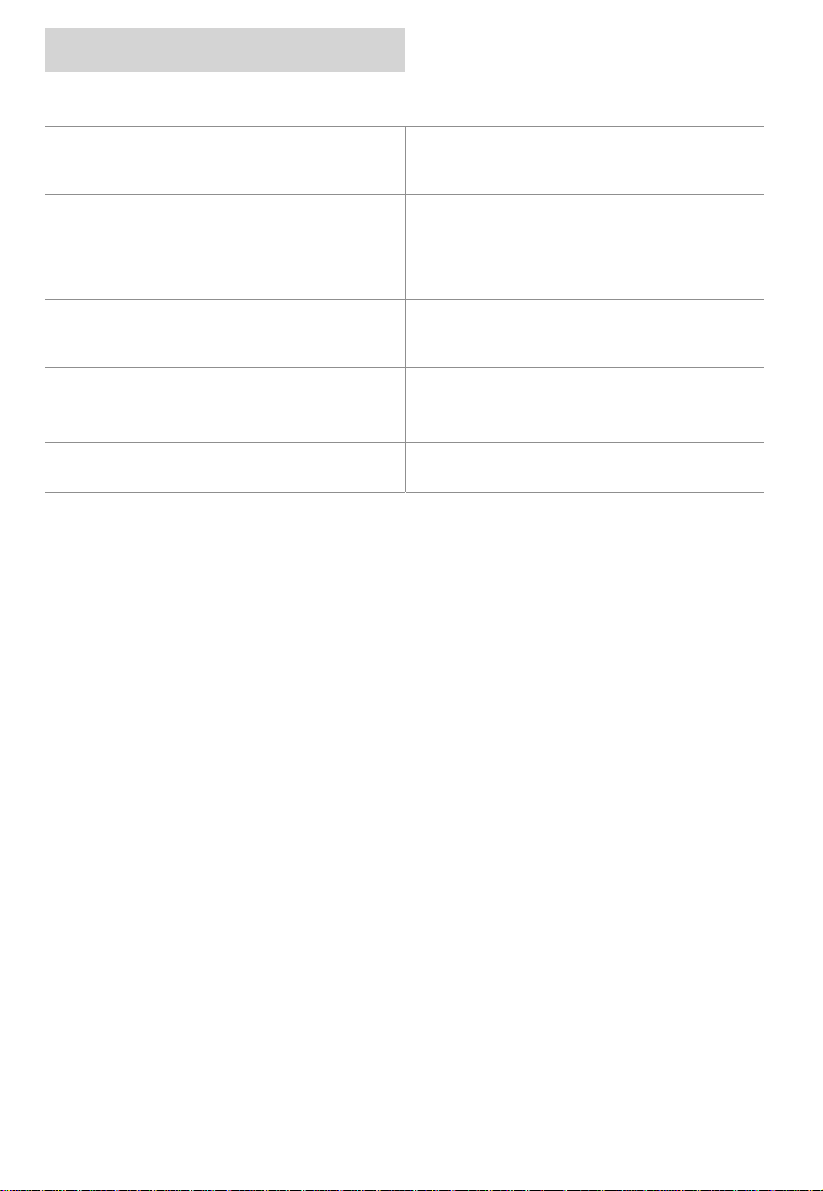
The chartplotter does not turn On
The chartplotter does not get a valid fix
The chartplotter does not turn Off
The chartplotter screen becomes very dark
after a long exposure to direct sunlight.
The chartplotter does not respond to any
command
cnd
Make sure that the correct vol tage (10-35 volt
dc) is present. Check also that the polarity is
correct.
Make sure that no metal obs tacles are placed
around the GPS antenna and that the CND has
been correctly wired. If, after 15 m inutes, the
CND does not get a fix, turn it Off and On
again.
If, after a ‘PWR’ pressure (for at least 3
seconds) the CND does not turn Of f, then turn
Off the supply.
Adjust the contrast .
‘SETUP’ + “System Settings” + ‘ENTER’ +
“Contrast” + ‘ENTER’
Try to turn Off, and then turn On.
Page 58 03/09/01
Page 59

cnd
warranty
warranty
1. Warranty
Brookes & Gatehouse Lim i ted (“B&G”) guarantees this product against defects in materials or
workmanship on the terms and conditions set out below (the “Warranty”).
2. Warranty Period
The Warranty continues for 24 months from the date of purchase by the user (excluding
mechanical items, including but not li mited to, autopilot drive units which are subject to 12 m ont hs
warranty). It is the users responsibility t o demonstrate the date of purchas e by s howing a valid
warranty card or proof of purchase. If t he user cannot do this the date of purchase shall be
deemed to be the date of m anuf acture as evidenced by the serial number of the product.
3. Repair and Replacement
During the Warranty period and subject to the terms and conditions s et out below B&G will repair
or, if it so chooses, replac e t he product. It is the user’s responsibility to arrange and pay for
transport of the product to the nearest authorized B&G representat i ve and any re-i nstallation
required following repair. B&G shall not be responsible for any such costs, including (but not
limited to):
3.1. Boat slipping or lifting;
3.2. Freight shipping charge;
3.3. Engineer’s t ravelling t i me and expenses;
3.4. Installation labour costs associated with the Warranty claims ; and
3.5. Loss or damage of products or boats i n t ransit.
4. Conditions
The Warranty will not apply in the following circumstances:
4.1. Where the product has been ins talled in a manner or location other than the that
specified in the inst al l ation instructions;
4.2. Where the product has been servi ced or repaired by anyone other than an authorized
representative;
4.3. Where the product has been used for purposes for which it is not intended;
4.4. Where the product has been used i n a manner other than that described in the manual
supplied; or
4.5. Where the damage is c aused by exceptional events such as (but not l i mited to):
o A bnormal levels of magnet i c, electrical or acous t i c interference;
o Li ght ni ng strikes;
o Accidents;
o I ntentional damage; or
o Negl i gent use.
5. Wear and Tear
The warranty is limit ed to defects in material s or workmanship and does not cover normal wear
and tear such as (but not l im it ed to) c orrosi on and dam age caus ed through t he day to day runni ng
of the boat.
03/09/01 Page 59
Page 60

warranty
cnd
warranty
6. Software
B&G shall not be liable under thi s Warranty or otherwise for any defect in software incorporated
within the product.
7. Further Warranties
The warranty set out in this document is the only warranty offered by B&G. B&G makes no furt her
promises in relation t o this product such as (but not limited to):
7.1. That i t is suitable for any partic ul ar use; or
7.2. That i t conforms to any particular quality standards.
8. Transfer
This Warranty is not transferable.
9. Consequential Loss
B&G shall not be liable for any damage to persons, yachts , equipment or any other property or for
any other kind of consequential l oss.
10. Governing Law
This document is governed by and shall be construed in accordanc e with E ngl i sh law.
11. Statuary Rights
This Warranty is offered as an extra benefit and does not affect your statutory rights against the
party who sold you the product.
Page 60 03/09/01
 Loading...