

Page 1

RADIOCOMANDO ROLLING-CODE/CONTROLLO ACCESSI
I
GB
ROLLING-CODE / ACCESS CONTROL RADIO TRANSMITTER
F
RADIOCOMMANDE ROLLING-CODE/CONTRÔLE DES ACCÈS
D
FERNSTEUERUNG MIT ROLLCODE / ZUGANGSKONTROLLE
RADIOMANDO ROLLING-CODE/CONTROL DE ACCESOS
E
RADIOCOMANDO ROLLING-CODE/CONTROLO DE ACESSOS
P
TRC 1-2-4 / MITTO 2-4 433MHz
8888
D811373 ver.02 04-04-05
8 027908 204530
RTD-CA
ISTRUZIONI D'USO E DI INSTALLAZIONE
INSTALLATION AND USER'S MANUAL
INSTRUCTIONS D'UTILISATION ET D'INSTALLATION
INSTALLATIONS-UND GEBRAUCHSANLEITUNG
INSTRUCCIONES DE USO Y DE INSTALACION
INSTRUÇÕES DE USO E DE INSTALAÇÃO
Via Lago di Vico, 44
36015 Schio (VI)
Tel.naz. 0445 696511
Tel.int. +39 0445 696533
Fax 0445 696522
Internet: www.bft.it
E-mail: sales@bft.it
Page 2

D811373_02
2
- RTD-CA - Ver. 02
Page 3

MANUALE D’USO ITALIANO
1) GENERALITÀ
Nel ringraziarVi per la preferenza accordata a questo prodotto, la ditta è certa che da esso otterrete le prestazioni necessarie al Vostro uso.
D811373_02
Leggete attentamente l’opuscolo ”Libretto istruzioni” che lo accompagna in quanto esso fornisce importanti indicazioni riguardanti la
sicurezza, l’installazione, l’uso e la manutenzione. Questo prodotto risponde alle norme riconosciute della tecnica e delle disposizioni relative
alla sicurezza. É conforme alle seguenti direttive europee: 89/336/CEE, 1999/5/CEE e modifiche successive.
Sistema radioricevente ad autoapprendimento, programmabile le cui principali caratteristiche sono:
• Ricevitore a 512 o 2048 codici
• Fino a 4 uscite (1 standard + 3 modulari) con riconoscimento automatico dei moduli inseriti
• Uscite configurabili come monostabile, bistabile, temporizzata, antiaggressione e controllo accessi
• Programmazione mediante display incorporato
• Funzioni di controllo accessi
• Capacità di riconoscere e memorizzare trasmettitori, tessere di prossimità, trasmettitori abilitati al controllo accessi.
• Compatibile con il protocollo EElink per una rapida installazione e manutenzione.
• Protezione della ricevente mediante password
2) MANUTENZIONE
La manutenzione dell’impianto va fatta eseguire regolarmente da parte di personale qualificato.
Le trasmittenti MITTO sono alimentate da 2 batterie al litio da 3V (tipo CR2016).
Le trasmittenti TRC sono alimentate da una batteria alcalina da 12V.
Una diminuzione della portata della trasmittente può essere dovuta alle batterie che si stanno scaricando. Quando il led della trasmittente
lampeggia, indica che le batterie sono scariche e devono essere sostituite.
3) DEMOLIZIONE
ATTENZIONE: Avvalersi esclusivamente di personale qualificato.
L’eliminazione dei materiali va fatta rispettando le norme vigenti. Nel caso di demolizione del sistema, non esistono particolari pericoli o rischi
derivanti dai componenti stessi. È opportuno, in caso di recupero dei materiali, che vengano separati per tipologia (parti elettriche - rame alluminio - plastica - ecc.). Per lo smaltimento della batteria riferirsi alla normativa vigente.
USER’S MANUAL
1) GENERAL OUTLINE
Thank you for buying this product, our company is sure that you will be more than satisfied with the performance of the product. Read the
“Instruction Manual” supplied with this product carefully, as it provides important information about safety, installation, operation and
maintenance.This product conforms to recognised technical standards and safety regulations. It complies with the 89/336/EEC, 1999/5/CEE,
European Directive and subsequent amendments.
Programmable self-learning radio receiver system, having the following main features:
• Receiver with 512 or 2048 codes
• Up to 4 outputs (1 standard + 3 modular) with automatic recognition of the modules entered
• Outputs which can be configured as monostable, bistable, timed, anti-aggression and access control
• Programming by means of incorporated display
• Access control functions by means of integrated WRTD board
• Capable of recognising and memorising transmitters, proximity cards, and transmitters enabled for access control
• Compatible with EElink protocol for fast installation and maintenance
• Protection of receiver by means of password.
2) MAINTENANCE
The maintenance of the system should only be carried out by qualified personnel regularly.
The MITTO transmitters are supplied by two 3V lithium battiers (type CR2016).
The TRC transmitters are powered by a 12V alkaline battery.
Any reduction in the transmitter capacity may be due to the batteries getting flat.
When the led of the transmitter flashes, it means that the batteries are flat and must be replaced.
3) DISPOSAL
ATTENTION: disposal should only be carried out by qualified personnel.
Materials must be disposed of in conformity with the current regulations. In case of disposal, the system components do not entail any particular
risks or danger. In case of recovered materials, these should be sorted out by type (electrical components, copper, aluminium, plastic etc.).
For battery disposal, refer to the current regulations.
ENGLISH
RTD-CA - Ver. 02 -
3
Page 4

FRANÇAIS
1) GÉNÉRALITÉS
Nous vous remercions pour avoir choisi ce produit. Nous sommes sûrs qu’il vous rendra le service nécessaire à vos besoins. Lire attentivement
le «Manuel d’instructions» qui accompagne ce produit puisqu’il fournit d’importantes indications concernant la sécurité, l’installation,
l’utilisation et l’entretien.
Ce produit est conforme aux normes reconnues de la technique et aux dispositions concernant la sécurité. Ce produit est conforme aux normes
reconnues de la technique et des dispositions concernant la sécurité. Il est également conforme aux directives européennes suivantes: 89/
336/CEE, 1999/5/CEE et modifications successives.
Système radio récepteur à autoapprentissage, programmable, dont les caractéristiques principales sont:
• Récepteur à 512 ou 2048 codes.
• Jusqu’à 4 sorties (1 standard + 3 modulaires) avec reconnaissance automatique des modules insérés.
• Sorties configurables comme monostable, bistable, temporisée, anti-agression et contrôle des accès.
• Programmation avec écran incorporé.
• Fonctions Contrôle des Accès par carte WRTD intégrée.
• Capacité de reconnaître et de mémoriser des émetteurs, des badges sans contact, des émetteurs activés pour le contrôle des accès.
• Compatible avec le protocole EElink pour une installation et une maintenance rapides.
• Protection du récepteur avec mot de passe.
2) ENTRETIEN
L’entretien de l’installation doit être effectué régulièrement de la part de personnel qualifié.
Les émetteurs MITTO sont alimentés par 2 batteries au lithium de 3V (type CR2016).
Les émetteurs TRC sont alimentés par une pile alcaline 12V.
Une réduction de la portée de l’émetteur peut être due aux batteries en train de se décharger.
Quand la led de l’émetteur clignote, cela indique que les batteries sont à plat et qu’il faut les remplacer.
3) DÉMOLITION
ATTENTION: s’adresser uniquement à du personnel qualifié. L’élimination des matériaux doit être faite en respectant les normes en
vigueur.
En cas de démolition du système, il n’existe aucun danger ou risque particulier dérivant de ses composants. En cas de récupération des
matériaux, il sera opportun de les trier selon leur genre (parties électriques - cuivre - aluminium - plastique - etc.). Pour l’élimination de la batterie,
se référer aux normes en vigueur.
MANUEL D’UTILISATION
D811373_02
DEUTSCH
1) ALLGEMEINES
Wir danken Ihnen, daß Sie sich für diese Anlage entschieden haben. Ganz sicher wird sie mit ihren Leistungen Ihren Ansprüchen vollauf gerecht
werden. Lesen Sie aufmerksam die Broschüre mit den “GEBRAUCHSANWEISUNGEN“ durch, die dem Produkt beiliegen. Sie enthält wichtige
Hinweise zur Sicherheit, Installation, Bedienung und Wartung der Anlage. Dieses Produkt genügt den anerkannten technischen Normen und
Sicherheitsbestimmungen. Dieses Produkt entspricht den anerkannten technischen Regeln und Sicherheitsbestimmungen. Es genügt der
Europäischen Richtlinie 89/336/EWG , 1999/5/EWG, und nachfolgenden Änderungen.
Funkempfangsanlage mit Selbstlerntechnik, programmierbar, mit folgenden Hauptmerkmalen:
• Empfänger mit 512 oder 2048 Codes
• Bis zu 4 ausgänge (1 standard + 3 modular) mit automatischen Erkennung der einbezogenen Module.
• Ausgänge konfigurierbar als monostabil, bistabil, zeitgeschaltet, für Aggressionssicherung und Zugangskontrolle.
• Programmierung am eingebauten Display.
• Betrieb mit festem und variablem Code.
• Zugangskontrollfunktionen mittels integrierter Karte WRTD
• Möglichkeit zur Erkennung und Speicherung von Sendern, kontaktlosen Ausweiskarten und Sendern, die für die Zugangskontrolle aktiviert
sind.
• Kompatibel mit dem Protokoll EElink für eine schnelle Installation und Wartung.
• Paßwortschutz des Empfängers.
2) WARTUNG
Die Anlagenwartung ist regelmäßig von Fachleuten vorzunehmen.
Die Sender MITTO werden von 2 Litiumbatterien mit 3 V gespeist (Typ CR2016).Die Handsender TRC werden von einer 12v Alkaline Batterie
betrieben. Wenn die Reichweite des Senders abnimmt, kann es sein, daß die Batterien fast leer sind. Blinkt die LED des Senders, sind die
Batterien leer und müssen erneuert werden.
3) ENTSORGUNG
ACHTUNG: Diese Tätigkeit ist fachkundigen Personen vorbehalten.
Die Materialien sind unter Beachtung der geltenden Vorschriften zu entsorgen. Bei der Entsorgung des Systems bestehen keine besonderen,
von den Komponenten ausgehenden Gefahren oder Risiken. Es ist sinnvoll, nach Materialarten zu sortieren und die Stoffe einer getrennten
Entsorgung zuzuführen (Elektrische Komponenten - Kupfer - Aluminium - Plastik - usw.). Bei der Batterieentsorgung sind die geltenden
Vorschriften zu beachten.
4
- RTD-CA - Ver. 02
BEDIENUNGSANLEITUNG
Page 5

MANUAL DE USO
1) GENERALIDADES
Al agradecerle la preferencia que ha manifestado por este producto, la empresa está segura de que de él obtendrá las prestaciones necesarias
D811373_02
para sus exigencias. Lea atentamente el “Manual de Instrucciones” que lo acompaña, pues proporciona importantes indicaciones referentes
a la seguridad, la instalación, el uso y el mantenimiento. Este producto responde a las normas reconocidas de la técnica y a las disposiciones
relativas a la seguridad, y es conforme a las siguientes directivas europeas: 89/336/CEE, 1999/5/CEE y modificaciones sucesivas.
Sistema radiorreceptor con función de autoaprendizaje, programable, cuyas principales características son:
• Receptor de 512 ó 2048 códigos.
• Hasta 4 salidas (1 standard + 3 modulares) con reconocimiento automático de los módulos introducidos.
• Salidas configurables como monoestable, biestable, temporizada, antiagresión y control de accesos.
• Programación mediante display incorporado.
• Funciones de Control de Accesos mediante tarjeta WRTD integrada.
• Capacidad de reconocer y memorizar transmisores, tarjetas de proximidad, transmisores habilitados para el control de accesos.
• Compatible con el protocolo EElink, para agilizar la instalación y el mantenimiento.
• Protección del receptor mediante contraseña.
2) MANTENIMIENTO
El mantenimiento de la instalación debe ser realizado, con regularidad, por personal cualificado.
Los transmisores se alimentan mediante dos baterías al litio de 3V (tipo CR2016).
Los transmisores TRC están alimentados por una batería Alcalina de 12V.
Una disminución de la capacidad del transmisor puede deberse a las baterías que se están descargando.
Cuando el led del transm isor está parpadeando, indica que las baterías se encuentran descargadas y que deben sustituirse.
3) DEMOLICION
ATENCION: Hay que servirse exclusivamente de personal cualificado. La eliminación de los materiales debe hacerse respetando las
normas vigentes. En el caso de demolición del sistema, no existen particulares peligros o riesgos que deriven de los componentes. Es
conveniente, en caso de recuperación de los materiales, que éstos se separen por tipos (partes eléctricas, cobre, aluminio, plástico, etc.). Por
lo que respecta a la eliminación de la batería, hay que respetar la normativa vigente.
ESPAÑOL
MANUAL PARA DE USO
1) GENERALIDADES
Agradecendolhe pela preferência dada a este produto, a Empresa tem a certeza que do mesmo obterá as prestações necessárias para o uso
que entende fazer. Leia atentamente o “Manual de instruções “que acompanha este produto, pois que esse fornece indicações importantes
respeitantes a segurança, a instalação, a utilização e a manutenção. Este produto responde às normas reconhecidas pela técnica e pelas
disposições relativas à segurança.
Este produto responde às normas reconhecidas da técnica e das disposições relativas à segurança. Está em conformidade com as seguintes
directivas europeias: 89/336/CEE, 1999/5/CEE e modificações sucessivas.
Sistema radiorreceptor de autoaprendizagem, programável, cujas características principais são:
• Receptor com 512 ou 2048 códigos
• Até 4 saídas (1 standard + 3 modulares) com reconhecimento automático dos módulos inseridos.
• Saídas configuráveis como monoestável, biestável, temporizada, anti-agressão e controlo de acessos
• Programação por meio de visor incorporado
• Funções de Controlo de acessos por meio da placa WRTD integrada
• Capacidade de reconhecer e armazenar transmissores, cartões de proximidade, transmissores autorizados ao controlo de acessos.
• Compatível com o protocolo EElink para uma rápida instalação e manutenção.
• Protecção do receptor por meio de password
2) MANUTENÇÃO
A manutenção da instalação deve ser executada periodicamente por pessoal qualificado.
Os transmissores são alimentados por 2 baterias de lítio de 3V (tipo CR2016).
Os emissores TRC são alimentados por uma bateria alcalina de 12V.
Uma diminuição do alcance do transmissor pode ser devida ao facto que as baterias se estão a descarregar.
Quando o led do transmissor pisca, indica que as baterias estão descarregadas e devem ser substituídas.
3) DESTRUIÇÃO
ATENÇÃO: Servir-se exclusivamente de pessoal qualificado. A eliminação dos materiais deve ser feita respeitando-se as normas vigentes.
No caso de destruição do sistema, não existem perigos particulares ou riscos derivantes dos próprios componentes. No caso de recuperação
dos materiais é oportuno, separálos por tipo (partes eléctricas - cobre - alumínio - plástico - etc.). Para a eliminação da bateria referir-se à norma
vigente.
PORTUGUÊS
RTD-CA - Ver. 02 -
5
Page 6

ITALIANO
MANUALE PER L’INSTALLAZIONE
Nel ringraziarVi per la preferenza accordata a questo prodotto, la ditta
è certa che da esso otterrete le prestazioni necessarie al Vostro uso.
Leggete attentamente l’opuscolo “Avvertenze” ed il “Libretto istru-
zioni” che accompagnano questo prodotto in quanto forniscono
importanti indicazioni riguardanti la sicurezza, l’installazione, l’uso e la
manutenzione. Questo prodotto risponde alle norme riconosciute
della tecnica e della disposizioni relative alla sicurezza. Confermiamo
che è conforme alle seguenti direttive europee: 89/336/CEE, 73/23/
CEE (e loro modifiche successive).
SICUREZZA GENERALE
ATTENZIONE! Una installazione errata o un uso improprio del
prodotto, può creare danni a persone, animali o cose.
• Leggete attentamente l’opuscolo ”Avvertenze” ed il ”Libretto
istruzioni” che accompagnano questo prodotto, in quanto forni-
scono importanti indicazioni riguardanti la sicurezza, l’installazione, l’uso e la manutenzione.
• Smaltire i materiali di imballo (plastica, cartone, polistirolo, ecc.)
secondo quanto previsto dalle norme vigenti. Non lasciare buste
di nylon e polistirolo a portata dei bambini.
• Conservare le istruzioni per allegarle al fascicolo tecnico e per
consultazioni future.
• Questo prodotto è stato progettato e costruito esclusivamente per
l’utilizzo indicato in questa documentazione. Usi non indicati in
questa documentazione potrebbero essere fonte di danni al
prodotto e fonte di pericolo.
• La Ditta declina qualsiasi responsabilità derivante dall’uso improprio o diverso da quello per cui è destinato ed indicato nella
presente documentazione.
• Non installare il prodotto in atmosfera esplosiva.
• Gli elementi costruttivi della macchina devono essere in accordo
con le seguenti Direttive Europee: 89/336/CEE, 1999/5/CEE e
modifiche successive. Per tutti i Paesi extra CEE, oltre alle norme
nazionali vigenti, per un buon livello di sicurezza è opportuno
rispettare anche le norme sopracitate.
• La Ditta declina qualsiasi responsabilità dall’inosservanza della
Buona Tecnica nella costruzione delle chiusure (porte, cancelli,
ecc.), nonché dalle deformazioni che potrebbero verificarsi durante l’uso.
• L’installazione deve essere in accordo con quanto previsto dalle
Direttive Europee: 89/336/CEE, 1999/5/CEE e modifiche successive.
• Togliere l’alimentazione elettrica, prima di qualsiasi intervento
sull’impianto. Scollegare anche eventuali batterie tampone se
presenti.
• Prevedere sulla rete di alimentazione dell’automazione, un interruttore o un magnetotermico onnipolare con distanza di apertura
dei contatti uguale o superiore a 3,5 mm.
• Verificare che a monte della rete di alimentazione, vi sia un
interruttore differenziale con soglia da 0.03A.
• Verificare se l’impianto di terra è realizzato correttamente: collegare tutte le parti metalliche della chiusura (porte, cancelli, ecc.)
e tutti i componenti dell’impianto provvisti di morsetto di terra.
• Applicare tutti i dispositivi di sicurezza (fotocellule, coste sensibili,
ecc.) necessari a proteggere l’area da pericoli di schiacciamento,
convogliamento, cesoiamento.
• Applicare almeno un dispositivo di segnalazione luminosa (lampeggiante) in posizione visibile, fissare alla struttura un cartello di
Attenzione.
• La Ditta declina ogni responsabilità ai fini della sicurezza e del
buon funzionamento dell’automazione se vengono impiegati componenti di altri produttori.
• Usare esclusivamente parti originali per qualsiasi manutenzione
o riparazione.
• Non eseguire alcuna modifica ai componenti dell’automazione se
non espressamente autorizzata dalla Ditta.
• Istruire l’utilizzatore dell’impianto per quanto riguarda i sistemi di
comando applicati e l’esecuzione dell’apertura manuale in caso di
emergenza.
• Non permettere a persone e bambini di sostare nell’area d’azione
dell’automazione.
• Non lasciare radiocomandi o altri dispositivi di comando alla
portata dei bambini onde evitare azionamenti involontari dell’automazione.
6
- RTD-CA - Ver. 02
• L’utilizzatore deve evitare qualsiasi tentativo di intervento o riparazione dell’automazione e rivolgersi solo a personale qualificato.
• Tutto quello che non è espressamente previsto in queste istruzioni, non è permesso.
• L’installazione deve essere fatta utilizzando dispositivi di sicurezza e comandi conformi alla EN 12978.
1) GENERALITÀ
Sistema radioricevente ad autoapprendimento, programmabile le cui
principali caratteristiche sono:
• Ricevitore a 512 o 2048 codici
• Fino a 4 uscite (1 standard + 3 modulari) con riconoscimento
automatico dei moduli inseriti
• Uscite configurabili come monostabile, bistabile, temporizzata,
antiaggressione e controllo accessi
• Programmazione mediante display incorporato
• Funzioni Controllo Accessi mediante scheda WRTD integrata
• Capacità di riconoscere e memorizzare trasmettitori, tessere di
prossimità, trasmettitori abilitati al controllo accessi.
• Compatibile con il protocollo EElink per una rapida installazione
e manutenzione.
• Protezione della ricevente mediante password
L’integrazione del sistema ricevente dotato di clonazione dei trasmettitori con il sistema controllo accessi consente una vasta tipologia di
installazioni.
Consente di gestire fino a 4 varchi di accesso utilizzando sia radiotrasmettitori (MITTO/TRC) che transponder (Compass-Isocard/CompassRing/MITTO T).
I radiotrasmettitori (MITTO/TRC), possono essere gestiti dal sistema
RTD-CA sia come radiotrasmettitori tradizionali, sia come tessere di
prossimità.
Utilizzando una interfaccia opzionale COMPASS-232, il sistema può
essere monitorato dal software di controllo accessi SECURBASE
(opzionale) che consente un completo controllo degli accessi.
Il controllo del varco viene gestito da un’uscita con contatto N.O.; nel
caso si renda necessario è possibile incrementare il numero di uscite
mediante appositi moduli opzionali, che consentono di ottenere un
massimo di 4 canali di uscita, configurabili in modo indipendente.
2) DATI TECNICI
2.1)Ricevitore RTD-CA
Alimentazione: ...................................................... 230V ±10%50Hz
Frequenza: ..................................................................... : 433.92MHz
Temperatura di funzionamento ..................................... : -20 / +55°C
Codice a mezzo: ............................................. Algoritmo rolling-code
N°combinazioni: ................................................................... 4 miliardi
Impedenza antenna: .................................................. 50Ohm (RG58)
Dimensioni: ....................................................................... vedere fig.1
Contatto relè: ....................................................................0,5A - 12V=
Grado di protezione: ................................................................. IP 20*
(*) Il grado di protezione dell’involucro diviene IP55 utilizzando un
accessorio fornibile a richiesta. Utilizzare solo raccordi adatti alle
dimensioni del contenitore e al diametro del cavo.
2.2) Scheda WRTD
• Accesso a tessera di prossimità/trasmettitori abilitati
• I parametri di sistema e la mappa codici sono memorizzati in una
memoria non volatile, che può conservare i dati inseriti per anni
anche in assenza di alimentazione elettrica.
• La memoria può gestire fino a 819 tessere (RTD-CA 512) o 2500
tessere (RTD-CA 2048).
• Il tempo di apertura porta può essere liberamente impostato da 0
a 25,5 secondi.
• Il tempo di controllo porta aperta può essere liberamente impostato da 0 a 255 secondi.
2.3) Trasmettitore MITTO
Tasti: ................................................................................Colore giallo
Alimentazione: ............................. 2 Pile al Litio da 3V (tipo CR2016)
Portata: ..........................................................................50 / 100 metri
Versioni trasmettitori:
MITTO2 - bicanale, MITTO4 - quadricanale.
2.4) Trasmettitore TRC
Tasti: ............................................................................... Colore rosso
Alimentazione: ......................................................... Pila Alkalina 12V
D811373_02
Page 7

MANUALE PER L’INSTALLAZIONE
ITALIANO
Portata: .......................................................................... 50 / 100 metri
Versioni trasmettitori:
D811373_02
TRC1-monocanale, TRC2-bicanale, TRC4-quadricanale.
Accessori (opzionali):
COMPASS-READER:
Lettore tessere di prossimità.
COMPASS-ISOCARD:
Tessera di prossimità standard ISO, con possibilità di personalizzazione
(foto, dati anagrafici, ecc.)
COMPASS-RING:
Portachiavi con transponder, dotato delle stesse funzionalità della
tessera.
MITTO2-T/MITTO4-T:
Trasmettitore rolling-code con transponder, dotato delle stesse funzionalità della tessera.
COMPASS-232:
Convertitore seriale per collegare fino a 19 RTD-CA alla porta seriale
del PC.
SECURBASE:
Database di gestione controllo accessi su PC.
Funzioni principali: anagrafica tessere, anagrafica lettori, fasce orarie,
calendario, antipassback, autoapprendimento tessere.
ATTENZIONE: Il software può gestire un massimo di 20 uscite
configurate nella ricevente come controllo accessi. Il numero massimo di RTD-CA gestibili dipende quindi da quante uscite di ogni
ricevente sono state configurate come controllo accessi.
MOP
Modulo ad innesto dotato di uscita aggiuntiva contatto N.O.
3) INSTALLAZIONE
Dopo aver predisposto il passaggio dei cavi di collegamento procedere al fissaggio del supporto (fig.1), segnando i due fori utilizzando le
due asole a disposizione sul contenitore come dima. In base al
materiale di cui è costituito il supporto usare direttamente le viti in
dotazione oppure forare con una punta di diametro 4mm per inserire
i tasselli in dotazione.
Avvitare completamente le viti compensando eventuali errori di
centraggio utilizzando le asole del contenitore.
ATTENZIONE! La scheda di controllo RTD-CA comanda tramite
relè l’apertura della porta.
Una installazione di sicurezza prevede pertanto il posizionamento
della scheda RTD-CA all’interno dell’edificio in area protetta da
effrazione.
Eventuali lettori transponder Compass-Reader possono essere posizionati all’esterno dell’edificio dato che anche in caso di manomissione non possono comandare l’apertura della porta.
4) SCHEMA DI COLLEGAMENTO
Sono possibili vari tipi di installazioni a seconda del numero di uscite
disponibili e delle funzionalità richieste dal sistema.
La Fig. 2 rappresenta le morsettiere presenti nella ricevente RTD-CA
e nel modulo controllo accessi WRTD.
La Fig. 3 rappresenta lo schema di cablaggio di un impianto tipo.
La Fig. 4 rappresenta le connessioni necessarie tra RTD-CA, Compass232 e Compass-Reader in impianti gestiti da Securbase.
RTD-CA
JP4
1-2
Ingresso alimentazione 230 V ±10% 50/60Hz(1L-2N)
JP3
3 - Uscita Contattto Comune COM
4 - Uscita Contatto normalmente aperto NO
Contatto per pilotaggio apertura porta.
JP2
5 - 6 Ingresso antenna (5 segnale - 6 calza).
WRTD
JP6 (connessione COMPASS-READER)
1 + Alimentazione
2D1
3DØ
4 0 Alimentazone
5 LED A
6 LED B
Riceve dal COMPASS-READER i dati della tessera presentata.
E’ possibile collegare un massimo di 2 Compass-Reader in parallelo
ad ogni WRTD.
JP3
7-8 Seriale RS 485 (7-B, 8-A)
Consentono la connessione seriale di più RTD-CA nei sistemi
interfacciati tramite Compass-232 alla porta seriale COM di un PC. Si
consiglia di non superare i 500 m di lunghezza massima di connessione.
JP5
13-12 Ingresso stato porta OUT1 (N.C.)
13-11 Ingresso stato porta OUT2 (N.C.)
13-10 Ingresso stato porta OUT3 (N.C.)
13-9 Ingresso stato porta OUT4 (N.C.)
Ingressi di verifica dello stato di chiusura della porta.
JP4
14-15-16 Allarme 14-NC, 15-NO, 16-COM
Contatto di scambio per pilotaggio allarme, dopo l’apertura della porta,
se questa non viene richiusa entro il “tempo di controllo porta aperta”
impostato, avviene la commutazione tra NC e NO.
MOP (opzionale)
JP1
1-2 Uscita Contatto normalmente aperto NO. Contatto per pilotaggio
apertura porta
INSTALLAZIONE ANTENNA
Usare una antenna accordata sui 433MHz.
Per il collegamento Antenna-Ricevitore usare cavo coassiale RG58.
La presenza di masse metalliche a ridosso dell’antenna, può
disturbare la ricezione radio. In caso di scarsa portata del trasmettitore, spostare l’antenna in un punto più idoneo.
5) PROGRAMMAZIONE
La ricevente RTD-CA unisce alle funzioni di radioricevente le funzioni
di controllo accessi.
Se una uscita viene configurata come controllo accessi, automaticamente il menu aggiungi viene settato per ricevere tessere o trasmettitori da abilitare e gestire nella modalità controllo accessi.
Nel caso si desideri utilizzare dei trasmettitori (MITTO/TRC) come
tessere controllo accessi occorre tenere presente che ad ogni tasto
(T1, T2, T3, o T4) corrisponde un codice tessera.
Risulta così possibile una vasta tipologia di installazioni dove ogni
ricevente RTD-CA può avere delle uscite configurate come controllo
accessi e delle uscite configurate come radiocomando.
A titolo di esempio l’impianto schematizzato in Fig.3 è così configurato:
OUT1 - Uscita radiocomando standard abbinata al tasto T1
OUT2 - Uscita radiocomando standard abbinata al tasto T2
OUT3 - Uscita controllo accessi abbinata al tasto T3 del trasmettitore
che in questo caso è stato memorizzato come trasmettitore abilitato al
controllo accessi. La ricezione del codice tessera avviene via radio.
OUT4 - Uscita controllo accessi controllata da un Compass-Reader.
Questo varco viene controllato da tessere di prossimità (CompassIsocard/Compass-Ring) o dal transponder presente nel MITTO T.
Nel caso di installazioni complesse si consiglia di realizzare
preventivamente uno schema di cablaggio generale dell’impianto.
In questi tipi di installazione il posizionamento dell’antenna dovrà
essere fatto con particolare attenzione, tenendo presente che i trasmettitori possono controllare più di un varco, purchè si trovino
nell’area di ricezione dell’antenna.
NOTA: Un trasmettitore per essere abilitato e gestito dal sistema controllo accessi della RTD-CA deve essere necessariamente un clone del primo trasmettitore inserito (vedi paragrafo 5.1).
La clonazione di un trasmettitore non comporta l’attivazione
automatica delle uscite configurate in modalità radiocomando
(uscite OUT1 e OUT2 dell’esempio). Questi trasmettitori dovranno essere inseriti manualmente nella ricevente.
5.1)TRASMETTITORI ABILITATI AL CONTROLLO ACCESSI
Per abilitare i trasmettitori al funzionamento come controllo accessi è
possibile seguire una di queste due procedure:
Se nella ricevente non è stato inserito nessun trasmettitore:
Inserire un primo trasmettitore in una uscita a scelta, purchè non
configurata come controllo accessi, in modo da assegnare un codice
ricevitore alla RTD-CA. Successivamente, mediante UNIRADIO, clonare
RTD-CA - Ver. 02 -
7
Page 8

ITALIANO
MANUALE PER L’INSTALLAZIONE
questo primo trasmettitore “master” per ottenere tutti i trasmettitori da
inserire successivamente nella gestione controllo accessi.
Fare riferimento al menu “configurazione”, al menu “aggiungi” e al
paragrafo 6 “clonazione per aggiunta con master”.
NOTA IMPORTANTE: CONTRASSEGNARE IL PRIMO TRASMETTITORE MEMORIZZATO CON IL BOLLINO CHIAVE (MASTER).
Se nella ricevente è già stato inserito un trasmettitore chiave e
questo non è disponibile:
Leggere mediante UNIRADIO il codice inserito nella ricevente (vedi
paragrafo 6 “lettura codice”), successivamente come indicato nel paragrafo “clonazione per aggiunta con codice” ottenere tutti i trasmettitori
da inserire successivamente nella gestione controllo accessi.
Il numero di codice assegnato, consentirà in qualsiasi momento
la creazione e la clonazione di altri trasmettitori abilitati, si
consiglia quindi di annotarlo sull’apposita tessera fornita e consegnarla all’utente (Fig.7).
Fare riferimento alle Istruzioni UNIRADIO per ulteriori informazioni.
5.2) DESCRIZIONE DEI MENU DI PROGRAMMAZIONE:
Aggiungi:
Consente di aggiungere nella memoria del ricevitore un trasmettitore,
una tessera o un trasmettitore abilitato al controllo accessi.
Sono possibili due modalità:
Auto: il trasmettitore o la tessera viene inserita nella prima
locazione di memoria libera disponibile.
Manuale: viene richiesto il numero della locazione di memoria
nella quale inserire il trasmettitore o la tessera. Questa modalità
si rivela utile nel caso si desideri attribuire un numero progressivo
ai vari trasmettitori/tessere, in modo da semplificare una eventuale successiva eliminazione dalla memoria della ricevente.
Dopo aver selezionato la modalità automatica o manuale è necessario:
1) Selezionare, con i pulsanti + e - l’uscita che si desidera attivare.
2) Se l’uscita è configurata come monostabile, bistabile, temporizzata
o antiaggressione (menu aggiungi 1 Fig.A):
Premere il tasto nascosto P1 del trasmettitore e successivamente
premere il tasto (T1,T2,T3 o T4) del trasmettitore che si desidera
abbinare all’uscita precedentemente selezionata
3) Se l’uscita è configurata come controllo accessi (menu aggiungi
2 Fig.A):
Presentare al Compass-Reader una tessera da abilitare o premere un tasto (T1, T2, T3 o T4) di un trasmettitore abilitato (vedi
paragrafo “TRASMETTITORI ABILITATI AL CONTROLLO ACCESSI”)
Nota: Il tasto nascosto P1 assume aspetto diverso a seconda del
modello di trasmettitore.
Per TRC 1-2 / MITTO 2-4, premere il pulsante nascosto P1 (Fig.B1A).
Per TRC 4, il tasto P1 corrisponde alla pressione contemporanea dei
4 tasti del trasmettitore o, aprendo il vano batteria, a ponticellare con
un cacciavite le due piazzole P1 (Fig.B2 A).
Cancella:
Consente di cancellare dalla memoria del ricevitore uno o tutti i
trasmettitori/tessere inseriti.
Codice: consente di eliminare un trasmettitore/tessera dalla
memoria della ricevente inserendo il numero di posizione in
memoria (vedi menu aggiungi-manuale).
Database: consente di eliminare TUTTI i trasmettitorie e
transponder dalla memoria della ricevente. Viene richiesta conferma dell’operazione per evitare cancellazioni involontarie.
Nota: in questo menu le trasmittenti vengono indicate con la lettera “R”
(es. R002), le tessere ed i radiocomandi abilitati vengono indicati con
la lettera “T” (es. T012).
Verifica:
Consente di verificare la presenza in memoria di un trasmettitore/
tessera o di visualizzarne l’elenco completo.
Leggi codice: richiede la pressione di un tasto del trasmettitore
o la presentazione della tessera o del radiocomando abilitato. Se
memorizzato visualizza il numero di locazione ed il numero del
tasto nel caso di trasmettitori o nel caso di tessere/trasmettitori
abilitati il numero di locazione seguito dal messaggio “transp”.
Scorri lista: utilizzando i pulsanti + e - risulta possibile scorrere
l’elenco di tutti i tasmettitori/tessere memorizzate, la pressione
prolungata del tasto accellera lo scorrimento della lista.
8
- RTD-CA - Ver. 02
Uscite:
Consente di configurare il comportamento delle uscite presenti nel
ricevitore.
Configura uscita 1,2,3,4: selezionare l’uscita che si desidera
configurare utilizzando i pulsanti + e -.
Ogni uscita può essere configurata secondo queste modalità:
1) impulsivo (monostabile) Il relè dell’uscita abbinata resta
attratto finché il relativo tasto del trasmettitore rimane premuto
2) passo passo (bistabile) (il relè dell’uscita abbinata cambia
stato ad ogni pressione del tasto del trasmettitore)
3) temporizzato (ad ogni pressione del tasto della trasmittente,
il relè dell’uscita resta attratto per 90 secondi. Pressioni del tasto
durante il ciclo di conteggio reinizializzano il conteggio stesso).
4) antiaggressione (il relè dell’uscita abbinata cambia stato se
la pressione del tasto del trasmettitore ha una durata superiore a
5 secondi). Tutti i tasti di tutti i trasmettitori inseriti nella ricevente
sono automaticamente dotati della funzione antiaggressione indipendentemente dalla loro configurazione, pertanto l’assegnazione di un tasto (T1,T2,T3 oT4) all’uscita non è necessario.
La commutazione del relè ha una durata di 10s.
5) controllo accessi (il relè dell’uscita abbinata cambia stato
solo a seguito della presentazione di una tessera abilitata o della
ricezione di un codice trasmettitore abilitato).
Il settaggio di un’uscita in modalità controllo accessi richiede la
successiva configurazione dei seguenti parametri:
Tipo accesso:
con PC: l’uscita viene configurata per essere gestita dal software
controllo accessi Securbase (Fig 4-5). Il riconoscimento e l’abilitazione di una tessera o di un trasmettitore abilitato vengono
effettuati in remoto.
stand alone: l’uscita viene configurata per essere gestita senza
software Securbase. Il riconoscimento e l’abilitazione di una
tessera o di di un trasmettitore abilitato vengono effettuati dalla
ricevente RTD-CA.
libero: l’uscita cambia stato alla ricezione di qualsiasi codice
tessera (abilitata o non abilitata)
vietato: l’uscita viene bloccata (porta sempre chiusa)
lettore di sistema: da utilizzare nel caso di presenza del software
Securbase. Se configurata come lettore di sistema la ricevente
viene predisposta per l’inserimento sequenziale di tessere e
trasmettitori abilitati. Per motivi di praticità si consiglia di settare
come lettore di sistema una ricevente RTD-CA dotata di un lettore
Compass-Reader posizionato in prossimità del PC.
Per l’inserimento sequenziale di trasmettitori abilitati è indispensabile configurare una RTD-CA come lettore di sistema
Tempo relè porta:
incrementare o decrementare con i tasti +/- il valore del tempo di
attrazione del relè porta a seguito della ricezione di una tessera o
di un trasmettitore valido. Il valore è espresso in decimi di
secondo, variabile da 0 a 25,5 s. Se il valore viene impostato a 0
il relè resta attratto fino a che la porta non viene richiusa.
Tempo controllo porta:
incrementare o decrementare con i tasti +/- il valore del tempo di
controllo porta. Il valore è espresso secondi, variabile da 0 a 255
s. Se entro questo tempo non viene chiuso il contatto di controllo
stato porta corrispondente all’uscita, avviene la commutazione
del relè allarme che persiste fino alla chiusura del contatto.
Se il tempo di controllo porta viene settato a 0 la funzione viene
disabilitata.
Indirizzo:
impostare utilizzando i tasti +/- l’indirizzo di comunicazione (polling)
sulla linea seriale 485. Da utilizzare nel caso di più di una uscita
controllo accessi connessa alla linea seriale. Ogni uscita
configurata come controllo accessi dovrà avere un indirizzo
univoco compreso da 0 a 19. La presenza di due uscite con lo
stesso indirizzo provoca conflitti software. L’indirizzo di defalut è
1 per l’uscita 1, 2 per l’uscita 2, 3 per l’uscita 3, 4 per l’uscita 4.
L’indirizzo è ininfluente nel caso di sistemi stand-alone.
Note:
1) Le uscite di default sono configurate come monostabili. Solo
un’uscita può essere configurata in modalità antiaggressione.
2) Nel caso sia necessario verificare in quale modalità sia stata
D811373_02
Page 9

MANUALE PER L’INSTALLAZIONE
ITALIANO
configurata un’uscita, selezionarla e premere il tasto OK. La
ricevente visualizza come prima opzione la modalità di funziona-
D811373_02
mento precedentemente settata.
3) Se si cerca di configurare un’uscita non dotata di modulo opzionale
MOP verrà visualizzato il messaggio di errore “modulo non presente”
4) In caso di anomalie di funzionamento del PC o comunque in ogni
caso di assenza di comunicazione tra Securbase e RTD-CA,
rimangono comunque attive le funzionalità stand-alone della
ricevente RTD-CA, che può in ogni caso verificare le tessere
registrate nella propria memoria. Si consiglia quindi di copiare le
tessere di uso più frequente o più importanti dal database di
Securbase alla memoria della RTD-CA. Fate riferimento alle
istruzioni Securbase per ulteriori informazioni.
5) La seguente tabella riporta la capacità di memoria delle versioni:
RTD-CA N° max. Tessere o N° max Totale
512 819 512 819
2048 2500 2048 3270
Ogni memorizzazione occupa una locazione di memoria indipendentemente dal tipo di dispositivo inserito, quindi se per esempio vengono
memorizzati 400 trasmettitori in una RTD-CA 512, resteranno disponibili 419 locazioni per memorizzare tessere (819-400=419).
Configura RTD-CA:
Consente di impostare le funzioni generali del sistema.
Lingua: selezionare la lingua desiderata tra quelle disponibili
(Italiano, francese, tedesco, inglese, spagnolo).
Password: utilizzando i pulsanti +/- risulta possibile inserire una
password costituita da 4 cifre (da 0 a 9). Se si inserisce un valore
diverso da quello di default (0000) verrà richiesta la password di
accesso al successivo tentativo di configurazione. Se non si
desidera proteggere la programmazione della ricevente mediante
password reinserire il valore di default 0000.
6) CLONAZIONE DEI RADIOTRASMETTITORI
CLONAZIONE PER AGGIUNTA CON MASTER
Per la realizzazione pratica dei cloni per mezzo del trasmettitore
master (contrassegnato con il bollino chiave) riferirsi alle istruzioni del
dispositivo UNIRADIO oppure seguire la seguente procedura sempli-
ficata:
1) Accendere UNIRADIO e attendere il messaggio di benvenuto.
2) Utilizzando i tasti <freccia in su> e <freccia in giù> selezionare
la voce <vai al menù numero>.
3) Premere <enter>.
4) Al successivo menù digitare il numero 2122 e premere <enter>.
5) Seguire le istruzioni che appaiono sul display di UNIRADIO.
LETTURA CODICE
Nel caso non si conosca il codice di un ricevitore è necessario
procedere alla lettura seguendo la seguente procedura.
1) Accendere UNIRADIO e attendere il messaggio di benvenuto.
2) Utilizzando i tasti <freccia in su> e <freccia in giù> selezionare
la voce <vai al menù numero>.
3) Premere <enter>.
4) Al successivo menù digitare il numero 225 e premere <enter>.
5) Seguire le istruzioni che appaiono sul display di UNIRADIO.
CLONAZIONE PER AGGIUNTA CON CODICE
Una volta effettuata la lettura del codice chiave si consiglia di
annotarlo sull’apposita tessera fornita e consegnarla all’utente
(Fig.7).
Per la realizzazione pratica dei cloni riferirsi alle istruzioni del dispositivo UNIRADIO oppure, per i cloni in aggiunta, seguire la seguente
procedura semplificata:
1) Accendere UNIRADIO e attendere il messaggio di benvenuto.
2) Utilizzando i tasti <freccia in su> e <freccia in giù> selezionare
la voce <vai al menù numero>.
3) Premere <enter>.
4) Al successivo menù digitare il numero 2121 e premere <enter>.
5) Seguire le istruzioni che appaiono sul display di UNIRADIO.
Mediante il dispositivo UNIRADIO (Fig.6), è possibile inoltre leggere
e copiare le liste dei trasmettitori memorizzati da una RTD-CA ad
un’altra.
Con UNIRADIO non è invece possibile modificare le liste.
UNIPRO non supporta la configurazione dell uscite della RTD-CA.
trasmettitori abilitati trasmettitori
La ricevente non alimenta il programmatore UNIPRO che quindi
necessita di apposito alimentatore o di batterie cariche.
7) CONNESSIONE PC
Il sistema RTD-CA può essere interfacciato ad un personal computer
per il monitoraggio degli accessi (Fig. 4-5).
In questo caso sono necessari i seguenti accessori:
COMPASS-232 Interfaccia PC: consente la connessione seriale tra
RTD-CA e PC. Il numero massimo di uscite gestibili è pari a 20.
NOTA: Collegare alla RTD-CA più lontana sulla linea una resistenza
da 120 Ohm/0,25W tra i morsetti 7 e 8 come indicato in Fig.5.
SECURBASE Software di monitoraggio, le cui principali funzioni
sono:
• Incrementa il numero massimo di tessere memorizzabili e gestibili
(unico limite la memoria del PC).
• Utilizzo di fasce orarie di abilitazione accessi (l’utente può accedere esclusivamente in una determinata fascia oraria).
• Utilizzo del calendario di abilitazione accessi (l’utente può accedere esclusivamente nei giorni stabiliti).
• Anti-passback, installando un insieme aggiuntivo RTD-CA/
Compass-Reader in uscita si verifica l’avvenuta uscita di una
tessera.
• Visualizzazione in tempo reale degli accessi.
• Visualizzazione in tempo reale dei dati personali del possesore
tessera.
• Possibilità di impostazione dei parametri dei lettori collegati.
• Registrazione degli accessi con possibilità di ricerche e stampe.
La gestione delle tessere in Securbase avviene tramite un lettore di
sistema rappresentato da un qualsiasi insieme RTD-CA/CompassReader.Vedi menu configurazione-controllo accessi-lettore di sistema.
COMPASS READER
Il lettore tessere di prossimità Compass-Reader è dotato di un led il cui
colore varia a seconda dello stato dell’uscita:
Verde: accesso libero o contatto di apertura attratto.
Rosso: accesso vietato
Giallo: funzionamento normale (attesa codice)
Giallo lampeggiante: attesa interrogazione Securbase
Giallo/Verde lampeggiante: Lettore di sistema
Se più di una uscita viene configurata come controllo accessi il led
risponderà unicamente allo stato dell’uscita 4.
Risulta comunque possibile controllare più di una uscita della RTD-CA
con un singolo lettore Compass-Reader.
Questa funzionalità risulta particolarmente utile nel caso di accessi
ravvicinati, nei quali sarà possibile abilitare gruppi separati di tessere
ad ogni uscita RTD-CA.
8) MANUTENZIONE
La manutenzione dell’impianto va fatta eseguire regolarmente da
parte di personale qualificato. Le trasmittenti MITTO sono alimen-
tate da 2 batterie al litio da 3V (tipo CR2016). Le trasmittenti TRC sono
alimentate da una batteria alcalina da 12V. Durante la sostituzione
delle batterie tipo CR2016 evitare il contatto dei poli con le mani.
Una diminuzione della portata della trasmittente può essere dovuta
alle batterie che si stanno scaricando. Quando il led della trasmittente
lampeggia, indica che le batterie sono scariche e devono essere
sostituite.
9) DEMOLIZIONE
ATTENZIONE: Avvalersi esclusivamente di personale qualificato.
L’eliminazione dei materiali va fatta rispettando le norme vigenti. Nel
caso di demolizione del sistema, non esistono particolari pericoli o
rischi derivanti dai componenti stessi. È opportuno, in caso di recupero
dei materiali, che vengano separati per tipologia (parti elettriche rame - alluminio - plastica - ecc.). Per lo smaltimento della batteria
riferirsi alla normativa vigente.
Le descrizioni e le illustrazioni del presente manuale non sono
impegnative. Lasciando inalterate le caratteristiche essenziali
del prodotto, la Ditta si riserva di apportare in qualunque momento le modifiche che essa ritiene convenienti per migliorare tecnicamente, costruttivamente e commercialmente il prodotto, senza
impegnarsi ad aggiornare la presente pubblicazione.
RTD-CA - Ver. 02 -
9
Page 10

ACCESSO AI MENU
Premere il tasto OK
OK
BFT
RTD1.0
OK
00
Versione software
N° radiocomandi
memorizzati
8888
+
[ 00 ]
Valore preimpostato
Incremento/riduzione parametri o
/ON
/OFF
commutazione ON/OFF
Scorrimento menu
-
+
(+ = precedente - = successivo)
Fig. A
OK
LEGENDA
Premere simultaneamente i tasti + e -.
+/-
La pressione simultanea dei tasti + e consente di uscire dal menu in cui si sta
operando e tornare al precedente, se avviene
al livello principale del menu esce dalla
programmazione e spegne il display.
Le modifiche apportate vengono confermate
solo se seguite dalla pressione di OK.
PRG
Messaggio OK! (conferma avvenuta modifica)
Messaggio KO! (errore valore o funzione)
Messaggio "Attesa" (inserire valore o funzione)
D811373_02
+/-
FINE
+/-
FINE
+/-
FINE
+/-
FINE
Aggiungi
-
+
Aggiungi
cancella
-
+
verifica
-
+
+/-
OK
aut.
man. pos.
out1 . .4
-
+
out1 . .4
+/-
OK
aut.
man. pos.
out1 . .4
-
+
out1 . .4
+/-
OK
codice
POS. r0001 . . . t618
-
+
database Conferma
+/-
OK
leggi codice
-
+
scorri lista
attiva codice
01 t1 . . . 2048 t4
01 t1 . . . 2048 t4
OK
tasto nascosto
OK
attiva codice
OK
1 - USCITA RADIOCOMANDO
tasto deisd.
2 -USCITA CONTROLLO ACCESSI
OK
MENU SEGUENTI
10
- RTD-CA - Ver. 02
FIG. B
Page 11

Fig. B
D811373_02
+/-
FINE
MENU
PRECEDENTI
FIG. A
USCITE
-
+
P1
+/-
OK OK
out1
-
+
out 2
-
+
out 3
-
+
out 4
contr. acc.
FIG. B1A
TRC 1-2
monos.
-
+
T1 T2
P1
TRC 4
OK
T1 T2
T3
MITTO 2-4
FIG. B2A
T4
TRC 1-2
bista.
-
+
tempo.
-
+
antiag.
-
+
tipo acc. col. a PC
-
-
+
t. porta
-
+
t. chk porta
-
+
indirizzo
-
+
-
+
-
+
0000 . . . 2500
0000 . . . 0025
0000 . . . 0019
OK
OK
OK
+
stand alone
-
+
libero
-
+
vietato
-
+
lett. sistema
T1
T2
T3
T1
T2
T4
TRC 4
OK
+/-
FINE
configura RTD
+/-
lingua
-
+
passvord 0--- -0-- --0- ---0
ita
-
fra
-
deu
-
ENG
-
ESP
OK
+
+
+
+
OK
RTD-CA - Ver. 02 -
11
Page 12

ENGLISH
INSTALLATION MANUAL
Thank you for buying this product, our company is sure that you will be
more than satisfied with the product’s performance. The product is
supplied with a “Warnings” leaflet and an “Instruction booklet”.
These should both be read carefully as they provide important
information about safety, installation, operation and maintenance.
This product complies with the recognised technical standards and
safety regulations. We declare that this product is in conformity with
the following European Directives: 89/336/EEC and 73/23/EEC (and
subsequent amendments).
GENERAL SAFETY
WARNING! An incorrect installation or improper use of the product
can cause damage to persons, animals or things.
• The “Warnings” leaflet and “Instruction booklet” supplied with
this product should be read carefully as they provide important
information about safety, installation, use and maintenance.
• Scrap packing materials (plastic, cardboard, polystyrene etc)
according to the provisions set out by current standards. Keep
nylon or polystyrene bags out of children’s reach.
• Keep the instructions together with the technical brochure for
future reference.
• This product was exclusively designed and manufactured for the
use specified in the present documentation. Any other use not
specified in this documentation could damage the product and be
dangerous.
• The Company declines all responsibility for any consequences
resulting from improper use of the product, or use which is
different from that expected and specified in the present
documentation.
• Do not install the product in explosive atmosphere.
• The construction components of this product must comply with the
following European Directives:It complies with the 89/336/EEC,
1999/5/CEE, European Directive and subsequent amendments.
As for all non-EEC countries, the above-mentioned standards as
well as the current national standards should be respected in
order to achieve a good safety level.
• The Company declines all responsibility for any consequences
resulting from failure to observe Good Technical Practice when
constructing closing structures (door, gates etc.), as well as from
any deformation which might occur during use.
• The installation must comply with the provisions set out by the
following European Directives:It complies with the 89/336/EEC,
1999/5/CEE, European Directive and subsequent amendments.
• Disconnect the electrical power supply before carrying out any work
on the installation. Also disconnect any buffer batteries, if fitted.
• Fit an omnipolar or magnetothermal switch on the mains power
supply, having a contact opening distance equal to or greater than
3,5 mm.
• Check that a differential switch with a 0.03A threshold is fitted just
before the power supply mains.
• Check that earthing is carried out correctly: connect all metal parts
for closure (doors, gates etc.) and all system components provided
with an earth terminal.
• Fit all the safety devices (photocells, electric edges etc.) which are
needed to protect the area from any danger caused by squashing,
conveying and shearing.
• Position at least one luminous signal indication device (blinker)
where it can be easily seen, and fix a Warning sign to the structure.
• The Company declines all responsibility with respect to the
automation safety and correct operation when other manufacturers’
components are used.
• Only use original parts for any maintenance or repair operation.
• Do not modify the automation components, unless explicitly
authorised by the company.
• Instruct the product user about the control systems provided and
the manual opening operation in case of emergency.
• Do not allow persons or children to remain in the automation
operation area.
• Keep radio control or other control devices out of children’s reach,
in order to avoid unintentional automation activation.
• The user must avoid any attempt to carry out work or repair on the
automation system, and always request the assistance of qualified
personnel.
12
- RTD-CA - Ver. 02
• Anything which is not expressly provided for in the present
instructions, is not allowed.
• Installation must be carried out using the safety devices and
controls prescribed by the EN 12978 Standard.
1) GENERAL OUTLINE
Programmable self-learning radio receiver system, having the following
main features:
• Receiver with 512 or 2048 codes
• Up to 4 outputs (1 standard + 3 modular) with automatic recognition
of the modules entered
• Outputs which can be configured as monostable, bistable, timed,
anti-aggression and access control
• Programming by means of incorporated display
• Access control functions by means of integrated WRTD board
• Capable of recognising and memorising transmitters, proximity
cards, and transmitters enabled for access control
• Compatible with EElink protocol for fast installation and
maintenance
• Protection of receiver by means of password.
The integration of the receiver system, having transmitter cloning and
access control functions, provides a wide range of installations.
It allows the management of up to 4 passageways by means of radio
transmitters (MITTO/TRC) as well as transponders (Compass-Isocard/
Compass-Ring/MITTO T).
The radio transmitters (MITTO/TRC) can be managed by the RTD-CA
system, both as traditional radio transmitters and as proximity cards.
Using the COMPASS-232 optional interface, the system can be
monitored by the SECURBASE access control software (optional)
which provides full access control.
Passageway control is managed by an output with N.O. contact; when
needed, the number of outputs can be increased by means of
appropriate MOP optional modules to obtain a maximum of 4 output
channels, which can be configured independently.
2) TECHNICAL SPECIFICATIONS
2.1) RTD-CA Receiver
Power supply: ....................................................... 230V ±10%50Hz
Frequency: ....................................................................... 433.92MHz
Working temperature: .................................................... -20 to +55°C
Coded by means of: ....................................... Rolling-code algorithm
No. combinations: ................................................................ 4 milliard
Antenna impedance: .................................................. 50Ohm (RG58)
Dimensions: .......................................................................... see fig. 1
Relay contact: .................................................................. 0,5A - 12V=
Degree of protection: ................................................................ IP 20*
(*) The degree of protection of the container becomes IP55 with the
use of an accessory supplied on request. Only use fittings suitable for
the container dimensions and cable diameter.
2.2) WRTD board
• Access to proximity card / transmitters enabled
• The system parameters and code map are stored in a non-volatile
memory, which can keep the data entered for years, even with the
power supply disconnected.
• The memory can manage up to 819 cards (RTD-CA 512) or 2500
cards (RTD-CA 2048).
• The door-opening time can be freely set from 0 to 25.5 seconds.
• The door-open control time can be freely set from 0 to 255
seconds.
2.3) MITTO transmitter
Keys: .......................................................................................... yellow
Power supply: 2 .......................... 3V lithium batteries (CR2016 type)
Range: ..................................................................... 50 – 100 metres
Transmitter versions:
MITTO2 – double-channel, MITTO4 – four-channel.
2.4) TRC transmitter
Keys: ............................................................................................... red
Power supply: ......................................................12V alkaline battery
Range: ..................................................................... 50 – 100 metres
Transmitter versions:
TRC1– single-channel, TRC2– double-channel, TRC4 – four-channel
D811373_02
Page 13

INSTALLATION MANUAL
ENGLISH
Accessories (optional):
D811373_02
COMPASS-READER:
Proximity card reader
COMPASS-ISOCARD:
ISO-standard proximity card, can be personalised (photos, personal
details etc.)
COMPASS-RING:
Key holder with transponder, provided with the same functions as the
card
MITTO2-T/MITTO4-T:
Rolling-code transmitter with transponder, provided with the same
functions as the card
COMPASS-232:
Serial converter for connection of up to 19 RTD-CAs to the PC serial
port
SECURBASE:
Access control management database on PC
Complete data file management of: cards, readers, time bands,
calendar, antipassback, and card self-learning
WARNING: The software can manage up to 20 outputs configured in
the receiver as access control outputs. The maximum number of RTDCAs which can be managed therefore depends on the number of
outputs configured for access control on each receiver.
MOP
Plug-in module provided with an additional output with N.O. contact.
3) INSTALLATION
Having laid out the connection cable route, proceed to fixing the
support (fig. 1) after marking the two holes through the slots available
as templates on the container. Based on the material the support is
made of, directly use the screws supplied or drill the holes using a
4mm-diameter bit to insert the plugs supplied.
Fully tighten the screws, and compensate any centring errors using
the slots on the container.
WARNING! The RTD-CA control board activates door opening by
means of a relay.
A safe installation therefore requires the RTD-CA board to be positioned
inside the building, in an area protected against break-in.
Any Compass-Reader transponder readers can be positioned outside
the building, given that they cannot control door opening, even in the
case of tampering.
4) CONNECTION DIAGRAM
Various types of installation are possible depending on the number of
outputs available and the functions required by the system.
Fig. 2 shows the terminal bars present in the RTD-CA receiver and in
the WRTD access control module.
Fig. 3 shows the wiring diagram of a typical installation.
Fig. 4 shows the connections needed between RTD-CA, Compass232 and Compass-Reader in installations managed by Securbase.
RTD-CA
JP4
1-2 Power supply input 230 V ±10% 50/60Hz(1L-2N)
JP3
3 Output for COM common contact
4 Output for NO normally open contact. Contact for door opening
control
JP2
5 - 6 Input for antenna (5 signal – 6 braid)
WRTD
JP6 (COMPASS-READER connection)
1 + Power supply
2D1
3DØ
4 0 Power supply
5 LED A
6 LED B
Receives the data of the card presented from the COMPASS-READER.
Up to 2 Compass-Readers can be connected in parallel to each
WRTD.
JP3
7-8 RS 485 serial connection (7-B, 8-A)
Allow serial connection of several RTD-CAs in systems interfaced by
means of Compass-232 to the COM serial port of a PC. It is advisable
not to exceed a maximum connection length of 500 m.
JP5
13-12 Door status input OUT1 (N.C.)
13-11 Door status input OUT2 (N.C.)
13-10 Door status input OUT3 (N.C.)
13-9 Door status input OUT4 (N.C.)
Inputs for checking door closing status
JP4
14-15-16 Alarm 14-NC, 15-NO, 16-COM
Exchange contact for alarm control; if, after being opened, the door is
not closed within the set “door-open control time”, commutation takes
place between NC and NO contact.
MOP (optional)
JP1
1-2 Output for NO normally open contact. Contact for door opening
control.
ANTENNA INSTALLATION
Use an antenna tuned to 433MHz.
For antenna to receiver connection, use RG8 coaxial cable.
The presence of metallic masses next to the antenna can interfere
with radio reception. In the case of insufficient transmitter range,
move the antenna to a more suitable position.
5) PROGRAMMING
The RTD-CA receiver combines radio receiver functions with access
control functions.
If an output is configured for access control, the Add menu is
automatically set to receive cards or transmitters to be enabled and
managed in the access control mode.
In the case where you wish to use the transmitters (MITTO/TRC) as
access control cards, you must remember that each key (T1, T2, T3
or T4) corresponds to a card code.
A wide range of installations can therefore be obtained, where each
RTD-CA receiver can have certain outputs configured as access
controls and others configured as radio transmitters.
As an example, the installation diagram in fig. 3 is configured as
follows:
OUT1 – Standard radio transmitter output associated with the T1 key
OUT2 – Standard radio transmitter output associated with the T2 key
OUT3 - Access control output associated with key T3 of the transmitter
which, in this case, has been memorised as a transmitter enabled for
access control. Card code reception takes place via radio.
OUT4 - Access control output managed by a Compass-Reader. This
passageway is controlled by proximity cards (Compass-Isocard/
Compass-Ring) or by the transponder present in MITTO T.
In the case of complex installations, it is advisable to lay out a
preliminary general wiring diagram.
For these types of installation, the antenna position is to chosen with
great care, keeping in mind that the transmitters can control more than
one passageway, as long as they are within the antenna reception
area.
NOTE: In order to be enabled and managed by the RTD-CA access
control system, a transmitter must necessarily be a clone of the
first transmitter entered (see paragraph 5.1).
Cloning of a transmitter does not involve automatic activation of
the outputs configured in radio transmitter mode (outputs OUT1
and OUT2 for example). These transmitters should be entered in
the receiver manually.
5.1) TRANSMITTERS ENABLED FOR ACCESS CONTROL
To enable transmitters for access control, observe one of the following
two procedures:
If no transmitter has been entered in the receiver:
Enter a first transmitter in an output of your choice, as long as this is
not configured as access control, in order to assign a receiver code
to the RTD-CA. Subsequently, use UNIRADIO to clone this first
“master” transmitter to create all the transmitters to be entered later in
access control management.
Make reference to the “configuration” menu, the “add” menu, and to
RTD-CA - Ver. 02 -
13
Page 14

ENGLISH
INSTALLATION MANUAL
section 6 “Additional cloning with master”.
IMPORTANT NOTE: STICK THE KEY LABEL (MASTER) ON THE
FIRST MEMORISED TRANSMITTER.
If a key transmitter has already been entered in the receiver, and
the transmitter is not available:
Use UNIRADIO to read the code entered in the receiver (see section
6 “Code reading”). Subsequently, create all the transmitters to be
entered later in access control management, as indicated in section
“Additional cloning with code”.
The code number assigned will allow the creation and cloning of
other enabled transmitters at any time; it is therefore advisable to
write it down on the appropriate card supplied before giving it to
the user (fig. 7).
Make reference to the UNIRADIO Instructions for further information.
5.2) PROGRAMMING MENU DESCRIPTION
Add:
Allows you to add a transmitter, a card or a transmitter enabled for
access control to a receiver memory.
Two modes are possible:
Auto: the transmitter or the card is entered in the first memory
location available.
Manual: the number of the memory location where to enter
the transmitter or the card is requested. This mode turns out
to be useful in the case where you wish to assign progressive
numbers to the various transmitters/cards, in order to simplify
any subsequent elimination from the receiver memory.
After selecting the automatic mode, proceed as follows:
1) Use the + and – buttons to select the output you wish to activate.
2) If the output is configured as monostable, bistable, timed or antiaggression (menu Add 1, Fig.A):
Press hidden key P1 on the transmitter, and then press the
transmitter key (T1, T2, T3 or T4) you wish to associate with the
previously selected output.
3) If the output is configured as access control (menu Add 2, Fig.A):
Present the Compass-Reader with a card to be enabled or press
a key (T1, T2, T3 or T4) of an enabled transmitter (see section
“TRANSMITTERS ENABLED FOR ACCESS CONTROL”).
Note: Hidden key P1 has a different function depending on the
transmitter model.
For TRC 1-2 / MITTO 2-4, press hidden key P1 (fig. B1A). For TRC 4,
the key P1 function corresponds to simultaneously pressing the 4
transmitter keys or, after opening the battery compartment, bridging
the two P1 points by means of a screwdriver (fig. B1A).
Delete:
Allows you to delete one or all the entered transmitters/cards from the
receiver memory.
Codes: allows you to eliminate a transmitter/card from the
receiver memory by entering the memory position number
(see Add-manual menu).
Database: allows you to eliminate ALL the transmitters and
transponders from the receiver memory. You will be asked to
confirm this operation in order to avoid unwanted deletions.
Note: in this menu, the transmitters are indicated by the letter “R” (ex.
R002), the enabled cards and radio transmitters are indicated by the
letter “T” (ex. T012).
Verify:
Allows you to check the presence of a transmitter/card in the memory,
or to display the whole list.
Read code: requires you to press a key on the transmitter, or
to present the enabled card or radio transmitter. If memorised,
it displays the memory location number and key number in the
case of transmitters, or the location number followed by the
“transp” message in the case of enabled cards/transmitters.
Scroll archive: press the + and - buttons to scroll the list of
all the radio transmitters/cards memorised; keep the button
pressed to speed up list scrolling.
Output:
Allows you to configure the functions of the outputs available in the
14
- RTD-CA - Ver. 02
receiver.
Configure outputs 1, 2, 3 and 4: select the output you wish
to configure using the + and – buttons.
Each output can be configured according to the following
modes:
1) impulse (monostable). The relay of the associated
output remains picked up as long as the respective transmitter
key remains pressed.
2) step by step (bistable). The relay of the associated
output changes status each time the transmitter key is pressed.
3) timed. Each time the transmitter key is pressed, the
output relay stays picked up for 90 seconds. If the key is
pressed during the count cycle, the count is reset.
4) antipanic. he relay of the associated output changes
status if the key is kept pressed for more than 5 seconds. All
the keys of all the transmitters entered in the receiver are
automatically provided with the anti-aggression function,
regardless of their configuration, therefore no key (T1, T2, T3
or T4) needs to be assigned to the output.
Relay commutation lasts 10 sec.
5) access control. The relay of the associated output only
changes status after an enabled card is presented or an
enabled transmitter code is received.
Setting an output in access control mode requires the following
parameters to be configured as described below.
Type of access:
with PC: the output is configured to be managed by the
Securbase access control software (fig. 4-5). Recognition
and enabling of a card or a transmitter are carried out by
means of remote control.
stand alone: the output is configured to be managed without
the Securbase software. Recognition and enabling of a card
or a transmitter are carried out by means of the RTD receiver.
free: the output changes status after receiving any card code
(enabled or not enabled)
forbidden: the output is locked (door always closed)
system reader: to be used when the Securbase database is
present. If configured as a system reader, the receiver is
preset for entering enabled cards and transmitters in sequence.
For practical reasons, it is advisable to set an RTD-CA
receiver, provided with a Compass-Reader next to the PC, as
a system reader.
In order to enter the enabled transmitters in sequence, it is
indispensable to configure an RTD-CA as a system reader.
Door relay time (watchdog):
use the +/- keys to increase or decrease the value of the door
relay pickup following reception of a valid card or transmitter.
The value is expressed in tenths of seconds, ranging from 0
to 25.5 seconds. If the value is set to 0, the relay remains
picked up until the door is closed again.
Door control time:
use the +/- keys to increase or decrease the value of the door
control time. The value is expressed in seconds, ranging from
0 to 255 seconds. If the door status control contact
corresponding to the output is not closed within this period of
time, it causes alarm relay commutation which persists until
the contact is closed.
If the door control time is set to 0, the function is disabled.
Address:
use the +/- keys to set the communication address (polling) on
the 485 serial line. This is to be used in the case where more
than one access control output is connected to the serial line.
Each output configured for access control must have a univocal
address included between 0 and 19. The presence of two
outputs with the same address produces software conflicts.
The default address is 1 for output 1, 2 for output 2, 3 for output
3, and 4 for output 4. The address is irrelevant in the case of
stand-alone systems.
Notes:
1) The default outputs are configured as monostable. Only one
output can be configured with anti-aggression mode.
2) In the case where it is necessary to check the mode of an output
D811373_02
Page 15

INSTALLATION MANUAL
ENGLISH
configuration, select the output and press the OK key. The
receiver displays the previously set function mode as the first
D811373_02
option.
3) If you try to configure an output which is not provided with a MOP
optional module, the “module not present” error message will be
displayed.
4) In the case of PC operation malfunctions, or any communication
failure between Securbase and RTD-CA, the RTD-CA receiver
stand-alone functions remain active, so the receiver can continue
to check the cards recorded in its memory. It is therefore advisable
to copy the most frequently used or most important cards from the
Securbase database to the RTD-CA memory. Make reference to
the Securbase Instructions for further information.
5) The following table indicates the memory capacity of the RTD-CA
versions:
RTD-CA Max. no. cards or Max. no. Total
512 819 512 819
2048 2500 2048 3270
Each storage takes up a memory location, regardless of the type of
device entered, therefore if for example 400 transmitters are stored in
the memory of an RTD-CA 512, 419 locations will be left available to
memorise the cards (819-400=419).
Configure RTD-CA:
Allows you to set the general system functions.
6) RADIO TRANSMITTER CLONING
ADDITIONAL CLONING WITH MASTER
For practical clone generation by means of the master transmitter
(marked by the key label), refer to the instructions on the UNIRADIO
device or observe the following simplified procedure:
1) Switch UNIRADIO on and wait for the welcome message.
2) Use the <arrow up> and <arrow down> keys to select item <go
3) Press <enter>.
4) When in the subsequent menu, type number 2122 and press
5) Follow the instructions appearing on the UNIRADIO display.
CODE READING
In the case where a receiver code in not known, reading can be
obtained by proceeding in the following way:
1) Switch UNIRADIO on and wait for the welcome message.
2) Use the <arrow up> and <arrow down> keys to select item <go
3) Press <enter>.
4) When in the subsequent menu, type number 225 and press
5) Follow the instructions appearing on the UNIRADIO display.
ADDITIONAL CLONING WITH CODE
Once the key code has been read, it is advisable to write it down on
the appropriate card supplied before giving it to the user (fig. 7).
For practical clone generation, refer to the instructions on the UNIRADIO
device or, for additional clones, observe the following simplified
procedure:
1) Switch UNIRADIO on and wait for the welcome message.
2) Use the <arrow up> and <arrow down> keys to select item <go
3) Press <enter>.
4) When in the subsequent menu, type number 2121 and press
5) Follow the instructions appearing on the UNIRADIO display.
The UNIRADIO device (Fig.6) also allows to read and copy the lists of
the transmitters memorised from one RTD-CA to another.
On the other hand, the UNIRADIO device does not allow to modify the
transmitters enabled transmitters
Language: select one of the languages available (Italian,
French, German, English, Spanish).
Password: use the + and - buttons to enter a password
consisting of 4 digits (from 0 to 9). If a value other than the
default value (0000) is entered, the access password will be
requested for the subsequent configuration attempt. If you do
not wish to protect receiver programming by means of a
password, re-enter default value 0000.
the menu number>.
<enter>.
the menu number>.
<enter>.
the menu number>.
<enter>.
lists.
UNIPRO does not support the RTD-CA output configuration.
The receiver does not supply the UNIPRO programmer, which therefore
requires an appropriate supply unit or charged batteries.
7) CONNECTION TO PC
The RTD-CA system can be interfaced with a personal computer for
access monitoring (fig. 4-5).
In this case the following accessories are required:
COMPASS-232 Interface for PC: provides serial connection between
RTD-CA and PC. A maximum number of 20 outputs can be managed.
NOTE: Connect a 120 Ohm/0,25W resistor between terminals 7 and
8 on the farthest RTD-CA along the line, as shown in fig. 5.
SECURBASE Monitoring software, having the following main functions:
• Increase in the maximum number of cards which can be memorised
and managed (with the only limitation of the PC memory)
• Use of access enabling time bands (the user can only have access
within a specified time band)
• Use of access enabling calendar (the user can only have access
in predefined days).
• Anti-passback: by installing an additional RTD-CA/CompassReader set in output, you can check that a card has been taken out
• Real-time display of accesses
• Real-time display of card owner’s personal details
• Possible setting of parameters of connected readers
• Access recording with possible search and printout.
Card management in Securbase takes place by means of a system
reader, consisting of any RTD-CA/Compass-Reader set.
See Configuration, Access control and System reader menus.
COMPASS READER
The Compass-Reader proximity card reader is provided with a LED
which changes colour depending on the output status:
Green: access free or opening contact picked up
Red: access forbidden
Yellow: normal operation (waiting for code)
Yellow, blinking: waiting for Securbase enquiry
Yellow/Green, blinking: system reader
If more than one exit is configured for access control, the LED will only
respond to the status of output 4.
It is however possible to control more than one RTD-CA output using
a single Compass-Reader.
This function turns out to be particularly useful in the case of close-up
access points, where separate card groups can be enabled for each
RTD-CA output.
8) MAINTENANCE
The maintenance of the system should only be carried out by
qualified personnel regularly. The MITTO transmitters are supplied
by two 3V lithium battiers (type CR2016).The TRC transmitters are
powered by a 12V alkaline battery.When replacing the batteries type
CR2016 do not touch the poles with thehands.
Any reduction in the transmitter capacity may be due to the batteries
getting flat. When the led of the transmitter flashes, it means that the
batteries are
flat and must be replaced.
9) DISPOSAL
ATTENTION: disposal should only be carried out by qualified
personnel.
Materials must be disposed of in conformity with the current regulations.
In case of disposal, the system components do not entail any particular
risks or danger. In case of recovered materials, these should be sorted
out by type (electrical components, copper, aluminium, plastic etc.).
For battery disposal, refer to the current regulations.
The descriptions and illustrations contained in the present manual
are not binding. The Company reserves the right to make any
alterations deemed appropriate for the technical, manufacturing
and commercial improvement of the product, while leaving its
essential features unchanged, at any time and without undertaking
to update the present publication.
RTD-CA - Ver. 02 -
15
Page 16
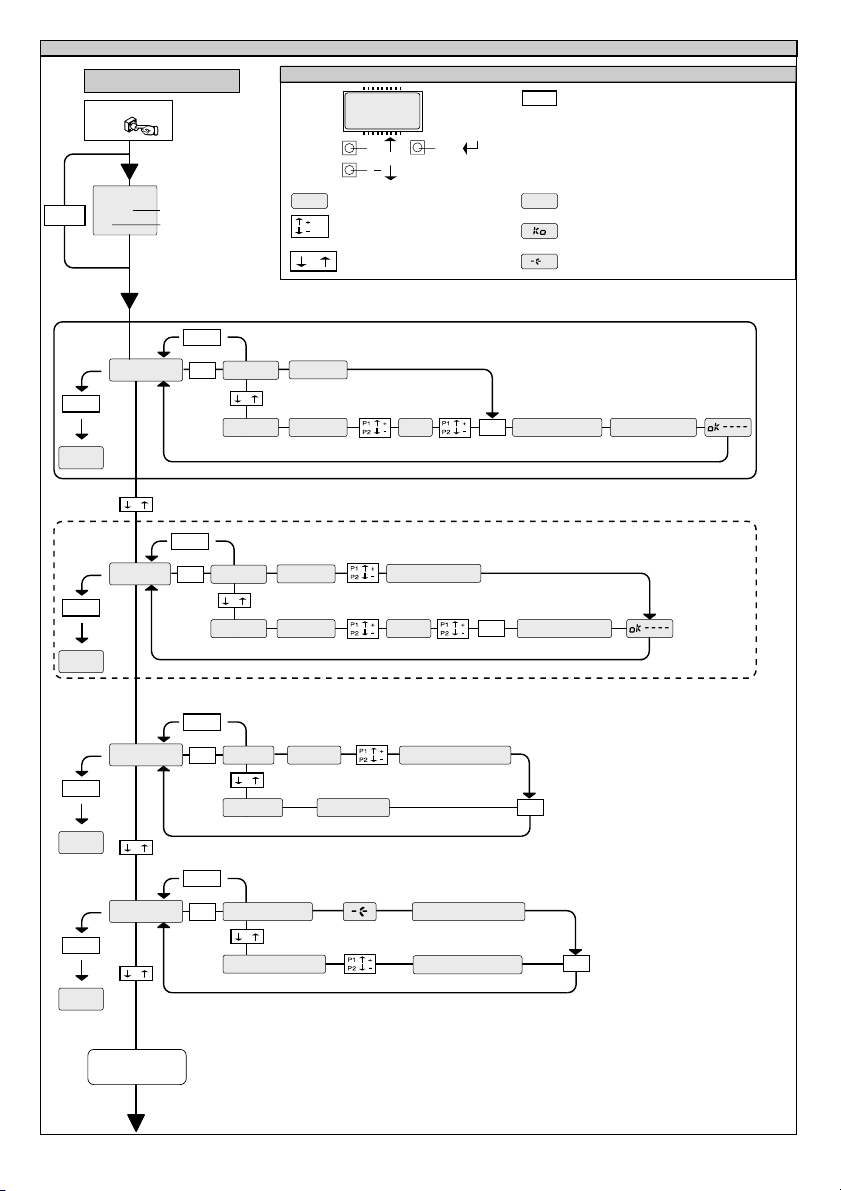
ACCESS TO MENUS
Press the OK key
OK
BFT
RTD1.0
OK
00
Software version
No. radio control devices
memorised
8888
[ 00 ]
Preset value
Parameter increment/reduction
/ON
/OFF
or ON/OFF commutation
Menu scrolling
-
+
(+ = preceding - = following)
+
Fig. A
OK
LEGENDA
Simultaneously press the + and - keys.
+/-
Simultaneous pressure of the + and – keys
allows you to exit the active menu and return
to the preceding menu; if this takes place at
the main menu level, programming is exited
and the display switched off.
The modifications made are only confirmed if
the OK key is subsequently pressed.
PRG
Message: Programming in progress
Message: KO! (value or function error)
Message: “Wait” (enter value or function)
D811373_02
+/-
END
+/-
END
+/-
END
+/-
END
ADD
-
+
add
delete
-
+
verifiy
-
+
+/-
OK
aut.
man. pos.
out1 . .4
-
+
out1 . .4
+/-
OK
aut.
man. pos.
out1 . .4
-
+
out1 . .4
+/-
OK
code
POS. r0001 . . . t618
-
+
database confirm
+/-
OK
read code
-
+
scroll archive
activate code
01 t1 . . . 2048 t4
01 t1 . . . 2048 t4
OK
hidden button
OK
attiva codice
OK
1 - RADIO RECEIVER OUT
desired button
2 -ACCESS CONTROL OUT
OK
FOLLOWING
MENUS FIG. B
16
- RTD-CA - Ver. 02
Page 17

Fig. B
D811373_02
+/-
END
PRECEDING
MENUS FIG. A
output
-
+
P1
+/-
OK OK
out1
-
+
out 2
-
+
out 3
-
+
out 4
access contr.
FIG. B1A
TRC 1-2
monos
-
+
T1 T2
P1
TRC 4
OK
T1 T2
T3
MITTO 2-4
FIG. B2A
T4
TRC 1-2
bist
-
+
timed
-
+
antipanic
-
+
access type pc conn.
-
-
+
door time
-
+
vatchdog
-
+
address
-
+
-
+
-
+
0000 . . . 2500
0000 . . . 0025
0000 . . . 0019
OK
OK
OK
+
stand-alone
-
+
free
-
+
forbidden
-
+
system reader
T1
T2
T3
T1
T2
T4
TRC 4
OK
+/-
END
confige RTD
+/-
language
-
+
password 0--- -0-- --0- ---0
ita
-
fra
-
deu
-
ENG
-
ESP
OK
+
+
+
+
OK
RTD-CA - Ver. 02 -
17
Page 18

FRANÇAIS MANUEL D’INSTALLATION
Nous vous remercions pour avoir choisi ce produit. Nous sommes certains
qu’il vous offrira les performances que vous souhaitez. Lisez attentivement
la brochure “Avertissements” et le “Manuel d’instructions” qui
accompagnent ce produit, puisqu’ils fournissent d’importantes indications
concernant la sécurité, l’installation, l’utilisation et l’entretien. Ce produit est
conforme aux règles reconnues de la technique et aux dispositions de
sécurité. Nous certifions sa conformité avec les directives européennes
suivantes: 89/336/CEE, 73/23/CEE (et modifications successives).
SECURITE GENERALE
ATTENTION! Une installation erronée ou une utilisation impropre
du produit peuvent provoquer des lésions aux personnes et aux
animaux ou des dommages aux choses.
• Lisez attentivement la brochure “Avertissements” et le “Manuel
d’instructions” qui accompagnent ce produit, puisqu’ils fournissent
d’importantes indications concernant la sécurité, l’installation,
l’utilisation et l’entretien.
• Eliminer les matériaux d’emballage (plastique, carton, polystyrène
etc.) selon les prescriptions des normes en vigueur. Ne pas laisser
des enveloppes en nylon et polystyrène à la portée des enfants.
• Conserver les instructions et les annexer à la fiche technique pour les
consulter à tout moment.
• Ce produit a été conçu et réalisé exclusivement pour l’utilisation
indiquée dans cette documentation. Des utilisations non indiquées
dans cette documentation pourraient provoquer des dommages au
produit et représenter une source de danger pour l’utilisateur.
• La Société décline toute responsabilité dérivée d’une utilisation
impropre ou différente de celle à laquelle le produit a été destiné et
qui est indiquée dans cette documentation.
• Ne pas installer le produit dans une atmosphère explosive.
• Les éléments constituant la machine doivent être conformes aux
Directives Européennes suivantes: 89/336/CEE, 1999/5/CEE et
modifications successives. Pour tous les Pays en dehors du Marché
Commun, outre aux normes nationales en vigueur il est conseillé de
respecter également les normes indiquées ci-haut afin d’assurer un
bon niveau de sécurité.
• La Société décline toute responsabilité en cas de non respect des
règles de bonne technique dans la construction des fermetures
(portes, portails etc.), ainsi qu’en cas de déformations pouvant se
produire pendant l’utilisation.
• L’installation doit être conforme aux prescriptions des Directives
Européennes: 89/336/CEE, 1999/5/CEE et modifications
successives.
• Couper l’alimentation électrique avant d’effectuer n’importe quelle
intervention sur l’installation. Débrancher aussi les éventuelles
batteries de secours, si présentes.
• Prévoir sur la ligne d’alimentation de la motorisation un interrupteur
ou un magnétothermique omnipolaire avec distance d’ouverture des
contacts égale ou supérieure à 3,5 mm.
• Vérifier qu’en amont de la ligne d’alimentation il y a un interrupteur
différentiel avec seuil de 0,03A.
• Vérifier si l’installation de terre est effectuée correctement: connecter
toutes les parties métalliques de la fermeture (portes, portails etc.) et
tous les composants de la motorisation dotés de borne de terre.
• Appliquer tous les dispositifs de sécurité (cellules photoélectriques,
barres palpeuses etc.) nécessaires à protéger la zone des dangers
d’écrasement, d’entraînement, de cisaillement.
• Appliquer au moins un dispositif de signalisation lumineuse (feu
clignotant) en position visible, fixer à la structure un panneau de
Attention.
• La Société décline toute responsabilité en matière de sécurité et de
bon fonctionnement de la motorisation si des composants d’autres
producteurs sont utilisés.
• Utiliser exclusivement des pièces originales pour n’importe quel
entretien ou réparation.
• Ne pas effectuer des modifications aux composants de la motorisation
si non expressément autorisées par la Société.
• Informer l’utilisateur de l’installation sur les systèmes de commande
appliqués et sur l’exécution de l’ouverture manuelle en cas d’urgence.
• Ne pas permettre à des personnes et à des enfants de stationner
dans la zone d’action de la motorisation.
• Ne pas laisser des radio commandes ou d’autres dispositifs de
commande à portée des enfants afin d’éviter des actionnements
involontaires de la motorisation.
• L’utilisateur doit éviter toute tentative d’intervention ou de réparation
18
- RTD-CA - Ver. 02
de la motorisation et ne doit s’adresser qu’à du personnel qualifié.
• Tout ce qui n’est pas expressément prévu dans ces instructions, est
interdit.
• L’installation doit être faite en utilisant des dispositifs de sécurité
et des commandes conformes à la norme EN 12978.
1) GENERALITÉS
Système radio récepteur à autoapprentissage, programmable, dont les
caractéristiques principales sont:
• Récepteur à 512 ou 2048 codes.
• Jusqu’à 4 sorties (1 standard + 3 modulaires) avec reconnaissance
automatique des modules insérés.
• Sorties configurables comme monostable, bistable, temporisée,
anti-agression et contrôle des accès.
• Programmation avec écran incorporé.
• Fonctions Contrôle des Accès par carte WRTD intégrée.
• Capacité de reconnaître et de mémoriser des émetteurs, des badges
sans contact, des émetteurs activés pour le contrôle des accès.
• Compatible avec le protocole EElink pour une installation et une
maintenance rapides.
• Protection du récepteur avec mot de passe.
L’intégration du système récepteur doté de clonage des émetteurs avec
le système de contrôle des accès permet une vaste typologie d’installations.
Il permet de gérer jusqu’à 4 passages d’accès en utilisant tant des radio
émetteurs (MITTO/TRC) que des transpondeurs (Compass-Isocard/
Compass-Ring/MITTO T).
Les radio émetteurs (MITTO/TRC) peuvent être gérés par le système
RTD-CA tant comme radio émetteurs traditionnels, que comme badges
sans contact.
En utilisant une interface en option COMPASS-232, le système peut être
contrôlé par le logiciel de contrôle des accès SECURBASE (en option) qui
permet un contrôle complet des accès.
Le contrôle du passage est géré par une sortie avec contact N.O.; si
nécessaire, il est possible d’augmenter le nombre de sorties avec des
modules en option permettant d’obtenir un maximum de 4 canaux de
sortie, configurables de façon indépendante.
2) CARACTÉRISTIQUES TECHNIQUES
2.1) Récepteur RTD-CA
Alimentation: ........................................................ 230V ±10%50Hz
Fréquence: ....................................................................... 433.92MHz
Température de fonctionnement: .................................... -20 / +55°C
Code par: ....................................................... Algorithme rolling-code
N° de combinaisons: ........................................................... 4 milliards
Impédance antenne: .................................................. 50Ohm (RG58)
Dimensions: .......................................................................... voir fig. 1
Contact relais: .................................................................. 0,5A - 12V=
Degré de protection: ................................................................. IP 20*
(*) Le degré de protection de l’enveloppe devient IP55 en utilisant un
accessoire pouvant être fourni en option. N’utiliser que des raccords
indiqués pour les dimensions du récipient et au diamètre du câble.
2.2) Carte WRTD
• Accès à badge sans contact/émetteurs activés
• Les paramètres de système et le tableau des codes sont mémorisés
dans une mémoire non volatile, pouvant conserver les données
introduites pendant des années même en absence d’alimentation
électrique.
• La mémoire peut gérer jusqu’à 819 badges (RTD-CA 512) ou 2500
badges (RTD-CA 2048).
• Le temps d’ouverture de la porte peut être librement programmé de
0 à 25,5 secondes.
• Le temps de contrôle de porte ouverte peut être librement programmé
de 0 à 255 secondes.
2.3) Émetteur MITTO
Touches: ....................................................................... Couleur jaune
Alimentation: ........................... 2 Piles Lithium de 3V (type CR2016)
Portée: ........................................................................ 50 / 100 mètres
Versions des émetteurs:
MITTO2 – a deux canaux, MITTO4 - à quatre canaux.
2.4) Émetteur TRC
Touches: ....................................................................... Couleur rouge
Alimentation: ........................................................... Pile Alcaline 12V
Portée ...................................................................... : 50 / 100 mètres
D811373_02
Page 19

FRANÇAISMANUEL D’INSTALLATION
Versions des émetteurs:
TRC1-monocanal, TRC2-à deux canaux, TRC4-à quatre canaux.
D811373_02
Accessoires (en option):
COMPASS-READER:
Lecteur de badges sans contact.
COMPASS-ISOCARD:
Badge sans contact standard ISO, avec possibilité de personnalisation
(photo, données, etc.)
COMPASS-RING:
Porte-clés avec transpondeur, doté des mêmes fonctions du badge.
MITTO2-T/MITTO4-T:
Émetteur rolling-code avec transpondeur, doté des mêmes fonctions du
badge.
COMPASS-232:
Convertisseur sériel pour connecter jusqu’à 19 RTD-CA à la porte sérielle
du PC.
SECURBASE:
Base de données de gestion du contrôle des accès sur PC.
Fonctions principales: données des badges, données des lecteurs,
tranches horaires, calendrier, anti-passback, auto-apprentissage des
badges.
ATTENTION: Le logiciel peut gérer un maximum de 20 sorties configurées
dans le récepteur comme contrôle des accès. Le numéro maximum de
RTD-CA pouvant être gérés dépend donc du nombre de sorties de
chaque récepteur ayant été configurées comme contrôle des accès.
MOP
Module encastré doté de sortie supplémentaire contact N.O.
3) INSTALLATION
Après avoir prédisposé le passage des câbles de connexion, fixer le
support (fig. 1), en marquant les deux trous en utilisant les deus œillets
disponibles sur le récipient comme gabarit. Selon le matériel dont le
support est constitué, utiliser directement les vis fournies en dotation ou
bien perforer avec un foret diamètre 4mm pour insérer les chevilles
fournies en dotation.
Serrer à fond les vis en rattrapant d’éventuelles erreurs de centrage en
utilisant les œillets du récipient.
ATTENTION! La carte de contrôle RTD-CA commande avec des
relais l’ouverture de la porte.
Une installation de sécurité prévoit donc le positionnement de la carte
RTD-CA à l’intérieur du bâtiment, dans une zone protégée contre
l’effraction.
Les éventuels lecteurs transpondeurs Compass-Reader peuvent être
positionnés à l’extérieur du bâtiment, étant donné qu’en cas
d’endommagement ils ne peuvent pas commander l’ouverture de la
porte.
4) SCHÉMA DE CONNEXION
Plusieurs types d’installation sont possibles, suivant le nombre de sorties
disponibles et les fonctions demandées par le système.
La Fig. 2 illustre les borniers présents dans le récepteur RTD-CA et dans
le module de contrôle des accès WRTD.
La Fig. 3 illustre le schéma de câblage d’une installation type.
La Fig. 4 illustre les connexions nécessaires entre RTD-CA, Compass232 et Compass-Reader dans des installations gérées par Securbase.
RTD-CA
JP4
1-2 Entrée alimentation 230 V ±10% 50/60Hz(1L-2N)
JP3
3 Sortie Contact Commun COM
4 Sortie Contact normalement ouvert NO
Contact pour pilotage ouverture porte.
JP2
5 - 6 Entrée antenne (5 signal - 6 gaine).
WRTD
JP6 (connexion COMPASS-READER)
1 + Alimentation
2D1
3DØ
4 0 Alimentation
5 LED A
6 LED B
Il reçoit du COMPASS-READER les données du badge présenté.
Il est possible de connecter un maximum de 2 Compass-Reader en
parallèle à chaque WRTD.
JP3
7-8 Sérielle RS 485 (7-B, 8-A)
Ils permettent la connexion sérielle de plusieurs RTD-CA dans les
systèmes interfacés avec Compass-232 à la porte sérielle COM d’un PC.
Il est conseillé de ne pas dépasser 500 m de longueur maxi de connexion.
JP5
13-12 Entrée état porte OUT1 (N.F.)
13-11 Entrée état porte OUT2 (N.F.)
13-10 Entrée état porte OUT3 (N.F.)
13-9 Entrée état porte OUT4 (N.F.)
Entrées de vérification de l’état de fermeture de la porte.
JP4
14-15-16 Alarme 14-NC, 15-NO, 16-COM
Contact d’échange pour pilotage alarme, après l’ouverture de la porte, si
celle-ci n’est pas refermée avant le “temps de contrôle porte ouverte”
introduit, a lieu la commutation entre NF et NO.
MOP (en option)
JP1
1-2 Sortie Contact normalement ouvert NO. Contact pour pilotage
ouverture porte
INSTALLATION ANTENNE
Utiliser une antenne accordée sur 433MHz.
Pour la connexion Antenne-Récepteur utiliser un câble coaxial RG58.
La présence de masses métalliques adossées à l’antenne peut
perturber la réception radio. En cas de portée insuffisante de
l’émetteur, déplacer l’antenne à un endroit plus indiqué.
5) PROGRAMMATION
Le récepteur RTD-CA unit les fonctions de radio récepteur aux fonctions
de contrôle des accès.
Si une sortie est configurée comme contrôle des accès, le menu "ajout"
est automatiquement réglé pour recevoir des badges ou des émetteurs
à activer et gérer dans la modalité de contrôle des accès.
Si l’on désire utiliser des émetteurs (MITTO/TRC) comme badges de
contrôle des accès, il faut tenir compte qu’à chaque touche (T1, T2, T3,
o T4) correspond un code badge.
Il est donc possible de réaliser une vaste typologie d’installations, où
chaque récepteur RTD-CA peut avoir des sorties configurées comme
contrôle des accès et des sorties configurées comme radio commande.
A titre d’exemple, l’installation schématisée à la Fig. 3 est configurée
comme suit:
OUT1 – Sortie radio commande standard accouplée à la touche T1
OUT2 - Sortie radio commande standard accouplée à la touche T2
OUT3 - Sortie contrôle des accès accouplée à la touche T3 de l’émetteur
qui dans ce cas a été mémorisé comme émetteur activé pour le contrôle
accès. La réception du code badge a lieu par radio.
OUT4 - Sortie contrôle des accès contrôlée par un Compass-Reader. Ce
passage est contrôlé par des badges sans contact (Compass-Isocard/
Compass-Ring) ou par le transpondeur présent dans le MITTO T.
En cas d’installations complexes, il est conseillé de réaliser au préalable
un schéma de câblage général de l’installation.
Dans ces types d’installations, le positionnement de l’antenne devra être
fait avec le plus grand soin, en tenant compte que les émetteurs peuvent
contrôler plusieurs passages, pourvu qu’ils se trouvent dans la zone de
réception de l’antenne.
NOTE: Un émetteur, pour pouvoir être activé et géré par le système
de contrôle des accès de la RTD-CA, doit forcément être un clone du
premier émetteur inséré (voir paragraphe 5.1).
Le clonage d’un émetteur n’entraîne pas l’activation automatique
des sorties configurées en modalité radio commande (sorties OUT1
et OUT2 de l’exemple). Ces émetteurs devront être insérés
manuellement dans le récepteur.
5.1) ÉMETTEURS ACTIVÉS POUR LE CONTRÔLE DES ACCÈS
Pour activer les émetteurs au fonctionnement comme contrôle des
accès, il est possible de suivre une de ces procédures:
Si dans le récepteur aucun émetteur n’a été inséré:
Insérer un premier émetteur dans une sortie au choix, à condition qu’elle
ne soit pas configurée comme contrôle des accès, de telle façon à
attribuer un code récepteur à la RTD-CA. Cloner ensuite, avec UNIRADIO,
ce premier émetteur “maître” pour obtenir tous les émetteurs à insérer par
la suite dans la gestion de contrôle des accès.
Se référer au menu “configuration”, au menu “ajout” et au paragraphe 6
“Clonage par ajout avec maître”.
RTD-CA - Ver. 02 -
19
Page 20

FRANÇAIS MANUEL D’INSTALLATION
NOTE IMPORTANTE: MARQUER LE PREMIER ÉMETTEUR
MÉMORISÉ AVEC L’ÉTIQUETTE CLÉ (MAITRE).
Si un émetteur clé a déjà été inséré dans le récepteur, mais il n’est
pas disponible:
Lire avec UNIRADIO le code inséré dans le récepteur (voir paragraphe
6 “Lecture du code”), puis obtenir, comme indiqué dans le paragraphe
“Clonage par ajout avec code”, tous les émetteurs à insérer par la suite
dans la gestion de contrôle des accès.
Le numéro de code attribué permettra à tout moment de créer et de
cloner d’autres émetteurs activés. Il est donc conseillé de le marquer
sur la carte spéciale fournie et de la remettre à l’usager (Fig. 7).
Se référer aux instructions UNIRADIO pour d’autres informations.
5.2) DESCRIPTION DES MENUS DE PROGRAMMATION:
Ajouter:
Permet d’ajouter un émetteur, un badge ou un émetteur activé au contrôle
des accès dans la mémoire du récepteur.
Deux modalités sont possibles:
Auto: l’émetteur ou le badge sont insérés dans le premier
emplacement de mémoire libre disponible.
Manuel: le numéro de l’emplacement de mémoire dans lequel
l’émetteur ou le badge doivent être insérés est demandé. Cette
modalité est utile si l’on désire attribuer un numéro progressif
aux différents émetteurs/badges, de façon à faciliter une
élimination successive éventuelle de la mémoire du récepteur.
Après avoir sélectionné la modalité automatique ou manuelle, il faut:
1) Sélectionner, avec les touches + et -, la sortie que l’on désire activer.
2) Si la sortie est configuré comme monostable, bistable, temporisée ou
anti-agression (menu ajout 1 Fig. A):
Appuyer sur la touche cachée P1 de l’émetteur, puis appuyer sur la
touche (T1, T2, T3 ou T4) de l’émetteur que l’on désire accoupler à
la sortie précédemment sélectionnée.
3) Si la sortie est configuré comme contrôle des accès (menu ajout 2
Fig. A):
Présenter au Compass-Rader un badge à activer ou appuyer sur une
touche (T1, T2, T3 ou T4) d’un émetteur activé (voir paragraphe
“ÉMETTEURS ACTIVÉS POUR LE CONTRÔLE DES ACCÈS”).
Note: La touche cachée P1 prend un aspect différent suivant le modèle
d’émetteur.
Pour TRC 1-2 / MITTO 2-4, appuyer sur la touche cachée P1 (Fig. B1A).
Pour TRC 4 , la touche P1 correspond à l ’appui simultané sur les 4 touches
de l’émetteur ou, en ouvrant le compartiment de la batterie, au pontet
réalisé avec un tournevis entre les deux plaquettes P1 (Fig. B1A).
Effacer:
Permet d’effacer de la mémoire du récepteur un ou tous les émetteurs/
badges introduits.
Codes: permet d’éliminer un émetteur/badge de la mémoire du
récepteur en introduisant le numéro de position dans la mémoire
(voir menu ajout-manuel).
Archives: permet d’éliminer TOUS les émetteurs et
transpondeurs de la mémoire du récepteur. Une confirmation de
l’opération est demandée, afin d’éviter des effacements
involontaires.
Note: dans ce menu, les émetteurs sont indiqués par la lettre “R” (ex.
R002), les badges et les radio commandes activés sont indiqués par la
lettre “T” (ex. T012).
Vérification:
Permet de vérifier la présence dans la mémoire d’un émetteur/badge ou
d’en afficher la liste complète.
Lire codes: il faut appuyer sur une touche de l’émetteur ou
présenter le badge ou la radio commande activée. Si mémorisé,
il affiche le numéro d’emplacement et le numéro de la touche en
cas d’émetteurs, ou le numéro d’emplacement, suivi par le
message "transp", en cas de badges/émetteurs activés.
Consulter liste: en utilisant les touches + et -, il est possible de
faire défiler la liste de toutes les émetteurs/badges mémorisés,
l’appui prolongé sur la touche accélère le défilement de la liste.
Sortie:
Permet de configurer le comportement des sorties présentes dans le
récepteur.
Configuration sortie 1, 2, 3, 4: sélectionner la sortie que l’on
désire configurer, en utilisant les touches + et -.
20
- RTD-CA - Ver. 02
Chaque sortie peut être configurée selon ces modalités:
1) impulsive (monostable) le relais de la sortie accouplée
reste attirée tant que la touche correspondante de l’émetteur
reste enfoncée.
2) pas-à-pas (bistable) le relais de la sortie accouplée change
d’état à chaque appui sur la touche de l’émetteur.
3) temporisée à chaque appui sur la touche de l’émetteur, le
relais de la sortie reste attiré pendant 90 secondes. Des appuis
sur la touche pendant le cycle de comptage remettent à zéro le
comptage.
4) anti-agression le relais de la sortie accouplée change
d’état si l’appui sur la touche de l’émetteur dure plus de 5
secondes. Toutes les touches de tous les émetteurs insérés
dans le récepteur sont automatiquement dotées de la fonction
anti-agression, indépendamment de leur configuration, donc
l’attribution d’une touche (T1, T2, T3 ou T4) à la sortie n’est pas
nécessaire.La commutation du relais a une durée de 10s.
5) contrôle des accès le relais de la sortie accouplée ne
change d’état qu’à la suite de la présentation d’un badge activé
ou de la réception d’un code émetteur activé.
Le réglage d’une sortie en modalité contrôle des accès exige la
configuration successive des paramètres suivants:
Type d’accès:
avec PC (brnch. PC): la sortie est configurée pour être gérée
par le logiciel de contrôle des accès Securbase (Fig. 4-5). La
reconnaissance et l’activation d’un badge ou d’un émetteur
activé sont effectuées à distance.
stand alone: la sortie est configurée pour être gérée sans logiciel
Securbase. La reconnaissance et l’activation d’un badge ou d’un
émetteur activé sont effectuées par le récepteur RTD-CA.
libre: la sortie change d’état à la réception d’un code badge
quelconque (activé ou non activé)
enterdit: la sortie est bloquée (porte toujours fermée)
lecteur de système: à utiliser en cas de présence du logiciel
Securbase. S’il est configuré comme lecteur de système, le
récepteur est prédisposé pour l’introduction séquentielle de
badges et d’émetteurs activés. Pour des raisons pratiques, il est
conseillé de régler comme lecteur de système un récepteur
RTD-CA doté d’un lecteur Compass-Reader positionné à
proximité du PC.
Pour l’introduction séquentielle d’émetteurs activés, il faut
configurer une RTD-CA comme lecteur de système
Temps relais porte:
incrémenter ou décrémenter avec les touches +/- la valeur du
temps d’attraction du relais porte à la suite de la réception d’un
badge ou d’un émetteur valable. La valeur est exprimée en
dixièmes de seconde, variable de 0 à 25,5 s. Si la valeur est
introduire à 0, le relais reste attiré jusqu’à ce que la porte n’est
refermée.
Temps de contrôle de la porte:
incrémenter ou décrémenter avec les touches +/- la valeur du
temps de contrôle de la porte. La valeur est exprimée en
secondes, variable de 0 à 255 s. Si dans ce temps le contact de
contrôle de l’état porte correspondant à la sortie n’est pas fermé,
a lieu la commutation du relais d’alarme qui continue jusqu’à la
fermeture du contact. Si le temps de contrôle de la porte n’est
pas réglé à 0, la fonction est désactivée.
Adresse:
avec les touches +/-, composer l’adresse de communication
(polling) sur la ligne sérielle 485. À utiliser en cas de plusieurs
sorties de contrôle des accès connectées à la ligne sérielle.
Claque sortie configurée comme contrôle des accès devra avoir
une adresse univoque compris entre 0 et 19. La présence de
deux sorties avec la même adresse provoque des problèmes au
niveau du logiciel. L’adresse de défaut est 1 pour la sortie 1, 2
pour la sortie 2, 3 pour la sortie 3, 4 pour la sortie 4. L’adresse
n’a aucune incidence en cas de systèmes stand-alone.
Notes:
1) Les sorties de défaut sont configurées comme monostables. Sune
seule sortie peut être configurée en modalité anti-agression.
2) S’il fallait vérifier la modalité où une sortie à été configurée, il faut la
sélectionner et appuyer sur la touche OK. Le récepteur affiche
comme première option la modalité de fonctionnement précédemment
réglée.
D811373_02
Page 21

FRANÇAISMANUEL D’INSTALLATION
3) Si l’on cherche à configurer une sortie n’étant pas dotée de module
en option MOP, le système affichera le message d’erreur “module
D811373_02
non présent”.
4) En cas d’anomalies de fonctionnement du PC ou en tous les cas
d’absence de communication entre Securbase et RTD-CA, les
fonctions stand-alone du récepteur RTD-CA restent actives et le
récepteur peut toujours vérifier les badges enregistrés dans sa
mémoire. Il est donc conseillé de copier les badges utilisés plus
souvent ou les badges plus importants de la base de données de
Securbase à la mémoire de la RTD-CA. Se référer aux instructions
Securbase pour d’autres renseignements.
5) Le tableau suivant fournit la capacité de mémoire des versions:
RTD-CA N° maxi de badges ou N° maxi Total
512 819 512 819
2048 2500 2048 3270
Chaque mémorisation occupe un emplacement de mémoire
indépendamment du type de dispositif inséré, donc si, par exemple, 400
émetteurs sont mémorisés dans une RTD-CA 512, 419 emplacements
resteront disponibles pour mémoriser des badges (819-400=419).
Configuration RTD-CA:
Permet d’introduire les fonctions générales du système.
6) CLONAGE DES RADIO ÉMETTEURS
CLONAGE PAR AJOUT AVEC MAITRE
Pour la réalisation pratique des clones avec l’émetteur maître (marqué de
l’étiquette clé), se référer aux instructions du dispositif UNIRADIO ou
suivre la procédure simplifiée suivante:
1) Allumer UNIRADIO et attendre le message de bienvenue.
2) Avec les touches <flèche en haut> et <flèche en bas> s électionner
la rubrique <aller au menu numéro>.
3) Appuyer sur <retour>.
4) Au menu suivant, composer le numéro 2122 et appuyer sur <retour>.
5) Suivre les instructions affichées sur l’écran de UNIRADIO.
LECTURE DU CODE
Si l’on ignore le code d’un récepteur, il faut effectuer la lecture en
procédant comme suit.
1) Allumer UNIRADIO et attendre le message de bienvenue.
2) Avec les touches <flèche en haut> et <flèche en bas> s électionner
la rubrique <aller au menu numéro>.
3) Appuyer sur <retour>.
4) Au menu suivant, composer le numéro 225 et appuyer sur <retour>.
5) Suivre les instructions affichées sur l’écran de UNIRADIO.
CLONAGE PAR AJOUT AVEC CODE
Après avoir effectué la lecture du code clé, il est conseillé de le
marquer sur la carte spéciale fournie et de le remettre à l ’usager (Fig.
7).
Pour la réalisation pratique des clones, se référer aux instructions du
dispositif UNIRADIO ou bien, pour les clones en ajout, suivre la procédure
simplifiée suivante:
1) Allumer UNIRADIO et attendre le message de bienvenue.
2) Avec les touches <flèche en haut> et <flèche en bas> s électionner
la rubrique <aller au menu numéro>.
3) Appuyer sur <retour>.
4) Au menu suivant, composer le numéro 2121 et appuyer sur <retour>.
5) Suivre les instructions affichées sur l’écran de UNIRADIO.
Au moyen du dispositif UNIRADIO (Fig. 6), il est possible, en outre, de
lire et copier les listes des émetteurs mémorisés d’une RTD-CA à une
autre.
Par contre, avec UNIRADIO il n’est pas possible de modifier les listes.
UNIPRO ne supporte pas la configuration des sorties de la RTD-CA.
Le récepteur alimente le programmeur UNIPRO, qui nécessite donc un
alimentateur spécial ou de batteries chargées.
d’émetteurs activésd’émetteurs
Langue: sélectionner la langue voulue parmi celles disponibles
(Italien, français, allemand, anglais, espagnol).
PAssword: avec les touches +/-, il est possible d’introduire un
mot de passe constitué de 4 chiffres (0 à 9). Si l’on compose une
valeur différente de celle de défaut (0000), le système demandera
le mot de passe d’accès lors de la tentative de configuration
suivante. Si l’on ne désire pas protéger la programmation du
récepteur par un mot de passe, il faut réintroduire la valeur de
défaut 0000.
7) CONNEXION AU PC
Le système RTD-CA peut être interfacé avec un ordinateur individuel
pour le monitorage des accès (Fig. 4-5).
Dans ce cas, les accessoires suivants sont nécessaires:
COMPASS-232 Interface PC: permet la connexion sérielle entre RTDCA et PC. Le numéro maxi de sorties pouvant être gérées est 20.
NOTE: Connecter à la RTD-CA la plus éloignée sur la ligne une résistance
de 120 Ohm/0,25W entre les bornes 7 et 8, comme indiqué à la Fig. 5.
SECURBASE Logiciel de monitorage, dont les fonctions principales
sont:
• Incrémenter le nombre maxi de badges mémorisables et gérables
(seule limite la mémoire du PC).
• Utilisation de tranches horaires d’activation des accès (l’usager peut
accéder exclusivement dans une certaine tranche horaire).
• Utilisation du calendrier d’activation des accès (l’usager peut accéder
exclusivement les jours fixés).
• Anti-passback, en installant un groupe supplémentaire RTD-CA/
Compass-Reader à la sortie, l’on vérifie la sortie d’un badge.
• Affichage en temps réel des accès.
• Affichage en temps réel des données personnelles du titulaire du
badge.
• Possibilité d’introduction des paramètres des lecteurs reliés.
• Enregistrement des accès avec possibilité de recherches et
d’impressions.
La gestion des badges en Securbase se fait à travers un lecteur de
système représenté par un groupe quelconque RTD-CA/CompassReader.
Voir menu configuration-contrôle des accès-lecteur de système.
COMPASS READER
Le lecteur de badges sans contact Compass-Reader est doté d’une led
dont la couleur change selon l’état de la sortie:
Vert: libre accès ou contact d’ouverture attiré.
Rouge: accès interdit
Jaune: fonctionnement normal (attente du code)
Jaune clignotant: attente interrogation Securbase
Jaune/Vert clignotant: Lecteur de système
Si plusieurs sorties sont configurées comme contrôle des accès, la led ne
répondra qu’à l’état de la sortie 4.
Il est en tous les cas possible de contrôler plusieurs sorties de la RTD-CA
avec un seul lecteur Compass-Reader.
Cette fonction est particulièrement utile en cas d’accès rapprochés, dans
lesquels il sera possible d’activer des groupes séparés de badges à
chaque sortie RTD-CA.
8) ENTRETIEN
L’entretien de l’installation doit être effectué régulièrement de la
part de personnel qualifié. Les émetteurs sont alimentés par 2 batteries
au lithium de 3V (type CR2016). Les émetteurs TRC sont alimentés par
une pile alcaline 12V.Pendant le remplacement des batteries de type
CR2016, il faut éviter le contact des pôles avec les mains.
Une réduction de la portée de l’émetteur peut être due aux batteries en
train de se décharger. Quand la led de l’émetteur clignote, cela indique
que les batteries sont à plat et qu’il faut les remplacer.
9) DÉMOLITION
ATTENTION: s’adresser uniquement à du personnel qualifié.
L’élimination des matériaux doit être faite en respectant les normes en
vigueur. En cas de démolition du système, il n’existe aucun danger ou
risque particulier dérivant de ses composants. En cas de récupération
des matériaux, il sera opportun de les trier selon leur genre (parties
électriques - cuivre - aluminium - plastique - etc.). Pour l’élimination de la
batterie, se référer aux normes en vigueur.
Les descriptions et les figures de ce manuel n’engagent pas le
constructeur. En laissant inaltérées les caractéristiques essentielles
du produit, la Société se réserve le droit d’apporter à n’importe quel
moment les modifications qu’elle juge opportunes pour améliorer le
produit du point de vue technique, commercial et de construction,
sans s’engager à mettre à jour cette publication.
RTD-CA - Ver. 02 -
21
Page 22

ACCES AUX MENUS
Appuyer sur la
touche OK
OK
BFT
RTD1.0
OK
00
Version logiciel
N° commandes radio
mémorisées
8888
+
[ 00 ]
Valeur prédéfinie
Incrément/réduction paramètres ou
/ON
/OFF
commutation ON/OFF
Défilement du menu
-
+
(+ = précédent - = suivant)
Fig. A
OK
LEGENDA
Appuyer simultanément sur les touches + et -.
+/-
L’ appui simultané sur les touches + et –
permet de sortir du menu et de retourner au
menu préc édent; si cela a lieu au niveau
principal du menu, on sort de la
programmation et l’écran s’éteint.
Les modifications effectuées ne sont validées
que si elles sont suivies par l’appui de OK.
Message Programmation en cours
PRG
Message KO! (erreur de la valeur ou de la
fonction)
Message "Attendez s.v.p." (introduire la valeur
ou la fonction)
D811373_02
+/-
FIN
+/-
FIN
+/-
FIn
+/-
FIN
+/-
adjouter
-
+
OK
+/-
adjouter
OK
+/-
effacer
-
+
OK
+/-
verificaton
-
+
OK
sortie1 . .4
aut.
-
+
man. pos.
sortie1 . .4
sortie1 . .4
aut.
-
+
man. pos.
sortie1 . .4
codes
POS. r0001 . . . t618
-
+
activa. code
Archives Confirmer
lire codes
-
+
consulter liste
OK
OK
OK
01 t1 . . . 2048 t4
01 t1 . . . 2048 t4
1 -SORTIE RADIOCOMMANDE
touche cachee
touche desirre
2 -SORTIE CONTRÔLE DES ACCÈS
activa. code
OK
MENUS SUIVANTS
22
- RTD-CA - Ver. 02
FIG. B
Page 23

Fig. B
D811373_02
+/-
FIN
MENUS
PRECEDENTS
FIG. A
sortie
-
+
P1
+/-
OK OK
sortie1
-
+
sortie 2
-
+
sortie 3
-
+
sortie 4
contr. acc.
FIG. B1A
TRC 1-2
monos.
-
+
T1 T2
P1
TRC 4
OK
T1 T2
T3
MITTO 2-4
FIG. B2A
T4
TRC 1-2
bista.
-
+
tempo.
-
+
antiagr.
-
+
type acc. brnc. PC
-
-
+
t. porte
-
+
t. cont. porte
-
+
Adresse
-
+
-
+
-
+
0000 . . . 2500
0000 . . . 0025
0000 . . . 0019
OK
OK
OK
+
stand-alone
-
+
libre
-
+
enterdit
-
+
lectur de sys
T1
T2
T3
T1
T2
T4
TRC 4
OK
+/-
FIN
configuration RTD
+/-
langue
-
+
password 0--- -0-- --0- ---0
ita
OK
-
+
fra
-
+
deu
-
+
ENG
-
+
ESP
OK
RTD-CA - Ver. 02 -
23
Page 24

DEUTSCH
MONTAGEANLEITUNG
Wir danken Ihnen, daß Sie sich für diese Anlage entschieden haben. Ganz
sicher wird sie mit ihren Leistungen Ihren Ansprüchen vollauf gerecht
werden. Lesen Sie aufmerksam die Broschüre “Hinweisen“ und die
“Gebrauchsanweisung“ durch, die dem Produkt beiliegen. Sie enthalten
wichtige Hinweise zur Sicherheit, Installation, Bedienung und Wartung der
Anlage. Dieses Produkt genügt den anerkannten technischen Regeln und
Sicherheitsbestimmungen. Wir bestätigen, daß es mit folgenden
Europäischen Richtlinien übereinstimmt: 89/336/EWG, 73/23/EWG (und
ihren nachfolgende Änderungen).
ALLGEMEINE SICHERHEITSHINWEISE
ACHTUNG! Die falsche Installation oder der unsachgemäße Gebrauch
der Anlage kann Personen-oder Sachschäden nach sich ziehen.
• Lesen Sie aufmerksam die Broschüre mit den “Hinweisen” und die
“Gebrauchsanweisung”, die dem Produkt beiliegen. Sie enthalten
wichtige Hinweise zur Sicherheit, Montage, Bedienung und Wartung
der Anlage.
• Verpackungsmaterialien (Plastik, Karton, Polystyrol u. a.) sind nach
den einschlägigen Vorschriften zu entsorgen. Keine Plastik-oder
Polystyroltüten in Reichweite von Kindern liegenlassen.
• Die Anleitung ist für zukünftige Einsichtnahme als Beilage zur
technischen Akte aufzubewahren.
• Dieses Produkt wurde ausschließlich für den Gebrauch entwickelt und
gebaut, wie er in dieser Dokumentation beschrieben wird.
Davon abweichende Verwendungen können Schadens und
Gefahrenquellen darstellen.
• Der Hersteller lehnt jede Verantwortung für Folgen ab, die durch den
unsachgemäßen oder nicht bestimmungsgemäßen, weil in dieser
Dokumentation nicht genannten Gebrauch entstehen.
• Die Anlage darf nicht in explosionsgefährdeter Atmosphäre installiert werden.
• Die Bauteile der Maschine müssen den folgenden Europäischen
Richtlinie 89/336/EWG , 1999/5/EWG, und nachfolgenden Änderungen.
Für alle Länder außerhalb der EWG gilt: Außer den geltenden
Landesvorschriften sollten aus Sicherheitsgründen auch die oben
genannten Bestimmungen beachtet werden.
• Der Hersteller lehnt jede Verantwortung für Folgen ab, die durch nicht
fachgerechte Ausführung von Schließvorrichtungen (Türen, Tore usw.),
oder durch Verformungen während des Betriebes entstehen.
• Die Montage muß im Einklang mit folgenden Europäischen Richtlinie
89/336/EWG , 1999/5/EWG, und nachfolgenden Änderungen.
• Vor jedem Eingriff an der Anlage die Stromversorgung unterbrechen.
Auch vorhandene Pufferbatterien sind abzuklemmen.
• Versehen Sie die Versorgungsleitung der Anlage mit einem Schalter
oder allpoligen magnetthermischen Schutzschalter mit einem
Kontaktabstand von mindestens
• Der Versorgungsleitung muß ein Fehlerstromschutzschalter mit einer
Schwelle von 0.03A vorgeschaltet sein.
• Prüfen Sie. ob der Erdungsanschluß richtig vorgenommen wurde: Alle
Metallteile der Schließanlage (Türen, Tore etc.) und alle Anlagenkomponenten
müssen mit einer Erdungsklemme verbunden sein.
• Bringen Sie alle Sicherheitsvorrichtungen an (Fotozellen,
Sicherheitsleisten etc.), die im Bereich zum Schutz vor Quetschungen,
Mitschleifen und Schnittverletzungen erforderlich sind.
• Bringen Sie in gut sichtbarer Position mindestens eine
Leuchtsignaleinrichtung (Blinklampe) an und befestigen Sie am
Torgestell ein Warnschild.
• Der Hersteller lehnt jede Verantwortung für die Sicherheit und die
Funktionstüchtigkeit der Anlage ab, wenn Komponenten anderer
Produzenten verwendet werden.
• Für Wartungen und Reparaturen ausschließlich Originalteile verwenden.
• Keine Umbauten an Anlagenkomponenten vornehmen, wenn sie nicht
ausdrücklich vom Hersteller genehmigt wurden.
• Weisen Sie den Anlagenbetreiber in die vorhandenen
Steuerungssysteme und die manuelle Toröffnung im Notfall ein.
• Kindern oder Erwachsenen darf nicht gestattet werden, im
Aktionsbereich der Anlage zu verweilen.
• Keine Fernbedienungen oder andere Steuerungsvorrichtungen in
Reichweite von Kindern liegenlassen. Sie könnten die Anlage
versehentlich in Gang setzen.
• Der Betreiber hat jeden Versuch eines Eingriffes oder der Reparatur zu
unterlassen. Nur entsprechend qualifizierte Fachleute sind hierzu befugt.
• Alles, was nicht ausdrücklich in dieser Anleitung genannt ist, ist
untersagt.Die Installation muß mit Sicherheits- und
Steuerungsvorrichtungen vorgenommen werden, die der Norm EN
12978 entsprechen.
24
- RTD-CA - Ver. 02
3,5 mm.
1) ÜBERSICHT
Funkempfangsanlage mit Selbstlerntechnik, programmierbar, mit folgenden
Hauptmerkmalen:
• Empfänger mit 512 oder 2048 Codes
•
Bis zu 4 ausgänge (1 standard + 3 modular) mit automatischen
Erkennung der einbezogenen Module.
• Ausgänge konfigurierbar als monostabil, bistabil, zeitgeschaltet, für
Aggressionssicherung und Zugangskontrolle.
• Programmierung am eingebauten Display.
• Betrieb mit festem und variablem Code.
• Zugangskontrollfunktionen mittels integrierter Karte WRTD
• Möglichkeit zur Erkennung und Speicherung von Sendern, kontaktlosen
Ausweiskarten und Sendern, die für die Zugangskontrolle aktiviert
sind.
• Kompatibel mit dem Protokoll EElink für eine schnelle Installation und
Wartung.
• Paßwortschutz des Empfängers.
Das Empfängersystem mit Senderklonierung gestattet in Kombination mit
dem Zugangskontrollsystem eine Vielzahl von Anlagenausführungen.
Es lassen sich bis zu 4 Zugänge sowohl mit Funksendern (MITTO/TRC) als
auch mit Transponder (Compass-Isocard/Compass-Ring/MITTO T)
kontrollieren. Die Funksender (MITTO/TRC) können vom System RTD-CA
als herkömmliche Funksender oder als kontaktlose Ausweiskarten behandelt
werden.
Benutzt man die Zusatzschnittstelle COMPASS-232, kann das System von
der Software SECURBASE (Optional) überwacht werden, welche die
lückenlose Kontrolle aller Zugänge ermöglicht.
Die Kontrolle der Durchgangsöffnung wird von einem Schließer (N. O.)
gesteuert. Bedarfsweise kann die Anlage durch Zusatzmodule auf bis zu
vier unabhängig voneinander konfigurierbare Ausgangskanäle aufgerüstet
werden.
2) TECHNISCHE DATEN
2.1) Empfänger RTD-CA
Netzversorgung: ................................................... 230V ± 10%50Hz
Frequenz: ......................................................................... 433.92MHz
Betriebstemperatur: ......................................................... -20 / +55°C
Art der Verschlüsselung: ................................. Rollcode-Algorithmus
Kombinationen: ................................................................ 4 Milliarden
Antennenimpedanz: ................................................... 50Ohm (RG58)
Abmessungen: ................................................................. siehe Fig. 1
Relaiskontakt: ................................................................... 0,5A - 12V=
Schutzgrad: ............................................................................... IP 20*
(*) Der Schutzgrad der Umhüllung erhöht sich auf IP55, wenn man ein auf
Anfrage erhältliches Zubehörteil benutzt. Benutzen Sie nur
Verbindungsstücke, die zu den Abmessungen des Behälters und zum
Kabeldurchmesser passen.
2.2) Karte WRTD
• Zugang mit kontaktloser Karte / aktivierten Sendern
• Die Systemparameter und die Codetabelle sind in einem
Permanentspeicher ablegbar, der die Daten auch ohne
Stromversorgung jahrelang bewahrt.
• Der Speicher kann bis zu 819 Ausweiskarten (RTD-CA 512) oder 2500
Ausweiskarten (RTD-CA 2048) aufnehmen.
• Die Türöffnungsdauer kann zwischen 0 und 25,5 Sekunden beliebig
vorgegeben werden.
• Die Dauer für die Türöffnungskontrolle kann zwischen 0 und 255
Sekunden beliebig vorgegeben werden.
2.3) Sender MITTO
Tasten: .......................................................................................... Gelb
Stromversorgung...................... : 2 Litiumbatterien 3V (Typ CR2016)
Reichweite: .................................................................. 50 - 100 Meter
Senderversionen:
MITTO2 - Zweikanal, MITTO4 - Vierkanal.
2.4) Sender TRC
Tasten: ............................................................................................ Rot
Stromversorgung: .................................................. Alkalibatterie 12V
Reichweite: .................................................................. 50 - 100 Meter
Senderversionen:
TRC1-Einkanal, TRC2-Zweikanal, TRC4-Vierkanal.
Zubehör (Extras):
COMPASS-READER:
Lesegerät mit Näherungssensor für kontaktlose Ausweiskarten.
D811373_02
Page 25

MONTAGEANLEITUNG
DEUTSCH
COMPASS-ISOCARD:
Kontaktlose Ausweiskarte ISO-Standard mit Personalisierung-
D811373_02
smöglichkeiten (Foto, Personalien, etc.)
COMPASS-RING:
Schlüsselanhänger mit Transponder, der die gleichen Funktionen wie die
Ausweiskarte hat.
MITTO2-T/MITTO4-T:
Rollcodesender mit Transponder, der die gleichen Funktionen wie die
Ausweiskarte hat.
COMPASS-232:
Serieller Konverter für den Anschluß von bis zu 19 Einheiten RTD-CA an
den seriellen PC-Port.
SECURBASE:
Datenbank für die Verwaltung der Zugangskontrolle auf PC.
Hauptfunktionen: Datenarchiv Ausweiskarten, Datenarchiv Lesegeräte,
Zeitnischen, Kalender, Antipassback, Selbstregistrierung Ausweiskarten.
ACHTUNG: Die Software verwaltet maximal 20 Ausgänge, die im Empfänger
für die Zugangskontrolle konfiguriert sind. Wieviele Einheiten RTD-CA
anschließbar sind, hängt somit von der Anzahl der Ausgänge ab, die in
jedem Empfänger für die Zugangskontrolle konfiguriert wurden.
MOP
Einsteckmodul mit Schließer (N.O.) als Zusatzausgang.
3) INSTALLATION
Nach der Verlegung der Anschlußkabel wird die Halterung befestigt (Fig. 1):
Die beiden Bohrungen werden vorher angezeichnet, die beiden Langlöcher
im Behälter als Schablone benutzend. Je nach Material, aus dem der
Untergrund besteht, werden entweder direkt die mitgelieferten Schrauben
benutzt oder alternativ mit einem 4 mm durchmessenden Bohrer ein Loch
gebohrt, in das die beiliegenden Dübel eingeführt werden.
Die Schrauben werden vollständig angezogen, Zentrierfehler sind mit Hilfe
der Langlöcher im Behälter ausgleichbar.
ACHTUNG! Die Steuerkarte RTD-CA veranlaßt die Türöffnung mittels
Relais.
Eine Sicherheitsanlage erfordert somit die Unterbringung der Karte RTDCA innerhalb des Gebäudes an einem bruchsicheren Ort.
Leseeinheiten für Transponder Compass-Reader können außerhalb des
Geäudes positioniert werden, weil auch bei gewaltsamer Manipulation
keine Türöffnung veranlaßt werden kann.
4) ANSCHLUSSPLAN
Je nach Anzahl der verfügbaren Ausgänge und erforderlichen
Systemeigenschaften sind mehrere Arten der Installation möglich.
In Fig. 2 sind die Klemmenblöcke dargestellt, die im Empfänger RTD-CA
und im Zugangskontrollmodul WRTD vorhanden sind.
Fig. 3 zeigt den Verdrahtungsplan einer Standardanlage.
Fig. 4 zeigt die notwendigen Verbindungen zwischen RTD-CA, Compass232 und Compass-Reader in Anlagen, die mit Securbase verwaltet werden.
RTD-CA
JP1
1-2 Ausgang Schließer NO. Steuerkontakt für Türöffnung
JP4
1-2 Eingang Netzversorgung 230 V ±10% 50/60Hz(1L-2N)
JP3
3 Ausgang Kontakt Common COM
4 Ausgang Schließer NO
Steuerkontakt für die Türöffnung.
JP2
5 - 6 Antenneneingang (5 Signal - 6 Geflecht).
WRTD
JP6 (Anschluß COMPASS-READER)
1 + Netzversorgung
2D1
3DØ
4 0 Netzversorgung
5 LED A
6 LED B
Empfängt von COMPASS-READER die Daten der eingelesenen
Ausweiskarte.
An jede Einheit WRTD lassen sich maximal 2 Compass-Reader parallel
anschließen.
JP3
7-8 Seriell RS 485 (7-B, 8-A)
Für den seriellen Anschluß mehrerer mittels Compass-232 vernetzter
Einheiten RTD-CA an den seriellen Port COM eines PC. Es wird empfohlen,
die maximale Anschlußdistanz von 500 m nicht zu überschreiten.
JP5
13-12 Eingang Türstatus OUT1 (N.C.)
13-11 Eingang Türstatus OUT2 (N.C.)
13-10 Eingang Türstatus OUT3 (N.C.)
13-9 Eingang Türstatus OUT4 (N.C.)
Prüfeingänge für den Schließzustand der Tür.
JP4
14-15-16 Alarm 14-NC, 15-NO, 16-COM
Wechselkontakt für Alarmauslösung nach Öffnung der Tür: Wenn diese
nicht innerhalb einer eingestellten "Prüfdauer Türöffnung" wieder
geschlossen wird, erfolgt die Umschaltung zwischen NC und NO.
MOP (optional)
JP1
1-2 Ausgang Schließer NO. Steuerkontakt für Türöffnung.
ANTENNENINSTALLATION
Verwenden Sie eine auf die Frequenz von 433MHz abgestimmte Antenne.
Die Verbindung Antenne-Empfänger wird mit einem Koaxialkabel RG58
hergestellt.
Metallische Massen in Antennennähe können den Funkempfang stören.
Falls die Reichweite des Senders nicht ausreicht, versetzen Sie die
Antenne an eine Stelle mit besserem Empfang.
5) PROGRAMMIERUNG
Der Empfänger RTD-CA vereinigt die Funktionen als Funkempfänger und
Zugangskontrolleinrichtung.
Ist ein Ausgang für die Zugangskontrolle eingerichtet, wird das Menü
"Hinzufügen" automatisch so eingestellt, daß es Ausweiskarten oder Sender
aufnimmt, die im Modus Zugangskontrolle aktiviert und verwaltet werden
müssen.
Sollen Sender (MITTO/TRC) als Ausweiskarten für die Zugangskontrolle
verwendet werden, ist zu beachten, daß jeder Taste (T1, T2, T3, oder T4)
ein Ausweiscode entspricht.
Auf diese Weise ist eine Vielzahl von Anlagenausführungen möglich, wobei
jeder Empfänger RTD-CA gleichzeitig Ausgänge besitzen kann, die für die
Zugangskontrolle und für die Fernsteuerung eingerichtet sind.
Beispielhaft ist in Fig. 3 eine folgendermaßen konfigurierte Anlage dargestellt:
OUT1 - Ausgang mit Taste T1 verbundene Standard-Fernsteuerung
OUT2 - Ausgang mit Taste T2 verbundene Standard-Fernsteuerung
OUT3 - Zugangskontrollausgang, der Taste T3 des Senders zugewiesen,
der in diesem Fall als für die Zugangskontrolle aktivierter Sender gespeichert
wurde. Der Ausweiskartencode wird über Funk empfangen.
OUT4 - Zugangskontrollausgang, gesteuert von einem Compass-Reader.
Diese Durchgangsöffnung wird durch kontaktlose Ausweiskarten (CompassIsocard/Compass-Ring) oder durch den Transponder des Senders MITTO
T gesteuert.
Bei komplexen Anlagen wird empfohlen, vorab einen umfassenden
Verdrahtungsplan für die Anlage zu erstellen.
Bei diesen Anlagentypen bekommt die Platzierung der Antenne besonderes
Gewicht. Dabei ist zu berücksichtigen, daß die Sender mehr als einen
Durchgang kontrollieren können, falls sie sich im Empfangsbereich der
Antenne befinden.
ANMERKUNG: Ein Sender muß, um vom Zugangskontrollsystem des
Empfängers RTD-CA aktiviert und gesteuert zu werden,
notwendigerweise ein Klon des als erstes eingefügten Senders sein
(siehe Abschnitt 5.1).
Bei der Klonierung eines Senders werden die im Modus Fernsteuerung
eingerichteten Ausgänge (im Beispiel die Ausgänge OUT1 und OUT2)
nicht automatisch aktiviert. Diese Sender müssen manuell in den
Empfänger eingefügt werden.
5.1) ZUR ZUGANGSKONTROLLE AKTIVIERTE SENDER
Um Sender für den Zugangskontrollbetrieb zu aktivieren, kann eines der
folgenden beiden Verfahren benutzt werden:
Wenn in den Empfänger kein Sender eingefügt wurde:
An einem beliebigen Ausgang, der nicht für die Zugangskontrolle eingerichtet
sein darf, wird ein erster Sender eingefügt, indem der Einheit RTD-CA ein
Empfängercode zugewiesen wird. Anschließend wird dieser erste "Master"Sender mit Hilfe von UNIRADIO geklont, um alle nachträglich in die
Zugangskontrollverwaltung einzufügenden Sender zu generieren.
Siehe hierzu das Menü “Konfiguration” im Menü “Hinzufügen” und den
Abschnitt 6 “Hinzufügendes Klonieren mit Master”.
WICHTIGE ANMERKUNG: KENNZEICHNEN SIE DEN ALS ERSTEN
GESPEICHERTEN SENDER MIT DER SCHLÜSSELMARKIERUNG
(MASTER).
RTD-CA - Ver. 02 -
25
Page 26

DEUTSCH
MONTAGEANLEITUNG
Wurde in den Empfänger bereits ein Schlüsselsender eingefügt und
ist dieser nicht verfügbar:
Mit UNIRADIO wird der in den Empfänger eingegebene Code gelesen
(siehe Abschnitt 6 “Code lesen”), dann werden nach Abschnitt
"Hinzufügendes Klonieren mit Code" alle nachträglich in die
Zugangskontrollverwaltung einzufügenden Sender generiert.
Die zugewiesene Codenummer gestattet jederzeit die Generierung
und Klonierung weiterer aktivierter Sender; es wird deshalb empfohlen,
sie auf der zugehörigen Ausweiskarte zu vermerken und sie dem
Nutzer auszuhändigen (Fig. 7).
Weitere Informationen können der Betriebsanleitung UNIRADIO entnommen
werden.
5.2) BESCHREIBUNG DER PROGRAMMIERMENÜS:
Zufügen:
Gestattet das Hinzufügen eines Senders, einer Ausweiskarte oder eines für
die Zugangskontrolle aktivierten Senders zum Empfängerspeicher.
Es gibt zwei Verfahren:
Auto: Sender oder Ausweiskarte werden an die erste frei verfügbare
Stelle des Speichers gesetzt.
Manuell: Hier ist anzugeben, an welcher Speicherstelle der Sender
oder die Ausweiskarte eingefügt werden soll. Diese Art der
Programmierung erweist sich als nützlich, wenn den einzelnen Sendern
/ Ausweiskarten eine fortlaufende Nummer zugewiesen werden soll,
um die spätere Löschung aus dem Empfängerspeicher zu erleichtern.
Nach der Auswahl des automatischen oder manuellen Modus geht es
folgendermaßen weiter:
1) Auswahl des zu aktivierenden Ausganges mit den Knöpfen + und -.
2) Ist der Ausgang als monostabil, bistabil, zeitgeschaltet oder
aggressionsgesichert konfiguriert (Menü Hinzufügen 1 Fig.A):
Die verborgene Taste P1 des Senders drücken, anschließend die
Taste (T1,T2,T3 oder T4) desjenigen Senders drücken, der dem vorher
ausgewählten Ausgang zugewiesen wird
3) ist der Ausgang für die Zugangskontrolle eingerichtet (Menü Hinzufügen
2 Fig.A):
Der Compass-Reader liest eine zu aktivierende Ausweiskarte ein oder
eine Taste (T1, T2, T3 oder T4) eines freigeschalteten Senders wird
gedrückt (siehe Abschnitt “FÜR DIE ZUGANGSKONTROLLE
AKTIVIERTE SENDER”)
Anmerkung: Das Aussehen der Taste P1 unterscheidet sich von Modell zu
Modell:
Für TRC 1-2 / MITTO 2-4 drücken Sie den verborgenen Knopf P1 (Fig.
B1A). Bei TRC 4 entspricht die Taste P1 dem gleichzeitigen Drücken der 4
Sendertasten. Die gleiche Wirkung hat nach Öffnung des Batteriefachs die
Überbrückung der beiden Anschlußstellen P1 mit einem Schraubendreher
(Fig. B1A).
Lösche:
Gestattet das Entfernen jeweils eines oder sämtlicher eingefügter Sender
/ Ausweiskarten aus dem Empfängerspeicher.
Code: Gestattet es, durch Eingabe der Speicherstellennummer eine(n)
Sender / Ausweiskarte aus dem Empfängerspeicher zu entfernen
(siehe Menü "Hinzufügen-manuell").
Database: Gestattet das Entfernen ALLER Sender und Transponder
aus dem Empfängerspeicher. Um ein ungewolltes Löschen zu
verhindern, wird zusätzlich die Bestätigung des Programmierenden
eingeholt.
Anmerkung: In diesem Menü werden die Sender mit dem Buchstaben "R"
gekennzeichnet (z. B. R002), die Ausweiskarten und aktivierten
Fernsteuerungen werden mit dem Buchstaben “T” versehen (z. B. T012).
Kontrolle:
Mit dieser Funktion wird überprüft, ob Sender / Ausweiskarten im Speicher
vorhanden ist. Es kann auch die vollständige Liste angezeigt werden.
Codeier. lesen: Erforderlich ist die Betätigung einer Sendertaste oder
die Erfassung einer Ausweiskarte oder der aktivierten Fernsteuerung.
Ist er / sie bereits gespeichert, wird im Falle von Sendern die
Speicherstellen- und die Tastennummer, bei Ausweiskarten/aktivierten
Sendern die Speicherstellennummer, gefolgt von der Meldung "transp",
angezeigt.
Liste durchlauf: Mit den Knöpfen + und - läßt sich das Verzeichnis
sämtlicher gespeicherter Sender / Ausweiskarten durchlaufen. Bei
fortlaufender Betätigung der Taste wird der Listendurchlauf beschleunigt.
Ausgang:
Das Verhalten der Empfängerausgänge läßt sich hier vorgeben.
Konfigurieren Ausgang 1,2,3,4: Der zu konfigurierende Ausgang
wird mit den Knöpfen + und - aufgerufen.
26
- RTD-CA - Ver. 02
Jeder Ausgang kann auf eine der folgenden Arten konfiguriert werden:
1) Impuls (monostabil) Das zugehörige Ausgangsrelais bleibt solange
angezogen, wie die entsprechende Sendertaste gedrückt wird.
2) Schrittschaltung (bistabil) Das zugehörige Ausgangsrelais ändert
bei jeder Betätigung der Sendertaste seinen Zustand
3) Zeitschaltung bei jeder Betätigung der Sendertaste wird das
Ausgangsrelais für 90 Sekunden angezogen. Das Drücken der Taste
während dieser Dauer läßt die Rückzählphase von vorne beginnen.
4) Aggressionssicherung das zugehörige Ausgangsrelais ändert
seinen Zustand, wenn die Sendertaste länger als 5 Sekunden betätigt
wird. Sämtliche Tasten aller in den Empfänger eingefügten Sender
sind automatisch unabhängig von ihrer Konfigurierung mit der
Aggressionsschutzfunktion ausgestattet, die Zuordnung einer Taste
(T1, T2, T3 oder T4) zum Ausgang ist deshalb nicht erforderlich.
Die Umschaltdauer des Relais beträgt 10 Sek.
5) Zugangskontrolle (contr. access.) das Relais des zugehörigen
Ausgangs ändert nur nach Vorweisen einer freigeschalteten
Ausweiskarte oder nach Empfang eines freigegebenen Sendercodes
seinen Zustand.
Die Einrichtung eines Ausganges im Modus Zugangskontrolle erfordert die
folgende Parametrierung:
Zutrittsart:
mit PC (ansch. PC): Der Ausgang wird so konfiguriert, daß er von der
Zugangskontrollsoftware Securbase gesteuert wird (Fig. 4-5). Die
Erkennung und Freischaltung einer Ausweiskarte oder eines aktivierten
Senders erfolgen dezentral.
stand alone: Der Ausgang wird so konfiguriert, daß er ohne Software
Securbase gesteuert wird. Die Erkennung und Freischaltung einer
Ausweiskarte oder eines aktivierten Sender werden vom Empfänger
RTD-CA aus vorgenommen.
frei: Der Ausgang ändert bei Empfang jeder Ausweiskarte (egal ob
freigeschaltet oder nicht) seinen Status
verboten (n.erlaubt): Der Ausgang wird gesperrt (Tür stets
geschlossen)
Systemlesser: Zu verwenden gemeinsam mit der Software Securbase.
Ein als Systemleser eingerichteter Empfänger wird für das sequenzielle
Einfügen von Ausweiskarten und Sendern aktiviert. Aus praktischen
Erwägungen wird empfohlen, einen Empfänger RTD-CA mit Leser
Compass-Reader, der in der Nähe des PC steht, als Systemlesegerät
einzurichten.
Für das sequenzelle Einfügen aktivierter Sender muß ein Empfänger
RTD-CA zwingend als Systemlesegerät eingerichtet werden
Zeit Türrelais (t. rele auf):
Mit den Tasten +/- wird die Dauer erhöht oder verringert, für die das
Türrelais nach Empfang einer gültigen Ausweiskarte oder eines gültigen
Senders angezogen wird. Der in Zehntelsekunden ausgedrückte Wert
liegt zwischen 0 und 25,5 s. Wird er auf 0 gesetzt, bleibt das Relais bis
zur erneuten Schließung der Tür angezogen.
Zeit Türkontrolle (t. cont. porte):
Mit den Tasten +/- wird die Türkontrolldauer erhöht oder verringert. Der
in Sekunden ausgedrückte Werte liegt zwischen 0 und 255 s. Wird
innerhalb dieser Zeit nicht der zum Ausgang gehörende Prüfkontakt für
den Türstatus geschlossen, so erfolgt die Umschaltung des Alarmrelais,
die bis zur Schließung des Kontaktes bestehen bleibt.Wenn die
Türkontrolldauer auf 0 gesetzt wird, ist die Funktion deaktiviert.
Adresse:
Die Kommunikationsadresse (Polling) auf der seriellen Leitung 485
wird mit den Tasten +/- eingestellt. Diese Einstellung ist nötig, wenn
mehr als ein Zugangskontrollausgang mit der seriellen Leitung
verbunden ist. Jeder für die Zugangskontrolle eingerichtete Ausgang
muß eine eindeutige Adresse zwischen 0 und 19 besitzen. Zwei
Ausgänge mit derselben Adresse verursachen Softwarekonflikte.
Werkseitig ist 1 als Adresse für Ausgang 1, 2 für Ausgang 2, 3 für
Ausgang 3, 4 für Ausgang 4 eingestellt. Die Adresse spielt bei Anlagen
in der Stand-Alone-Ausführung keine Rolle.
Anmerkungen:
1) Die Ausgänge sind werkseitig als monostabil konfiguriert. Nur ein
Ausgang läßt sich im Modus Aggressionssicherung konfigurieren.
2) Um die Konfiguration eines Ausganges zu prüfen, wird er ausgewählt
und OK gedrückt. Der Empfänger zeigt als erste Option den bislang
eingestellte Betriebsmodus an.
3) Wird versucht, einen Ausgang zu konfigurieren, der nicht mit einem
Zusatzmodul MOP ausgestattet ist, erscheint die Fehlermeldung “Modul
nicht vorhanden”.
D811373_02
Page 27

MONTAGEANLEITUNG
DEUTSCH
4) Bei Betriebsstörungen des PC oder wenn die Kommunikation zwischen
Securbase und RTD-CA anderweitig gestört ist, bleiben die Stand-
D811373_02
Alone-Funktionen des Empfänger RTD-CA trotzdem aktiv, die im
eigenen Speicher vorhandenen Ausweiskarten lassen sich auf jeden
Fall prüfen. Es wird deshalb empfohlen, häufiger benutzte oder wichtige
Ausweiskarten von der Datenbank Securbase zum Speicher RTD-CA
zu übertragen. Weitere Informationen können der Betriebsanleitung
Securbase entnommen werden.
5) Die folgende Tabelle zeigt die Speicherkapazitäten der beiden
Versionen:
RTD-CA Max. Anzahl Ausweiskarten max. Anzahl Gesamt
512 819 512 819
2048 2500 2048 3270
Jede Speicherung beansprucht einen Speicherplatz, der vom Typ der
eingefügten Vorrichtung unabhängig ist. Werden also beispielsweise 400
Sender in einem RTD-CA 512 gespeichert, bleiben noch 419 Plätze zur
Speicherung von Ausweiskarten (819-400=419).
RTD-CA Einstellen:
Gestattet die Einstellung der allgemeinen Systemfunktionen.
6) KLONIEREN DER FUNKSENDER
HINZUFÜGENDES KLONIEREN MIT MASTER
Die Erstellung von Klonen in der Praxis mit Hilfe des Mastersenders (der mit
einer Schlüsselmarkierung gekennzeichnet ist) wird in der Betriebsanleitung
von UNIRADIO vertiefend behandelt. Sie können auch das folgende
vereinfachte Verfahren benutzen:
1) UNIRADIO einschalten und die Begrüßung abwarten.
2) Mit den Tasten <Pfeil auf> und <Pfeil ab> den Eintrag <Gehe zum
Menü Nummer> wählen.
3) <Enter> drücken.
4) Im nun folgenden Menü die Nummer 2122 eintippen und <Enter>
drücken.
5) Folgen Sie den Anweisungen auf dem Display von UNIRADIO.
CODE LESEN
Falls der Code eines Empfängers nicht bekannt ist, muß er folgendermaßen
eingelesen werden:
1) UNIRADIO einschalten und die Begrüßung auf dem Display abwarten.
2) Mit den Tasten <Pfeil auf > und <Pfeil ab> den Eintrag <Gehe zu
Menü Nummer> wählen.
3) <Enter> drücken.
4) Im nun folgenden Menü die Nummer 225 eintippen und <Enter> drücken.
5) Folgen Sie den Anweisungen, die auf dem Display von UNIRADIO
erscheinen.
HINZUFÜGENDES KLONIEREN MIT CODE
Es wird empfohlen, den Schlüsselcode nach dem Einlesen auf der
zugehörigen mitgelieferten Ausweiskarte zu notieren und sie dem Benutzer
auszuhändigen (Fig. 7).
Die Erstellung von Klonen in der Praxis wird in der Betriebsanleitung
UNIRADIO vertiefend behandelt. Sie können für die Erstellung von
zusätzlichen Klonen auch das folgende vereinfachte Verfahren benutzen:
1) UNIRADIO einschalten und die Begrüßung abwarten.
2) Mit den Tasten <Pfeil auf> und <Pfeil ab> den Eintrag <Gehe zum
Menü Nummer> wählen.
3) <Enter> drücken.
4) Im nun folgenden Menü die Nummer 2121 eintippen und <Enter>
drücken.
5) Folgen Sie den Anweisungen auf dem Display von UNIRADIO.
Mit der Einrichtung UNIRADIO (Abb. 6) können außerdem die Listen
der gespeicherten Sender gelesen und von einer RTD-CA zur anderen
kopiert werden.
Allerdings lassen sich die Listen mit UNIRADIO nicht bearbeiten.
UNIPRO unterstützt nicht die Konfigurierung der Ausgänge von RTD-CA.
Das Programmiergerät UNIPRO wird nicht vom Empfänger gespeist,
benötigt also ein eigenes Netzteil oder aufgeladene Batterien.
oder aktivierte Sender Sender
Sprache: Ausgewählt wird aus den vorhandenen Alternativen die
gewünschte Sprache (Italienisch, Französisch, Deutsch, Englisch,
Spanisch).
Password: Mit den Knöpfen + und - läßt sich ein aus 4 Ziffern (0
bis 9) bestehendes Paßwort eingeben. Wird ein Wert eingegeben,
der von der Werkseinstellung (0000) abweicht, so erscheint beim
nächsten Konfigurationsversuch eine Paßwortabfrage. Soll die
Programmierung des Empfängers nicht durch Paßworteingabe
geschützt werden, ist die Vorbesetzung von 0000 erneut
einzugeben.
7) PC-ANSCHLUSS
Das System RTD-CA kann für die Zugangsüberwachung mit einem PC
vernetzt werden (Fig. 4-5).
In diesem Fall ist folgendes Zubehör erforderlich:
COMPASS-232 PC-Schnittstelle: Gestattet die serielle Verbindung zwischen
RTD-CA und PC. Es lassen sich bis zu 20 Ausgänge steuern.
ANMERKUNG: Zwischen den Klemmen 7 und 8 des auf der Leitung am
weitesten gelegenen Empfängers RTD-CA ist ein Widerstand von 120
Ohm/0,25W einzuschalten, siehe Fig. 5.
SECURBASE Überwachungs-Software mit den folgenden
Hauptmerkmalen:
• Erhöht die Anzahl der maximal speicher- und verwaltbaren
Ausweiskarten (einzig begrenzender Faktor ist die Speicherkapazität
des PC).
• Verwendung von Zeitnischen für die Freischaltung der Zugänge (der
Nutzer erlangt nur zu bestimmten Tageszeiten Zutritt).
• Nutzung des Kalenders für die Freischaltung der Zugänge (der Nutzer
erlangt nur an bestimmten Tagen Zutritt).
• Anti-passback: Installiert man eine Zusatzeinheit aus RTD-CA/
Compass-Reader am Ausgang, wird geprüft, ob eine Ausweiskarte
den Überwachungsbereich verlassen hat.
• Anzeige der Zugänge in Echtzeit.
• Echtzeit-Anzeige der persönlichen Daten des Karteninhabers.
• Möglichkeit zur Parametrierung der angeschlossenen Lesegeräte.
• Registrierung der Zugänge mit Such- und Druckfunktion.
Die Ausweiskarten werden in Securbase mit Hilfe eines Systemlesegerätes
verwaltet, das aus einer beliebigen Einheit RTD-CA/Compass-Reader
besteht.
Siehe Menü Konfiguration-Zugangskontrolle-Systemlesegerät.
COMPASS READER
Das Lesegerät mit Näherungssensor für kontaktlose Ausweiskarten
Compass-Reader besitzt eine Led, dessen Farbe vom Status des Ausganges
abhängt:
Grün: Freier Zugang oder Öffnungskontakt angezogen.
Rot: Zugang verboten
Gelb: Normalbetrieb (Codeeinlesung)
Gelb blinkend: Bereitschaft Anfrage Securbase
Gelb/Grün blinkend: Systemlesegerät
Wird mehr als ein Ausgang für die Zugangskontrolle eingerichtet, zeigt die
Led nur den Status von Ausgang 4 an.
Auf jeden Fall ist es möglich, mehr als einen Ausgang des Gerätes RTD-CA
mit einem einzelnen Lesegerät Compass-Reader zu steuern.
Dieses Merkmal ist besonders nützlich im Fall von nahe beieinander
liegenden Zugängen, bei denen sich für jeden RTD-CA-Ausgang separate
Gruppen von Ausweiskarten bilden lassen.
8) WARTUNG
Die Anlagenwartung ist regelmäßig von Fachleuten vorzunehmen.
Die Handsender MITTO werden von 2 Litiumbatterien mit 3 V gespeist (Typ
CR2016).Die Handsender TRC werden von einer 12v Alkaline Batterie
betrieben.Beim Wechseln der Batterien CR2016 vermeiden Sie es, die
Pole mit den Händen zu berühren.
Wenn die Reichweite des Senders abnimmt, kann es sein, daß die Batterien
fast leer sind. Blinkt die LED des Senders, sind die Batterien leer und
müssen erneuert werden.
9) ENTSORGUNG
ACHTUNG: Diese Tätigkeit ist fachkundigen Personen vorbehalten.
Die Materialien sind unter Beachtung der geltenden Vorschriften zu
entsorgen. Bei der Entsorgung des Systems bestehen keine besonderen,
von den Komponenten ausgehenden Gefahren oder Risiken.
Es ist sinnvoll, nach Materialarten zu sortieren und die Stoffe einer getrennten
Entsorgung zuzuführen (Elektrische Komponenten - Kupfer - Aluminium Plastik - usw.). Bei der Batterieentsorgung sind die geltenden Vorschriften
zu beachten.
Die Beschreibungen und Abbildungen dieser Betriebsanleitung sind
unverbindlich. Der Hersteller behält sich jederzeit das Recht vor, unter
Beibehaltung der wesentlichen Produkteigenschaften jene
Änderungen vorzunehmen, die er hinsichtlich technischer und
baulicher Verbesserungen sowie zur Erhöhung der Marktchancen als
geboten ansieht. Dabei ist er nicht verpflichtet, auch diese Ausgabe
auf den neuesten Stand zu bringen.
RTD-CA - Ver. 02 -
27
Page 28

MENÜZUGRIFF
Taste OK drücken
OK
BFT
RTD1.0
OK
00
Software-Versione
Zahl gespeicherte
Fernsteuerungen
8888
+
[ 00 ]
Voreinstellungswert
Erhöhung / Verringerung Parameter
/ON
/OFF
oder Umschaltung ON/OFF
Menüdurchlauf
-
+
(+ = vorheriges - = nächstes)
Fig. A
OK
LEGENDA
Gleichzeitig die Tasten + und - drücken.
+/-
Die gleichzeitige Betätigung der Tasten + und gestattet das Verlassen des Menüs, mit dem man
gerade arbeitet, und die Rückkehr zum
voranggehenden Menü. Werden die Tasten auf der
Hauptmenüebene gedrückt, verläßt man den
Programmiermodus und das Display wird
ausgeschaltet.
Die vorgenommenen Änderungen werden erst nach
Drücken von OK gespeichert.
PRG
Meldung Programmierung läuft
Meldung KO! (Fehler Wert oder Funktion)
Meldung "Warten... "
(Wert oder
Funktion eingeben)
D811373_02
+/-
ende
+/-
ende
+/-
ende
+/-
ende
zufugen
-
+
zufugen
loesche
-
+
kontrolle
-
+
+/-
OK
aut.
man. pos.
ausg 1 . .4
-
+
ausg 1 . .4
+/-
OK
ausg 1 . .4
aut.
-
+
man. pos.
ausg 1 . .4
+/-
OK
cdierung
-
pos. r0001 . . . t618
+
database bestaetigen
+/-
OK
codeir. lesen
-
+
Liste durchlauf
code aktivieren
01 t1 . . . 2048 t4
01 t1 . . . 2048 t4
OK
verst. taste
OK
code aktivieren
OK
1 - FERNSTEUERUNG
gevue. taste
2 - ZUGANGSKONTROLLE
OK
FOLGENDE MENÜS
28
- RTD-CA - Ver. 02
FIG. B
Page 29

Fig. B
D811373_02
VORANGEHENDE
+/-
ende
MENÜS FIG. A
ausgang
-
+
P1
+/-
OK OK
ausg. 1
-
+
ausg. 2
-
+
ausg. 3
-
+
ausg. 4
contr. acc.
FIG. B1A
TRC 1-2
imp.
-
T1 T2
P1
TRC 4
OK
+
T1 T2
T3
MITTO 2-4
FIG. B2A
T4
TRC 1-2
schritt
-
+
zeitgest
-
+
antiagr.
-
+
zutrittsart ansch. PC
-
-
+
t. rele auf
-
+
t. rele alarm
-
+
adresse
-
+
-
+
-
+
0000 . . . 2500
0000 . . . 0025
0000 . . . 0019
OK
OK
OK
+
stand-alone
-
+
frei
-
+
n. erlaubt
-
+
sistemleser
T1
T2
T3
T1
T2
T4
TRC 4
OK
+/-
ende
rtd einstellen
+/-
srache
-
+
password 0--- -0-- --0- ---0
ita
-
fra
-
deu
-
ENG
-
ESP
OK
+
+
+
+
OK
RTD-CA - Ver. 02 -
29
Page 30

ESPAÑOL
MANUAL DE INSTALACIÓN
Al agradecerle la preferencia que ha manifestado por este producto, la
empresa está segura de que de él obtendrá las prestaciones necesarias
para sus exigencias. Lea atentamente el folleto “Advertencias” y el
“Manual de instrucciones” que acompañan a este producto, pues
proporcionan importantes indicaciones referentes a la seguridad, la
instalación, el uso y el mantenimiento del mismo.
Este producto cumple los requisitos establecidos por las normas
reconocidas de la técnica y las disposiciones relativas a la seguridad.
Confirmamos su conformidad con las siguientes directivas europeas: 89/
336/CEE, 73/23/CEE (y modificaciones sucesivas).
SEGURIDAD GENERAL
ATENCION! Una instalación equivocada o un uso impropio del
producto puede crear daños a personas, animales o cosas.
Es preciso:
• Leer atentamente el folleto “Advertencias” y el “Manual de
instrucciones” que acompañan a este producto, pues proporcionan
importantes indicaciones referentes a la seguridad, la instalación, el
uso y el mantenimiento del mismo.
• Eliminar los materiales de embalaje (plástico, cartón, poliestireno,
etc.) según lo previsto por las normas vigentes. No dejar bolsas de
nylon o poliestireno al alcance de los niños.
• Conservar las instrucciones para adjuntarlas al folleto técnico y para
consultas futuras.
• Este producto ha sido proyectado y construido exclusivamente para
la utilización indicada en esta documentación. Usos no indicados en
esta documentación podrían causar daños al producto y ser fuente
de peligro.
• La Empresa declina toda responsabilidad que derive del uso impropio
del producto o de un uso distinto de aquél para el que está destinado
y que aparece indicado en la presente documentación.
• No instalar el producto en atmósfera explosiva.
• Los elementos constructivos de la máquina deben ser conformes a las
siguientes Directivas Europeas: 89/336/CEE, 1999/5/CEE y
modificaciones sucesivas. Para todos los Países extra CEE, además
de las normas nacionales vigentes, para asegurar un buen nivel de
seguridad, es conveniente respetar también las normas citadas antes.
• La Empresa declina toda responsabilidad que derive de la
inobservancia de la Buena Técnica en la construcción de los
elementos de cierre (puertas, cancelas, etc.), así como de las
deformaciones que se podrían verificar durante su uso.
• La instalación debe ser conforme a lo previsto por las siguientes
Directivas Europeas: 89/336/CEE, 1999/5/CEE y modificaciones
sucesivas.
• Cortar el suministro de corriente antes de efectuar cualquier
intervención en la instalación. Desconectar también eventuales
baterías tampón, si las hay.
• Prever, en la red de alimentación del automatismo, un interruptor o
un magnetotérmico omnipolar con una distancia de abertura de los
contactos igual o superior a 3,5 mm.
• Verificar que, antes de la red de alimentación, haya un interruptor
diferencial con un umbral de 0,03A.
• Verificar si la toma de tierra ha sido realizada correctamente: conectar
todas las partes metálicas de cierre (puertas, cancelas, etc.) y todos
los componentes de la instalación provistos de borne de tierra.
• Aplicar todos los dispositivos de seguridad (fotocélulas, barras
sensibles, etc.) necesarios para proteger el área del peligro de
aplastamiento, transporte o cizallado.
• Aplicar al menos un dispositivo de señalización luminosa (luz intermitente)
en posición visible y fijar a la estructura un cartel de Atención.
• La Empresa declina toda responsabilidad, a efectos de la seguridad
y del buen funcionamiento del automatismo, si se emplean
componentes de otros fabricantes.
• Usar exclusivamente partes originales al realizar cualquier operación
de mantenimiento o reparación.
• No modificar ningún componente del automatismo si antes no se ha
sido expresamente autorizado por la Empresa.
• Instruir al usuario del equipo sobre los sistemas de mando aplicados
y la ejecución de la apertura manual en caso de emergencia.
• No permitir que personas adultas o niños estacionen en el campo de
acción del automatismo.
• No dejar radiomandos u otros dispositivos de mando al alcance de
los niños, para evitar el accionamiento involuntario del automatismo.
• El usuario debe: evitar cualquier intento de intervención o reparación
del automatismo y dirigirse únicamente a personal cualificado.
30
- RTD-CA - Ver. 02
• Todo lo que no está expresamente previsto en estas instrucciones
no está permitido.
• La instalación debe realizarse utilizando dispositivos de seguridad
y mandos conformes a la EN 12978.
1) DATOS GENERALES
Sistema radiorreceptor con función de autoaprendizaje, programable,
cuyas principales características son:
Sistema radiorreceptor con función de autoaprendizaje, programable,
cuyas principales características son:
• Receptor de 512 ó 2048 códigos.
• Hasta 4 salidas (1 standard + 3 modulares) con reconocimiento
automático de los módulos introducidos.
• Salidas configurables como monoestable, biestable, temporizada,
antiagresión y control de accesos.
• Programación mediante display incorporado.
• Funciones de Control de Accesos mediante tarjeta WRTD integrada.
• Capacidad de reconocer y memorizar transmisores, tarjetas de
proximidad, transmisores habilitados para el control de accesos.
• Compatible con el protocolo EElink, para agilizar la instalación y el
mantenimiento.
• Protección del receptor mediante contraseña.
La integración del sistema receptor, dotado de clonación de los
transmisores, con el sistema de control de accesos hace posible una
amplia tipología de instalaciones.
Permite controlar hasta 4 aberturas de acceso utilizando tanto transmisores
(MITTO/TRC) como transponders (Compass-Isocard/Compass-Ring/
MITTO T).
Los transmisores (MITTO/TRC) pueden ser controlados por el sistema
RTD-CA como transmisores tradicionales y como tarjetas de proximidad.
Utilizando una interfaz opcional COMPASS-232, el sistema puede ser
gobernado por el software de control de accesos SECURBASE (opcional),
que permite un control completo de los accesos.
El control de la abertura de acceso se efectúa a través de una salida con
contacto N.O.; si resulta necesario, es posible incrementar el número de
salidas mediante unos módulos opcionales específicos, que permiten
obtener un máximo de 4 canales de salida, configurables de manera
independiente.
2) DATOS TECNICOS
2.1) Receptor RTD-CA
Alimentación: .................................................. 230 V ± 10% - 50 Hz
Frecuencia: ...................................................................... 433.92 MHz
Temperatura de funcionamiento: ................................... -20 / +55 °C
Código por medio de: ..................................... Algoritmo rolling-code
N° combinaciones: ........................................................ 4 mil millones
Impedancia antena: .................................................. 50 Ohm (RG58)
Dimensiones: ............................................................... Véase la fig. 1
Contacto relé: ....................................................................1 A - 12 V=
Grado de protección: ................................................................ IP 20*
(*) El grado de protección de la envoltura se transforma en IP55 utilizando
un accesorio específico, disponible a petición. Hay que utilizar únicamente
racores adecuados a las dimensiones del contenedor y al diámetro del
cable.
2.2) Tarjeta WRTD
• Acceso a tarjeta de proximidad/transmisores habilitados.
• Los parámetros de sistema y el mapa de códigos están memorizados
en una memoria no volátil, que puede conservar los datos introducidos
durante años incluso en caso de corte de la energía eléctrica.
• La memoria puede controlar hasta 819 tarjetas (RTD-CA 512) o 2500
tarjetas (RTD-CA 2048).
• El tiempo de apertura puerta puede configurarse libremente de 0 a
25,5 segundos.
• El tiempo de control puerta abierta puede configurarse libremente de
0 a 255 segundos.
2.3) Transmisor MITTO
Teclas: .......................................................................... Color amarillo
Alimentación: ............................. 2 pilas de litio de 3 V (tipo CR2016)
Alcance: ......................................................................50 / 100 metros
Versiones de transmisores:
MITTO2 - bicanal, MITTO4 - cuadricanal.
2.4) Transmisor TRC
Teclas: ................................................................................. Color rojo
Alimentación: ......................................................Pila alcalina de 12 V
Alcance: ......................................................................50 / 100 metros
D811373_02
Page 31

MANUAL DE INSTALACIÓN
ESPAÑOL
Versiones de transmisores:
TRC1-monocanal, TRC2-bicanal, TRC4-cuadricanal.
D811373_02
Accesorios (opcionales):
COMPASS-READER:
Lector de tarjetas de proximidad.
COMPASS-ISOCARD:
Tarjeta de proximidad standard ISO, con posibilidad de personalización
(fotografía, datos personales, etc.).
COMPASS-RING:
Llavero con transponder, dotado de las mismas funciones que la tarjeta.
MITTO2-T/MITTO4-T:
Transmisor rolling-code con transponder, dotado de las mismas funciones
que la tarjeta.
COMPASS-232:
Convertidor serial para conectar hasta 19 RTD-CA al puerto serie del PC.
SECURBASE:
Base de datos de gestión del control de accesos en el PC.
Funciones principales: registro tarjetas, registro lectores, franjas horarias,
calendario, antipassback, autoaprendizaje tarjetas.
ATENCION: El software puede controlar un máximo de 20 salidas
configuradas en el receptor como control de accesos. El número máximo
de RTD-CA gobernables depende, por tanto, de cuántas salidas de cada
receptor hayan sido configuradas como control de accesos.
MOP
Módulo de acoplamiento dotado de salida adicional con contacto N.O.
3) INSTALACION
Una vez predispuesto el paso de los cables de conexión, hay que
proceder a la fijación del soporte (fig. 1); para ello, hay que marcar los dos
agujeros utilizando los dos orificios a disposición en el contenedor como
plantilla. En base al material de composición del soporte, se utilizarán
directamente los tornillos asignados en el equipamiento base o bien se
perforará con una broca de 4 mm de diámetro para introducir los tornillos
de expansión asignados.
Es necesario atornillar completamente los tornillos, compensando
eventuales errores de centrado con la ayuda de los orificios del contenedor.
¡ATENCION! La tarjeta de control RTD-CA gobierna, por medio de
relés, la apertura de la puerta.
Una instalación de seguridad prevé, por tanto, la colocación de la tarjeta
RTD-CA dentro del edificio, en un área protegida contra los intentos de
forzamiento.
Eventuales lectores transponder Compass-Reader pueden colocarse
fuera del edificio ya que, incluso en caso de forzamiento, no pueden
activar la apertura de la puerta.
4) ESQUEMA DE CONEXION
Son posibles varios tipos de instalaciones en función del número de
salidas disponibles y de las funciones que el sistema requiera.
La Fig. 2 representa los tableros de bornes presentes en el receptor RTDCA y en el módulo de control de accesos WRTD.
La Fig. 3 representa el esquema de cableado de una instalación tipo.
La Fig. 4 representa las conexiones necesarias entre RTD-CA, Compass232 y Compass-Reader en instalaciones controladas por Securbase.
RTD-CA
JP4
1-2 Entrada alimentación 230 V ±10% - 50/60 Hz (1L-2N).
JP3
3 Salida Contacto Común COM.
4 Salida Contacto normalmente abierto NO.
Contacto para el control de la apertura de la puerta.
JP2
5-6 Entrada antena (5 señal - 6 trenza).
WRTD
JP6 (conexión COMPASS-READER)
1 + Alimentación
2D1
3DØ
4 0 Alimentación
5 LED A
6 LED B
Recibe del COMPASS-READER los datos de la tarjeta presentada.Es posible
conectar un máximo de 2 Compass-Reader en paralelo a cada WRTD.
JP3
7-8 Serial RS 485 (7-B, 8-A).
Permiten la conexión serial de varios RTD-CA, en los sistemas que
interactúan mediante Compass-232, al puerto serie COM de un PC. Se
aconseja no superar los 500 m de longitud máxima de conexión.
JP5
13-12 Entrada estado puerta OUT1 (N.C.).
13-11 Entrada estado puerta OUT2 (N.C.).
13-10 Entrada estado puerta OUT3 (N.C.).
13-9 Entrada estado puerta OUT4 (N.C.).
Entradas de control del estado de cierre de la puerta.
JP4
14-15-16 Alarma 14-NC, 15-NO, 16-COM.
Contacto de cambio para el control alarma. Después de la apertura de la
puerta; si ésta no se cierra en el “tiempo de control puerta abierta”
configurado, se produce la conmutación entre NC y NO.
MOP (opcional)
JP1
1-2 Salida Contacto normalmente abierto NO. Contacto para el
control de la apertura de la puerta.
INSTALACION DE LA ANTENA
Hay que utilizar una antena sintonizada en los 433 MHz. Para la conexión
Antena-Receptor, debe utilizarse cable concéntrico RG58.
La presencia de cuerpos metálicos a espaldas de la antena puede
perturbar la recepción radio. En caso de escaso alcance del
transmisor, se tendrá que desplazar la antena hasta un punto más
idóneo.
5) PROGRAMACION
El receptor RTD-CA une a las funciones de radiorreceptor las funciones
de control de accesos.
Si una salida se configura como control de accesos, automáticamente el
menú “agregar” quedará configurado para recibir tarjetas o transmisores
que se habilitarán y controlarán en la modalidad control de accesos.
En caso de que se desee utilizar transmisores (MITTO/TRC) como
tarjetas de control de accesos, hay que tener en cuenta que a cada tecla
(T1, T2, T3 o T4) le corresponde un código de tarjeta.
Resulta, así, posible una amplia tipología de instalaciones, donde cada
receptor RTD-CA puede tener salidas configuradas como control de
accesos y salidas configuradas como radiomando.
A título de ejemplo, la instalación esquematizada en la Fig. 3 resulta
configurada de la siguiente manera:
OUT1 - Salida radiomando estándar asociada a la tecla T1
OUT2 - Salida radiomando estándar asociada a la tecla T2
OUT3 - Salida para control de accesos asociada a la tecla T3 del
transmisor que, en este caso, ha sido memorizado como transmisor
habilitado para el control de accesos. La recepción del código de tarjeta
se produce por radio.
OUT4 - Salida para control de accesos controlada por un CompassReader. Esta abertura de acceso es controlada por tarjetas de proximidad
(Compass-Isocard/Compass-Ring) o por el transponder presente en el
MITTO T.
En caso de instalaciones complejas, se aconseja realizar previamente un
esquema de cableado general de la instalación.
En estos tipos de instalación, la colocación de la antena deberá hacerse
con una particular atención, teniendo en cuenta que los transmisores
pueden controlar más de una abertura de acceso con tal de que se
encuentren en el área de recepción de la antena.
NOTA: Un transmisor, para ser habilitado y gobernado por el
sistema de control de accesos del RTD-CA, debe ser, necesariamente,
un clon del primer transmisor introducido (véase el apartado 5.1).
La clonación de un transmisor no comporta la activación automática
de las salidas configuradas en la modalidad radiomando (salidas
OUT1 y OUT2 del ejemplo). Estos transmisores deberán introducirse
manualmente en el receptor.
5.1)TRANSMISORES HABILITADOS PARA EL CONTROL DE
ACCESOS
Para habilitar los transmisores al funcionamiento como control de accesos,
es posible seguir uno de los dos procedimientos siguientes:
Si en el receptor no se ha introducido ningún transmisor:
Hay que introducir un primer transmisor en una salida a elección, con tal
de que no esté configurada como control de accesos, con el objeto de
asignar un código receptor al RTD-CA. Sucesivamente, mediante
UNIRADIO, hay que clonar este primer transmisor “master” para obtener
todos los transmisores que, sucesivamente, se introducirán en la gestión
del control de accesos.
RTD-CA - Ver. 02 -
31
Page 32

ESPAÑOL
MANUAL DE INSTALACIÓN
Se remite al menú “Configuración”, al menú “Agregar” y al apartado 6
“Clonación por adición con master”.
NOTA IMPORTANTE: EL PRIMER TRANSMISOR MEMORIZADO DEBE
MARCARSE CON EL ADHESIVO DE LA LLAVE (MASTER).
Si en el receptor ya se ha introducido un transmisor clave y éste no
está disponible:
Hay que leer, mediante UNIRADIO, el código introducido en el receptor
(véase el apartado 6 “Lectura de un código”); sucesivamente, como se
indica en el apartado “Clonación por adición con código”, hay que obtener
todos los transmisores que, sucesivamente, se introducirán en la gestión
del control de accesos.
EI número de código asignado permitirá, en cualquier momento, la
creación y la clonación de otros transmisores habilitados; se
aconseja, por tanto, anotarlo en la tarjeta expresamente asignada y
entregar ésta al usuario (Fig. 7).
Para más información, se remite a las instrucciones de UNIRADIO.
5.2) DESCRIPCION DE LOS MENUS DE PROGRAMACION:
Anadir:
Permite agregar, en la memoria del receptor, un transmisor, una tarjeta o
un transmisor habilitado para el control de accesos.
Son posibles dos modalidades:
Automática: El transmisor o la tarjeta se introduce en la primera
ubicación de memoria libre disponible.
Manual: Se solicita el número de la ubicación de memoria en la que
se quiere introducir el transmisor o la tarjeta. Esta modalidad resulta
útil en caso de que se desee atribuir un número progresivo a los
distintos transmisores/tarjetas, a fin de simplificar una eventual
sucesiva eliminación de alguno de ellos de la memoria del receptor.
Después de seleccionar la modalidad automática o manual, es necesario:
1) Seleccionar, con las teclas + y -, la salida que se desea activar.
2) Si la salida está configurada como monoestable, biestable,
temporizada o antiagresión (menú “Agregar 1” Fig. A):
Presionar la tecla escondida P1 del transmisor y, sucesivamente,
presionar la tecla (T1,T2,T3 o T4) del transmisor que se desea
asociar a la salida anteriormente seleccionada.
3) Si la salida está configurada como control de accesos (menú “Agregar
2” Fig. A):
Hay que presentar al Compass-Reader una tarjeta que se tenga que
habilitar o presionar una tecla (T1, T2, T3 o T4) de un transmisor
habilitado (véase el apartado “TRANSMISORES HABILITADOS
PARA EL CONTROL DE ACCESOS”).
Nota: La tecla escondida P1 asume un aspecto diferente según el modelo
de transmisor.
Para TRC 1-2 / MITTO 2-4, hay que presionar la tecla escondida P1 (Fig. B
1A). Para TRC 4, presionar la tecla P1 corresponde a presionar
simultáneamente las 4 teclas del transmisor o, abriendo el compartimento de
la batería, a puentear con un destornillador los dos contactos P1 (Fig. B 2A).
Borra:
Permite cancelar, de la memoria del receptor, uno o todos los transmisores/
tarjetas introducidos.
Codigo: Permite eliminar un transmisor/tarjeta de la memoria del
receptor introduciendo el número de la posición que el transmisor/
tarjeta ocupa en la memoria de éste último (véase el menú “Agregar-
Manual”).
Base de datos: Permite eliminar TODOS los transmisores y
transponders de la memoria del receptor. Se solicita la confirmación
de la operación para evitar cancelaciones involuntarias.
Nota: En este menú, los transmisores están indicados con la letra “R” (ej.
R002), mientras que las tarjetas y los radiomandos habilitados están
indicados con la letra “T” (ej. T012).
Verificacion:
Permite controlar la presencia, en la memoria de un receptor, de un
transmisor/tarjeta o visualizar la lista completa.
Leer código: Solicita la presión de una tecla del transmisor o la
presentación de la tarjeta o del radiomando habilitado. Si uno de
éstos resulta memorizado, visualiza el número de ubicación y el
número de la tecla en el caso de transmisores o, en el caso de tarjetas/
transmisores habilitados, el número de ubicación seguido por el
mensaje “transp”.
Consultar lista: Utilizando las teclas + y -, resulta posible correr la
lista de todos los transmisores/tarjetas memorizados; la presión
prolongada de la tecla acelera el corrimiento de la lista.
32
- RTD-CA - Ver. 02
Salidas:
Permite configurar el comportamiento de las salidas presentes en el
receptor.
Configurar salida 1,2,3,4: Hay que seleccionar la salida que se
desea configurar utilizando las teclas + y -.
Cada salida puede configurarse según las siguientes modalidades:
1) Impulsiva (monoestable). El relé de la salida asociada
permanece excitado mientras la correspondiente tecla del transmisor
permanezca presionada.
2) Paso-paso (biestable). El relé de la salida asociada cambia de
estado cada vez que se presiona la tecla del transmisor.
3) Temporizada. Cada vez que se presiona la tecla del transmisor,
el relé de la salida permanece excitado durante 90 segundos. Si la tecla
se presiona durante el ciclo de cálculo, éste se inicializa de nuevo.
4) Antiagresión. El relé de la salida asociada cambia de estado si
la presión de la tecla del transmisor tiene una duración superior a 5
segundos. Todas las teclas de todos los transmisores introducidos en
el receptor están dotadas, automáticamente, de la función antiagresión
independientemente de su configuración; por tanto, la asignación de
una tecla (T1,T2,T3 oT4) a la salida no es necesaria.
La conmutación del relé tiene una duración de 10 s.
5) Control de accesos. El relé de la salida asociada cambia de
estado únicamente a consecuencia de la presentación de una tarjeta
habilitada o de la recepción de un código transmisor habilitado.
La configuración de una salida en la modalidad control de accesos
requiere la sucesiva configuración de los siguientes parámetros:
Tipo de acceso:
Con PC: La salida se configura para ser controlada por el software
de control de accesos Securbase (Figs. 4-5). El reconocimiento y la
habilitación de una tarjeta o de un transmisor habilitado se efectúan
a distancia.
Stand alone: La salida se configura para ser controlada sin software
Securbase. El reconocimiento y la habilitación de una tarjeta o de un
transmisor habilitado son efectuados por el receptor RTD-CA.
Libre: La salida cambia de estado al recibir cualquier código de
tarjeta (habilitada o no habilitada).
Prohibido: La salida es bloqueada (puerta siempre cerrada).
Lector de sistema: Debe utilizarse en caso de presencia del software
Securbase. Si está configurado como lector de sistema, el receptor
se predispone para la introducción secuencial de tarjetas y
transmisores habilitados. Por motivos prácticos, se aconseja configurar
como lector de sistema un receptor RTD-CA provisto de un lector
Compass-Reader colocado en las proximidades del PC.
Para la introducción secuencial de transmisores habilitados, es
indispensable configurar un RTD-CA como lector de sistema.
Tiempo relé puerta:
Hay que aumentar o disminuir, con las teclas +/-, el valor del tiempo
de excitación del relé puerta a consecuencia de la recepción de una
tarjeta o de un transmisor válido. El valor está expresado en décimas
de segundo, variable de 0 a 25,5 s. Si el valor se configura a 0, el relé
permanece excitado hasta que la puerta se cierre .
Tiempo control puerta:
Hay que aumentar o disminuir, con las teclas +/-, el valor del tiempo
de control puerta. El valor está expresado en segundos, variable de
0 a 255 s. Si, en el transcurso de este tiempo, no se cierra el contacto
de control estado puerta correspondiente a la salida, se produce la
conmutación del relé de alarma, que persiste hasta que se cierre el
contacto.Si el tiempo de control puerta se configura a 0, la función
resulta inhabilitada.
Dirección:
Hay que configurar, utilizando las teclas +/-, la dirección de
comunicación (polling) en la línea serial 485. Debe utilizarse en el
caso de más de una salida de control de accesos conectada a la línea
serial. Cada salida configurada como control de accesos deberá
tener una dirección unívoca comprendida entre 0 y 19. La presencia
de dos salidas con la misma dirección provoca conflictos de software.
La dirección predefinida es 1 para la salida 1, 2 para la salida 2, 3 para
la salida 3, 4 para la salida 4. La dirección es irrelevante en el caso
de sistemas stand-alone.
Notas:
1) Las salidas predefinidas están configuradas como monoestables.
Únicamente una salida puede configurarse en modalidad antiagresión.
2) En caso de que sea necesario verificar en qué modalidad se ha
configurado una salida, hay que seleccionar ésta y presionar la tecla
D811373_02
Page 33

MANUAL DE INSTALACIÓN
ESPAÑOL
OK. El receptor visualiza como primera opción la modalidad de
funcionamiento anteriormente configurada.
D811373_02
3) Si se trata de configurar una salida no dotada de módulo opcional
MOP, se visualizará el mensaje de error “módulo no presente”.
4) En caso de anomalías de funcionamiento del PC o en todo caso de
falta de comunicación entre Securbase y RTD-CA, permanecen, de
todas formas, activadas las funciones stand-alone del receptor RTDCA, que puede, en cualquier caso, controlar las tarjetas registradas
en su memoria. Se aconseja, por tanto, copiar las tarjetas de uso más
frecuente o más importantes desde la base de datos de Securbase
hasta la memoria del RTD-CA. Para más información, se remite a las
instrucciones de Securbase.
5) La siguiente tabla indica la capacidad de memoria de las versiones:
RTD-CAN° máx. tarjetas o N° máx. Total
512 819 512 819
2048 2500 2048 3270
Cada memorización ocupa una ubicación de memoria independientemente
del tipo de dispositivo introducido; así pues, si, por ejemplo, se memorizan
400 transmisores en un RTD-CA 512, quedarán disponibles 419
ubicaciones para memorizar tarjetas (819-400 = 419).
Configurar RTD-CA:
Permite configurar las funciones generales del sistema.
Idioma: Hay que seleccionar el idioma deseado de entre los puestos
a disposición (italiano, francés, alemán, inglés, español).
Nueva Contraseña (Password): Utilizando las teclas + y -, resulta
posible introducir una contraseña constituida por 4 cifras (de 0 a 9).
Si se introduce un valor diferente al predefinido (0000), se solicitará
la contraseña de acceso al momento de realizar, sucesivamente, un
nuevo intento de configuración. Si no se desea proteger la
programación del receptor mediante contraseña, hay que volver a
introducir el valor predefinido 0000.
6) CLONACION DE LOS TRANSMISORES
CLONACION POR ADICION CON MASTER
Para la realización práctica de los clones por medio del transmisor master
(marcado con el adhesivo de la llave), hay que seguir las instrucciones del
dispositivo UNIRADIO o bien ejecutar el siguiente procedimiento
simplificado:
1) Encender UNIRADIO y esperar hasta que aparezca el mensaje de
bienvenida.
2) Utilizando las teclas <flecha arriba> y <flecha abajo>, seleccionar
la voz <ir al menú número>.
3) Presionar <intro>.
4) En el menú sucesivo, teclear el número 2122 y presionar <intro>.
5) Seguir las instrucciones que aparecen en el display de UNIRADIO.
LECTURA DE UN CODIGO
En caso de que no se conozca el código de un receptor, es necesario
proceder a la lectura ejecutando el siguiente procedimiento.
1) Encender UNIRADIO y esperar hasta que aparezca el mensaje de
bienvenida.
2) Utilizando las teclas <flecha arriba> y <flecha abajo>, seleccionar
la voz <ir al menú número>.
3) Presionar <intro>.
4) En el menú sucesivo, teclear el número 225 y presionar <intro>.
5) Seguir las instrucciones que aparecen en el display de UNIRADIO.
CLONACION POR ADICION CON CODIGO
Una vez efectuada la lectura del código clave, se aconseja anotarlo en la
tarjeta expresamente asignada y entregar ésta al usuario (Fig. 7).
Para la realización práctica de los clones, hay que seguir las instrucciones
del dispositivo UNIRADIO o bien, para los clones por adición, ejecutar el
siguiente procedimiento simplificado:
1) Encender UNIRADIO y esperar hasta que aparezca el mensaje de
bienvenida.
2) Utilizando las teclas <flecha arriba> y <flecha abajo>, seleccionar
la voz <ir al menú número>.
3) Presionar <intro>.
4) En el menú sucesivo, teclear el número 2121 y presionar <intro>.
5) Seguir las instrucciones que aparecen en el display de UNIRADIO.
Mediante el dispositivo UNIRADIO (Fig. 6), es posible, además, leer y copiar
las listas de los transmisores memorizados desde un RTD-CA a otro.
Con UNIRADIO, en cambio, no es posible modificar las listas.
UNIPRO no soporta la configuración de las salidas del RTD-CA.
El receptor no alimenta el programador UNIPRO que, por tanto, necesita
un alimentador específico o baterías con carga.
transmisores habilitados transmisores
7) CONEXION DE UN PC
El sistema RTD-CA puede interactuar con un ordenador personal para la
monitorización de los accesos (Figs. 4-5).
En este caso, se necesitan los siguientes accessorios:
COMPASS-232 Interfaz PC: Permite la conexión serial entre el RTD-CA
y el PC. El número máximo de salidas controlables es 20.
NOTA: Es preciso conectar al RTD-CA más lejano de la línea una resistencia
de 120 Ohm/0,25 W entre los bornes 7 y 8, como se indica en la Fig. 5.
SECURBASE Software de monitorización, cuyas principales funciones son:
• Incrementar el número máximo de tarjetas memorizables y controlables
(único límite: la memoria del PC).
• Utilización de franjas horarias de habilitación de accesos (el usuario
puede acceder exclusivamente en una determinada franja horaria).
• Utilización del calendario de habilitación de accesos (el usuario
puede acceder exclusivamente en los días establecidos).
• Anti-passback. Instalando un grupo adicional RTD-CA/CompassReader en la zona de salida, se controla la efectiva salida de una
tarjeta.
• Visualización, en tiempo real, de los accesos.
• Visualización, en tiempo real, de los datos personales del poseedor
de una tarjeta.
• Posibilidad de configuración de los parámetros de los lectores
conectados.
• Registro de los accesos con posibilidad de investigaciones e
impresiones.
La gestión de las tarjetas en Securbase se lleva a cabo mediante un lector
de sistema representado por un grupo cualquiera RTD-CA/CompassReader.
Véase el menú de Configuración-control de accesos-lector de sistema.
COMPASS READER
El lector de tarjetas de proximidad Compass-Reader está provisto de un
led cuyo color varía en función del estado de la salida:
Verde: Acceso libre o contacto de apertura excitado.
Rojo: Acceso prohibido.
Amarillo: Funcionamiento normal (esperando un código).
Amarillo intermitente: Esperando la interrogación de Securbase.
Amarillo/Verde intermitente: Lector de sistema.
Si más de una salida se configura como control de accesos, el led
responderá únicamente al estado de la salida 4.
En cualquier caso, resulta posible controlar más de una salida del RTDCA con un único lector Compass-Reader.
Esta función resulta particularmente útil en el caso de accesos cercanos
entre sí, en los que será posible habilitar grupos separados de tarjetas
para cada salida RTD-CA.
8) MANTENIMIENTO
El mantenimiento de la instalación debe ser realizado, con regularidad,
por personal cualificado.Los transmisores MITTO se alimentan me-
diante dos baterías al litio de 3V (tipo CR2016). Los transmisores TRC
están alimentados por una batería Alcalina de 12V.Durante la substitución
de las baterías tipo CR2016, evitar el contacto de los polos con las manos.
Una disminución de la capacidad del transmisor puede deberse a las
baterías que se están descargando. Cuando el led del transmisor está
parpadeando, indica que las baterías se encuentran descargadas y que
deben sustituirse.
9) DEMOLICION
ATENCION: Hay que servirse exclusivamente de personal cualificado.
La eliminación de los materiales debe hacerse respetando las normas
vigentes. En el caso de demolición del sistema, no existen particulares
peligros o riesgos que deriven de los componentes. Es conveniente, en
caso de recuperación de los materiales, que éstos se separen por tipos
(partes eléctricas, cobre, aluminio, plástico, etc.). Por lo que respecta a la
eliminación de la batería, hay que respetar la normativa vigente.
Las descripciones y las ilustraciones del presente manual tienen un
carácter puramente in dicativo. Dejando inalteradas las características
esenciales del producto, la Empresa se reserva la posibilidad de
aportar en cualquier momento las modificaciones que considere
más convenientes para mejorar técnica, constructiva y
comercialmente el producto, sin comprometerse a actualizar la
presente publicación.
RTD-CA - Ver. 02 -
33
Page 34

ACCESO A LOS MENUS
Presione la tecla OK
OK
BFT
OK
RTD1.0
00
Versión software
N° de radiomandos
memorizados
8888
+
[ 00 ]
Valor predefinido
Incremento/reducción parámetros o
/ON
/OFF
conmutación ON/OFF
Corrimiento menús
-
+
(+ = anterior, - = sucesivo)
Fig. A
OK
LEGENDA
Presione simultáneamente las teclas + y -.
+/-
La presión simultá nea de las teclas + y permite salir del menú en el que se está
operando y volver al anterior; si se produce
dentro de los menús principales, se sale de la
programación y se apaga el display. Las
modificaciones aportadas quedan
configuradas únicamente si, a continuación, se
presiona la tecla OK.
PRG
Mensaje Programación en curso
Mensaje ¡KO! (error valor o función)
Mensaje "Espera" (introducir valor o función)
D811373_02
+/-
FINE
+/-
FINE
+/-
FINE
+/-
FINE
anadir
-
+
anadir
borra
-
+
verificacion
-
+
+/-
OK
out1 . .4
aut.
-
+
man. pos.
out1 . .4
+/-
OK
out1 . .4
aut.
-
+
man. pos.
out1 . .4
+/-
OK
codigo pos.
-
+
base de datos Confirma
+/-
OK
leer codigo
-
+
consultar lista
activa codigo
r0001 . . . t618
01 t1 . . . 2048 t4
01 t1 . . . 2048 t4
OK
OK
1 - SALIDA RADIOMANDO
tecla esc.
tecla deseada
2 -SALIDA CONTROL DE ACCESOS
activa codigo
OK
OK
MENU SIGUIENTES
34
- RTD-CA - Ver. 02
FIG. B
Page 35

Fig. B
D811373_02
+/-
FINE
MENU
ANTERIORES
FIG. A
salidas
-
+
P1
+/-
OK OK
out1
-
+
out 2
-
+
out 3
-
+
out 4
contr access
FIG. B1A
T1 T2
T1 T2
T3
MITTO 2-4
TRC 1-2
monos.
-
P1
TRC 4
OK
+
bist.
-
+
temp.
-
+
antiag.
-
+
tipo acc con. PC
-
+
-
t. puerta
-
+
t. chk puerta
-
+
Direccion
+
0000 . . . 2500
-
+
0000 . . . 0025
-
+
0000 . . . 0019
OK
OK
OK
FIG. B2A
T4
TRC 1-2
-
+
stand-alone
-
+
libre
-
+
prohibido
-
+
lect. siste.
T1
T2
T3
T1
T2
T4
TRC 4
OK
+/-
FINE
configur RTD
+/-
idioma
-
+
password 0--- -0-- --0- ---0
ita
-
fra
-
deu
-
ENG
-
ESP
OK
+
+
+
+
OK
RTD-CA - Ver. 02 -
35
Page 36

PORTUGUÊS
MANUAL PARA A INSTALAÇÃO
Agradecendolhe pela preferência dada a este produto, a Empresa tem a
certeza que do mesmo obterá as prestações necessárias para o uso que
entende fazer. Leia atentamente o opúsculo “Recomendações” e o “
Manual de instruções” que o acompanham, pois que esses fornecem
indicações importantes respeitantes a segurança, a instalação, o uso e
a manutenção. Este produto está em conformidade com as normas
reconhecidas pela técnica e pelas disposições relativas à segurança.
Confirmamos que o mesmo está em conformidade com as seguintes
directivas europeias: 89/336/CEE, 73/23/CEE (e modificações
sucessivas).
SEGURANÇA GENERAL
ATENÇÃO! Uma instalação errada ou um uso impróprio do produto,
podem provocar danos a pessoas, animais ou coisas.
• Leia atentamente o fascículo ”Advertências” e o ”Manual de
instruções” que acompanham este produto, pois que fornecem
indicações Importantes respeitantes a segurança, a instalação, o
uso e a manutenção.
• Elimine os materiais de embalagem (plástico, cartão, polistireno,
etc.) de acordo com quanto previsto pelas normas vigentes. Não
deixe sacos de nylon e polistireno ao alcance das crianças.
• Conserve as instruções para anexálas ao fascículo técnico e para
poder consultálas no futuro.
• Este produto foi projectado e construído exclusivamente para o uso
indicado nesta documentação. Usos não indicados nesta
documentação, poderiam constituir fonte de danos para o produto e
fonte de perigo.
• A Empresa declina qualquer responsabilidade derivante do uso
impróprio ou diverso daquele para o qual é destinado e indicado
nesta documentação.
• Não instale o produto em atmosfera explosiva.
• Os elementos de construção da máquina devem estar de acordo
com as seguintes directivas europeias: 89/336/CEE, 1999/5/CEE e
modificações sucessivas. Para todos os Países fora da CEE, além
das normas nacionais vigentes, para um bom nível de segurança
também é oportuno respeitar as normas supracitadas.
• A Empresa declina qualquer responsabilidade pela inobservância da
Boa Prática na construção dos fechos (portas, portões, etc.), assim
como pelas deformações que poderiam verificar-se durante o uso.
• A instalação deve estar de acordo com quanto previsto pelas
Directivas Europeias: 89/336/CEE, 1999/5/CEE e modificações
sucessivas.
• Interrompa a alimentação eléctrica, antes de qualquer intervenção
na instalação. Desligue também eventuais baterias compensadoras,
se presentes.
• Instale na rede de alimentação da automatização, um interruptor ou
um magnetotérmico omnipolar com distância de abertura dos
contactos igual ou superior a 3,5 mm.
• Verifique que a montante da rede de alimentação, haja um interruptor
diferencial com limiar de 0.03A.
• Verifique se a instalação de terra foi realizada correctamente: ligue
todas as partes metálicas de fecho (portas, portões, etc.) e todos os
componentes da instalação providos de terminal de terra.
• Instale todos os dispositivos de segurança (fotocélulas, perfis
sensíveis, etc.) necessários para proteger a área contra os perigos
de esmagamento, arrastamento, tesourada.
• Instale pelo menos um dispositivo de sinalização luminosa (lampejante)
numa posição visível, fixe à estrutura um cartaz de Atenção.
• A Empresa declina qualquer responsabilidade relativa à segurança
e ao bom funcionamento da automatização, se forem utilizados
componentes de outros produtores.
• Use exclusivamente peças originais para qualquer manutenção ou
reparação.
• Não efectue nenhuma modificação nos componentes da
automatização, se não for expressamente autorizada pela Empresa.
• Instrua o utilizador da instalação, no que diz respeito os sistemas de
comando instalados e a realização da abertura manual no caso de
emergência.
• Não permita a pessoas e crianças de ficarem paradas na área de
acção da automatização.
• Não deixe radiocomandos ou outros dispositivos de comando ao
alcance de crianças, para evitar accionamentos involuntários da
automatização.
• O utilizador deve evitar qualquer tentativa de intervenção ou reparação
da automatização e valerse unicamente de pessoal qualificado.
36
- RTD-CA - Ver. 02
• Tudo aquilo que não é expressamente previsto nestas instruções,
não é consentido.
• A instalação deve ser efectuada utilizando dispositivos de
segurança e comandos conformes à EN 12978.
1) GENERALIDADES
Sistema radiorreceptor de autoaprendizagem, programável, cujas
características principais são:
• Receptor com 512 ou 2048 códigos
• Até 4 saídas (1 standard + 3 modulares) com reconhecimento
automático dos módulos inseridos.
• Saídas configuráveis como monoestável, biestável, temporizada,
anti-agressão e controlo de acessos
• Programação por meio de visor incorporado
• Funções de Controlo de acessos por meio da placa WRTD integrada
• Capacidade de reconhecer e armazenar transmissores, cartões de
proximidade, transmissores autorizados ao controlo de acessos.
• Compatível com o protocolo EElink para uma rápida instalação e
manutenção.
• Protecção do receptor por meio de password
A integração do sistema receptor equipado de clonação dos transmissores
com o sistema controlo de acessos consente de efectuar uma vasta
tipologia de instalações.
Consente de gerir até 4 passagens de acesso utilizando quer
radiotransmissores (MITTO/TRC) que transponder (Compass-Isocard/
Compass-Ring/MITTO T).
Os radiotransmissores (MITTO/TRC), podem ser geridos pelo sistema
RTD-CA quer como radiotransmissores tradicionais, quer como cartões
de proximidade.
Utilizando uma interface opcional COMPASS-232, o sistema pode ser
monitorizado pelo software de controlo de acessos SECURBASE
(opcional) que consente um completo controlo dos acessos.
O controlo da passagem é gerido por uma saída com contacto N.A.; se
for necessário, é possível incrementar o número de saídas por meio de
específicos módulos opcionais, que consentem de obter um máximo de
4 canais de saída, configuráveis de modo independente.
2) DADOS TÉCNICOS
2.1) Receptor RTD-CA
Alimentação: ......................................................... 230V ±10%50Hz
Frequência: ...................................................................... 433.92MHz
Temperatura de funcionamento: ..................................... -20 / +55°C
Código por meio de: ........................................ Algoritmo rolling-code
N° combinações: .................................................................... 4 biliões
Impedância da antena ............................................. : 50Ohm (RG58)
Dimensões: ........................................................................... ver fig. 1
Contacto relé: ................................................................... 0,5A - 12V=
Grau de protecção: ................................................................... IP 20*
(*)O grau de protecção do invólucro torna-se IP55 utilizando um acessório
que pode ser fornecido a pedido. Utilizar unicamente conexões apropriadas
para as dimensões do contentor e o diâmetro do cabo.
2.2) Placa WRTD
• Acesso com cartão de proximidade/transmissores autorizados
• Os parâmetros de sistema e o mapa dos códigos estão armazenados
numa memória não volátil, que pode guardar os dados inseridos por
muitos anos ainda que na falta de alimentação eléctrica.
• A memória pode gerir até 819 cartões (RTD-CA 512) ou 2500
cartões (RTD-CA 2048).
• O tempo de abertura da porta pode ser livremente definido de 0 a
25,5 segundos.
• O tempo de controlo porta aberta pode ser livremente definido de 0
a 255 segundos.
2.3) Transmissor MITTO
Teclas: ............................................................................. Cor amarela
Alimentação: ........................... 2 Pilhas de Lítio de 3V (tipo CR2016)
Alcance: ......................................................................50 / 100 metros
Versões dos transmissores:
MITTO2 - bicanal, MITTO4 - quadricanal.
2.4) Transmissor TRC
Teclas: ........................................................................... Cor vermelha
Alimentação: .......................................................... Pilha Alcalina 12V
Alcance: ......................................................................50 / 100 metros
Versões dos transmissores:
TRC1-monocanal, TRC2-bicanal, TRC4-quadricanal.
D811373_02
Page 37

MANUAL PARA A INSTALAÇÃO
PORTUGUÊS
Acessórios (opcionais):
COMPASS-READER:
D811373_02
Leitor cartões de proximidade.
COMPASS-ISOCARD:
Cartão de proximidade standard ISO, com possibilidade de personalização
(foto, dados de identificação, etc.)
COMPASS-RING:
Porta-chaves com transponder, com as mesmas características funcionais
do cartão.
MITTO2-T/MITTO4-T:
Transmissor rolling-code com transponder, com as mesmas
características do cartão.
COMPASS-232:
Conversor série para ligar até 19 RTD-CA à porta série do PC.
SECURBASE:
Database de gestão controlo de acessos no PC.
Funções principais: dados de identificação dos cartões, dados de
identificação dos leitores, faixas horárias, calendário, antipassback,
autoaprendizagem cartões.
ATENÇÃO: O software pode gerir um máximo de 20 saídas configuradas
no receptor como controlo de acessos. O número máximo de RTD-CA
que podem ser geridos depende assim de quantas saídas de cada
receptor foram configuradas como controlo de acessos.
MOP
Módulo de acoplamento equipado de saída adicional contacto N.A.
3) INSTALAÇÃO
Depois de ter predisposto a passagem dos cabos de ligação, fixar a
braçadeira de suporte (fig. 1), marcando os dois furos utilizando as duas
argolas à disposição no contentor como gabarito. Dependendo do
material de que é constituído o suporte, utilizar directamente os parafusos
fornecidos com o equipamento ou, furar com uma ponta de diâmetro
4mm para inserir as buchas fornecidas.
Aparafusar completamente os parafusos compensando eventuais erros
de centragem com auxílio das argolas do contentor.
ATENÇÃO! A placa de controlo RTD-CA comanda através de relé a
abertura da porta.
Portando, uma instalação em condições de segurança, prevê o
posicionamento da placa RTD-CA no interior do edifício numa zona
protegida contra a violação.
Eventuais leitores transponder Compass-Reader podem ser colocados
no exterior do edifício dado que, no caso de violação não podem
comandar a abertura da porta.
4) ESQUEMA DE LIGAÇÃO
É possível efectuar vários tipos de instalações, dependendo do número
de saídas disponíveis e das características funcionais requeridas pelo
sistema.
A Fig. 2 representa as placas de bornes presentes no receptor RTD-CA
e no módulo controlo de acessos WRTD.
A Fig. 3 representa o esquema de cablagem de uma instalação tipo.
A Fig. 4 representa as conexões necessárias entre RTD-CA, Compass232 e Compass-Reader em instalações geridas por Securbase.
RTD-CA
JP4
1-2 Entrada alimentação 230 V~ ±10% 50/60Hz(1L-2N)
JP3
3Saída Contacto Comum COM
4Saída Contacto normalmente aberto NA
Contacto para pilotagem abertura porta.
JP2
5 - 6 Entrada antena (5 sinal - 6 fio trançado).
WRTD
JP6 (conexão COMPASS-READER)
1 + Alimentação
2D1
3DØ
4 0 Alimentação
5 LED A
6 LED B
Recebe do COMPASS-READER os dados do cartão apresentado.
É possível ligar um máximo de 2 Compass-Reader em paralelo a cada
WRTD.
JP3
7-8 Série RS 485 (7-B, 8-A)
Consentem a conexão série de vários RTD-CA nos sistemas ligados em
interface através de Compass-232 à porta série COM de um PC.
Aconselhamos de não superar os 500 m de comprimento máximo de
conexão.
JP5
13-12 Entrada estado porta OUT1 (N.F.)
13-11 Entrada estado porta OUT2 (N.F.)
13-10 Entrada estado porta OUT3 (N.F.)
13-9 Entrada estado porta OUT4 (N.F.)
Entradas de verificação do estado de fechamento da porta.
JP4
14-15-16 Alarme 14-NF, 15-NA, 16-COM
Contacto em permuta para pilotagem alarme, após a abertura da porta,
se esta não é fechada dentro do “tempo de controlo da porta aberta”
definido, ocorre a comutação entre NF e NA.
MOP (opcional)
JP1
1-2 Saída Contacto normalmente aberto NA. Contacto para pilotagem
abertura porta
INSTALAÇÃO DA ANTENA
Utilizar uma antena sintonizada aos 433MHz.
Para a conexão Antena-Receptor utilizar cabo coaxial RG58..
A presença de massas metálicas perto da antena, pode disturbar a
recepção rádio. Em caso de pouco alcance do transmissor, deslocar
antena para um ponto mais apropriado.
5) PROGRAMAÇÃO
O receptor RTD-CA agrega às funções de radiorreceptor as funções de
controlo de acessos.
Se uma saída é configurada como controlo de acessos, automaticamente o menu adicionar é ajustado para receber cartões ou transmissores a
autorizar e gerir no modo controlo de acessos.
No caso em que se deseje utilizar transmissores (MITTO/TRC) como
cartões controlo de acessos é preciso ter presente que a cada tecla (T1,
T2, T3, ou T4) corresponde um código cartão.
Desta forma é possível efectuar uma vasta tipologia de instalações em
que cada receptor RTD-CA pode ter saídas configuradas como controlo
de acessos e saídas configuradas como radiocomando.
A título de exemplo a instalação esquematizada na Fig. 3 está assim
configurada:
OUT1 - Saída radiocomando standard associada à tecla T1
OUT2 - Saída radiocomando standard associada à tecla T2
OUT3 - Saída controlo de acessos associada à tecla T3 do transmissor
que, neste caso, foi armazenado como transmissor autorizado ao controlo
de acessos. A recepção do código do cartão ocorre através de rádio.
OUT4 - Saída controlo de acessos controlada por um Compass-Reader.
Esta passagem é controlada por cartões de proximidade (CompassIsocard/Compass-Ring) ou pelo transponder presente no MITTO T.
No caso de instalações complexas, aconselhamos de efectuar
previamente um esquema de cablagem geral da instalação.
Nestes tipos de instalação o posicionamento da antena deverá ser
efectuado com muita atenção, tendo presente que os transmissores
podem controlar mais de uma passagem, desde que essas se encontrem
na zona de recepção da antena.
NOTA: Um transmissor para ser habilitado e gerido pelo sistema de
controlo de acessos da RTD-CA, deve necessariamente ser um
clone do primeiro transmissor inserido (ver parágrafo 5.1).
A clonação de um transmissor não implica a activação automática
das saídas configuradas no modo radiocomando (saídas OUT1 e
OUT2 por exemplo). Estes transmissores deverão ser inseridos
manualmente no receptor.
5.1) TRANSMISSORES AUTORIZADOS AO CONTROLO DE
ACESSOS
Para autorizar os transmissores ao funcionamento como controlo de
acessos, é possível seguir um destes dois procedimentos:
Se no receptor não foi inserido nenhum transmissor:
Inserir um primeiro transmissor numa saída à escolha, desde que não
configurada como controlo de acessos, de modo a atribuir um código
receptor à RTD-CA. Sucessivamente, por meio de UNIRADIO, clonar
este primeiro transmissor “master” para obter todos os transmissores a
inserir sucessivamente na gestão controlo de acessos.
Fazer referência ao menu “configuração”, ao menu “adicionar” e ao
parágrafo 6 “clonação por adição com master”.
RTD-CA - Ver. 02 -
37
Page 38

PORTUGUÊS
MANUAL PARA A INSTALAÇÃO
NOTA IMPORTANTE: MARCAR O PRIMEIRO TRANSMISSOR
ARMAZENADO COM O ADESIVO CHAVE (MASTER).
Se no receptor já foi inserido um transmissor chave e esse não está
disponível:
Ler por meio de UNIRADIO o código inserido no receptor (ver parágrafo
6 “leitura código”), sucessivamente como indicado no parágrafo “clonação
por adição com código”, obter todos os transmissores a inserir
sucessivamente na gestão controlo de acessos.
O número de código atribuído, irá consentir de criar e clonar outros
transmissores autorizados em qualquer momento; portanto,
aconselhamos de anotá-lo no cartão especial fornecido e entregá-
lo ao utilizador (Fig. 7).
Consultar as instruções de UNIRADIO para ulteriores informações.
5.2) DESCRIÇÃO DOS MENUS DE PROGRAMAÇÃO:
Adicionar:
Consente de adicionar um transmissor, um cartão ou um transmissor
autorizado ao controlo de acessos na memória do receptor.
São possíveis dois modos:
Auto: o transmissor ou o cartão é inserido na primeira localização de
memória livre disponível.
Manual: é pedido o número da localização de memória na qual
inserir o transmissor ou o cartão. Este modo é útil, caso se deseje
atribuir um número progressivo aos vários transmissores /cartões,
de maneira a simplificar uma eventual sucessiva eliminação da
memória do receptor.
Depois de ter seleccionado o modo automático ou manual é necessário:
1) Seleccionar, com os botões + e - a saída que se deseja activar.
2) Se a saída está configurada como monoestável, biestável,
temporizada ou anti-agressão (menu adicionar 1 Fig.A):
Pressionar a tecla escondida P1 do transmissor e sucessivamente
pressionar a tecla (T1,T2,T3 ou T4) do transmissor que se deseja
associar à saída precedentemente seleccionada
3) Se a saída está configurada como controlo de acessos (menu
adicionar 2 Fig.A):
Apresentar ao Compass-Reader um cartão a autorizar ou pressionar
uma tecla (T1, T2, T3 ou T4) de um transmissor autorizado (ver
parágrafo “TRANSMISSORES AUTORIZADOS AO CONTROLO
DE ACESSOS”)
Nota: A tecla escondida P1 tem um aspecto diferente dependendo do
modelo de transmissor.
Para TRC 1-2 / MITTO 2-4, pressionar o botão escondido P1 (Fig. B1A).
Para TRC 4, a tecla P1 corresponde à pressão simultânea das 4 teclas
do transmissor ou, à ponte entre os contactos utilizando-se uma chaves
de fenda depois de se ter aberto o compartimento da bateria (Fig. B1A).
Cancelar:
Consente de cancelar da memória do receptor um ou todos os
transmissores /cartões inseridos.
Código: consente de eliminar um transmissor /cartão da memória
do receptor inserindo o número de posição na memória (ver menu
adicionar-manual).
Lista: consente de eliminar TODOS os transmissores e transponder
da memória do receptor. É pedida confirmação da operação para
evitar de cancelar involuntariamente.
Nota: neste menu os transmissores são indicados com a letra “R” (ex.
R002), os cartões e os radiocomandos autorizados são indicados com a
letra “T” (ex. T012).
Verificação:
Consente de verificar a presença na memória de um transmissor /cartão
ou de visualizar a relativa lista completa.
Ler código: requer a pressão de uma tecla do transmissor ou a
apresentação do cartão ou do radiocomando autorizado. Se estiver
armazenado, mostra o número de localização e o número da tecla
no caso de transmissores ou, no caso de cartões/transmissores
autorizados, mostra o número de localização seguido pela mensagem
“transp”.
Escorrer lista: utilizando os botões + e - é possível escorrer a lista
de todos os transmissores/cartões armazenados; a pressão
prolongada da tecla acelera o deslocamento da lista.
Saídas:
Consente de configurar o comportamento das saídas presentes no
38
- RTD-CA - Ver. 02
receptor.
Configurar saída 1,2,3,4: seleccionar a saída que se deseja
configurar utilizando os botões + e -.
Cada saída pode ser configurada num destes modos:
1) impulsivo (monoestável) O relé da saída associado fica
excitado por todo o tempo em que a relativa tecla do transmissor fica
pressionada
2) passo-a-passo (biestável) O relé da saída associada muda de
estado, cada vez que se pressiona a tecla do transmissor.
3) temporizado Cada vez que se pressiona a tecla do transmissor,
o relé da saída fica excitado por 90 segundos. Pressões da tecla
durante o ciclo de contagem, fazem reiniciar a própria contagem.
4) anti-agressão O relé da saída associado muda de estado se
pressiona-se a tecla do transmissor por mais de 5 segundos).Todas
as teclas de todos os transmissores inseridas no receptor são
automaticamente dotadas da função anti-agressão,
independentemente da sua configuração, portanto a atribuição de
uma tecla (T1,T2,T3 ouT4) à saída não é necessária.
A comutação do relé tem uma duração de 10s.
5) controlo de acessos O relé da saída associada muda de
estado só depois da apresentação de um cartão autorizado ou da
recepção de um código transmissor autorizado.
O ajuste de uma saída no modo controlo de acessos requer a sucessiva
configuração dos seguintes parâmetros:
Tipo de acesso:
com PC: a saída está configurada para ser gerida pelo software
controlo de acessos Securbase (Fig. 4-5). O reconhecimento e
autorização de um cartão ou de um transmissor autorizado são
efectuados em modo remoto.
stand alone: a saída é configurada para ser gerida sem software
Securbase. O reconhecimento e autorização de um cartão ou de um
transmissor autorizado são efectuados pelo receptor RTD-CA.
livre: a saída muda de estado à recepção de qualquer código cartão
(autorizado ou não autorizado)
proibido: a saída está bloqueada (porta sempre fechada)
leitor de sistema: a utilizar no caso de presença do software
Securbase. Se configurado como leitor de sistema, o receptor é
predisposto para a introdução em sequência de cartões e
transmissores autorizados. Por motivos práticos aconselhamos de
ajustar como leitor de sistema um receptor RTD-CA equipado de um
leitor Compass-Reader posicionado em proximidade do PC.
Para a introdução em sequência de transmissores autorizados é
indispensável configurar um RTD-CA como leitor de sistema.
Tempo relé porta:
aumentar ou diminuir com as teclas +/- o valor do tempo de excitação
do relé porta, após a recepção de um cartão ou de um transmissor
válido. O valor é expresso em décimos de segundo, variável de 0 a
25,5 s. Se o valor está ajustado a 0, o relé fica excitado até quando
se volta a fechar novamente a porta.
Tempo controlo porta:
aumentar ou diminuir com as teclas +/- o valor do tempo de controlo
porta. O valor é expresso em segundos, variável de 0 a 255 s. Se
dentro deste intervalo de tempo não se fecha o contacto de controlo
estado porta correspondente à saída, ocorre a comutação do relé
alarme que persiste até ao fechamento do contacto.Se o tempo de
controlo porta é ajustado a 0 a função é desabilitada.
Endereço:
configurar utilizando as teclas +/- o endereço de comunicação
(polling) na linha série 485. A ser utilizado no caso de mais de uma
saída controlo de acessos ligada à linha série. Cada saída configurada
como controlo de acessos deverá ter um endereço unívoco
compreendido entre 0 e 19. A presença de duas saídas com o
mesmo endereço provoca conflitos de software. O endereço
predefinido é 1 para a saída 1, 2 para a saída 2, 3 para a saída 3, 4
para a saída 4. O endereço não tem influência no caso de sistemas
stand-alone.
Notas:
1) As saídas predefinidas são configuradas como monoestáveis.
Somente uma saída pode ser configurada no modo anti-agressão.
2) No caso em que seja necessário verificar em que modo foi configurada
uma saída, seleccioná-la e pressionar a tecla OK. O receptor
visualiza como primeira opção o modo de funcionamento precedentemente ajustado.
3) Se tenta-se de configurar uma saída não equipada de módulo
D811373_02
Page 39

MANUAL PARA A INSTALAÇÃO
PORTUGUÊS
opcional MOP, será visualizada a mensagem de erro “módulo não
presente”
D811373_02
4) Em caso de anomalias de funcionamento do PC ou seja como for em
todo o caso de falta de comunicação entre Securbase e RTD-CA,
permanecem todavia activas as funções stand-alone do receptor
RTD-CA, que pode em todo o caso verificar os cartões gravados na
própria memória. Portanto, aconselhamos de copiar os cartões de
uso mais frequente ou os mais importantes para o database de
Securbase na memória do RTD-CA. Consultar as instruções de
Securbase para ulteriores informações.
5) A tabela seguinte ilustra a capacidade de memória das versões:
RTD-CA N° máx. Cartões ou N° máx. Total
512 819 512 819
2048 2500 2048 3270
Cada armazenamento ocupa uma localização de memória
independentemente do tipo de dispositivo inserido, portanto se por
exemplo são armazenados 400 transmissores numa RTD-CA 512, ficam
disponíveis 419 localizações para armazenar cartões (819-400=419).
Configurar RTD-CA:
Consente de configurar as funções gerais do sistema.
Língua: seleccionar a língua pretendida entre as disponíveis (Italia-
no, francês, alemão, inglês, espanhol).
Nova Password: utilizando os botões + e - é possível inserir uma
password composta por 4 algarismos (de 0 a 9). Se introduz-se um
valor diferente do predefinido (0000) à sucessiva tentativa de
configuração será pedida a password de acesso. Se não se deseja
proteger a programação do receptor por meio de password, voltar a
inserir o valor predefinido 0000.
6) CLONAÇÃO DOS RADIOTRANSMISSORES
CLONAÇÃO POR ADIÇÃO COM MASTER
Para a criação pratica dos clones por meio do transmissor master
(marcado com o adesivo chave), seguir as instruções do dispositivo
UNIRADIO ou então seguir o seguinte procedimento simplificado:
1) Acender UNIRADIO e aguardar a mensagem de boas-vindas.
2) Utilizando as teclas <setas para cima> e <setas para baixo>
seleccionar o item <vai para o menu número>.
3) Pressionar <enter>.
4) No menu sucessivo escrever o número 2122 e pressionar <enter>.
6) Seguir as instruções que aparecem no visor de UNIRADIO.
LEITURA DO CÓDIGO
No caso em que não se conheça o código de um receptor, para efectuar
a leitura deve-se seguir o seguinte procedimento.
1) Acender UNIRADIO e aguardar a mensagem de boas-vindas.
2) Utilizando as teclas <setas para cima> e <setas para baixo>
seleccionar o item <vai para o menu número>.
3) Pressionar <enter>.
4) No menu sucessivo escrever o número 225 e pressionar <enter>.
5) Seguir as instruções que aparecem no visor de UNIRADIO.
CLONAÇÃO POR ADIÇÃO COM CÓDIGO
Uma vez efectuada a leitura do código chave, aconselhamos de anotá-
lo no cartão especial fornecido e entregá-lo ao utilizador (Fig. 7).
Para a criação pratica dos clones, seguir as instruções do dispositivo
UNIRADIO ou então, para os clones em adição, seguir o seguinte
procedimento simplificado:
1) Acender UNIRADIO e aguardar a mensagem de boas-vindas.
2) Utilizando as teclas <setas para cima> e <setas para baixo>
seleccionar o item <vai para o menu número>.
3) Pressionar <enter>.
4) No menu sucessivo escrever o número 2121 e pressionar <enter>.
5) Seguir as instruções que aparecem no visor de UNIRADIO.
Por meio do dispositivo UNIRADIO (Fig.6), é possível ler e copiar as
listas dos transmissores armazenados de uma RTD-CA a outra.
Pelo contrário, com UNIRADIO não é possível modificar as listas.
UNIPRO não suporta a configuração das saídas da RTD-CA.
O receptor não alimenta o programador UNIPRO que portanto necessita
de um especial alimentador ou de baterias carregadas.
7) CONEXÃO DO PC
O sistema RTD-CA pode ser ligado em interface a um computador
pessoal para a monitorização dos acessos (Fig. 4-5).
Neste caso são necessários os seguintes acessórios:
transmissores autorizados transmissores
COMPASS-232 Interface PC: consente a conexão série entre RTD-CA
e PC. O número máximo de saídas que podem ser geridas é igual a 20.
NOTA: Ligar ao RTD-CA mais afastado na linha, uma resistência de 120
Ohm/0,25W entre os bornes 7 e 8 como indicado na Fig. 5.
SECURBASE Software de monitorização, cujas funções principais são:
• Incrementa o número máximo de cartões armazenáveis e que
podem ser geridos (o único limite é a memória do PC).
• Utilização das faixas horárias de autorização dos acessos (o utilizador
pode ter acesso exclusivamente numa determinada faixa horária).
• Utilização do calendário de autorização dos acessos (o utilizador
pode ter acesso exclusivamente nos dias estabelecidos).
• Função anti-passback. Instalando um conjunto adicional RTD-CA/
Compass-Reader na saída, o utilizador deve primeiro sair para
poder voltar a entrar.
• Visualização em tempo real do estado dos acessos.
• Visualização em tempo real dos dados pessoais do titular do cartão.
• Possibilidade de configuração dos parâmetros de todos os leitores
ligados.
• Registo dos acessos com possibilidade de efectuar pesquisas e
impressão.
A gestão dos cartões em Securbase, é executada por meio de um “leitor
de sistema” representado por um qualquer conjunto RTD-CA/CompassReader.
Ver menu configuração-controlo de acessos-leitor de sistema.
COMPASS READER
O leitor cartões de proximidade Compass-Reader está equipado de um
led cuja cor varia em função do estado da saída:
Verde: acesso livre ou contacto de abertura excitado.
Vermelho: acesso proibido
Amarelo: funcionamento normal (atendimento código)
Amarelo intermitente: atendimento interrogação Securbase
Amarelo /Verde intermitente: Leitor de sistema
Se mais de uma saída está configurada como controlo de acessos o led
responderá unicamente ao estado da saída 4.
Todavia, é possível controlar mais de uma saída do RTD-CA com um
único leitor Compass-Reader.
Esta característica funcional é muito útil no caso de acessos seguidos,
em que será possível autorizar grupos separados de cartões a cada
saída RTD-CA.
8) MANTENIMIENTO
El mantenimiento de la instalación debe ser realizado, con
regularidad, por personal cualificado.
Los transmisores MITTO se alimentan mediante dos baterías al litio de
3V (tipo CR2016). Los transmisores TRC están alimentados por una
batería Alcalina de 12V.Durante la substitución de las baterías tipo
CR2016, evitar el contacto de los polos con las manos.
Una disminución de la capacidad del transmisor puede deberse a las
baterías que se están descargando. Cuando el led del transmisor está
parpadeando, indica que las baterías se encuentran descargadas y que
deben sustituirse.
9) DEMOLICION
ATENCION: Hay que servirse exclusivamente de personal
cualificado.
La eliminación de los materiales debe hacerse respetando las normas
vigentes. En el caso de demolición del sistema, no existen particulares
peligros o riesgos que deriven de los componentes. Es conveniente, en
caso de recuperación de los materiales, que éstos se separen por tipos
(partes eléctricas, cobre, aluminio, plástico, etc.). Por lo que respecta a
la eliminación de la batería, hay que respetar la normativa vigente.
Las descripciones y las ilustraciones del presente manual tienen un
carácter puramente indicativo. Dejando inalteradas las
características esenciales del producto, la Empresa se reserva la
posibilidad de aportar en cualquier momento las modificaciones
que considere más convenientes para mejorar técnica, constructiva
y comercialmente el producto, sin comprometerse a actualizar la
presente publicación.
RTD-CA - Ver. 02 -
39
Page 40

ACCESSO AI MENU
Premere il tasto OK
OK
BFT
RTD1.0
OK
00
Versão software
N° radiocomandos
armazenados
8888
+
[
00
] Valor predefinido
Incremento/diminuição dos
/ON
/OFF
parâmetros ou comutação ON/OFF
Deslocação menu
-
+
(+ = precedente - = sucessivo)
Fig. A
OK
LEGENDA
Pressionar simultaneamente as teclas + e -.
+/-
Pressionando-se ao mesmo tempo as teclas
+ e – pode-se sair do menu em que se está a
operar e voltar para o precedente; se isto
acontece no nível principal do menu sai-se
da programação e desliga-se o visor.
As modificações efectuadas são confirmadas
só se em seguida pressiona-se OK.
PRG
Mensagem Programação em curso
Mensagem KO! (erro valor ou função)
Mensagem "Aguardar" (inserir o valor ou
a função)
D811373_02
+/-
FINE
+/-
FINE
+/-
FINE
+/-
FINE
anadir
-
+
anadir
borra
-
+
verificacion
-
+
+/-
OK
out1 . .4
aut.
-
+
man. pos.
out1 . .4
+/-
OK
out1 . .4
aut.
-
+
man. pos.
out1 . .4
+/-
OK
codigo pos.
-
+
base de datos Confirma
+/-
OK
leer codigo
-
+
consultar lista
activa codigo
r0001 . . . t618
01 t1 . . . 2048 t4
01 t1 . . . 2048 t4
OK
OK
1 - SAIDA RADIOCOMANDO
tecla esc.
tecla deseada
2 -SAIDA CONTROLO DE ACCESOS
activa codigo
OK
OK
MENU SEGUENTI
40
- RTD-CA - Ver. 02
FIG. B
Page 41

Fig. B
D811373_02
+/-
FINE
MENU
PRECEDENTI
FIG. A
salidas
-
+
P1
+/-
OK OK
out1
-
+
out 2
-
+
out 3
-
+
out 4
contr access
FIG. B1A
T1 T2
T1 T2
MITTO 2-4
T3
TRC 1-2
monos.
-
P1
TRC 4
OK
+
bist.
-
+
temp.
-
+
antiag.
-
+
tipo acc con. PC
-
+
-
t. puerta
-
+
t. chk puerta
-
+
Direccion
+
0000 . . . 2500
-
+
0000 . . . 0025
-
+
0000 . . . 0019
OK
OK
OK
FIG. B2A
T4
TRC 1-2
-
+
stand-alone
-
+
libre
-
+
prohibido
-
+
lect. siste.
T1
T2
T3
T1
T2
T4
TRC 4
OK
+/-
FINE
configur RTD
+/-
idioma
-
+
password 0--- -0-- --0- ---0
ita
-
fra
-
deu
-
ENG
-
ESP
OK
+
+
+
+
OK
RTD-CA - Ver. 02 -
41
Page 42

Fig. 1
75
T1 T2
16
45
MITTO 2 MITTO 4
75
16
110
147
T1 T2
T3 T4
45
34
35
T1
T2
65
TRC 1-2 TRC4
12.5
16
44
T1
T2
T3
82
T4
18.5
D811373_02
42
- RTD-CA - Ver. 02
Page 43

D811373_02
RTD-CA - Ver. 02 -
43
Page 44

Fig. 3
D811373_02
2
RS485 - 2x0,5mm
2
6x0,5mm
+
2
2x1 mm
2
2x1,5mm
OUT4
T1- OUT1
RG58
RTD-CA
2
OUT1
2x1mm
2x1mm
T2- OUT2
OUT2
2
2
2x1mm
T3- OUT3
OUT3
A
44
- RTD-CA - Ver. 02
READER
COMPASS
Page 45

Fig. 4
D811373_02
COMPASS
READER 1
COMPASS
READER 2
COMPASS
READER 3
COMPASS
READER 19
6x0,5mm
MAX. 5 m
id 1
6x0,5mm
MAX. 5 m
id 2
6x0,5mm
MAX. 5 m
id 3
id 19
RTD-CA 1
RTD-CA 2
COMPASS
485 1
COMPASS
485
COM
SecurBase
RS-232 MAX. 3 m
COMPASS
232
id 0
6x0,5mm
MAX. 5 m
AREA SORVEGLIATA
AREA UNDER SURVEILLANCE
GESCHÜZTER BEREICH
ZONE SURVEILLÉE
ÁREA VIGILADA
ZONA VIGIADA
COMPASS
READER 0
JP4
16 15
WRTD 1
JP6
12345 6
6x0,5mm
MAX. 5 m
COMPASS
232
18
17
JP5
13 12 11 10 914
JP3
78
JP4
16 15
WRTD 2
JP6
12345 6
JP5
13 12 11 10 914
JP4
16 15
JP5
13 12 11 10 914
WRTD ...
JP3
78
JP6
12345 6
JP3
78
16
15
14
13
12
11
10
9
8
2x0,5mm
MAX. 500 m
RTD-CA - Ver. 02 -
45
Page 46

Fig. 5
D811373_02
0,1AT
JP1a
12 3 654
JP4
16 15
WRTD 1
JP6
12345 6
120Ω
0,25W
RS-232
12345678
COMPASS
232
7
JP1b
JP5
13 12 11 10 914
JP3
Marrone/Brown/Brun/Braun/Marròn/Castanho
Rosso/Red/Rouges/Rot/Rojos/Vermelos
Marrone/Brown/Brun/Braun/Marròn/Castanho
78
JP4
16 15
JP6
12345 6
18
17
16
15
14
13
12
11
10
9
8
JP5
13 12 11 10 914
WRTD 2
JP3
78
JP4
16 15
WRTD ...
JP6
12345 6
RS 232
MAX. 3m
SECURBASE
JP5
13 12 11 10 914
JP3
78
COM
RS-232
SecurBase
COMPASS
232
120Ω/0,25W
COMPASS-READER
46
- RTD-CA - Ver. 02
+12 VD1DØ0VLED B
LED A
654321
RTD-CA
JP4
16 15
WRTD 1
JP6
12345 6
+12 VD1DØ0VLED B
LED A
654321
COMPASS-READER
JP5
13 12 11 10 914
JP6
1 - + 12V
2 - D1
3 - DØ
4 - 0V
5 - LEDA
JP3
78
6 - LEDB
Page 47

Fig. 6
D811373_02
Led
RTD-CA
P1
WRTD
UNITRC
T1
T2
8888
TRC 1-2
UNIFLAT
UNIFLAT
UNIFLAT
TRC4
T1
P1
T2
T3
T4
P1
UNIRADIO
UNIFLAT
P1
MITTO 2-4
Contatti
Contacts
Contacts
Kontakte
Contactos
Contatos
TRC1-2
Contatti
Contacts
Contacts
Kontakte
Contactos
Contatos
UNIMITTO
Contatti
Contacts
Contacts
Kontakte
Contactos
Contatos
MITTO 2-4
UNIMITTO
TRC1-2
3
TRC4
UNITRC
UNITRC
TRC4
1
2
4
1
3
RTD-CA - Ver. 02 -
2
4
47
Page 48

Fig. 7 Fig. 8
1A9C-22FD-01
UNIRADIO
MITTO 2-4
D811373_02
Contatti
Contacts
Contacts
Kontakte
Contactos
P1
Contatos
OK!
48
- RTD-CA - Ver. 02
 Loading...