


REFRIGERATOR & FREEZER UCR/WTR/SPE – UCF/WTF
(Under Counter, Work Top and Sandwich Prep Models)
Installation, Operation and Troubleshooting Manual
R290 VERSION
Phone: (888) 845-9800 Fax: (800) 253-5168 Website: www.beverageair.com
1
809-112A Rev C |
2017-03-15 |
THANK YOU!
Thank you for purchasing a Beverage-Air cabinet. This series has passed our strict quality control inspection and meets the high standards set by Beverage-Air Refrigeration! You have made a quality investment that with proper maintenance will give you many years of reliable service!
Please read the following installation and maintenance instructions before installing or using your unit. If you have any questions, Please call our Technical Service Department at (800) 684-1195.
Important Information, Please Read
*PLEASE READ THESE INSTRUCTIONS CAREFULLY BEFORE INSTALLING OR USING, IF
RECOMMENDED PROCEDURES ARE NOT FOLLOWED, WARRANTY CLAIMS MAY BE DENIED.
*Your warranty registration information is located on the next page of this manual. Please complete he card and submit it to Beverage-Air Refrigeration within TEN days of installation. Failure to properly register equipment may limit or void the warranty.
*Beverage-Air Refrigeration reserves the right to change specifications and product design without notice. Such revisions do not entitle the buyer to corresponding changes, improvements, additions, or replacements for previously purchased equipment.
REMEMBER, SAFETY FIRST. PLEASE BE SAFE AT ALL TIMES
When using electrical appliances, basic safety measures should always be taken. These include, but are NOT limited to:
-following manufacturers installation instructions
-not allowing children to climb on or around equipment -having service done only by qualified technicians
IMPORTANT – HC MODELS
Please use care when moving or handling this equipment. It is equipped with flammable refrigerant and damage to refrigerant tubing will increase the risk of a leak.
When service is required, seek factory authorized technicians trained to safely maintain and service systems that utilize flammable refrigerants, such as R290. RSES offers such training and certification.
Use factory authorized replacement parts to minimize the risk of possible ignition.
|
2 |
809-112A Rev C |
2017-03-15 |
IMPORTANT
INFORMATION
This cooler has passed all Quality Control Inspections and meets the high standards of Beverage-Air Refrigeration.
This inspection includes complete refrigeration system, cabinet construction, and finish
IMPORTANT
PLEASE RETAIN FOR YOUR RECORDS
You may mail this completed page to Beverage-Air Refrigeration or register on line at
www.Beverage-Airrefrigeration.com
You may mail this completed page to Beverage-Air or register on line at www.beverage-
NOTE:air.comThe mail-in form must be filled out and forwarded to Beverage-Air by the installer or customer within 10 days after start-up. Failure to do this may
NOTE: The mail-in form must be filled out and forwarded to Beverage-Air by the invalidate the warranties. Retain this information for your records.
installer or customer within 10 days after start-up. Failure to do this may invalidate the warranties. Retain this information for your records.
|
|
3779 Champion Blvd, |
Cabinet Model No.____________ |
|
|
Winston-Salem, NC 27105 |
|
|
|
TEL: (888) 845-9800 |
Cabinet Serial No.____________ |
|
|
FAX: (800) 253-5168 |
|
|
|
_____________ |
|
|
|
|
WARRANTIES NOT VALID UNLESS REGISTERED AT FACTORY
WITHIN 10 DAYS AFTER START-UP DATE.
ORIGINAL DATE OF INSTALLATION________________________________________________________
CUSTOMER NAME______________________________________________PHONE____________________
STREET_______________________________________STATE_______ZIP CODE__________
DEALER’S
NAME____________________________________PHONE____________________________
STREET________________________________________STATE_______ZIP CODE________
|
3 |
809-112A Rev C |
2017-03-15 |
LIMITED WARRANTY
(Continental US Only)
The Seller warrants to the original purchaser, equipment manufactured by the Seller shall be free from defects in material or workmanship for which it is responsible. The Seller’s obligation under this warranty shall be limited to replacing or repairing at Seller’s option, without charge, F.O.B. Seller’s factory, any part found to be defective and any labor and material expense incurred by Seller in replacing or repairing such part, such warranty to be limited to a period of twelve (12) months from the date of installation, provided, however, installation occurs within three (3) months of date of purchase and equipment is in normal use and service and is installed in accordance with manufacturer’s recommendations and provided terms of payment have been fully met. All labor shall be performed during regular working hours. Overtime premium charges shall be at the Buyers expense.
Proof of purchase must be provided to the Seller to validate warranty. This warranty is valid only if equipment is properly installed, started-up, and inspected by the dealer or authorized Beverage-Air Service agent.
Removal or alteration of the serial/data plate from any equipment shall be deemed to release Seller from all warranty obligations, expressed or implied.
This warranty does not cover Thermostat, Controller, Thermometer, or Defrost Timer calibration and/or adjustment, freight damage, normal maintenance items outlined in the Owner’s Manual, adjustment of door mechanisms, or replacement or door gaskets, light bulbs, fuses, or batteries. The warranty does not cover installation, start-up, normal maintenance, food loss or other consequential damage.
Any repairs or replacement of defective parts shall be performed by Seller’s authorized service personnel. Seller shall not be responsible for any costs if the work is performed by other than Seller’s authorized personnel. Reimbursement claims for part(s) or labor service costs must be made in writing. Model, cabinet serial numbers and installation location must be shown on the claim. A receipted bill from the servicing agency must accompany the claim, together with full details of the service problems, diagnosis and work performed. Beverage-Air will determine at its sole discretion whether further documentation on a claim is to be submitted.
Seller shall not be liable for consequential damages of any kind which occur during the course of installation of equipment or which result from the use or misuse by Buyer, it’s employees or others of the equipment supplied. Hereunder, and Buyers sole and exclusive remedy against seller for any breach of the foregoing warranty or otherwise shall be for the repair or replacement of the equipment or parts thereof affected by such breach.
The foregoing warranty shall be valid and binding upon Seller if, and only if, Buyer loads operates and maintains the equipment supplied hereunder in accordance with the instruction manual provided to Buyer. Seller does not guarantee the process of manufacture by Buyer or the quality of the product to be produced by the equipment supplied hereunder and Seller shall not be liable for any prospective lost products or profits of Buyer.
THE FOREGOING WARRANTY IS EXCLUSIVE AND IN LIEU OF ALL OTHER EXPRESS AND IMPLIED WARRANTIES WHATSOEVER. SPECIFICALLY THERE ARE NO IMPLIED WARRANTIES OF MERCHANTABILITY OR OF FITNESS FOR A PARTICULAR PURPOSE. The foregoing shall be sellers sole and exclusive obligation and Buyers sole and exclusive remedy for any action, whether in breach of contract or negligence. In no event shall Seller be liable for a sum in excess of the purchase price of the item.
|
4 |
809-112A Rev C |
2017-03-15 |

TABLE of CONTENTS
1. Introduction |
|
|
|
1.1 |
Beverage-Air Refrigeration / Freezer |
7 |
|
1.2 |
Glossary of Terms |
7 |
|
2 Installation |
|
|
|
2.1 |
Receiving and Inspection |
9 |
|
2.2 |
Uncrating |
|
9 |
2.3 |
Placement |
|
9 |
2.4 |
Set-up |
|
10 |
|
A. Roll In |
10 |
|
|
B. Reach In |
10 |
|
2.5 |
Leveling, Shelves and Bumper Install |
10 |
|
2.6 |
Cleaning |
|
12 |
2.7 |
Power Supply |
12 |
|
2.8 |
Controller |
|
12 |
2.9 |
Installation Checklist |
12 |
|
3 Unit Start-up |
|
|
|
3.1 |
Sequence of Operations |
13 |
|
|
3.1.1 |
Refrigerator |
13 |
|
3.1.2 |
Freezer |
14 |
3.2 |
Electronic Controller |
15 |
|
|
3.2.1 |
Control Panel Display |
15 |
|
3.2.2 |
Control Panel Connections |
15 |
|
3.2.3 |
Keyboard Functions |
16 |
|
3.2.4 Changing the Set point |
17 |
|
|
3.2.5 Viewing the current Probe Temperature |
18 |
|
|
3.2.6 |
Electronic Controller Parameters |
19 |
|
3.2.7 How To View Alarms |
20 |
|
|
3.2.8 |
Entering StandBy Mode |
21 |
|
3.2.9 |
Exiting StandBy Mode |
21 |
4 Preventative Maintenance |
|
||
4.1 |
Daily Exterior |
22 |
|
4.2 Weekly Interior |
22 |
||
4.3 |
Monthly Condenser |
22 |
|
4.4 |
Periodic Gaskets |
22 |
|
4.5 |
Drawers |
|
23 |
4.6 |
Effectively Cleaning Stainless Steel |
24 |
|
5 Trouble Shooting Chart |
|
||
5.1 |
General |
|
26 |
5.2 |
Refrigerator Ladder Diagram |
27 |
|
5.3 |
Freezer Ladder Diagram |
28 |
|
|
|
5 |
|
809-112A Rev C |
|
2017-03-15 |
|

INTRODUCTION
1.1 Description
Beverage-Air Refrigeration products, refrigerators and freezers, are distinctly designed to accommodate a wide variety of food service needs and situations. Beverage-Air products are designed to keep refrigerated products at 38 F, while frozen products are kept at 0 F for maximum safety and freshness.
1.2 Glossary of Terms
Compressor - The compressor is the heart of the system. The compressor does just what it’s name states. It compresses the low pressure refrigerant vapor from the evaporator and compresses it into a high pressure vapor. The inlet to the compressor is called the “Suction Line”. It brings the low pressure vapor into the compressor. After the compressor compresses the refrigerant into a high pressure Vapor, the vapor is pumped into the “Discharge Line”.
Condenser Coil - The “Discharge Line” leaves the compressor and runs to the inlet of the condenser coil located on top of the cabinet. Because the refrigerant is compressed, it is a hot high pressure vapor (as pressure goes up – temperature goes up). The hot vapor enters the condenser coil and starts to flow through the tubes. Cool air is blown across the outside of the finned tubes of the condenser coil (usually by a fan or water with a pump). Since air is cooler than the refrigerant, heat moves from the refrigerant to the cooler air (energy goes from hot to cold – “latent heat”). As the heat is removed from the refrigerant, it reaches it’s “saturated temperature” and starts to condense (change states), into a high pressure liquid.
The high pressure liquid leaves the condenser coil through the “liquid line” and travels to the “metering device”. Sometimes running through a filter dryer first, removes any dirt or foreign particles.
Defrost - The term is used to identify the function of a refrigerator or freezer to remove frost or ice from the internal evaporator coil.
Differential - An increment between where the compressor turns on and off.
Setpoint - This is the refrigerator or freezer cut out temperature set by the operator. Prior to shipping, refrigerators are factory preset at 35°F and freezers are factory preset at -4°F.
|
6 |
809-112A Rev C |
2017-03-15 |
|
|
I |
INSTALLATION |
|
|
|
|
WARNING: If it is necessary to move the cooler after removal from the skid, remove all doors and carefully push the unit at a point of no more than 36” from the bottom to avoid damage. It is an NSF requirement that all rollin-in/roll-thru units be sealed to the floor upon installation.
2.1 Receiving and Inspecting
Prior to shipping, all Beverage-Air products are factory tested for performance and thoroughly inspected to ensure they are free of any defects. Upon receipt, carefully examine the unit for any damage that may have occurred during shipping and delivery. Any damage, discrepancies, overages, or shortages should be noted on the carrier’s Bill of Lading and a freight claim must be immediately filed with the carrier. If damage is noted after receipt, contact the carrier’s local terminal and file a freight claim. In either case, IT IS IMPORTANT THAT ALL ORIGINAL CARTONS, CRATES, AND INTERIOR PACKAGING MATERIAL ARE SAVED UNTIL INSPECTION HAS BEEN MADE BY THE DELIVERING CARRIER
NOTE: If the unit is laid down for any reason, the fluids in the compressor will drain out. To prevent damage to the unit it MUST be allowed to sit upright for a minimum of One (1) hour prior to starting up unit.
2.2 Uncrating
*Tools Needed: ¾” box wrench, adjustable wrench, level, flat head screw driver, and box cutter.
1.First, remove the cardboard top capping, all clear tape, and all staples including those at the b bottom of the cardboard carton and skid.
2.Next, start from the top of the carton. Using the box cutter, carefully make one continuous
cut to the bottom of the skid. Remove cardboard carton and discard.
*Note: additional clear plastic protective wrap is applied directly to any product with a glass door.
3. Then, move unit as close to final position as possible before removing the skid.
WARNING: UNIT MUST BE BLOCKED AND SECURED WHEN
REMOVING SKID
4. Finally, tip the unit forward and remove the skid. Remove the shipping bolts using the ¾” box wrench while cabinet is held in one direction. Then repeat the process while the cabinet is held in the opposite direction.
2.3 Placement
Consider the following when selecting a location for your cooler:
1.Clearance:
2.Floor Load: the floor on which the cooler is located must be even and level, free from vibrations, and strong enough to support the combined weights of the unit and maximum product load.
3.Ventilation
4.Power Outlet: Dedicated power outlet is located within 8 feet of length of cord.
|
7 |
809-112A Rev C |
2017-03-15 |
INSTALLATION
2.4 Cooler Set-up for Reach In units
With Legs or Casters
WARNING: unit must be blocked and secured prior to installing casters
1.Legs and casters must be screwed in by hand. Use the threaded holes located on the bottom of the cabinet. None of the threads on the leg or caster stem should be visible once screwed in. Once the caster cannot be turned any further, use the ¾’ box wrench to tighten the nut in between the mounting plate and the wheel of the caster until snug.
2.Tilt the cabinet in one direction approximately 8” and block it securely with pieces of 2x4 lumber or other suitable material.
3.Screw in the two accessible legs/casters
4.Repeat this procedure with unit secured in the opposite direction so as to access the remaining legs/casters
2.5Leveling, Bumpers and Shelves
2.5.1Leveling:
Cabinets must be leveled when installed. Level should be measured on the headrail. Failure to level your cabinet may result in door not sealing, closing correctly, or condensed water draining not draining properly.
For cabinets with legs, rotate the foot of the leg with an adjustable wrench to achieve desired height for leveling.
For cabinets with casters, leveling can be achieved by placing large washers in between the ½’ stud and the holes located on the bottom of the case.
2.5.2Bumpers:
Bumpers and screws are included in the zip lock bag.
Remove one screw frome each end of the top rear and discard screws. Attach the bumpers in the same locations, using the longer screws provided.
|
8 |
809-112A Rev C |
2017-03-15 |

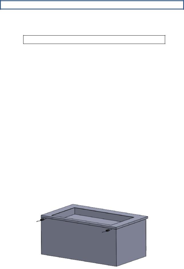
INSTALLATION
2.5Leveling, Bumpers and Shelves
2.5.3Shelves:
All cabinets with shelves are supplied with pilasters and shelf clip supports. Shelves are easily installed by inserting the shelf support clips into the pilasters so that they fit tightly.
Adjust the shelf so that the smaller fill wires run from front to rear and the shelf frame wire rest the shelf on the clips.
SHELVING ASEMBLY
|
9 |
809-112A Rev C |
2017-03-15 |
 Loading...