


MT45
IMPORTANT
INFORMATION
FOR
MM / MT / FC / Rl
SERIES
This cooler has passed the
QUALITY CONTROL INSPECTION
And meets the high standards at Beverage-Air
This inspection includes complete refrigeration
System, cabinet construction & finish.
IMPORTANT
PLEASE RETAIN FOR YOUR RECORDS
SALES OFFICE: P.O. BOX 5932 SPARTANBURG, S.C. 29304-5932
PHONE: (864) 582-8111 TOLL FREE 1-800-845-9800
TECHNICAL SERVICE: 1-800*684-1199, PARTS ORDER FAX: 1-800-262-9381
PLANTS: SPARTANBURG, S.C. BROOKVILLE, PA. HONEA PATH, S.C.
809-005A
Rev. E
1. Installation
BEVERAGE-AIR®
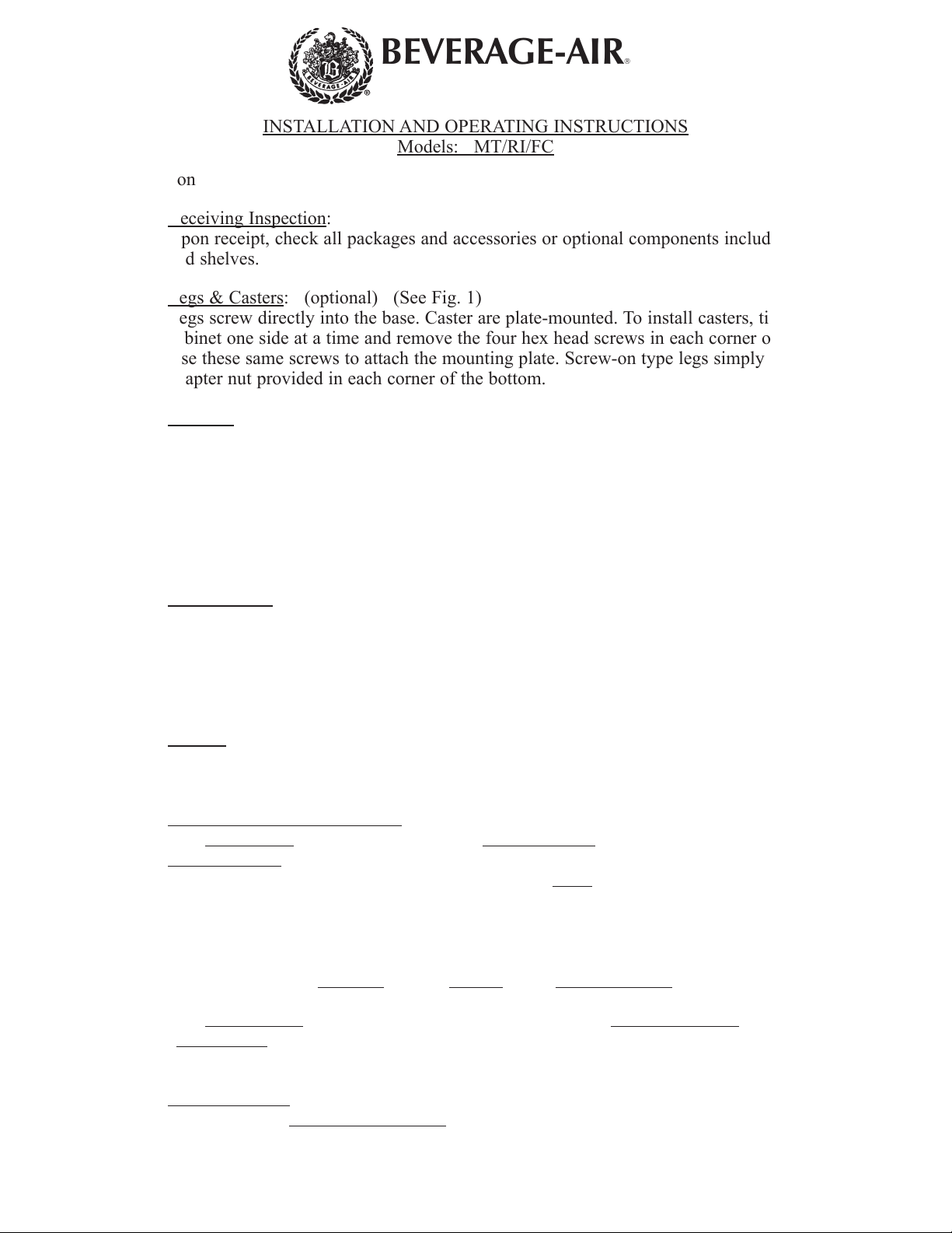
INSTALLATION AND OPERATING INSTRUCTIONS
Models: MT/RI/FC
ILA-0931
SHEET 1 OF 3
REV. B
a. Receiving Inspection
Upon receipt, check all packages and accessories or optional components including legs, casters,
and shelves.
b. Legs & Casters
Legs screw directly into the base. Caster are plate-mounted. To install casters, tip or raise the
cabinet one side at a time and remove the four hex head screws in each corner of the bottom.
Use these same screws to attach the mounting plate. Screw-on type legs simply screw into the
adapter nut provided in each corner of the bottom.
c. Leveling
To provide adequate condensate drainage and proper door alignment and operation. It is
necessary that the cabinet be level. Level cabinet from front to rear and from side to side with
leveling bolts, or leg inserts. This should be done after cabinet has been set in its final operating
position. The leveling bolts are the same bolts used to attach the wood base to the cabinet. BE
SURE THAT DRAIN HOSE IS ATTACHED AND DRAINING PROPERLY INTO EXTERIOR
CONDENSATE PAN LOCATED BEHIND BOTTOM GRILLE ASS’Y. THE HOSE COULD
POSSIBLE BE KNOCKED LOOSE IN TRANSIT.
d. Door Handles
Door handles with mounting screws are packed inside each cooler.
To mount handle, lift door gasket behind two holes in front and insert screws through the holes.
Attach handle, with offset away from cabinet corner, and tighten screws. (NOTE: It may be
necessary to adjust position of handle end mounts on handle bar to match hole spacing in door
frame.)
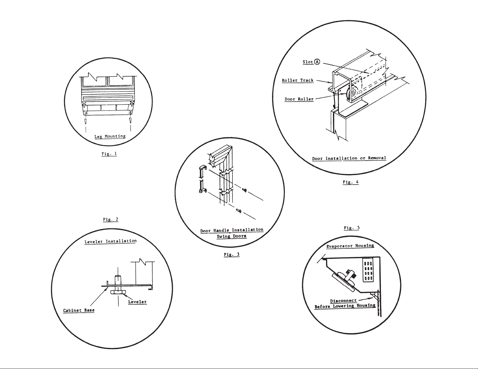
: (See Fig. 2)
: (optional) (See Fig. 1)
: (See Fig 3.)
:
e. Shelves
Shipped inside each cabinet are shelves packed in plastic and a bag of shelf supports. Shelf
spacing is adjustable to suit requirements. See Instruction Sheet ILA-0904 for installing.
f. Door Removal and
(1) Slide Doors
Proper
a. Locate Door Rollers under slot A
Adjust spring by moving hook to next hole or by shortening.
If door gaskets do not seal properly follow step 1 and 2.
Step 1: Check to see if cabinet base is level.
Step 2: Adjust the Location
(2) Swing Doors
“Swing Back
instructions see enclosed instruction sheet ILA-0859.
g. Locating Cooler
Provide at least three inches of space
end and rear of cabinet.
* For FC model, factory setting of temperature control is at No. 4 position (normal) which will
:
- Each door has its own Closing Spring located at the top and is positioned for
Tension. However if adjustment is required remove doors as follows:
bottom of door out.
” of doors, and does not require field adjustment. For replacement parts and
:
maintain the flower at about 42°F.
Adjustment:
show in fig. 4, and lift door off track while tilting
፨
of door Rollers in the Roller Brackets.
- Spring tension in the bottom hinges is Factory Adjusted for adequate
between cabinet and any adjacent wall or fixture, at left
2. Operation
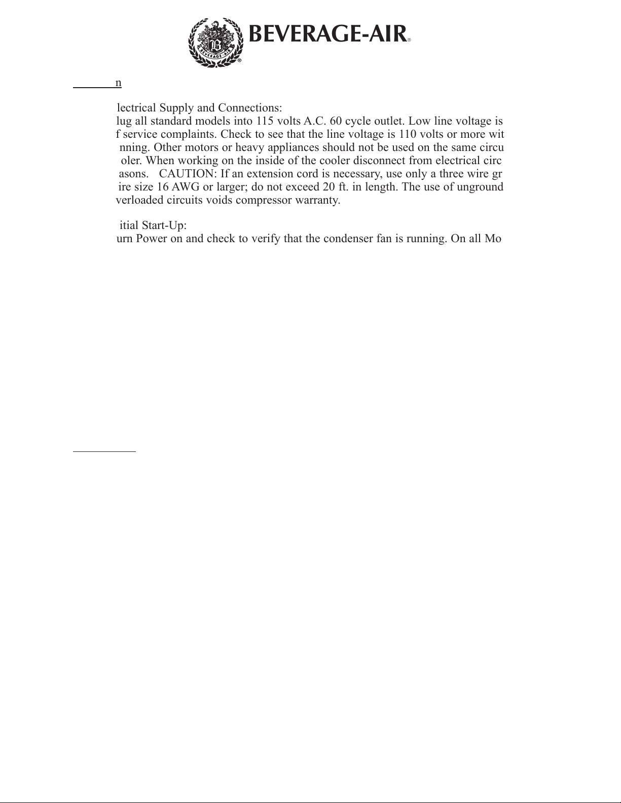
a. Electrical Supply and Connections:
Plug all standard models into 115 volts A.C. 60 cycle outlet. Low line voltage is often the cause
of service complaints. Check to see that the line voltage is 110 volts or more with the unit
running. Other motors or heavy appliances should not be used on the same circuit with the
cooler. When working on the inside of the cooler disconnect from electrical circuit for safety
reasons. CAUTION: If an extension cord is necessary, use only a three wire grounding type of
wire size 16 AWG or larger; do not exceed 20 ft. in length. The use of ungrounded cords or
overloaded circuits voids compressor warranty.
b. Initial Start-Up:
Turn Power on and check to verify that the condenser fan is running. On all Models, except
RI18, the defog fan and light switches are located on the blower housing front inside the
cabinet, the Defog Switch in “ON” position permits the Condenser Fan to run continuously for
maximum Door Defoging in high humidity locations.
c. Temperature Control:
Factory setting of temperature control is at No. 5 position (normal) which will maintain the
product at about 36°F.* For colder temperatures, turn knob clockwise one number at a time.
Excessive tampering with temperature control could lead to service difficulties. For operation
about 3000 ft. altitude, have thermostat adjusted by a qualified serviceman.
BEVERAGE-AIR®
ILA-0931
SHEET 2 OF 3
REV. B
d. Condensate Disposal:
The evaporator blower housing serves as a pan to collect and direct the condensate to the
evaporator pan located behind the front grille. Air flow over the pan hastens condensate
evaporation so that external drain plumbing is not required.
3. Maintenance
a. Cleaning Cabinet Exterior:
Cabinets should be cleaned with a solution of mild soap and water. Do not use caustic soap or
abrasive cleaners, since these might damage the cabinet finish. If stainless steel surface becomes
discolored, scrub by rubbing only in the direction of the finish grain. Do not use steel wool.
b. Cleaning Interior Surfaces:
The inside of the cabinet is coated with baked-on vinyl (except stainless steel cooler). To clean,
use mild soapy water and cloth or sponge.
c. Condenser:
For efficient operation, it is recommended that the condenser coil and fans be cleaned every
3 to 6 months. Remove front grille for access. Vacuum clean front surface of coil thoroughly or
direct forced air through condenser fins. Failure to clean condenser can cause compressor
malfunction and will void warranty.
d. Evaporator Fan:
Evaporator pan should be cleaned periodically to prevent odors and maintain evaporating
efficiency. The pan contains wicks to assist evaporation and should be replaced periodically.
e. Evaporator Housing:
If internal parts (e.g. fans, control) are to be serviced, lower housing as shown in (Fig 5). Make
certain to remove drain tube before lowering housing.
REV. B
SHEET 3 OF 3
ILA-0931
 Loading...