


CARRIER COMMERCIAL REFRIGERATION, INC.
Providing BEVERAGE-AIR • FRIGIDAIRE • KELVINATOR • UNIVERSAL NOLIN Products/Services
SERVICE &
INSTALLATION
MANUAL
MEDIUM
TEMPERATURE
VERTICAL
REFRIGERATORS
01/03 |
51-1337-02 |
|
|
If additional information is necessary, call the factory.
Our toll free number is 1-800-684-1199. Technical assistance engineers are willing to assist you in any way possible. Office hours are from 8:00 a.m. to 5:30 p.m., Eastern Standard Time.
Important information is contained in this manual which should be retained in a convenient location for future reference.
All data and information in this manual is subject to change without notice.
MODEL DESIGNATION INFORMATION
PART NO. |
MODELS |
STYLE |
CONDENSER |
SPECIAL USE |
52-1923-01 |
BT30RFEXPR |
SOLID ONE DOOR |
TOP MOUNT |
EXPLOSION PROOF |
52-1958-02 |
BT30RF-FMS |
SOLID ONE DOOR |
TOP MOUNT |
FLAMMABLE MAT'L STORAGE |
52-1993-33 |
BT30RG-4.1 |
GLASS ONE DOOR |
TOP MOUNT |
SCIENTIFIC GENERAL PURPOSE |
52-1993-34 |
BT30RGCH-4.1 |
GLASS ONE DOOR |
TOP MOUNT |
CHROMATOGRAPHY |
52-1993-35 |
BT30RS-4.1 |
SOLID ONE DOOR |
TOP MOUNT |
SCIENTIFIC GENERAL PURPOSE |
52-1993-29 |
BT30RSFMS-4.1 |
SOLID ONE DOOR |
TOP MOUNT |
FLAMMABLE MAT'L STORAGE |
52-1993-36 |
BT50RG-4.1 |
GLASS TWO DOOR |
TOP MOUNT |
SCIENTIFIC GENERAL PURPOSE |
52-1993-37 |
BT50RGCH-4.1 |
GLASS TWO DOOR |
TOP MOUNT |
CHROMATOGRAPHY |
52-1993-38 |
BT50RS-4.1 |
SOLID TWO DOOR |
TOP MOUNT |
SCIENTIFIC GENERAL PURPOSE |
52-1993-30 |
BT50RSFMS-4.1 |
SOLID TWO DOOR |
TOP MOUNT |
FLAMMABLE MAT'L STORAGE |
52-1993-39 |
BT80RG-4.1 |
GLASS THREE DOOR |
TOP MOUNT |
SCIENTIFIC GENERAL PURPOSE |
52-1993-32 |
ST260RIR-4.1 |
SOLID ONE DOOR |
TOP MOUNT |
INCUBATOR |
52-1993-41 |
ST30RGBB-4.1 |
GLASS ONE DOOR |
TOP MOUNT |
BLOOD STORAGE |
52-1993-42 |
ST50RGBB-4.1 |
GLASS TWO DOOR |
TOP MOUNT |
BLOOD STORAGE |
52-1991-64 |
T30MGP-4.1 |
GLASS ONE DOOR |
TOP MOUNT |
|
52-1991-65 |
T30MSP-4.1 |
SOLID ONE DOOR |
TOP MOUNT |
|
52-1991-66 |
T50MGP-4.1 |
GLASS TWO DOOR |
TOP MOUNT |
|
52-1997-36 |
T50MGPR-4.1 |
GLASS TWO DOOR |
TOP MOUNT |
|
52-1991-67 |
T50MSP-4.1 |
SOLID TWO DOOR |
TOP MOUNT |
|
52-1991-68 |
T80MGP-4.1 |
GLASS THREE DOOR |
TOP MOUNT |
|
52-1997-37 |
T80MGPR-4.1 |
GLASS THREE DOOR |
TOP MOUNT |
|
52-1992-32 |
UMG30BS-4.1 |
GLASS ONE DOOR |
BOTTOM MOUNT |
|
52-1992-33 |
UMG50BS-4.1 |
GLASS TWO DOOR |
BOTTOM MOUNT |
|
52-1997-34 |
UMG50RS-4.1 |
GLASS TWO DOOR |
BOTTOM MOUNT |
|
52-1992-34 |
UMG80BS-4.1 |
GLASS THREE DOOR |
BOTTOM MOUNT |
|
52-1997-35 |
UMG80RS-4.1 |
GLASS THREE DOOR |
BOTTOM MOUNT |
|
52-1992-35 |
UMH30BS-4.1 |
GLASS ONE DOOR |
BOTTOM MOUNT |
HEATED DOORS |
52-1992-36 |
UMH50BS-4.1 |
GLASS TWO DOOR |
BOTTOM MOUNT |
HEATED DOORS |
52-1992-37 |
UMH80BS-4.1 |
GLASS THREE DOOR |
BOTTOM MOUNT |
HEATED DOORS |
Manual effective for models produced January, 2003. Starting serial number .
TABLE OF CONTENTS-MED. TEMP. VERTICAL
MODEL CODES EXAMPLES .................................................. |
2 |
HANDLING & INSTALLATION .............................................. |
4 |
TOP MOUNT, GLASS PULL DOOR (1-,2-,& 3-DR MODELS) |
|
Dimensional Drawings .......................................................... |
6 |
Refrigerator Specifications.................................................... |
7 |
BOTTOM MOUNT, GLASS PULL DOOR (1-, 2-, 3-DR MODELS) |
|
Dimensional Drawings .......................................................... |
8 |
Refrigerator Specifications.................................................... |
9 |
TOP MOUNT, SOLID PULL DOOR (1 & 2-DR MODELS) |
|
Dimensional Drawings & Specifications ............................ |
10 |
MAINTENANCE & REPAIR ...................................... |
37 |
ELECTRICAL & REFRIGERATION INFORMATION
Medium Temperature Glass & Solid 1 Door |
......................15 |
Medium Temperature Glass & Solid 2 Door ...................... |
16 |
Medium Temperature Glass 3 Door .................................... |
17 |
Medium Temperature Solid 1 & 2 Door FMS...................... |
17 |
ELECTRICAL & REFRIGERATION INFORMATION
BT30RF-FMS |
|
Medium Temperature Solid 1 Door .................................... |
65 |
ELECTRICAL & REFRIGERATION INFORMATION
BT30RF-EXPR
Medium Temperature Solid 1 Door Refrigerator/Freezer ....69
ELECTRICAL & REFRIGERATION INFORMATION
ST260RI, ST260RIR |
|
Incubator ............................................................................ |
81 |
TROUBLESHOOTING ................................................ |
93 |
COMPONENT IDENTIFICATION ........................ |
100 |
PARTS LIST.................................................................... |
109 |
TABLE OF CONTENTS |
1 |
|
|

Medium Temperature Vertical Refrigerators
Introduction
These refrigerators have been designed to maintain a medium temperature environment. These multi-purpose refrigerators are available in one, two, and three-door solid or glass door models.
Except for routine cleaning, these medium temperature cabinets will require little maintenance. In the unusual event that repair should be necessary, this manual presents information that is helpful in maintaining, diagnosing, and repairing these cabinets.
2 |
INTRODUCTION |
|
|

MODEL CODES
Kelvinator Model Example: T30LGPR-4
T |
30 |
|
|
L |
G |
|
P |
|
R |
-4 |
||||||||||
|
|
|
|
|
|
|
|
|
|
|
|
|
|
|
|
|
|
|
|
|
T = Top Mount |
|
|
|
|
|
|
|
|
|
|
|
|
R = Remote |
|
|
|
||||
B = Bottom Mount |
|
|
|
|
|
|
|
|
|
|
|
|
E = Export |
|
|
|
||||
|
|
|
|
|
|
|
|
|
|
|
|
ET = Export Transformer |
|
|
|
|||||
FS = Food Service |
|
|
|
|
|
|
|
|
|
|
|
|
|
|
|
|||||
|
|
|
|
|
|
|
|
|
|
|
|
Customer Variations: |
|
|
|
|||||
|
|
|
|
|
|
|
|
|
|
|
|
|
|
|
|
|
|
|||
|
|
|
|
|
|
|
|
|
|
|
|
|
|
|
BR = Baskin Robbins |
|
|
|
||
|
|
|
30, 50, 80 - Cubic Feet |
|
|
|
|
|
|
|
|
|
|
|
|
|||||
|
|
|
|
|
|
|
|
|
|
|
|
DQ = Dairy Queen |
|
|
|
|||||
|
|
|
|
|
|
|
|
|
|
|
|
|
|
|
DQL = Dairy Queen Light Duty |
|
|
|||
|
|
|
|
|
|
|
|
|
|
|
|
|
|
|
||||||
|
|
|
|
|
|
L = Low Temp |
|
|
|
|
|
|
|
|
|
|
|
|
||
|
|
|
|
|
|
|
|
|
|
|
|
|
|
|
|
|
|
|||
|
|
|
|
|
|
M - Medium Temp |
|
|
|
P = Pull Door |
|
|
|
4 = Revision Level |
||||||
|
|
|
|
|
|
H = Hardening Cabinet |
|
|
|
S = Sliding Door |
|
|
|
|
|
|||||
|
|
|
|
|
|
|
|
|
|
|
|
|
|
|||||||
|
|
|
|
|
|
|
|
|
|
|
|
Q = Quadrant Pull Door |
|
|
|
|
|
|||
|
|
|
|
|
|
|
|
|
|
|
|
|
|
|||||||
|
|
|
|
|
|
|
|
|
G= Glass Door |
|
|
|
|
|
|
|
|
|
|
|
|
|
|
|
|
|
|
|
|
|
|
|
|
|
|
|
|
|
|
||
|
|
|
|
|
|
|
|
|
S = Solid Door |
|
|
|
|
|
|
|
|
|
|
|
|
|
|
|
|
|
|
|
|
|
|
|
|
|
|
|
|
|
|
|
|
Kelvinator Scientific Model Example: ESTL50RSFMS-4
E |
S |
TL |
50 |
R |
S |
FMS -4 |
|
|
|
|
|
|
|
|
|
|
|
E = Export |
|
|
|
|
|
|
|
|
||
ET = Export (Transformer) |
|
|
|
|
|
|
|
|
||
|
|
|
|
|
|
|
|
|
|
|
|
|
|
|
|
|
|
|
|
|
|
|
|
S = Scientific |
|
|
30, 50, 80 = |
|||||
|
|
B = Base Scientific |
|
|
Cubic Feet |
|||||
|
|
|
|
|
|
|
|
|
|
|
|
|
|
|
|
|
|
|
|
|
|
T = Top Mount
B = Bottom Mount
C = Chest
L = Hardening Cabinet
|
|
|
|
|
|
|
|
|
|
|
F = Freezer |
|
|
|
|
|
|
|
|
||
R = Refrigerator |
|
|
|
|
|
4 = Revision Level |
||||
|
|
|
|
|
|
|
|
|
|
|
|
|
|
|
|
|
|
|
|
|
|
|
|
G = Glass Door |
|
|
|
|
|
|||
|
|
S = Solid Door |
|
|
|
|
|
|||
|
|
I = Incubator (Solid Door) |
|
|
|
|
|
|||
|
|
|
|
|
|
|
|
|
|
|
|
|
|
|
|
|
|
|
|
|
|
FMS = Flammable Material Storage
CH = Chromatography
BB = Blood Bank
EXPR = Explosion Proof
R = Recorder on Incubator
Customer Variations:
XXX
MODEL CODES – KELVINATOR & KELVINATOR SCIENTIFIC |
3 |
|
|
MODEL CODES
Universal Nolin Model Example: UMG50BS-4
U |
M |
G |
50 |
B |
S |
-4 |
U = Upright
S = Scientific (upright)
L = Low Temp.
M = Med Temp.
H = Heated Glass (medium temp.) G = Glass
S = Solid
O = Open
T = Sliding Glass Door (track)
S = 115V / 60 Hz.
D = 208/230V / 60 Hz. / 1 Ph.
P = 208V / 60 Hz. / 3 Ph.
T = Transformer
F = 220V / 50 Hz.
30, 50, 80 =
Cubic Feet
4 = Revision Level
R = Remote on Bottom Mounted Upright
U - Remote on Top Mounted Upright
T = Top Mounted Compressor
B = Bottom Mounted Compressor
S = Single Facing (sliders)
D = Double Facing
4 |
MODEL CODES – UN |
|
|
SECTION I – HANDLING & INSTALLATION
FREIGHT DAMAGES & SHORTAGES
The cabinet was inspected and IMPORTANT: packaged at the factory, and should
arrive in excellent condition. The transportation company or other parties involved in the shipment are responsible for loss and/or damage. Always make an inspection before and after uncrating. Inspect the crated unit(s) before locating (preferably at the point of unloading by the transportation company).
The cabinet must be located so it can be plugged into a properly grounded three-prong electrical outlet of 115 volt, 60 hz. The electrical outlet should not be controlled by a wall switch which might be turned off accidentally.
UNCRATING THE CABINET
The cabinet should be moved as close as possible to the operating location before removing crate base. Be sure to follow the steps in the “INSPECTING FOR DAMAGES” instructions.
INSPECTING FOR DAMAGES
NOTE: Always use care when removing shipping tape, blocks, pads, hardware or other mate-
rial until you are satisfied that the unit is completely operational. Contact the factory if technical assistance is required.
Check the cartons or containers. If these are damaged in any way, open them and inspect the contents in the driver’s presence. If damage is detected:
1.Have the driver note the nature and extent of the damage on the freight bill.
2.Notify the transportation company at once to request an inspection. Carrier claim policies usually require inspections to be made within 15 days of delivery.
3.If damage is noticed, file a claim with the transportation company.
FILING A CLAIM
File a claim for loss at once with the transportation company for:
A. A cash adjustment; B. Repairs; or C. Replacement.
When filing your claim, retain all packaging materials and receipts.
HANDLING THE CABINET
NOTE: The refrigeration system of the cabinet is designed to operate with the cabinet located on a level surface. Do not tilt the cabinet more than
10° to any side. If the cabinet must be tilted on an angle for handling or moving purposes, allow it to sit in an upright position 30 minutes prior to starting.
CHOOSING A LOCATION
This model cabinet should be situated to allow proper air circulation. These cabinets require a 2" minimum clearance behind for proper air circulation.
The cabinet must be installed on sturdy, solid, level floor.
INSTALLING THE CABINET
(Models with Top Mounted Compressor)
Whenever possible leave the crate base on the cabinet until it is moved close to the final position. When it is necessary to move the cabinet through a doorway, it may be necessary to remove the crate base.
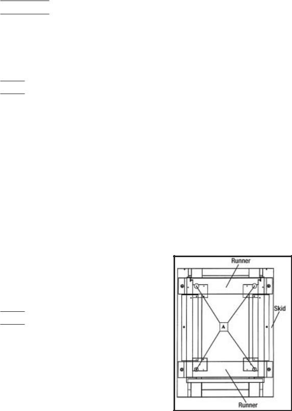
Wood runners are provided on the underside of the cabinet for ease in sliding. These runners should be left attached to the cabinet when the crate base is removed and should remain attached until after the legs are installed. The cabinet can then be pushed around more easily without scratching the floor. The runners also prevent damage to the electrical receptacle and condensate pan hardware on the cabinet bottom.
After the cabinet has been moved to the approximate final location, remove the package containing the legs from the cabinet interior. Tape the doors to prevent accidental opening when handling. Raise the sides of the cabinet high enough to mount the legs at the locations provided on the bottom of the cabinet.
IMPORTANT:
AFTER REMOVAL OF WOOD RUNNER, REPLACE BOLT “A” INTO LEG MOUNTING BRACKETS. THIS IS EXTREMELY IMPORTANT TO THE SECURE ATTACHMENT OF THE CABINET LEG. THERE MUST BE FOUR
(4) BOLTS SECURING EACH LEG.
Level the cabinet by means of the leg adjustments. Cabinet doors are self-closing, and the cabinet must be level to operate properly.
HANDLING & INSTALLATION |
5 |
|
|
CONDENSATE PAN INSTALLATION INSTRUCTIONS
MAKE SURE THE CABINET IS DISCONNECTED
FROM ITS POWER SOURCE
FIGURE 2
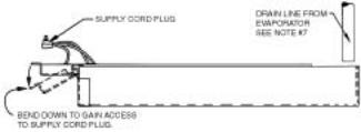
1.Remove and discard protective cover over electrical receptacle on bottom of cabinet
2.Bend down front part of housing. (See above.)
3.Insert condensate evaporator pan assembly into the slide supports on the underside of the cabinet by pushing toward back of cabinet until it stops.
4.Plug supply cord into receptacle in underside of cabinet.
5.Bend up front part of housing. Line up slot with rivnut in cabinet bottom and insert thumbscrew through slot onto rivnut in cabinet bottom. Insert thumb screw through slot onto rivnut and tighten.
6.The assembly will now operate when power is supplied to the cabinet.
7.Inspect rear of cabinet to ensure that the drain line from the evaporator is properly positioned over the condensate pan.
On top mount models, allow a minimum of twelve (12) inches between the top of the cabinet and ceiling and two (2) inches from the back of the cabinet to the wall.
(Models with Bottom Mounted Compressor)
Remove the crate base mounting clips located behind the front grill. Slide the cabinet forward on the crate base to clear the rear mounting clips.
After removing the crate base, move the cabinet into location. Make sure the cabinet is level to ensure operation of the “self-closing” doors.
Allow a minimum of two (2) inches between the back of the cabinet and the wall for proper air circulation through the condensing unit.
CABINET STARTUP
Once the cabinet has been located in its permanent location and the proper power and grounding have been provided, the following items must be checked or completed:
1.Cut and remove the compressor hold-down band (if applicable) so the compressor “floats” freely.
2.Check for traces of oil on the compressor pan which could mean a broken or leaking refrigeration line.
2.UNDER NO CIRCUMSTANCE SHOULD THE COMPRESSOR BE STARTED WHEN OIL IS PRESENT UNTIL INSPECTED BY A SERVICE TECHNICIAN.
3.INSPECT THE FACTORY WIRING FOR TERMINALS THAT MIGHT HAVE VIBRATED LOOSE IN SHIPPING. TIGHTEN ALL SCREW-TYPE TERMINALS.
4.Check the refrigeration lines to see that they are “free” and no damage was done during shipping.
5.Check fan blade(s) for “free” operation.
6.Turn on the main power switch. Once the compressor starts, the voltage should be checked at the compressor terminals to determine if there is proper voltage to the compressor. The voltage should not exceed 10% above or below the rated compressor voltage.
EXAMPLE: If the voltage reads 115 volts with no load and it drops below 103 volts when the compressor starts, it may indicate that the supply wiring is too small or that the wire run is too long.
7.Make sure that the drain line has not been dislodged or broken during shipping and that the drain trap terminates properly in the condensate pan or floor drain. (See Condensate Pan on top mounted compressor.)
8.Listen for any unusual noise such as lines vibrating, etc. Correct problem by tightening screws, slightly bending tubing, etc.
9.Check proper tension on doors. (See Door Torque Adjustment.)
10.Cabinet should not be loaded with product until cabinet has operated for 24 hours and reached desirable storage temperature.
THERMOSTAT SETTINGS
The refrigerator is shipped from the factory with a thermostat setting of approximately the mid-point of the operating range. Final thermostat setting must be made in the field.
Allow the cabinet to operate until the compressor cycles on the thermostat. The normal operating temperature range for the refrigerator is:
32°F to 55°F (0°C to 13°C)
NOTE: DO NOT OPERATE THE CABINET WITH THERMOSTAT SETTINGS BELOW 32°F (0°C).
The thermostat is easily adjusted with a standard screwdriver. The thermostat has settings 1 through 7, turn the thermostat to a higher number to lower the cabinet temperature.
The thermostat is located behind the evaporator front grill and can be adjusted through the grill. On some models the thermostat is located in the electrical box at the top of the cabinet.
SCIENTIFIC CONTROL AND
ANNUNCIATOR PANELS
Cabinets for Scientific use may be equipped with a variety of optional control, alarm, and recorder devices. Each cabinet is shipped with the appropriate operators manual for the device installed on the cabinet. These operator manuals pertain to the set-up and basic operation of the control panel devices. For more comprehensive operation, repair, and maintenance information refer to the control panel service manual part number 51-0170-01.
6 |
HANDLING & INSTALLATION |
|
|
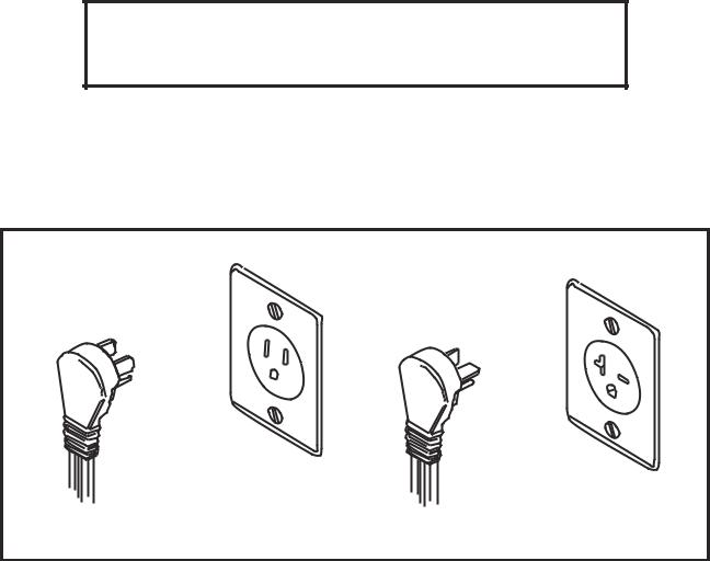
GROUNDING INSTRUCTIONS
This appliance is equipped with a three-prong (grounding) plug for your protection against shock hazards. The appliance should be plugged directly into a properly grounded three-prong receptacle.
Where a two-prong wall receptacle is encountered, it must be replaced with a properly grounded three prong receptacle in accordance with the National Electrical Code and local codes and ordinances. The work must be done by a licensed electrician.
IMPORTANT
Do not under any circumstances cut or remove the round grounding prong from the equipment plug.
WARNING
Consult a licensed electrician if you have any doubt about the grounding of your wall receptacle. Only a licensed electrician can determine the polarization of your wall receptacle. Only a properly installed three-pronged wall receptacle assures the proper polarization with the equipment plug.
15 Amp
20 Amp
SERIAL RATING PLATES
Serial Number Rating Plates on each vertical cabinet are located on the inside upper left hand corner. This plate contains all technical data necessary to the oper-
ation of the cabinet. Warranty administration is based on the serial number as printed on the rating plate.
GROUNDING INSTRUCTIONS/SERIAL RATING PLATES |
7 |
|
|
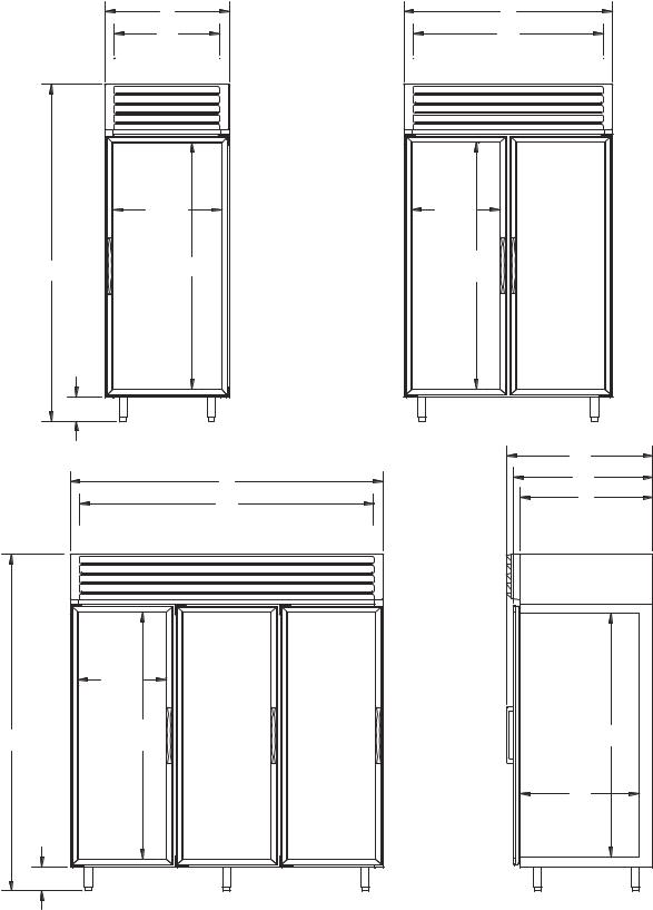
Medium Temperature, Top Mount, Glass Pull Door
Refrigerators Dimensional Drawings
31 |
52 |
261/4 |
471/4 |
INTERIOR |
INTERIOR |
|
263/4 |
215/8 |
|
|
GLASS |
GLASS |
|
|
|
TYP. |
|
|
61 |
61 |
|
833/4 |
GLASS |
||
GLASS |
|||
|
TYP. |
||
|
|
|
6 |
|
|
|
361/4 |
|
78 |
343/4 |
|
|
|
|
731/4 |
33 |
|
INTERIOR |
|
|
215/8 |
|
|
GLASS |
|
|
TYP. |
|
|
61 |
605/8 |
833/4 |
GLASS |
INTERIOR |
|
TYP. |
|
|
|
295/8 |
|
|
INTERIOR |
|
6 |
|
|
|
SIDE VIEW |
8 |
TOP MOUNT GLASS PULL DOOR DIMENSIONAL DRAWINGS |
|
|
Medium Temperature, Top Mount, Glass Pull Door
Refrigerators Specifications
Specification |
1-Door |
2-Door |
3-Door |
|
|
|
|
Compressor Mount |
Top |
Top |
Top |
|
|
|
|
Temperature Range |
32° to 55° (0° to 13°C) |
32° to 55° (0° to 13°C) |
32° to 55° (0° to 13°C) |
|
|
|
|
Number of Doors |
1 |
2 |
3 |
|
|
|
|
Door Construction |
Double Pane |
Double Pane |
Double Pane |
|
|
|
|
Hinge Type |
Torsion Bar |
Torsion Bar |
Torsion Bar |
|
|
|
|
Insulation - CFC-Free |
Foam-in-Place Urethane |
Foam-in-Place Urethane |
Foam-in-Place Urethane |
|
|
|
|
Wall Thickness |
2 3/8" |
2 3/8" |
2 3/8" |
|
|
|
|
Capacity - Gross |
27.3 ft.3 |
49.1 ft.3 |
76.2 ft.3 |
|
|
|
|
Shipping Weight (Approx.) |
470 lbs. |
640 lbs. |
870 lbs. |
|
|
|
|
Compressor BTUH/-10°F Evap. |
2400 |
5400 |
5400 |
|
|
|
|
Condenser Type |
Fin & Tube Forced Air |
Fin & Tube Forced Air |
Fin & Tube Forced Air |
|
|
|
|
Evaporator Type |
Fin & Tube Forced Air |
Fin & Tube Forced Air |
Fin & Tube Forced Air |
|
|
|
|
Refrigerant Type |
R-404A |
R-404A |
R-404A |
|
|
|
|
Refrigerant Control |
Expansion Valve |
Expansion Valve |
Expansion Valve |
|
|
|
|
Amp Rating |
9.5 |
12.1 |
14.5 |
|
|
|
|
|
11.2 BT30RG & ST30RGBB |
13.8 BT50RG & ST50RGBB |
16.0 BG80RG |
|
13.2 BT30RGCH |
15.8 BT50RGCH |
|
Electrical Specs. (V / Hz / Ph) |
115 / 60 / 1 |
115 / 60 / 1 |
115 / 60 / 1 |
|
|
|
|
NSF |
NSF7 |
NSF7 |
NSF7 |
|
|
|
|
UL & CSA Listed |
Yes |
Yes |
Yes |
|
|
|
|
Interior Finish |
Baked Enamel, Coved Corners |
Baked Enamel, Coved Corners |
Baked Enamel, Coved Corners |
Exterior Finish |
Baked Enamel |
Baked Enamel |
Baked Enamel |
Lighting |
2 Insul. 1500 Milliamp Fluor. Lamps |
3 Insul. 1500 Milliamp Fluor. Lamps |
4 Insul. 1500 Milliamp Fluor. Lamps |
|
|
|
|
Electrical Information |
15 Amp Service Cord |
20 Amp Service Cord |
20 Amp Service Cord |
|
w/NEMA 5-15P Plug |
w/NEMA 5-20 Plug |
w/NEMA 5-20P Plug |
|
20 Amp Cord BT30RGCH |
|
|
|
w/NEMA 5-20P Plug |
|
|
|
|
|
|
TOP MOUNT GLASS DOOR REFRIGERATOR SPECIFICATIONS |
9 |
|
|
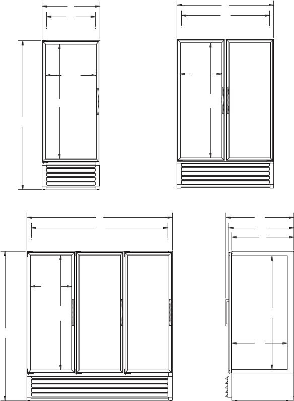
Medium Temperature, Bottom Mount, Glass
Pull Door Refrigerators Dimensional Drawings
31 |
52 |
||
26 |
1 |
/4 |
471/4 |
|
|
||
INTERIOR |
INTERIOR |
263/4 GLASS
61 GLASS
793/4
78
731/4 INTERIOR
215/8 GLASS TYP.
61 GLASS TYP.
793/4
215/8 GLASS TYP.
61 GLASS TYP.
361/4
343/4
33
605/8 INTERIOR
295/8 INTERIOR
SIDE VIEW
10 |
BOTTOM MOUNT DIMENSIONAL DRAWINGS |
|
|
Medium Temperature, Bottom Mount, Glass
Pull Door Refrigerators Specifications
Specification |
1-Door |
2-Door |
3-Door |
|
|
|
|
Compressor Mount |
Bottom |
Bottom |
Bottom |
|
|
|
|
Temperature Range |
32° to 55° (0° to 13°C) |
32° to 55° (0° to 13°C) |
32° to 55° (0° to 13°C) |
|
|
|
|
Number of Doors |
1 |
2 |
3 |
|
|
|
|
Door Construction |
Double Pane |
Double Pane |
Double Pane |
|
|
|
|
Hinge Type |
Torsion Bar |
Torsion Bar |
Torsion Bar |
|
|
|
|
Insulation - CFC-Free |
Foam-in-Place Urethane |
Foam-in-Place Urethane |
Foam-in-Place Urethane |
|
|
|
|
Wall Thickness |
2 3/8" |
2 3/8" |
2 3/8" |
|
|
|
|
Capacity - Gross |
27.3 ft.3 |
49.1 ft.3 |
76.2 ft.3 |
|
|
|
|
Shipping Weight (Approx.) |
488 lbs. |
640 lbs. |
724 lbs. |
|
|
|
|
Compressor BTUH/-10°F Evap. |
2400 |
5400 |
5400 |
|
|
|
|
Condenser Type |
Fin & Tube Forced Air |
Fin & Tube Forced Air |
Fin & Tube Forced Air |
|
|
|
|
Evaporator Type |
Fin & Tube Forced Air |
Fin & Tube Forced Air |
Fin & Tube Forced Air |
|
|
|
|
Refrigerant Type |
R-404A |
R-404A |
R-404A |
|
|
|
|
Refrigerant Control |
Expansion Valve |
Expansion Valve |
Expansion Valve |
|
|
|
|
Amp Rating |
9.5 |
12.1 |
14.5 |
|
|
|
|
Electrical Specs. (V / Hz / Ph) |
115 / 60 / 1 |
115 / 60 / 1 |
115 / 60 / 1 |
|
|
|
|
NSF |
NSF7 |
NSF7 |
NSF7 |
|
|
|
|
UL & CSA Listed |
Yes |
Yes |
Yes |
|
|
|
|
Interior Finish |
Baked Enamel, Coved Corners |
Baked Enamel, Coved Corners |
Baked Enamel, Coved Corners |
Exterior Finish |
Baked Enamel |
Baked Enamel |
Baked Enamel |
Lighting |
2 Insul. 1500 Milliamp Fluor. Lamps |
3 Insul. 1500 Milliamp Fluor. Lamps |
4 Insul. 1500 Milliamp Fluor. Lamps |
|
|
|
|
Electrical Information |
15 Amp Service Cord |
20 Amp Service Cord |
20 Amp Service Cord |
|
w/NEMA 5-15P Plug |
w/NEMA 5-20P Plug |
w/NEMA 5-20P Plug |
|
|
|
|
BOTTOM MOUNT REFRIGERATOR SPECIFICATIONS |
11 |
|
|
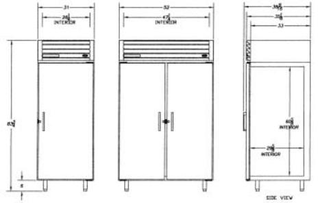
Medium Temperature, Top Mount, Solid Pull Door
Dimensional Drawings
Refrigerator Specifications
Specification |
1-Door |
2-Door |
|
|
|
Compressor Mount |
Top |
Top |
|
|
|
Temperature Range |
32° to 55° (0° to 13°C) |
32° to 55° (0° to 13°C) |
|
|
|
Number of Doors |
1 |
2 |
|
|
|
Door Construction |
Foam-In-Place |
Foam-In-Place |
|
|
|
Hinge Type |
Camlift |
Camlift |
|
|
|
Insulation |
Foam-in-Place Urethane |
Foam-in-Place Urethane |
|
|
|
Wall Thickness |
2 3/8" |
2 3/8" |
|
|
|
Capacity - Gross |
27.3 ft.3 |
49.1 ft.3 |
|
|
|
Shipping Weight (Approx.) |
440 lbs. |
604 lbs. |
|
|
|
Compressor BTUH/-10°F Evap. |
2126 |
2126 |
|
|
|
Condenser Type |
Fin & Tube Forced Air |
Fin & Tube Forced Air |
|
|
|
Evaporator Type |
Fin & Tube Forced Air |
Fin & Tube Forced Air |
|
|
|
Refrigerant Type |
R-404A |
R-404A |
|
|
|
Refrigerant Control |
Expansion Valve |
Expansion Valvee |
|
|
|
Amp Rating (80° Running) |
8.7 |
8.7 |
|
|
|
|
8.9 BT30RS |
8.9 BT50RS |
|
|
|
Electrical Specs. (V / Hz / Ph) |
115 / 60 / 1 |
115 / 60 / 1 |
|
|
|
NSF |
NSF7 |
NSF7 |
|
|
|
UL Listed |
Yes |
Yes |
|
|
|
Interior Finish |
Baked Enamel, Coved Corners |
Baked Enamel, Coved Cornerss |
Exterior Finish |
Baked Enamel |
Baked Enamel |
Compressor Make |
Tecumseh |
Tecumseh |
|
|
|
Electrical Information |
15 Amp Service Cord |
15 Amp Service Cord |
|
w/NEMA 5-15P Plug |
w/NEMA 5-15P Plug |
12 |
TOP MOUNT SOLID DOOR DRAWINGS & SPECIFICATIONS |
|
|

SECTION II

ELECTRICAL & REFRIGERATION SPECIFICATIONS
Medium Temp., Glass, 1-Door Refrigerators
SYSTEM COMPONENTS
Compressor Model Number |
Copeland ASE24C3E-IAA |
Recommended Operating Temp. Range |
32°F to 55°F (0°C to 13°C) |
Cabinet Volts |
115 |
Expansion Device |
Sporlan FBS 1/4C BP40 |
Charge Refrig. Type / Oz. / Grams |
R404A / 23 / 652.0 |
|
|
SYSTEM PERFORMANCE
AMBIENT |
70°F / 21.1°C |
80°F / 27°C |
90°F / 32.5°C |
|||
Cavity Temp. (F/C) |
40 / 4 |
40 / 4 |
41 / 5 |
|||
Suction Pressure (PSIG / Kpa) |
44 |
/ 303 |
45 |
/ 317 |
49 |
/ 338 |
Discharge Pressure (PSIG / Kpa) |
211 |
/ 1455 |
237 |
/ 1634 |
269 |
/ 1855 |
Compressor Amps |
|
6.3 |
|
6.3 |
|
6.5 |
Total Refrigeration Amps |
|
8.7 |
|
8.8 |
|
9.0 |
|
|
|
|
|
|
|
NOTE: REFER TO SERIAL DATA PLATE FOR REFRIGERANT TYPE & CHARGE.
Medium Temp., Solid, 1-Door Refrigerators
SYSTEM COMPONENTS
Compressor Model Number |
Americold HP121-1-3087 |
Recommended Operating Temp. Range (F/C) |
32°F to 55°F (0°C to 13°C) |
Cabinet Volts |
115 |
Expansion Device |
Capillary .054 x 7" |
Charge Refrig. Type / Oz. / Grams |
R404A / 15 / 425.2 |
|
|
SYSTEM PERFORMANCE
AMBIENT |
70°F / 21.1°C |
80°F / 27°C |
90°F / 32.5°C |
|||
Cavity Temp. (F/C) |
38 / 3 |
38 / 3 |
37 / 3 |
|||
Suction Pressure (PSIG / Kpa) |
39 |
/ 268 |
41 |
/ 283 |
45 |
/ 310 |
Discharge Pressure (PSIG / Kpa) |
192 |
/ 1324 |
217 |
/ 1496 |
247 |
/ 1703 |
Compressor Amps |
|
3.9 |
|
4.0 |
|
4.2 |
Total Refrigeration Amps |
|
5.7 |
|
5.8 |
|
6.0 |
|
|
|
|
|
|
|
1 DOOR (GLASS & SOLID) ELECTRICAL / REFRIGERATION SPECS 15

ELECTRICAL & REFRIGERATION SPECIFICATIONS
Medium Temp., Glass, 2-Door Refrigerators
SYSTEM COMPONENTS
Compressor Model Number |
Copeland AST54CIE-CAA |
Recommended Operating Temp. Range |
32°F to 55°F (0°C to 13°C) |
Cabinet Volts |
115 |
Expansion Device |
Sporlan FBS 1/4C BP405 |
Charge Refrig. Type / Oz. / Grams |
R404A / 23 / 652.0 |
|
|
SYSTEM PERFORMANCE
AMBIENT |
70°F / 21.1°C |
80°F / 27°C |
90°F / 32.5°C |
|||
Cavity Temp. (F/C) |
49 / 9 |
50 / 10 |
50 / 10 |
|||
Suction Pressure (PSIG / Kpa) |
48 |
/ 331 |
49 |
/ 332 |
50 |
/ 345 |
Discharge Pressure (PSIG / Kpa) |
238 |
/ 1641 |
271 |
/ 1868 |
306 |
/ 2110 |
Compressor Amps |
11.0 |
11.4 |
11.2 |
|||
Total Refrigeration Amps |
14.2 |
14.7 |
14.6 |
|||
|
|
|
|
|
|
|
NOTE: REFER TO SERIAL DATA PLATE FOR REFRIGERANT TYPE & CHARGE.
Medium Temp., Solid, 2-Door Refrigerators
SYSTEM COMPONENTS
Compressor Model Number |
Americold HP121-1-3087 |
Recommended Operating Temp. Range (F/C) |
32°F to 55°F (0°C to 13°C) |
Cabinet Volts |
115 |
Expansion Device |
Capillary .054 x 7" |
Charge Refrig. Type / Oz. / Grams |
R404A / 15 / 425.2 |
|
|
SYSTEM PERFORMANCE
AMBIENT |
70°F / 21.1°C |
80°F / 27°C |
90°F / 32.5°C |
|||
Cavity Temp. (F/C) |
40 / 4 |
40 / 4 |
39 / 4 |
|||
Suction Pressure (PSIG / Kpa) |
38 |
/ 262 |
42 |
/ 289 |
45 |
/ 310 |
Discharge Pressure (PSIG / Kpa) |
196 |
/ 1351 |
231 |
/ 1593 |
264 |
/ 1820 |
Compressor Amps |
|
3.9 |
|
4.2 |
|
4.4 |
Total Refrigeration Amps |
|
5.8 |
|
6.0 |
|
6.2 |
Center Mullion Heater |
2.5 watt / foot |
529 OHMS |
115V |
|||
|
|
|
|
|
|
|
16 2 DOOR (GLASS & SOLID) ELECTRICAL / REFRIGERATION SPECS

ELECTRICAL & REFRIGERATION SPECIFICATIONS
Medium Temp., Glass, 3-Door Refrigerators
SYSTEM COMPONENTS
Compressor Model Number |
Copeland AST54CIE-CAA |
Recommended Operating Temp. Range |
32°F to 55°F (0°C to 13°C) |
Cabinet Volts |
115 |
Expansion Device |
Sporlan FBS 1/2CP BP40 |
Charge Refrig. Type / Oz. / Grams |
R404A / 24 / 680.4 |
|
|
SYSTEM PERFORMANCE
AMBIENT |
70°F / 21.1°C |
80°F / 27°C |
90°F / 32.5°C |
|||
Cavity Temp. (F/C) |
36 / 2 |
37 / 3 |
35 / 2 |
|||
Suction Pressure (PSIG / Kpa) |
43 |
/ 296 |
42 |
/ 289 |
43 |
/ 296 |
Discharge Pressure (PSIG / Kpa) |
205 |
/ 1413 |
234 |
/ 1648 |
271 |
/ 1868 |
Compressor Amps |
10.0 |
|
9.6 |
|
9.8 |
|
Total Refrigeration Amps |
14.4 |
14.1 |
14.2 |
|||
|
|
|
|
|
|
|
NOTE: REFER TO SERIAL DATA PLATE FOR REFRIGERANT TYPE & CHARGE.
Medium Temp., Solid, 1 & 2 Door FMS
SYSTEM COMPONENTS
Compressor Model Number |
Americold HP110-1-3083 |
Recommended Operating Temp. Range (F/C) |
32°F to 55°F (0°C to 13°C) |
Cabinet Volts |
115 |
Expansion Device |
Capillary .049 x 5" |
Charge Refrig. Type / Oz. / Grams |
R404A / 15 / 425.2 |
|
|
SYSTEM PERFORMANCE
AMBIENT |
70°F / 21.1°C |
80°F / 27°C |
90°F / 32.5°C |
|||
Cavity Temp. (F/C) |
41 / 5 |
40 / 4 |
38 / 3 |
|||
Suction Pressure (PSIG / Kpa) |
39 |
/ 268 |
42 |
/ 290 |
46 |
/ 317 |
Discharge Pressure (PSIG / Kpa) |
172 |
/ 1186 |
196 |
/ 1351 |
229 |
/ 1579 |
Compressor Amps |
|
1.8 |
|
1.9 |
|
2.1 |
Total Refrigeration Amps |
|
3.3 |
|
3.4 |
|
3.5 |
|
|
|
|
|
|
|
3 DOOR (GLASS) & FMS ELECTRICAL / REFRIGERATION SPECS |
17 |
|
|

18
REFERENCE DIAGRAM WIRING
WIRING DIAGRAM REFERENCE
|
|
|
|
DOOR SWITCH, |
ANTI-SWEAT |
INCAND LIGHT, |
RECEPTACLE |
|
LIGHTS, |
|
CONTROL |
MODELS |
LADDER |
COMPRESSOR |
ELECT BOX |
RACEWAY |
HTR, RACEWAY |
RACEWAY |
BOX / LIGHT |
EVAPORATOR |
FLUORESCENT |
SOLENOID |
PANEL |
BT30RFEXPR |
26-0983-00 |
|
|
|
|
|
|
|
|
|
|
BT30RF-FMS |
00-0428-00 |
|
|
|
|
|
|
|
|
|
|
BT30RG-4.1 |
00-0052-00 |
00-0137-00 |
00-0056-00 |
|
|
|
|
00-0050-01 |
00-0067-01 |
|
00-0058-01/02 |
BT30RGCH-4.1 |
00-0052-00 |
00-0137-00 |
00-0056-00 |
|
|
|
00-0059-00 |
00-0050-01 |
00-0067-01 |
|
00-0058-01/02 |
BT30RS-4.1 |
00-0052-00 |
00-0071-00 |
00-0056-00 |
00-0061-01 |
|
00-0061-05 |
|
00-0050-01 |
|
|
00-0058-01 |
BT30RSFMS-4.1 |
00-0055-00 |
00-0071-00 |
00-0057-00 |
|
|
|
|
00-0050-04 |
|
|
00-0058-01 |
BT50RG-4.1 |
00-0052-00 |
00-0084-00 |
00-0056-00 |
|
00-0061-04 |
|
|
00-0050-01 |
00-0067-02 |
|
00-0058-01/02 |
BT50RGCH-4.1 |
00-0052-00 |
00-0084-00 |
00-0056-00 |
|
00-0061-04 |
|
00-0059-00 |
00-0050-01 |
00-0067-02 |
|
00-0058-01/02 |
BT50RS-4.1 |
00-0052-00 |
00-0071-00 |
00-0056-00 |
00-0061-02 |
00-0061-04 |
00-0061-05 |
|
00-0050-01 |
|
|
00-0058-01 |
BT50RSFMS-4.1 |
00-0055-00 |
00-0071-00 |
00-0057-00 |
|
|
|
|
00-0050-04 |
|
|
00-0058-01 |
BT80RG-4.1 |
00-0052-00 |
00-0084-00 |
00-0056-00 |
|
00-0061-04 |
|
|
00-0050-01 |
00-0067-03 |
|
00-0058-01/02 |
ST260RIR-4.1 |
00-0053-00 |
00-0071-00 |
00-0064-00 |
00-0061-01 |
00-0061-04 |
|
00-0065-00 |
00-0050-03 |
00-0065-00 |
|
00-0017-12 |
ST30RGBB-4.1 |
00-0052-00 |
00-0137-00 |
00-0056-00 |
00-0061-01 |
|
|
|
00-0050-01 |
00-0067-01 |
|
00-0017-10 |
ST50RGBB-4.1 |
00-0052-00 |
00-0084-00 |
00-0056-00 |
|
00-0061-04 |
|
|
00-0050-01 |
00-0067-02 |
|
00-0017-10 |
T30MGP-4.1 |
00-0052-00 |
00-0137-00 |
00-0056-00 |
|
|
|
|
00-0050-01 |
00-0067-01 |
|
|
T30MSP-4.1 |
00-0052-00 |
00-0071-00 |
00-0056-00 |
|
|
|
|
00-0050-01 |
|
|
|
T50MGP-4.1 |
00-0052-00 |
00-0084-00 |
00-0056-00 |
|
00-0061-04 |
|
|
00-0050-01 |
00-0067-02 |
|
|
T50MGPR-4.1 |
00-0052-00 |
|
00-0056-00 |
|
00-0061-04 |
|
|
00-0050-01 |
00-0067-02 |
00-0060-00 |
|
T50MSP-4.1 |
00-0052-00 |
00-0071-00 |
00-0056-00 |
|
00-0061-04 |
|
|
00-0050-01 |
|
|
|
T80MGP-4.1 |
00-0052-00 |
00-0084-00 |
00-0056-00 |
|
00-0061-04 |
|
|
00-0050-01 |
00-0067-03 |
|
|
T80MGPR-4.1 |
00-0052-00 |
|
00-0056-00 |
|
00-0061-04 |
|
|
00-0050-01 |
00-0067-03 |
00-0060-00 |
|
UMG30BS-4.1 |
00-0052-00 |
00-0137-00 |
00-0056-00 |
|
|
|
|
00-0050-01 |
00-0067-01 |
|
|
UMG50BS-4.1 |
00-0052-00 |
00-0084-00 |
00-0056-00 |
|
00-0061-04 |
|
|
00-0050-01 |
00-0067-02 |
|
|
UMG50RS-4.1 |
00-0052-00 |
|
00-0056-00 |
|
00-0061-04 |
|
|
00-0050-01 |
00-0067-02 |
00-0060-00 |
|
UMG80BS-4.1 |
00-0052-00 |
00-0084-00 |
00-0056-00 |
|
00-0061-04 |
|
|
00-0050-01 |
00-0067-03 |
|
|
UMG80RS-4.1 |
00-0052-00 |
|
00-0056-00 |
|
00-0061-04 |
|
|
00-0050-01 |
00-0067-03 |
00-0060-00 |
|
UMH30BS-4.1 |
00-0052-00 |
00-0137-00 |
00-0056-00 |
|
|
|
|
00-0050-01 |
00-0067-01 |
|
|
UMH50BS-4.1 |
00-0052-00 |
00-0084-00 |
00-0056-00 |
|
00-0061-04 |
|
|
00-0050-01 |
00-0067-02 |
|
|
UMH80BS-4.1 |
00-0052-00 |
00-0084-00 |
00-0056-00 |
|
00-0061-04 |
|
|
00-0050-01 |
00-0067-03 |
|
|
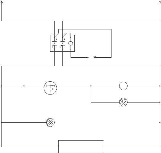
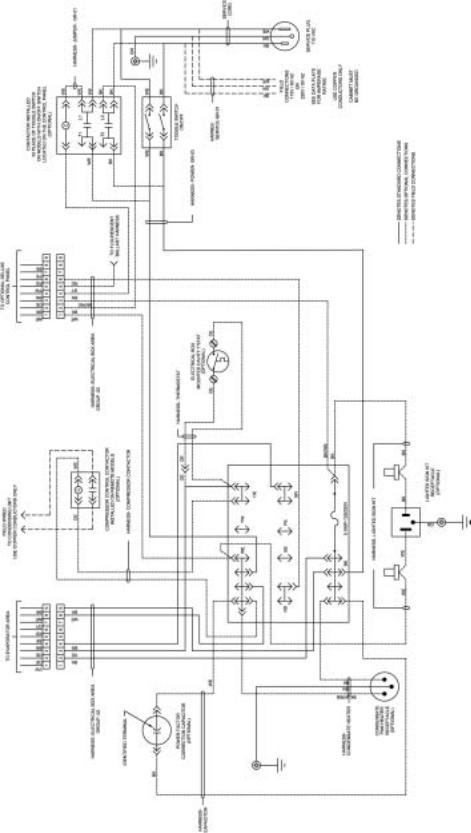
REFERENCE DIAGRAM WIRING

LADDER WIRING DIAGRAM – 00-0052-00
L1
BK
MED TEMP 115V, 60 HZ 220V, 50 HZ
ALL CONTROLS SHOWN IN OPERATING MODE |
SEE DATA PLATE FOR AMPERAGE RATING |
N |
|
|
|
CABINET MUST BE GROUNDED |
USE COPPER CONDUCTORS ONLY |
|
* DENOTES PIN NUMBER OF 9 PIN CONNECTOR |
|
WE |
|
|
DPST
POWER ON/OFF SWITCH
BK |
BK |
WE |
BK |
|
WE |
WE |
DPST |
POWER |
|
|
ON/OFF |
OPTIONAL |
SWITCH |
ON/OFF |
|
CSWITCH
|
AND |
BK |
OPTIONAL DELUXE |
WE |
|
CONTACTOR |
|||
|
|
CONTROL PANEL |
|
|
|
|
|
|
|
BN |
|
|
BLOOD BANK MODELS |
|
BK |
|
|
|
|
|
|
|
|
FIELD WIRED TO CONDENSING UNIT
USE COPPER CONDUCTORS ONLY
|
|
|
|
|
|
OE |
C |
WE |
|
|
|
|
|
|
|
|
|
|
|
|
|
COMP. CONTROL CONTACTOR |
|
|||
|
|
|
|
|
|
(REMOTE MODELS) |
|
|
|
|
|
|
|
|
OE |
WE |
|
|
|
|
|
LIQUID LINE SOLENOID VALVE |
|
|||
|
CAVITY T'STAT |
|
|
|
(REMOTE MODELS) |
|
||
BK |
OE |
|
OE |
OE |
|
OE |
M |
WE |
|
2 |
|
|
3 |
|
|
|
|
|
|
|
|
|
|
COMPRESSOR |
|
|
|
|
|
|
|
(SELF CONTAINED MODELS) |
|
||
|
|
|
|
|
|
OE |
|
WE |
|
|
|
|
|
|
COND FAN/S |
|
|
BK |
C |
NC |
RD |
|
WE |
(SELF CONTAINED MODELS) |
|
|
|
|
|
L |
|
|
|
|
|
OPTIONAL DOOR |
|
|
|
|
|
|
|
|
|
SWITCH/S |
OPTIONAL INCANDESCENT |
|
|
|
OPTIONAL |
|
|
|
|
|
INTERIOR LIGHT |
|
|
|
|
|
|
|
|
|
|
|
INDICATOR |
|
|
|
|
|
OR DOOR AJAR |
|
|
|
|
|
|
|
|
|
|
|
|
|
|
|
|
|
INDICATOR |
|
|
GY |
|
WE |
L
(MODELS WITH FLUORESCENT LIGHTING SYSTEM)
BN
|
BK/WE |
GY |
|
WE |
FUSE |
LIGHT SWITCH |
|
BALLAST/S |
|
|
|
BK |
WE |
|
OPTIONAL LIGHTED SIGN KIT |
|
RECEPTACLE |
|
|
BN |
WE |
|
WE |
WE |
|
|
|
|
8 |
EVAP FAN/S
BK |
BN |
BN |
WE |
|
9 |
4 |
|
|
|
BK |
|
|
|
|
|
|
OPTIONAL HEATED GLASS DOOR/S |
|
|
|
|
BN |
WE |
|
|
|
MULLION HEATERS/S |
|
|
|
|
(SOLID 2 & 3 DOOR MODELS) |
|
|
|
|
BK |
BK W/RIB |
|
|
|
OPTIONAL |
|
|
|
|
CONDENSATE PAN HEATER |
|
|
BK |
BK |
BK |
WE |
|
OPTIONAL CIRCUIT BREAKER |
|
|
|
|
OPTIONAL RECEPTACLES |
BK |
WE |
||
|
|
|||
|
|
BK |
WE |
|
BK |
OPTIONAL |
WE |
|
|
|
|
|
|
|
CHART RECORDER |
|
|
|
|
BK WE
OPTIONAL POWER
FACTOR CORRECTION P/N 00-0052-00 Rev A CAPACITOR 55 MFD
WIRING DIAGRAM |
19 |
|
|
LADDER WIRING DIAGRAM – 00-0053-00
INCUBATOR 115V, 60 HZ 220V, 50 HZ
ALL CONTROLS SHOWN IN OPERATING MODE
|
|
CABINET MUST BE GROUNDED |
|
|
* DENOTES PIN NUMBER OF 9 PIN CONNECTOR |
L1 |
N |
|
BK |
WE |
BK |
|
|
|
|
|
2 |
|
|
WE |
|
|
1 |
BK |
WE |
WE |
|
|
BN |
|
|
4 |
|
|
ON/OFF |
|
|
C |
|
|
CONTACTOR |
BK |
WE |
BN |
SEE DATA PLATE FOR AMPERAGE RATING
USE COPPER CONDUCTORS ONLY
BK |
|
WE |
TEMPERATURE BN |
|
MONITOR |
BN |
BK |
ON/OFF
SWITCH
DELUXE
CONTROL PANEL
|
BK |
2 |
OE |
3 |
OE |
|
|
OE |
WE |
|
|
|
|
|
|
|
M |
|
|
||
|
|
|
|
|
|
|
|
COMPRESSOR |
|
|
|
|
|
|
|
|
|
|
OE |
WE |
|
|
|
|
|
|
|
|
|
CONDENSOR FAN |
|
|
|
|
|
NC |
RD |
|
|
|
|
|
|
BK |
|
|
|
|
|
|
|
|
|
|
|
|
|
|
YW |
|
YW |
BN |
BN |
WE |
8 |
|
|
|
NO |
|
|
1 |
|
|
|
|
|
|
|
|
|
|
|
|
|
|
|
DOOR SWITCH |
|
|
|
|
4 |
|
EVAP FAN |
|
|
|
|
|
|
|
|
|
|
|
|
||
|
|
|
|
|
|
BN |
|
|
|
|
|
|
|
|
|
|
|
|
BN |
|
WE |
|
|
|
|
|
|
|
|
PERIMETER HEATER |
|
|
BK |
RD |
TEMP |
BE |
WE |
|
|
|
|
|
|
6 |
|
|
8 |
|
|
|
|
|
||
|
CONTROL |
|
|
|
|
|
|
|
||
|
|
|
|
PE |
PE |
RD |
|
BK |
GY |
WE |
|
|
|
|
|
7 |
5 |
|
|
|
7 |
|
DELUXE |
|
|
|
|
|
|
CAL-ROD |
|
|
|
|
|
|
|
|
|
|
|
|
|
CONTROL PANEL |
|
|
|
HIGH TEMP SAFETY |
|
|
||||
|
|
|
|
|
|
|
|
|||
|
|
|
|
|
|
|
T'STAT |
|
|
|
|
BK/WE |
|
|
OE |
YW |
5 |
GY |
|
|
|
|
|
|
|
|
3 |
|
L |
|
|
|
FUSE |
|
|
|
LIGHT SWITCH |
|
|
|
|
||
|
|
|
|
|
DELUXE |
|
INCANDESCENT |
|
|
|
|
|
|
|
|
|
INTERIOR LIGHT |
|
|
||
|
|
|
|
CONTROL PANEL |
|
|
|
|
||
|
|
|
|
|
|
RECEPTACLE |
|
|
||
BK |
|
|
BK |
|
|
BK |
WE |
|
|
|
CIRCUIT BREAKER |
|
|
|
|
|
|
|
|
|
|
|
|
|
BK |
|
|
BK W/RIB |
|
|
|
|
|
CONDENSATE PAN HEATER |
|
|
P/N 00-0053-00 |
|
|
||||
20 |
WIRING DIAGRAM |
|
|
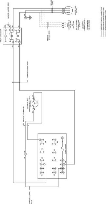
LADDER WIRING DIAGRAM – 00-0055-00
MEDIUM TEMP SCIENTIFIC 115V, 60 HZ 220V, 50 HZ
ALL CONTROLS SHOWN IN OPERATING MODE.
SEE DATA PLATE FOR AMPERAGE RATING
USE COPPER CONDUCTORS ONLY
CABINET MUST BE GROUNDED
L1 |
|
|
|
N |
BK |
|
|
|
WE |
|
|
BK |
|
|
|
|
WE |
|
|
|
|
ON/OFF |
|
|
|
|
SWITCH |
|
|
|
|
C & CONTACTOR |
|
|
|
|
BN |
BK |
|
|
BK |
WE |
|
|
|
CAVITY |
|
|
|
|
T'STAT |
|
COMPRESSOR |
|
|
|
|
|
|
BK |
OE |
OE |
OE |
WE |
|
|
|
M |
|
|
|
|
OE |
WE |
|
|
CONDENSOR FAN/S |
|
|
|
BK |
BK W/RIB |
|
|
|
EVAPORATOR FAN/S |
|
|
|
|
BK |
OPTIONAL |
WE |
|
|
|
|
|
|
|
|
CHART RECORDER |
|
|
|
|
|
P/N 00-0055-00 |
|
WIRING DIAGRAM |
21 |
|
|
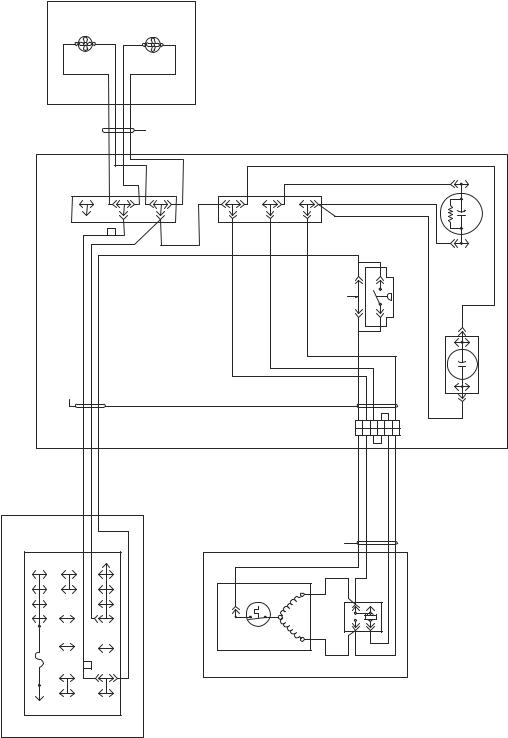
COMPRESSOR WIRING DIAGRAM – 00-0071-00
|
|
|
F |
CONDENSOR FAN #1 |
|
F |
CONDENSOR |
FAN #2 (OPTIONAL) |
CONDENSOR FAN ASSY |
|
|
|
|
NOTES- |
STANDARD CONNECTIONS SHOWN WITH SOLID LINES; OPTIONAL CONNECTIONS SHOWN WITH DASHED LINES. |
F FORWARD ROTATION CONDENSOR FAN |
(NORMAL OPERATION) |
|
|
|
|
|
|
|
|
|
|
|
|
CONDENSOR |
FAN LEADS |
|
|
|
|
|
1) |
2) |
|
|
|
|
|
|
|
|
|
BOARD |
|
|
BK |
BK |
BKORWE |
WE |
BKORWE |
|
WE |
BK |
BK |
BE |
|
|
|
|
|
|
|
|
|
|
TERMINAL |
|
|
F |
|
|
|
|
RD |
|
|
|
|
KB |
|
|
|
|
|||
|
|
|
|
|
|
|
|
|
|
|
|
|
|
|
|
KB |
|
|
|
|
|
|
|
|
|
|
|
EO |
|
|
|
|
|
|
|
|
|
|
|
|
|
|
|
|
|
|
|
|
|
|
|
EW |
|
|
|
|
|
|
|
|
|
|
|
|
|
|
|
|
|
|
|
|
|
OE |
|
|
|
|
|
|
|
|
|
|
|
|
|
|
|
|
|
|
START BOX ASSY |
115V, 60 HZ |
220V, 50 HZ |
|
|
|
|
|
|
|
|
|
|
|
JUMPER (REMOVE WHEN |
INSTALLING PRESSURE SWITCH) |
OE |
|
|
|
|
PRESSURE SWITCH (OPTIONAL) |
|
|
HARNESSSTART |
GR-01 |
|
|
|
|
|
|
|
|
|
|
|
|
|
|
|
|
|
|
|
|
|
|
|
|
|
|
|
|
|
|
|
|
|
|
|
|
6 |
5 |
4 |
3 |
2 |
1 |
|
|
|
|
|
|
|
|
|
|
|
|
|
|
|
|
|
6 |
5 |
4 |
3 |
2 |
1 |
|
|
|
|
|
|
|
|
|
|
|
|
|
|
|
HARNESSCOMPRESSOR GR-01 |
|
|
|
|
|
|
|
BOXELECTRICALASSY |
125/250V-AMP |
RD |
|
WEYW |
BLOCKTERMINAL |
|
|
|
ASSY |
COMPRESSOR |
|
|
SR |
RELAY |
PIN PIN |
OE |
|
|
|
|
|
|
BEPE |
|
F |
|
|
|
AMERICOLDCOMPRESSOR |
O.L. |
C |
BE |
RD |
4 |
|
|
|
||||||||
|
|
|
|
|
|
|
|
|
|
|
|
|
|
|
|
|
WE |
|
|
|
|
|
|
BK |
|
|
|
|
|
|
|
|
|
|
|
|
|
|
|
|
|
|
|
|
|
|
|
|
|
|
|
|
|
|
|
|
|
|
|
|
|
|
2 |
|
1 |
|
|
|
|
|
|
|
|
|
|
|
|
|
|
|
|
|
|
|
|
3 |
|
|
|
|
|
|
5 |
|
|
|
|
|
|
|
|
|
|
|
|
|
|
|
|
|
|
|
|
|
|
|
BN |
|
|
OE |
|
|
|
|
|
|
|
|
|
|
|
|
|
|
|
|
|
START CAP
BK
RUN CAP
BK
22 |
WIRING DIAGRAM |
|
|
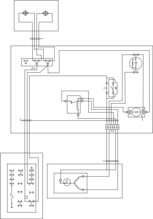
COMPRESSOR WIRING DIAGRAM – 00-0084-00
|
|
F |
CONDENSOR FAN #1 |
F |
CONDENSOR |
FAN #2 (OPTIONAL) |
CONDENSOR FAN ASSY |
|
|
|
|
|
|
CONDENSOR |
FAN LEADS |
|
|
|
BOARD |
|
BK |
BK |
BKORWE |
|
BKORWE |
|
|
TERMINAL |
|
F |
|
|
|
|
|
|
|
|
|
|
WE |
|
|
|
|
|
|
EO |
|
|
|
|
|
|
|
|
|
EW |
|
|
|
|
|
|
|
OE |
|
|
|
|
|
START BOX ASSY |
115V, 60 HZ |
220V, 50 HZ |
|
|
|
|
1 |
Z |
|
HARNESSSTART |
GR-02 |
|
|
|
|
RELAY |
5 |
RD
ELECTRICALBOX ASSY |
125/250V-AMP |
PE BE |
F |
YW WE |
TERMINALBLOCK |
COPELAND AST54 COMPRESSORASSY |
COMPRESSOR |
O.L. |
C |
SR |
|
BK |
|
|
|
|
|
|
|
|
|
|
5 |
|
|
|
|
|
|
|
|
|
|
|
BN |
|
OE |
|
|
|
|
|
|
NOTES- |
STANDARD CONNECTIONS SHOWN WITH SOLID LINES; |
OPTIONAL CONNECTIONS SHOWN WITH DASHED LINES. |
F FORWARD ROTATION CONDENSOR FAN |
(NORMAL OPERATION) |
1) |
|
2) |
|
|
|
|
|
|
|
|
|
WE |
|
|
|
|
|
|
|
|
|
|
|
START CAP |
|
|
|
|
|
|
|
|
|
|
|
BN |
|
|
|
|
JUMPER (REMOVE WHEN INSTALLING PRESSURE SWITCH) |
OE |
|
|
|
|
|
PRESSURE SWITCH (OPTIONAL) |
|
WE |
WE |
|
|
|
|
|
|
|
|
BE |
|
|
|
|
|
OE |
WE |
BN |
YW |
RD |
BE |
RUN CAP |
IDENTIF IED |
TERMIN AL |
|
|
|
|
6 |
5 |
4 |
3 |
2 |
1 |
|
|
|
|
|
|
6 |
5 |
4 |
3 |
2 |
1 |
|
|
|
115V, 60 HZ 220V, 50 HZ |
COMPRESSOR GR-05 |
|
|
|
|
|
|
|
|
|
|
|
HARNESS- |
|
|
|
|
|
|
|
|
|
|
|
OE |
|
|
|
|
|
|
|
|
|
|
|
WE |
|
|
|
|
|
|
|
|
|
|
|
BE |
|
|
|
|
|
|
|
|
|
|
WIRING DIAGRAM |
23 |
|
|
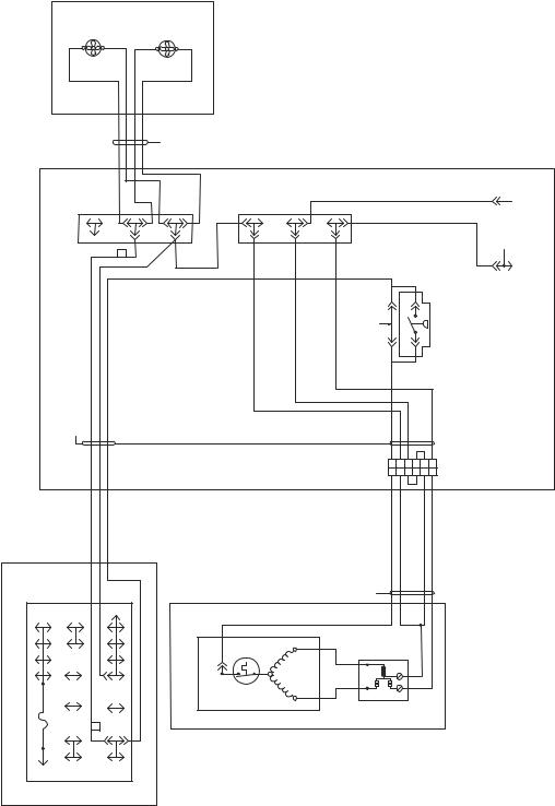
COMPRESSOR WIRING DIAGRAM – 00-0137-00
|
|
|
F |
CONDENSOR FAN #1 |
|
F |
CONDENSOR |
FAN #2 (OPTIONAL) |
CONDENSOR FAN ASSY |
|
|
|
NOTES- |
STANDARD CONNECTIONS SHOWN WITH SOLID LINES; |
OPTIONAL CONNECTIONS SHOWN WITH DASHED LINES. |
F FORWARD ROTATION CONDENSOR FAN |
(NORMAL OPERATION) |
|
|
|
|
|
|
|
|
CONDENSOR |
FAN LEADS |
|
|
|
|
1) |
|
2) |
|
|
|
|
|
BOARD |
|
|
BK |
BK |
BKORWE |
WE |
BKORWE |
WE |
|
RD |
BK |
|
|
|
|
|
|
|
TERMINAL |
|
|
F |
|
|
|
|
BE |
|
|
|
|
KB |
|||
|
|
|
|
|
EO |
|
|
|
|
|
|
|
|
|
|
|
|
|
|
|
|
|
|
|
EW |
|
|
|
|
|
|
|
|
|
|
|
|
|
|
|
|
|
OE |
|
|
|
|
|
|
|
|
|
|
|
|
|
|
START BOX ASSY |
115V, 60 HZ |
220V, 50 HZ |
|
|
|
|
|
|
|
|
|
|
|
JUMPER (REMOVE WHEN |
INSTALLING PRESSURE SWITCH) |
OE |
|
|
|
HARNESSSTART |
GR-01 |
|
|
|
|
|
|
|
|
|
|
|
|
|
|
|
|
|
|
|
|
|
|
|
|
|
|
|
|
|
|
|
|
6 |
5 |
|
|
|
|
|
|
|
|
|
|
|
|
|
|
|
|
|
6 |
5 |
|
|
|
|
|
|
|
|
|
|
|
|
|
|
115V, 60 HZ |
220V, 50 HZ COMPRESSOR GR-01 |
|
|
|
|
|
|
|
|
|
|
|
|
|
|
|
|
|
|
HARNESS- |
|
WE |
|
|
|
RD |
|
|
|
|
|
|
|
|
|
|
|
|
|
|
|
|
ELECTRICALBOX ASSY |
125/250V-AMP |
PEBE |
|
|
YWWE |
TERMINALBLOCK |
|
COPELANDASE24 COMPRESSORASSY |
COMPRESSOR |
|
|
SR |
|
|
|
|
OE |
|
|
F |
|
O.L. |
C |
|
|
S M |
|
|
|
||||||||
|
BK |
|
|
|
|
|
|
|
|
|
|
|
|
|
|
|
|
|
|
|
|
|
|
|
|
|
|
|
|
|
|
|
|
|
|
|
2 |
|
|
|
|
|
|
|
|
|
|
|
|
|
|
|
|
|
|
1 |
|
|
|
|
|
|
|
|
|
|
|
|
|
|
|
|
|
RELAY |
|
|
5 |
|
|
|
|
|
|
|
|
|
|
|
|
|
|
|
|
|
|
|
BN |
|
|
OE |
|
|
|
|
|
|
|
|
|
|
|
|
|
PRESSURE SWITCH |
(OPTIONAL) |
4 |
3 |
2 |
1 |
4 |
3 |
2 |
1 |
RD
WE
BE
 START CAP
24 |
WIRING DIAGRAM |
|
|
ELECTRICAL BOX WIRING DIAGRAM – 00-0056-00
WIRING DIAGRAM |
25 |
|
|
ELECTRICAL BOX WIRING DIAGRAM – 00-0057-00
26 |
WIRING DIAGRAM |
|
|

ELECTRICAL BOX WIRING DIAGRAM – 00-0064-00
WIRING DIAGRAM |
27 |
|
|

28
DIAGRAM WIRING
HARNESSDOOR SWITCH GROUP -01
BLACK TAPE
RD
OE |
BK |
YW
DOOR 1
MED. TEMP & INCUBATOR MODELS
LOW TEMP "PULSE" MODELS
REMOVE "OE" WIRE ON MED. TEMP & INCUBATOR MODELS
LOW TEMP MODELS
*GR-01 |
1 DOOR VERTICAL MODELS |
|
|
|||
|
OPTIONAL DOOR SWITCH |
|
|
|
||
|
|
|
HARNESSDOOR SWITCH GROUP -02 |
|||
BLACK TAPE |
|
RD |
|
RD |
||
|
|
|
|
|||
OE |
|
BK |
|
|
|
|
|
|
|
YW |
C |
YW |
|
|
|
|
|
|
NO |
|
|
MED. TEMP MODELS |
DOOR 1 |
|
DOOR 2 |
||
|
|
|
|
|
||
|
LOW TEMP "PULSE" MODELS |
|
|
|
||
|
REMOVE "OE" WIRE ON MED. TEMP MODELS |
|
|
|
||
|
LOW TEMP MODELS |
|
|
|
|
|
*GR-02 |
2 DOOR |
VERTICAL MODELS |
|
|
||
|
OPTIONAL DOOR SWITCHES |
|
|
|
||
|
|
|
HARNESSDOOR SWITCH GROUP -03 |
|||
BLACK TAPE |
|
|
|
|
||
|
RD |
|
RD |
|
RD |
|
OE |
BK |
|
|
|
|
|
|
YW |
C |
YW |
C |
YW |
|
|
|
|
NO |
|
NO |
|
|
DOOR 1 |
|
DOOR 2 |
|
DOOR 3 |
|
|
MED. TEMP MODELS |
|
|
|
|
|
|
LOW TEMP "PULSE" MODELS |
|
|
|
||
|
REMOVE "OE" WIRE ON MED. TEMP MODELS |
|
|
|
||
*GR-03 |
LOW TEMP MODELS |
|
|
|||
3 DOOR VERTICAL MODELS |
OPTIONAL DOOR SWITCHES |
|||||
|
||||||
|
TERMINAL BLOCK |
||
|
|
YW |
|
|
WE |
|
OE |
RD |
BE |
|
|
|
|
PE |
BN |
|
BK |
5 AMP-125/250V |
|
|
TIME CLOCK |
||
|
T |
|
|
|
3 |
4 |
X |
|
1 2 |
N |
|
OE
ELECTRICAL BOX ASSY
|
TERMINAL BLOCK |
||
|
|
YW |
|
|
WE |
|
OE |
RD |
BE |
|
|
|
|
PE |
BN |
|
BK |
5 AMP-125/250V |
|
|
TIME CLOCK |
||
|
T |
|
|
|
3 |
4 |
X |
|
1 2 |
N |
|
OE
ELECTRICAL BOX ASSY
|
TERMINAL BLOCK |
||
|
|
YW |
|
|
WE |
|
OE |
RD |
BE |
|
|
|
|
PE |
BN |
|
BK |
5 AMP-125/250V |
|
|
|
|
|
|
TIME CLOCK |
||
|
T |
|
|
|
3 |
4 |
X |
|
1 2 |
N |
|
OE
ELECTRICAL BOX ASSY
|
|
|
|
|
|
|
|
BATTERY BACKUP |
|
|
|
|
|
|
|
|
|
|
|
|
|
|
|
|
|
|
|
4 |
3 |
|
|
|
|
|
|
|
|
|
|
|
|
|
|
BK |
RD |
5 |
2 |
|
|
|
|
|
|
|
|
|
|
|
|
|
|
6 |
1 |
|
|
|
|
|
|
||
|
|
|
|
|
|
|
|
02 |
|
03 |
|
|
|
|
|
|
|
|
|
|
|
|
|
|
|
|
PUSHBUTTON |
|
|
|
|
|
|
|
|
|
|
|
|
|
|
|
|
02 |
|
|
|
|
|
|
|
|
|
|
|
|
|
|
|
|
|
SWITCH |
|
|
|
|
|
|
|
|
|
|
|
|
|
|
|
|
|
|
|
03 |
|
|
|
|
|
|
|
|
|
|
DOOR SWITCH TERMINAL NUMBERS |
+ |
- |
|
HARNESSDOOR SWITCH |
|
|
|
|
|
|
|
|
||
|
|
|
|
|
|
|
|
|
|
|
|
|
|
|
|
||
ARCOELECTRIC |
McGILL |
|
+ |
- |
+ |
- |
GROUP04 |
|
|
|
|
|
|
|
|
||
CARLINGSWITCH |
RD |
BK |
RD |
BK |
|
|
|
|
|
|
DISPLAY |
||||||
|
|
|
|
|
|
|
|
|
|
|
|
|
|
|
|||
|
|
|
|
|
|
RECTIFIER |
|
|
|
1 |
2 |
3 |
4 |
1 |
2 |
3 |
|
|
|
|
1 |
3 |
|
BK |
RD |
01 |
01 |
|
|
|
|
|
|
|
|
|
|
|
2 |
2 |
|
|
|
|
|
|
TERMINAL BLOCK |
||||||
2 |
3 |
1 |
3 |
1 |
|
|
|
|
|
|
|||||||
NC |
NO |
C |
|
|
|
|
|
BLACK TAPE |
RD |
|
|
|
|
|
|
YW |
|
(RED) |
|
|
|
|
|
|
|
|
|
WE |
|
|
|
|
|
OE |
|
|
|
|
|
|
|
|
BK |
|
|
|
|
|
|
||||
|
|
|
|
|
|
|
|
RD |
BE |
|
|
|
|
||||
|
|
|
|
|
|
|
|
|
|
|
|
|
|
||||
|
|
|
|
|
|
|
|
|
YW |
|
|
|
|
|
PE |
BN |
|
|
|
|
|
|
|
|
|
|
|
|
|
|
|
|
|||
|
|
|
|
|
|
BK |
|
|
|
|
|
|
|
|
|
|
|
|
|
|
|
|
HEATER |
|
|
BN |
DOOR SWITCH |
|
BK |
|
|
|
5 AMP-125/250V |
||
|
|
|
|
|
|
|
|
|
|
|
|
|
|
|
|
|
|
|
|
|
|
|
|
WE |
WE |
|
|
|
|
|
|
|
|
|
|
|
|
|
|
|
PERIMETER |
|
*GR-06 |
UNDER COUNTER MODELS |
ELECTRICAL BOX ASSY |
||||||||
|
|
|
"PULSE" |
|
|
|
HARNESS- ANTI-SWEAT HEATER |
|
|
|
|
|
|
|
|
||
|
|
|
|
|
|
|
|
|
|
|
|
|
|
|
|||
4 |
3 |
(OPTIONAL) |
5 |
2 |
|
6 |
1 |
|
|
|
|
|
|
|
|
|
|
|
|
|
|
|
|
|
|
WE |
YW |
OE |
|
|
|
|
|
|
|
|
|
|
|
|
|
|
|
|
|
RD |
|
|
|
|
|
|
|
|
|
|
|
|
|
|
|
|
|
|
|
BE |
PE |
BN |
|
|
|
|
|
|
|
|
|
|
WE |
WE |
|
BN |
|
|
BN |
BK |
5 AMP-125/250V |
|
|
|
|
|
DISPLAY |
|
|
|
|
|
|
|
|
|
|
|
|
|
||
1 |
2 |
3 |
4 |
1 |
2 |
3 |
|
|
|
|
|
|
|
|
|
|
|
|
|
|
|
|
|
|
|
|
|
|
|
|
|
|
|
|
|
|
ELECTRICAL BOX ASSY |
||
|
|
|
|
1 |
2 |
3 |
|
|
|
|
|
|
|
|
|
|
|
|
|
|
|
|
|
|
|
|
CUT |
WE |
WE |
WE |
WE |
TERMINAL BLOCK |
BN |
BN |
BN |
BN |
|
|
|
|
|
|
|
|
|
|
WIRES |
RACEWAY |
|
|
|
||||||||
|
|
|
|
BK |
GN |
RD |
|
|
|
|
|
|
|
|
|
|
HARNESSSHORT MULLION HEATER |
|
|
|
|
|
|
WE |
|
BN |
WE |
BK GN RD BN |
|
|
|
|
|
|
|
|
|
|
|
GLASS HEAT
DOOR RECEPTACLE (OPTIONAL)
GN |
GN |
GN |
PULSE |
PULSE |
NON-PULSE |
PERIMETER HEATER |
MULLION HEATER |
|
MODELS |
MODELS |
MODELS |
|||
(OPTIONAL) |
2 & 3 DOOR MODELS |
||||
DOOR |
DOOR |
|
|||
|
|
(OPTIONAL) |
|||
W/DISPLAY |
W/0 DISPLAY |
|
|
||
|
|
|
BN
BK |
BK |
|
WE |
WE |
WE |
ALL VERTICAL MODELS
|
|
|
|
SHORT MULLION HEATER |
OPTIONAL ANTI-SWEAT HTRS |
HARNESSDISPLAY |
(QUAD-DOOR HARDENING |
||||
|
|
|
|
CABINETS ONLY) |
OPTIONAL HEATED DOOR |
|
3 |
|
PULSE DISPLAY IN SOLID DR FRT PANEL |
|
|
|
2 |
|
|
*GR-04 |
|
|
1 |
|
|
|
|
HARNESSINCANDESCENT LIGHT
OR
HARNESSHARDENING CABINET LIGHT
|
|
|
TERMINAL BLOCK |
|
WE |
RD |
|
YW |
|
|
WE |
OE |
||
|
L |
|
||
|
RD |
BE |
|
|
INCANDESCENT LIGHT |
|
PE |
BN |
|
|
(OPTIONAL) |
|
|
|
|
|
BK |
5 AMP-125/250V |
|
ALL SOLID DOOR VERTICAL MODELS
OPTIONAL INCANDESCENT INTERIOR LIGHT
*GR-05 |
ELECTRICAL BOX ASSY |
*-0061-00 – DIAGRAM WIRING RACEWAY
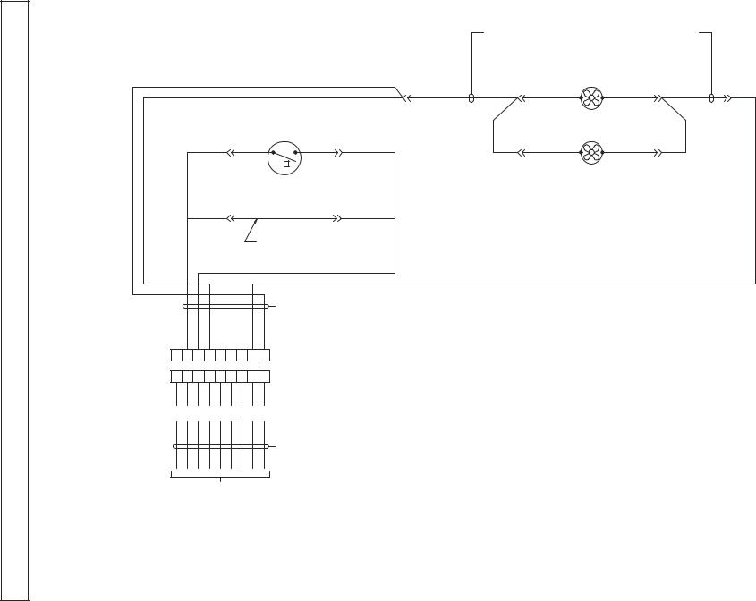
DIAGRAM WIRING
29
|
|
|
|
|
HARNESSEVAPORATOR FAN EXTENSION |
|
|||
|
|
|
|
|
GROUP -01; 1 DOOR |
|
|
|
|
|
|
|
|
|
GROUP -02; 2 DOOR/3 DOOR |
|
|
||
|
|
|
BK |
|
|
EVAP FAN/S |
|
|
|
|
|
|
|
|
|
|
|
|
|
|
|
|
BN |
BN |
BN |
BK |
BK |
WE |
WE |
|
EVAPORATOR AREA |
|
|
|
1 FAN |
|
|
|
|
|
MOUNTED |
|
|
|
|
|
|
||
|
|
|
|
|
|
|
|
||
|
CAVITY T'STAT |
|
|
|
|
|
|
|
|
OE |
SPADE |
SPADE |
OE |
|
BN |
BK |
BK |
WE |
|
|
|
|
|
|
|
2 FANS |
|
|
|
|
|
|
|
USE WITH |
|
|
|
|
|
OE |
|
OE |
OE |
REMOTE |
|
|
|
|
|
|
MOUNTED |
|
|
|
|
|
|||
CAVITY
T' STAT
(REMOVE JUMPER WHEN
INSTALLING THERMOSTAT)
HARNESSEVAPORATOR AREA
GROUP -02
OE OE BN |
|
|
WE BK |
|||||
1 |
2 |
3 |
4 |
5 |
6 |
7 |
8 |
9 |
1 |
2 |
3 |
4 |
5 |
6 |
7 |
8 |
9 |
YW |
OE |
PE |
BN |
BE |
RD |
GY |
WE |
BK |
HARNESSMAIN CABINET (EXIT EVAPORATOR AREA)
TO ELECTRICAL BOX
*GR.-01
MED. TEMP MODELS
*-0050-00 – DIAGRAM WIRING EVAPORATOR
 Loading...