


8HR
CARRIER COMMERCIAL REFRIGERATION, INC.
Providing BEVERAGE-AIR • FRIGIDAIRE • KELVINATOR • UNIVERSAL NOLIN Products/Services
SERVICE &
INSTALLATION
MANUAL
DIPPING
CABINETS
R-404A Refrigerant
1 / 2003
51-1298-02
If additional information is necessary, call Carrier Refrigeraiton
Operations headquarters.
Our toll free number is 1-800-684-1199.Technical assistance engineers are
willing to assist you in any way possible. Office hours are from 8:00 a.m. to
5:30 p.m., Eastern Standard Time.
Important information is contained in this manual which should
be retained in a convenient location for future reference.
Information in this manual is subject to change without notice.
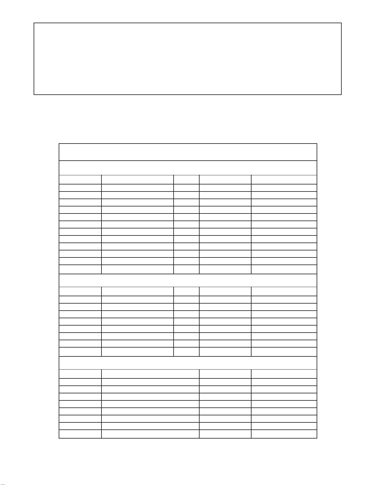
MODEL DESIGNATION INFORMATION
115V, 60HZ
PAR T # MODEL # DATA PLATE STYLE
52-1802-31 CKDC27 4HC CURVED
52-1802-32 CKDC47 8HC CURVED
52-1953-31 CKDC47 3500K LIGHTS 8HC CURVED
52-1802-33 CKDC67 12HC CURVED
52-1953-33 CKDC67 3500K LIGHTS 12HC CURVED
52-1802-34 CKDC87 16HC CURVED
52-1953-32 CKDC87 3500K LIGHTS 16HC CURVED
52-1802-35 KDC27 DL4C 4HR/4HJ STRAIGHT
52-1802-36 KDC47 DL8C 8HR/8HJ STRAIGHT
52-1963-31 KDC47F SS NO LIGHTS 8HF STRAIGHT
52-1802-37 KDC67 DL12C 12HR STRAIGHT
52-1802-38 KDC87 DL16C 16HR STRAIGHT
EXPORT 220V, 50HZ
PAR T # MODEL # DATA PLATE STYLE
52-1901-35 ECKDC27 E4HC CURVED
52-1901-36 ECKDC47 E8HC CURVED
52-1901-31 ECKDC67 ECKDC-67 CURVED
52-1901-32 ECKDC87 ECKDC-87 CURVED
52-1901-37 EKDC27 EDL4C E4HR STRAIGHT
52-1901-38 EKDC47 EDL8C E8HR STRAIGHT
52-1901-33 EKDC67 EDL12C EKDC-67 STRAIGHT
52-1901-34 EKDC87 EDL16C EKDC-87 STRAIGHT
EXPORT 220V, 60HZ
PAR T # MODEL # DATA PLATE STYLE
52-1944-35 KCKDC27 E4HC2 CURVED
52-1944-36 KCKDC47 E8HC2 CURVED
52-1944-31 KCKDC67 E12HC2 CURVED
52-1944-32 KCKDC87 E16HC2 CURVED
52-1944-37 KKDC27 E4HR2 STRAIGHT
52-1944-38 KKDC47 E8HR2 STRAIGHT
52-1944-33 KKDC67 E12HR2 STRAIGHT
52-1944-34 KKDC87 E16HR2 STRAIGHT
Manual effective for models produced January, 2003. Starting serial number 6527372.
Introduction
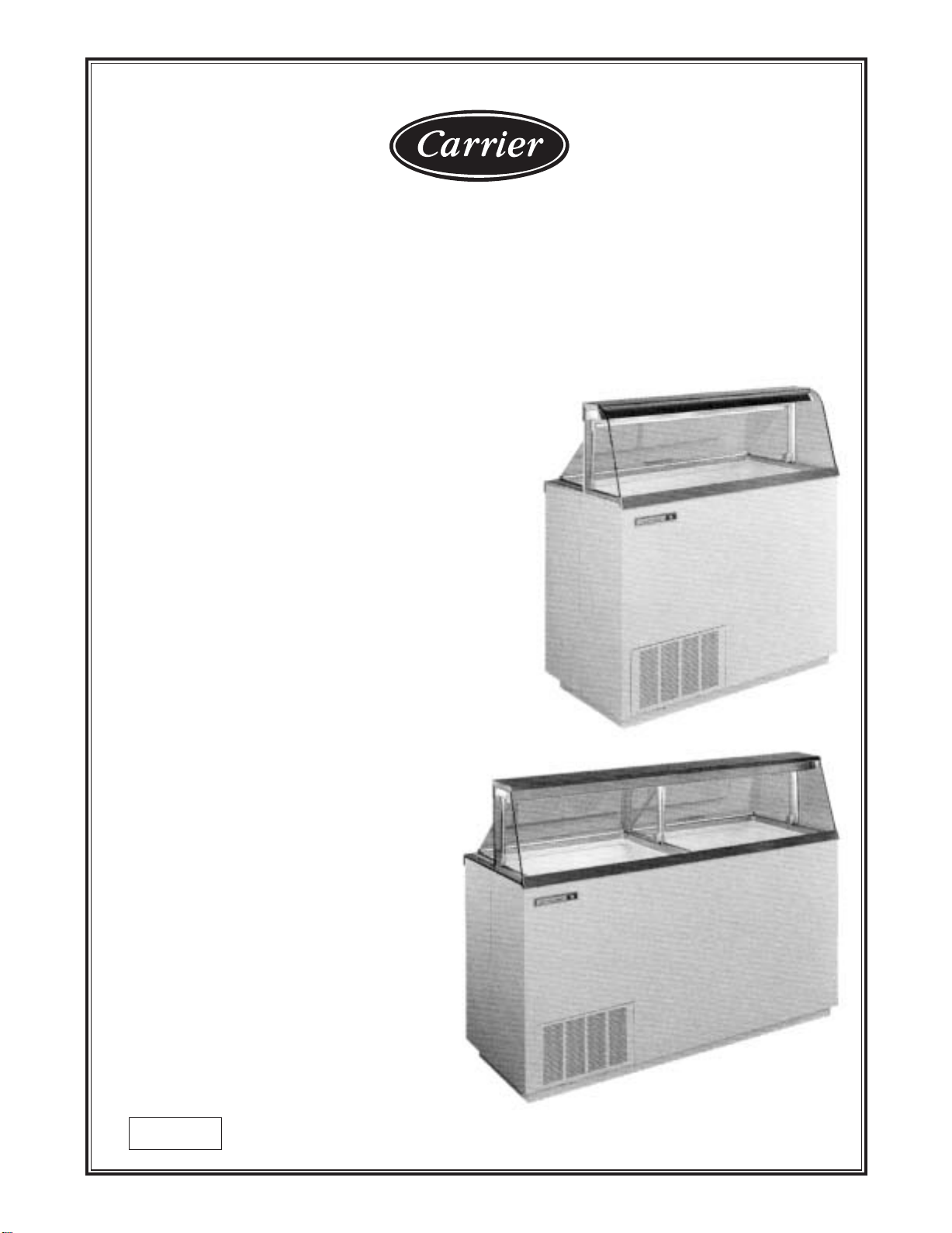
Dipping Cabinet Introduction
These Dipping Cabinets are designed to merchandise ice cream or yogurt type
products. Dipping cabinets are produced in four sizes: 4, 8, 12, and 16 facings
of ice cream containers. The cabinet systems contain R-404A refrigerant,
metered into the system by a capillary tube. The evaporator is a cold wall which
has the refrigerant lines strapped to the inner liner of the cabinet. The condenser
is a bare tube mounted on a pullout machinery compartment tray for ease of
servicing. All electrical controls are easily accessible for repair. The temperature
within the cavity is controlled thermostatically, allowing for maintenance of
correct dipping temperatures.
Mechanical equipment may require repair at times. This manual presents
information that is helpful in maintaining, diagnosing, and repairing these
cabinets.
The high level of quality built into these units will allow for many years of
trouble free operation.
2 INTRODUCTION

TABLE OF CONTENTS
INTRODUCTION
Introduction ........................................................................ 2
Table of Contents ................................................................3
CABINET SPECIFICATIONS/DIMENSIONAL DRAWINGS
4HR & 4 HC & EXPORT .................................................. 4
8HR & 8HC & EXPORT .................................................. 5
12HR & 12HC & EXPORT .............................................. 6
16HR & 16HC & EXPORT .............................................. 7
Handling & Installation ...................................................... 8
Product Load Line Location .............................................. 10
PRINCIPLES OF OPERATION
General Operations Information ........................................ 13
4HR & 4HC Electrical & Refrigeration Specs .................... 14
8HR & 8HC Electrical & Refrigeration Specs .................... 15
12HR & 12HC Electrical & Refrigeration Specs ................ 16
16HR & 16HC Electrical & Refrigeration Specs ................ 17
E4HR & E4HC Electrical & Refrigeration Specs. .............. 18
(220V / 60 Hz)
E8HR & E8HC Electrical & Refrigeration Specs. .............. 19
(220V / 60 Hz)
E12HR & E12HC Electrical & Refrigeration Specs. .......... 20
(220V / 60 Hz)
E16HR & E16HC Electrical & Refrigeration Specs. .......... 21
(220V / 60 Hz)
4HR, 4HC / 8HR, 8HC / E4HR, E4HC / E8HR, E8HC
Wiring Diagram ................................................................ 22
12HR, 12HC / 16HR, 16HC Wiring Diagram .................... 23
Condenser Fan Motor Replacement .................................. 44
Ballast Replacement ........................................................ 45
Metering Device / Heat Exchanger Replacement .............. 46
Cabinet Troubleshooting Guide ........................................ 47
Compressor Troubleshooting Guide ................................ 49
Fluorescent Lamp Troubleshooting Guide ........................ 50
Measurements - Starting Lamp Voltage .......................... 52
ILLUSTRATIONS & PARTS
Cabinet Parts - Exploded View .......................................... 54
Cabinet Parts List ............................................................ 55
Canopy Parts - Exploded View .......................................... 56
Canopy Parts List ............................................................ 57
Condensing Unit - Exploded View .................................... 58
Condensing Unit Parts List .............................................. 59
Electrical Components - Exploded View .......................... 60
Electrical Components Parts List ...................................... 61
Lid - Exploded View .......................................................... 62
Lid Parts List .................................................................... 63
ACCESSORIES
Can Skirt Accessory Parts List ........................................ 67
Can Skirt Installation ........................................................ 68
Dipperwell Installation ...................................................... 70
Sanitary Base Leg Installation .......................................... 71
Caster Installation ............................................................ 72
Lid Lock Kit Installation .................................................... 73
Can Clamp Installation ...................................................... 74
Round Can Clamp Installation .......................................... 75
Half-way Shelf Bottom Support Kit Installation ................ 76
ECKDC67, EKDC67 / ECKDC87, EKDC87
E12HC2, E12HR2 / E16HC2, E16HR2
WIRING DIAGRAM..............................................................24
8HC, 12HC, 16HC (3500K LIGHTS)
WIRING DIAGRAM..............................................................25
MAINTENANCE & REPAIR
Pre-Service Check List ...................................................... 29
General Maintenance Information .................................... 30
Compressor Installation / Diagnostics .............................. 32
Cleaning & Maintenance .................................................. 34
Cleaning the Lid & Touch-up Painting .............................. 35
Lid Seal Replacement ...................................................... 36
Lid Gasket Replacement .................................................. 37
Lid Pivot Bushing Assembly Replacement ...................... 38
Center & End Pivot Rod Replacement .............................. 39
Fluorescent Lamp Holder/Light Starter Socket Replac. .... 40
Fluorescent Bulb & Starter Replacement .......................... 41
Thermostat Replacement .................................................. 42
Master Power Supply Switch / Light Switch Removal ...... 43
Specifications are subject to change without notice.
TABLE OF CONTENTS 3
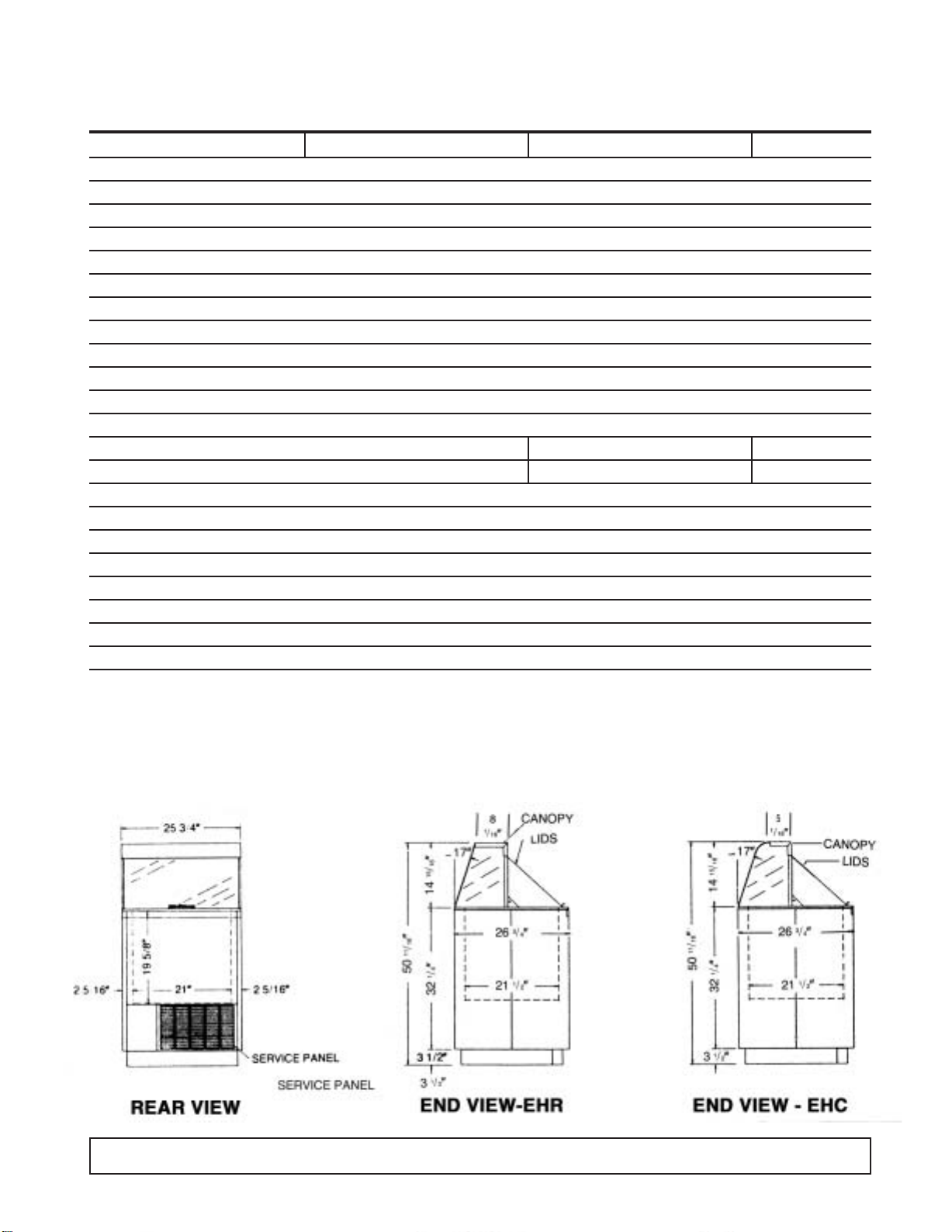
CABINET SPECIFICATIONS
4HC & 4HR/4HJ E4HC & E4HR E4HC2 & E4HR2
Temp. Range +10°F to -8°F
Capacity 4.6 Cu. Ft.
Capacity (3 Gal. Tubs) 4
Facings (3 Gal. Tubs) 4
Storage (3 Gal. Tubs) 0
Compressor Size 1/4 Hp.
Shipping Weight (App.) 235 lbs.
Condenser Type Bare Tube
Evaporator Type Cold Wall
Refrigerant R-404A
Refrigerant Control Capillary Tube
Defrost System Manual
Rated Amps 3.0 1.7 1.7
Electrical Specs. 115V, 60 Hz., 1 Ph. 220V, 50 Hz., 1Ph 220V, 60 Hz., 1 Ph.
Power Cord No. 16AWG
NSF Listing NSF7
Canopy Construction S.S. Top with Glass ends Straight or Curved Front Glass
Lids (Plexiglass) 1 Lid
Interior Finish White Baked Enamel on Galvanized Steel
Exterior Finish White Baked Enamel
Lighting One 20 Watt Bulb
Accessories Can Skirt Kit, Lid Locks, Dipperwell, Night Covers, Casters, Legs
DIMENSIONAL DATA
4 INTRODUCTION
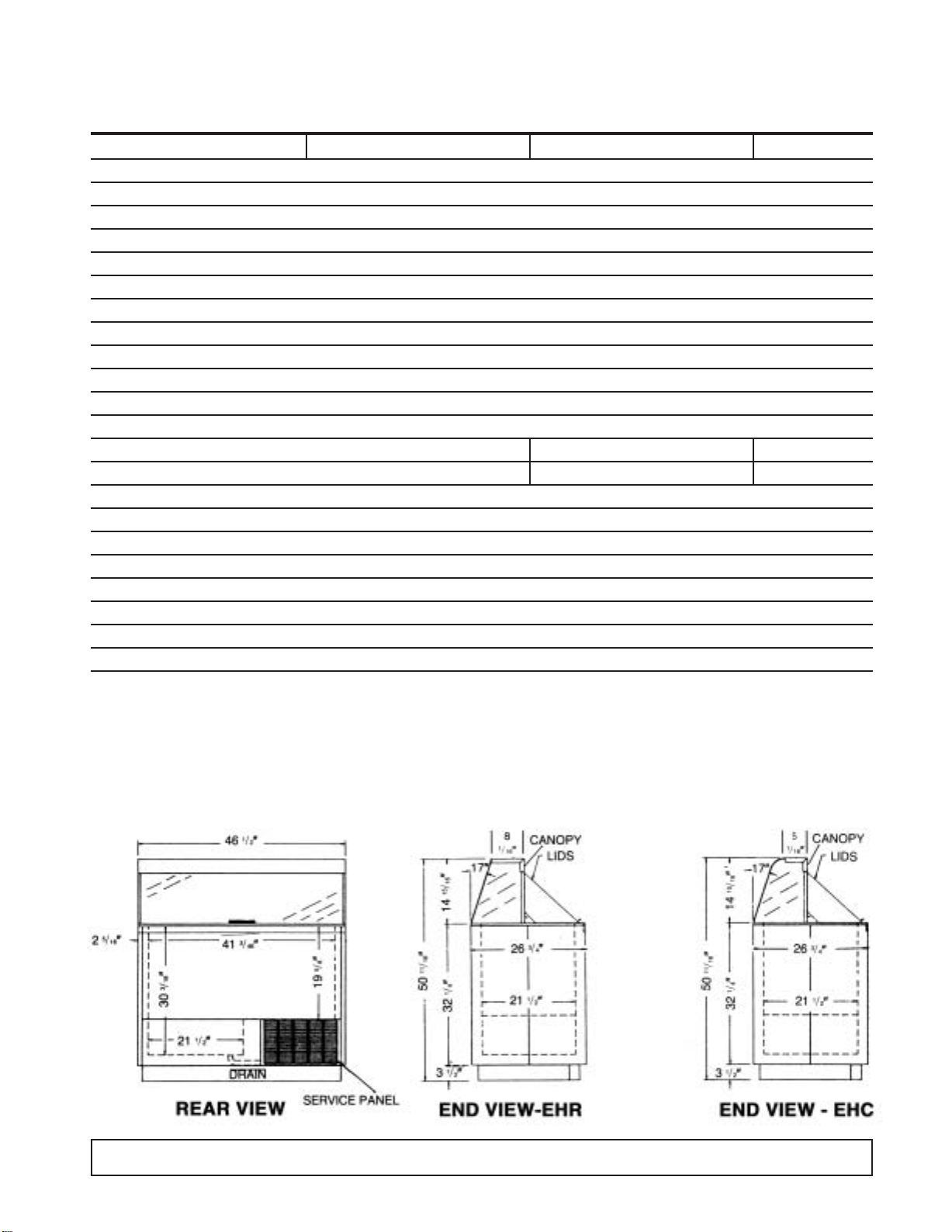
CABINET SPECIFICATIONS
8HC & 8HR/8HJ & 8HF E8HC & E8HR E8HC2 & E8HR2
Temp. Range +10°F to -8°F
Capacity 12.0 Cu. Ft.
Capacity (3 Gal. Tubs) 12
Facings (3 Gal. Tubs) 8
Storage (3 Gal. Tubs) 4
Compressor Size 1/3 Hp.
Shipping Weight (App.) 365 lbs.
Condenser Type Bare Tube
Evaporator Type Cold Wall
Refrigerant R-404A
Refrigerant Control Capillary Tube
Defrost System Manual
Rated Amps 4.0 2.1 2.1
Electrical Specs. 115V, 60 Hz., 1 Ph. 220V, 50 Hz., 1 Ph. 220V, 60 Hz., 1Ph.
Power Cord No. 16AWG
NSF Listing NSF7
Canopy Construction S.S. Top with Glass ends Straight or Curved Front Glass
Lids (Plexiglass) 1 Lid
Interior Finish White Baked Enamel on Galvanized Steel
Exterior Finish White Baked Enamel
Lighting Two 20 Watt Bulbs Standard (17 Watt Bulbs on Special Cabinets with 3500 K Lighting)
Accessories Can Skirt Kit, Lid Locks, Dipperwell, Night Covers, Casters, Legs
DIMENSIONAL DATA
INTRODUCTION 5
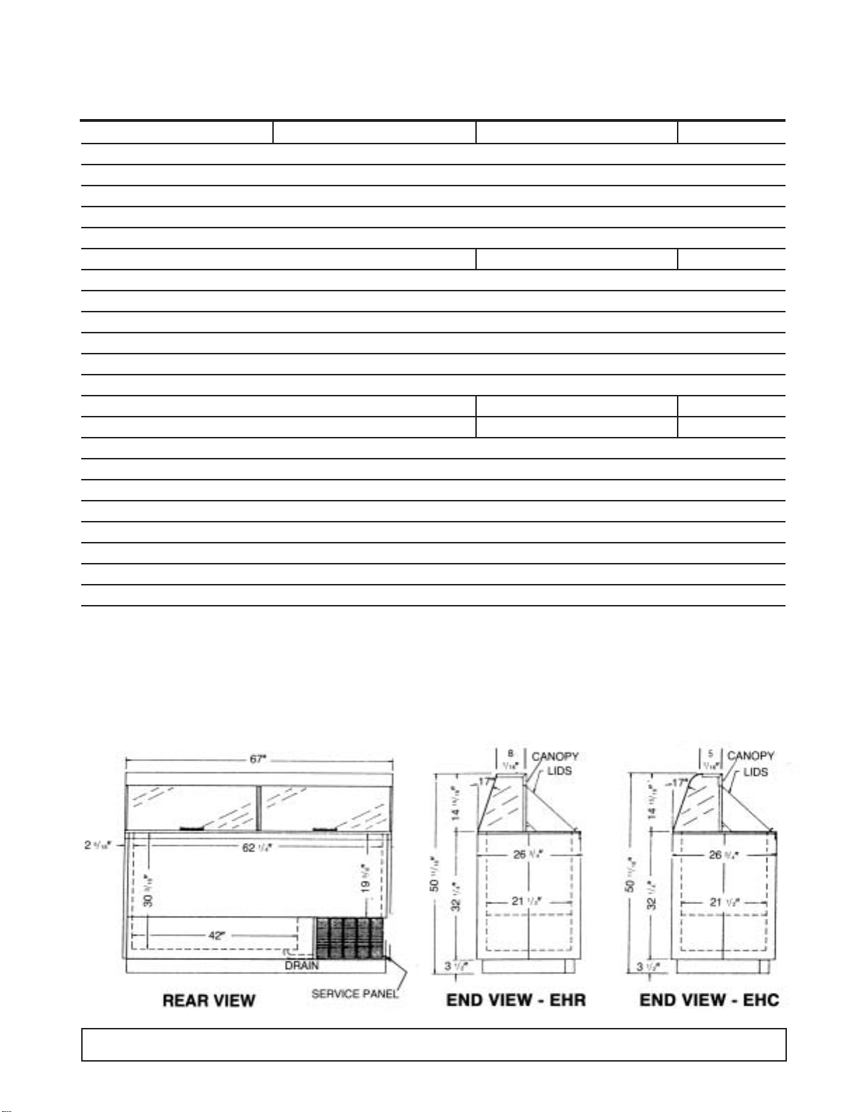
CABINET SPECIFICATIONS
12HC & 12HR ECKDC-67 & EKDC-67 E12HC2 & E12HR2
Temp. Range +10°F to -8°F
Capacity 19.1 Cu. Ft.
Capacity (3 Gal. Tubs) 20
Facings (3 Gal. Tubs) 12
Storage (3 Gal. Tubs) 8
Compressor Size 1/3 Hp. 3/4 Hp. 3/4 Hp.
Shipping Weight (App.) 525 lbs.
Condenser Type Bare Tube
Evaporator Type Cold Wall
Refrigerant R-404A
Refrigerant Control Capillary Tube
Defrost System Manual
Rated Amps 8.0 4.1 4.1
Electrical Specs. 115V., 60 Hz, 1 Ph. 220V, 50 Hz, 1 Ph. 220V, 60 Hz, 1 Ph.
Power Cord Yes
NSF Listing NSF7
Canopy Construction S.S. Top with Glass ends Straight or Curved Front Glass
Lids (Plexiglass) 2 Lid
Interior Finish White Baked Enamel on Galvanized Steel
Exterior Finish White Baked Enamel
Lighting Two 30 Watt Bulbs Standard (32 Watt Bulbs on Special Cabinets with 3500 K Lighting)
Accessories Can Skirt Kit, Lid Locks, Dipperwell, Night Covers, Casters, Legs
DIMENSIONAL DATA
6 INTRODUCTION
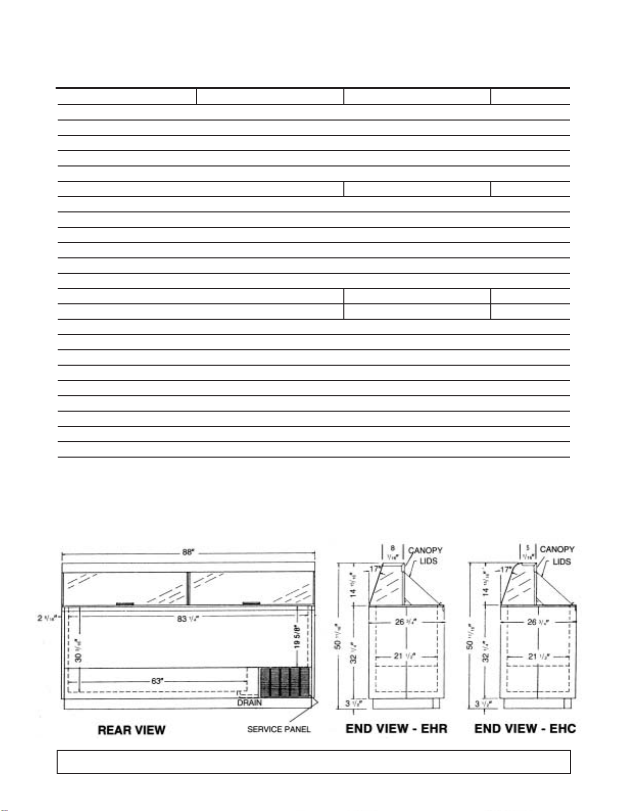
CABINET SPECIFICATIONS
16HC & 16HR ECKDC-87 & EKDC-87 E16HC2 & E16HR2
Temp. Range +10°F to -8°F
Capacity 19.1 Cu. Ft.
Capacity (3 Gal. Tubs) 20
Facings (3 Gal. Tubs) 12
Storage (3 Gal. Tubs) 8
Compressor Size 1/3 Hp. 3/4 Hp. 3/4 Hp.
Shipping Weight (App.) 525 lbs.
Condenser Type Bare Tube
Evaporator Type Cold Wall
Refrigerant R-404A
Refrigerant Control Capillary Tube
Defrost System Manual
Rated Amps 8.0 4.1 4.1
Electrical Specs. 115V, 60 Hz., 1 Ph. 220V, 50 Hz, 1 Ph. 220V, 60 Hz, 1 Ph.
Power Cord Yes
NSF Listing NSF7
Canopy Construction S.S. Top with Glass ends Straight or Curved Front Glass
Lids (Plexiglass) 2 Lid
Interior Finish White Baked Enamel on Galvanized Steel
Exterior Finish White Baked Enamel
Lighting Two 40 Watt Bulbs Standard (32 Watt Bulbs on Special Cabinets with 3500 K Lighting)
Accessories Can Skirt Kit, Lid Locks, Dipperwell, Night Covers, Casters, Legs
DIMENSIONAL DATA
INTRODUCTION 7
HANDLING & INSTALLATION-Illuminated Dipping Cabinets
FREIGHT DAMAGES AND SHORTAGES
IMPORTANT
The cabinet was inspected and packaged at the
factory, and should have arrived in excellent
condition. The transportation company or other
parties involved in the shipment are responsible for
loss and/or “damage.” Always make an inspection
before and after uncrating, pref erab ly at the point of
unloading by the transportation company.
INSPECTING FOR DAMAGES
Note:
Always use care when removing shipping tape,
blocks, pads, hardware or other material. Contact
your dealer or distributor if technical assistance
is required.
Check the cartons or containers. If these are damaged
in any way, open them and inspect the contents in the
driver’s presence. If damage is detected, do the
following:
1. Have the driver note the nature and extent of the
damage on the freight bill.
2. Notify the transpor tation company’s office to request
an inspection. Carrier claim policies usually require
inspections to be made within 15 days of delivery.
3. If damage is noticed, file a claim with the
transportation company.
FILING A CLAIM
File a claim for loss at once with the transportation
company for:
A. A cash adjustment B. Repairs C. Replacement
When filing your claim, retain all packaging materials
and receipts.
HANDLING THE CABINET
Note:
The refrigeration system of the cabinet is designed
to operate with the cabinet located on a flat surface.
Do not tilt the cabinet more than 30° to any side. If
the cabinet must be tilted on an angle for handling or
moving purposes, allow it to sit in an upright position
20 to 30 minutes prior to operating.
CHOOSE A LOCATION
This model cabinet should be situated to allow proper air
circulation. The cabinet must be installed on sturdy, level
floor and positioned so that it can be plugged into a
properly grounded three-prong electrical wall outlet. The
electrical outlet should not be controlled by a wall switch
which might be turned off accidentally.
UNCRATING THE CABINET
The cabinet should be moved as close as possible to
the operating location before removing the skid. Be
sure to follow the steps in the “INSPECTING FOR
DAMAGES” instructions.
INSTALLING THE CABINET
Whenever possible leave the crate skid on the cabinet
until it is moved close to the final position. When it is
necessary to move the cabinet through a doorway, it
may be necessary to remove the crate skid.
Run the cabinet down to storage temperature before
adding product.
CAUTION
A. Do not locate cabinet where sunlight or drafts from
fans, air conditioners or open doors can affect product
temperature.
B. Run cabinet before building in or attaching panels or
accessories.
C. Employee side access panel must be kept clear for
adjustments and service.
D. Cabinet must be installed on the finished floor to
assure rear raceway cover and condensing unit
(employee side) can be pulled or removed for service.
DO NOT seal in with cover molding or caulking in the
area where condensing unit pulls out.
E. Do not use extension cords to power this equipment.
Run any necessary electrical, water supply and drain
lines before setting the cabinet in position. Shim under
the cabinet as necessary to level it. N.S.F. approval
requires sealing the cabinet to the floor. This can be
done by applying a bead of mastic sealer between the
cabinet bottom flange and the floor.
Should several cabinets be set up in a row, space is
provided in the rear toe space for routing electrical and
plumbing lines.Access to this space requires removing
screws and the metal cover which runs the length of the
cabinet.
Rivnuts are provided on the operator's side for
mounting dipperwell and other accessories.
CABINET START-UP
Once the cabinet has been located in its permanent
location and the proper power and grounding have
been provided, the following items must be checked or
completed:
A. Cut and remove the compressor hold-down band (if
applicable) so the compressor “floats” freely.
8 INTRODUCTION
B. Check for traces of oil on the compressor pan which
could mean a broken or leaking refrigeration line.
UNDER NO CIRCUMSTANCE SHOULD THE
COMPRESSOR BE STARTED WHEN OIL IS
PRESENT UNTIL INSPECTED BY A SERVICE
TECHNICIAN.
C. INSPECT THE FACTORY WIRING FOR
TERMINALS THAT MIGHT HAVE VIBRATED
LOOSE IN SHIPPING. TIGHTEN ALL SCREW
TYPE TERMINALS.
D. Check the refrigeration lines to see that they are
“free” and no damage was done during shipping.
E. Check fan blade for free operation.
F. Turn on the main power switch.Once the compressor
starts, the voltage should be checked at the
compressor terminals to determine if there is proper
voltage to the compressor. The voltage should not
exceed the 10% above or below the rated
compressor voltage.
EXAMPLE: If the voltage reads 220 volts with no load
and it drops below 210 volts when the compressor
starts, it may indicate that the supply wiring is too small
or that the wire run is too long.
G. Listen for any unusual noise such as lines vibrating,
etc. Correct the problem by tightening screws,
slightly bending tubing, etc.
H.The temperature control thermostat which is located
in the rear post is factory set for average conditions.
A customer adjustment requires a coin or
screwdriver to turn the slotted shaft.A numbered dial
makes it easy to keep track of adjustments. #1 is
warmest setting and #7 is coldest setting. An “OFF”
position is provided for your convenience in
defrosting the cabinet.
I. Allow the cabinet to pull down and cycle prior to
loading with product (Approx. 24 hours).
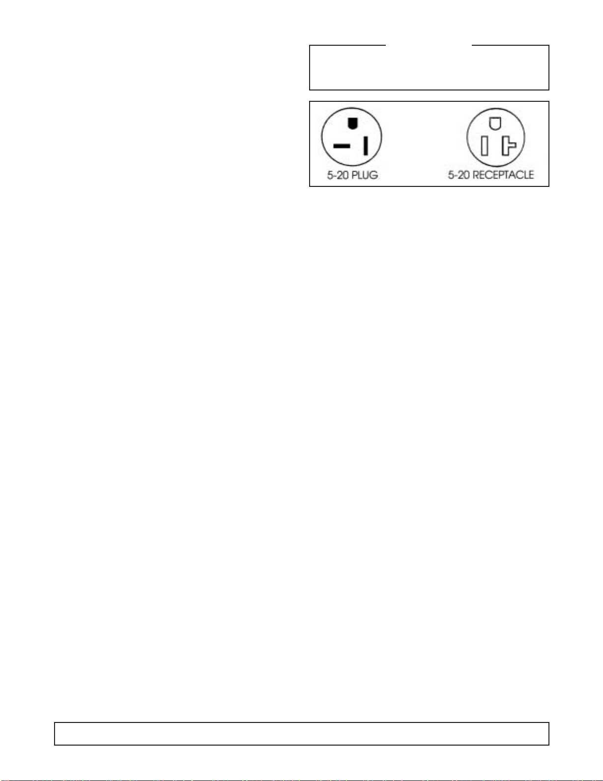
GROUNDING INSTRUCTIONS
This appliance is equipped with a three-prong
(grounding) plug for your protection against shock
hazards.The appliance should be plugged directly into
a properly grounded three-prong receptacle.
Where a two-prong wall receptacle is encountered, it
must be replaced with a properly grounded three-prong
receptacle in accordance with the National Electrical
Code and local codes and ordinances. The work must
be done by a licensed electrician.
IMPORTANT
Do not, under any circumstance, cut or remove the
round grounding plug from the appliance plug.
WARNING
Consult a licensed electrician if you have any doubt
about the grounding of your wall receptacle. Only a
licensed electrician can determine the polarization of
your wall receptacle. Only a properly installed threepronged wall receptacle assures the proper
polarization with the appliance plug.
IMPORTANT USAGE INSTRUCTIONS
Dipping Cabinet
The cabinet must be located in an area free from air
drafts created by open doors, air conditioning ducts,
and fans. The cabinet should not be located in the
direct sunlight.
The rear grill must be clear of any obstructions so the
intake and exhausting of air f or the condensing unit can
move freely.
Dipping cabinets are designed for use in an air
conditioned store. This cabinet is designed for
merchandising, not hardening of the product.
High humidity can cause fogging of the lid and front glass.
High temperatures, installation of warm product and
heavy usage can cause the product to soften. This
condition will be more noticeable at the top of the cans.
The corners of the cabinets are the coldest areas.
These areas should be used for product that is more
difficult to keep firm.
Frost and ice act as insulators. The need for defrosting
will depend on usage and product firmness.
If the frost is scraped daily with a plastic scraper,
intervals between complete defrosting may be
extended.
Thermostat adjustments should be made one
increment warmer or colder allowing 24 hours between
adjustments to allow the product to stabilize.
INTRODUCTION 9
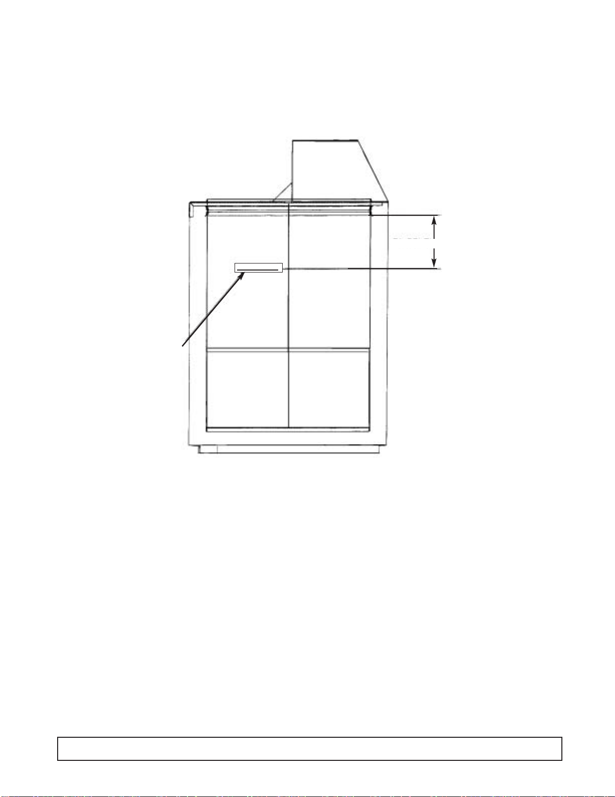
PRODUCT LOAD LINE LOCATION
KEEP PRODUCT BELOW RED LINE
7" BELOW BREAKER
NOTE:
KEEP PRODUCT
BELOW THIS LINE.
10 INTRODUCTION
SECTION II
Principles of
Operation

blank
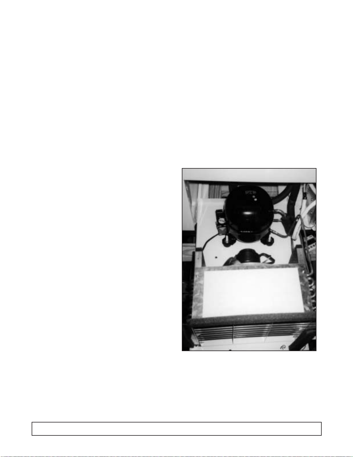
GENERAL OPERATIONS
All the dipping cabinet models are of the same basic
design, consisting of a bare tube condenser and a cap
tube fed tank wrap evaporator.
Ice formation on the walls over a period of time is
normal. This frost should be scraped off periodically in
order to maintain peak performance. These cabinets
are thermostatically controlled for various temperature
requirements.The thermostat is located post adjacent
to the unit compartment and can be accessed for
adjustment by the user with a screwdriver or a dime.
Thermostat position #1 being the warmest and
position #7 the coldest.
These cabinets are manual defrost and a drain is
provided for periodic cleaning. A garden hose can be
attached to the drain plug for draining away any water
that might have accumulated.This drain attachment is
located in the front base rail of the cabinet.NOTE:The
power supply cord must be disconnected when
cleaning or servicing these cabinets.
NOTE: On initial cabinet pull down the bare tube
condenser may become warm to the touch until
the normal operating temperatures are achieved.
Compressors being used in these cabinets utilize
refrigerant 404A and polyol ester oil. Because of the
hygroscopic nature of this oil, extreme care must be
taken when any component is changed within the
system. In the case of compressor replacement, work
should be completed before the caps are removed
from the compressor.
Agitation of the oil should be kept to a minimum.
Compressors should not be open to the atmosphere
for more than 15 minutes max. Should contamination
occur the oil can be removed and recharged (following
compressor manufacturer's guidelines when
performing this procedure). Because of the porous
nature of plastic, polyol ester oil should be stored in a
metal container. Moisture contained within the oil
cannot be removed even under high vacuum
conditions and must be replaced.
Refer to model serial data tag for cabinet amperage,
refrigerant charge & type.
PRINCIPLES OF OPERATION 13
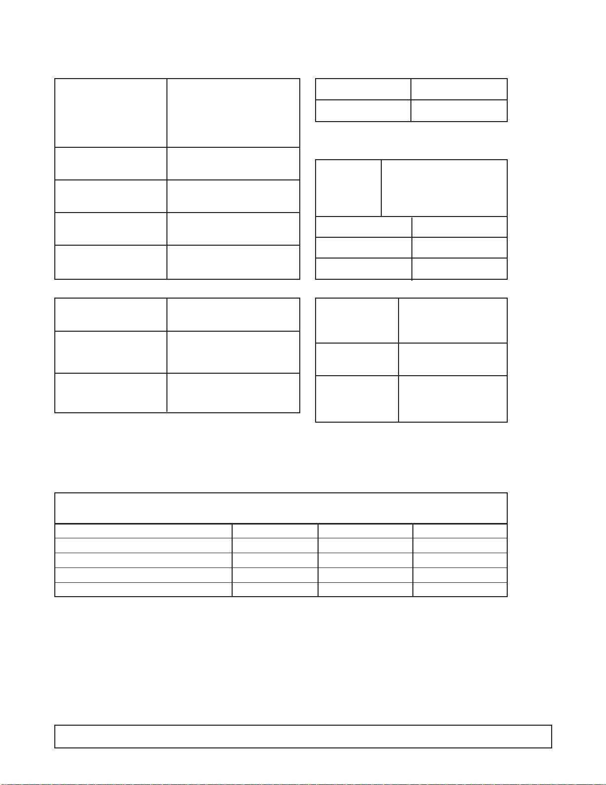
SYSTEM INFORMATION - 4HR & 4HC
ELECTRICAL
Compressor Manufacturer: Americold
Model: HP-110-3083
V.: 115/100 R.L.A.: 2.0
L.R.A.: 10 Phase 1
Overload Protector Americold #1456-3453
Start Relay T.I.: Americold #1456-3372
Start Capacitor V.A.C.: 165 M.F.: 88-108
Run Capacitor V.A.C.: 180 M.F.: 15
Condenser Manufacturer: Heatcraft
Condenser Manufacturer: G.E.
Fan Motor Model:5KSM51GG-37845
Evaporator Cold Wall
Capillary Tube 7' of .031
Thermostat Manufacturer: Ranco
F.L.A.: 25
V.: 120/240 L.R.A.: 100
Warm C ut-in 11° Warm Cut-out —
Mid Cut-in -12° Mid Cut-out -24°
Cold Cut-in — Cold Cut-out -34°
Pow er Cord A.W.G.: 14
A.: 15 @ 125V
Light Ballast Manufacturer: G.E.
Model: 89G457
Condenser Diameter: 8" # of Blades: 3
Fan Blade Width of Blades:1 7/8"
REFRIGERATION -
Refrig. Charge: R-404A / 11.5 oz. / 326.02 grams / No.4 Stat Position
Fluorescent Manufacturer: G.E.
Lamp F20T12 CW
AMBIENT TEMPERATURE 70°F / 21.1°C 80°F / 27°C 90°F / 32.5°C
CONTROL SETTINGS #4 C.S. #4 C.S. #4 C.S.
Suction Pressure - C.O. PSIG/Kpa 13 / 13 / 14 /
Discharge Pressure - C.O. PSIG/Kpa 196 / 224 / 246 /
Compressor Amps 1.8 1.8 1.8
Total Cabinet Amps 2.3 2.0 2.0
Cavity Temperature C.L. 0°F / -17°C 2°F / -16°C 3°F / -16°C
14 PRINCIPLES OF OPERATION
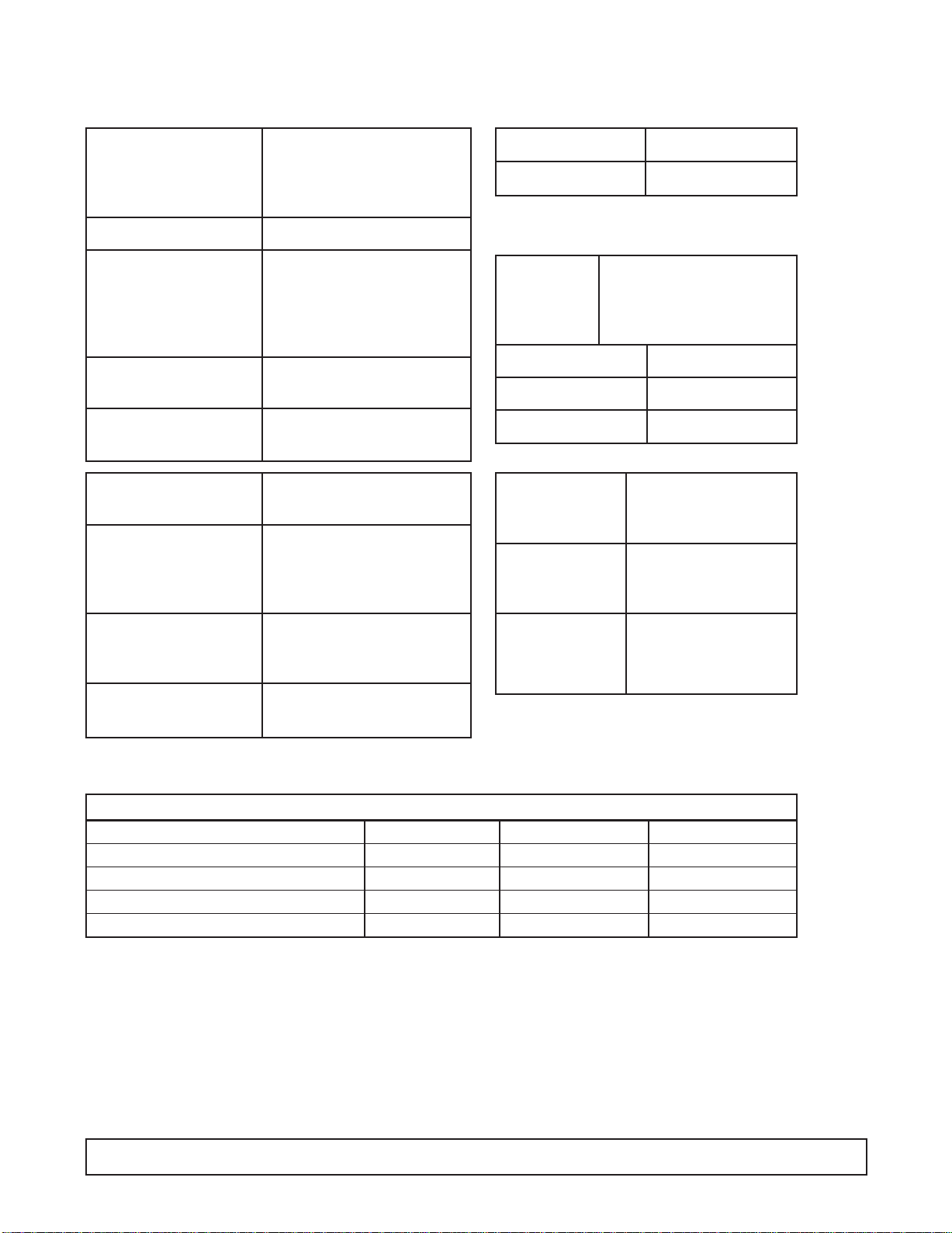
SYSTEM INFORMATION - 8HR & 8 HC
ELECTRICAL
Compressor Manufacturer: Americold
Model: HP-117-1
V.: 115/100 R.L.A.: 3.0
L.R.A.: 21.4 Ph.: 1 HP:
Overload Protector Americold #1456-3454
Start Relay T.I.: 8EA1206K1A
Start Capacitor V.A.C.: 165 M.F.: 88-108
Run Capacitor V.A.C.: 200 M.F.: 15
Condenser Manufacturer: Heatcraft
Condenser Manufacturer: Morrill
Fan Motor Model:SPB9S1
Condenser Diameter: 8" # of Blades: 3
Fan Blade Width of Blades:2 3/4"
1
⁄3
Evaporator Cold Wall
Capillary Tube 8' of .036
Thermostat Manufacturer: Ranco
F.L.A.: 25
V.: 120/240 L.R.A.: 100
Warm C ut-in 11° Warm Cut-out —
Mid Cut-in -12° Mid Cut-out -24°
Cold Cut-in — Cold Cut-out -34°
Pow er Cord A.W.G.: 14
A.: 15 V.: 125
Light Ballast Manufacturer: G.E.
Model: 89G457(STD)
B232I120RH (3500K)
Fluorescent Manufacturer: G.E.
Lamp F20T12 CW (STD)
F17T8 / SP35 (3500K)
REFRIGERATION -
Refrig. Charge: R-404A / 17 oz. / 481.95 grams / No.4 Stat Position
AMBIENT TEMPERATURE 70°F / 21.1°C 80°F / 27°C 90°F / 32.5°C
CONTROL SETTINGS #4 C.S. #4 C.S. #4 C.S.
Suction Pressure - C.O. PSIG/Kpa 9 / 12 / 13 /
Discharge Pressure - C.O. PSIG/Kpa 187 / 228 / 251 /
Compressor Amps 2.9 2.9 2.9
Total Cabinet Amps 3.5 3.5 3.5
Cavity Temperature C.L. 5°F / -15°C 7°F / -13°C 8°F / -13°C
PRINCIPLES OF OPERATION 15

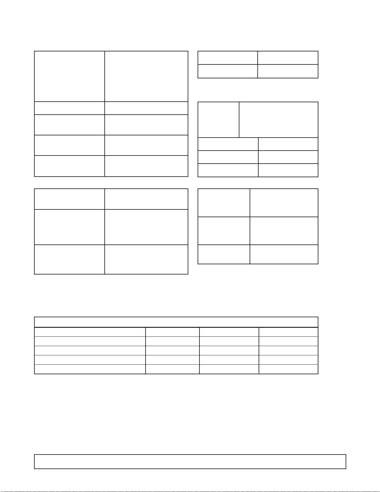
SYSTEM INFORMATION - 12HR & 12HC
ELECTRICAL
Compressor Manufacturer: Americold
Model: HP-127-1
Ph.: 1 Hz.: 60
Volts: 115 Amps: 4.2
Overload Protector Manufacturer: Amer icold
Start Relay Manufacturer: Americold
Start Capacitor V.:125 M.F.: 189-227
Run Capacitor VAC: 370 M.F.: 20
Condenser Manufacturer: Heatcraft
Condenser Manufacturer: G.E.
Fan Motor Model:5KSM51GG3784
Condenser Diameter: 9.5" # Blades: 3
Fan Blade Width of Blades:1 29/32"
Evaporator Cold Wall
Capillary Tube 7' of .042
Thermostat Manufacturer: Ranco
F.L.A.: 25
V.: 120/250 L.R.A.: 100
Warm C ut-in 11° Warm Cut-out —
Mid Cut-in -12° Mid Cut-out -24°
Cold Cut-in — Cold Cut-out -34°
Pow er Cord A.W.G.: 16
A.: 15 V.: 125
Light Ballast Manufacturer: G.E.
Model: 89G457(STD)
B232I120RH(3500K)
Fluorescent Manufacturer: G.E.
Lamp F40T12CW (STD)
F32T8/SP35 (3500K)
REFRIGERATION -
Refrig. Charge: R-404A / 25 oz. / 708.75 grams / No.4 Stat Position
AMBIENT TEMPERATURE 70°F / 21.1°C 80°F / 27°C 90°F / 32.5°C
CONTROL SETTINGS #4 C.S. #4 C.S. #4 C.S.
Suction Pressure - C.O. PSIG/Kpa 9 / 10 / 11 /
Discharge Pressure - C.O. PSIG/Kpa 198 / 230 / 268 /
Compressor Amps 4.2 4.2 4.3
Total Cabinet Amps 6.1 6.1 6.2
Cavity Temperature 0°F / -17°C 1°F / -17°C 2°F / -16°C
16 PRINCIPLES OF OPERATION
SYSTEM INFORMATION - 16HR & 16HC
ELECTRICAL
Compressor Manufacturer: Americold
Model: HP-127-1
Volts: 115 R.L.A.: 4.2
L.R.A.: — Ph.: 1 Hz.: 60
Overload Protector Americold #1456-3321
Start Relay Americold #1456-3374
Start Capacitor V.:125 M.F.: 189-227
Run Capacitor V.: 370 M.F.: 20
Condenser Manufacturer: Heatcraft
Condenser Manufacturer: G.E.
Fan Motor Model:5KSM51GG3784
V.: 115 Hz.: 60 Ph.: 1
Evaporator Cold Wall
Capillary Tube 7' of .042
Thermostat Manufacturer: Ranco
F.L.A.: 25
V.: 120/240 L.R.A.: 100
Warm C ut-in 11° Warm Cut-out —
Mid Cut-in -12° Mid Cut-out -24°
Cold Cut-in — Cold Cut-out -34°
Pow er Cord A.W.G.: 16
A.: 15 V.: 125
Light Ballast Manufacturer: G.E.
Model: 8G3706 (STD)
B232I120RH (3500K)
Condenser Diameter: 9.5" # Blades: 3
Fan Blade Width of Blades:1 29/32"
REFRIGERATION -
Refrig. Charge: R-404A / 27 oz. / 765.45 grams / No.4 Stat Position
Fluorescent Manufacturer: G.E.
Lamp F40T12CW (STD)
F32T8/SP35 (3500K)
AMBIENT TEMPERATURE 70°F / 21.1°C 80°F / 27°C 90°F / 32.5°C
CONTROL SETTINGS #4 C.S. #4 C.S. #4 C.S.
Suction Pressure - C.O. PSIG/Kpa 9 / 10 / 12 /
Discharge Pressure - C.O. PSIG/Kpa 207 / 234 / 262 /
Compressor Amps 3.8 3.8 3.9
Total Cabinet Amps 6.3 6.3 6.3
Cavity Temperature C.L. -.5°F / -18°C -.3°F / -17.9°C -1.2°F / -18.4°C
PRINCIPLES OF OPERATION 17
SYSTEM INFORMATION - E4HR & E4HC (220V / 50 Hz)
ELECTRICAL E4HR2 & E4HC2 (220V / 60 Hz)
Compressor Manufacturer: Americold
Model: HP-110-12-3084
V.: 220 R.L.A.: 2.0
L.R.A.: 12.6 Phase: 1/50Hz.
Overload Protector T.I.: Americold #1456-3444
Start Relay T.I.: Americold #1456-3374
Start Capacitor V.A.C.: 250 M.F.: 108-130
Run Capacitor V.A.C.: 370 M.F.: 7.5
Condenser Manufacturer: Heatcraft
Condenser Manufacturer: G.E.
Fan Motor Model:5KSM51ECG3905
Evaporator Cold Wall
Capillary Tube 7' of .031
Thermostat Manufacturer: Ranco
F.L.A.: 25
V.: 120/240 L.R.A.: 100
Warm C ut-in 11° Warm Cut-out —
Mid Cut-in -12° Mid Cut-out -24°
Cold Cut-in — Cold Cut-out -34°
Pow er Cord A.W.G.: 14
A.: 15 @ 125V
Light Ballast Robertson #02025 (50Hz)
Robertson #02026 (60Hz)
Condenser Diameter: 8" # of Blades: 3
Fan Blade Width of Blades:1 7/8"
REFRIGERATION -
Refrig. Charge: R-404A / 11.5 oz. / 326.02 grams / No.4 Stat Position
Fluorescent Manufacturer: G.E.
Lamp F20T12/CW
AMBIENT TEMPERATURE 70°F / 21.1°C 80°F / 27°C 90°F / 32.5°C
CONTROL SETTINGS #4 C.S. #4 C.S. #4 C.S.
Cavity Temperature C.L. 0°F / -17°C 2°F / -16°C 3°F / -16°C
Suction Pressure - C.O. PSIG/Kpa 12 / 82 13 / 89 14 / 96
Discharge Pressure - C.O. PSIG/Kpa 206 / 1420 214 / 1475 239 / 1647
Compressor Amps 2.0 2.0 2.0
Total Cabinet Amps 2.3 2.3 2.3
18 PRINCIPLES OF OPERATION

SYSTEM INFORMATION - E8HR & E8HC (220V / 50 Hz)
ELECTRICAL E8HR2 & E8HC2 (220V / 60 Hz)
Compressor Manufacturer: Americold
Model: HP-118-12
V.: 220 R.L.A.: 3.0
L.R.A.: 12.6 Phase: 1/50Hz.
Overload Protector Americold #1456-3321
Start Relay T.I.: 8EA14
Start Capacitor V.A.C.: 250 M.F.: 108-130
Run Capacitor V.A.C.: 370 M.F.: 7.5
Condenser Manufacturer: Heatcraft
Condenser Manufacturer: G.E.
Fan Motor Model:5KSM51ECG3905
Evaporator Cold Wall
Capillary Tube 8' of .036
Thermostat Manufacturer: Ranco
F.L.A.: 25
V.: 120/240 L.R.A.: 100
Warm C ut-in 11° Warm Cut-out —
Mid Cut-in -12° Mid Cut-out -24°
Cold Cut-in — Cold Cut-out -34°
Pow er Cord A.W.G.: 14
A.: 15 @ 125V
Light Ballast Robertson #02026
Condenser Diameter: 8" # of Blades: 3
Fan Blade Width of Blades:1 7/8"
REFRIGERATION -
Refrig. Charge: R-404A / 17 oz. / 481.95 grams / No.4 Stat Position
Fluorescent Manufacturer: G.E.
Lamp F20T12/CW
AMBIENT TEMPERATURE 70°F / 21.1°C 80°F / 27°C 90°F / 32.5°C
CONTROL SETTINGS #4 C.S. #4 C.S. #4 C.S.
Cavity Temperature Range 5°F / -15°C 7°F / -13°C 8°F / -13°C
Suction Pressure - C.O. PSIG/Kpa 13 / 89 15 / 103 16 / 110
Discharge Pressure - C.O. PSIG/Kpa 213 / 1468 250 / 1723 292 / 2013
Compressor Amps 2.9 3.0 3.1
Total Cabinet Amps 3.5 3.7 3.7
PRINCIPLES OF OPERATION 19
SYSTEM INFORMATION -
EKDC-67 & ECKDC-67
ELECTRICAL E12HR2 & E12HC2 (220V / 60 Hz)
Compressor Mft: Copeland (3/4 HP)
Model: KAMB-007E-CAV
Phase: 1 Hz.:50
Overload Protector Model No.: 071-0092-29
Start Relay G.E. 3ARR3CT3E5
Pick up: 340-360
Drop out: 45-115
Model No.: 040-0001-03
Start Capacitor V: 220 M.F.: 145-174
Run Capacitor 10UF - 370V
Condenser Manufacturer: Heatcraft
Condenser Manufacturer: G.E.
Fan Motor Model:KSM51GG3705
Evaporator Cold Wall
Capillary Tube 9' of .049
Thermostat Manufacturer: Ranco
F.L.A.: 25
V.: 125/250 L.R.A.: 100
Warm C ut-in 11° Warm Cut-out —
Mid Cut-in -12° Mid Cut-out -24°
Cold Cut-in — Cold Cut-out -34°
Pow er Cord A.W.G.: 16
Amp: 15
Light Ballast VOSSLOH SCHWABE
Model: L36.291 (50Hz)
Robertson: 1-4026 (60 Hz)
Condenser Diameter: 9-1⁄2"# Blades: 3
Fan Blade Width of Blades:1-29⁄32"
Pressure Switch C.O.: 350# C.I.: 250#
REFRIGERATION -
Refrig. Charge: R-404A / 25 oz. / 708.75 grams / No.4 Stat Position
Fluorescent Manufacturer: G.E.
Lamp F40T12CW
AMBIENT TEMPERATURE 70°F / 21.1°C 80°F / 27°C 90°F / 32.5°C
CAVITY TEMPERATURE 2°F / -17°C 4°F / -16°C 6°F / -14°C
Suction Pressure - C.O. PSIG/Kpa 8 / 55 10 / 69 12 / 82
Discharge Pressure - C.O. PSIG/Kpa 188 / 1246 225 / 1551 253 / 1744
Compressor Amps 7.2 7.1 7.1
Total Cabinet Amps 9.5 9.3 9.4
20 PRINCIPLES OF OPERATION
SYSTEM INFORMATION -
EKDC-87 & ECKDC-87 (220V / 50 Hz)
ELECTRICAL E16HR2 & E16HC2 (220V / 60 Hz)
Compressor Mft: Copeland (3/4 HP)
Model: KAMB-007E-CAV
R.L.A.: 5.6 L.R.A.: 36.0
Phase: 208/230V 60 Hz.
200/220V 50 Hz.
Overload Protector Model No.: 071-0092-29
Start Relay G.E. 3ARR3CT3E5
Start Capacitor V: 220 M.F.: 145-174
Run Capacitor V.: 370 M.F.:10
Condenser Manufacturer: Heatcraft
Condenser Manufacturer: G.E.
Fan Motor Model:KSM51GG3705
Evaporator Cold Wall
Capillary Tube 9' of .049
Thermostat Manufacturer: Ranco
F.L.A.: 25
V.: 125/250 L.R.A.: 100
Warm C ut-in 11° Warm Cut-out —
Mid Cut-in -12° Mid Cut-out -24°
Cold Cut-in — Cold Cut-out -34°
Pow er Cord A.W.G.: 16
Amp: 15
Light Ballast VOSSLOH SCHWABE
Model: L36.291 (50Hz)
Robertson: 1-4025 (60 Hz)
Condenser Diameter: 9-1⁄2"# Blades: 3
Fan Blade Width of Blades:1-29⁄32"
REFRIGERATION -
Refrig. Charge: R-404A / 27 oz. / 765.45 grams / No.4 Stat Position
Fluorescent Manufacturer: G.E.
Lamp F40T12CW
AMBIENT TEMPERATURE 70°F / 21.1°C 80°F / 27°C 90°F / 32.5°C
CAVITY TEMPERATURE 2°F / -17°C 4°F / -16°C 6°F / -14°C
Suction Pressure - C.O. PSIG/Kpa 8 / 55 10 / 69 12 / 82
Discharge Pressure - C.O. PSIG/Kpa 228 / 1572 257 / 1772 284 / 1958
Compressor Amps 7.4 7.5 8
Total Cabinet Amps 9.5 9.3 10
PRINCIPLES OF OPERATION 21
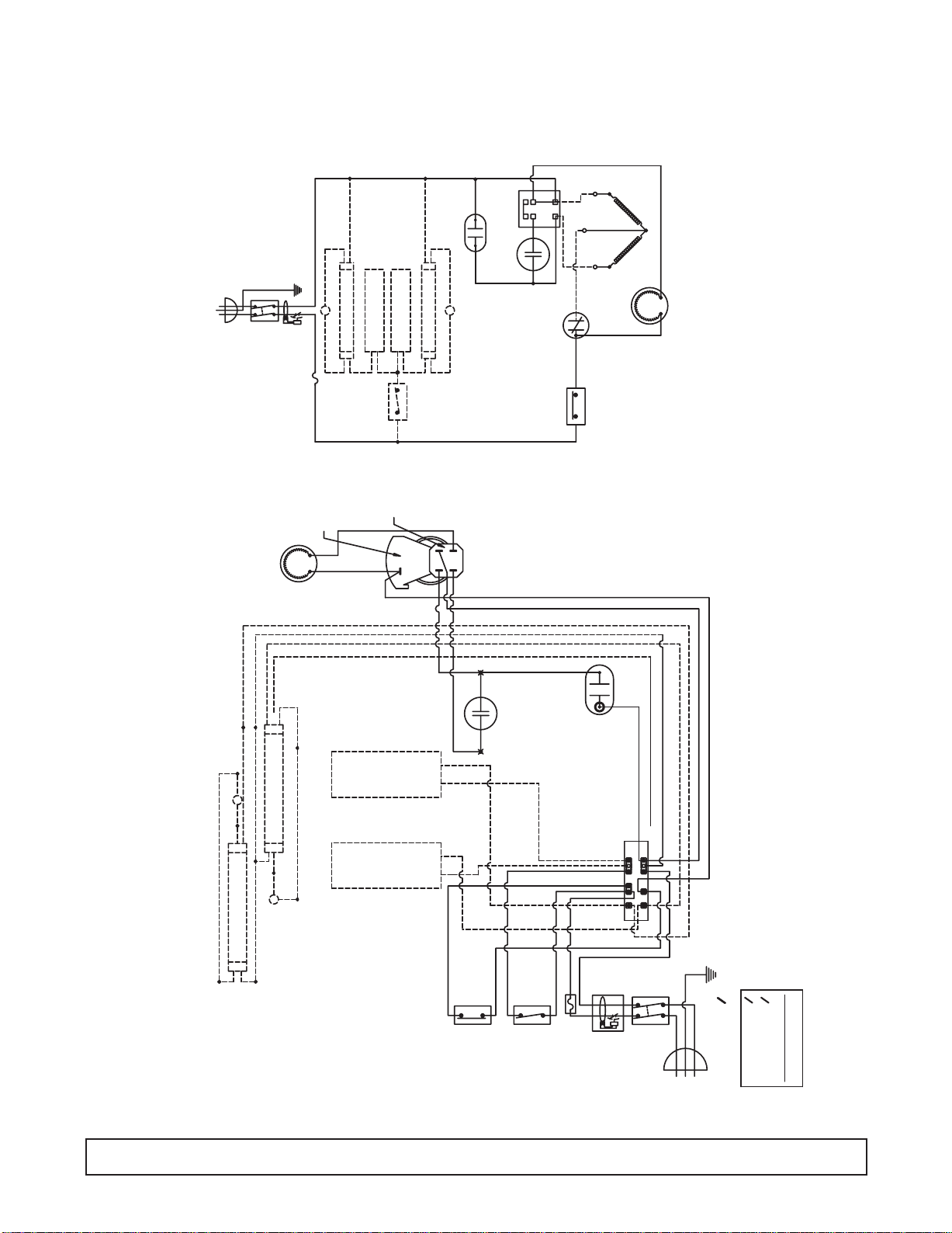
WIRING DIAGRAM - 4HR, 4HC / 8HR, 8HC
E4HR, E4HC / E8HR, E8HC
E4HR2, E4HC2 / E8HR2, E8HC2
SWITCH
SUPPLY
FAN MOTOR
S
GFCI
FUSE
BLACK WHITE
MOTOR PROTECTOR
LAMP
BALLAST
SWITCH
LIGHT
(PTCR)
BALLAST
LAMP
R
C
S
COMPRESSOR
RUN CAP.
(PTCR)
START CAP.
1
2
3
4
S
PROTECTOR
MOTOR
CONTROL
TEMP.
1
2
4
3
TERMINAL BOX
COMPRESSOR
FAN MOTOR
-THE 8HF/4HJ/8HJ HAVE NO LIGHTS.
WIRE DIAGRAM
00-C-2030-00 F
NOTES: -RED WIRE IS AN EXTRA WIRE.
-THE 4HR AND 4HC HAS ONLY ONE LIGHT.
BLUE
S
LAMP
WHITE
BLUE
LAMP
S
BALLAST
BALLAST
BLUE
BLACK
YELLOW
BLACK
BLACK
TEMP.
BLK.BLK.
BLACK
CONTROL
BLACK
BLACK
START CAP.
BLACK
BLACK
LIGHT
SWITCH
( SEE NOTES)
BLACK
BLACK
FUSE
RUN CAP.
WHITE
(SOME MODELS)
TERMINAL
ELB
(SOME MODELS)
BOARD
1
3
5
BLACK
RED (EXTRA)
2
4
6
SWITCH
SUPPLY
WHITE
BLUE
BLACK
L1
(BROWN)
BLUE
WHITE
WHITE
(L2) N
BLACK
(BLUE)
OR
220 VAC. 60 Hz.-10
POWER SUPPLY
115 VAC. 60 Hz.-10
115 VAC. 60 Hz.-10
POWER SUPPLY
220 VAC. 50 Hz.-10
POWER SUPPLY FOR
EXPORT MODELS ONLY
ELECTRICAL INFORMATION.
SEE SERIAL PLATE FOR
22 PRINCIPLES OF OPERATION
 Loading...