


CARRIER COMMERCIAL REFRIGERATION, INC.
Providing BEVERAGE-AIR • FRIGIDAIRE • KELVINATOR • UNIVERSAL NOLIN Products/Services
SERVICE &
INSTALLATION
MANUAL
ICE CREAM
DIPPING
CABINETS
R-404A Refrigerant
1/2003 |
51-1468-01 |
|
|

If additional information is necessary, call the factory.
Our toll free number is 1-800-684-1199. Technical assistance engineers are willing to assist you in any way possible. Office hours are from 8:00a.m. to 5:30 p.m., Eastern Standard Time.
Important information is contained in this manual which should be retained in a convenient location for future reference.
MODEL DESIGNATION INFORMATION
115V, 60HZ
PART # |
MODEL # |
DATA PLATE |
52-1961-35 |
BRT-68 |
BRT68 |
52-2077-02 |
BRT68P |
BRT68 |
52-2077-04 |
BRT68W |
BRT68 |
52-1961-36 |
BRT90 |
BRT90 |
52-2077-03 |
BRT90P |
BRT90 |
52-2077-05 |
BRT90W |
BRT90 |
|
EXPORT 220V, 50HZ |
|
PART # |
MODEL # |
DATA PLATE |
52-1961-31 |
EBRT-68 |
EBRT68 |
52-1961-41 |
EBRT68P |
EBRT68 |
52-1961-32 |
EBRT90 |
EBRT90 |
52-1961-42 |
EBRT90P |
EBRT90 |
|
EXPORT 220V, 60HZ |
|
PART # |
MODEL # |
DATA PLATE |
52-1961-33 |
KBRT-68 |
KBRT68 |
52-1961-34 |
KBRT90 |
KBRT90 |
|
|
|
Manual effective for models produced January, 2003. Starting serial number 6527372.
SECTION I
Introduction
blank
Dipping Cabinets - Introduction
These Dipping Cabinets are designed to merchandise ice cream or yogurt-type products. Dipping cabinets are produced in three sizes: 8, 12, and 16 facings of ice cream containers. The cabinet systems contain CFC free refrigerant, metered into the system by a capillary tube. The evaporator is a cold wall which has the refrigerant lines strapped to the inner liner of the cabinet. The condenser is a bare tube mounted on a pullout machinery compartment tray for ease of servicing. All electrical controls are easily accessible for repair. The temperature within the cabinet is controlled thermostatically, allowing for maintenance of correct dipping temperatures.
Mechanical equipment may require repair at times. This manual presents information that is helpful in maintaining, diagnosing, and repairing these cabinets.
The high level of quality built into these units will allow for many years of trouble-free operation.
INTRODUCTION |
3 |
|
|
TABLE OF CONTENTS |
|
INTRODUCTION |
|
Introduction ........................................................................ |
3 |
Table of Contents ................................................................ |
4 |
Cabinet Specifications / Dimensional Data: BRT-68 ............ |
5 |
Cabinet Specifications / Dimensional Data: BRT-90 ............ |
6 |
Handling & Installation ...................................................... |
7 |
PRINCIPLES OF OPERATION |
|
General Information - Refrigeration Systems .................... |
11 |
BRT-68 Electrical & Refrigeration Information .................. |
13 |
BRT-90 Electrical & Refrigeration Information .................. |
14 |
EBRT-68 & KBRT-68 Electrical & Refrigeration Info ........ |
15 |
EBRT-90 & KBRT-90 Electrical & Refrigeration Info ........ |
16 |
BRT-68 & BRT-90 Wiring Diagram .................................. |
17 |
EBRT/KBRT-68 & 90 Wiring Diagram .............................. |
18 |
MAINTENANCE & REPAIR |
|
Pre-Service Check List ...................................................... |
21 |
General Maintenance Information .................................... |
22 |
Compressor Installation / Diagnostics .............................. |
24 |
Cleaning & Maintenance .................................................. |
26 |
Cleaning the Lid ................................................................ |
27 |
Lid Seal Replacement ...................................................... |
28 |
Lid Gasket Replacement .................................................. |
29 |
Lid Pivot Bushing Assembly Replacement ...................... |
30 |
Center & End Pivot Rod Replacement .............................. |
31 |
Fluorescent Lamp Holder/Light Starter Socket Replac. .... |
32 |
Fluorescent Bulb & Starter Replacement .......................... |
33 |
Thermostat Replacement .................................................. |
34 |
Master Power Supply Switch / Light Switch Removal ...... |
35 |
Condenser Fan Motor Replacement .................................. |
36 |
Ballast Replacement ........................................................ |
37 |
Metering Device / Heat Exchanger Replacement .............. |
38 |
Cabinet Troubleshooting Guide ........................................ |
39 |
Compressor Troubleshooting Guide ................................ |
42 |
Fluorescent Lamp Troubleshooting Guide ........................ |
45 |
PARTS LISTS |
|
Cabinet Parts .................................................................. |
48 |
Lamp Assembly Parts ...................................................... |
50 |
Condensing Unit Parts ...................................................... |
52 |
Electrical Parts .................................................................. |
54 |
Lid Parts .......................................................................... |
56 |
Due to Frigidaire’s policy of continuous quality improvement, specifications are subject to change without notice.
4 |
TABLE OF CONTENTS |
|
|
CABINET SPECIFICATIONS
|
BRT68 |
EBRT68 |
KBRT68 |
|
|
|
|
Temp. Range |
+10°F to -8°F |
|
|
|
|
|
|
Capacity |
19.1 Cu. Ft. |
|
|
|
|
|
|
Capacity (3 Gal. Tubs) |
20 |
|
|
|
|
|
|
Facings (3 Gal. Tubs) |
12 |
|
|
|
|
|
|
Storage (3 Gal. Tubs) |
8 |
|
|
|
|
|
|
Compressor Size |
1/3 Hp. |
3/4 Hp. |
3/4 Hp. |
|
|
|
|
Shipping Weight (App.) |
644 lbs. |
|
|
|
|
|
|
Condenser Type |
Bare Tube |
|
|
|
|
|
|
Evaporator Type |
Cold Wall - Refrigerated Cross Bars |
|
|
|
|
|
|
Refrigerant |
R-404A |
|
|
|
|
|
|
Refrigerant Control |
Capillary Tube |
|
|
|
|
|
|
Defrost System |
Manual |
|
|
|
|
|
|
Rated Amps |
8.0 |
4.1 |
4.1 |
|
|
|
|
Electrical Specs. |
115V, 60 Hz., 1 Ph. |
220V, 50 Hz., 1Ph |
220V, 60 Hz., 1 Ph. |
|
|
|
|
Power Cord |
No. 16AWG |
|
|
|
|
|
|
NSF Listing |
NSF1 |
|
|
|
|
|
|
Canopy Construction |
S.S. Top with Glass Ends Straight or Curved Front Glass |
|
|
|
|
|
|
Lids (Plexiglass) |
2 Lids |
|
|
|
|
|
|
Interior Finish |
White Baked Enamel on Galvanized Steel |
|
|
|
|
|
|
Exterior Finish |
White Baked Enamel |
|
|
|
|
|
|
Lighting |
Two 40 Watt Bulbs |
|
|
|
|
|
|
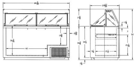
DIMENSIONAL DATA
REAR VIEW |
END VIEW |
INTRODUCTION |
5 |
|
|

CABINET SPECIFICATIONS
|
BRT90 |
EBRT90 |
KBRT90 |
|
|
|
|
Temp. Range |
+10°F to -8°F |
|
|
|
|
|
|
Capacity |
24.4 Cu. Ft. |
|
|
|
|
|
|
Capacity (3 Gal. Tubs) |
28 |
|
|
|
|
|
|
Facings (3 Gal. Tubs) |
16 |
|
|
|
|
|
|
Storage (3 Gal. Tubs) |
12 |
|
|
|
|
|
|
Compressor Size |
1/3 Hp. |
3/4 Hp. |
3/4 Hp. |
|
|
|
|
Shipping Weight (App.) |
754 lbs. |
|
|
|
|
|
|
Condenser Type |
Bare Tube |
|
|
|
|
|
|
Evaporator Type |
Cold Wall - Refrigerated Cross Bars |
|
|
|
|
|
|
Refrigerant |
R-404A |
|
|
|
|
|
|
Refrigerant Control |
Capillary Tube |
|
|
|
|
|
|
Defrost System |
Manual |
|
|
|
|
|
|
Rated Amps |
8.0 |
4.1 |
4.1 |
|
|
|
|
Electrical Specs. |
115V, 60 Hz., 1 Ph. |
220V, 50 Hz., 1Ph |
220V, 60 Hz., 1 Ph. |
|
|
|
|
Power Cord |
No. 16AWG |
|
|
|
|
|
|
NSF Listing |
NSF1 |
|
|
|
|
|
|
Canopy Construction |
S.S. Top with Glass Ends Straight or Curved Front Glass |
|
|
|
|
|
|
Lids (Plexiglass) |
2 Lids |
|
|
|
|
|
|
Interior Finish |
White Baked Enamel on Galvanized Steel |
|
|
|
|
|
|
Exterior Finish |
White Baked Enamel |
|
|
|
|
|
|
Lighting |
Two 40 Watt Bulbs |
|
|
|
|
|
|
DIMENSIONAL DATA
REAR VIEW |
END VIEW |
6 |
INTRODUCTION |
|
|
HANDLING & INSTALLATION-Illuminated Dipping Cabinets
FREIGHT DAMAGES AND SHORTAGES
IMPORTANT
The cabinet was inspected and packaged at the factory, and should have arrived in excellent condition. The transportation company or other parties involved in the shipment are responsible for loss and/or “damage.” Always make an inspection before and after uncrating, preferably at the point of unloading by the transportation company.
INSPECTING FOR DAMAGES
Note:
Always use care when removing shipping tape, blocks, pads, hardware or other material. Contact your dealer or distributor if technical assistance is required.
Check the cartons or containers. If these are damaged in any way, open them and inspect the contents in the driver’s presence. If damage is detected, do the following:
1.Have the driver note the nature and extent of the damage on the freight bill.
2.Notify the transportation company’s office to request an inspection. Carrier claim policies usually require inspections to be made within 15 days of delivery.
3.If damage is noticed, file a claim with the transportation company.
FILING A CLAIM
File a claim for loss at once with the transportation company for:
A. A cash adjustment B. Repairs C. Replacement
When filing your claim, retain all packaging materials and receipts.
HANDLING THE CABINET
Note:
The refrigeration system of the cabinet is designed to operate with the cabinet located on a flat surface. Do not tilt the cabinet more than 30° to any side. If the cabinet must be tilted on an angle for handling or moving purposes, allow it to sit in an upright position 20 to 30 minutes prior to operating.
CHOOSE A LOCATION
This model cabinet should be situated to allow proper air circulation. The cabinet must be installed on sturdy, level floor and positioned so that it can be plugged into a properly grounded three-prong electrical wall outlet. The electrical outlet should not be controlled by a wall switch which might be turned off accidentally.
UNCRATING THE CABINET
The cabinet should be moved as close as possible to the operating location before removing the skid. Be sure to follow the steps in the “INSPECTING FOR DAMAGES” instructions.
INSTALLING THE CABINET
Whenever possible leave the crate skid on the cabinet until it is moved close to the final position. When it is necessary to move the cabinet through a doorway, it may be necessary to remove the crate skid.
Run the cabinet down to storage temperature before adding product.
CAUTION
A.Do not locate cabinet where sunlight or drafts from fans, air conditioners or open doors can affect product temperature.
B.Run cabinet before building in or attaching panels or accessories.
C.Employee side access panel must be kept clear for adjustments and service.
D.Cabinet must be installed on the finished floor to assure rear raceway cover and condensing unit (employee side) can be pulled or removed for service.
DO NOT seal in with cover molding or caulking in the area where condensing unit pulls out.
E.Do not use extension cords to power this equipment.
Run any necessary electrical, water supply and drain lines before setting the cabinet in position. Shim under the cabinet as necessary to level it. N.S.F. approval requires sealing the cabinet to the floor. This can be done by applying a bead of mastic sealer between the cabinet bottom flange and the floor.
Should several cabinets be set up in a row, space is provided in the rear toe space for routing electrical and plumbing lines. Access to this space requires removing screws and the metal cover which runs the length of the cabinet.
Rivnuts are provided on the operator's side for mounting dipperwell and other accessories.
CABINET START-UP
Once the cabinet has been located in its permanent location and the proper power and grounding have been provided, the following items must be checked or completed:
A.Cut and remove the compressor hold-down band (if applicable) so the compressor “floats” freely.
INTRODUCTION |
7 |
|
|
B.Check for traces of oil on the compressor pan which could mean a broken or leaking refrigeration line.
UNDER NO CIRCUMSTANCE SHOULD THE COMPRESSOR BE STARTED WHEN OIL IS PRESENT UNTIL INSPECTED BY A SERVICE TECHNICIAN.
C.INSPECT THE FACTORY WIRING FOR TERMINALS THAT MIGHT HAVE VIBRATED LOOSE IN SHIPPING. TIGHTEN ALL SCREW TYPE TERMINALS.
D.Check the refrigeration lines to see that they are “free” and no damage was done during shipping.
E.Check fan blade for free operation.
F.Turn on the main power switch. Once the compressor starts, the voltage should be checked at the compressor terminals to determine if there is proper voltage to the compressor. The voltage should not exceed the 10% above or below the rated compressor voltage.
EXAMPLE: If the voltage reads 115 volts with no load and it drops below 103 volts when the compressor starts, it may indicate that the supply wiring is too small or that the wire run is too long.
G.Listen for any unusual noise such as lines vibrating, etc. Correct the problem by tightening screws, slightly bending tubing, etc.
H.The temperature control thermostat which is located in the rear post is factory set for average conditions. A customer adjustment requires a coin or screwdriver to turn the slotted shaft. A numbered dial makes it easy to keep track of adjustments. #1 is warmest setting and #7 is coldest setting. An “OFF” position is provided for your convenience in defrosting the cabinet.
I.Allow the cabinet to pull down and cycle prior to loading with product (Approx. 24 hours).
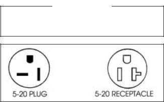
GROUNDING INSTRUCTIONS
This appliance is equipped with a three-prong (grounding) plug for your protection against shock hazards. The appliance should be plugged directly into a properly grounded three-prong receptacle.
Where a two-prong wall receptacle is encountered, it must be replaced with a properly grounded three-prong receptacle in accordance with the National Electrical Code and local codes and ordinances. The work must be done by a licensed electrician.
IMPORTANT
Do not, under any circumstance, cut or remove the round grounding plug from the appliance plug.
WARNING
Consult a licensed electrician if you have any doubt about the grounding of your wall receptacle. Only a licensed electrician can determine the polarization of your wall receptacle. Only a properly installed threepronged wall receptacle assures the proper polarization with the appliance plug.
IMPORTANT USAGE INSTRUCTIONS
Dipping Cabinet
The cabinet must be located in an area free from air drafts created by open doors, air conditioning ducts, and fans. The cabinet should not be located in the direct sunlight.
The rear grill must be clear of any obstructions so the intake and exhausting of air for the condensing unit can move freely.
Dipping cabinets are designed for use in an air conditioned store. This cabinet is designed for merchandising, not hardening of the product.
High humidity can cause fogging of the lid and front glass.
High temperatures, installation of warm product and heavy usage can cause the product to soften. This condition will be more noticeable at the top of the cans.
The corners of the cabinets are the coldest areas. These areas should be used for product that is more difficult to keep firm.
Frost and ice act as insulators. The need for defrosting will depend on usage and product firmness.
If the frost is scraped daily with a plastic scraper, intervals between complete defrosting may be extended.
Thermostat adjustments should be made one increment warmer or colder allowing 24 hours between adjustments to allow the product to stabilize.
8 |
INTRODUCTION |
|
|
SECTION II
Principles of
Operation
blank
GENERAL INFORMATION - REFRIGERATION SYSTEMS
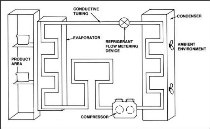
FIGURE 1
Basic refrigeration is based upon the Second Law of Thermodynamics … “Heat will always flow from a warm object to and be absorbed by an object of substance of colder temperature.”
The purpose of a mechanical refrigeration system is to provide for efficient and continuous cooling.
In order for this to take place, the system must provide a means to transfer heat from the products being refrigerated to an area that will not affect the product (See Figure 1).
This is accomplished through the circulation of refrigerant contained in conductive tubing, past the area where the products are stored.
The refrigerant absorbs the heat from the product area and transports it to where the heat can be dissipated into the air outside the cabinet. Four essential components are needed in a simple refrigeration system:
An Evaporator
A Compressor
A Condenser
and a Refrigerant Flow Metering Device
The purpose of the evaporator is to draw the heat from the product or storage area. As low temperature, low pressure liquid refrigerant enters the evaporator, it begins to boil or vaporize as it absorbs the heat of the product and cabinet interior.
The vaporized refrigerant is drawn through the evaporator by the compressor, in addition to causing the necessary flow of refrigerant within the circuit.
The compressor also increases the pressure of the vaporized refrigerant flowing from the compressor to the condenser.
The increased pressure causes the temperature of the refrigerant to rise above the ambient temperature of the room.
This condition allows the heat in this vaporized high pressure refrigerant to be released into the room’s ambient environment.
As heat is released, the vaporized refrigerant returns to a liquid state.
If there is a large amount of heat to be released, this heat transfer is increased by using a fan to ensure a constant flow of cooler ambient air through the condenser coil.
PRINCIPLES OF OPERATION |
11 |
|
|
The cooled liquid refrigerant leaves the condenser under high pressure and travels to the refrigerant flow metering device.
This device regulates the flow of refrigerant into the evaporator.
By restricting this flow, the liquid refrigerant moves to the evaporator under low pressure. (See FIGURE 1)
This lower pressure is necessary for the refrigerant to have the capability to vaporize and absorb heat.
The cycle will continue until the desired temperature within the product area is reached.
At this point, the compressor shuts off and the refrigerant cycle is interrupted until further cooling is required.
This simple refrigeration system is known as a single stage system. It is the most common refrigeration system and is used for applications where the product area temperatures do not exceed -20° Fahrenheit.
The single stage system is used on product dipping cabinets.
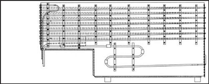
Product dipping cabinets utilize a cold wall evaporator. (See FIGURE 2).
Here the refrigerant lines actually contact the product area’s inner wall. Heat is transferred through the wall and into the refrigerant.
To understand how the refrigerant system creates cold temperatures, it is important to understand how the temperatures of the area into which the heat will be dissipated affect the system’s performance.
Simply stated, a refrigerant system’s ability to cool a product area is dependent upon the unit’s ambient environment.
For example, a single stage system dissipating heat throught its condenser into a 60°F ambient environment is capable of cooling a cabinet’s interior to a lower temperatue than an identical system operaing in an 80°F ambient environment.
To understand the complete heat transfer and extraction process in systems, let’s discuss the function of the major system components.
There are three components in each system used for transferring heat. They are the Evaporator, the Compressor, and the Condenser.
Heat is transferred through the refrigerant lines by the compressor. This heated refrigerant arrives at the condenser for dissipation.
The heat transfers to the evaporator because it is colder.
The heat then moves through the compressor and leaves the cabinet at the condenser, where it transfers or dissipates into the cooler room air.
This heat transfer continues until the system has absorbed all the heat it is capable of removing, and has pulled down to the coldest temperature possible, or it has reached its thermostatic set point and shuts off.
On product dipping cabinets, the copper evaporator lines are strapped to the inner tank walls to form a cold wall evaporator.
This is foamed into place with two inches of urethane instulation to form a rigid bond between the outer shell and inner liner, which is another metal barrier used for strength and insulation separation.
The direction of the refrigerant flow is from the top to the bottom.
The cold wall evaporator is not serviceable within the walls of the cabinet because of the foam construction.
FIGURE 2
12 |
PRINCIPLES OF OPERATION |
|
|
SYSTEM INFORMATION - BRT-68 ELECTRICAL
Compressor |
Manufacturer: Americold |
||
|
Model: HP-127-1 |
||
|
Ph.: 1 |
Hz.: 60 |
|
|
Volts: 115 |
Amps: 4.2 |
|
|
|
||
Overload Protector |
Manufacturer: Americold |
||
|
|
||
Start Relay |
Manufacturer: Americold |
||
|
|
|
|
Start Capacitor |
V.: 125 |
M.F.: 189-227 |
|
|
|
|
|
Run Capacitor |
VAC: 370 |
M.F.: 20 |
|
|
|
||
|
|
||
Condenser |
Manufacturer: Heatcraft |
||
|
|
||
Condenser |
Manufacturer: G.E. |
||
Fan Motor |
Model: 5KSM51GG3784 |
||
|
|
||
Condenser |
Diameter: 9.5" # Blades: 3 |
||
Fan Blade |
Width of Blades: 1 29/32" |
||
|
|
|
|
Evaporator |
|
|
Cold Wall |
|
|
|
|
|
|
|
|
Capillary Tube |
|
|
7' of .042 |
|
|
|
|
|
|
|
|
|
|
|
|
|
|
Thermostat |
|
Manufacturer: Ranco |
|
||
|
|
F.L.A.: 25 |
|
||
|
|
V.: 120/250 L.R.A.: 100 |
|||
|
|
|
|
|
|
Warm Cut-in |
11° |
Warm Cut-out |
— |
||
|
|
|
|
|
|
Mid Cut-in |
-12° |
Mid Cut-out |
-24° |
||
|
|
|
|
||
Cold Cut-in |
— |
Cold Cut-out -34° |
|||
|
|
|
|
|
|
|
|
|
|
|
|
Power Cord |
|
A.W.G.: 16 |
|
||
|
|
|
A.: 15 V.: 125 |
|
|
|
|
|
|
|
|
Light Ballast |
|
Manufacturer: G.E. |
|||
|
|
|
Model: 89G457 |
|
|
|
|
|
|
|
|
Fluorescent |
|
Manufacturer: G.E. |
|||
Lamp |
|
F40T12CW |
|
||
|
|
|
|
|
|
REFRIGERATION - Refrig. Charge: R-404A / 25 oz. / 708.75 grams / No. 4 Stat Position
AMBIENT TEMPERATURE |
70°F / 21.1°C |
80°F / 27°C |
90°F / 32.5°C |
|||
Suction Pressure - C.O. PSIG/Kpa |
9 |
/ 62 |
10 |
/ 69 |
11 |
/ 76 |
|
|
|
|
|
|
|
Discharge Pressure - C.O. PSIG/Kpa |
198 |
/ 1365 |
230 |
/ 1586 |
268 |
/ 1848 |
|
|
|
|
|||
Compressor Amps |
4.2 |
4.2 |
4.3 |
|||
|
|
|
|
|||
Total Cabinet Amps |
6.1 |
6.1 |
6.2 |
|||
|
|
|
|
|||
Cavity Temperature |
0°F / -17°C |
1°F / -17°C |
2°F / -16°C |
|||
|
|
|
|
|
|
|
PRINCIPLES OF OPERATION |
13 |
|
|
SYSTEM INFORMATION - BRT-90 ELECTRICAL
Compressor |
Manufacturer: Americold |
|
|
Model: HP-127-1 |
|
|
Volts: 115 Amps: 4.2 |
|
|
L.R.A.: — Ph.: 1 Hz.: 60 |
|
|
|
|
Overload Protector |
Americold #1456-3321 |
|
|
|
|
Start Relay |
Americold #1456-3374 |
|
|
|
|
Start Capacitor |
V.: 125 |
M.F.: 189-227 |
|
|
|
Run Capacitor |
V: 370 |
M.F.: 20 |
|
|
|
|
|
|
Condenser |
Manufacturer: Heatcraft |
|
|
|
|
Condenser |
Manufacturer: G.E. |
|
Fan Motor |
Model: 5KSM51GG3784 |
|
|
|
|
Condenser |
Diameter: 9.5" # Blades: 3 |
|
Fan Blade |
Width of Blades: 1 29/32" |
|
|
|
|
Evaporator |
|
|
Cold Wall |
|
|
|
|
|
|
|
|
Capillary Tube |
|
|
7' of .042 |
|
|
|
|
|
|
|
|
|
|
|
|
|
|
Thermostat |
|
Manufacturer: Ranco |
|
||
|
|
F.L.A.: 25 |
|
||
|
|
V.: 120/240 L.R.A.: 100 |
|||
|
|
|
|
|
|
Warm Cut-in |
11° |
Warm Cut-out |
— |
||
|
|
|
|
|
|
Mid Cut-in |
-12° |
Mid Cut-out |
-24° |
||
|
|
|
|
||
Cold Cut-in |
— |
Cold Cut-out -34° |
|||
|
|
|
|
|
|
|
|
|
|
|
|
Power Cord |
|
A.W.G.: 16 |
|
||
|
|
|
A.: 15 V.: 125 |
|
|
|
|
|
|
|
|
Light Ballast |
|
Manufacturer: G.E. |
|||
|
|
|
Model: 8G3706 |
|
|
|
|
|
|
|
|
Fluorescent |
|
Manufacturer: G.E. |
|||
Lamp |
|
F40T12CW |
|
||
|
|
|
|
|
|
REFRIGERATION - Refrig. Charge: R-404A / 27 oz. / 765.45 grams / No. 4 Stat Position
AMBIENT TEMPERATURE |
70°F / 21.1°C |
80°F / 27°C |
90°F / 32.5°C |
|||
CONTROL SETTINGS |
#4 C.S. |
#4 C.S. |
#4 C.S. |
|||
Suction Pressure - C.O. PSIG/Kpa |
9 |
/ 62 |
10 |
/ 69 |
12 |
/ 82 |
|
|
|
|
|
|
|
Discharge Pressure - C.O. PSIG/Kpa |
207 |
/ 1427 |
234 |
/ 1613 |
262 |
/ 1806 |
|
|
|
|
|||
Compressor Amps |
3.8 |
3.8 |
3.9 |
|||
|
|
|
|
|||
Total Cabinet Amps |
6.3 |
6.3 |
6.3 |
|||
|
|
|
|
|||
Cavity Temperature |
-0.5°F / -18°C |
-0.3°F / -17.9°C |
-1.2°F / -18.4°C |
|||
|
|
|
|
|
|
|
14 |
PRINCIPLES OF OPERATION |
|
|
SYSTEM INFORMATION - EBRT-68 (220V / 50 Hz) ELECTRICAL KBRT-68 (220V / 60 Hz)
Compressor |
|
Mfg: Copeland (3/4 HP) |
|
|
Model: KAMB-007E-CAV |
|
|
Phase: 1 Hz.:50 |
|
|
|
Overload Protector |
|
Model No.: 071-0092-29 |
|
|
|
Start Relay |
|
G.E. 3ARR3CT3E5 |
|
|
Pick up: 340-360 |
|
|
Drop out: 45-115 |
|
|
Model No.: 040-0001-03 |
|
|
|
Start Capacitor |
|
V: 220 |
|
|
M.F.: 145-174 |
|
|
|
|
|
|
Condenser |
Manufacturer: Heatcraft |
|
|
|
|
Condenser |
Manufacturer: G.E. |
|
Fan Motor |
Model: KSM51GG3705 |
|
|
|
|
Condenser |
Diameter: 91⁄2" # Blades: 3 |
|
Fan Blade |
Width of Blades: 129⁄32" |
|
|
|
|
High Pressure |
Ranco |
|
Switch |
Preset 400 PSIG Diff 100 PSIG |
|
|
|
|
Evaporator |
|
Cold Wall |
|
|
|
|
|
|
|
Capillary Tube |
|
9' of .042 |
|
|
|
|
|
|
|
|
|
|
|
|
Thermostat |
|
Manufacturer: Ranco |
|
|
|
|
F.L.A.: 25 |
|
|
|
|
V.: 125/250 L.R.A.: 100 |
||
|
|
|
|
|
Warm Cut-in |
11° |
Warm Cut-out |
— |
|
|
|
|
|
|
Mid Cut-in |
-12° |
Mid Cut-out |
-24° |
|
|
|
|
|
|
Cold Cut-in |
— |
Cold Cut-out -34° |
||
|
|
|
|
|
|
|
|
|
|
Power Cord |
A.W.G.: 16 |
|
||
|
|
Amp: 15 |
|
|
|
|
|
|
|
Light Ballast |
Mfg: Vossloh Schwabe |
|||
|
|
Model: L36.291 (50 Hz) |
||
|
|
Robertson: 1-4026 (60 Hz) |
||
|
|
|
|
|
Fluorescent |
Manufacturer: G.E. |
|
||
Lamp |
F40T12CW |
|
||
|
|
|
|
|
|
|
|
|
|
REFRIGERATION - Refrig. Charge: R-404A / 25 oz. / 708.75 grams / No. 4 Stat Position
AMBIENT TEMPERATURE |
70°F / 21.1°C |
80°F / 27°C |
90°F / 32.5°C |
|||
CAVITY TEMPERATURE |
2°F / -17°C |
4°F / -16°C |
6°F / -14°C |
|||
|
|
|
|
|
|
|
Suction Pressure - C.O. PSIG/Kpa |
8 |
/ 55 |
10 |
/ 69 |
12 |
/ 82 |
|
|
|
|
|
|
|
Discharge Pressure - C.O. PSIG/Kpa |
188 |
/ 1296 |
225 |
/ 1551 |
253 |
/ 1744 |
|
|
|
|
|||
Compressor Amps |
7.2 |
7.1 |
7.1 |
|||
|
|
|
|
|||
Total Cabinet Amps |
9.5 |
9.3 |
9.4 |
|||
|
|
|
|
|
|
|
PRINCIPLES OF OPERATION |
15 |
|
|
SYSTEM INFORMATION - EBRT-90 (220V / 50 Hz) ELECTRICAL KBRT-90 (220V / 60 Hz)
Compressor |
|
Mfg: Copeland (3/4 HP) |
|
|
Model: KAMB-007E-CAV |
|
|
Phase: 1 Hz.:50 |
|
|
|
Overload Protector |
|
Copeland |
|
|
Model No.: 071-0092-20 |
|
|
|
Start Relay |
|
G.E. 3ARR3CT3E5 |
|
|
|
Start Capacitor |
|
V: 220 |
|
|
M.F.: 145-174 |
|
|
|
Run Capacitor |
|
V: 370 |
|
|
M.F.: 10 |
|
|
|
|
|
|
Condenser |
Manufacturer: Heatcraft |
|
|
|
|
Condenser |
Manufacturer: G.E. |
|
Fan Motor |
Model: KSM51GG370E |
|
|
115V / 60 Hz. / Ph. 1 |
|
|
|
|
Condenser |
Diameter: 91⁄2" # Blades: 3 |
|
Fan Blade |
Width of Blades: 129⁄32" |
|
|
|
|
High Pressure |
Ranco |
|
Switch |
Preset 400 PSIG Diff 100 PSIG |
|
|
|
|
Evaporator |
|
Cold Wall |
|
|
|
|
|
|
|
Capillary Tube |
|
9' of .049 |
|
|
|
|
|
|
|
|
|
|
|
|
Thermostat |
|
Manufacturer: Ranco |
|
|
|
|
Model No.: 9540N46 |
|
|
|
|
F.L.A.: 25 |
|
|
|
|
V.: 125/250 L.R.A.: 100 |
||
|
|
|
|
|
Warm Cut-in |
11° |
Warm Cut-out |
— |
|
|
|
|
|
|
Mid Cut-in |
-12° |
Mid Cut-out |
-24° |
|
|
|
|
|
|
Cold Cut-in |
— |
Cold Cut-out -34° |
||
|
|
|
|
|
|
|
|
|
|
Power Cord |
A.W.G.: 16 |
|
||
|
|
V.: 220 Amp: 15 |
|
|
|
|
|
|
|
Light Ballast |
Mfg: Vossloh Schwabe |
|||
|
|
Model: L36.291 (50 Hz) |
||
|
|
Robertson: 1-4025 (60 Hz) |
||
|
|
|
|
|
Fluorescent |
Manufacturer: G.E. |
|
||
Lamp |
F40T12CW |
|
||
|
|
|
|
|
|
|
|
|
|
REFRIGERATION - Refrig. Charge: R-404A / 27 oz. / 765.45 grams / No. 4 Stat Position
AMBIENT TEMPERATURE |
70°F / 21.1°C |
80°F / 27°C |
90°F / 32.5°C |
||||
CAVITY TEMPERATURE |
2°F / -17°C |
4°F / -16°C |
7°F / -14°C |
||||
|
|
|
|
|
|
|
|
Suction Pressure - C.O. PSIG/Kpa |
8 |
/ 55 |
10 |
/ 69 |
12 |
/ |
82 |
|
|
|
|
|
|
|
|
Discharge Pressure - C.O. PSIG/Kpa |
228 |
/ 1572 |
257 |
/ 1772 |
284 |
/ |
1958 |
|
|
|
|
|
|
||
Compressor Amps |
7.4 |
7.5 |
|
8 |
|
||
|
|
|
|
|
|||
Total Cabinet Amps |
9.5 |
9.3 |
10 |
|
|||
|
|
|
|
|
|
|
|
16 |
PRINCIPLES OF OPERATION |
|
|
 Loading...