

Libretto di Istruzioni
Bedienungsanleitung
Instructions Manual
Manuel d’Instructions
Gebruiksaanwijzing
Manual de instrucciones
Brugsvejledning
Käyttöohje
Bruksanvisning
Bruksanvisning
Instrukcja Obsługi
KIN52MOD1XC
KIN70MOD1XB
KIN86MOD1XB
IT
DE
EN
FR
NL
ES
DK
FI
NO
SE
PL
INDICE
INFORMAZIONI SULLA SICUREZZA...................................................................................................................................... 4
CARATTERISTICHE.............................................................................................................................................................. 7
INSTALLAZIONE ................................................................................................................................................................... 8
USO...................................................................................................................................................................................... 10
PULIZIA E MANUTENZIONE................................................................................................................................................. 11
IT
INHALTSVERZEICHNIS
SICHERHEITSINFORMATIONEN......................................................................................................................................... 13
CHARAKTERISTIKEN......................................................................................................................................................... 16
MONTAGE ...........................................................................................................................................................................17
BEDIENUNG........................................................................................................................................................................ 19
REINIGUNG UND WARTUNG............................................................................................................................................... 20
INDEX
SAFETY INFORMATION....................................................................................................................................................... 22
CHARACTERISTICS ........................................................................................................................................................... 25
INSTALLATION.................................................................................................................................................................... 26
USE...................................................................................................................................................................................... 28
CARE AND CLEANING......................................................................................................................................................... 29
SOMMAIRE
CONSIGNES DE SÉCURITÉ................................................................................................................................................. 31
CARACTERISTIQUES......................................................................................................................................................... 34
INSTALLATION.................................................................................................................................................................... 35
UTILISATION .......................................................................................................................................................................37
NETTOYAGE ET ENTRETIEN.............................................................................................................................................. 38
INHOUDSOPGAVE
VEILIGHEIDSINFORMATIE................................................................................................................................................... 40
EIGENSCHAPPEN ..............................................................................................................................................................43
INSTALLATIE....................................................................................................................................................................... 44
GEBRUIK .............................................................................................................................................................................46
REINIGING EN ONDERHOUD.............................................................................................................................................. 47
DE
EN
FR
FR
NL
NL
2
ES
2
INDICE
INFORMACIÓN DE SEGURIDAD.......................................................................................................................................... 49
CARACTERÍSTICAS ........................................................................................................................................................... 52
INSTALACIÓN ..................................................................................................................................................................... 53
USO...................................................................................................................................................................................... 55
LIMPIEZA Y MANTENIMIENTO............................................................................................................................................. 56
INDHOLD
OPLYSNINGER OM SIKKERHED......................................................................................................................................... 58
APPARATBESKRIVELSE ................................................................................................................................................... 61
INSTALLATION.................................................................................................................................................................... 62
BRUG................................................................................................................................................................................... 64
RENGØRING OG VEDLIGEHOLDELSE ...............................................................................................................................65
DK
SISÄLTÖ
TURVALLISUUSTIETOJA..................................................................................................................................................... 67
MITAT JA OSAT .................................................................................................................................................................. 70
ASENNUS............................................................................................................................................................................ 71
KÄYTTÖ............................................................................................................................................................................... 73
PUHDISTUS JA HUOLTO..................................................................................................................................................... 74
INNHOLD
SIKKERHETSINFORMASJON.............................................................................................................................................. 76
EGENSKAPER..................................................................................................................................................................... 79
INSTALLASJON................................................................................................................................................................... 80
BRUK ................................................................................................................................................................................... 82
RENGJØRING OG VEDLIKEHOLD....................................................................................................................................... 83
INNEHÅLL
SÄKERHETSINFORMATION................................................................................................................................................ 85
EGENSKAPER..................................................................................................................................................................... 88
INSTALLATION.................................................................................................................................................................... 89
ANVÄNDING........................................................................................................................................................................ 91
NGÖRING OCH UNDERHÅL ................................................................................................................................................ 92
SPIS TREŚCI
INFORMACJE DOTYCZĄCE BEZPIECZEŃSTWA................................................................................................................ 94
WŁAŚCIWOŚCI TECHNICZNE........................................................................................................................................... 97
INSTALACJA........................................................................................................................................................................ 98
UŻYTKOWANIE................................................................................................................................................................. 100
CZYSZCZENIE I KONSERWACJA...................................................................................................................................... 101
FI
NO
SE
PL
3
3

INFORMAZIONI SULLA SICUREZZA
Per la propria sicurezza e per il corretto funzionamento dell’apparecchio, si
prega di leggere attentamente questo manuale prima dell’installazione e
della messa in funzione. Tenere queste istruzioni sempre insieme
all’apparecchio, anche in caso di cessione o trasferimento a terzi. È
importante che gli utilizzatori conoscano tutte le caratteristiche di
funzionamento e sicurezza dell’apparecchio.
Il collegamento dei cavi deve essere effettuato da un tecnico competente.
Il fabbricante non potrà ritenersi responsabile per even
•
un’installazione o utilizzazione impropria.
La distanza minima di sicurezza tra il piano cottura e la cappa as
•
650 mm (alcuni modelli pos
vedere il paragrafo relativo alle dimensioni di lavoro e all’installazione).
•
Se le istruzioni di installazione del piano co
distanza maggiore di quella sopra indicata, è necessario tenerne conto.
Controllare che la tensione di rete corrisponda a quella indicata
•
dati applic
I dispositivi di sezionamento devono essere installati nell’impianto fiss
•
conform
•
Per gli apparecchi di Classe I, controllare che la
domestica dis
•
Collegare la cappa alla canna fumaria con un tubo di diametro minimo
mm. Il percorso dei fumi deve essere il più corto possibile.
Devono essere rispettate tutte le normative riguardant
•
Non collegare la cappa aspirante ai condotti fumari che trasportano fu
•
combustione (per es. di caldaie, cam
ata all’interno della cappa.
ità alle normative sui sistemi di c
ponga di un a
sono essere installati
ttura a gas specificano una
ablaggio.
rete di alimentazione
deguato collegamento a massa.
ini ecc.).
tuali danni risultanti da
pirante è di
a un’altezza inferiore;
sulla targa
i lo scarico dell’aria.
o in
di 120
mi di
IT
4
4
• Se la cappa è utilizzata in combinazione con apparecchi non elettrici (per es.
apparecchi a gas), deve essere garantito un sufficiente grado di aerazione nel
locale per impedire il ritorno di flusso dei gas di scarico. Quando la cappa per
cucina è utilizzata in combinazione con apparecchi non alimentati dalla
corrente elettrica, la pressione negativa nel locale non deve superare 0,04
mbar per evitare che i fumi vengano riaspirati nel locale dalla cappa.
•
L’aria non dev
scarico dei fumi da apparecchi di combustione alimentati a gas o altri
combustibili.
• Il cavo di alimentazione, se danneggiato, deve essere sostituito dal
fabbricante o da un tecnico del servizio assistenza.
•
Collegare la sp
posizione accessibile.
• Relativamente alle misure tecniche e di sicurezza da adottare per lo scarico
dei fumi è importante attenersi scrupolosamente ai regolamenti stabiliti dalle
autorità locali.
e essere evacuata attraverso un condotto utilizzato per lo
ina ad una presa di tipo conforme alle normative vigenti e in
AVVERTENZA: prima di installare la cappa, rimuovere le pellicole di
protezione.
• Usare solo viti e minuteria di tipo idoneo per la cappa.
AVVERTENZA: la mancata installazione delle viti o dei dispositivi di
fissaggio in conformità alle presenti istruzioni può comportare rischi di
scosse elettriche.
• Non osservare direttamente con strumenti ottici (binocolo, lente
d’ingrandimento….).
•
Non cuocere al flambé sotto la cappa: si potrebbe svilu
• Questo apparecchio può essere utilizzato da bambini di età non inferiore a 8
anni e da persone con ridotte capacità psico-fisico-sensoriali o con
esperienza e conoscenze insufficienti, purché attentamente sorvegliati e
istruiti su come utilizzare in modo sicuro l’apparecchio e sui pericoli che ciò
comporta. Assicurarsi che i bambini non giochino con l’apparecchio. Pulizia e
manutenzione da parte dell’utente non devono essere effettuate da bambini,
a meno che non siano sorvegliati.
•
Sorvegliare i bambini, assicurandosi che non giochino con l’apparecchio.
ppare un incendio.
IT
5
5
• L’apparecchio non deve essere utilizzato da persone (bambini compresi) con
ridotte capacit
insufficienti, a meno che non siano attent
à psico-fisico-sensoriali o con esperienz
amente sorvegliate e istruite
a e conoscenze
.
Le parti accessibili possono diventare molto calde durante l’uso degli
apparecchi di cottura.
Pulire e/o sostituire i filtri dopo il periodo di tempo specif
•
incendio). Vedere il paragrafo Manutenz
•
Deve essere presente un’adeguata ventilazione nel loca
è utilizz
ata contemporaneamente ad apparecchi che ut
combustibili (non applicabile ad apparec
nel locale)
.
ione e pulizia.
chi che scaric
icato (pericolo di
le quando la cappa
ilizzano gas o altri
ano unicamente l’aria
• Il
simbolo
può essere s
smaltire deve essere conferito press
sul prodotto o sulla sua confezione indica che il prodotto non
maltito come un normale rifiuto domestico
o un apposito centro di raccolt
. Il prodotto da
a per il
riciclaggio dei componenti elettrici ed elettronici. Assicurandosi che questo
prodotto sia s
conseguenze negativ
altrim
enti derivare dal suo smaltimento inadeguato. Per
maltito correttamente,
e per l’ambiente e
si contribuirà a prevenire potenziali
per la salute che potrebbero
informazioni più
dettagliate sul riciclaggio di questo prodotto, contattare il Comune, il servizio
locale di smaltimento rifiuti oppure il negozio dove è stato acquistato il
prodotto.
IT
6
6

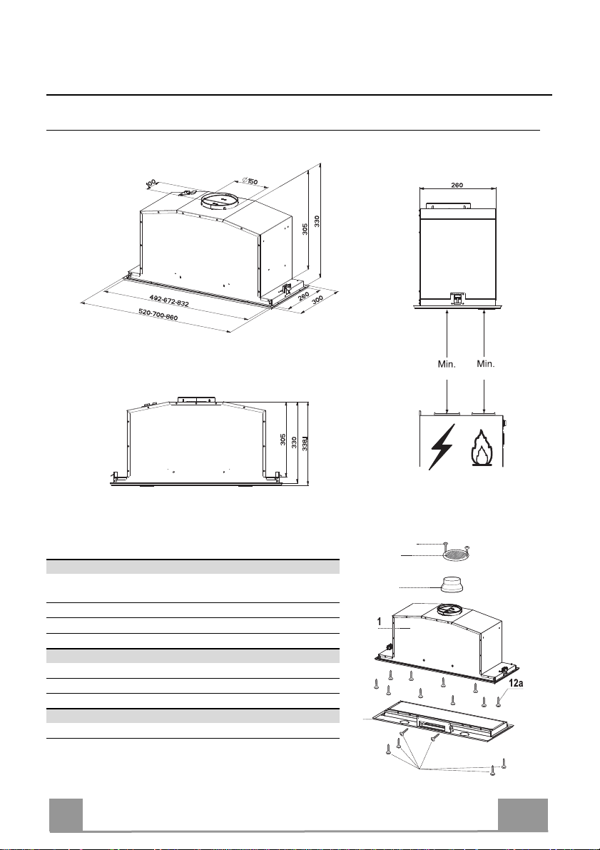
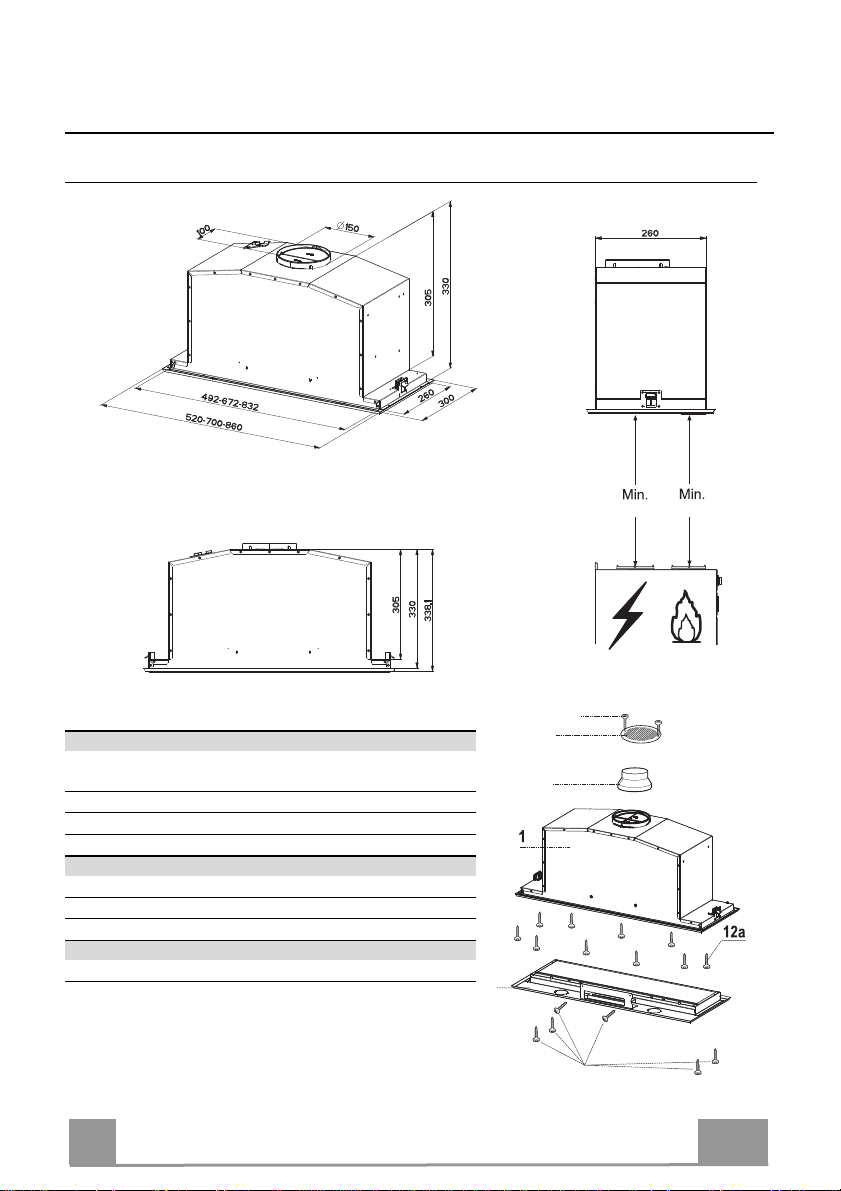
CARATTERISTICHE
Ingombro
530 mm530 mm
Componenti
Rif. Q.tà Componenti di Prodotto
1 1 Corpo Cappa completo di: Comandi, Luce, Filtri, Grup-
po Aspiratore.
2 1 Cornice
8 1 Griglia Direzionata
9 1 Flangia di riduzione ø 150-120 mm
Rif. Q.tà Componenti di Installazione
12a 10 Viti
12e 2 Viti 2,9 x 9,5
12f 6 Viti 2,9 x 6,5
Q.tà Documentazione
1 Libretto Istruzioni
IT
12e
8
9
2
12f
7
7
INSTALLAZIONE
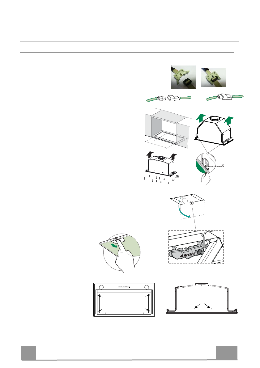
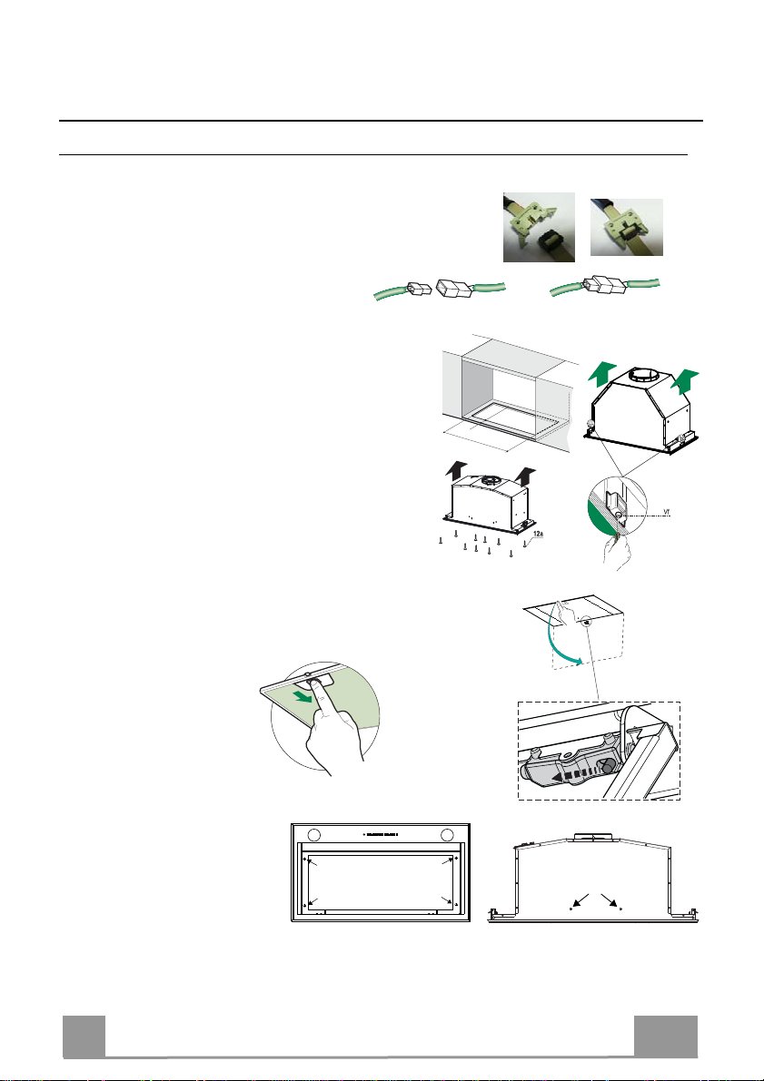
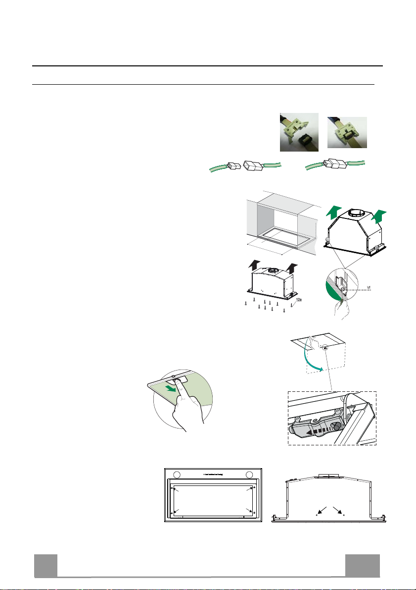
Montaggio Corpo Cappa
PRIMA DI MONTARE LA CAPPA AL PENSILE AGIRE COME SEGUE:
• Scollegare il Cablaggio dei Comandi agendo sui connettori.
• Scollegare il Cablaggio Luci agendo sui connettori.
• La Cappa può essere installata direttamente sul piano
inferiore dei Pensili.
• Praticare un incasso sul piano inferiore del Pensile, come indicato.
• Inserire la Cappa fino ad agganciare i Supporti laterali a
scatto.
• Fissare con 10 Viti 12a in dotazione.
• Bloccare definitivamente serrando le Viti Vf dal sotto
della Cappa.
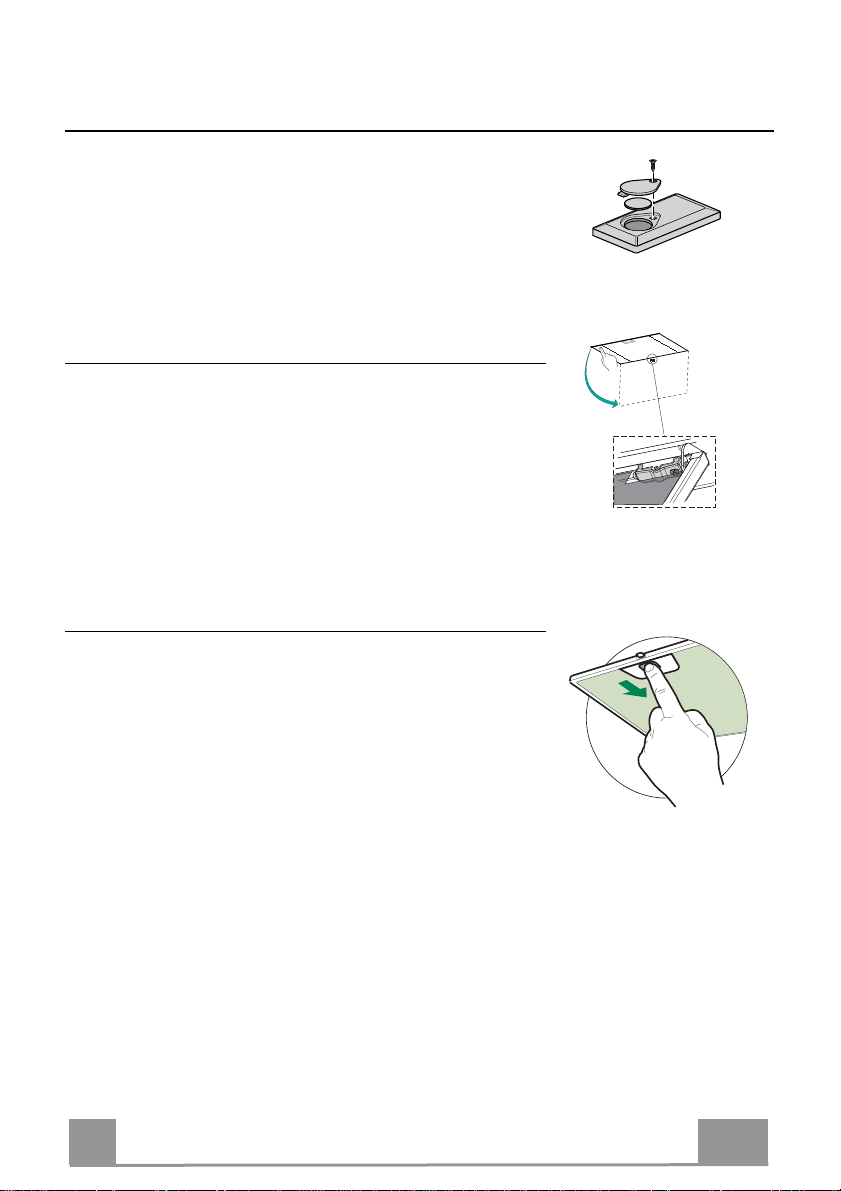
• Aprire il pannello aspirante tirandolo.
• Sganciare il pannello dal corpo cappa facendo scorrere l’apposita
leva del perno di fissaggio.
495 - 675 - 835
260
13
• Togliere i filtri Antigrasso.
• Avvitare la Cornice con le 6
ricollegare il Cablag-
Viti 12f,
gio dei Comandi e Luci, rimontare il filtro Antigrasso e il
Pannello.
IT
8
8
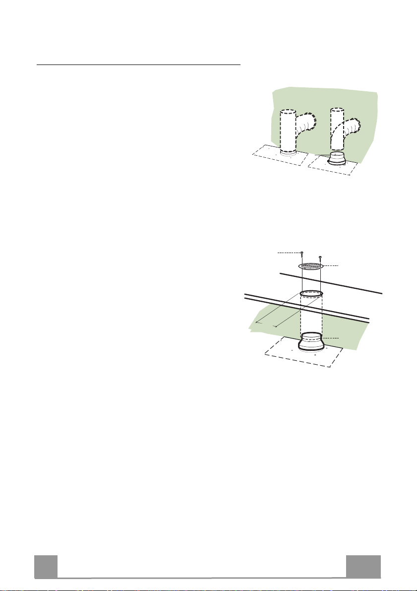
Connessioni
USCITA ARIA VERSIONE ASPIRANTE
Per installazione in Versione Aspirante collegare la
Cappa alla tubazione di uscita per mezzo di un tubo
rigido o flessibile di ø150 o 120 mm, la cui scelta è lasciata all'installatore.
• Per collegamento con tubo ø120 mm, inserire la
Flangia di riduzione 9 sull’Uscita del Corpo Cappa.
• Fissare il tubo con adeguate fascette stringitubo. Il
materiale occorrente non è in dotazione.
• Togliere eventuali Filtri Antiodore al Carbone attivo.
ø 150
ø 120
9
USCITA ARIA VERSIONE FILTRANTE
• Praticare un foro ø 125 mm sull’eventuale Mensola
soprastante la Cappa.
• Inserire la Flangia di riduzione 9 sull’uscita del Corpo Cappa.
• Collegare la Flangia al foro di uscita sulla Mensola
soprastante la Cappa con un tubo rigido o flessibile di
ø120 mm.
• Fissare il tubo con adeguate fascette stringitubo. Il
materiale occorrente non è in dotazione.
• Fissare la Griglia direzionata 8 sull’uscita con 2 Viti
12e (2,9 x 9,5) in dotazione.
• Assicurarsi della presenza dei Filtri antiodore al Carbone attivo.
CONNESSIONE ELETTRICA
• Collegare la Cappa all’Alimentazione di Rete interponendo un Interruttore bipolare con apertura dei contatti di almeno 3 mm.
ø 125
12e
8
9
IT
9
9
USO
S1
L
T1 T2 T3 T4
L
T1 T4
T3S1T2
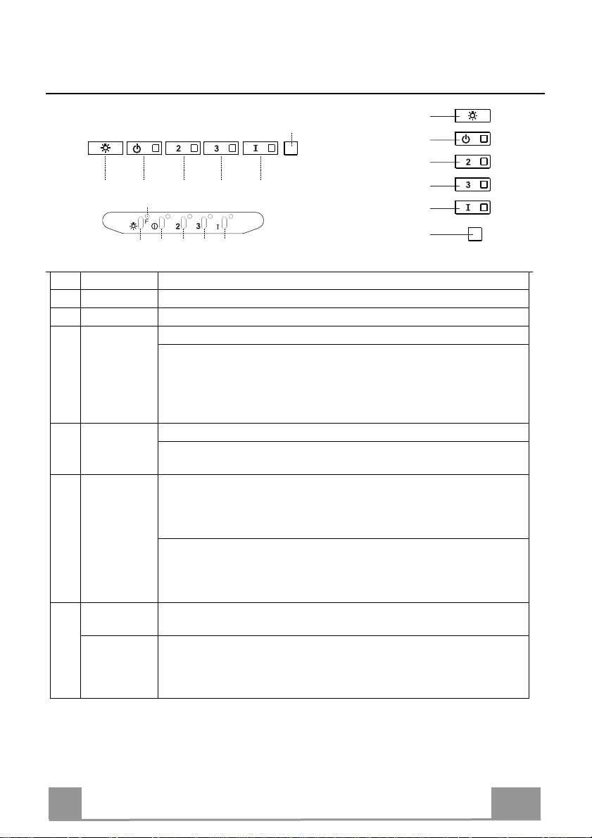
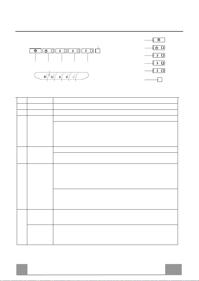
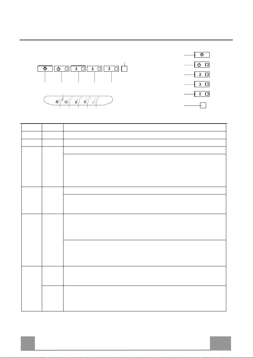
Quadro comandi
Tasto Led Funzione
L
- Accende/Spegne le luci alla massima luminosità..
T1
Fisso Accende/Spegne il motore alla prima velocità.
T2
Fisso
Accende il motore alla seconda velocità.
Tenendo il tasto premuto per circa 5 secondi, quando tutti i carichi sono spenti
(Motore+Luce), si attiva l’allarme dei Filtri al Carbone attivo visualizzando un
doppio lampeggio del relativo Led.
Per disattivarlo, si preme di nuovo il tasto per altri 5 secondi visualizzando un
lampeggio singolo del relativo Led.
T3
Fisso
Accende il motore alla terza velocità.
Tenendo premuto il tasto per circa 3 secondi, quando tutti i carichi sono spenti
(Motore+Luce), si effettua il reset visualizzando il triplo lampeggio del Led S1.
T4
Fisso
Accende il motore alla velocità INTENSIVA.
Questa velocità è temporizzata a 6 minuti. Terminato il tempo, il sistema ritorna
automaticamente alla velocità precedentemente selezionata. Se attivata da motore spento una volta finito il tempo passa alla modalità OFF.
Tenendo premuto per 5 secondi si abilità il telecomando visualizzando un doppio lampeggio del medesimo led.
Tenendo il tasto premuto per 5 secondi si disabilita il telecomando visualizzando il lampeggio del rispettivo led una sola volta.
S1
Fisso Segnala l’allarme saturazione Filtri Antigrasso Metallici e la necessità di lavar-
li. L’allarme entra in funzione dopo 100 ore di lavoro effettivo della Cappa.
Lampeggiante Segnala, quando è attivato, l’allarme saturazione Filtro Antiodore al Carbone
Attivo, che deve essere sostituito; devono anche essere lavati i Filtri Antigrasso
Metallici. L’allarme saturazione Filtro Antiodore al Carbone Attivo entra in
funzione dopo 200 ore di lavoro effettivo della Cappa.
L
T1
T2
T3
T4
S1
IT
10
1
PULIZIA E MANUTENZIONE
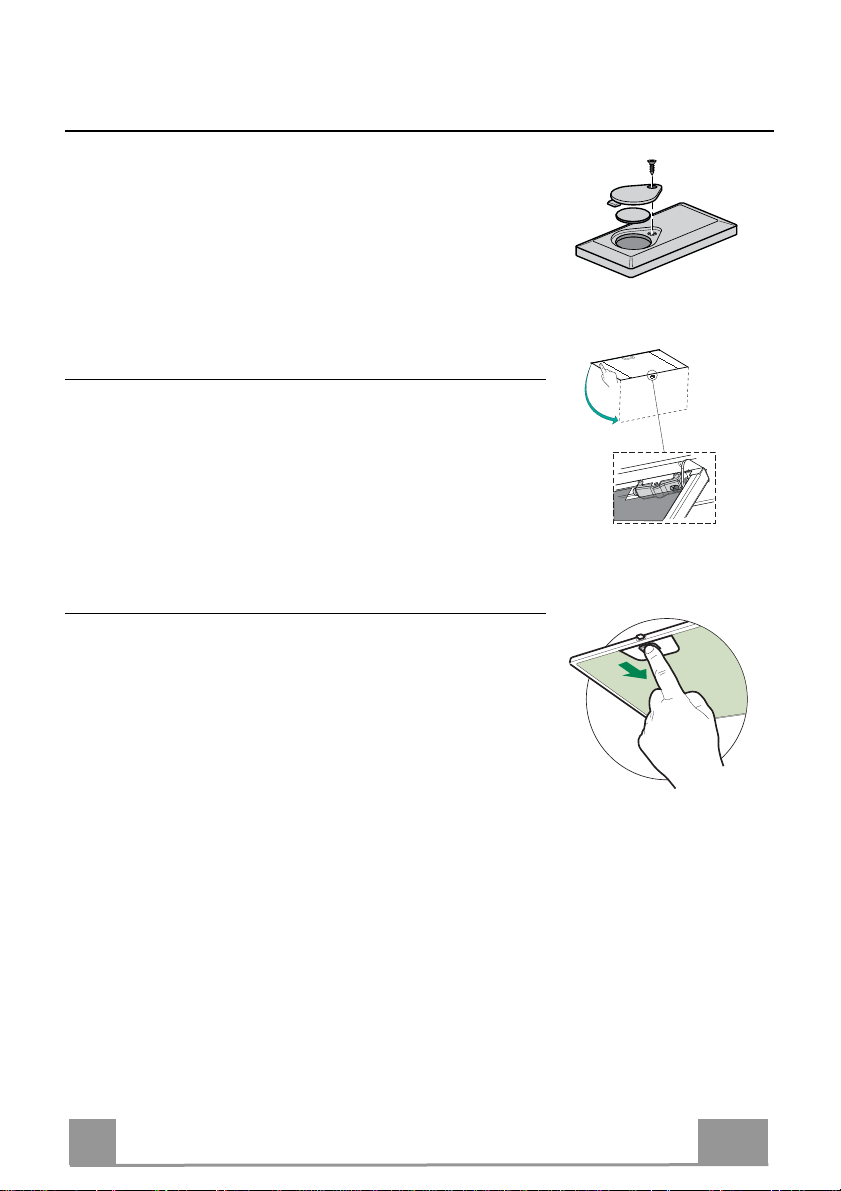
TELECOMANDO (OPZIONALE)
Questo apparecchio può essere comandato per mezzo di un
telecomando, alimentato con una batteria da 3 V del tipo CR2032 (non
inclusa).
• Non riporre il telecomando in prossimità di fonti di calore.
• Non disperdere le pile nell’ambiente, depositarle negli appositi
contenitori.
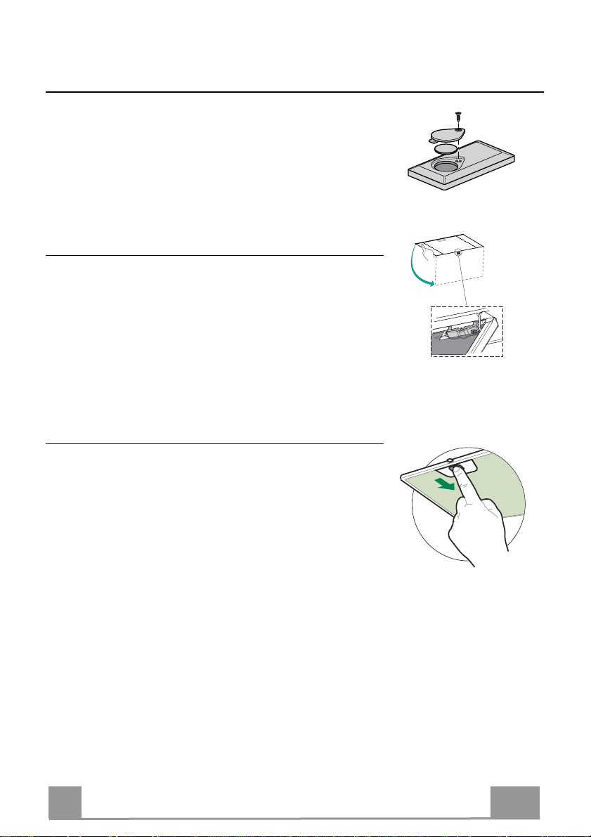
Apertura Pannello
• Aprire il Pannello tirandolo.
• Pulirlo esternamente con un panno umido e detersivo liquido
neutro.
• Pulirlo anche internamente utilizzando un panno umido e detergente neutro; non utilizzare panni o spugne bagnate, né getti
d’acqua; non utilizzare sostanze abrasive.
Filtri antigrasso metallici
Sono lavabili in lavastoviglie, e necessitano di essere lavati quando il Led S1 si accende o almeno ogni 2 mesi circa di utilizzo o
più frequentemente, per un uso particolarmente intenso.
PULIZIA FILTRI
Reset del segnale di allarme
• Spegnere le Luci e il Motore di aspirazione.
• Premere il tasto T3 per almeno 3 secondi, sino al triplo lam-
peggio di conferma del Led.
Pulizia Filtri
• Aprire le Ante.
• Togliere il Filtro spingendolo verso la parte posteriore del
gruppo e tirando contemporaneamente verso il basso.
• Lavare il filtro evitando di piegarlo, e lasciarlo asciugare prima
di rimontarlo (un’eventuale cambiamento del colore della superficie del filtro, che potrebbe verificarsi nel tempo, non pregiudica assolutamente l’efficienza dello stesso).
• Rimontarlo facendo attenzione a mantenere la maniglia verso
la parte visibile esterna.
• Richiudere le Ante.
IT
11
1

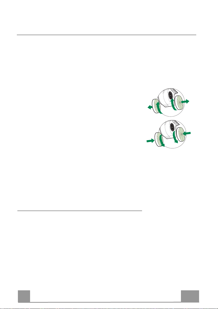
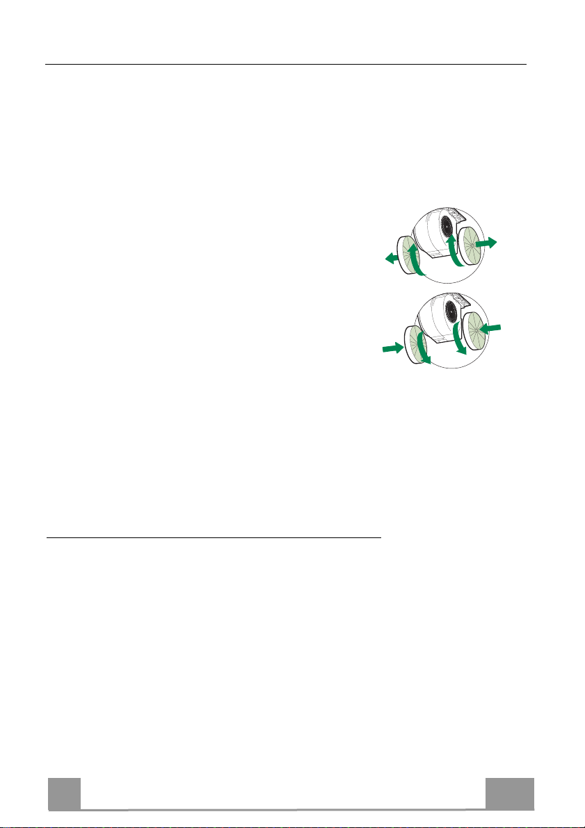
Filtri antiodore al Carbone attivo (Versione Filtrante)
Non è lavabile e non è rigenerabile, va sostituito quando il led S1 lampeggia o almeno ogni 4
mesi. La segnalazione di Allarme, se preventivamente attivata, si verifica solo quando é azionato il Motore di aspirazione.
Attivazione del segnale di allarme
• Nelle Cappe in Versione Filtrante, la segnalazione di Allarme saturazione Filtri va attivata al
momento dell’installazione o successivamente.
• Spegnere le Luci e il Motore di aspirazione.
• Premere per 5 secondi il Tasto T2 sino al doppio lampeggio di conferma del Led.
SOSTITUZIONE
Reset del segnale di allarme
• Spegnere le Luci e il Motore di aspirazione.
• Premere il tasto T3 per almeno 3 secondi, sino al triplo lam-
peggio di conferma del Led.
Sostituzione Filtro
• Aprire le Ante.
• Rimuovere il Filtro antigrasso.
• Rimuovere i Filtri antiodore al Carbone attivo saturi, come indicato (A).
• Montare i nuovi Filtri, come indicato (B).
• Rimontare il Filtro antigrasso.
• Chiudere le Ante.
A
B
Illuminazione
• Per la sostituzione contattare l’Assistenza Tecnica ("Per
l'acquisto rivolgersi all'assistenza tecnica").
IT
12
1
SICHERHEITSINFORMATIONEN
Zu Ihrer eigenen Sicherheit und für die korrekte Funktion des Gerätes
lesen Sie bitte diese Betriebsanleitung aufmerksam durch, bevor Sie das
Gerät installieren und benutzen. Verwahren Sie die Bedienungsanleitung
stets zusammen mit dem Gerät, auch wenn Sie dieses an Dritte
weitergeben oder übertragen. Es ist wichtig, dass der Benutzer alle
Betriebs- und Sicherheitsmerkmale des Gerätes kennt.
Die Kabel müssen von einem zuständigen Fachmann angeschlossen
werden.
Der Hersteller haftet nicht für etwai
Installat
Der min. Sicherheitsabstand zwischen Kochfeld und Abzugshaube
beträgt 650 m
siehe Absatz Installation).
Sollten die Ins
größeren Abs
berücksichtigen.
Sicherstellen, dass die Netzspannung der auf dem Typenschild
angegebenen Spannung entspricht. Das Typenschild ist im Inneren der
Haube angebracht.
Trennv
Verkabelungs
Für Geräte der Klasse I sicherstellen, dass das Versorgungsnetz des
Gebäudes korrekt geerdet ist.
Die Abz
Mindestdurchmesser von 120 mm anschließen. Der Verlauf des
Rauchabzugs muss so kurz wie möglich sein.
Alle gesetzlic
Die Abz
den Rauc
usw.).
ion oder einen ungeeignet
m (einige Modelle können
tallationsanweisungen des gasbetriebenen Kochfe
tand als oben angeg
orrichtungen müssen in der festen Anlage gemä
systeme in
ugshaube an den Schornstein mit einem Ro
hen Vorschriften im Bereich Abluft einhalt
ugshaube darf nicht an einen Schacht angeschlossen we
hgase abgeleitet werden (z. B. von Heizkesseln, Kaminen,
stalliert werden.
ge Schäden, die durch eine fehlerhafte
en Gebrauch entstehen könnten.
auch niedriger installiert werden;
lds einen
eben vorsehen, ist dies zu
ß Normen über
hr mit
en.
rden, in
DE
13
1

Falls die Abzugshaube mit Geräten verwendet wird, die nicht elektrisch
betrieben sind (z.B. Gasgeräte), muss im Raum für eine ausreichende Belüftung
gesorgt werden, damit der Rückfluss der Abgase verhindert wird. Wird die
Abzugshaube zusammen mit nicht elektrisch betriebenen Geräten eingesetzt,
darf der Unterdruck im Raum 0,04 mbar nicht überschreiten, damit die Abgase
nicht wieder angesaugt werden.
Die Luft darf nicht durch einen Kanal abgelassen werden, der als Rauchabzug
für Gasgeräte oder Geräte verwendet wird, die mit anderen Brennstoffen
betrieben werden.
Wenn das Gerätekabel beschädigt ist, muss es vom Hersteller oder von einem
Kundendiensttechniker ersetzt werden.
Den Stecker in eine den einschlägigen Vorschriften entsprechende zugängliche
Steckdose stecken.
Was die technischen und sicherheitsrelevanten Maßnahmen für den
Rauchabzug betrifft, sind die Vorgaben der örtlichen Behörden streng
einzuhalten.
WARNUNG: Bevor die Haube installiert wird, die Schutzfolien abziehen.
Nur für die Abzugshaube geeignete Schrauben und Kleinteile verwenden.
WARNUNG: Die mangelnde Verwendung von Schrauben und
Befestigungselementen gemäß der vorliegenden Anleitung kann zu
Stromschlaggefahr führen.
Nicht direkt mit optischen Instrumenten (Fernglas, Lupe, usw.) in das Licht
schauen.
Auf keinen Fall unter der Haube flambieren: Dabei könnte ein Brand entstehen.
Dieses Gerät darf von Kindern ab 8 Jahren und von Personen mit beschränkten
geistigen, physischen oder sensorischen Fähigkeiten oder mangels Erfahrung
und/oder mangels Wissen benutzt werden, vorausgesetzt, sie werden
aufmerksam beaufsichtigt oder über den sicheren Gebrauch des Geräts und die
damit verbundenen Gefahren eingewiesen. Sicherstellen, dass Kinder nicht mit
dem Gerät spielen. Vom Benutzer auszuführende Reinigungs- und
Wartungsarbeiten dürfen nicht von Kindern ausgeführt werden, sofern sie nicht
dabei beaufsichtigt werden.
Kinder müssen beaufsichtigt werden, damit sichergestellt wird, dass sie nicht am
Gerät spielen.
DE
14
1
Dieses Gerät darf nicht von Personen (einschließlich Kindern) mit
beschränkten geistigen, physischen oder sensorischen Fähigkeiten oder
mangels Erfahrung und/oder mangels Wissen benutzt werden, außer sie
werden aufm
erksam beauf
sichtigt und eingewiesen.
Die frei zugänglichen Teile können während des Kochens mit
Kochgeräten sehr heiß werden.
Die Filter sind nach den angegebenen Intervallen zu reinigen und/oder zu
ersetzen (Brandgefahr). Siehe Absatz Wartung und Reinigung.
Wenn die Abzugshaube gleichzeitig mit Geräten verwendet wird, die Gas
oder andere Brennstoffe benutzen, muss im Raum eine ausreichende
Belüftung vorhanden sein (gilt nic
ht fü
r Geräte, die nur Luft in den Raum
ablassen).
Schutzschild bei Rissbildung ersetzen. Das Symbol am Produkt oder
auf der Verpackung weist darauf hin, das
Hausmüll ent
einer speziellen Samm
abgegeben w
sorgt werden darf. Das ausrangierte Gerät muss vielm
elstelle für elektrische und elek
erden. Mit der vorschri
ftsmäßigen Entsorgung des Gerätes
s das Gerät nicht als norma
tronische Geräte
ler
ehr bei
trägt der Benutzer dazu bei, schädliche Auswirkungen auf Umwelt und
Gesundheit zu vermeiden. Weitere Informationen zum Recycling dieses
Produktes können bei der zuständigen Behörde, der örtlichen
Abfallbes
eitigung oder bei dem Händler, der das Gerät verkauft hat,
eingeholt werden.
DE
15
1
CHARAKTERISTIKEN
Platzbedarf
530 mm530 mm
Komponenten
Bez. Menge Produktkomponenten
1 1 Haubenkörper komplett mit: Bedienelemente, Beleuch-
tung, Filter, Absaugeinheit
2 1 Rahmen
8 1 Luftstromrichtungsgitter
9 1 Reduzierflansch ø 150-120 mm
Bez. Menge Produktkomponenten
12a 10 Schrauben
12e 2 Schrauben 2,9 x 9,5
12f 6 Schrauben 2,9 x 6,5
Menge Unterlagen
1 Betriebsanleitung
DE
12e
8
9
2
12f
1
16
MONTAGE
Montage des Haubenkörpers
BEVOR DIE HAUBE AM HÄNGESCHRANK MONTIERT WIRD, WIE FOLGT VORGEHEN:
• Die Drähte der Bedienelemente abhängen, indem
die Verbinder gelöst werden.
• Die Drähte der Beleuchtung abhängen, indem die
Verbinder gelöst werden.
• Die Haube kann direkt an der Unterseite des
Hängeschranks angebrach
• An der Unterseite des Hängeschranks eine
Aussparung anfertigen, wie abgebildet.
• Die Haube einsetzen und die seitlichen Halterungen
einhaken.
• Mit den 10 mitgelieferten Schrauben 12a
befestigen.
• Durch Festschrauben von unten der Schrauben Vf
definitiv blockieren.
• Das Absaugpaneel herausziehen.
Das Paneel vom
•
Hebel des Befestigungszapfens verschoben wird.
Haubenkörper lösen, in dem der spezielle
t werden min.
13
495 - 675 - 835
260
• Die Fettfilter entfernen.
• Den Rahmen mit den 6
Schrauben 12f wi
befestig
en, die Drähte von
Bedienelementen und
Beleuchtung erneut anschließen,
den Fettfilter einbauen und das
Paneel wieder verschließen.
eder
DE
1
17

Anschluss im Abluftbetrieb
Bei Abluftbetrieb kann die Haube vom Installateur
wahlweise mittels Rohr oder Schlauch (ø 150 oder 120
mm) an die Außenrohrleitung angeschlossen werden.
• Bei Verwendung eines Anschlussrohres ø 120 den
Reduzierflansch 9 am Haubenaustritt anbringen.
• Das Rohr mit geeigneten Rohrschellen fixieren. Das
hierzu erforderliche Material wird nicht mitgeliefert.
• Eventuell vorhandene Aktivkohlefilter entnehmen.
ø 150
ø 120
9
Anschluss im Umluftbetrieb
• In das eventuell über der Haube vorhandene Bord ein
Loch ø 125 mm bohren.
• Den Reduzierflansch 9 am Haubenaustritt anbringen.
• Den Flansch beim Luftaustritt am Bord oberhalb der
Haube mittels Rohr oder Schlauch ø120 mm anschließen.
• Das Rohr mit geeigneten Rohrschellen fixieren. Das
hierzu erforderliche Material wird nicht mitgeliefert.
• Das Luftleitgitter 8 mit Hilfe von 2 der mitgelieferten
Schrauben 12e (2,9 x 9,5) beim Austritt der rückzuführenden Luft fixieren.
• Sicherstellen, dass der Aktivkohle-Geruchsfilter vorhanden ist.
ELEKTROANSCHLUSS
• Bei Anschluss der Haube an das Stromnetz muss ein zweipoliger Schalter mit einem Öffnungsweg von mindestens 3 mm zwischengeschaltet werden.
ø 125
12e
8
9
DE
18
1
BEDIENUNG
L
S1
L
T1 T2 T3 T4
L
T1 T4
T3S1T2
Schalttafel
Taste LED Funktion
L
-
T1
Bleibend Schaltet den Motor bei der ersten Betriebsgeschwindigkeit ein/aus.
T2
Bleibend
T3
Bleibend
T4
Bleibend
S1
Bleibend Meldet den Alarm für Sättigung der Metallfettfilter und die Notwendigkeit,
Blinkend Meldet, sofern aktiviert, den Alarm für Sättigung des Aktivkohlefilters, der
Schaltet die Beleuchtung bei maximaler Intensität ein/aus.
Schaltet den Motor bei der zweiten Betriebsgeschwindigkeit ein.
Mit zirka 5 Sekunden langem Gedrückthalten der Taste bei abgeschalteten
Verbrauchern (Motor+Licht) wird der Alarm für aktive Aktivkohlefilter
aktiviert und die entsprechende LED blinkt zweimal.
Zum Abstellen die Taste erneut 5 Sekunden lang drücken, die entsprechende
LED blinkt ein Mal.
Schaltet den Motor bei der dritten Betriebsgeschwindigkeit ein.
Mit zirka 3 Sekunden langem Gedrückthalten der Taste bei abgeschalteten
Verbrauchern (Motor+Licht) erfolgt ein Reset und die LED S1 blinkt drei Mal.
Schaltet den Motor bei Intensivgeschwindigkeit ein.
Diese Geschwindigkeit ist auf 6 Minuten zeitgeregelt. Nach Ablauf dieser Zeit
kehrt das System zu der zuvor eingestellten Geschwindigkeit zurück. Wird sie
bei abgestelltem Motor aktiviert, wird nach Ablauf der Zeit zum Betriebsmodus
OFF übergegangen.
Mit 5 Sekunden langem Drücken wird die Fernbedienung aktiviert und die
entsprechende LED blinkt zwei Mal.
Mit 5 Sekunden langem Drücken wird die Fernbedienung deaktiviert und die
entsprechende LED blinkt nur ein Mal.
diese zu waschen. Dieser Alarm wird nach 100 effektiven Betriebsstunden der
Abzugshaube ausgelöst.
ausgewechselt werden muss; auch die Metallfettfilter müssen gewaschen
werden. Der Alarm für Sättigung des Aktivkohlefilters wird nach 200
effektiven Betriebsstunden der Abzugshaube ausgelöst.
T1
T2
T3
T4
S1
DE
19
1
REINIGUNG UND WARTUNG
FERNBEDIENUNG (OPTION)
Dieses Gerät kann per Fernbedienung, die mit einer 3V-Batterie vom
Typ CR2032 (nicht mitgeliefert) versorgt wird, bedient werden.
• Die Fernbedienung nicht in der Nähe von Wärmequellen ablegen.
• Altbatterien zum Schutz der Umwelt in Sammelboxen entsorgen.
Öffnen des Paneels
• Das Paneel herausziehen.
• Die Außenflächen mit einem feuchten Lappen und einem
neutralen Flüssigreiniger säubern.
• Auch Innen mit einem feuchten Lappen und einem neutralen
Reinigungsmittel säubern; keine nassen Tücher oder
Schwämme, oder gar Wasser verwenden, und keine
schleifenden Mittel einsetzen.
Metallfettfilter
Die Fettfilter sind spülmaschinengeeignet und müssen gewaschen
werden, sobald sich die LED S1 einschaltet, oder mindestens alle
2 Monate, oder auch öfter, je nach Intensität des Gebrauchs.
REINIGUNG DER FILTER
Reset des Alarmsignals
• Die Beleuchtung und den Absaugmotor abstellen.
• Die Taste T3 mindestens 3 Sekunden lang drücken, bis der
Vorgang durch dreimaliges Blinken der LED bestätigt wird.
Reinigung der Filter
• Die Klappen öffnen.
• Den Filter zu dem hinteren Teil der Gruppe schieben und
gleichzeitig nach unten ziehen.
• Den Filter waschen, ohne ihn zu verbiegen, und vor dem Wiedereinbau trocknen lassen (die Farbe der Filteroberfläche kann
sich mit der Zeit verändern, was aber die Wirksamkeit keinesfalls beeinträchtigt.)
• Nun den Filter wieder einbauen, so dass der Griff zur Aus-
senseite zeigt.
•
Die Klappen wieder schließen.
DE
20
2
Aktivkohle-Geruchsfilter (Umluftvariante)
Der Aktivkohlefilter ist weder waschbar, noch regenerierbar und muss ausgewechselt werden,
wenn die LED S1 blinkt, oder mindestens alle 4 Monate. Die Alarmmeldung, wenn zuvor aktiviert, erfolgt nur, wenn der Absaugmotor zugeschaltet ist.
Aktivierung des Alarmsignals
• Bei der Umluftvariante sollte die Alarmanzeige für die Filtersättigung bei der Erstinbetrieb-
nahme aktiviert werden. Zudem kann sie nachträglich wie folgt aktiviert werden:
• Die Beleuchtung und den Absaugmotor abstellen.
• 5 Sekunden lang die Taste T2 drücken, bis die LED zur Bestätigung blinkt:
AUSWECHSELN
Reset des Alarmsignals
• Die Beleuchtung und den Absaugmotor abstellen.
• Die Taste T3 mindestens 3 Sekunden lang drücken, bis der
Vorgang durch dreimaliges Blinken der LED bestätigt wird.
Auswechseln des Filters
• Die Klappen öffnen.
• Den Fettfilter ausbauen.
• Die verbrauchten Aktivkohle-Geruchsfilter wie angegeben
ausbauen (A).
• Die neuen Filter wie angegeben einbauen (B).
• Den Fettfilter wieder einbauen.
• Die Klappen wieder schließen.
A
B
Beleuchtung
LED-Strahler
• Für den Austausch der LED-Strahler wenden Sie sich bitte an den
Kundendienst.
DE
21
2
SAFETY INFORMATION
For your safety and correct operation of the appliance, read this manual
carefully before installation and use. Always keep these instructions
with the appliance even if you move or sell it. Users must fully know the
operation and safety features of the appliance.
The wire connection has to be done by specialized technician.
The manufacturer will not be held liabl
incorrect or improper installation.
The minimum safety distance between the cooker top and the extractor
hood is 650 mm (some models can be installed at a lower height,
please refer
If the instructions for
distance, this must be respected.
Check that the mains voltage correspon
rating plate fixed to the inside of the hood.
Means for disconnection must be incorporated in the fixed wiring in
accordance with the wiring rules.
For Class I appliances, check that the domestic power supply
guarantees adequate earthing.
Connect the extractor to the exhaust flue through a pipe of minimum
diameter 120 mm. The route of the flue must be as short as possible.
Regulations concerning the discharge of air have to be fulfilled.
Do not connect the extractor hood to exhaust ducts carrying
combustion fumes (boiler
to the paragraphs on work
installation for the gas hob specify a greater
s, fireplaces, etc.).
e for any damages resulting from
ing dimensions and installation).
ds to that i
ndicated on the
EN
22
2
If the extractor is used in conjunction with non-electrical appliances
(e.g. gas bur
ning appliances), a suffi
cient degree of aeration must be
guaranteed in the room in order to prevent the backflow of exhaust gas.
When the cooker hood is used in conjunction with appliances supplied
with energy other than electric, the negative pressure in the room must
not exceed 0,04 mbar to prevent fumes being drawn back into the room
by the cooker hood.
The air must not be discharged into a flue that is used for exhausting
fumes from appliances bur
ning gas or
other fuels.
If the supply cord is damaged, it must be replaced from the manufac-
turer or its service agent.
Connect the plug to a socket complying with current regulations, lo-
cated in an accessible place.
With regards to the technical and safety measures to be adopted for
fume dischar
ging it is important to closely follow the regulations pro-
vided by the local authorities.
WARNING: Before installing the Hood, remove the protective films.
Use only scr
ews and small parts in sup
port of the hood.
WARNING: Failure to install the screws or fixing device in accordance
with these instructions may result in electrical hazards.
Do not look directly at the light through optical devices (binoculars,
magnifying glasses…)
Do not flambè under the r
.
ange hood; risk of fire.
This appliance can be used by children aged from 8 years and above
and persons with reduced physical, sensory or mental capabilities or
lack of experience and knowledge if they have been given supervision
or instruction concerning use of the appliance in a safe way and understand the hazards involved. Children s
hall not play with the appliance.
Cleaning and user maintenance shall not be made by children without
supervision.
Children should be super
vised to ensure
that they do not play with the
appliance.
EN
23
2
The appliance is not to be used by persons (including children) with re-
duced physical, sensory or mental ca
pabilities, or lack of experience
and knowledge, unless they have been given supervision or instruction.
Accessible parts may become hot when used with cooking appliances.
Clean and/or
replace the Filters afte
r the specified time period (Fire
hazard). See paragraph Care and Cleaning.
There shall be adequate ventilation of the room when the range hood is
used at the same time as appliances burning gas or
applicable to appliances that only discharge the air
The symbol
on the product or on its packaging indicates that this
other fuels (
back into the r
not
oom).
product may not be treated as household waste. Instead it shall be
handed over to the applica
trical and electronic equipment. By ens
ble collection point for the recycling of elec-
uring this product is disposed of
correctly, you will help prevent potential negative consequences for the
environment and human health, which could otherwise be caused by
inappropriate waste handling of this product. For
more detailed information about recycling of this product, please contact your local city office
your household waste disposal ser
vice or the shop where you pur-
chased the product.
,
EN
24
2
CHARACTERISTICS
Dimensions
530 mm530 mm
Components
Ref. Q.ty Product Components
1 1 Hood Body, complete with :Controls, Light, Blower,
Filters
2 1 Frame
8 1 Directioned grid
9 1 Reducer Flange ø 150-120 mm
Ref. Q.ty Installation Components
12a 10 Screws
12e 2 Screws 2,9 x 9,5
12f 6 Screws 2,9 x 6,5
Q.ty Documentation
1 Instruction Manual
EN
12e
8
9
2
12f
2
25
INSTALLATION
BEFORE FITTING THE HOOD TO THE WALL UNIT, PROCEED AS FOLLOWS:
Fitting the Hood canopy
• Disconnect the wires to the Commands at the connectors.
• Disconnect the wires to the Light at the connectors.
• The Hood can be installed directly on the
underside of th
• Create an opening in the bottom of the wall
unit, as shown.
• Insert the hood until the side supports snap
into place.
• Fasten using the 10 screws 12a provided.
• Lock in position by tightening the screws Vf
from underneath the hood.
• Open the suction panel by turning
the specific knob.
Disconnect th
•
canopy by sliding the fixing pin
lever.
• Remove grease filters.
e wall unit.
e panel from the hood
13
495 - 675 - 835
260
• Screw the Frame into place
using the 6 screws 12f, reconnect the wires to the
Commands and Light, replace the metal grease filter and the Panel.
EN
26
2

Connections
DUCTED VERSION AIR EXHAUST SYSTEM
When installing the ducted version, connect the hood to
the chimney using either a flexible or rigid pipe ø 150
or 120 mm, the choice of which is left to the installer.
• To install a ø 120 mm air exhaust connection, insert
the reducer flange 9 on the hood body outlet.
• Fix the pipe in position using sufficient pipe clamps
(not supplied).
• Remove possible charcoal filters.
ø 150
ø 120
9
RECIRCULATION VERSION AIR OUTLET
• Cut a hole ø 125 mm in any shelf that may be positioned over the hood.
• Insert the reducer flange 9 on the hood body outlet.
• Connect the flange to the outlet on the shelf over the
hood by using a flexible or rigid pipe ø120 mm.
• Fix the pipe in position using sufficient pipe clamps
(not supplied).
• Fix the air outlet grid 8 on the recirculation air outlet
by using the 2 screws 12e (2,9 x 9,5) provided.
• Ensure that the activated charcoal filters have been
inserted.
ELECTRICAL CONNECTION
• Connect the hood to the mains through a two-pole switch having a contact gap of at least 3
mm..
ø 125
12e
8
9
EN
27
2
USE
L
T1 T2 T3 T4
L
T1 T4
Button Led Function
L
-
T1
Fixed Turns the motor on/off at speed one.
T2
Fixed
T3
Fixed
T4
Fixed
S1
Fixed Signals the Metal Grease Filter saturation alarm, indicating that it is necessary to
Flashing When this is activated, it signals the Activated Charcoal Filter saturation alarm,
Turns the lights on/off at maximum strength.
Turns the Motor on at speed two.
Press and hold the button for approximately 3 seconds, with all the loads turned
off (Motor and Lights), to turn the Activated Charcoal Filter alarm on. The
relevant LED flashes twice to confirm.
To turn the alarm off, press the button again and hold for at least 3 seconds. The
relevant LED flashes once.
Turns the Motor on at speed three.
Press and hold the button for approximately 3 seconds, with all the loads turned
off (Motor and Lights), to perform a reset of Filter saturation alarm. The LED S1
flashes three times.
Turns the Motor on at INTENSIVE Speed.
This speed is timed to run for 6 minutes. At the end of this time, the system
returns automatically to the speed that was set before. If it is activated with the
motor turned off, the hood will switch to OFF at the end of the time.
Press and hold for 3 seconds to enable the remote control, indicated by the LED
flashing twice.
Press and hold for 3 seconds to disable the remote control, indicated by the LED
flashing just once.
wash the filters. The alarm is triggered after the Hood has been in operation for
100 working hours.
indicating that the filter must be changed; the Metal Grease Filters must also be
washed. The Activated Charcoal Filter saturation alarm comes into operation after
the Hood has been working for 200 hours.
L
S1
T3S1T2
T1
T2
T3
T4
S1
Control panel
EN
28
2
CARE AND CLEANING
REMOTE CONTROL (OPTIONAL)
This appliance can be commanded using a remote control, powered by
a CR2032 type 3 V battery (not supplied).
• Do not place the remote control near heat sources.
• Do not discard the batteries with normal waste, they must be put into
the specific containers.
Opening Panel
• Open the Panel by pulling it.
• Clean the outside with a damp cloth and neutral detergent.
• Clean the inside using a damp cloth and neutral detergent; do
not use wet cloths or sponges, or jets of water; do not use
abrasive substances.
Metal grease filters
These can be washed in the dishwasher, and need to be cleaned
whenever the S1 Led comes on or at least once every 2 months
use, or more frequently if use is particularly intensive.
CLEANING THE FILTERS
Resetting the alarm signal
• Turn the Lights and the Suction Motor off.
• Press T3 and hold for at least 3 seconds, until LED flashes
three times in confirmation.
Cleaning the Filters
• Open the doors.
• Remove the Filter, pushing it towards the back of the unit and
at the same time pulling downward.
• Wash the filter without bending it, and leave it to dry thoroughly before replacing (if the surface of the filter changes
colour over time, this will have absolutely no effect on its efficiency).
• Replace, taking care to ensure that the handle faces forwards.
• Close the doors again.
EN
29
2
Activated Charcoal Filter (Recirculation Version)
This cannot be washed or regenerated, and must be changed when led S1 starts to flash, or at
least once every 4 months. The Alarm signal, if it has been activated, only appears when the
Suction motor is turned on.
Activating the alarm signal
• In Recirculation Version Hoods, the Filter Saturation Alarm must be activated on installation or at a later date.
• Turn the Lights and the Suction Motor off.
• Press button T2 and hold it for 5 seconds until the LED flashes twice in confirmation:
CHANGING
Resetting the alarm signal
• Turn the Lights and the Suction Motor off.
• Press T3 and hold for at least 3 seconds, until LED flashes
three times in confirmation.
Changing the Filter
• Open the doors.
• Remove the Metal Grease Filter.
• Remove the saturated Activated Charcoal Filters, as
indicated (A).
• Fit the new Filters, as indicated (B).
• Replace the Metal grease filters.
• Close the doors.
A
B
Lighting unit
• For replacement contact technical support ("To purchase
contact technical support").
EN 30FR

CONSIGNES DE SÉCURITÉ
Pour votre sécurité et pour garantir le fonctionnement correct de
l’appareil, veuillez lire attentivement ce manuel avant d’installer et de
mettre en fonction l’appareil. Toujours conserver ces instructions avec
l’appareil, même en cas de cession ou de transfert à une autre personne.
Il est important que les utilisateurs connaissent toutes les caractéristiques
de fonctionnement et de sécurité de l’appareil.
La connexion des câbles doit être effectuée par un technicien compétent.
En aucun cas le fabricant ne peut être tenu pour responsable d’év
dommages dus à une installation ou à une utilisation impropre.
La distance de sécurit
aspirante est de 650 mm (c
hauteur inf
et l’installation).
Si les instructions d’installation du plan de cuisson à gaz spécifient une
distance supérieure à celle indiquée ci-dessus, veuillez impérativement en
tenir compte.
Assurez
plaque des caractéristiques apposée à l’intérieur de la hotte.
Les dispositifs
conformément aux normes sur les systèmes de câblage.
Pour les appareils de Classe I, s’assurer que l’installation électrique de
votre int
Reliez l’as
minimum de 120 mm. Le parcours des f
possible.
Respecter toutes les norm
Ne reliez pas la hotte aspirante aux conduits de cheminée qui acheminent
les fumées de combustion (par ex. de c
érieure ; voir le paragraphe concernant les
-vous que la tension du secteur corres
de sectionnement doivent être mont
érieur dispose d’une
pirateur du conduit de chemin
é minimum entre le plan de cuiss
ertains m
mise à la terre adéquate.
es concernant l’évacuat
odèles peuvent être installés à une
pond à celle indiquée sur la
ée avec un tube ayant un diamètre
umées doit êt
haudières, de cheminées, et
on et la hotte
dimensions de travail
és dans l’installation fixe
re le plus court
ion de l’air.
entuels
c.).
31
3

Si vous utilisez l’aspirateur en même temps que des appareils non électriques
(par ex. fonctionnant au gaz), veillez à ce que la pièce soit adéquatement
ventilée, afin d’empêcher le retour du flux des gaz d’évacuation. Si vous utilisez
la hotte de cuisine en même temps que des appareils non alimentés à
l’électricité, la pression négative dans la pièce ne doit pas dépasser 0,04 mbar,
afin d’éviter que les fumées soient réaspirées dans la pièce où se trouve la hotte.
Ne pas évacuer l’air à travers une conduite utilisée pour l’évacuation des fumées
des appareils de combustion alimentés au gaz ou avec d’autres combustibles.
Si le cordon d’alimentation est endommagé, faites-le remplacer par le fabricant
ou par un technicien d’un service après-vente agréé.
Branchez la fiche à une prise conforme aux normes en vigueur et dans une
position accessible.
En ce qui concerne les dimensions techniques et de sécurité à adopter pour
l’évacuation des fumées, veuillez vous conformer scrupuleusement aux
règlements établis par les autorités locales.
AVERTISSEMENT : Avant d’installer la hotte, retirer les films de protection.
Utilisez exclusivement des vis et des petites fournitures du type adapté pour la
hotte.
AVERTISSEMENT toute installation de vis et de dispositifs de fixation non
conformes à ces instructions peut entraîner des risques de décharges
électriques.
Ne pas observer directement avec des instruments optiques (jumelles, lentilles
grossissantes...).
Ne flambez pas des mets sous la hotte : sous risque de développer un incendie.
Cet appareil peut être utilisé par des enfants de plus de 8 ans et par des
personnes dont les capacités physiques, sensorielles ou mentales sont
diminuées ou ayant une expérience et des connaissances insuffisantes, pourvu
que ce soit sous la surveillance attentive d’une personne responsable et après
avoir reçu des instructions sur la manière d’utiliser cet appareil en toute sécurité
et sur les dangers que cela comporte. Assurez-vous que les enfants ne jouent
pas avec cet appareil. Le nettoyage et l’entretien de la part de l’utilisateur ne
doivent pas être effectués par des enfants, à moins qu’ils ne soient surveillés.
Surveillez les enfants. S’assurer qu’ils ne jouent pas avec l’appareil.
FR
32
3

Cet appareil n’est pas destiné à être utilisé par des personnes (enfants
compris
) dont les capacit
és physiques, sensorielles ou mentales sont
diminuées ou ayant une expérience et des connaissances insuffisantes, à
moins que celles-ci ne soient attentivem
ent surveillées et instruites.
Les parties accessibles peuvent devenir très chaudes durant l’utilisation
des appareils de cuisson.
Nettoyer et/ou remplacer les filtres après le délai indiqué (danger
endie). Voir le paragraphe Nettoyage et Entretien.
d’inc
Veillez à ce que la pièce bénéficie d’une ventilation adéquate lors
hotte fonctionne en mêm
res combustibles (non applicable au
d’aut
e temps que des appareils uti
x appareils qui évacuent l’air
lisant du gaz ou
que la
uniquement dans la pièce).
Le symbole
marqué sur le produit ou sur son emballage indique que ce
produit ne peut pas être éliminé comme déchet ménager normal. Lorsque
ce produit doit
être éliminé, veuillez le remettre à un c
entre de collecte
prévu pour le recyclage du matériel électrique et électronique. En vous
assurant que cet appareil est éliminé correctement, vous participez à
prévenir des conséquences potentiellement négatives pour l'environnement
et pour la santé, qui risqueraient de se présenter en cas d’élimination
inappropriée. Pour toute information supplémentaire sur le recyclage de ce
produit, contactez votre municipalit
é, votre déchetterie locale ou le m
où vous avez acheté ce produit.
agasin
FR
33
3

CARACTERISTIQUES
Encombrement
530 mm530 mm
Composants
Réf. Q.té Composants de Produit
1 1 Corps Hotte équipé de: Commandes, Lumière, Groupe
Ventilateur, Filtres
2 1 Profil Cadre
8 1 Grille en Direction Sortie Air
9 1 Flasque de Réduction ø 150-120 mm
Réf. Q.té Composants pour l ’installation
12a 10 Vis
12e 2 Vis 2,9 x 9,5
12f 6 Vis 2,9 x 6,5
Q.té Documentation
1 Manuel d’instructions
FR
12e
8
9
2
12f
3
34

INSTALLATION
Montage du corps de hotte
AVANT DE MONTER LA HOTTE DANS L’ARMOIRE MURALE SUIVRE LA MARCHE CI-DESSOUS :
• Débrancher le câblage des commandes en intervenant sur
les connecteurs.
• Débrancher le câblage des lumières en intervenant sur les connecteurs.
• La hotte peut être installée directement sur le plan
inférieur de
• Faire une entaille sur le plan inférieur de l’armoire
murale, de la manière indiquée.
• Insérer la Hotte jusqu’à accrocher les Supports
latéraux par encliquetage.
• Fixer avec 10 vis 12a fournies.
• Bloquer définitivement en serrant les Vis Vf depuis
le bas de la Hotte.
• Ouvrir le panneau en le tirant.
Décrocher
•
lisser le levier du goujon de fixation spécialement prévu.
s armoires murales.
le panneau du corps de la hotte, en faisant cou-
13
495 - 675 - 835
260
• Retirer les filtres à graisse.
• Visser le cadre avec les 6
rebrancher le câ-
vis 12f,
blage des commandes et
lumières, remonter le filtre
à graisse et fermer le panneau.
FR
35
3

Branchements
SORTIE AIR VERSION ASPIRANTE
Pour l’installation en version aspirante, relier la hotte au
tube de sortie au moyen d’un tube rigide ou flexible de
ø 150 ou 120 mm dont le choix est laissé à
l’installateur.
• Pour la liaison avec le tube ø120 mm, insérer la buse
de réduction 9 sur la sortie du corps de la hotte.
• Fixer le tube avec des colliers serre-tube appropriés.
Le matériel nécessaire n’est pas fourni.
• Retirer les filtres anti-odeur à charbon actif
éventuels.
ø 150
ø 120
9
SORTIE AIR VERSION FILTRANTE
• Percer un trou de ø 125 mm. sur l’éventuelle Tablette
qui se trouve au-dessus de la Hotte.
• Insérer le flasque de réduction 9 sur la sortie du corps
de la hotte.
• Connecter la Flasque au trou de sortie sur la Tablette
qui se trouve au-dessus de la Hotte, au moyen d’un
tuyau rigide ou flexible de ø120 mm.
• Fixer le tube par des colliers appropriés. Le matériau
nécessaire n’est pas fourni.
• Fixer la Grille orientée 8 sur la sortie de l’air recyclé
à l’aide de 2 Vis 12e (2,9 x 9,5) fournies avec
l’appareil.
• S’assurer de la présence des filtres anti-odeur au
charbon actif.
BRANCHEMENT ELECTRIQUE
• Brancher la hotte sur le secteur en interposant un interrupteur bipolaire avec ouverture des
contacts d’au moins 3 mm.
ø 125
12e
8
9
FR
36
3

UTILISATION
L
T1 T2 T3 T4
L
T1 T4
Touche Led Fonction
L
- Allume/Éteint les lumières à la luminosité maximum.
T1
Fixe Démarre/Coupe le moteur à la première vitesse.
T2
Fixe
T3
Fixe
T4
Fixe
S1
Fixe Signale l’alarme saturation filtres à graisse métalliques et la nécessité de les
Clignotante Lorsque l’alarme de saturation du filtre anti-odeur est activée, c’est l’indice que
Démarre le moteur à la deuxième vitesse.
Garder la touche appuyée pendant environ 5 secondes, lorsque toutes les
charges sont éteintes (Moteur+ Éclairage), l’alarme des filtres au charbon actif
s’active et la led correspondante clignotera 2 fois.
Pour la désactiver, appuyer de nouveau sur la touche pendant 5 secondes. La
led correspondante clignotera 1 fois.
Démarre le moteur à la troisième vitesse.
Garder la touche appuyée pendant environ 3 secondes, lorsque toutes les
charges sont éteintes (Moteur+ Éclairage), le reset est effectué et la led S1
correspondante clignotera 3 fois.
Démarre le moteur à la vitesse INTENSIVE.
Cette vitesse est temporisée à 6 minutes. Après ce délai, Le système retourne
automatiquement à la vitesse sélectionnée. Si activée avec le moteur à l’arrêt, à
la fin du délai le système passe en mode OFF.
Garder la touche appuyée pendant environ 5 secondes pour valider la
télécommande. La led correspondante clignotera 2 fois.
Garder la touche appuyée pendant 5 secondes pour invalider la télécommande.
La led correspondante clignotera 1 seule fois
laver. L’alarme entre en fonction après 100 heures de travail effectif de la hotte.
le filtre doit être remplacé. Laver aussi les filtres à graisse métalliques.
L’alarme de saturation filtre anti-odeur au charbon actif entre en fonction après
200 heures de travail effectif de la hotte.
S1
T3S1T2
Tableau de commande
L
T1
T2
T3
T4
S1
FR
37
3

NETTOYAGE ET ENTRETIEN
TÉLÉCOMMANDE (OPTION)
Cet appareil peut être commandé via une télécommande, alimentée
avec une batterie 3 V type CR2032 (non fournie).
• Ne pas ranger la commande à proximité de sources de chaleur.
• Ne pas jeter les batteries dans la nature, mais les déposer dans les
bornes de collecte.
Ouverture panneau
• Ouvrir le panneau en le tirant.
• Le nettoyer à l’extérieur avec un chiffon humide et un
détergent liquide neutre.
• Le nettoyer également à l’intérieur avec un chiffon humide et
un détergent neutre ; ne jamais utiliser des chiffons ou des
éponges mouillés, ni des jets d’eau ; ne pas utiliser de substances abrasives.
Filtres à graisse métalliques
Ils peuvent être lavés au lave-vaisselle et doivent être lavés quand
la led S1 s’allume ou au moins tous les 2 mois d’utilisation ou
plus fréquemment en cas d’utilisation particulièrement intensive.
NETTOYAGE FILTRES
Reset du signal d'alarme
• Éteindre les lumières et le moteur d’aspiration.
• Appuyer sur la touche T3 pendant au moins 3 secondes
jusqu’au triple clignotement de confirmation de la led.
Nettoyage filtres
• Ouvrir les portes
• Retirer le filtre en le poussant vers l’arrière du groupe et en
tirant en même temps vers le bas.
• Laver le filtre en évitant de le plier, et le laisser sécher avant de
le remonter (tout changement de couleur de la surface du filtre,
susceptible de se produire avec le temps, ne nuit en rien à
l’efficacité de ce dernier).
• Le remonter en faisant attention de garder la poignée vers la
partie visible externe.
• Refermer les portes.
FR
38
3

Filtres anti-odeur à charbon actif (version filtrante)
Il n’est ni lavable, ni régénérable. Le remplacer lorsque la led S1 clignote ou au moins tous les
4 mois. Le signal d’alarme, si préalablement activé, se vérifie seulement lorsque le moteur
d’aspiration est en marche.
Activation du signal d’alarme
• Dans les hottes en version filtrante, activer le signal d’alarme de saturation filtres au
moment de l’installation ou après.
• Éteindre les lumières et le moteur d’aspiration.
• Appuyer pendant 5 secondes sur la touche T2 jusqu’à ce que la led de confirmation
clignote :
REMPLACEMENT
Reset du signal d'alarme
• Éteindre les lumières et le moteur d’aspiration.
• Appuyer sur la touche T3 pendant au moins 3 secondes
jusqu’au triple clignotement de confirmation de la led.
Remplacement du filtre
• Ouvrir les portes
• Retirer le filtre à graisse
• Enlever les filtres anti-odeur au charbon actif saturés, comme
indiqué (A).
• Monter les nouveaux filtres, comme indiqué (B).
• Remonter le filtre à graisse
• Refermer les portes.
A
B
Éclairage
• Pour le remplacement, contacter le Service après-vente (« Pour
l’achat, s’adresser au service après-vente »).
FR
39
3

VEILIGHEIDSINFORMATIE
Lees voor uw eigen veiligheid en voor een correcte werking van het appa-
raat eerst deze handleiding aandachtig door, alvorens het apparaat te installeren en te gebruiken. Bewaar deze instructies altijd bij het apparaat,
ook wanneer u het verkoopt of overdraagt aan derden. Gebruikers moeten volledig op de hoogte zijn van de werking en de veiligheidsfuncties
van het apparaat.
De kabels moeten door een ervaren monteur worden aangesloten.
De fabrikant is niet aansprakelijk
een onjuiste installat
De minim
650 mm (som
geïnstalleerd; zie de paragraaf over de werkafmetingen en de installatie).
Als de installatievoorschriften van de gaskookplaat bepalen dat een grote-
re afstand in acht moet worden genomen dan hierbov
dan moet daar rekening mee worden gehouden.
Controleer of de netspanning overeenstemt met de spanning die op het
typeplaatje aan de binnenk
Er moet
overeenstem
Controleer voor apparaten van klasse I of het elektriciteitsnet in uw
woning over een goede aarding beschikt.
Sluit de afzuigkap op het rookkanaal aan met een
diamet
afleggen.
Alle regels voor de luchtafv
Sluit de afzuigkap niet op rookkanalen aan die verbrandingsgassen
afvoeren (bijv.
ale veiligheidsafstand tussen
mige modellen kunnen op een kleinere
en lastscheiders in de vaste installatie worden
ming met de normen over bedradingssy
er van 120 mm. De rook moet
van verwarming
oneigenlijk gebruik.
ie of
voor eventuele schade als gevolg van
de kookplaat en de afzuigkap is
afstand worden
en is aangegeven,
ant van de af
oer moeten in acht worden genom
sketels, open haarden, enz.).
zuigkap staat vermeld.
geïnstalleerd in
stemen.
pijp met een minimale
een zo kort mogelijk traject
en.
NL
40
4

Als de afzuigkap in combinatie met niet-elektrische apparaten wordt gebruikt
pp
(bijv. gasapparaten)
voor
komen dat de uitgestoten gassen terugstr
in combinatie met niet-elektr
onderdruk in het ver
, moet het vertrek voldoende gev
ische apparaten wordt gebr
trek niet groter zijn dan 0,04 mbar om te voor
entileerd zijn om te
omen. Wanneer de afzuigkap
uikt, mag de
komen dat
de damp opnieuw door de afzuigkap in het vertrek gezogen wordt.
De lucht mag niet worden afgevoer
de rookgasafvoer door apparaten op gas of an
voor
d door een k
anaal dat wordt gebruikt
dere brandstoffen.
Een beschadigde voedingskabel moet door de fabrikant of door een
monteur
van de technische servicedienst worden verv
angen.
Sluit de stekker op een toegankelijk stopcontact aan dat voldoet aan de
geldende normen.
Met betrekking tot de technische en veiligheidsmaatregelen voor de
rookgasafvoer
is het belangrijk dat de regels die door de lokale
autoriteiten
zijn bepaald nauwgezet worden opgevolgd.
WAARSCHUWING: verwijder de beschermfolie alvorens de afzuigkap te
installeren.
Gebruik alleen schroeven en kleine onder
delen die
geschikt zijn voor de
afzuigkap.
WAARSCHUWING: indien de schroeven of bevestigingssystemen niet
volgens deze aanwijzingen worden geïnstalleerd, bestaat het gevaar voor
elektrische schokken.
Niet dir
ect met optische instrumenten (verrekijker, vergrootglas…)
waarnemen.
Er mag niet onder de afzuigkap geflambeerd worden: br
Het apparaat mag worden gebruikt door
kinderen ouder
andgevaar
.
dan 8 jaar en door
personen met een lichamelijke, zintuiglijke of geestelijke beperking of met
onvoldoende ervaring en kennis, mits ze onder toezicht staan en goed
geïnstr
ueerd zijn over een veilig gebruik van het apparaat en de gevar
ermee samenhangen. Zorg ervoor
spelen. Reiniging en onderhoud door de gebruiker
dat kinderen
niet met het apparaat
mogen niet door
en die
kinderen
worden uitgevoerd, tenzij ze onder toezicht staan.
Kinderen moeten wor
met het a
araat spelen.
den gecontroleerd om er zeker van te
zijn dat ze niet
NL
41
4

Het apparaat mag niet gebruikt worden door personen (waaronder
kinderen) met
geestelijke, lichamelijke of
zintuiglijke beperkingen, of door
personen zonder ervaring en kennis, tenzij ze onder toezicht staan of
worden geïns
trueerd over
het gebruik van het apparaat.
Tijdens het gebruik van de kooktoestellen kunnen de toegankelijke delen
erg heet worden.
Reinig en/of v
ervang de filter
s na de aangegeven tijdsperiode
(brandgevaar). Zie de paragraaf Onderhoud en reiniging.
De ruimt
e moet voldoende geventileerd z
ijn als de afzuigkap tegelijk met
apparaten op gas of andere brandstoffen wordt gebruikt (niet van
toepassing op apparaten die alleen lucht in de ruimte blazen).
Het symbool
product niet als huishoudafv
op het product of op de verpakking wijst erop dat dit
al mag worden behandeld. Het moet echt
naar een speciaal verzamelcentrum worden gebracht waar elektrische en
elektronische apparatuur wordt gerecycled. Als u ervoor zorgt dat dit
product op de correcte m
anier wordt verw
ijderd, voorkomt u mogelijk voor
mens en milieu negatieve gevolgen die zich zouden kunnen voordoen in
geval van verkeerde afvalbehandeling. Neem voor meer details over het
recyclen van dit product contact op met uw gemeente, de plaatselijke
vuilophaaldienst of de wink
el wa
ar u het product hebt gekocht.
er
NL
42
4

EIGENSCHAPPEN
Buitenafmetingen
530 mm530 mm
Onderdelen
Ref. Aantal Productonderdelen
1 1 Afzuigkap met: Bedieningen, verlichting, filters,
afzuigunit.
2 1 Lijst
8 1 Richtingsrooster
9 1 Verloopflens ø 150-120 mm
Ref. Aantal Installatieonderdelen
12a 10 Schroeven
12e 2 Schroeven 2,9 x 9,5
12f 6 Schroeven 2,9 x 6,5
Aantal Documentatie
1 Instructieboekje
NL
12e
8
9
2
12f
4
43

INSTALLATIE
Montage van de afzuigkap
GA ALS VOLGT TE WERK VOORDAT U DE AFZUIGKAP AAN DE KEUKENKAST MONTEERT:
• Koppel de bedrading van de bedieningstoetsen los door
de stekkers los te maken.
• Koppel de bedrading van de verlichting los door de
stekkers los te maken.
• De afzuigkap kan rechtstreeks op het onderste blad van de
keukenkast worden gemonteerd.
• Bouw het apparaat op het onderste blad van de keukenkast
in volgens de beschrijving.
• Plaats de afzuigkap tot deze vasthaakt op de zijsteunen met
klikbevestiging.
• Bevestig hem met 10 bijgeleverde schroeven 12a.
•
Blokkeer de afzuigkap definitief door de schroeven
Vf vanaf de onderkant van de afzuigkap aan te
draaien.
• T
rek het afzuigpaneel open.
• Koppel het paneel los van de afzuigkap door de hendel van de
bevestigingspen te verschuiven.
495 - 675 - 835
260
13
• Verwijder de vetfilters.
• Schroef de lijst weer vast met
de 6 schroeven
12f, sluit de
bedrading van de
bedieningstoetsen en de
verlichting weer aan,
monteer het vetfilter en het
paneel weer.
NL
44
4

Aansluitingen
LUCHTUITLAAT AFZUIGVERSIE
Bij installatie in afzuigversie, moet u de wasemkap met
de uitlaatleiding verbinden door middel van een starre
of buigzame leiding van ø 150 of 120 mm, naar keuze
van de installateur.
• Voor verbinding met een leiding van ø120 mm, moet
de reductieflens 9 op de uitlaat van de wasemkap
worden aangebracht.
• Zet de leiding vast met geschikt leidingklemmen. Het
benodigde materiaal wordt niet bij de wasemkap geleverd.
• Verwijder de eventuele geurfilters met actieve koolstof.
ø 150
ø 120
9
ø 125
12e
8
9
LUCHTUITLAAT FILTERVERSIE
• Boor een gat van ø 125 mm in de eventuele plank
boven de kap.
• Breng de reductieflens 9 op de uitlaat van de wasemkap aan.
• Verbind de flens met de uitlaatopening op de plank
boven de kap met behulp van een starre of flexibele
leiding van ø120 mm.
• Zet de leiding vast met geschikte leidingklemmen.
Het benodigde materiaal wordt niet bij de wasemkap
geleverd.
• Bevestig het richtingsrooster 8 op de uitlaat van de
gerecirculeerde lucht met 2 van de bijgeleverde
schroeven 12e (2,9 x 9,5).
• Verzeker u ervan dat het geurfilter met actieve
koolstof geïnstalleerd is.
ELEKTRISCHE AANSLUITING
• Sluit de wasemkap aan op de netspanning met een tweepolige schakelaar ertussen met een
opening tussen de contacten van tenminste 3 mm.
NL
45
4

GEBRUIK
L
S1
L
T1 T2 T3 T4
L
T1 T4
T3S1T2
Bedieningspaneel
Toets Led Functie
- Schakelt de lichten op de hoogste lichtsterkte in/uit.
L
Vast Schakelt de motor op de eerste snelheid in/uit.
T1
Vast
T2
Vast
T3
Vast
T4
Vast Signaleert de verzadiging van de metalen vetfilters en het feit dat ze gewassen moeten
S1
Knipperend Indien actief, signaleert deze led het alarm van de verzadiging van het geurfilter met ac-
Schakelt de motor op de tweede snelheid in.
Als de toets ongeveer 5 seconden ingedrukt wordt gehouden als alle belastingen (mo-
tor+lamp) uitgeschakeld zijn, dan wordt het alarm van de actieve koolstoffilters ingeschakeld en knippert de bijbehorende led twee keer.
Houd de toets nog eens 5 seconden ingedrukt om het alarm uit te schakelen. De bijbehorende led knippert één keer.
Schakelt de motor op de derde snelheid in.
Als de toets ongeveer 3 seconden ingedrukt wordt gehouden als alle belastingen uit zijn
(motor+lamp), dan wordt de reset uitgevoerd. De led S1 knippert drie keer.
Schakelt de motor op de HOGE snelheid in.
Deze snelheid is ingesteld op 6 minuten. Na deze periode keert het systeem automatisch
terug naar de eerder gekozen snelheid. Als deze functie bij uitgeschakelde motor wordt
geactiveerd, wordt de afzuigkap na deze periode in de OFF-stand gezet.
Door deze toets 5 seconden ingedrukt te houden wordt de afstandsbediening ingeschakeld. De led knippert twee keer.
Als de toets 5 seconden ingedrukt wordt gehouden, wordt de afstandsbediening uitgeschakeld. De bijbehorende led knippert slechts één keer.
worden. Het alarm wordt na 100 bedrijfsuren van de afzuigkap ingeschakeld.
tieve koolstof dat moet worden vervangen en ook de metalen vetfilters moeten worden
gewassen. Het alarm van de verzadiging van het geurfilter met actieve koolstof wordt na
200 effectieve werkuren van de afzuigkap ingeschakeld.
T1
T2
T3
T4
S1
NL
46
4

REINIGING EN ONDERHOUD
AFSTANDSBEDIENING (OPTIE)
Dit apparaat kan worden bediend met een afstandsbediening, gevoed
met een 3 V CR2032-batterij (niet inbegrepen).
• Plaats de afstandsbediening niet in de buurt van warmtebronnen.
• Laat de batterijen niet in het milieu terechtkomen. Werp ze in
daarvoor bestemde containers.
Openen van het paneel
• Trek het paneel open.
• Reinig het aan de buitenkant met een vochtige doek en een
neutraal vloeibaar schoonmaakmiddel.
• Reinig het ook aan de binnenkant met behulp van een vochtige
doek en een neutraal schoonmaakmiddel; gebruik geen natte
doeken of sponzen of waterstralen; gebruik geen
schuurmiddelen.
Metalen vetfilters
De vetfilters kunnen in de vaatwasser worden gewassen. Dit moet
gebeuren als de led S1 gaat branden of in elk geval ongeveer om
de 2 maanden of vaker bij veelvuldig gebruik.
REINIGEN VAN DE FILTERS
Reset van het alarmsignaal
• Schakel de lampen en de zuigmotor uit.
• Druk minstens 3 seconden op de toets T3 totdat de led ter bevestiging drie maal gaat knipperen.
Reinigen van de filters
• Open de panelen.
• Verwijder het filter door het naar de achterkant van de unit te
duwen en het tegelijkertijd naar beneden te trekken.
• Was het filter zonder het te buigen en laat het drogen alvorens
het weer te monteren (een eventuele kleurverandering van het
filteroppervlak die zich in de loop van de tijd kan voordoen
heeft geen nadelige gevolgen voor de efficiëntie van het filter).
• Monteer het filter weer en houd de handgreep daarbij naar het
zichtbare deel aan de buitenkant.
• Sluit de panelen weer.
NL
47
4

Geurfilters met actieve koolstof (Model met luchtcirculatie)
Dit filter is niet afwasbaar en niet regenereerbaar en moet worden vervangen als de led S1
knippert of in elk geval om de 4 maanden. Het alarm, mits vooraf geactiveerd, wordt alleen
gesignaleerd als de zuigmotor ingeschakeld is.
Activering van het alarmsignaal
• Bij afzuigkappen met luchtcirculatie moet het alarmsignaal ten teken dat de filters verzadigd
zijn geactiveerd worden op het moment van de installatie of daarna.
• Schakel de lampen en de zuigmotor uit.
• Druk 5 seconden op de toets T2 totdat de led ter bevestiging twee maal gaat knipperen.
VERVANGING
Reset van het alarmsignaal
• Schakel de lampen en de zuigmotor uit.
• Druk minstens 3 seconden op de toets T3 totdat de led ter bevestiging drie maal gaat knipperen.
Vervangen van het filter
• Open de panelen.
• Verwijder het vetfilter.
• Verwijder de verzadigde geurfilters met actieve koolstof zoals
aangegeven (A).
• Monteer de nieuwe filters zoals aangegeven (B).
• Monteer het vetfilter weer.
• Sluit de panelen.
A
B
Verlichting
• Neem voor de vervanging contact op met de klantenservice
(‘Wend u voor de aankoop tot de klantenservice’).
NL
48
4

INFORMACIÓN DE SEGURIDAD
Por su propia seguridad y para el correcto funcionamiento del aparato,
lea atentamente este manual antes de la instalación y puesta en marcha. Guarde siempre estas instrucciones con el aparato, incluso si se
cede o transfiere a un tercero. Es importante que los usuarios estén
familiarizados con todas las características de funcionamiento y seguridad del aparato.
Los cables deben ser conectados por un técnico competente.
El fabricante no se hace respons
able de ningún daño que resulte de una
instalación o uso inadecuado.
La distancia mínima de seguridad entre la placa de cocción y la campana extractora es de 650 mm (algunos modelos pueden instalar
altura inferior
ción).
Si en las instrucciones de montaje de la placa de cocción a gas se indica
una distancia mayor
; véase la sección sobre dimensiones de trabajo e instala-
que la indic
ada anteriormente, debe tenerse en
se a una
cuenta.
Compruebe que la tensión de red coincide con la indicada en la placa de
características del interior de la campana.
Los dispositivos de desconexión deben instalarse en la instalación fija de
acuerdo con las regulaciones para sistemas de cableado.
Para los aparatos de la clase I, compruebe que el suministro de corriente
eléctrica de la casa tiene una conexión a tierra adecuada.
Conecte la campana a la chimenea con un tubo de un diámetro mínimo de
120 mm. El trayecto de humos debe ser lo más corto posible.
Deben observarse todas las normas relativas al escape de aire.
No conecte la campana extractora a los conductos de humos de combustión
(p. ej. calderas, chimeneas, etc.).
ES
49
4

Si la campana se utiliza en combinación con equipos no eléctricos (por
ejemplo, apar
en el local par
campana extr
atos de gas), debe asegurarse un grado suficiente
a evitar el retorno del flujo de gases de escape.
actora se utiliza en combinación con apar
presión negativa en el local no debe ser
atos no eléctricos, la
superior a 0,04 mbar
de ventilación
Cuando la
para evitar que
los humos vuelvan al local a través de la campana extractora.
El aire no debe descargar
se a través de un conducto util
izado para los gases
de combustión procedentes de aparatos de combustión de gas u otros
combustibles.
Si el cable de alimentación está dañado, debe ser
reem
plazado por el
fabricante o por un técnico de servicio.
Conecte la clavija a una toma de corriente que cumpla la normativa vigente y
sea
accesible.
En cuanto a las medidas técnicas y de seguridad a adoptar para el vert
humos, es importante cumplir escr
upulosamente las normas establecidas por
ido de
las autoridades locales.
ADVERTENCIA: Retire la película protectora antes de instalar la campana.
Utilice únicamente tornillos y herramientas que sean adecuados para la
campana.
ADVERTENCIA: Si no se instalan tornillos o sujetadores de acuerdo con
estas instr
ucciones, se puede producir una descar
ga eléctrica.
No obser
No cocine en flambeado bajo la campana: podría
Este aparato puede ser
personas con capacidades psico-físico-sensoriales redu
var directamente con instrumentos ópticos (prismáticos, lupas, etc.).
producirse un incendio.
utilizado por niños a partir de los 8 años y por
cidas o con una
experiencia y conocimientos insuficientes, siempre que sean cuidadosamente
super
visados e instruidos sobre cómo utilizar el aparato de forma segur
sobre los peligros que conlleva. A
segúrese de que lo
aparato. La limpieza y el mantenimiento por par
llevados a cabo por
niños, a menos que sean super
s niños no jueguen con el
te del usuar
io no deben ser
visados.
Supervise a los niños, asegurándose de que no jueguen con el aparato.
ES
a y
50
5

El aparato no debe ser utilizado por personas (incluyendo niños) con
capacidades psico-físico-s
conocimientos insuficientes,
ensoriales reducidas o con experiencia y
a menos que sean cuidadosamente
supervisados e instruidos.
Las piezas accesibles pueden calentarse mucho cuando se utilizan
aparatos de cocina.
Limpie y/o reemplace los filtros después del tiempo es
incendio). Véase el apart
Deberá preverse una v
ado Mantenimiento y limpiez
entilación ad
ecuada en el espacio cuando la
pecificado (peligro de
a.
campana extractora de humos se utilice junto con aparatos que utilicen gas
u otros combustibles (no aplicable a
los aparatos que sólo descargan aire
en el local).
El símbolo
debe desecharse como residuo doméstico norm
producto a eliminar debe recogers
para el reciclaje de com
que este producto se desec
en el producto o en su embalaje indica que este producto no
a que el
uado
e en un punto de recogida adec
ponentes eléctric
he correctam
al. Tenga en cuent
os y electrónicos. Al asegurarse de
ente, ayudará a evitar las posibles
consecuencias negativas para el medio ambiente y la salud que podrían
derivarse de una eliminación inadecuada de este producto. Para obtener
inform
ación más detallada sobre el reci
contacto con el Municipio, el serv
claje de este producto, póngase en
icio local de eliminac
ión de residuos o la
tienda donde adquirió el producto.
ES
51
5

CARACTERÍSTICAS
Dimensiones
530 mm530 mm
Componentes
Ref. Cant Componentes del producto
1 1 Cuerpo campana dotado de: Mandos, luz, filtros, grupo
aspirador.
2 1 Marco
8 1 Rejilla direccionada
9 1 Brida de reducción ø 150-120 mm
Ref. Cant Componentes de instalación
12a 10 Tornillos
12e 2 Tornillos 2,9 x 9,5
12f 6 Tornillos 2,9 x 6,5
Cant Documentación
1 Manual de instrucciones
ES
12e
8
9
2
12f
5
52

INSTALACIÓN
Montaje del cuerpo de la campana
ANTES DE MONTAR LA CAMPANA EN EL ARMARIO DE PARED, PROCEDA DE LA SIGUIENTE
MANERA:
• Desconectar los cables de los mandos mediante los conectores.
•
Desconectar los cables de las luces mediante
los conectores.
• La campana se puede instalar directamente en el
plano inferior de los armarios de pared.
• Hacer una abertura en el plano inferior del armario
de pared, como se muestra.
• Introducir la Cmpana hasta enganchar los soportes
laterales de accionamento.
• Fijar con 10 tornillos 12a prporcionados.
• Bloquear définitivamente apretando los tornillos Vf
desde bajo de la Campana.
495 - 675 - 835
260
13
• Abra el panel de aspiraciòn
• Desenganchar el panel del cuerpo de la Campana haciendo
deslizar la leva especìfica del perno de fijaciòn.
• Quitar los filtros antigrasa.
• Atornillar el marco con los
llos 12f, volcer a
6 torni
conectar el cableado de los
mandos y las luces, reemplazar el filtro antigrasa y
el panel.
tirando de èl.
ES
53
5

Conexiones
SALIDA DEL AIRE VERSIÓN ASPIRANTE
Para la instalación de la versión aspirante, conectar la
campana al tubo de salida mediante un tubo rígido o
flexible de ø150 o 120 mm, a discreción del instalador.
• Para la conexión con el tubo de ø120 mm, introducir la
brida de reducción 9 en la salida del cuerpo de la campana.
• Fijar el tubo con abrazaderas adecuadas. Este material no se proporciona en dotación.
• Quitar los filtros antiolor al carbón activo.
ø 150
ø 120
9
SALIDA DEL AIRE VERSIÓN FILTRANTE
• Realizar un orificio de ø 125 mm en la repisa de encima de la campana.
• Introducir la brida de reducción 9 en la salida del
cuerpo de la campana.
• Conectar la salida del cuerpo de la campana con la
parte superior del mueble colgante mediante un tubo
rígido o flexible de ø120 mm, a discreción del instalador.
• Fijar el tubo con abrazaderas adecuadas. Este material no se proporciona en dotación.
• Fijar la rejilla de dirección 8 en la salida del aire reciclado mediante los 2 tornillos 12e (2,9 x 9,5) en dotación.
• Controlar que estén presentes los Filtros Antiolor al
Carbón activo.
CONEXIÓN ELÉCTRICA
• Conectar la campana a la red de alimentación eléctrica instalando un interruptor bipolar con
apertura de los contactos de 3 mm como mínimo.
ø 125
12e
8
9
ES
54
5

USO
L
S1
L
T1 T2 T3 T4
L
T1 T4
T3S1T2
Tablero de mandos
Tecla Led Función
L
-
T1
Fijo E
T2
Fijo
T3
Fijo
T4
Fijo
S1
Fijo Señala la alarma de saturación filtros antigrasa metálicos y la necesidad de
Intermitente
Enciende/Apaga las luces a la máxima velocidad.
nciende/Apaga el motor a la primera velocidad
Enciende el motor a la segunda velocidad.
Manteniendo presionada la tecla por aproximadamente 5 segundos, cuando todas
las cargas están apagadas (Motor+Luz) se activa la alarma de los filtros al
carbono activo visualizando un doble parpadeo del led correspondiente.
Para desactivarlo, se presiona de nuevo la tecla por otros 5 segundos visualizando
un parpadeo simple del led correspondiente.
Enciende el motor a la tercera velocidad.
Manteniendo presionada la tecla por aproximadamente 3 segundos, cuando todas
las cargas están apagadas (Motor+Luz) se efectúa el reset visualizando el triple
parpadeo del led S1.
Enciende el motor a la velocidad INTENSIVA.
Esta velocidad está temporizada en 6 minutos. Una vez terminado el tiempo, el
sistema vuelve automáticamente a la velocidad seleccionada precedentemente. Si
se activa desde motor apagado una vez terminado el tiempo pasa a la modalidad
OFF.
Manteniendo presionada por 5 segundos se habilita el telemando visualizando un
doble parpadeo del mismo led.
Manteniendo presionada la tecla por 5 segundos se deshabilita el telemando
visualizando el parpadeo del led correspondiente una sola vez.
lavarlos. La alarma entra en función después de 100 horas de trabajo efectivo de
la campana.
Señala, cuando está activada, la alarma de saturación filtro antiolor al carbono
activo que debe ser sustituido;deben lavarse además los filtros antigrasa
metálicos. La alarma de saturación filtro antiolor al carbono activo entra en
función después de 200 horas de trabajo efectivo de la campana.
T1
T2
T3
T4
S1
ES
55
5

LIMPIEZA Y MANTENIMIENTO
MANDO REMOTO (OPCIONAL)
Esta unidad puede ser controlada por medio de un mando remoto,
alimentado por una batería de 3 V tipo CR2032 (no incluida).
• No coloque el mando remoto cerca de fuentes de calor.
• No abandone las baterías en el medio ambiente, deposítelas en los
contenedores previstos.
Apertura panel
• Abrir el panel tirándolo.
• Limpiarlo externamente con un paño húmedo y detergente
líquido neutro.
• Limpiarlo también internamente utilizando un paño húmedo y
detergente neutro; no utilizar paños o esponjas mojadas, ni
chorros de agua, no utilizar sustancias abrasivas.
Filtros antigrasa metálicos
Se pueden lavar en lavavajilla, y necesitan ser lavados cuando el
led S1 se enciende o almenos cada 2 meses de uso aproximadamente o más frecuentemente, para un uso particularmente intenso.
LIMPIEZA DE LOS FILTROS
Reset de la señal de alarma
• Apagar las luces y el motor de aspiración.
• Presionar la tecla T3 por almenos 3 segundos, hasta el triple
parpadeo de confirmación del led.
Limpieza de los filtros
• Abrir las puertas.
• Quitar el filtro empujándolo hacia la parte posterior del grupo y
tirando simultáneamente hacia abajo.
• Lavar el filtro evitando doblarlo y dejarlo secar antes de volverlo a montar (un eventual cambio de color de la superficie
del filtro, que podría verificarse en el transcurso del tiempo, no
perjudica absolutamente la eficiencia del mismo).
• Montar nuevamente el filtro teniendo cuidado de mantener la
manija hacia la parte visible externa.
• Volver a cerrar las puertas.
ES
56
5

Filtros antiolor al carbono activo (versión filtrante)
No es lavable y no es regenerable, debe ser sustituido cuando el led S1parpadea o por lo menos
cada 4 meses. La señalización de alarma si ha sido previamente activada, se verifica sólo
cuando está activado el motor de aspiración.
Activación de la señal de alarma
• En las campanas de versión filtrante, la señalización de alarma saturación filtros debe activarse en el momento de la instalación o sucesivamente.
• Apagar las luces y el motor de aspiración.
• Presionar por 5 segundos la tecla T2 hasta el doble parpadeo de confirmación del led:
SUSTITUCIÓN
Reset de la señal de alarma
• Apagar las luces y el motor de aspiración.
• Presionar la tecla T3 por almenos 3 segundos hasta el triple
parpadeo de confirmación del led
Sustitución filtro
• Abrir las puertas.
• Quitar el filtro antigrasa.
• Quitar los filtros antiolor al carbono activo saturados, como se
indica en (A).
• Montar los nuevos filtros, como se indica en (B).
• Quitar el filtro antigrasa.
• Cerrar las puertas.
A
B
Iluminación
• Para la sustitución ponerse en contacto con la Asistencia
Técnica ("Para la compra dirigirse a la asistencia técnica").
ES
57
56
5

OPLYSNINGER OM SIKKERHED
For din sikkerhed og for at sikre korrekt brug af apparatet anbefaler vi, at
du læser denne brugsanvisning omhyggeligt inden installation og brug af
apparatet. Opbevar omhyggeligt denne brugsanvisning sammen med apparatet, så den kan overdrages til en eventuel ny ejer. Det er vigtigt, at
brugerne er bekendt med alle apparatets funktions- og sikkerhedskarakteristika.
Kablerne skal tilsluttes af specialuddannet personale.
Producenten kan ikke gøres ansvarlig for eventuelle skader, som sky
forkert installation eller brug.
Af sikkerheds
være mindst 650 mm (enk
se afsnittet vedrørende arbejdsmål og installation).
Hvis der i gas
afstand end den ovenstående, skal der tages højde for dette.
Kontrollér, at netspændingen svarer til angivelserne på skiltet inden i
emhætten.
Det er nødvendigt at installere hovedaf
henhold til forskrifterne om kabelsystemer.
For apparater i klasse I: Kontrollér, at husstandens strømforsyning har en
passende jordforbindelse.
Forbind em
mm. Røgaftrækket skal være så kort som mulig.
Overhold alle lovbestemmelser vedrørende luftudledning.
Emhætten må ikke forbindes med røgaftrækket til udledning af røggas fra
forbrændingsprocessen (eksempelvis kedler, pejse osv.).
grunde skal afstanden mellem kogepladen og emhætt
elte modeller
komfurets installationsvejledning er angive
hætten med røgkanalen med et rør med min. diam
kan installeres i en lavere højde;
t en større
brydere i det fast
e elanlæg i
ldes
en
eter på 120
DK
58
5

Hvis emhætten benyttes sammen med apparater, som ikke er elektriske
(eksempelvis gasdrevne apparat
er), skal der sikres en tilstrække
lig
udluftning i lokalet for at hindre tilbagestrømning af den udledte gas. Når
emhætten benyttes sammen med apparater, som ikke er elektriske, må det
ive tryk i lokalet ikke overskride 0,04 mbar for at undgå, at em
negat
hætten
suger røgen tilbage til lokalet.
Luften må ik
ke bortledes gennem et røgaftræk til udledning af rø
ggas fra
apparater med forbrænding af gas eller andre former for brændstof.
Hvis forsyningskablet beskadiges, skal det udskiftes af producenten eller et
autoriseret servicecenter.
Slut stikket til en lettilgængelig stikkontak
t, der opf
ylder de gældende
lovbestemmelser.
Hvad angår de tekniske tiltag og sikkerhedsforanstaltningerne, der skal
træffes for udledningen af røggassen, er det vigtigt at overholde de lokale
myndigheders reglementer helt nøjagtig.
ADVARSEL: Fjern beskyttelsesfilmen, før emhætten installeres.
Brug kun skruer og beslag, som er egnede til em
hætt
en.
ADVARSEL: Manglende installation af skruerne eller beslagene i
overensstem
melse med disse instruktioner kan medføre risi
ko for elektrisk
stød.
Betragt ikke lysdioden med brug af optisk udstyr (kikkert, forstørrelsesglas
osv.).
Flambér ikke under emhætten: Der er risiko for brand.
Dette apparat må ikke anvendes af bø
rn under 8 år, af personer m
ed
psykiske, fysiske og sansemæssige handicaps eller af personer med
manglende erfaring eller kendskab, medmindre de overvåges og instrueres
vedrørende sikker brug af apparatet og de farer, der er forbundet hermed.
Sørg for, at børn ikke har mulighed for at lege med apparatet. Den
rengø
ring og vedligeholdelse, som skal udføres af brugeren, må ikke
udføres af børn, medm
indre de er under opsyn.
Der skal holdes øje med børnene for at sørge for, at de ikke har mulighed
for at lege med apparatet.
DK
59
5

Dette apparat må ikke anvendes af personer (herunder børn) med
psykiske, fysiske og sansemæssige handicaps eller af personer med
manglende erfaring eller kendskab, medmindre de overvåges og
instrueres.
De tilgængelige dele kan blive meget varme i forbindelse med brug af
kogeplader, k
omfurer og andre madlavningsapparater.
Rengør og/eller udskift filtrene efter den angivne periode (brandfare).
Der
henvises til afsnittet Vedligeholdelse og rengøring.
Der skal være en passende udluftning i lokalet, når emhætten benyttes
sammen med apparater med forbrænding af gas eller andre former for
brændstof (vedrører ikke apparat
er, som udelukkende l
eder luften ind i
lokalet).
Symbolet
skal betragtes som almindeligt hus
indleveres på et opsamlings
elektrisk og elektronisk udst
på apparatet eller på pakningen betyder, at apparatet ikke
holdningsaffald. Det skal derimod
center, der tager sig af
yr. Ved at sørge for, at dette apparat bort
genanvendelse af
skaffes
korrekt, bidrager du til at forebygge alvorlige følger for miljøet og
menneskers helbred; disse kan derimod opstå, hvis dette apparat
bortskaffes forkert. Ret venligst henvendelse til kommunen, den lokale
affaldsbortskaffelsesordning eller den forretning, hvor du har købt
apparatet, for udførlige oply
sninger om genanvendels
e af dette apparat.
DK
60
6

APPARATBESKRIVELSE
Dimensioner
530 mm530 mm
Komponenter
Ref. Antal Produktets komponenter
1 1 Emhættens hoveddel inkl.: Betjeningsanordninger, lys,
filtre, udsugningsenhed.
2 1 Profilramme
8 1 Afbøjet rist
9 1 Passtykke ø 150-120 mm
Ref. Antal Installationsdele
12a 10 Skruer
12e 2 Skruer 2,9 x 9,5
12f 6 Skruer 2,9 x 6,5
Antal Dokumentation
1 Brugsanvisning
DK
12e
8
9
2
12f
6
61

INSTALLATION
Montering af emhættens hoveddel
GØR FØLGENDE INDEN FASTGØRELSE AF EMHÆTTEN TIL KØKKENSKABET:
• Frakobl betjeningsanordningernes kabler ved hjælp af
konnektorerne.
• Frakobl lysenes kabler ved hjælp af konnektorerne.
• Emhætten kan installeres direkte på køkkenskabenes nederste plade.
• Skab plads til indbygning på køkkenskabets
nederste plade som vist.
• Indsæt emhætten, indtil sidestøtterne klikker på
plads.
• Fastgør ved hjælp af de ti medfølgende skruer
12a.
• Spænd den endegyldigt ved at stramme skruerne
Vf fra emhættens underside.
Åbn udsugningspanelet ved at trække i det.
•
• Kobl panelet fra emhættens hoveddel ved at forskyde
fastgøringstappens særlige greb.
13
495 - 675 - 835
260
• Fjern fedtfiltrene.
• Fastgør kabinettet ved hjælp af
de seks skruer 12f. Tilslut
kablerne til
betjeningsanordninger og lys
på ny, og montér fedtfilteret
og panelet.
DK
62
6

Tilslutninger
AFSKÆRMET UDGAVE LUFTAFTRÆKSYSTEM
Når den afskærmede version installeres, skal emhætten
tilsluttes skorstenen ved hjælp af enten et flex- eller et
stift rør ø 150 eller 120 mm. Det beslutter installatøren
• For at installere en ø 120 mm tilslutning til luftaftræk
skal reduktionsflangen 9 sættes på emhættens udtræk.
• Fastgør røret på plads ved hjælp af tilstrækkeligt med
rørholdere (ikke medleveret).
• Fjern alle aktive kulfiltre.
ø 150
ø 120
9
ø 125
12e
8
9
LUFTUDTAG I VERSIONEN TIL FILTRERING
• Bor et Ø 125 mm hul i den eventuelle konsol over
emhætten.
• Indsæt reduktionsflangen 9 på emhættens udtag.
• Forbind flangen til udtagshullet i konsollen over emhætten med et stift eller fleksibelt Ø 120 mm rør.
• Fastgør røret med passende rørbånd. Det nødvendige
materiale følger ikke med.
• Fastgør retningsristen 8 på udtaget ved hjælp af de to
medfølgende skruer 12e (2,9x9,5).
• Kontrollér, at de aktive kulfiltre er til stede.
TILSLUTNING TIL STRØMFORSYNING
• Tilslut emhætten til elnettet, idet der indsættes en topolet afbryder med en kontaktafstand på
mindst 3 mm.
DK
63
6

BRUG
L
T1 T2 T3 T4
L
T1 T4
Tast LED Funktion
L
-
T1
Konstant Tænder motoren ved 1. hastighed/slukker motoren.
T2
Konstant
T3
Konstant
T4
Konstant
S1
Konstant LED’en giver besked om alarmen vedrørende mætning af fedtfiltrene af
Blinkende Når alarmen er aktiveret, giver LED’en besked om, at lugtfiltret med aktivt
Tænder og slukker lysene ved maksimal styrke.
Tænder motoren ved 2. hastighed.
Alarmen for filtrene med aktivt kul aktiveres ved at trykke og holde tasten
trykket nede i ca. 5 sekunder, når alle anordninger er slukket (motor + lys).
Den konkrete LED blinker to gange.
Alarmen inaktiveres ved at trykke og holde tasten trykket nede i yderligere
5 sekunder. Den konkrete LED blinker da én gang.
Tænder motoren ved 3. hastighed.
Tilbagestillingen udføres ved at trykke og holde tasten trykket nede i ca. 3
sekunder, når alle anordninger er slukket (motor + lys). LED’en S1 blinker
tre gange.
Tænder motoren ved den INTENSIVE hastighed.
Denne hastigheds varighed er indstillet til 6 minutter, hvorefter systemet
automatisk går tilbage til den foregående hastighed. Hvis den aktiveres, når
motoren er slukket, overgår systemet til OFF, når tiden er forløbet.
Fjernstyringen aktiveres ved at trykke og holde tasten trykket nede i 5
sekunder. Den konkrete LED blinker to gange.
Fjernstyringen inaktiveres ved at trykke og holde tasten trykket nede i 5
sekunder. Den konkrete LED blinker da én gang.
metal, samt om at de skal skylles. Alarmen går i gang, når emhætten har
været i funktion i 100 timer.
kul er mættet og skal udskiftes, samt om at fedtfiltrene af metal skal
skylles. Alarmen vedrørende mætning af lugtfiltret med aktivt kul går i
gang, når emhætten har været i funktion i 200 timer.
L
S1
T3S1T2
T1
T2
T3
T4
S1
Betjeningspanel
DK
64
6

RENGØRING OG VEDLIGEHOLDELSE
FJERNSTYRING (TILBEHØR)
Dette apparat kan kontrolleres ved hjælp af en fjernstyring, som forsynes
med et 3 V batteri af typen CR2032 (medfølger ikke).
• Anbring ikke fjernstyringen i nærheden af varmekilder.
• Efterlad ikke batterierne i miljøet, men anbring dem i egnede
beholdere.
Åbning af panel
• Åbn panelet ved at trække i det.
• Rens det udvendigt med en fugtig klud og flydende mildt
rengøringsmiddel.
• Rens det ligeledes indvendigt med en fugtig klud og et mildt
rengøringsmiddel; der må ikke anvendes våde klude eller
svampe, og heller ikke vandstråler; undlad at bruge slibende
midler.
Fedtfiltre af metal
De kan også vaskes i opvaskemaskine, og de skal renses, hver
gang LED’en S1 vises fast på skærmen eller mindst hver 2. måned ved almindelig anvendelse, helst oftere ved særlig intensiv
anvendelse.
RENGØRING AF FILTRE
Tilbagestilling af alarmsignalet
• Sluk lysene og udsugningsmotoren.
• Tryk på tasten T3 i mindst 3 sekunder, indtil LED’en blinker
tre gange for at bekræfte.
Rengøring af filtre
• Åbn dørene.
• Fjern filtret ved at presse det mod enhedens bagside og samtidigt trække det nedad.
• Skyl filtret uden at bøje det, og lad det tørre, før det sættes på
plads igen. (Det kan forekomme, at filtrets farve med tiden
ændres på overfladen, men dette påvirker ikke dets funktionsdygtighed på nogen måde).
• Sæt det på plads igen, og sørg for, at håndtaget vender mod den
synlige yderside.
• Luk dørene igen.
DK
65
6

Lugtfiltre med aktivt kul (filtrerende version)
Det kan hverken vaskes eller gendannes, og det skal udskiftes, når kontrollampen S1 blinker
eller mindst hver 4. måned. Alarmen (hvis aktiveret forudgående) forekommer kun, hvis
udsugningsmotoren er aktiveret.
Aktivering af alarmsignalet
• På emhætter af den filtrerende version skal alarmsignalet for mætning af filtrene aktiveres
ved installationen eller senere.
• Sluk lysene og udsugningsmotoren.
• Tryk på tasten T2 i 5 sekunder, indtil LED’en blinker to gange for at bekræfte:
UDSKIFTNING
Tilbagestilling af alarmsignalet
• Sluk lysene og udsugningsmotoren.
• Tryk på tasten T3 i mindst 3 sekunder, indtil LED’en blinker
tre gange for at bekræfte.
Udskiftning af filter
• Åbn dørene.
• Fjern fedtfiltret.
• Fjern de mættede lugtfiltre med aktivt kul som vist (A).
• Sæt de nye filtre fast som vist (B).
• Sæt fedtfilteret på igen.
• Luk dørene.
A
B
Belysning
• Udskiftning skal ske hos det tekniske servicecenter. Bestilling
kan ske hos det tekniske servicecenter.
DK
66
6

TURVALLISUUSTIETOJA
Lue tämä käyttöopas huolellisesti ennen laitteen asentamista ja käyttöä
oman turvallisuutesi ja laitteen oikean toiminnan takaamiseksi. Pidä nämä
ohjeet aina laitteen lähettyvillä, niiden täytyy seurata laitetta myös, jos se
myydään tai luovutetaan kolmansille osapuolille. On tärkeää, että käyttäjät
tuntevat laitteen toiminta- ja turvallisuusominaisuudet.
Johtojen liitännän saa tehdä vain pätevä teknikko.
Valmistaja ei vastaa väärästä asennuksesta tai käytöstä aiheutuneista va-
hingoista.
Pienin turvallinen etäisyys keittotason ja liesituulettimen välillä on 650 mm
(jotkut mallit v
vaa kappaletta
oidaan asentaa alemmas, katso työ- ja asennusmittoja koske-
).
Jos kaasukäy
on oltav
Tarkista, että sähköverk
arvokilven tietoja.
Erotuskytkimet on asennet
kaapelointijärjestelmiä koskevien määräysten mukaisesti.
Luokan I laitteita varten on t
maadoitus.
Liitä liesit
Savun poistoreitin on oltav
Kaikkia ilman poistoa kosk
Älä liitä liesit
(esimerkiksi lämmityskattilat, takat jne.).
FI
ttöisen keittotason asennusohjeet määräävät, että et
a yllä mainittua suur
uuletin savuhormiin putkella, jonka läpimitta on vähint
uuletinta savukanaviin, joiden kautta poistetaan palamis
empi, ohjeita on noudatettava.
on jännite vastaa liesituulettime
tava
kiinteään järjestelmään
arkistettava, että kodin sähk
a mahdollisim
evia määräyksiä on noudatet
man lyhyt.
äisyyden
n sisällä olevan
överkossa on sopiva
ään 120 mm.
tava.
höyryjä
67
6

Jos liesituuletinta käytetään yhdessä muiden kuin sähkölaitteiden
(esimerkiksi kaasulaitteiden) kanssa, on pystyttävä takaamaan riittävä
huoneen t
uuletinta käytetään yhdessä muiden kuin sähkölaitteiden kanssa,
liesit
uuletus poistokaasujen paluuvirtauksen estämiseks
huoneen negatiivinen paine ei saa ylittää 0,04 mbar, jotta liesi
i. Kun
tuuletin ei
palauta höyryjä huoneeseen.
Ilmaa ei saa poistaa sellaisen putken kautta, jota käytetään kaasulla tai
muilla polttoaineilla toimivien laitteiden savun imemiseen.
Jos virtajohto vahingoitt
uu, sen saa vaihtaa vain valmista
ja tai
huoltopalvelun teknikko.
Kytke pistoke voimassa olevien määräysten mukaiseen ja saavutettavissa
olevaan pistorasiaan.
Savunpoistoa koskevien teknisten ja turvallis
uuteen liittyvi
en toimenpiteiden
suhteen on noudatettava tarkkaan paikallisten viranomaisten antamia
määräyksiä.
VAROITUS: Poista suojakalvot ennen liesituulettimen asentamista.
Käytä vain liesituulettimelle sopivia ruuv
eja ja kiinnityso
sia.
VAROITUS: Jos ruuveja ja kiinnitysosia ei asenneta näiden ohjeiden
mukaisesti, v
oi aiheutua sähköiskuvaara.
Älä katso suoraan optisilla välineillä (kiikari, suurennuslasi….).
Älä liekitä liesituulettimen a
lla: se voi aiheuttaa tulipalon.
Yli 8-vuotiaat lapset ja psyykkisesti, fyysisesti tai sensorisesti rajoitteiset
henkilöt tai kokemattomat
laitetta vain,
turvallisesta k
jos heitä valvotaan
äytöstä ja siihen liittyvistä vaaroista. Varmista, etteivät lapset
ja taitama
pääse leikkimään laitteella. Lapset eivät saa tehdä kä
ttomat henkilöt saavat käyttää tätä
ja heille on annettu tiedot laitteen
yttäjän puhdistus- ja
huoltotoimenpiteitä ilman valvontaa.
Valvo lapsia ja varmista, ett
eivät he pääse leikkim
ään laitteella.
FI
68
6

Tätä laitetta eivät saa käyttää henkilöt (lapset mukaan lukien), joiden mielen,
ruum
iin tai aistien terveys on heikentynyt
tai joilla ei ole riittävää kokemusta
ja tietoa, ellei heitä valvota tai ole valmennettu.
Kosketettavissa olevat osat voivat tulla hyvin kuumiksi keittolaitteiden
käytön aikana.
Puhdista ja/tai vaihda suodattimet määrätyn ajan kulutt
ua (tulipalovaara).
Katso kappaletta Huolto ja puhdistus.
Tilassa täytyy
olla asianmukainen tuuletus kun liesit
uuletinta käytetään
samanaikaisesti kaasulla tai muilla polttoaineilla toimivien laitteiden kanssa
(ei koske laitt
Merkki
hävittää tavallisen kotitalousjätteen muk
eita, jotka poistavat tilaan va
in ilmaa).
tuotteessa tai sen pakkauksessa osoittaa, että tuotetta ei saa
ana. Tuote täyt
yy toimittaa
asianmukaiseen sähköisten ja elektronisten osien keräyskeskukseen.
istamalla, että tuote hävitetään oikealla tavalla, on
Varm
välttämään ympäristöä ja henkilöiden terveyttä uhkaavia haittav
mahdollista auttaa
aik
utuksia,
joita voi syntyä vääränlaisesta hävittämisestä. Lisätietoja tuotteen
kierrättämises
tä saat paikallisilta viranomaisilt
a, paikallisesta jätehuollosta
tai liikkeestä, josta tuote on ostettu.
FI
69
6

MITAT JA OSAT
Mitat
530 mm530 mm
Osat
Viite Lkm Tuotteen osat
1 1 Liesituulettimen runko, johon kuuluu: Kytkimet, valo,
suodattimet, imuyksikkö
2 1 Profiilikehyksellä
8 1 Suuntausritilä
9 1 Sovituslaippa ø 150-120 mm
Viite Lkm Asennusosat
12a 10 Ruuvi
12e 2 Ruuvi 2,9 x 9,5
12f 6 Ruuvi 2,9 x 6,5
Lkm Asiakirjat
1 Käyttöohjeet
FI
12e
8
9
2
12f
7
70

ASENNUS
Liesituulettimen rungon kokoaminen
TEE SEURAAVAT TOIMENPITEET ENNEN LIESITUULETTIMEN ASENTAMISTA KALUSTEESEEN:
• Irrota kytkimien kaapelit liittimistä.
• Irrota valojen kaapelit liittimistä.
Liesituuletin voidaan asentaa suoraan kaapiston
•
alatasoon.
• Tee kaapin alatasoon ohjeiden mukainen aukko.
• Työnnä liesituuletinta, kunnes sivutuet tarttuvat
paikalleen.
• Kiinnitä 10 toimitetulla ruuvilla 12a.
• Kiinnitä pysyvästi kiristämällä ruuvit Vf liesituulettimen alapuolelta.
• Vedä imupaneeli auki.
Irrota paneeli liesituulettimen rungosta siirtämällä
•
kiinnitystapin vipua.
495 - 675 - 835
260
13
• Poista rasvasuodattimet.
• Kierrä runko paikalleen
käyttäen 6 ruuvilla 12f, kytke
johdot komennot ja valo,
vaihda metallinen
rasvasuodatin ja paneeli.
FI
71
7

Ilmanpoistoputket
HORMILIITÄNTÄINEN MALLI
Tämä malli asennetaan liittämällä koneisto hormiin
oman valintasi mukaan joko taipuisalla tai jäykällä ø
150 tai 120 mm putkella.
• Asentaaksesi ø 120 mm ilmanvaihtoputken asenna
supistusputki 9 koneiston poistoilma-aukon päälle.
• Asenna ilmanpoistoputki riittävällä määrällä putkenkiinnittimiä (eivät sisälly toimitukseen).
• Poista mahdolliset aktiivihiilisuodattimet.
ø 150
ø 120
9
ø 125
12e
8
9
SUODATUSVERSION ILMAN ULOSTULO
• Poraa ø 125 mm reikä mahdolliseen liesituulettimen
yläpuolella olevaan hyllyyn.
• Asenna supistusputki 9 koneiston poistoilma-aukon
päälle.
• Liitä liesituulettimen ulostulo kalusteen yläosaan
jäykällä putkella, ø 120 mm, jonka valitsee asentaja.
• Kiinnitä putki sopivilla kiinnittimillä. Materiaali ei
kuulu toimitukseen.
• Kiinnitä suuntausritilä 8 ulostuloon kahdella
toimitetulla ruuvilla 12e (2,9 x 9,5).
• Varmista, että aktiivihiilihajusuodattimet ovat
paikoillaan.
SÄHKÖLIITÄNTÄ
• Liitä liesituuletin sähköverkkoon asentamalla kaksinapainen kytkin, jonka koskettimien väli
on vähintään 3 mm.
FI
72
7

KÄYTTÖ
L
Painike Merkkivalo
L
- Sytyttää /sammuttaa valon suurimmalla kirkkaudella.
T1
Kiinteä Käynnistää/sammuttaa moottorin ensimmäisellä nopeudella.
T2
Kiinteä
T3
Kiinteä
T4
Kiinteä
S1
Kiinteä Osoittaa metallisten rasvasuodattimien täyttymisen hälytyksen. Suodattimet
Vilkkuva Osoittaa aktivoituessaan aktiivihiilihajusuodattimen täyttymisen hälytyksen.
L
S1
T1 T2 T3 T4
L
T1 T4
T3S1T2
T1
T2
T3
T4
S1
Käyttöpaneeli
Toiminto
Käynnistää moottorin toisella nopeudella.
Jos pidät painiketta painettuna noin 5 sekuntia kun kaikki toiminnot (moot-
tori ja valo) on sammutettu, aktivoituu aktiivihiilisuodattimen hälytys ja
vastaava merkkivalo vilkkuu kaksi kertaa.
Se poistetaan käytöstä painamalla painiketta uudelleen 5 sekunnin ajan,
vastaava merkkivalo vilkkuu kerran.
Käynnistää moottorin kolmannella nopeudella.
Jos pidät painiketta painettua noin 3 sekuntia kun kaikki toiminnot (mootto-
ri ja valo) on sammutettu, tapahtuu kuittaus ja merkkivalo S1 vilkkuu kolme
kertaa.
Käynnistää moottorin TEHONOPEUDELLA.
Nopeus on ajastettu 6 minuutin ajaksi. Kun aika on kulunut järjestelmä pa-
laa automaattisesti aikaisemmin valitulle nopeudelle. Jos käynnistät toiminnon moottorin ollessa sammutettu, määrätyn ajan kuluttua laite palaa tapaan
OFF.
Jos pidät painiketta painettuna 5 sekunnin ajan, kaukosäädin aktivoituu ja
sen merkkivalo vilkkuu kaksi kertaa.
Jos pidät painiketta painettuna 5 sekunnin ajan, kaukosäädin poistuu käytöstä ja sen merkkivalo vilkkuu vain kerran.
täytyy pestä. Hälytys käynnistyy liesituulettimen 100 käyttötunnin jälkeen.
Suodatin täytyy vaihtaa ja metalliset rasvasuodattimet täytyy pestä. Aktiivihiilihajusuodattimen täyttymisen hälytys käynnistyy liesituulettimen 200
käyttötunnin jälkeen.
FI
73
7

PUHDISTUS JA HUOLTO
KAUKO-OHJAIN (LISÄVARUSTE)
Tätä laitetta voidaan ohjata kauko-ohjaimella, joka toimii 3 V paristolla,
tyyppi CR2032 (ei kuulu toimitukseen).
• Älä laita kauko-ohjainta lämmönlähteiden lähelle.
• Älä jätä paristoja luontoon vaan laita ne asianmukaisiin
keräysastioihin.
Paneelin avaaminen
• Vedä paneeli auki.
• Puhdista se ulkopuolelta kostealla liinalla ja neutraalilla
pesunesteellä.
• Puhdista se myös sisäpuolelta kostealla liinalla ja neutraalilla
pesuaineella, älä käytä märkiä liinoja tai sieniä äläkä
vesisuihkua. Älä käytä hankaavia aineita.
Metalliset rasvasuodattimet
Ne voidaan pestä astianpesukoneessa. Ne täytyy pestä kun merkkivalo S1 syttyy tai vähintään 2 käyttökuukauden välein tai useammin, jos niitä käytetään paljon.
SUODATTIMIEN PUHDISTUS
Hälytyksen kuittaus
• Sammuta valo ja imumoottori.
• Paina painiketta T3 ainakin 3 sekunnin ajan, kunnes led vilk-
kuu kolme kertaa.
Suodattimien puhdistus
• Avaa paneelit.
• Poista suodatin työntämällä sitä ryhmän takaosaan päin ja
vetämällä samalla alas.
• Pese suodatin varoen taivuttamasta sitä ja anna sen kuivua
ennen kuin laitat sen paikalleen (suodattimen väri voi ajan
myötä muuttua, mutta se ei vaikuta tehoon).
• Asenna se paikalleen niin että kahva on näkyvissä
ulkopuolella.
• Sulje paneelit.
FI
74
7

Aktiivihiilihajusuodatin (Suodatinversio)
Suodatinta ei voi pestä eikä uudistaa, se täytyy vaihtaa kun merkkivalo S1 vilkkuu tai vähintään 4 kuukauden välein. Hälytys tapahtuu vain imumoottorin ollessa toiminnassa, jos hälytys
on aktivoitu.
Hälytyksen aktivoiminen
• Liesituulettimien suodatinversiossa suodattimien täyttymisen hälytys täytyy aktivoida asennusvaiheessa tai myöhemmin.
• Sammuta valo ja imumoottori.
• Paina painiketta T2 ainakin 5 sekunnin ajan, kunnes led vilkkuu kaksi kertaa.
VAIHTO
Hälytyksen kuittaus
• Sammuta valo ja imumoottori.
• Paina painiketta T3 ainakin 3 sekunnin ajan, kunnes led vilk-
kuu kolme kertaa.
Suodattimen vaihtaminen
• Avaa paneelit.
• Irrota rasvasuodatin.
• Poista käytetyt aktiivihiilihajusuodattimet kuten kuvassa (A).
• Asenna paikoilleen uudet suodattimet kuten kuvassa (B).
• Laita paikoilleen rasvasuodatin.
• Sulje paneelit.
A
B
Valaistus
• Vaihtoa varten ota yhteys huoltopalveluun ("Hankintaa varten
ota yhteys huoltopalveluun").
FI
75
7

SIKKERHETSINFORMASJON
For din egen sikkerhet og en riktig funksjon av apparatet, må du lese
denne veiledningen nøye før apparatet installeres og tas i bruk. Veiledningen skal alltid følge med apparatet, også hvis det overdras til tredjeperson. Det er viktig at brukerne kjenner til alle apparatets drifts- og sikkerhetsegenskaper.
Tilkoblingen av kablene må utføres av en kvalifisert tekniker.
Produsenten er ikke ansvarlig for eventuelle skader som skyldes feil instal-
lasjon eller bruk.
Minste sikkerhetsavstand mellom platetopp og kjøkkenvifte er 650 mm
(noen modeller kan monteres ved lavere høyde; se avsnittet om arbeidsmål
og installasjon).
Hvis installasjonsinstruksjonene for gassplatetoppen spesifiserer en større
avstand enn angitt ovenfor, må du overholde dette.
Kontroller at nettspenningen stemmer med spenningen oppgitt på
merkeplaten på innsiden av kjøkkenviften.
Det er nødvendig å installere hovedbrytere i det faste elektriske systemet i
samsvar med forskriftene om kabelsystemer.
For apparater i klasse I må du kontrollere at hjemmets strømnett er jordet.
Koble kjøkkenviften til røkrøret med et rør med en diameter på m
mm. Røret må være så kort som mulig.
Følg alle best
Ikke koble kjø
fra kjeler, peiser, osv.).
emmelsene for luftutl
kkenviften til røkkanaler for utslipp av forbrenningsrøk (f
øp.
in.
120
.eks.
NO
76
7

Hvis kjøkkenviften brukes sammen med apparater som ikke bruker strøm
(f.eks. gassapparater), må det garanteres en god ventilasjon i rommet for
å
unngå retur av forbrenningsgassen. Når kjøkkenviften brukes sammen med
apparater som ikke bruker strøm, må ikke det negative trykket i rommet
overstige 0,04 mbar for å unngå en retur av røkene.
Luften må ikke føres ut gjennom en røkkanal som brukes for røkutslipp fr
apparater som fungerer
nettkabelen skades, må den skiftes ut av produsenten eller
Hvis
servicesenter
et.
Sett støpslet inn i en lett tilgjenge
med gass eller andre forbrenningsstoffer.
lig stikkontakt som er i samsvar med
gjeldende bestemmelser.
Følg nøye forskriftene fra de lokale myndighetene vedrørende tekniske og
sikkerhe
tsmessige tiltak
for røkutslipp.
ADVARSEL: Fjern beskyttelsesfilmene før kjøkkenviften installeres.
Bruk kun skruer og beslag som passer til kjøkkenviften.
ADVARSEL: Manglende installasjon av skruer eller beslag i samsvar med
disse instruksjonene kan medføre risiko for elsjokk.
a
Ikke
se mot lyset med optiske instrumenter (kikkert, forstø
rrelsesglass, osv.).
Ikke flambér under kjøkkenviften, fordi en brann kan utvikles.
Barn (over 8 år) eller personer med nedsatte fysiske, sensoriske eller
psykiske evner, eller personer uten erfaring og kunnskap må kun bruke
apparatet dersom de får tilsyn eller opplæring i en sikker
bruk av apparatet og
farene knyttet til bruken. Ikke la barn leke med apparatet. Rengjøring og
vedlikehold som er brukerens ansvar
, må ikke utføre
s av barn med mindre
de er under tilsyn.
Pass på at barn ikke leker med apparatet.
NO
77
7

Dette apparatet er ikke egnet til bruk av personer (inkl. barn) med nedsatte
fysiske, sensoriske eller psykiske evner, eller personer uten erfaring og
kunnskap i bruk av apparat
et med mindre de er overvå
ket og opplært.
De tilgjengelige delene kan bli veldig varme når platetopper/komfyrer er i
bruk.
Rengjør og/eller skift ut filtrene etter oppg
itt intervall (brannfare). Se avsnittet
Vedlikehold og rengjøring.
Det må være en god utlufting i romm
et når kjøkkenviften brukes samt
med apparater som fungerer med gass eller andre forbrenningsstoffer
(gjelder ikke apparater som kun fører luften ut i lokalet).
Symbolet
på apparatet eller emballasjen angir at apparatet ikke skal
kastes sammen med vanlig husholdningsavfall. Apparatet må leveres til et
innsam
å kassere det
lingssenter for resirkulering av elektrisk og
te apparatet på riktig måte
virkningene på miljø
, bidrar du til å forhindre de negative
et og menneskehelsen som kan fo
elektronisk materiale. Ved
rårsakes av en
feilaktig avfallshåndtering av dette apparatet. For mer informasjon om
gjenv
inning av dette apparatet, kontak
t kommunen, renovasjonsselskapet
eller forhandleren hvor apparatet ble kjøpt.
idig
NO
78
7

EGENSKAPER
Dimensjoner
530 mm530 mm
Deler
Ref. Antall Produktets deler
1 1 Kjøkkenviftens hoveddel komplett med: Kontroller, lys,
filtre, oppsugingsenhet
2 1 Profilramme
8 1 Retningsrist
9 1 Reduksjonsflens med en diameter på 150-120 mm
Ref. Antall Installasjonsdeler
12a 10 Skruer
12e 2 Skruer 2,9 x 9,5
12f 6 Skruer 2,9 x 6,5
Antall Dokumentasjon
1 Bruksveiledning
NO
12e
8
9
2
12f
7
79

INSTALLASJON
Montering av kjøkkenviftens hoveddel
GÅ FREM SOM FØLGER FØR KJØKKENVIFTEN MONTERES PÅ VEGGSKAPET:
• Bruk koblingsstykkene og koble fra kontrollene.
• Bruk koblingsstykkene og koble fra
lysene.
Kjøkkenviften kan installeres direkte på
•
veggskapets bunnplate.
• Lag en åpning i veggskapets bunnplate, som vist.
• Sett inn kjøkkenviften helt til sidestøttene hektes på
plass.
• Fest med de ti skruene 12a som følger med.
• Fest endelig med skruene Vf fra undersiden av
kjøkkenviften.
• Åpne oppsugingspanelet ved å trekke i det.
Hekt løs panelet fra hoveddelen på kjøkkenviften ved å den
•
lille spaken på festbolten vris.
13
495 - 675 - 835
260
• Ta ut fettfiltrene.
• Stram til sammen igjen med
de seks skruene 12f, koble til
lysene og kontrollene og
gjenmonter fettfilteret og
panelet.
NO
80
8

Tilkoplinger
LUFTUTLØP, UTSUGNINGSVERSJON
Når du skal installere en kjøkkenvifte i utsugningsversjon må du kople kjøkkenviften til utløpsrørene med et
hardt eller fleksibelt rør med en diameter på 150 eller
120 mm. Installatøren kan velge hvilket rør som er mest
egnet.
• Dersom du bruker et rør med en diameter på 120 mm
til tilkoplingen må du føre reduksjonsflensen 9 inn på
utløpet til kjøkkenviftens hoveddel.
• Fest røret med egnede slangeklemmer. Disse delene
følger ikke med kullfilter.
ø 150
ø 120
9
ø 125
12e
8
9
LUFTUTLØP FOR FILTRERINGSVERSJON
• Bor et hull med en diameter på 125 mm i hyllen som
ev. er montert over kjøkkenviften.
• Før reduksjonsflensen 9 inn på utløpet fra
kjøkkenviftens hoveddel.
• Kople flensen til utløpshullet på hyllen over
kjøkkenviften med et rør eller en slange med en
diameter på 120 mm.
• Fest røret med egnede slangeklemmer. Nødvendig
materiale følger ikke med.
• Fest retningsristen 8 på utløpet med de to skruene
12e (2,9 x 9,5) (følger med).
• Kontroller at de aktive kullfiltrene er montert.
ELEKTRISK TILKOBLING
• Fest panseret til strømnettet imellem en bryter i bipolar-kontakt dekning på minst 3 mm.
NO
81
8

BRUK
L
T1 T2 T3 T4
L
T1 T4
Knapp LED Funksjon
L
- Slår belysningen på/av ved maks styrke.
T1
Tent konstant Slår motoren på/av ved den første hastigheten.
T2
Tent konstant Slår motoren på ved den andre hastigheten.
T3
Tent konstant
T4
Tent konstant
S1
Tent konstant Signalerer at de metalliske fettfiltrene er mettet og må vaskes.
Blinker Når den er aktivert, signalerer den at det aktive kullfilteret er mettet og må
T3S1T2
Hvis du trykker på knappen i ca. 5 sekunder når motoren og belysningen er
slått av, aktiveres alarmen for de aktive kullfiltrene, og tilhørende LED
blinker to ganger.
For å deaktivere alarmen, trykk på knappen igjen i 5 sekunder til LEDen
kun blinker én gang.
Slår motoren på ved den tredje hastigheten.
Hvis du trykker på knappen i ca. 3 sekunder når motoren og belysningen er
slått av, tilbakestilles alarmen, og LEDen S1 blinker 3 ganger.
Slår motoren på ved den INTENSIVE hastigheten.
Kjøkkenviften fungerer med den intensive hastigheten i 6 minutter. Når
tiden er utløpt, går kjøkkenviften automatisk tilbake til den tidligere valgte
hastigheten. Hvis denne hastigheten aktiveres mens motoren er slått av, slås
kjøkkenviften av når tiden er utløpt.
Hvis du trykker på knappen i 5 sekunder, aktiveres fjernkontrollen og
tilhørende LED blinker to ganger.
Hvis du trykker på knappen i 5 sekunder, deaktiveres fjernkontrollen og
tilhørende LED blinker kun én gang.
Alarmsignalet gis etter at kjøkkenviften har fungert i 100 timer.
byttes ut. Samtidig må de metalliske fettfiltrene vaskes. Alarmsignalet for
mettet aktivt kullfilter gis etter at kjøkkenviften har fungert i 200 timer.
S1
Kontrollpanel
L
T1
T2
T3
T4
S1
NO
82
8

RENGJØRING OG VEDLIKEHOLD
FJERNKONTROLL (TILBEHØR)
Dette apparatet kan styres med en fjernkontroll med et 3 V CR2032
batteri (følger ikke med).
• Ikke plasser fjernkontrollen i nærheten av varmekilder.
• Ikke kast batteriene i naturen, men i de bestemte beholderne.
Åpning av panelet
• Trekk i panelet for å åpne det.
• Rengjør det utvendig med en fuktig klut og flytende nøytralt
vaskemiddel.
• Rengjør det også innvendig med en fuktig klut og nøytralt
vaskemiddel. Ikke bruk våte kluter eller svamper, heller ikke
vannstråler. Ikke bruk slipemidler.
Metalliske fettfilter
Filtrene kan også vaskes i oppvaskmaskinen. De må vaskes når
LEDen S1 tennes, eller ca. hver andre måned eller oftere,
avhengig av bruksforholdene.
RENGJØRING AV FILTRENE
Tilbakestilling av alarmsignalet
• Slå av belysningen og sugemotoren.
• Trykk på knappen T3 i minst 3 sekunder, helt til LEDen
blinker tre ganger.
Rengjøring av filtrene
• Åpne lukene.
• Fjern filteret ved å skyve det mot baksiden av enheten og
samtidig trekke det nedover.
• Vask filteret. Pass på å ikke bøye det. La det tørke før det
gjenmonteres. At filterets overflate endrer farge (noe som kan
skje over tid) virker ikke negativt inn på filterets effektivitet.
• Gjenmonter filteret. Pass på at håndtaket er rettet mot den
synlige utsiden.
• Lukk igjen lukene.
NO
83
8

Aktive kullfilter (filtreringsversjon)
Dette filteret kan ikke vaskes eller regenereres. Det skal byttes ut når LEDen S1 blinker eller
minst hver fjerde måned. Alarmsignalet (hvis aktivert på forhånd) gis kun når sugemotoren er
aktivert.
Aktivering av alarmsignalet
• For kjøkkenviften i filtreringsversjon skal alarmsignalet for mettede filter aktiveres når
kjøkkenviften installeres, eller senere.
• Slå av belysningen og sugemotoren.
• Trykk på knappen T2 i 5 sekunder, helt til LEDen blinker to ganger.
BYTTE
Tilbakestilling av alarmsignalet
• Slå av belysningen og sugemotoren.
• Trykk på knappen T3 i minst 3 sekunder, helt til LEDen blinker tre
ganger.
Bytte av filteret
• Åpne lukene.
• Fjern fettfilteret.
• Fjern de mettede aktive kullfiltrene som vist (A).
• Monter de nye filtrene som vist (B).
• Sett på plass fettfilteret.
• Lukk igjen lukene.
A
B
Belysning
• Kontakt kundeservice for utbytting ("Kontakt kundeservice for
kjøp").
SE
84
8

SÄKERHETSINFORMATION
För din säkerhet och korrekt funktion av apparaten ber vi dig läsa denna
bruksanvisning noggrant innan apparaten installeras och tas i bruk. Förvara alltid denna bruksanvisning tillsammans med apparaten, så att du
kan lämna över den till ev. ny ägare. Det är viktigt att användarna känner
till apparatens samtliga funktions- och säkerhetsegenskaper.
Anslutningen av elkablarna ska utföras av en behörig tekniker.
Tillverkaren ansvarar inte för eventuella skador som orsakas av felaktig in-
stallation eller användning.
Min. säkerhetsavstånd mellan spishällen och köksfläkten är 650 mm
modeller kan installeras på en lägre höjd; se avsnittet gällande drift
stallationsmått
Om installationsanvisningarna för gasspis
).
hällen anger ett större avst
(vissa
- och in-
ånd än
det ovan angivna, måste det beaktas.
Kontrollera att nätspänningen motsvarar den som anges på märkplåten
inuti köksfläkten.
Det är nödvändigt att installera frånskiljare i det fasta elsystemet i enlighet
med kabeldragningsbestämmelserna.
För apparater i klass I, säkerställ att bostadens elsystem har en lämplig
jordanslutning.
Anslut köksfläkten till imk
analen med ett rör med mi
n. diameter på 120 mm.
Sträckan där matos avleds ska vara så kort som möjligt.
Följ gällande lagstiftning angående utsugning av luft.
Anslut inte köksfläkten till rökgaskan
värmepannor,
öppna spisar o.s.v.
aler för förbränningsrök från
SE
85
8

Om köksfläkten används i kombination med andra apparater som inte är
eldrivna (t.ex. gasdrivna apparat
lokalen för att förhindra ret
används i kombinat
urflöde av förbränningsgas. När köksfläkt
ion med andra apparater som in
er), ska
du sörja för tillräcklig ventilation av
en
te är eldrivna, får
lokalens negativa lufttryck inte överskrida 0,04 mbar för att förhindra att rök
sugs tillbaka in i lokalen via köksfläkten.
Luftutsläppet f
år inte ske genom en rö
kgaskanal som används av gasdrivna
eller andra bränsledrivna apparater.
Om elkabeln skadas, ska den bytas ut av tillverkaren eller av en
servicetek
nike
r.
Anslut stickkontakten till ett lättillgängligt vägguttag som är i
överensstämmelse med gällande bestämmelser.
Följ noggrant föreskrifterna från de lokala myndigheterna när det gäller de
tekniska och säkerhetsmässiga åtgärder som ska vidtas för avledning av
rök.
VARNING: Ta bort skyddsfilmen innan du installerar köksfläkten.
Använd endast skruvar och beslag som är lämpliga för köksfläkten.
VARNING: Om det inte installeras skruvar och beslag som
överensstäm
mer med dess
a anvisningar kan det leda till risk för elektrisk
stöt.
Titta inte direkt med optiska instrument (kikare, förstoringsglas o.s.v.).
Flambera inte under köksfläkten. Det finns risk för elds
Denna apparat får användas av barn (över 8 år), pers
våda.
oner m
ed nedsatt
fysisk, sensorisk eller mental funktionsförmåga eller personer som saknar
erfarenhet eller kunskap om hur den används, under förutsättning att de
övervakas av någon som kan ansvara för deras säkerhet eller som har lärt
dem hur apparaten används på ett säkert sätt och gjort dem medvetna om
riskerna. Barn får inte leka med apparaten. Rengöring och underhåll som
ska utföras av
användaren får inte utföras av barn ut
an tillsyn av en vuxen.
Håll barn under uppsikt så att de inte leker med apparaten.
SE
86
8

Denna apparat får inte användas av personer (inkl. barn) med nedsatt
fysisk, sensorisk eller mental funktionsförmåga eller personer som saknar
erfarenhet eller kunskap om hur den används, om de inte övervakas och
instrueras.
De åtkomliga delarna kan bli mycket varma under användningen av
spisar, matlagningsapparat
er o.dyl.
Rengör och/eller byt ut filt
ren efter den angivna tids
perioden (brandrisk).
Se avsnitt Underhåll och rengöring.
Lokalen måst
med andra apparat
e ha lämplig ventilation
när köksfläkten används samtidigt
er som använder gas eller andra bräns
len (gäller inte
apparater som endast släpper ut luft i lokalen).
Symbolen
på apparaten eller emballaget anger att apparaten inte får
hanteras som hushållsavfall. Den ska i stället lämnas in på en
uppsam
lingsplats för återvinning av el- och elektronikk
omponenter.
Genom att säkerställa att apparaten hanteras på rätt sätt bidrar du till att
förebygga ev
entuella negativa miljö- oc
h hälsoeffekter som kan uppstå
om apparaten bortskaffas som vanligt avfall. För ytterligare upplysningar
om återvinning av apparaten bör du kont
akta lokala my
ndigheter,
sophämtningstjänsten eller affären där du köpte apparaten.
SE
87
8

EGENSKAPER
Mått
530 mm530 mm
Komponenter
Ref. Antal Produktkomponenter
1 1 Köksfläktsstomme komplett med: Reglage, belysning,
filter och utsugningsenhet
2 1 Ram
8 1 Riktningsgaller
9 1 Reduktionsfläns ø 150 – 120 mm
Ref. Antal Installationskomponenter
12a 10 Skruvar
12e 2 Skruvar 2,9 x 9,5
12f 6 Skruvar 2,9 x 6,5
Antal Dokumentation
1 Bruksanvisning
SE
12e
8
9
2
12f
8
88

INSTALLATION
Montering av köksfläktsstomme
GÖR FÖLJANDE INNAN DU MONTERAR KÖKSFLÄKTEN PÅ VÄGGSKÅPET:
• Frånkoppla reglagens kablage med hjälp av kontaktdonen.
• Frånkoppla belysningens kablage med hjälp av
kontaktdonen.
• Köksfläkten kan installeras direkt på väggskåpens undre
del.
• Gör en infattning på väggskåpets undre del som i figuren.
• Sätt i köksfläkten tills den hakar fast i klicksidostöden.
• Fäst med de medföljande tio skruvarna 12a.
• Skruva slutgiltigt fast genom att dra åt skruvarna Vf
underifrån på köksfläkten.
13
495 - 675 - 835
260
• Öppna
• Haka av panelen från köksfläktsstommen genom
• Avlägsna
utsugningspanelen genom att dra i den.
fäststiftets spak.
fettfiltren.
• Skruva fast ramen med de sex
skruvarna 12f. Återanslut
reglagens och belysningens
kablage. Återmontera
fettfiltret och panelen.
SE
att skjuta
89
8

Anslutningar
ANSLUTNING AV VERSION MED FRÅNLUFTKANAL
Vid installation av versionen med frånluftkanal, anslut
köksfläkten till skorstenen med slang eller rör, ø 150
eller 120 mm. Installatören kan fritt välja mellan de
båda dimensionerna.
• För att installera en frånluftkanal ø 120 mm, sätt en
reducerfläns 9 på köksfläktens luftutsläpp.
• Fixera röret med hjälp av lämpliga rörklämmor (medföljer ej).
• Ta bort eventuella filter med aktivt kol.
ø 150
ø 120
9
ø 125
12e
8
9
LUFTUTSLÄPP FILTRERANDE VERSION
• Borra ett hål med ø 125 mm i hyllan som eventuellt
är ovanför köksfläkten.
• Sätt i reduktionsflänsen 9 på köksfläktsstommens
utsläpp.
• Anslut flänsen till utsläppshålet på hyllan ovanför
köksfläkten med en hård eller flexibel slang med
ø120 mm.
• Fäst slangen med lämpliga slangklämmor.
Nödvändigt material medföljer inte.
• Fäst riktningsgallret 8 på utsläppet med de 2
medföljande skruvarna 12e (2,9 x 9,5).
• Säkerställ att luktfiltren med aktivt kol är isatta.
ELEKTRISK ANSLUTNING
• Anslut köksfläkten till eluttaget och installera en tvåpolig brytare med en öppning på minst 3
mm emellan kontakterna.
SE
90
9

ANVÄNDING
S1
L
T1 T2 T3 T4
L
T1 T4
Knapp Lysdiod Funktion
L - Tänder och släcker belysningen med max. intensitet.
T1 Fast Slår på/stänger av utsugningsmotorn på den första hastigheten.
T4 Fast
Fast Signalerar mättnaden av metallfettfiltren och nödvändigheten att diska dem. Larmet
S1
Blinkande Signalerar, när det är aktiverat, larmet för mättat luktfilter med aktivt kol, att det mås-
T3S1T2
Kontrollpanel
Slår på motorn på den andra hastigheten. T2 Fast
Genom att hålla knappen intryckt i cirka 5 sekunder, när alla belastningar är avstäng-
da (Motor+Belysning), aktiveras larmet för filter med aktivt kol med dubbel blinkning.
För avaktivera det, trycker man på nytt på knappen i ytterligare 5 sekunder tills en
enkel blinkning av tillhörande lysdiod.
Slår på motorn på den tredje hastigheten. T3 Fast
Genom att hålla knappen intryckt i cirka 3 sekunder, när alla belastningar är avstäng-
da (Motor+Belysning), utförs nollställningen genom att visa en tredubbel blinkning
av lysdioden S1.
Slår på utsugningsmotorn på den INTENSIVA hastigheten.
Denna hastighet är tidsinställd på 6 minuter. Efter förfluten tid, återgår systemet automatiskt till den tidigare valda hastigheten. Om den har aktiverats med avstängd
motor när tiden förflutet går den till läget OFF.
Genom att hålla den intryckt i 5 sekunder aktiveras fjärrkontrollen genom att visa en
dubbel blinkning av samma lysdiod.
Genom att hålla den intryckt i 5 sekunder avaktiveras fjärrkontrollen och visar enbart
en blinkning av tillhörande lysdiod.
träder i funktion efter 100 timmar av effektivt arbete av köksfläkten.
te bytas; även metallfettfiltren ska diskas. Larmet för mättat luktfilter med aktivt kol
träder i funktion efter 200 timmar av effektivt arbete av köksfläkten.
L
T1
T2
T3
T4
S1
SE
91
9

NGÖRING OCH UNDERHÅL
FJÄRRKONTROLL (TILLVAL)
Denna apparat kan styras med en fjärrkontroll som matas med ett 3 Vbatteri av typ CR2032 (ingår ej).
• Placera inte fjärrkontrollen i närheten av värmekällor.
• Kasta inte batterierna i naturen, utan i avsedda behållare.
Öppning av panel
• Öppna panelen genom att dra i den.
• Rengör den utvändigt med en fuktig trasa och neutralt
rengöringsmedel.
• Rengör den även invändigt med en fuktig trasa och neutralt
rengöringsmedel; använd inte våta trasor eller svampar, inte
heller vattenstålar; använd inte slipmedel.
Metallfettfilter
Filtren kan även diskas i diskmaskin, de ska diskas när lysdioden
S1 tänds eller minst varannan månad cirka eller oftare vid
speciellt intensiv användning.
RENGÖRING AV FILTER
Återställning av larmsignal
• Släck belysningen och stäng av utsugningsmotorn.
• Tryck på knappen T3 i minst 3 sekunder tills den tredubbla
blinkningen av lysdioden som bekräftelse.
Rengöring av filter
• Ta bort filtret, tryck det bakåt och dra det samtidigt nedåt.
• Diska filtret och undvik att böja det, och låt de torka innan du
återmontera det (en eventuell färgförändring på filtrets yta,
som kan inträffa med tiden, reducerar absolut inte filtrets
effektivitet).
• Montera filtren på nytt. Se till att handtaget vänder mot den
synliga utsidan.
SE
92
9

Luktfilter med aktivt kol (Filtrerande version)
Filtret kan inte diskas eller regenereras. Filtret ska bytas när lysdioden S1 blinkar eller minst
var 4:e månad. Larmsignalen, om tidigare aktiverad, inträffar enbart när insugningsmotorn är
aktiverad.
Aktivering av larmsignal
• På köksfläktarna i filtrerande version, ska larmet för mättade filter aktiveras vid installationsögonblicket eller därefter.
• Släck belysningen och stäng av utsugningsmotorn.
• Tryck på knappen T2 i 5 sekunder tills den dubbla blinkningen av lysdioden som
bekräftelse.
BYTE
Återställning av larmsignal
• Släck belysningen och stäng av utsugningsmotorn.
• Tryck på knappen T3 i minst 5 sekunder tills den tredubbla blinkningen av lysdioden F som bekräftelse.
Byte av filter
• Öppna utsugningspanelen genom att dra i den.
• Ta bort fettfiltret
• Avlägsna de mättade luktfiltren med aktivt kol, som angivet på figur
(A).
• Montera de nya filtren, som angivet på figur (B).
• Montera det nya filtret genom att haka fast det i sätet.
• Återmontera fettfiltret och belysningsenheten.
A
B
Belysning
• För byte kontakta servicecenter ("För inköpet vänd dig till ett
servicecentra").
SE
93
9

INFORMACJE DOTYCZĄCE BEZPIECZEŃSTWA
p
,
Ze względów bezpieczeństwa oraz aby zagwarantować prawidłowe funk-
cjonowanie, przed przystąpieniem do instalacji i użytkowania urządzenia
należy zapoznać się z treścią niniejszej publikacji. Instrukcję obsługi należy
trzymać zawsze w pobliżu urządzenia oraz przekazać ją razem z urządze-
niem osobom trzecim. Ważne jest, aby wszyscy użytkownicy znali sposób
działania oraz zasady bezpieczeństwa produktu.
Podłączenie przewodów powinno być wykonane przez wykfalifikowanego
instalatora.
Producent nie ponosi odpowiedzialności za ewentualne szkody spowodowa-
ne przez nieprawidłową instalację lub użytkowanie.
Minimalna bezpieczna odległość od powierzchni gotowania do krawędzi oka-
pu powinna wynosić co najmniej 650 mm (niektóre modele mogą zostać zain-
stalowane niżej; patrz odpowiedni rozdział zawierający wymiary robocze i
montażow
e).
Jeśli instrukcja instalacji kuchenki gazowej wskazuje na potrzebę zastosowa-
na większej odległości niż podana powyżej, należy to wziąć pod uwagę
Sprawdzić, czy napięcie w sieci elektr
nym na tabliczce znamionowej znajdującej się wewną
Urządzenia pr
z obowiązującymi pr
W pr
Podłączyć okap do komina dymnego przy pomocy rury o średnicy minimum
Należy pr
Nie
PL
zypadku urządzeń klasy I należy sprawdzić, czy sieć elektryczna wypo-
saż
ona jest w odpowiednie uziemienie.
120 mm. Droga, którą pokonuje par
odłączać okapu do przewodów odprowadzających spaliny (np. z kotłów
zełączające muszą być zainstalowane w instalacji stał
zepisami dotyczącymi okablowania.
zestrzegać wszystkich norm dotyczących odprowadzania powietrz
ycznej odpowiada danym umieszczo-
trz okapu.
a/dym powinna być możliwie najkr
.
ej zgodnie
ótsza.
a.
94
9

Jeżeli okap używany jest w połączeniu z kuchenkami nieelektrycznymi (np.
gazowymi), należy zagwarantować odpowiedni poziom wentylacji lokalu tak,
aby zapobiec powrotowi spalin z komina. Jeżeli okap używany jest w
połączeniu z kuchenkami nieelektrycznymi, podciśnienie w pomieszczeniu nie
może przekraczać 0,04 mbar tak, aby zapobiec powrotowi spalin.
Powietrze nie może być przesyłane do przewodu kominowego
wykorzystywanego do usuwania spalin urządzeń zasilanych gazem lub
innymi materiałami palnymi.
Jeżeli kabel zas
ilający ulegnie uszkodzeniu, musi on zostać wymieniony pr
zez
producenta lub jego serwisanta.
Wtyczkę należy podłączyć do gniazdka odpowiedniego typu zgodnie z
obowiązującymi normami oraz w miejscu łatwo dostępnym.
W odniesieniu do kwestii technicznych oraz bezpieczeństwa należy ściśle
przestrzegać obowiązujących przepisów dotyczących odprowadzania spalin,
ustanowionych przez władze lokalne.
OSTRZEŻENIE: przed przystąpieniem do instalacji okapu należy zdjąć folie
ochronną.
Używać wyłącznie śrub oraz osprzętu typu odpowiedniego dla danego okapu.
OSTRZEŻENIE: brak śrub lub elementu osprzętu zgodnych z instrukcją może
być przyczyną porażenia prądem.
Nie należy na nią patrzeć za pomocą narzędzi optycznych (lornetka, szkło
powiększające…).
Nie zapalać potraw pod okapem: może to być przyczyną pożaru.
Niniejsze urządzenie może być używane przez dzieci w wieku poniżej 8 lat oraz
osoby o ograniczonych zdolnościach psychicznych, fizycznych i zmysłowych
lub o niedostatecznym doświadczeniu i wiedzy na temat jego działania, powinni
oni zostać jednak poinstruowani oraz skontrolowani w kwestii obsługi
urządzenia przez osoby odpowiedzialne za ich bezpieczeństwo. Należy
pilnować, aby dzieci nie bawiły się urządzeniem. Czyszczenie i konserwacja
urządzenia nie powinny być wykonywane przez dzieci, chyba że są one
nadzorowane.
Dzieci nie należy zostawiać bez nadzoru i nie nale
ży im zezwalać na zabawę
urządzeniem.
PL
95
9

Urządzenie nie może być użytkowane przez osoby (i dzieci) o
ograniczonych zdolnościach psychicznych, fizycznych i zmysłowych lub o
niedostatecznym doświadc
zeniu i wiedzy, o ile nie są one nadzorow
oraz instruowane.
Części zewnętrzne mogą stać się bardzo gorące, jeżeli używane są razem
z urządzeniami przeznaczonymi do gotowania.
ane
Umyć i/lub wymienić filtry po określonym czasie (zagrożenie poż
Patrz rozdział Czyszczenie i konserwacja.
Jeżeli ok
inne paliwa, w pomieszcz
ap używany jest jednocześnie z urządzeniami spalają
eniu należy zapewnić odpowiednią wentylację (nie
dotyczy urządzeń, które jedynie pobierają powietr
Symbol
że nie wolno danego urządzenia wyrz
domowymi. Z
znajdujący się na urządzeniu lub na jego opakowaniu oznacza,
ucać razem ze zwykł
użyty produkt należy przekazać do centrum zbiórk
ze z pomieszczenia).
cymi gaz lub
ymi odpadami
i odpadów,
specjalizującego się w recyklingu komponentów elektrycznych i
elektroniczny
ch. Likwidując produkt w sposób właściwy, przyczyniasz się
zapobiegania ewentualnym ujemnym wpływom na środowisko naturalne
oraz na z
likwidacji. Szc
drowie ludzi, które mogłyby powstać w wyniku niewłaś
zegółowe info
można uzyskać w urzędz
zajmujących się likw
idacją odpadów lub w sklepie, w którym produkt został
rmacje na temat recyklingu tego produktu
ie miasta/ gminy, lo
kalnych instytucjach
ciwej
zakupiony.
arowe).
do
PL
96
9

WŁAŚCIWOŚCI TECHNICZNE
Wymiary
530 mm530 mm
Części składowe
Odn. Il. Części składowe urządzenia
1 1 Korpus okapu wraz z: przyciskami sterowania, oświe-
tleniem, filtrami, wyciągiem.
2 1 Profil Ramy
8 1 Kratka kierunkowa
9 1 Kołnierz redukcyjny ø 150-120 mm
Odn. Il. Elementy montażowe
12a 10 Śruby
12e 2 Śruby 2,9 x 9,5
12f 6 Śruby 2,9 x 6,5
Il. Dokumentacja
1 Instrukcja
PL
12e
8
9
2
12f
9
97

INSTALACJA
Montaż korpusu okapu
PRZED MONTAŻEM OKAPU NALEŻY:
• Odłączyć ze złącza okablowanie sterowania.
• Odłączyć ze złącza okablowanie
oświetlenia.
• Okap może b
dolnej innych mebli wiszących (min 650 mm od
powierzchni kuchenki).
• Wykonać mocowanie na dolnej powierzchni
wiszącego mebla, jak pokazano poniżej.
• Wsunąć okap aż do zamocowania na zaczepach.
• Przykręcić przy pomocy 10 śrub 12a
znajdujących się w zestawie.
• Przy pomocy śrub Vf dokładnie zablokować okap
od spodu.
• Otworzyć pa
pociągając go.
• Odczepić panel od korpusu
okapu przesuwając dźwignię
sworznia mocującego.
• Wyjąć fi
• Przykręcić ra
12f, podłączyć przewody
sterowania i oświetlenia, filtr
tłuszczowy i panel.
yć zamocowany na powierzchni
nel wyciągowy,
ltry przeciw-tłuszczowe.
mkę z 6 śrub
13
495 - 675 - 835
260
PL
98
9

Podłączenia
WYLOT POWIETRZA WERSJA Z WYCIĄGIEM
Aby zainstalować okap w wersji z wyciągiem, należy
go podłączyć do rury wylotowej za pomocą sztywnej
lub giętkiej rury ø 150 lub 120 mm; wyboru rury dokonuje monter.
• Do podłączenia z rurą ø120 mm założyć kołnierz redukcyjny 9 na wylot w korpusie okapu.
• Zamocować rurę przy pomocy odpowiednich opasek.
Konieczne materiały nie znajdują się w zestawie.
• Wyjąć ewentualne węglowe filtry antyzapachowe.
ø 150
ø 120
9
ø 125
12e
8
9
PRACA W TRYBIE RECYRKULACJI
• Jeżeli ponad okapem znajduje się półka należy wyciąć w niej otwór ø 125 mm.
• Założyć kołnierz redukujący 9 na wylot powietrza.
• Połączyć kołnierz redukujący z wylotem powietrza
zamocowanym w półce za pomocą giętkiej lub
sztywnej rury ø 120 mm.
• Zamocować rurę za pomocą odpowiednich klamer
zaciskowych do rur (nie znajdują się w zestawie).
• Zamocować kratkę wentylacyjną 8 na wylocie po-
wietrza w półce przy użyciu 2 wkrętów 12e (2,9 x
9,5, w zestawie).
• Upewnić się czy zamontowano filtry węglowe.
PODŁĄCZENIE ELEKTRYCZNE
• Przyłączyć okap do sieci zasilającej, montując wyłącznik dwubiegunowy o otwarciu styków
przynajmniej 3 mm.
PL
99
9

UŻYTKOWANIE
L
T1 T2 T3 T4
L
T1 T4
Przycisk Dioda Funkcja
- Włączenie/wyłączenie oświetlenia z maksymalną jasnością.
L
Stała Włączenie/wyłączenie silnika z pierwszą prędkością.
T1
Stała
T2
Stała
T3
Stała
T4
Stała Alarm sygnalizuje alarm nasycenia tłuszczowych filtrów metalowych i konieczność
S1
Miga Sygnalizuje, jeśli jest aktywny, alarm nasycenia węglowego filtru zapachowego, któ-
Uruchomienie silnika z drugą prędkością.
Przez naciśnięcie przycisku na około 5 sekund, w momencie gdy urządzenie jest wy-
łączone (silnik + oświetlenie), aktywuje się alarm filtrów węglowych, co sygnalizowane jest przez podwójne mignięcie odpowiedniej diody LED.
Aby go wyłączyć, należy ponownie nacisnąć przycisk na 5 sekund, co zostanie zasygnalizowane przez jedno mignięcie odpowiedniej diody LED.
Uruchomienie silnika z trzecią prędkością.
Przez naciśnięcie przycisku na około 3 sekundy, w momencie gdy urządzenie jest
wyłączone (silnik + oświetlenie), następuje reset urządzenia, co sygnalizowane jest
przez trzy mignięcia diody S1.
Uruchomienie silnika z prędkością INTENSYWNĄ.
Czas trwania tej prędkości ograniczony jest do 6 minut. Po zakończeniu tego czasu,
system powraca automatycznie do wcześniej ustawionej prędkości. Jeżeli funkcja
aktywowana została przy wyłączonym silniku, wówczas urządzenie przechodzi do
tryby wyłączonego – OFF.
Jeżeli przycisk przytrzymany zostanie na 5 sekund – włączone zostaje zdalne sterowanie, co sygnalizowane jest przez podwójne mignięcie diody LED.
Ponowne naciśnięcie przycisku na 5 sekund powoduje wyłączenie zdalnego sterowania, co sygnalizowane jest przez pojedyncze mignięcie diody LED.
ich wyczyszczenia. Alarm załącza się po 100 godzinach rzeczywistej pracy okapu.
ry należy wymienić; należy także umyć metalowe filtry tłuszczowe. Alarm nasycenia
węglowego filtru antyzapachowego aktywuje się po 200 godzinach rzeczywistej pracy okapu.
T3S1T2
Panel sterowania
L
S1
T1
T2
T3
T4
S1
PL
100
1
 Loading...