

Page 1
L8543270
09/2018 rev 1
IT
BULL 1224 TURBO
EN
DE
FR
ES
PL
UNIONE NAZIONALE COSTRUTTORI
AUTOMATISMI PER CANCELLI, PORTE
SERRANDE ED AFFINI
Page 2
1
200
215
245
400
300
400
316
2
40
BULL.PI
(Optional)
34mm
318
204
70
180
3
A
B
2
Page 3
4
5
B
D
F
R
T
R
D
6
MIN =120 mm
MAX = 140 mm
7
V
Z
R
MIN = 10 mm
MAX = 20 mm
3
Page 4
8
P
S
9
≈1 mm
10
A
1 ÷ 3 cm
C
M
OK
F
S
11
B CA
X
BULL 1224 TURBO.S
(optional MLS)
K Max 35 mm
K X
3 mm 74 mm
35 mm 63 mm
4
Page 5
12 13
14
L
15
C
2 x 1,5
7
5
RG 58
4 x 0,25
4
6
POWER
2 x 0,25
1
2
4
3
3 x 0,25
5
5
Page 6
17
AUX1
AUX1
BLINK
BLINK
+24V
-24V
AUX1
AUX1
BLINK
BLINK
+24V
-24V
BLINK
BLINK
+24V
-24V
-
+
PG
F2
230Vac
Radio receiver
115Vac
POWER INPUT
SELECTION
AUX1
AUX1
BLINK
BLINK
+24V
-24V
BLINK
BLINK
+24V
F2
+ -
+ -
BAR
MANUAL
RELEASE
SWITCH
S.I.S.
(optional)
+ 24V -
AUX 1
MOTBATT
24Vdc
MAX
1A
J3
DL1
DL4 DL3
COSTA
8k2/N.C.
0,8A
DL2
AUX1
AUX1
BLINK
BLINK
+24V
-24V
AUX1
AUX1
BLINK
BLINK
+24V
-24V
BLINK
BLINK
+24V
-24V
-
+
PG
F2
230Vac
Radio receiver
115Vac
POWER INPUT
SELECTION
MANUAL
RELEASE
SWITCH
S.I.S.
(optional)
J3
DL1
DL4 DL3
COSTA
8k2/N.C.
DL2
Radio receiver
DL1
PG
COSTA
8k2/N.C.
+
-
AUX1
AUX1
BLINK
BLINK
+24V
-24V
POWER INPUT
SELECTION
230Vac
115Vac
DL2
-24V
+24V
BLINK
BLINK
AUX1
AUX1
F2
-24V
BLINK
BLINK
+24V
J3
DL4 DL3
SWITCH
MANUAL
RELEASE
S.I.S.
(optional)
-24V
+24V
L N
BLINK
BLINK
F2
24Vdc
MAX
1A
+ -
-24V
BLINK
+24V
+ -
MOTBATT
0,8A
+ 24V -
AUX 1
BLINK
AUX1
AUX1
BAR
BLINK
24Vdc
15W max.
COM
SWO
AUX 2
RELAY
6
AUX 2
24Vdc
24Vdc
0,5A max
0,5A max
SWC
-24V
STOP
+24V
PHO
BLINK
PHC
AUX1
AUX1
BLINK
CLOSE
P. P.
OPEN/PED
COM
ANT
ANT
SHIELD
Page 7
18
19
A B C
7
Page 8
20
OPEN
21
MINV:On
OPEN
MINV:Off
OPEN
22
GND B A
MASTER
Menu BUS
ID=0
3x0,5mm
OPEN
SLAVE
Menu BUS
ID=1
GND B A
SISSIS
Open Safety Edge
COM PHOTO
MOTOR
bar:On
Close Safety Edge
BAR BAR
(8K2/N.O. Jumper)
N.C.
J3
Close
BAR 8K2
8
J3
Open
BAR N.C.
Page 9
23
SCA
24Vdc
+
-
AUX1:0000
AUX1
24Vdc Max1A
LIGHT
PHOTOTEST - PHO
24Vdc
+
-
AUX1
COM
AUX 1
PHOTO
AUX1:0003
tst1:on
II° CH RADIO
CH2
TX
SERVICE LIGHT
24Vdc
+
-
24
SCA
Relè
24Vdc
24Vdc
+
AUX1:0001
24Vdc Max1A
24Vac 24Vac/dc
+-
NC NO
COM
RXTX
AUX1
PHOTOTEST - PHC
AUX1
AUX1:0002
24Vdc Max1A
24Vdc
+
-
COM
PHOTC
AUX1:0003
tst2:on
AUX1
NC NO
PHOTO
AUX2
24Vdc
+
-
24Vac
COM
L N
230Vac LIGHT
AUX2:0000
AUX2
-
PHOTOTEST PHO
24Vac/dc
COM
RXTX
AUX 2
AUX2:0003
II° CH RADIO
CH2
TX
SERVICE LIGHT
Relè
24Vdc
24Vdc
+
24Vdc Max 0,5A
LIGHT
24Vdc
+
-
AUX2
-
L N
AUX2:0001
AUX2
AUX2:0002
230Vac LIGHT
24Vac/dc 24Vac/dc
+-
PHOTOTEST PHC
AUX2
24Vdc
+
-
+- +-
COM
NC NO
COM
RXTX
PHOTC
NC NO
COM
RXTX
tst1:on
AUX2:0003
tst2:on
24Vac/dc24Vac/dc
9
Page 10
on PRG
OFF PRG
OFF PRG
OFF PRG
OFF PRG
OFF PRG
Display OFF
Firmware Ver. (3s)
OFF PRG
off PRG
off PRG
OFF PRG
off PRG
off PRG
off PRG
off PRG
off PRG
on PRG
off PRG
Power ON
v1.00
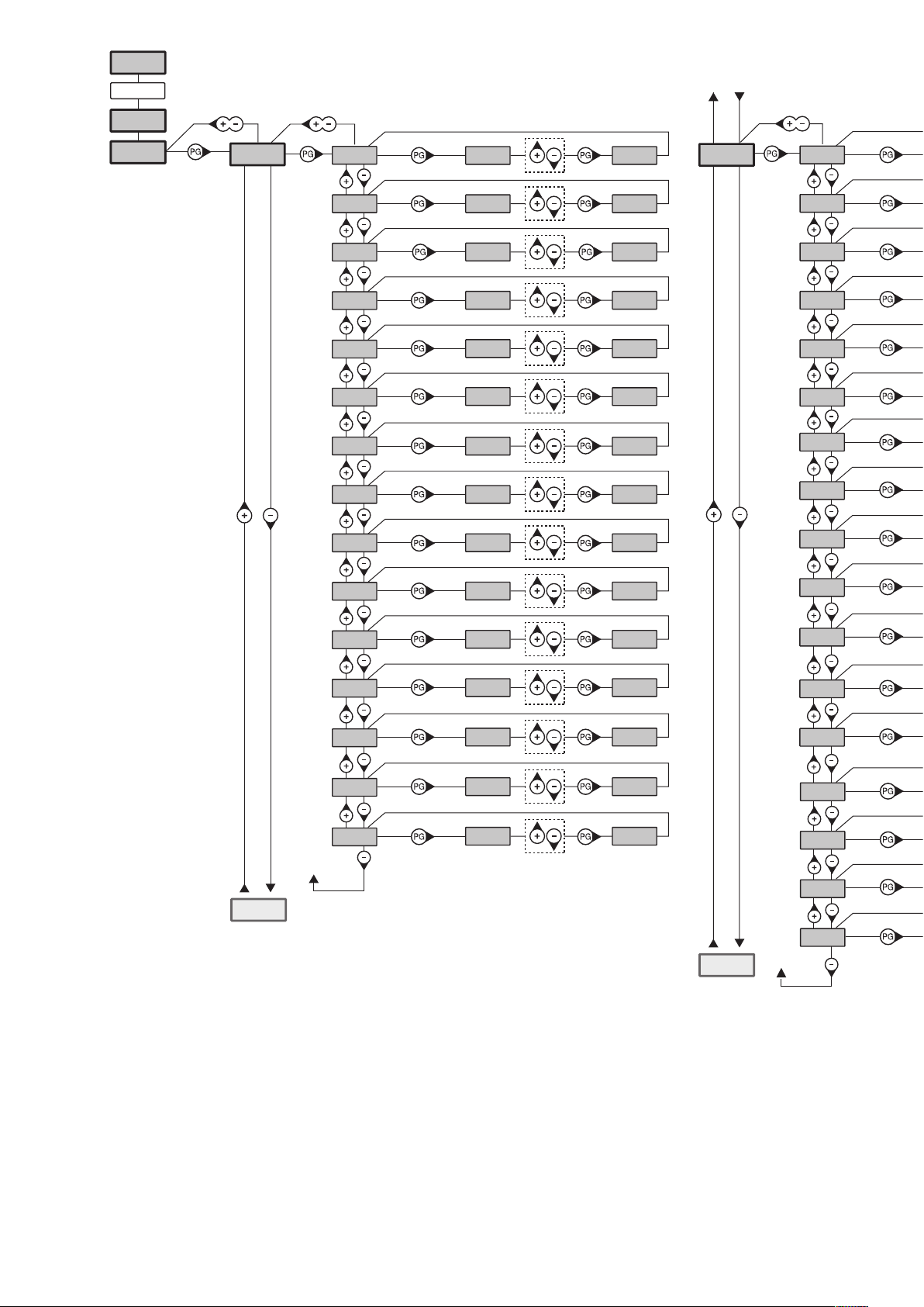
Schema menu di programmazione - Menu programming layout
Diagramm Programmiermenü - Menu de programmation
Menú de la carta de programación - Układ menu programowania
Diagnostic
8888
PAR
tca
tped
fsto
fstc
sldo
sldc
tsmo
tsmc
pmo
pmc
pso
40
50
99
99
50
50
20
20
20
20
20
PRG
PRG
PRG
PRG
PRG
PRG
PRG
PRG
PRG
PRG
PRG
LOG
tca
IBL
IBCA
SCL
PP
PRE
htr
opcl
ltca
phcl
opcl
LOG
TCA
psc
TLS
aux1
aux2
20
60
PRG
PRG
0
1
PRG
PRG
radi
TCA
tst1
tst2
bar
aopf
minv
rem
10
Page 11

on PRG
RADI
pp
PUSH OK
OFF PRG
OFF PRG
OFF PRG
OFF PRG
OFF PRG
OFF PRG
off PRG
off PRG
OFF PRG
off PRG
off PRG
2ch
n TX
clr
rtr
PUSH OK
0012
PUSH OK
rtr PRG OK
TCA
Nman
MACI
RES
AUTO OK
0012 3456
OFF PRG
res PRG
PUSH
2 Cycle
OPEN/CLOSE
off PRG
off PRG
off PRG
on PRG
off PRG
Legenda
Premere il tasto (-) / Press key (-) / Die Taste (-) drücken
Appuyez sur la touche (-) / Presionar la tecla (-) / Wcisnąć przycisk (-)
Premere il tasto (+) / Press key (+) / Die Taste (+) drücken
Appuyez sur la touche (+) / Presionar la tecla (+) / Wcisnąć przycisk (+)
Premere il tasto (PG) / Press key (PG) / Die Taste (PG) drücken
Appuyez sur la touche (PG) / Presionar la tecla (PG )/ Wcisnąć przycisk (PG)
CODE
BUS
0000 conf OK
ID
Loc
9000 9C5a
0
OFF
PRG
PRG
RE-ENTER
idpar
Premere simultaneamente (+) e (-) / Press simultaneously keys (+) and (-)
Gleichzeitig (+) und (-) drücken / Presser simultanément (+) et (-)
Presionar simultáneamente (+) y (-) / Naciskać jednocześnie (+) i (-)
Selezionare il valore desiderato con i pulsanti (+) e (-)
Increase/decrease the value with keys (+) and (-)
Mit den Tasten (+) und (-) kann man eingerichtete Werte ändern
Régler la valeur désirée avec les touches (+) et (-)
Establecer con las teclas (+) y (-) el valor deseado
Nastawia przyciskami (+) i (-) obraną wartoś
Selezionare il pulsante del trasmettitore da associare alla funzione
Press the transmitter key, which is to be assigned to function
Taste des Sendegeräts drücken, dem diese Funktion zugeteilt werden soll.
Appuyer sur la touche du transmetteur qu’e l’on désire affecter à cette fonction.
Presionar la tecla del transmisor que se desea asignar a esta función.
Wcisnąć przycisk nadajnika, który zamierza się skojarzyć z tą funkcją.
CODE
Display OFF
11
Page 12
SOMMARIO
1) DESCRIZIONE E DESTINAZIONE D'USO .....................................................13
2) DATI TECNICI.............................................................................................13
3) VERIFICHE PRELIMINARI ........................................................................... 13
4) INSTALLAZIONE .......................................................................................14
4.1) DIMENSIONI .................................................................................... 14
4.2) POSA CON PIASTRA DI FONDAZIONE RIALZATA BULL.PI OPZIONALE 14
4.3) POSA CON REGOLAZIONE IN ALTEZZA SU FONDO IN CEMENTO GIÀ
ESISTENTE ............................................................................................. 14
4.4) POSA CON REGOLAZIONE IN ALTEZZA SU FONDO IN CEMENTO DA
REALIZZARE ........................................................................................... 14
4.5) FISSAGGIO CREMAGLIERA ............................................................... 14
5) MANOVRA MANUALE ................................................................................14
6) POSIZIONAMENTO STAFFE FINECORSA .....................................................14
7) INSTALLAZIONE DEI MAGNETI (BULL 1224 TURBO.S O ACCESSORIO MLS) 14
8) CENTRALE DI COMANDO CP.B24 TURBO ...................................................14
8.1) COLLEGAMENTI ELETTRICI .............................................................. 14
8.2) PROGRAMMAZIONE ......................................................................... 15
8.2.1 )PER ACCEDERE ALLA PROGRAMMAZIONE: ............................. 15
8.2.2) NOTE SULLA PROGRAMMAZIONE ........................................... 15
8.3) COLLAUDO ...................................................................................... 15
8.4) PARAMETRI, LOGICHE E FUNZIONI SPECIALI .................................... 16
8.4.1) PARAMETRI (PAR) .................................................................. 16
8.4.2) LOGICHE (LOG) ............................................................ 16
8.4.4) NUMERO MANOVRE (NMAN) ............................................18
8.4.5) CICLI MANUTENZIONE (MACI) .........................................18
8.4.6) RESET (RES) ...............................................................18
8.4.7) AUTOSET (AUTO) ................................................................... 18
8.4.8) PASSWORD DI ACCESSO (CODE)............................................ 18
8.4.9) SINCRONISMO (BUS) ............................................................. 19
8.5) SINCRONIZZAZIONE DI DUE SCORREVOLI CONTRAPPOSTI ............... 19
8.6) APPRENDIMENTO REMOTO TRASMETTITORI.................................... 19
8.7) FUSIBILI .......................................................................................... 19
8.8) BATTERIA DI EMERGENZA ...............................................................19
8.9) DIAGNOSTICA .................................................................................. 19
8.10) MESSAGGI DI ERRORE ................................................................... 19
9) MANUTENZIONE........................................................................................20
ITA
INFORMAZIONI GENERALI
E’ vietato l’utilizzo del prodotto per scopi o con modalità non previste nel presente manuale. Usi non corretti possono essere causa di danni
al prodotto e mettere in pericolo persone e cose. Si declina ogni responsabilità dall’inosservanza della buona tecnica nella costruzione dei
cancelli, nonché dalle deformazioni che potrebbero verificarsi durante l’uso. Conservare questo manuale per futuri utilizzi.
INFORMAZIONI PER L'INSTALLATORE
Questo manuale è destinato esclusivamente a personale qualificato per l’installazione e la manutenzione di aperture automatiche.
L’installazione deve essere effettuaua da personale qualificato (installatore professionale, secondo EN12635), nell’osservanza della Buona
Tecnica e delle norme vigenti. Verificare che la struttura del cancello sia adatta ad essere automatizzata.
L’installatore deve fornire tutte le informazioni relative al funzionamento automatico, manuale e di emergenza dell’automazione, e consegnare
all’utilizzatore dell’impianto le istruzioni d’uso.
AVVERTENZE GENERALI
I materiali dell’imballaggio non devono essere lasciati alla portata dei bambini in quanto fonte di potenziale pericolo. Non disperdere
nell’ambiente i materiali di imballo, ma separare le varie tipologie (es. cartone, polistirolo) e smaltirle secondo le normative locali.
Non permettere ai bambini di giocare con i dispositivi di comando del prodotto. Tenere i telecomandi lontano dai bambini.
Questo prodotto non è destinato a essere utilizzato da persone (bambini inclusi) con capacità fisiche, sensoriali o mentali ridotte, o con mancanza di conoscenze adeguate, a meno che non siano sotto supervisione o abbiano ricevuto istruzioni d’uso da persone responsabili della
loro sicurezza. Applicare tutti i dispositivi di sicurezza (fotocellule, coste sensibili, ecc.) necessari a proteggere l’area da pericoli di impatto,
schiacciamento, convogliamento, cesoiamento. Tenere in considerazione le normative e le direttive in vigore, i criteri della Buona Tecnica,
l’utilizzo, l’ambiente di installazione, la logica di funzionamento del sistema e le forze sviluppate dall’automazione.
L’installazione deve essere fatta utilizzando dispositivi di sicurezza e di comandi conformi alla EN12978 e EN12453.
Raccomandiamo di utilizzare accessori e parti di ricambio originali, utilizzando ricambi non originali il prodotto non sarà più coperto da garanzia.
Tutte le parti meccaniche ed elettroniche che compongono l'automazione soddisfano i requisiti e le norme in vigore e presentano marcatura CE.
SICUREZZA ELETTRICA
Prevedere sulla rete di alimentazione un interruttore/sezionatore onnipolare con distanza d’apertura dei contatti uguale o superiore a 3 mm.
Verificare che a monte dell’impianto elettrico vi sia un interruttore differenziale e una protezione di sovracorrente adeguati.
Alcune tipologie di installazione richiedono il collegamento dell’anta ad un impianto di messa a terra rispondente alle vigenti norme di sicurezza.
Durante gli interventi di installazione, manutenzione e riparazione, togliere l’alimentazione prima di accedere alle parti elettriche.
Scollegare anche eventuali batterie tampone se presenti. L’installazione elettrica e la logica di funzionamento devono essere in accordo con
le normative vigenti. I conduttori alimentati con tensioni diverse, devono essere fisicamente separati, oppure devono essere adeguatamente
isolati con isolamento supplementare di almeno 1 mm. I conduttori devono essere vincolati da un fissaggio supplementare in prossimità dei
morsetti. Ricontrollare tutti i collegamenti fatti prima di dare tensione. Gli ingressi N.C. non utilizzati devono essere ponticellati.
SMALTIMENTO
Come indicato dal simbolo a lato, è vietato gettare questo prodotto nei rifiuti domestici in quanto alcune parti che lo compongono potrebbero
risultare nocive per l’ambiente e la salute umana, se smaltite scorrettamente. L’apparecchiatura, pertanto, dovrà essere consegnata in adeguati
centri di raccolta differenziata, oppure riconsegnata al rivenditore al momento dell’acquisto di una nuova apparecchiatura equivalente. Lo
smaltimento abusivo del prodotto da parte dell’utente comporta l’applicazione delle sanzioni amministrative previste dalla normativa vigente.
Le descrizioni e le illustrazioni presenti in questo manuale non sono impegnative. Lasciando inalterate le caratteristiche essenziali del prodotto il fabbricante si riserva il diritto di apportare qualsiasi modifica di carattere tecnico, costruttivo o commerciale senza impegnarsi ad aggiornare la presente
pubblicazione.
12
AVVERTENZE
Page 13

PROGRAMMAZIONE RAPIDA
NOTA: Condizioni per programmazione rapida:
- Memoria del trasmettitore vuota
- Autoset mai eseguito.
- Valido solo con trasmettitori ARC (Advanced Rolling Code)
Nel caso si commetta qualche errore durante la fase di programmazione rapida è possibile togliere l'alimentazione di rete e riavviare
la procedura iniziale.
Fasi di Programmazione Rapida
1 - Sbloccare manualmente il cancello, portarlo in posizione di chiuso con relativo finecorsa attivato, ribloccare il cancello.
2 - Fornire tensione di rete.
3 - Il lampeggiante si accende (verificare che sia collegato).
4 - Si entra automaticamente nella fase di memorizzazione trasmettitori e la centrale si pone in attesa di un trasmettitore.
Per saltare la fase di programmazione rapida e procedere con la programmazione manuale premere + e - (ESC) contemporaneamente.
5 - Sul display appare la scritta lampeggiante TX00.
6 - Premere il tasto nascosto del trasmettitore da memorizzare.
7 - Sul display compare PUSH
8 - Premere il tasto desiderato da associare al ricevitore
9 - Sul display compare TX01 (nel caso del secondo trasmettitore TX02).
10 - Ripetere le operazioni ai punti 6 e 7 per i trasmettitori successivi da memorizzare fino ad un massimo di 99 verificando l'in
cremento sul display (esempio TX15).
11 - Per passare alla fase successiva di AUTOSET* premere il tasto di un trasmettitore già memorizzato fino alla visualizzazione
della scritta AUTO.
12 - Sul display compare la scritta AUTO e il cancello esegue automaticamente 3 manovre calcolando i parametri ottimali di funziona-
mento. Se l'operazione di autoset è andata a buon fine il cancello si ferma in posizione di aperto e sul display compare la scritta OK.
Il tempo massimo per programmare il primo trasmettitore è di 60 secondi.
Se necessario procedere con la configurazione manuale PARAMETRI e LOGICHE in base alla tipologia di installazione.
Questa funzione è INDISPENSABILE per impostare i valori ottimali di funzionamento dell’automazione.
*
.
IT
Trasmettitori ARC
IMPORTANTE, LEGGERE CON ATTENZIONE:
Il ricevitore radio presente in questo prodotto è compatibile esclusivamente con i trasmettitori ARC (Advanced Rolling Code) i quali, grazie alla codifica
a 128 bit, garantiscono una superiore sicurezza anticopiatura.
La memorizzazione dei nuovi trasmettitori ARC è del tutto analoga a quella dei normali trasmettitori Rolling Code con codifica HCS.
1) DESCRIZIONE E DESTINAZIONE D'USO
Motoriduttore 24Vdc per cancelli scorrevoli ad uso condominiale e industriale fino a 1500 Kg per uso intensivo dotato di centrale incorporata CP.B24 TURBO
Vi ricordiamo che registrandovi sul sito www.beninca.com avrete accesso a tutta la documentazione tecnica aggiornata per tutti i prodotti e gli accessori
ed alla guida per compilazione del fascicolo tecnico e dei documenti previsti dall'allegato V della Direttiva Macchine, obbligatorio ai sensi delle normative
vigenti in materia.
2) DATI TECNICI
BULL 1224 TURBO
Alimentazione di rete 115 o 230 Vac 50/60 Hz
Assorbimento 3A (230V) - 5A (115V)
Coppia 20 Nm
Intermittenza di lavoro uso intensivo
Grado di protezione IP44
Temp. funzionamento -20°C / +50°C
Peso max. cancello 1200 kg
Modulo cremagliera M4/M6 accessorio - RI.P6
Velocità apertura 25 m/min
Rumorosità <70 dB
Lubrificazione GRASSO
N° TX memorizzabili 2048
Centrale di comando CP.B24 TURBO
Peso - kg
13
Page 14

3) VERIFICHE PRELIMINARI
Prima di procedere con l'installazione verificare quanto segue:
- La struttura (cancello, colonna, rotaia di guida) dev'essere solida e stabile.
- La rotaia di guida e relative ruote devono essere opportunamente dimensionate e manutenzionate per evitare eccessivi attriti durante lo scorrimento
del cancello.
- Se disponibile verificare il contenuto della dichiarazione CE di conformità del cancello ed eseguire analisi dei rischi secondo direttiva macchine.
- Verificare che la corsa del cancello venga limitata in apertura e chiusura da fermi meccanici di adeguata robustezza.
4) INSTALLAZIONE
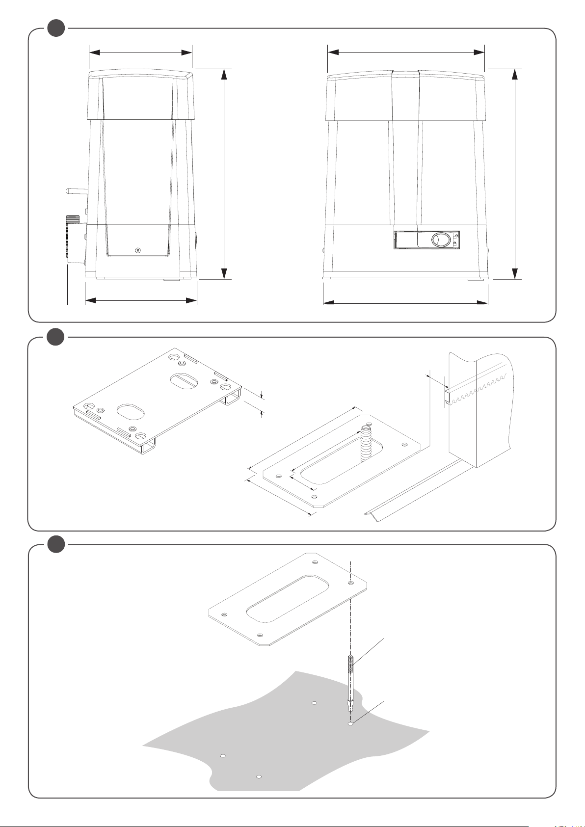
4.1) DIMENSIONI
In fig. 2 sono rappresentate le dimensioni della piastra di fondazione.
IMPORTANTE: è indispensabile rispettare la distanza dalla cremagliera (40 mm) per poter posizionare e rimuovere l'attuatore una volta fissata la cre-
magliera all'anta.
Le tipologie di fissaggio della piastra di fondazione sono principalmente le seguenti:
4.2) POSA CON PIASTRA DI FONDAZIONE RIALZATA BULL.PI OPZIONALE
E' disponibile su richiesta l'accessorio BULL.PI che consente il fissaggio rapido su pavimentazione in cemento esistente.
Consultare le istruzioni fornite con l'accessorio per ulteriori informazioni.
4.3) POSA CON REGOLAZIONE IN ALTEZZA SU FONDO IN CEMENTO GIÀ ESISTENTE
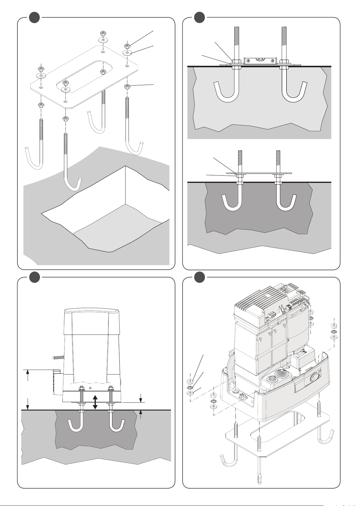
Utilizzando la piastra come dima di foratura, eseguire 4 fori, dove inserire dei tasselli per barre filettate in acciaio da Ø10mm.
Avvitare 4 barre filettate "S" da M10/120mm e ancorare i tasselli "T" avvitando a terra i dadi "B" con relativa rosetta.
Con riferimento alla Fig. 3 posizionare la piastra di fondazione con i dadi di regolazione "A". Posizionare il motore come indicato in Fig.6 e dopo aver
effettuato le opportune regolazioni, bloccarlo come indicato in Fig.7.
4.4) POSA CON REGOLAZIONE IN ALTEZZA SU FONDO IN CEMENTO DA REALIZZARE
Facendo riferimento alla fig.4, fissare i tirafondi sulla piastra di fondazione e predisporre uno scavo di dimensioni adeguate.
Annegare i tirafondi nel cemento, prestando attenzione al livello della piastra.
Attendere il consolidamento del getto di calcestruzzo, quindi rimuovere i dadi "D" e le rondelle "R" fascia larga 11x30 e portarli sotto la piastra per consentire le regolazioni in altezza dell'attuatore (Fig.5).
Effettuare le regolazioni evidenziate in Fig. 6 e bloccare il motore come indicato in Fig.7.
ATTENZIONE: indipendentemente dalla modalità di fissaggio utilizzata, è necessario verificare accuratamente la stabilità dell'attuatore e l'idoneità dei materiali utilizzati.
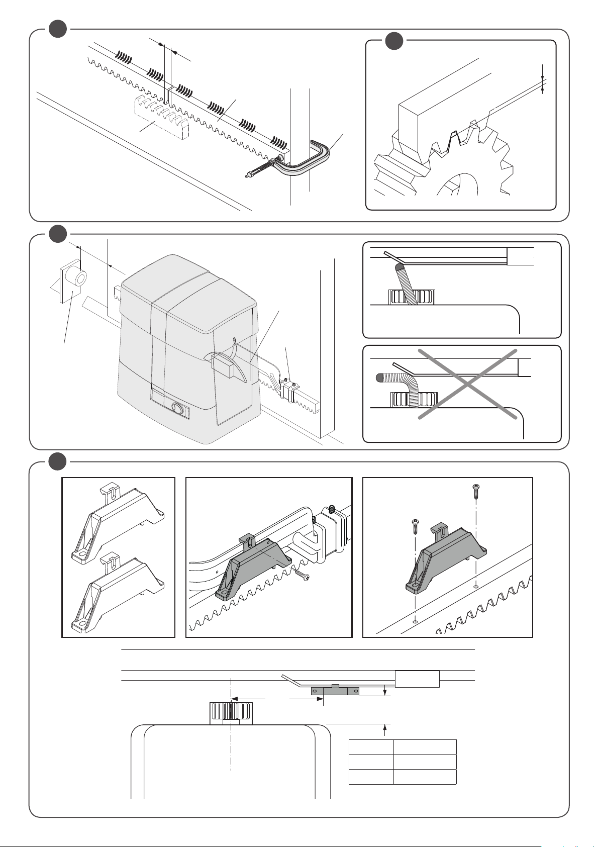
4.5) FISSAGGIO CREMAGLIERA
Cremagliera in Acciaio Zincato 123x30mm.
Posizionare i distanziali D saldandoli o avvitandoli sul cancello ad una altezza di 130/150 mm dalla mezzeria dell’asola di fissaggio alla base sulla quale
andrà fissata la piastra di fondazione.
Rispettare il passo di dentatura anche tra uno spezzone di cremagliera e l’altro; a tale scopo può essere utile accoppiare un’altro spezzone di cremagliera
(vedi Fig.8).
Fissare infine la cremagliera con le viti V, avendo cura, una volta installato l’attuatore, che rimanga circa 1mm di gioco tra cremagliera e ruota di trascinamento (vedi Fig.9); a tale scopo usufruire delle asole sulla cremagliera.
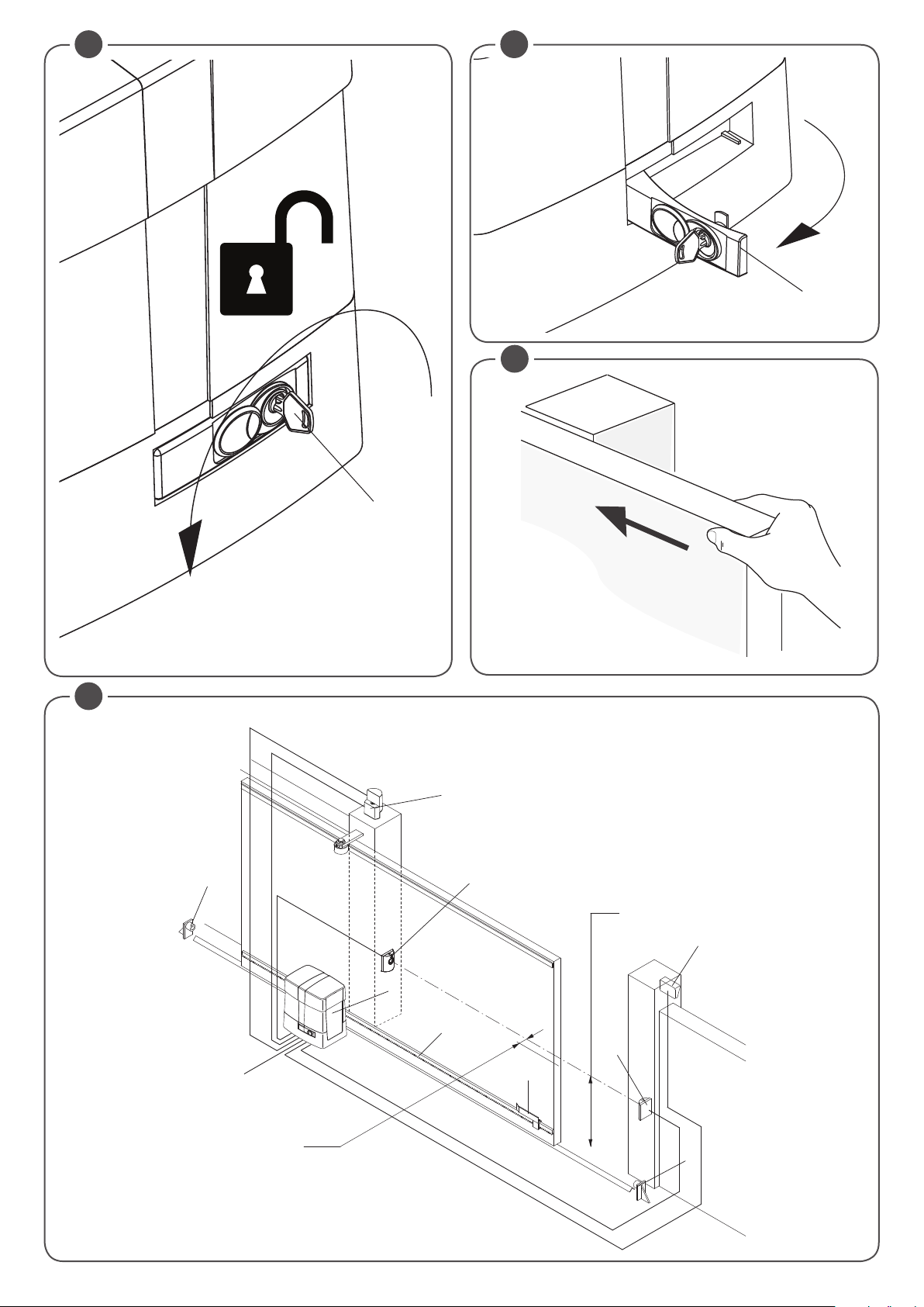
5) MANOVRA MANUALE (FIG. 12-13-14)
In caso di mancanza dell’energia elettrica o di guasto, per azionare manualmente l'anta procedere come segue :
- Inserita la chiave personalizzata C, farla ruotare in senso antiorario e tirare la leva L. (lucchetto aperto)
- Il motoriduttore è così sbloccato ed è possibile movimentare manualmente l'anta.
- Per ristabilire il normale funzionamento richiudere la leva L ed azionare il cancello manualmente fino ad ingranamento avvenuto.
6) POSIZIONAMENTO STAFFE FINECORSA
Portare manualmente il cancello in apertura lasciando una luce da 1 a 3cm a seconda del peso del cancello tra il portone stesso e l’arresto meccanico A;
fissare quindi la staffa del finecorsa S mediante i grani G in modo che il micro finecorsa sia premuto. Ripetere poi l’operazione con il portone in chiusura.
7) INSTALLAZIONE DEI MAGNETI (BULL 1224 TURBO.S O ACCESSORIO MLS) FIG.11
I magneti sono inseriti all’interno di speciali supporti (fig.11-”A”) i quali, posizionati sulle staffe finecorsa o sulla cremagliera, avvicinandosi ai sensori ne
provocano la commutazione.
7.1) APPLICAZIONE SU STAFFE FINECORSA
I supporti dispongono di alette di aggancio che consentono il fissaggio alle staffe finecorsa normalmente fornite con l’automazione come indicato in fig.11-B.
Questo tipo di fissaggio consente una veloce regolazione della posizione dei magneti. Dopo aver stabilito la distanza corretta fissare con una vite la
posizione del supporto, in modo da impedirne lo spostamento sulla staffa.
7.2) APPLICAZIONE SU CREMAGLIERA
E’ possibile in alternativa fissare i supporti direttamente sulla cremagliera, utilizzando le forature evidenziate in fig.11-C. Questa modalità non consente
regolazioni successive, pertanto è consigliabile effettuare delle prove con i supporti fissati provvisoriamente, prima del fissaggio definitivo.
IMPORTANTE: La corretta distanza del magnete rispetto al sensore dipende dalle caratteristiche dell’installazione e non può essere prestabilita ma
deve essere rilevata attraverso alcune prove.
Solo a titolo indicativo vengono riportate nella tabella di Fig. 11 alcune distanze di intervento del sensore (quota X) riferite a distanze K di 3 e 35 mm.
In ogni caso la distanza K non deve superare il valore di 35 mm poiché una distanza maggiore non consente la commutazione del sensore magnetico.
14
Page 15

8) CENTRALE DI COMANDO CP.B24 TURBO
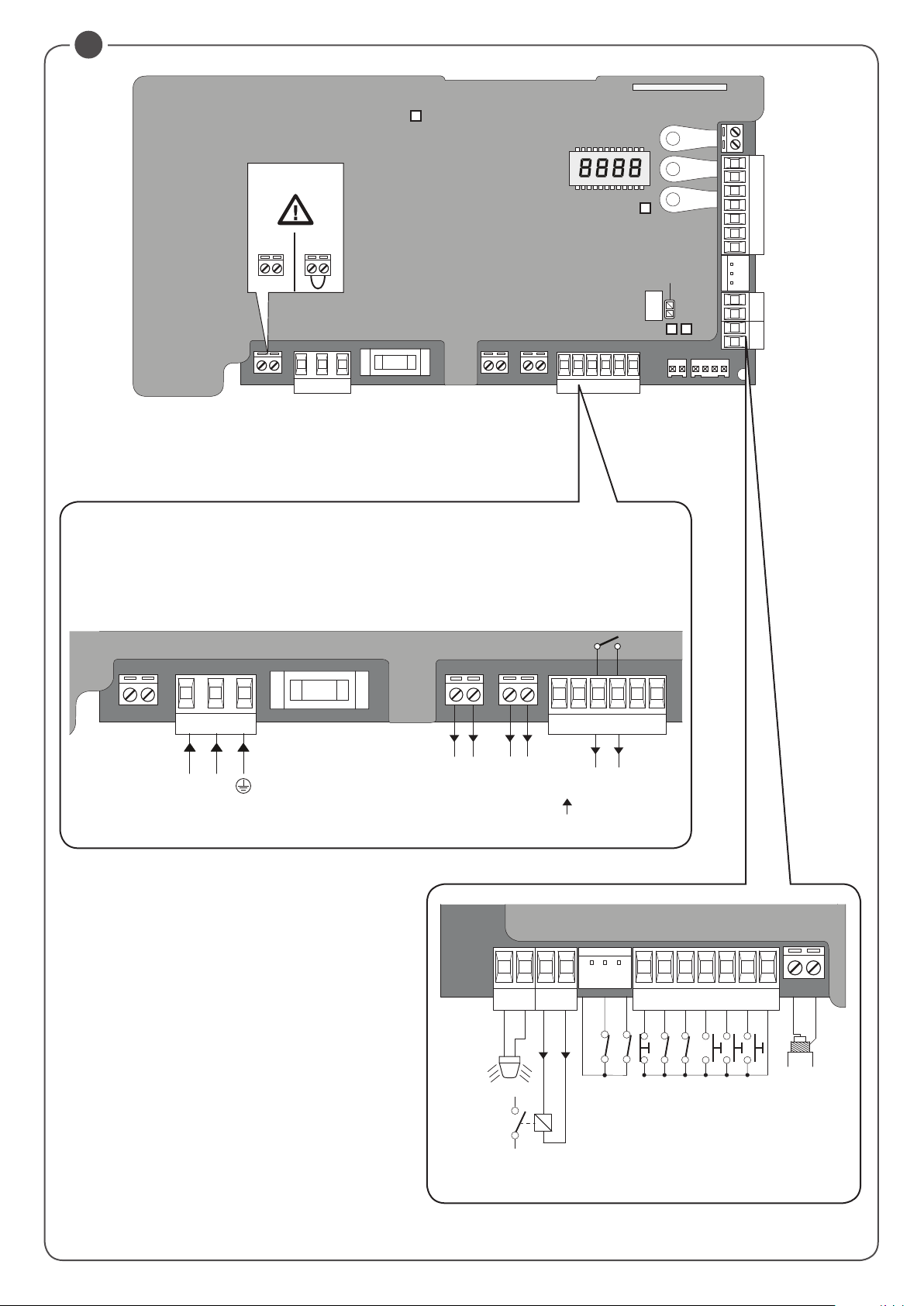
8.1) COLLEGAMENTI ELETTRICI
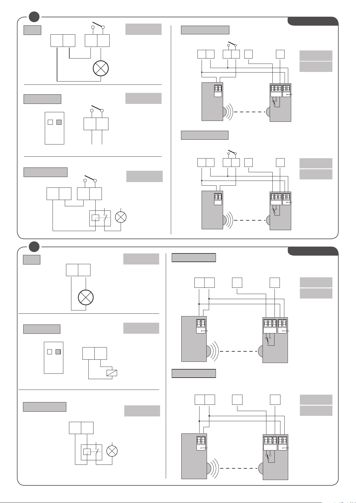
Nella seguente tabella sono descritti i collegamenti elettrici rappresentati in Fig. 17:
M2 SEL. 115V
L-N-GND Alimentazione di rete Ingresso alimentazione di rete selezionabile tramite ponticello M2.
+ BATT - Batterie Ingresso per il collegamento delle batterie tampone (accessorio) 2x12V 2,1Ah
M11 Motore Collegamento motore 24Vdc
+ 24 - 24 Vdc Uscita alimentazione accessori 24Vdc 0,8 A max (rispettare polarità accessori).
AUX1 Uscita ausiliaria AUX 1 Uscita con contatto N.O. configurabile dalla logica di funzionamento AUX1
BAR J3 Costa sensibile
RELEASE SW. Sensore Magnetico
S.I.S.
BLINK Lampeggiante Uscita 24Vdc 15W max. per collegamento al lampeggiante.
AUX2 Uscita ausiliaria AUX 2 Uscita 24 Vdc configurabile dalla logica di funzionamento AUX2 (0,5A max)
COM Comune Ingressi Comune per tutti gli ingressi di comando.
SWO Finecorsa apre Ingresso finecorsa APRE (contatto N.C.).
SWC Finecorsa chiude Ingresso finecorsa CHIUDE (contatto N.C.).
STOP STOP Ingresso pulsante STOP (contatto N.C.).
PHO
PHC Fotocellula chiusura
OPEN Apre Ingresso per comando di apertura configurabile come ingresso pedonale (Contatto N.O.)
CLOSE Chiude Ingresso per comando di chiusura (Contatto N.O.)
PP Passo-Passo Ingresso pulsante passo-passo (contatto N.O.)
COM Comune Ingressi Comune per tutti gli ingressi di comando.
ANT-SHIELD Antenna
Selezione Alimentazione
di rete
Scheda sincronismo
opzionale
Fotocellula apertura/
chiusura
230Vac 50/60Hz (da 207Vac a 253Vac) ponticello M2 APERTO
115Vac 50/60Hz (da 102Vac a 125 Vac) ponticello M2 CHIUSO
Ingresso contatto costa sensibile
Costa resistiva: Jumper “DAS” chiuso
Costa meccanica: Jumper “DAS” aperto
L’intervento della costa arresta il movimento dell’anta e inverte per circa 3s.
Se non si utilizza la costa: Jumper “DAS” aperto, ponticello tra i morsetti BAR.
Ingresso per microinterrutore di sicurezza collegato alla leva di sblocco. Arresta il moto del motore SE
LEVA SBLOCCO APERTA. Tutti i segmenti LED accesi.
Ingresso per scheda opzionale SIS per il sincronismo di due automazioni contrapposte.
Vedi paragrafo sincronizzazione di due automazioni.
Ingresso (contatto N.C.) per dispositivi di sicurezza (ad es. fotocellule).
In fase di chiusura: l’apertura del contatto provoca l’arresto del motore quando la fotocellula viene
liberata, il motore inverte la direzione di marcia (apre).
In fase di apertura: l’apertura del contatto provoca l’arresto del motore, quando la fotocellula viene
liberata, il motore riparte in apertura.
Ingresso (contatto N.C.) per dispositivi di sicurezza (ad es. fotocellule).
In fase di chiusura: Comportamento configurabile dalla logica PHCL.
In fase di apertura: Comportamento configurabile dalla logica PHCL.
Collegamento antenna scheda radioricevitore integrato (ANT-segnale/SHIELD-schermo).
IT
8.2) PROGRAMMAZIONE
La programmazione delle varie funzionalità della centrale viene effettuata utilizzando il display LCD presente a bordo della centrale ed impostando i valori
desiderati nei menu di programmazione descritti di seguito.
Il menu parametri consente di impostare un valore numerico ad una funzione, in modo analogo ad un trimmer di regolazione.
Il menu logiche consente di attivare o disattivare una funzione, in modo analogo al settaggio di un dip-switch.
8.2.1) PER ACCEDERE ALLA PROGRAMMAZIONE MANUALE:
1 - Premere il pulsante <PG>, il display si porta nel primo menu Installazione “PAR”.
2 - Scegliere con il pulsante <+> o <-> il menu che si intende selezionare.
3 - Premere il pulsante <PG>, il display mostra la prima funzione disponibile nel menu.
4 - Scegliere con il pulsante <+> o <-> la funzione che si intende modificare.
5 - Premere il pulsante <PG>, il display mostra il valore attualmente impostato per la funzione selezionata.
6 - Selezionare con il pulsante <+> o <-> il valore che si intende assegnare alla funzione.
7 - Premere il pulsante <PG>, il display mostra il segnale “PRG” che indica l’avvenuta programmazione.
8.2.2) NOTE SULLA PROGRAMMAZIONE
La pressione simultanea di <+> e <-> effettuata all’interno di un menu funzione consente di tornare al menu superiore senza apportare modifiche.
Mantenere la pressione sul tasto <+> o sul tasto <-> per accelerare l’incremento/decremento dei valori.
Dopo un’attesa di 120s la centrale esce dalla modalità programmazione e spegne il display.
La pressione del pulsante <-> a display spento equivale ad un comando passo-passo.
All’accensione della scheda viene visualizzata per circa 5s la versione software.
Le logiche ed i parametri preconfigurati di fabbrica tengono conto di una installazione tipica.
8.3) COLLAUDO
- Verificare il corretto funzionamento dei dispositivi di sicurezza.
- Verificare le forze operative nei punti previsti da EN 12445 con l'apposito strumento.
- Se i valori della forza risultano superiori, installare un dispositivo di protezione conforme alla norma EN12978 (ad esempio bordo sensibile) e ripetere le misure.
- Verificare il corretto settaggio della logica di funzionamento e che lo sblocco manuale funzioni correttamente.
15
Page 16

8.4) PARAMETRI, LOGICHE E FUNZIONI SPECIALI
Nelle tabelle di seguito vengono descritte le singole funzioni disponibili nella centrale.
8.4.1) PARAMETRI (PAR)
MENU FUNZIONE
TCA
Tped
fsto
fstc
sldo
sldc
tsmo
tsmc
PMO
PMC
PSO
Tempo di chiusura automatica. Attivo solo con logica “TCA”=ON.
Al termine del tempo impostato la centrale comanda una manovra di chiusura.
Regola lo spazio percorso dall’anta durante l’apertura parziale (pedonale) 10-99-(50)
Regola la velocità di apertura. 50-99-(99)
Regola la velocità di chiusura. 50-99-(99)
Regola la velocità dello scorrevole durante la fase di rallentamento in apertura*. 10-50-(25)
Regola la velocità dello scorrevole durante la fase di rallentamento in chiusura*. 10-50-(25)
Imposta il punto di inizio della fase di rallentamento in apertura. Il valore è espresso in percentuale
sull'intera corsa.
Imposta il punto di inizio della fase di rallentamento in chiusura. Il valore è espresso in percentuale sull'intera corsa.
Regola la coppia motore applicata allo scorrevole durante la fase di apertura.* 1-99-(20)
Regola la coppia motore applicata allo scorrevole durante la fase di chiusura.* 1-99-(20)
Regola la coppia motore applicata allo scorrevole durante la fase di rallentamento in apertura*. 1-99-(20)
MIN-MAX-(Default)
3-240-(40)
1-99-(20)
1-99-(20)
MEMO
PSC
tls
aux1
aux 2
* ATTENZIONE: UN’ERRATA IMPOSTAZIONE DI QUESTI PARAMETRI PUÒ RISULTARE PERICOLOSA.
RISPETTARE LE NORMATIVE VIGENTI!
Misurare che le forze di impatto rispettino quanto indicato dalla normativa en 12445, intervenendo se necessario sui parametri di funzionamento e
ripetendo le misure.
Dopo aver modificato manualmente i parametri SLDO, SLDC, PMO, PMC, PSO, PSC la centrale esegue una manovra completa di apprendimento
dei nuovi parametri..
Regola la coppia motore applicata allo scorrevole durante la fase di rallentamento in chiusura*. 1-99-(20)
Tempo di attivazione del contatto luce di cortesia. Valore espresso in secondi. Ad ogni manovra
il contatto viene chiuso per il tempo impostato.
Vedi descrizione parametro AUX1.
Seleziona la modalità di funzionamento dell’uscita AUX1:
0: Spia cancello aperto. La spia è spenta a porta chiusa, lampeggia con porta in movimento, è
accesa con porta aperta.
1: Secondo canale radio. L’uscita è controllata dal canale radio della ricevente incorporata (vedi
menu RADIO).
2: Luce di servizio. Il contatto si chiude per il tempo impostato con il parametro TLS. Il conteggio
inizia con l’inizio della manovra.
3: Fototest. Utilizzato per alimentare i trasmettitori delle fotocellule in modalità TEST.
Vedi schema di collegamento Fig.23.
Stesse opzioni di funzionamento dell’uscita AUX1, ma riferite ai morsetti AUX2.
ATTENZIONE!: L'uscita AUX2 presenta una tensione di 24Vdc/0,5 A Max, è possibile alimentare
direttamente i dispositivi 24Vdc, come indicato in Fig.24.
1-240 (60)
0-3-(1)
0-3-(0)
8.4.2) LOGICHE (LOG)
MENU FUNZIONE
Abilita o disabilita la chiusura automatica
TCA
IbL
ibca
SCL
PP
On: chiusura automatica abilitata
Off: chiusura automatica disabilitata
Abilita o disabilita la funzione condominiale.
On: funzione condominiale abilitata. L’impulso P.P. o del trasmettitore non ha effetto durante
la fase di apertura.
Off: funzione condominiale disabilitata.
Abilita o disabilita la funzione condominiale durante il conteggio TCA.
On: funzione condominiale abilitata. L’impulso P.P. o del trasmettitore non ha effetto durante il
conteggio del TCA.
Off: funzione condominiale -disabilitata.
Abilita o disabilita la chiusura rapida
On: chiusura rapida abilitata. Con cancello aperto o in movimento l’intervento della fotocellula
provoca la chiusura automatica dopo 3 s.Attiva solo con TCA:ON
Off: chiusura rapida disabilitata.
Seleziona la modalità di funzionamento del ”Pulsante P.P.” e del trasmettitore.
On: Funzionamento: APRE > CHIUDE > APRE >
Off: Funzionamento: APRE > STOP > CHIUDE > STOP >
ON-OFF-(DEFAULT)
(ON)
(OFF)
(OFF)
(OFF)
(OFF)
MEMO
16
Page 17

PRE
htr
ltca
phcl
OPCL
TST1
tst2
bar
aopf
minv
rem
Abilita o disabilita il pre-lampeggio.
On: Pre-lampeggio abilitato. Il lampeggiante si attiva 3s prima della partenza del motore.
Off: Pre-lampeggio disabilitato.
Abilita o disabilita la funzione Uomo presente.
On: Funzionamento Uomo Presente.
La pressione dei pulsanti APRE/CHIUDE deve essere mantenuta durante tutta la manovra.
L’apertura dell’ingresso STOP arresta il motore. Tutti gli ingressi di sicurezza sono disattivati.
Off: Funzionamento automatico.
Selezione la modalità di funzionamento del lampeggiante durante il tempo TCA
On: Lampeggiante acceso durante TCA
Off: Lampeggiante spento durante TCA
Seleziona la modalità di funzionamento dell’ingresso PHC.
On: Ingresso PHC attivo sia in apertura sia in chiusura.
In apertura: l’apertura del contatto provoca l’arresto del motore, quando la fotocellula viene
liberata, il motore riparte in apertura.
In chiusura: l’apertura del contatto provoca l’arresto del motore, quando la fotocellula viene
liberata, il motore inverte il senso di marcia (apre).
Off: Ingresso PHC attivo solo in chiusura.
In chiusura: l’apertura del contatto provoca l’arresto del motore e l’inversioneistantanea del
senso di marcia (apre).
Abilita l’ingresso OPEN come ingresso Pedonale (Apertura parziale parametro TPED).
On: Ingresso OPEN abilitato come ingresso pedonale (PED).
Off: Nessuna modifica all'ingresso OPEN
Abilita o disabilita la verifica delle fotocellule sull’ingresso PHOTO, attivo sia in chiusura, sia in
apertura.
On: Verifica abilitata. Se la verifica ha esito negativo non viene comandata nessuna manovra.
Vedi Fig.23 - “PHOTO TEST”. (AUX1=3)
Off: Verifica delle fotocellule ad ogni manovra disabilitata. Questa impostazione rende obbligatoria
ogni 6 mesi la manutenzione delle fotocellule.
Abilita o disabilita la verifica delle fotocellule sull’ingresso PHC.
On: Verifica abilitata. Se la verifica ha esito negativo non viene comandata nessuna manovra.
Vedi Fig.24 - “PHOTO TEST”.(AUX1=3)
Off: Verifica delle fotocellule ad ogni manovra disabilitata. Questa impostazione rende obbligatoria
ogni 6 mesi la manutenzione delle fotocellule.
Modifica la modalità di funzionamento degli ingressi PHO e BAR nel caso siano installate le coste
sensibili nei bordi mobili di apertura e chiusura (vedi Fig.21) .
On: L’ingresso PHO assume la funzione analoga all’ingresso BAR ma inverte il moto per 3s solo
durante la fase di apertura. La costa collegata all’ingresso BAR è attiva solo durante la fase di
chiusura.
Off: L’intervento della costa sensibile collegata all’ingresso BAR arresta il movimento dell’anta
e inverte per circa 3s, sia in apertura che in chiusura.
L’ingresso PHO riprende il funzionamento di fotocellula attiva in apertura.
Attiva o disattiva la funzione di “Apertura forzata in assenza di rete” (attivabile solo con batterie
di emergenza collegate e funzionanti).
On: Funzione attiva. In caso di mancanza di alimentazione di rete, prima che la batteria di emergenza si scarichi completamente, la centrale forza una manovra di apertura.
Lo scorrevole rimane aperto fino al ripristino dell'alimentazione di rete.
Off: Funzione non attiva.
Seleziona il verso di apertura del motore:
On: Motore installato a destra
Off: Motore installato a sinistra (fig.20)
Abilita o disabilita l’apprendimento remoto dei radiotrasmettitori, come indicato nel paragrafo
“Apprendimento remoto trasmettitori”.
On: Apprendimento remoto abilitato.
Off: Apprendimento remoto non abilitato.
(OFF)
IT
(OFF)
(OFF)
(OFF)
(OFF)
(OFF)
(OFF)
(OFF)
(OFF)
(OFF)
(ON)
8.4.3) RADIO (RADI)
MENU FUNZIONE
Selezionando questa funzione la ricevente si pone in attesa (Push) di un codice trasmettitore da assegnare alla funzione passo-passo.
PP
2Ch
ped
ntx
Premere il tasto del trasmettitore che si intende assegnare a questa funzione.
Se il codice è valido, viene memorizzato e viene visualizzato il messaggio OK
Se il codice non è valido, viene visualizzato il messaggio Err.
Selezionando questa funzione la ricevente si pone in attesa (Push) di un codice trasmettitore da assegnare al secondo canale radio.
Premere il tasto del trasmettitore che si intende assegnare a questa funzione.
Se il codice è valido, viene memorizzato e viene visualizzato il messaggio OK
Se il codice non è valido, viene visualizzato il messaggio Err.
Selezionando questa funzione la ricevente si pone in attesa (Push) di un codice trasmettitore da assegnare alla funzione PED. Premere
il tasto del trasmettitore che si intende assegnare a questa funzione.
Se il codice è valido, viene memorizzato e viene visualizzato il messaggio OK
Se il codice non è valido, viene visualizzato il messaggio Err.
Selezionando questa funzione il display LCD visualizza il numero di trasmettitori attualmente memorizzati nella ricevente.
17
Page 18

Selezionando questa funzione la ricevente si pone in attesa (Push) di un codice trasmettitore da cancellare dalla memoria.
CLR
RTR
Se il codice è valido, viene cancellato e viene visualizzato il messaggio OK
Se il codice non è valido o non è presente in memoria, viene visualizzato il messaggio Err
Cancella completamente la memoria della ricevente. Viene richiesta conferma dell’operazione.
Selezionando questa funzione la ricevente si pone in attesa (Push) di un una nuova pressione di PGM a conferma dell’operazione.
A fine cancellazione viene visualizzato il messaggio OK
8.4.4) NUMERO MANOVRE (NMAN)
Visualizza il numero di cicli completi (apre+chiude) effettuate dall’automazione. La prima pressione del pulsante <PG>, visualizza le prime 4 cifre, la
seconda pressione le ultime 4. Es. <PG> 0012 >>> <PG> 3456: effettuati 123.456 cicli.
8.4.5) CICLI MANUTENZIONE (MACI)
Questa funzione consente di attivare la segnalazione di richiesta manutenzione dopo un numero di manovre stabilito dall’installatore. Per attivare e
selezionare il numero di manovre, procedere come segue:
Premere il pulsante <PG>, il display visualizza OFF, che indica che la funzione è disabilitata (valore di default).
Con i pulsanti <+> e <-> selezionare uno dei valori numerici proposti (da OFF a 100). I valori vanno intesi come centinaia di cicli di manovre (ad es.:
il valore 50 sta ad indicare 5000 manovre). Premere il pulsante OK per attivare la funzione. Il display visualizza il messaggio PROG. La richiesta di
manutenzione viene segnalata all’utente mantenendo il lampeggiante acceso per altri 10s dopo la conclusione della manovra di apertura o chiusura.
8.4.6) RESET (RES)
RESET della centrale. ATTENZIONE!: Riporta la centrale ai valori di default.
La prima pressione del pulsante <PG> provoca il lampeggio della scritta RES, una ulteriore pressione del pulsante <PG> effettua il reset della centrale.
Nota: Non vengono cancellati i trasmettitori dalla ricevente ne la password di accesso e la configurazione del sincronismo.
Vengono riportati ai valori di default tutte le logiche e tutti i parametri, è pertanto necessario ripetere la procedura di autoset.
8.4.7) AUTOSET (AUTO)
Questa funzione permette di impostare i valori ottimali di funzionamento dell’automazione, e al termine della procedura, setta dei valori medi di COPPIA
(PMO/PMC e PSO/PSC).
Per effettuare l’autoset, procedere come segue:
a) Accertarsi che nell’area di manovra non siano presenti ostacoli di nessuna natura, se necessario, transennare l’area in modo da impedire l’accesso
a persone, animali, auto, ecc.
Durante la fase di autoset, la funzione di antischiacciamento non è attiva, mentre l'attivazione degli ingressi e sicurezze genera un errore
(vedi Paragrafo 8.10)
b) Selezionare la funzione AUTO e premere PG.
c) la centrale si pone in attesa di conferma di inizio procedura "AUTO" LAMPEGGIANTE
c) premere PG per dare inizio alla fase di autoset.
La centrale esegue una serie di manovre per l’apprendimento della corsa e per la configurazione dei parametri.
Nel caso l’operazione non abbia esito positivo viene visualizzato il messaggio ERR. Ripetere l’operazione dopo aver ricontrollato i cablaggi e l’eventuale
presenza di ostacoli.
8.4.8) PASSWORD DI ACCESSO (CODE)
Consente di inserire un codice di protezione di accesso alla programmazione della centrale.
E’ possibile inserire un codice alfanumerico di quattro caratteri utilizzando i numeri da 0 a 9 e le lettere A-B-C-D-E-F.
Il valore di default è 0000 (quattro zeri) e indica l’assenza di codice di protezione.
In qualsiasi momento è possibile annullare l’operazione di inserimento del codice, premendo contemporaneamente i tasti + e -. Una volta inserita la
password è possibile operare sulla centrale, entrando ed uscendo dalla programmazione per un tempo di circa 10 minuti, in modo da consentire le
operazioni di regolazione e test delle funzioni.
Sostituendo il codice 0000 con qualsiasi altro codice si abilita la protezione della centrale, impedendo l’accesso a tutti i menu. Se si desidera inserire
un codice di protezione, procedere come segue:
- selezionare il menu Code e premere OK.
- viene visualizzato il codice 0000, anche nel caso sia già stato inserito in precedenza un codice di protezione.
- con i tasti + e - si può variare il valore del carattere lampeggiante.
- con il tasto OK si conferma il carattere lampeggiante e si passa al successivo.
- dopo aver inserito i 4 caratteri compare un messaggio di conferma “CONF”.
- dopo alcuni secondi viene ri-visualizzato il codice 0000
- è necessario riconfermare il codice di protezione precedentemente inserito, in modo da evitare inserimenti involontari.
Se il codice corrisponde al precedente, viene visualizzato un messaggio di conferma “OK”
La centrale esce automaticamente dalla fase di programmazione, e per accedere nuovamente ai menu sarà necessario inserire il codice di protezione memorizzato.
IMPORTANTE: ANNOTARE il codice di protezione e CONSERVARLO IN LUOGO SICURO per future manutenzioni. Per rimuovere un codice da una
centrale protetta è necessario entrare in programmazione con la password e riportare il codice al valore di default 0000.
IN CASO DI SMARRIMENTO DEL CODICE È NECESSARIO RIVOLGERSI ALL’ASSISTENZA
TECNICA AUTORIZZATA, PER IL RESET TOTALE DELLA CENTRALE.
8.4.9) SINCRONISMO (BUS)
MENU FUNZIONE
id
loc
Imposta il numero id di sincronismo. E' possibile impostare un valore numerico da 0 a 16.
Se impostata con il valore 0 la centrale viene configurata come MASTER, tutti gli altri valori la configurano come SLAVE.
Consente ad una centrale configurata come SLAVE di accettare comandi locali.
Vedi paragrafo 8.5 "SINCRONIZZAZIONE DI DUE SCORREVOLI CONTRAPPOSTI"
18
Page 19
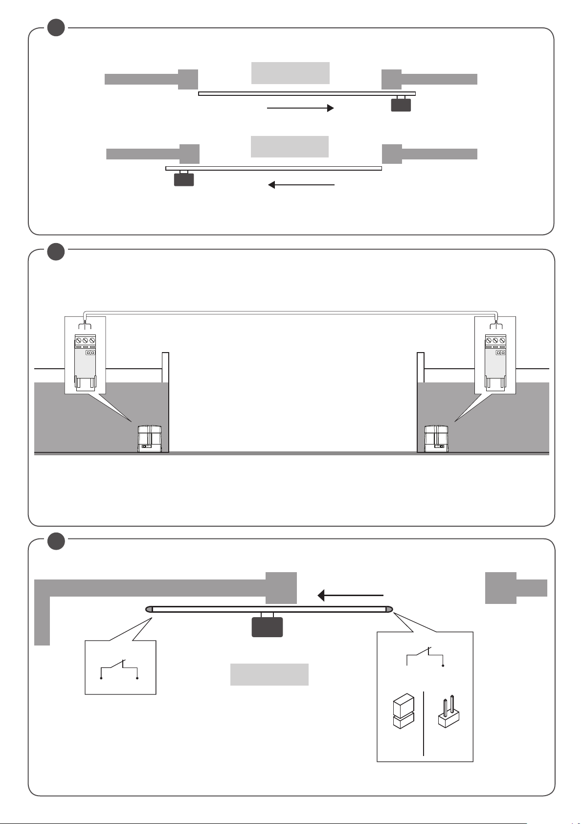
8.5) SINCRONIZZAZIONE DI DUE SCORREVOLI CONTRAPPOSTI
E' possibile gestire un sistema formato da due scorrevoli utilizzando su ogni scheda CP.B24 TURBO l'apposita scheda opzionale di sincronismo SIS, da
innestare nell'apposito connettore come indicato in Fig.21.
Ogni scheda deve essere interconnessa utilizzando 3 fili da 0,5mmq, come indicato in Fig.21.
Una delle due schede deve essere impostata come MASTER (ID=0), l'altra come SLAVE (ID=1)
Tutti i comandi (sia da radiotrasmettitori, sia da ingressi di comando e sicurezze) ricevuti dallo scorrevole MASTER verranno quindi trasmessi allo scorrevole SLAVE, che replicherà istantaneamente il comportamento dello scorrevole MASTER.
La logica LOC può essere settata in due modi:
ON: lo scorrevole SLAVE può accettare un comando locale e di conseguenza può effettuare una manovra di apertura e/o chiusura senza che ci sia un
effetto sullo scorrevole MASTER.
OFF: lo scorrevole SLAVE non accetta comandi locali, replicherà quindi sempre e comunque lo stato dello scorrevole MASTER.
Uno scorrevole SLAVE con LOC impostato in ON può ad esempio essere utile nel caso sia occasionalmente necessaria l'apertura parziale di un passaggio
che normalmente viene gestita da due scorrevoli contrapposti, dato che un pulsante Passo-Passo (o OPEN/CLOSE) collegato allo scorrevole SLAVE avrà
effetto solo su quest'ultima, mentre tutti i comandi alla MASTER saranno replicati dalla SLAVE.
I collegamenti dei dispositivi di sicurezza (fotocellule, bordi sensibili, ecc) possono essere collegati indifferentemente sulla scheda MASTER o SLAVE.
8.6) APPRENDIMENTO REMOTO TRASMETTITORI
Se si dispone di un trasmettitore già memorizzato nella ricevente è possibile effettuare l’apprendimento radio remoto (senza necessità di accedere alla centrale).
IMPORTANTE: La procedura deve essere eseguita con cancello in posizione di apertura. La logica REM deve essere ON.
Procedere come segue:
1 Premere il tasto nascosto del trasmettitore già memorizzato.
2 Premere, entro 5s, il tasto del trasmettitore già memorizzato corrispondente al canale da associare al nuovo trasmettitore. Il lampeggiante si accende.
3 Premere entro 10s il tasto nascosto del nuovo trasmettitore.
4 Premere, entro 5s, il tasto del nuovo trasmettitore da associare al canale scelto al punto 2. Il lampeggiante si spegne.
5 La ricevente memorizza il nuovo trasmettitore ed esce immediatamente dalla programmazione.
Nota: Funzione non utilizzabile con TO.GO 2/4 AK
8.7) FUSIBILI
F2 =T4A - Fusibile di protezione generale
IT
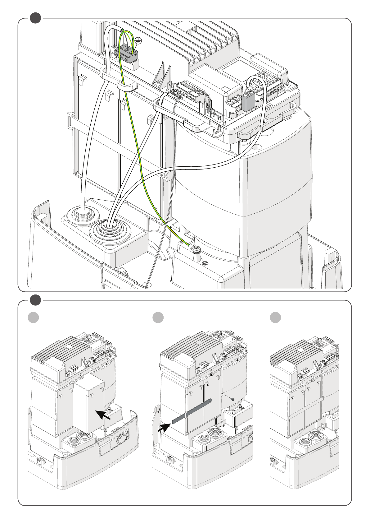
8.8) BATTERIA DI EMERGENZA
La centrale CP.B24 TURBO è dotata di caricabatterie integrato per la gestione in serie di due batterie 12V 2,1 Ah DA.BT2 (opzionali - fig. 19) che consentono il funzionamento dell'automazione anche nel caso di temporanea assenza dell'alimentazione di rete.
Durante il normale funzionamento di rete la scheda provvede alla ricarica delle batterie.
La corrente di carica massima è di 1A, la corrente di carica media è di 300mA. (rispettare la polarità).
Tempo di ricarica con batterie da 2,1Ah mod. DA.BT2: circa 3h.
Numero di cicli con batteria carica cu cancello da 4m/600kg.: circa 20.
8.9) DIAGNOSTICA
DL 1 : Presenza alimentazione di rete
SWO
P.P.
PHO
PHC BAR
SWC
OPEN
/PED
STOP
CLOSE
DL 2 : Centrale di comando CP.B24 TURBO alimentata correttamente - Programma funzionante/Centrale
programmata.
DL 3 : Segnalazione sovraccarico o cortocircuito su uscita 24V.
DL 4 : Segnalazione cortocircuito su Comune Comandi (COM).
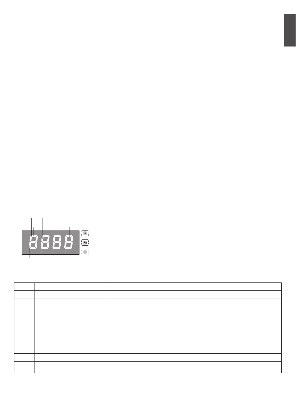
Ad ogni ingresso è associato un segmento del display che in caso di attivazione si accende, secondo
il seguente schema.
Gli ingressi N.C. sono rappresentati dai segmenti verticali.
Gli ingressi N.O. sono rappresentati dai segmenti orizzontali.
Nota: Con motore sbloccato, si accendono simultaneamente SWO/SWC/PHO/PHC/STOP/BAR
8.10) MESSAGGI DI ERRORE
Di seguito sono elencati alcuni messaggi che vengono visualizzati dal display in caso di anomalie di funzionamento:
Err1
Err2
Err4
Err5
Err7
Err8
AMP
THRM
OVLD
bar
Errore motore
Errore verifica fotocellule
errore ingresso COSTA durante autoset
Errore PHOT chiusura
errore ingresso STOP durante autoset
Errore ATTIVAZIONE INGRESSI (START/
OPEN/CLOSE) durante Autoset
Intervento sensore amperometrico Verificare presenza ostacoli o attriti.
Intervento sensore termico
Sovraccarico Superamento della potenza massima. Verificare motore o presenza attriti.
Intervento ingresso COSTA durante la
manovra
Verificare collegamenti motore, motore scollegato o non funzionante, problema su centrale di comando.
Surriscaldamento dovuto ad ostacoli permanenti. Sbloccare il cancello e verificare non ci siano
punti di attrito.
19
Page 20

9) MANUTENZIONE
La seguente tabella serve per registrare gli interventi di manutenzione, miglioramento o riparazione effettuati dal tecnico specializzato.
Data _ _ _ _ _ _ _ _ _ _ _ _ _ _ _ _ _ _ _ _ _ _ _ _ _ _ _ _ _ _ _ _ Firma Tecnico _ _ _ _ _ _ _ _ _ _ _ _ _ _ _ _ _ _ _ _ _ _ _ _ _ _ _
Descrizione intervento
_ _ _ _ _ _ _ _ _ _ _ _ _ _ _ _ _ _ _ _ _ _ _ _ _ _ _ _ _ _ _ _ _ _ _ _ _ _ _ _ _ _ _ _ _ _ _ _ _ _ _ _ _ _ _ _ _ _ _ _ _ _ _ _ _ _ _ _ _ _ _ _ _
_ _ _ _ _ _ _ _ _ _ _ _ _ _ _ _ _ _ _ _ _ _ _ _ _ _ _ _ _ _ _ _ _ _ _ _ _ _ _ _ _ _ _ _ _ _ _ _ _ _ _ _ _ _ _ _ _ _ _ _ _ _ _ _ _ _ _ _ _ _ _ _ _
Timbro
Data _ _ _ _ _ _ _ _ _ _ _ _ _ _ _ _ _ _ _ _ _ _ _ _ _ _ _ _ _ _ _ _ Firma Tecnico _ _ _ _ _ _ _ _ _ _ _ _ _ _ _ _ _ _ _ _ _ _ _ _ _ _ _
Descrizione intervento
_ _ _ _ _ _ _ _ _ _ _ _ _ _ _ _ _ _ _ _ _ _ _ _ _ _ _ _ _ _ _ _ _ _ _ _ _ _ _ _ _ _ _ _ _ _ _ _ _ _ _ _ _ _ _ _ _ _ _ _ _ _ _ _ _ _ _ _ _ _ _ _ _
_ _ _ _ _ _ _ _ _ _ _ _ _ _ _ _ _ _ _ _ _ _ _ _ _ _ _ _ _ _ _ _ _ _ _ _ _ _ _ _ _ _ _ _ _ _ _ _ _ _ _ _ _ _ _ _ _ _ _ _ _ _ _ _ _ _ _ _ _ _ _ _ _
Timbro
Timbro
Timbro
Timbro
Data _ _ _ _ _ _ _ _ _ _ _ _ _ _ _ _ _ _ _ _ _ _ _ _ _ _ _ _ _ _ _ _ Firma Tecnico _ _ _ _ _ _ _ _ _ _ _ _ _ _ _ _ _ _ _ _ _ _ _ _ _ _ _
Descrizione intervento
_ _ _ _ _ _ _ _ _ _ _ _ _ _ _ _ _ _ _ _ _ _ _ _ _ _ _ _ _ _ _ _ _ _ _ _ _ _ _ _ _ _ _ _ _ _ _ _ _ _ _ _ _ _ _ _ _ _ _ _ _ _ _ _ _ _ _ _ _ _ _ _ _
_ _ _ _ _ _ _ _ _ _ _ _ _ _ _ _ _ _ _ _ _ _ _ _ _ _ _ _ _ _ _ _ _ _ _ _ _ _ _ _ _ _ _ _ _ _ _ _ _ _ _ _ _ _ _ _ _ _ _ _ _ _ _ _ _ _ _ _ _ _ _ _ _
Timbro
Timbro
Timbro
Timbro
20
Page 21

INDEX
1) DESCRIPTION AND INTENDED USE ...........................................................22
2) SPECIFICATIONS .......................................................................................22
3) PRELIMINARY CHECKS .............................................................................22
4) INSTALLATION...........................................................................................23
4.1) OVERALL DIMENSIONS .................................................................... 23
4.2) INSTALLATION WITH OPTIONAL BULL.PI RAISED BEDPLATE ............. 23
4.3) INSTALLATION ON THE ALREADY EXISTING BASE IN CONCRETE ....... 23
4.4) INSTALLATION WITH ADJUSTMENT IN HEIGHT ON CONCRETE BASE 23
4.5) RACK FIXING ................................................................................... 23
5) MANUAL OPERATION ................................................................................23
6) HOW TO POSITION THE LIMIT SWITCH BRACKETS ..................................... 23
7) HOW TO INSTALL THE MAGNETS (BULL 1224 TURBO.S OR ACC. MLS) .......23
7.1) FITTING ONTO THE LIMIT SWITCH BRACKETS .................................. 23
7.2) FITTING ONTO THE RACK ................................................................ 23
ENG
GENERAL INFORMATIONS
The product shall not be used for purposes or in ways other than those for which the product is intended for and as described in this manual.
Incorrect uses can damage the product and cause injuries and damages.
The company shall not be deemed responsible for the non-compliance with a good manufacture technique of gates as well as for any deformation, which might occur during use. Keep this manual for further use.
INSTALLER GUIDE
This manual has been especially written to be use by qualified fitters.
Installation must be carried out by qualified personnel (professional installer, according to EN 12635), in compliance with Good Practice
and current code.
Make sure that the structure of the gate is suitable for automation.
The installer must supply all information on the automatic, manual and emergency operation of the automatic system and supply the end
user with instructions for use.
GENERAL WARNINGS
Packaging must be kept out of reach of children, as it can be hazardous.
For disposal, packaging must be divided the various types of waste (e.g. carton board, polystyrene) in compliance with regulations in force.
Do not allow children to play with the fixed control devices of the product.
Keep the remote controls out of reach of children.
This product is not to be used by persons (including children) with reduced physical, sensory or mental capacity, or who are unfamiliar with
such equipment, unless under the supervision of or following training by persons responsible for their safety.
Apply all safety devices (photocells, safety edges, etc.) required to keep the area free of impact, crushing, dragging and shearing hazard.
Bear in mind the standards and directives in force, Good Practice criteria, intended use, the installation environment, the operating logic of
the system and forces generated by the automated system.
Installation must be carried out using safety devices and controls that meet standards EN 12978 and EN 12453.
Only use original accessories and spare parts, use of non-original spare parts will cause the warranty planned to cover the products to
become null and void.
All the mechanical and electrical parts composing automation must meet the requirements of the standards in force and outlined by CE marking.
ELECTRICAL SAFETY
An omnipolar switch/section switch with remote contact opening equal to, or higher than 3mm must be provided on the power supply mains.
Make sure that before wiring an adequate differential switch and an overcurrent protection is provided.
Pursuant to safety regulations in force, some types of installation require that the gate connection be earthed.
During installation, maintenance and repair, cut off power supply before accessing to live parts.
Also disconnect buffer batteries, if any are connected.
The electrical installation and the operating logic must comply with the regulations in force.
The leads fed with different voltages must be physically separate, or they must be suitably insulated with additional insulation of at least 1 mm.
The leads must be secured with an additional fixture near the terminals.
During installation, maintenance and repair, interrupt the power supply before opening the lid to access the electrical parts
Check all the connections again before switching on the power.
The unused N.C. inputs must be bridged.
WASTE DISPOSAL
As indicated by the symbol shown, it is forbidden to dispose this product as normal urban waste as some parts might be harmful for environment and human health, if they are disposed of incorrectly.
Therefore, the device should be disposed in special collection platforms or given back to the reseller if a new and similar device is purchased.
An incorrect disposal of the device will result in fines applied to the user, as provided for by regulations in force.
Descriptions and figures in this manual are not binding.
While leaving the essential characteristics of the product unchanged, the manufacturer reserves the right to modify the same under the technical, design
or commercial point of view without necessarily update this manual.
8) CP.B24 TURBO CONTROL UNIT ..................................................................24
8.1) WIRE DIAGRAM................................................................................ 24
8.2) PROGRAMMING ............................................................................... 24
8.2.1) TO ACCESS PROGRAMMING ................................................... 24
8.2.2) PROGRAMMING NOTES .......................................................... 24
8.3) TESTING .......................................................................................... 25
8.4) PARAMETERS, LOGICS AND SPECIAL FUNCTIONS ............................ 25
8.5) SYNCHRONISATION OF TWO OPPOSITE SLIDING DOORS .................. 28
8.6) TRANSMITTERS REMOTE LEARNING ................................................ 28
8.7) FUSES ............................................................................................. 28
8.8) BACK UP BATTERIES .......................................................................28
8.9) DIAGNOSTICS .................................................................................. 29
8.10) ERROR MESSAGES ........................................................................ 29
9) MAINTENANCE ..........................................................................................29
WARNING
EN
21
Page 22

QUICK PROGRAMMING
NOTE: Quick programming conditions:
- Transmitter memory empty
- Autoset never run previously.
- Only valid with ARC (Advanced Rolling Code) transmitters
If you make a mistake during the quick programming procedure, you can disconnect the power supply and restart the procedure.
Quick programming steps
1 - Unlock the gate manually, put it in closed position with the relative end stop enabled, and lock the gate.
2 - Supply mains voltage.
3 - The flashing light turns on (make sure it is connected).
4 - The system starts saving the transmitters automatically and the control unit is put on hold, waiting for a transmitter.
To skip the quick programming step and proceed with manual programming press + and - (ESC) simultaneously.
5 - On display starts flashing the message TX00.
6 - Press the hidden key of the transmitter to be saved.
7 - PUSH appears on the display.
8 - Press the key you want to associate with the receiver.
9 - TX01 appears on the display (if the second transmitter TX02 is present).
10 - Repeat steps 6 and 7 for the subsequent transmitters to store, up to 99, checking the increase on the display (example TX15).
11 - To go to the next AUTOSET* step, press the key of a previously memorised transmitter until AUTO appears on the display.
12 - The message AUTO appears on display and the gate automatically performs 3 manoeuvres by calculating the optimal opera-
ting parameters. If the autoset operation has been completed successfully, the gate stops in open position and the message OK
appears on display.
The maximum time for programming the first transmitter is 60 seconds.
If necessary, proceed with the manual setup of PARAMETERS and LOGIC, depending on the type of installation.
*This function is NEEDED to set the optimal functioning values of the installation,
ARC CONTROL UNIT
IMPORTANT, PLEASE READ CAREFULLY:
The radio receiver in this product is compatible only with the new ARC (Advanced Rolling Code) transmitters which, thanks to 128-bit encryption ensure
superior copy-security. Storing new ARC transmitters is quite similar to that of normal rolling code transmitters with HCS coding
1) DESCRIPTION AND INTENDED USE
Gear motor 24Vdc for heavy-duty sliding gates up to 1500 Kg for residential or industrial buildings, with built-in controller CP.B24 TURBO
We would like to remind you that if you register on the site www.beninca.com you will have access to the technical documentation updated for all the
Benincà products and accessories and the guide for compiling the technical file and documents required under Annex V of the Machinery Directive,
mandatory under the regulations in force..
2) SPECIFICATIONS
BULL 1224 TURBO
Motor power supply
Consumption
Torque
Operating jogging
Protection level
Operating temperature
Gate max. weight
Rack module
Opening speed
Noise level
Lubrication
N° of storable TX
Central control
Weight
115 o 230 Vac 50/60 Hz
3A (230V) - 5A (115V)
20 Nm
intensive use
IP44
-20°C / +50°C
1200 kg
M4/M6 accessory - RI.P6
25 m/min
<70 dB
GREASE
2048
CP.B24 TURBO
- kg
3) PRELIMINARY CHECKS
Before proceeding with installation, check the following:
- The structure (gate, pillar, guide rail) must be sturdy and stable.
- The guide rail and its wheels must be suitably sized and maintained to avoid excess friction during gate sliding.
- If available, check the CE declaration of conformity of the gate and perform the risk analysis according to the machinery directive.
- Check that the gate travel during opening/ closing is limited by sturdy mechanical stops.
22
Page 23

4) INSTALLATION
4.1) OVERALL DIMENSIONS
Dimensions of the foundation plate are shown in Fig. 2.
IMPORTANT: It is essential to keep the distance from the rack (40 mm), in order to position and remove the actuator once the rack is fitted to the gate leaf.
The types of fittings of the foundation plate are mainly the following:
4.2) INSTALLATION WITH OPTIONAL BULL.PI RAISED BEDPLATE
The BULL.PI accessory that facilitates quick fixing on existing concrete floor, is available on request.
For more information refer to the instructions supplied with the accessory.
4.3) INSTALLATION WITH ADJUSTMENT IN HEIGHT ON THE ALREADY EXISTING BASE IN CONCRETE
By using the plate as drilling template, drill 4 holes, and insert the Ø 10mm steel screw anchors for threaded bars.
Tighten the 4 threaded bars "S", M10/120mm, and anchor the screw "T" anchors by tightening the nuts “B” to floor with the corresponding washers.
With reference to Fig. 3, position the foundation plate by means of the adjustment nuts “A”. After carrying out the required regulations, position the motor
as shown in Fig.6 and lock it, as indicated in Fig.7.
4.4) INSTALLATION WITH ADJUSTMENT IN HEIGHT ON CONCRETE BASE
With reference to Fig. 4, fit the stretcher bolts on the foundation plate and provide for a hole of adequate size.
Immerse the stretcher bolts in concrete, then remove the nuts “D” and the 11x30, large band washers “R”. Move them under the plate to allow for
regulations in height of the actuator (Fig. 5).
Carry out the regulations shown in Fig. 6 and lock the motor as indicated in Fig.7.
CAUTION: apart from the fitting modality used, carefully check that the actuator is steadily positioned and the materials are suited to the intended use.
4.5) RACK FIXING
Galvanized steel rack, 123x30mm.
Position the spacers D by welding or fit them to the gate with screws at 130/150mm height from the centre line of the slot used for fitting to the base on
which the foundation plate is to be fixed.
Keep the pitch of teeth between the two parts of the rack; the joining with another piece of rack would make it easier to achieve (see Fig.8)
Secure the rack with the screws V making sure, once the actuator has been installed, that between rack and the drive gear there is always approx. 1mm
clearance (see Fig.9); to get this clearance use the slots on the rack.
EN
5) MANUAL OPERATION (FIG. 12-13-14)
In the event of power failure or malfunction, to manually operate the gate proceed as follows:
- After inserting the customized key C, turn it anti-clockwise and pull the lever L (opened padlock)
- The geared motor is unlocked and the gate can be moved by hand.
- To return to the normal operating mode, close the lever L again and manually activate the gate until it is geared.
6) HOW TO POSITION THE LIMIT SWITCH BRACKETS
Open manually the gate and leave approximately of 1÷3cm, depending on gate weight, between gate and positive mechanical stop A; tighten the limit
stop flask S with the grains G to press the limit stop micro. Repeat the sequence with closing gate.
7) HOW TO INSTALL THE MAGNETS (BULL 1224 TURBO.S OR ACCESSORY MLS) FIG.11
The magnets are housed in special supports (fig.12-”A”). These magnets are to be fitted to the limit switch brackets or the rack and cause the triggering
of sensors when they approach them.
7.1) FITTING ONTO THE LIMIT SWITCH BRACKETS
The bases are complete with hooking tongue allowing the fitting of the magnets to the limit switch bracket supplied with the operator, as shown in Fig.12-B.
This type of fitting allows to rapidly adjust the position of magnets. After calculating the correct distance, fix the support in the correct position by means
of a screw, so as to avert the moving of the bracket.
7.2) FITTING ONTO THE RACK
As an alternative, the supports can be fitted directly to the rack, by using the slots shown in Fig. 12-C. This fitting mode does not allow for subsequent
regulations. It is therefore advised to make some trials with temporarily fitted supports before carrying out the final fitting.
IMPORTANT: The correct distance of the magnet with respect to the sensor depends on the installation characteristics. This space cannot be preset
and must be adjusted on a trial basis.
The distances regarding the triggering of the sensor (value X) with respect to distance K of 3 and 35 mm, which are shown in Fig. 12are only indicative.
In any case, distance K must not exceed 35 mm as a higher distance will not allow the triggering of the magnetic sensor.
23
Page 24

8) CP.B24 TURBO CONTROL UNIT
8.1) WIRE DIAGRAM
Wire connections shown in Fig. 17 are described hereunder:
M2 SEL. 115V
L-N-GND Mains power supply Mains power supply input selectable via M2 jumper.
+ BATT - Batteries Input for connecting buffer batteries (accessory) 2x12V 2.1Ah
M11 Motor 24Vdc motor connection
+ 24 - 24 Vdc Accessories power supply output 24Vdc 0.8 A max (respect accessories polarity).
AUX1 AUX 1 Auxiliary output Output with N.O. contact configurable by AUX1 operating logic
BAR J3 Responsive sensor
RELEASE SW. Magnetic Sensor
S.I.S.
BLINK Flashing 24Vdc output 15W max. for connection to the flashing light.
AUX2 Auxiliary output AUX 2 24 Vdc output configurable by AUX2 operating logic (0.5A max)
COM Common Inputs Common for all control inputs.
SWO Limit switch opens Limit switch input OPENS (N.C. contact).
SWC Limit switch closes Limit switch input CLOSES (N.C. contact).
STOP STOP Button input STOP (N.C. contact).
PHO
PHC Photocell closing
OPEN Opens Input for configurable opening command as pedestrian input (N.O. contact)
CLOSE Closes Close command input (N.O. contact)
PP Step-by-step Step-by-Step button input (N.O. contact)
COM Common Inputs Common for all control inputs.
ANT-SHIELD Antenna
Mains power supply selection
Synchronisation card
optional
Photocell opening/closing
230Vac 50/60Hz (from 207Vac to 253Vac) M2 OPEN jumper
115Vac 50/60Hz (from 102Vac to 125 Vac) M2 CLOSED jumper
Responsive sensor contact input
Resistive sensor: Jumper "DAS" closed
Mechanical sensor: Jumper "DAS" open
The sensor stops the movement of the door and reverses it for about 3s.
If the sensor is not used: Jumper "DAS" open, jumper between BAR terminals.
Input for safety microswitch connected to the release lever. Motor stops IF RELEASE LEVER OPEN.
All LED segments are on.
Optional SIS card input for synchronising two opposing automations.
See paragraph synchronisation of two automations.
Input, (N.C. contact) for safety devices (e.g. photocells).
During closure: if the contact is opened, the motor stops. With OPCL logics, when the photocell is
no longer obscured, the motor reversion occurs (gate opens).
During opening: if the contact is opened, the motor stops. with OPCL logics When the photocell is
no longer obscured, the motor restarts opening.
Input, (N.C. contact) for safety devices (e.g. photocells).
During closure: it can be preset by PHCL logics.
During opening: it can be preset by PHCL logics.
Built-in radio transmitter card antenna connection (ANT-signal/SHIELD-screen).
8.2) PROGRAMMING
The programming of the various functions of the control unit is carried out using the LCD display on the control unit and setting the desired values in
the programming menus described below.
The parameters menu allows you to assign a numerical value to a function, in the same way as a regulating trimmer.
The logic menu allows you to activate or deactivate a function, in the same way as setting a dip-switch.
8.2.1) TO ACCESS MANUAL PROGRAMMING
1 -Press the <PG> button to enter the first Installation menu “INST”.
2 -Choose with <+> or <-> button the menu you want to select (see menu at page 10-11)
3 - Press the button <PG>, the display shows the first function available on the menu.
4 - With the <+> or <-> button, select the function you want.
5 - Press the button <PG>, the display shows the value currently set for the function selected.
6 - With the <+> or <-> button, select the value you intend to assign to the function.
7 - Press the button <PG>, the display shows the signal “PRG” which indicates that programming has been completed.
8.2.2) PROGRAMMING NOTES
Simultaneously pressing <+> and <-> from inside a function menu allows you to return to the previous menu without making any changes. Hold down
the <+> key or the <-> key to accelerate the increase/decrease of the values.
Hold down the <+> key or the <-> key to accelerate the increase/decrease of the values.
After waiting 120s the control unit quits programming mode and switches off the display.
When the board is switched on, the software version is displayed for around 5 sec
The pre-set logic functions and parameters are made taking account of a typical installation.
24
Page 25

8.3) TESTING
- Check that the safety devices work correctly.
- Check the opening/closing forces at the points set out in EN 12445 with an appropriate instrument.
- If the forces are greater, install a safety device compliant with EN12978 (e.g. safety sensitive edge) and repeat the measurements.
- Check the correct setup of the operation logic and that the manual release works properly.
8.4) PARAMETERS, LOGICS AND SPECIAL FUNCTIONS
The following tables describe the functions available on the control unit.
8.4.1) PARAMETERS (PAR)
MENU FUNCTION
TCA
tped
fsto
fstc
sldo
sldc
tsmo
tsmc
PMO
PMC
PSO
PSC
tls
aux1
aux2
* ATTENTION: A WRONG SETTING OF THESE PARAMETERS CAN BE DANGEROUS.
RESPECT THE REGULATION IN FORCE!
Measure that impact forces comply with the values laid down in regulation en 12445. change, if necessary, the operating parameters and repeat the
measurements. Once you have manually modified the parameters sldo, sldc, pmo, pmc, pso, psc, the controller performs a complete manoeuvre to
learn the new parameters.
Automatic closing time. Enabled only with logic “TCA”=ON.
At the end of the set time, the control unit commands a closing maneuver .
The passage left open by the gate leaf during the partial opening (pedestrian) is adjusted. 10-99-(50)
The opening speed is adjusted. 50-99-(99)
The closing speed is adjusted. 50-99-(99)
Adjusts the slowdown speed of sliding door during the opening phase* (Fig.10 -slow Open). 10-50-(25)
Adjusts the slowdown speed of sliding door during the closing phase * (Fig.11 -slow Close). 10-50-(25)
Sets the starting point of the slowdown during the opening phase (Fig.10- beginning of the slow
Open). The value is expressed in percentage on the entire stroke.
Sets the starting point of the slowdown during the closing phase (Fig.11- beginning of the slow
Close). The value is expressed in percentage on the entire stroke.
Adjusts the motor torque applied to sliding door during the opening phase.* 1-99-(20)
Adjusts the motor torque applied to sliding door during the closing phase.* 1-99-(20)
Adjusts the motor torque applied to sliding door during the slowdown in opening phase * (Fig.9
- Slow Open).
Adjusts the motor torque applied to sliding door during the slowdown in closing phase * (Fig.10
- Slow Close).
Activation time of the courtesy light contact. Value expressed in seconds. At the beginning of
each maneuver the contact latches for the set time. See the description of AUX1 parameter.
It selects the operating mode of the AUX 1 output:
0: Open gate indicator light. The light is off when the door is closed, flashes with moving door
and is on with open door. See wire diagram.
1: Second radio channel. The output is controlled by the radio channel of the built-in receiver
(see RADIO Menu).
2: Service light. The contact closes for the time preset with TLS parameter. The countdown
starts at the inception of operation.
3: Photo-test Used to power the photocell transmitters in TEST mode
See wiring diagram Fig.23.
Same operation features as AUX1 output, but referred to terminals AUX2.
ATTENTION!: Max AUX2 output voltage is 24Vdc/0,5 A Max. You can directly power 24Vdc
devices, as shown in Fig. 24.
MIN-MAX-(Default)
3-240-(40)
1-99-(20)
1-99-(20)
1-99-(20)
1-99-(20)
1-240 (60)
0-3-(1)
0-3-(0)
MEMO
EN
8.4.2) LOGICS (LOG)
MENU FUNZIONE
Enables or disables automatic closing
TCA
IbL
ibca
SCL
On: automatic closing enabled
Off: automatic closing disabled
Enables or disables condominium function.
On: condominium function enabled. The step-by-step impulse or transmitter impulse has no
effect during the opening phase.
Off: condominium function disabled.
The multi-flat function is enabled or disabled during the TCA counting.
On: the bloc of flat function is enabled. The Step-by-Step signal or the transmitter signal has no
effect during the TCA counting.
Off: the bloc of flat function is disabled.
The rapid closure is enabled or disabled
On: rapid closure is enabled. When the gate is open or moving, the photocell activation causes
the automatic closure of the gate after 3 s. It is activated only with TCA:ON
Off: rapid closure is disabled.
ON-OFF-(Default)
(ON)
(OFF)
(OFF)
(OFF)
MEMO
25
Page 26

PP
PRE
htr
ltca
phcl
opcl
TST1
tst2
bar
aopf
minv
rem
Selects the operating mode of the ”Step by step button” and of the transmitter.
On: Operation: OPEN > CLOSE > OPEN >
Off: Operation: OPEN > STOP > CLOSE > STOP >
Enables or disables pre-blinking.
On: Pre-blinking enabled. Blinking is activated 3s before the motor starts.
Off: Pre-blinking disabled.
Enabled or disables HOLD-TO-RUN function
On: HOLD-TO-RUN function.
The pressure of the OPENS/CLOSES button must be maintained throughout the entire manoeuvre.
The opening of the STOP input stops the motor. All the safety inputs are deactivated.
Off: Automatic/semiautomatic function
Selects the operating mode of the blinking light during the time TCA
On: Blinking light on during TCA
Off: Blinking light off during TCA
The operating mode of the PHC input is selected.
On: PHC input is activated in both opening and closing phases.
In the opening phase: the contact opening causes the motor stop. When the photocell is
released, the motor restarts in the opening phase. In closing phase: the contact opening causes
the motor stop. When the photocell is released, the motor inverts the movement direction (open).
Off: The PHC input is activated in the closing phase only.
In the closing phase: the contact opening causes the motor stop and the immediate reversion
of the operation direction (open).
Enables OPEN input as Pedestrian input (Partial parameter TPED opening).
On: OPEN input enabled as pedestrian input (PED).
Off: No modification to the OPEN input
Enables or disables checking of photocells on PHOT input, active both in closing and in opening.
On: Check enabled. If the check has a negative result, no manoeuvre is commanded.
See Fig.23 - “PHOTO TEST”. (AUX1=3)
Off: Check of photocells each time a manoeuvre is disabled. This setting requires maintenance
of photocells every 6 months.
Enables or disables the check of photocells on PHC input.
On: Check enabled. If the check fails, no manoeuvre will be enabled.
See Fig.24 - “PHOTO TEST”. (AUX1=3))
Off: Check of photocells each time a manoeuvre is disabled. This setting requires maintenance
of photocells every 6 months.
Changing the operating mode of the PHO and BAR inputs in the event the sensitive edges are
installed on the mobile opening and closure edges (see Fig.21).
On: The PHO input assumes a similar function to the BAR input, but inverts motion for 3s only
during the opening phase. The edge connected to the BAR input is only active during the closure phase.
Off: Intervention of the sensitive edge connected to the BAR input stops movement of the door
and inverts for approx. 3s, both opening and closure.
The PHO input re-starts functioning of the photocell active on opening.
The “forced opening in case of power cut-off” function is activated or deactivated (it can be
activated only with connected and operating emergency batteries).
On: Activated function. In the event of power failure, before the emergency battery completely
discharged, the control unit causes an opening operation.
The door remains open until the power supply is back.
Off: Deactivated function.
The opening direction of the motor is selected:
On: Right side motor mount
Off: Left side motor mount (fig.20)
Enables or disables remote radiotransmitters learning, as indicated in the paragraph “Remote
transmitters learning”.
On: Remote learning enabled.
Off: Remote learning not enabled.
(OFF)
(OFF)
(OFF)
(OFF)
(OFF)
(OFF)
(OFF)
(OFF)
(OFF)
(OFF)
(OFF)
(ON)
8.4.3) RADIO (RADI)
MENU FUNZIONE
By selecting this function, the receiver goes in waiting (Push) for a transmitter code to assign to the step-step function.
PP
2Ch
ped
ntx
26
Press the key of the transmitter to assign to this function.
If the code is valid, it is memorised and the message OK is displayed
If the code is not valid, the message Err is displayed
By selecting this function, the receiver goes into waiting (Push) for a transmitter code to assign to the second radio channel.
Press the key of the transmitter to assign to this function.
If the code is valid, it is memorised ad the OK message is displayed
If the code is not valid, the message Err is displayed.
When this function is selected, the receiver awaits (Push) a transmitter code to be assigned to the PED function.
Press the transmitter key, which is to be assigned to this function.
If the code is valid, it will be stored in memory and OK will be displayed.
If the code is not valid, the Err message will be displayed.
By selecting this function the LCD screen shows the number of transmitters memorized into the receiver.
Page 27

By selecting this function, the receiver goes into waiting (Push) for a transmitter code to erase from the memory.
CLR
RTR
If the code is valid, it is erased and the message OK is displayed
If the code is not valid or not present in memory, the message Err is displayed
Completely erases memory of the receiver. Confirmation of the operation is requested.
By selecting this function the receiver goes into waiting (Push) for a new PGM pressure to confirm the operation.
At end of erasing the OK message is displayed
8.4.4) CYCLES NUMBER (NMAN)
Displays the number of complete cycles (open+close) carried out by the automation. When the <PG> button is pressed for the first time, it displays
the first 4 figures, the second time it shows the last 4. Example <PG> 0012 >>> <PG> 3456: made 123.456 cycles.
8.4.5) MAINTENANCE CYCLES (MACI)
This function enables to activate the maintenance request notice after a number of manoeuvres determined by the installer.
To activate and select the number of manoeuvres, proceed as follows:
Press button <PG>, the display will show OFF, which indicated that the function is disabled (default value).
With the buttons <+> and <-> select one of the numeric values proposed (from OFF to 100). The values are intended as hundreds of cycles of manoeuvres (for example: the value 50 indicates 5000 manoeuvres).
Press the OK button to activate the function. The display will show the message PROG.
The maintenance request is indicated to the user by keeping the indicator lamp lit up for other 10 sec after the conclusion of the opening or closing operation.
8.4.6) RESET (RES)
RESET of the control unit. ATTENTION!: Returns the control unit to the default values.
Pressing the <PG> button for the first time causes blinking of the letters RES, pressing the <PG> button again resets the control unit. Note: The transmitters are not erased from the receiver nor is the access password and the configuration of synchronism.
All the logics and all the parameters are brought back to default values, it is therefore necessary to repeat the autoset procedure.
8.4.7) AUTOSET (AUTO)
This function sets the optimal functioning values of the installation, at the end of the procedure, it sets the average values of torque (PMO/PMC and
PSO/PSC). To carry out the AUTOSET, proceed as follow:
a) Make sure that during the autoset there is no obstacle is in the maneuver area, if necessary, fence off the area so that persons, animals, cars, etc.,
cannot interrupt the procedure.
During the autoset phase, the anti-crushing function is not active, while the activation of inputs and safety devices generates an error.
(paragraph 8.10)
b) select the function AUTO and press PG.
c) the control unit waits the confirmation to start the procedure "AUTO" FLASHING.
d) press PG to start the AUTOSET procedure.
The control unit performs few maneuvers for the stroke learning and the configuration of the parameters. In case that the procedure is not successful
the message ERR will be shown. Repeat the procedure after checking the wirings and the possible presence of obstacles.
EN
8.4.8) PASSWORD (CODE)
It allows to type in an access protection code to the programming of the control unit.
A four-character alphanumeric code can be typed in by using the numbers from 0 to 9 and the letters A-B-C-D-E-F.
The default value is 0000 (four zeros) and shows the absence of a protection code.
While typing in the code, this operation can be cancelled at any moment by pressing keys + and – simultaneously. Once the password is typed in, it is possible to act on the control unit by entering and exiting the programming mode for around 10 minutes in order to allow adjustments and tests on functions.
By replacing the 0000 code with any other code, the protection of the control unit is enabled, thus preventing the access to any other menu. If a protection code is to be typed in, proceed as follows:
- select the Code menu and press OK.
- the code 0000 is shown, also in the case a protection code has been previously typed in.
- the value of the flashing character can be changed with keys + and -.
- press OK to confirm the flashing character, then confirm the following one.
- after typing in the 4 characters, a confirmation message “CONF” appears.
- after a few seconds, the code 0000 appears again
- the previously stored protection code must be reconfirmed in order to avoid any accidental typing in.
If the code corresponds to the previous one, a confirmation message “OK” appears.
The control unit automatically exits the programming phase. To gain access to the Menus again, the stored protection code must be typed in.
IMPORTANT: TAKE NOTE of the protection code and KEEP IT IN A SAFE PLACE for future maintenance operations. To remove a code from
a protected control unit it is necessary to enter into programming with the password and bring the code back to the 0000 default value.
IF YOU LOOSE THE CODE, PLEASE CONTACT THE AUTHORISED SERVICE CENTER FOR THE TOTAL RESET OF THE CONTROL UNIT.
8.4.9) SYNCHRONIZATION (BUS)
MENU FUNZIONE
id
loc
Sets the synchronizing number. It is possible to set a numeric value from 0 to 16.
If the ID parameter is to 0 the control unit is set as MASTER, all the other values set the door as SLAVE.
Allows a door set as SLAVE to receive local commands.
See paragraph 8.5 “SYNCHRONIZATION OF TWO OPPOSITE SLIDING DOORS”
27
Page 28

8.5) SYNCHRONISATION OF TWO OPPOSITE SLIDING DOORS
It is possible to manage a system composed of two sliding doors by using for each CP.B24 TURBO the specific optional control unit SIS, which must be
plugged into the appropriate connector as shown in Fig. 21.
Each SIS unit must be connected to the other one by means of 3 wires by 0,5 sq.mm each, as shown in Fig.21.
One of the control unit must be set as MASTER (ID=0) and the other one as SLAVE (ID=1).
All the commands (commands given by transmitters, push buttons or safety devices) received by the MASTER sliding door are sent to the SLAVE sliding
door, which will replicate instantaneously the behavior of the MASTER.
The logic LOC can be set in two ways:
ON: the SLAVE sliding door can accept a local command and execute an opening/closing maneuver with no effect on the MASTER sliding door.
OFF: the SLAVE sliding door do not accept any local command and so it will replicate exclusively the behavior of the MASTER sliding door.
A SLAVE sliding door with LOC set to ON can be useful in case it is occasionally necessary the partial opening of a passage which is usually managed
by two synchronized doors, since that a step by step command (or OPEN/CLOSE) given to the SLAVE will have effect only on this last one, while all the
other commands given to the MASTER will be replicated by the SLAVE.
The connection of the safety devices (photocells, safety edges, etc.) can be done indifferently to the MASTER unit or to the SLAVE.
8.6) TRANSMITTERS REMOTE LEARNING
If an already memorised transmitter is available in the receiver it is possible to carry out remote radio learning (without needing to access the control unit).
IMPORTANT: the procedure must be carried out with door open.The logic REM must be ON.
Proceed as follows:
1 Press the hidden key of the transmitter which is already memorised.
2 Press, within 5s, the key of the corresponding transmitter which is already memorised to associate to the new transmitter. The flashing light will turn on.
3 Press within 10s the hidden key of the new transmitter.
4 Press, within 5s, the key of the new transmitter to associate to the channel chosen at point 2. The flashing light will turn off.
5 The receiver memorised the new transmitter and immediately exits from programming.
Note: function not enabled with TO.GO 2/4 AK
8.7) FUSES
F2 =T4A - General protection fuse
8.8) BACK UP BATTERIES
The CP.B24 TURBO control panel is equipped with built-in battery chargers to handle in series two 12V 2.1 Ah DA.BT2 batteries (optional - fig. 19) that
allow the operation of the automation even in the case of temporary absence of mains power supply.
During normal mains operation, the card charges the batteries.
The maximum charge current is 1A, the average charge current is 300mA. (respect the polarity).
Charging time with 2.1Ah mod. DA.BT2 batteries: about 3h.
Number of cycles with charged battery for a 4m/600kg gate: about 20.
8.9) DIAGNOSTICS
SWO
PHO
SWC
P.P.
STOP
PHC BAR
OPEN
/PED
CLOSE
DL 1 : Presence of mains voltage
DL 2: Control panel CP.B24 TURBO properly powered - Program operating/Control panel programmed.
DL 3: Overload or short-circuit signal warning on 24V output.
DL 4: Short-circuit warning signal on Common Commands (COM).
To each input is associated a line of the LCD screen which in case of activation it turns on according
to the following diagram.
The N.C. inputs are represented by vertical lines.
The N.O. inputs are represented by horizontal lines.
Note: With unlocked motor, SWO/SWC/PHO/PHC/STOP/BAR light-up simultaneously
8.10) ERROR MESSAGES
Some messages that are displayed in case of function anomalies are listed as follows:
Err1
Err2
Err4
Err5
Err7
Err8
AMP
THRM
OVLD
bar
Motor error Verify the motor wirings, faulty motor or not connected, problem on the control unit.
Photocell check error
SENSOR input error during Autoset
PHOT closing error
STOP input error during Autoset
INPUTS ACTIVATION (START/OPEN/
CLOSE) error during Autoset
Amperometric sensor intervention Verify the presence of obstacles or friction points.
Thermal sensor intervention Overheating due to permanent obstacles. Unlock the gate and verify there are no points of friction.
Overload Exceeding of the maximum power. Verify the motor and presence of friction points.
SENSOR input activation during movement
28
Page 29

9) MAINTENANCE
The following table is used to record maintenance operations, improvement or repair works carried out by the expert engineer.
Date _ _ _ _ _ _ _ _ _ _ _ _ _ _ _ _ _ _ _ _ _ _ _ _ _ _ _ _ _ _ _ _ Engineer's Signature _ _ _ _ _ _ _ _ _ _ _ _ _ _ _ _ _ _ _ _ _ _ _
Description of operation
_ _ _ _ _ _ _ _ _ _ _ _ _ _ _ _ _ _ _ _ _ _ _ _ _ _ _ _ _ _ _ _ _ _ _ _ _ _ _ _ _ _ _ _ _ _ _ _ _ _ _ _ _ _ _ _ _ _ _ _ _ _ _ _ _ _ _ _ _ _ _ _ _
_ _ _ _ _ _ _ _ _ _ _ _ _ _ _ _ _ _ _ _ _ _ _ _ _ _ _ _ _ _ _ _ _ _ _ _ _ _ _ _ _ _ _ _ _ _ _ _ _ _ _ _ _ _ _ _ _ _ _ _ _ _ _ _ _ _ _ _ _ _ _ _ _
Stamp
EN
Stamp
Date _ _ _ _ _ _ _ _ _ _ _ _ _ _ _ _ _ _ _ _ _ _ _ _ _ _ _ _ _ _ _ _ Engineer's Signature _ _ _ _ _ _ _ _ _ _ _ _ _ _ _ _ _ _ _ _ _ _ _
Description of operation
_ _ _ _ _ _ _ _ _ _ _ _ _ _ _ _ _ _ _ _ _ _ _ _ _ _ _ _ _ _ _ _ _ _ _ _ _ _ _ _ _ _ _ _ _ _ _ _ _ _ _ _ _ _ _ _ _ _ _ _ _ _ _ _ _ _ _ _ _ _ _ _ _
_ _ _ _ _ _ _ _ _ _ _ _ _ _ _ _ _ _ _ _ _ _ _ _ _ _ _ _ _ _ _ _ _ _ _ _ _ _ _ _ _ _ _ _ _ _ _ _ _ _ _ _ _ _ _ _ _ _ _ _ _ _ _ _ _ _ _ _ _ _ _ _ _
Stamp
Stamp
Stamp
Stamp
Date _ _ _ _ _ _ _ _ _ _ _ _ _ _ _ _ _ _ _ _ _ _ _ _ _ _ _ _ _ _ _ _ Engineer's Signature _ _ _ _ _ _ _ _ _ _ _ _ _ _ _ _ _ _ _ _ _ _ _
Description of operation
_ _ _ _ _ _ _ _ _ _ _ _ _ _ _ _ _ _ _ _ _ _ _ _ _ _ _ _ _ _ _ _ _ _ _ _ _ _ _ _ _ _ _ _ _ _ _ _ _ _ _ _ _ _ _ _ _ _ _ _ _ _ _ _ _ _ _ _ _ _ _ _ _
_ _ _ _ _ _ _ _ _ _ _ _ _ _ _ _ _ _ _ _ _ _ _ _ _ _ _ _ _ _ _ _ _ _ _ _ _ _ _ _ _ _ _ _ _ _ _ _ _ _ _ _ _ _ _ _ _ _ _ _ _ _ _ _ _ _ _ _ _ _ _ _ _
Stamp
Stamp
Stamp
29
Page 30

INHALT
1) BESCHREIBUNG UND VERWENDUNG ........................................................31
2) TECHNISCHE DATEN ................................................................................31
3) VORBEREITENDE KONTROLLEN ...............................................................31
4) INSTALLATION ..........................................................................................32
4.1) MASSE ........................................................................................... 32
4.2) OPTIONALE AUFST. MIT ERHÖHTER FUNDAMENTPLATTE BULL.PI .... 32
4.3) VERLEGUNG MIT HÖHENEINSTELLUNG AUF VORHANDENEM
BETONUNTERGRUND ............................................................................32
4.4) VERLEGUNG MIT HÖHENEINSTELLUNG AUF HERZUSTELLENDEM
BETONUNTERGRUND ............................................................................. 32
4.5) BEFESTIGUNG DER ZAHNSTANGE .................................................... 32
5) MANUELLE BETÄTIGUNG ........................................................................... 32
6) POSITIONIERUNG DER ENDANSCHLAGBÜGELN .........................................32
7. INSTALLATION DER MAGNETEN (BULL 1224 TURBO.S ODER ZUB. MLS) .... 32
7.1) MONTAGE AM BÜGEL DES ENDSCHALTERS ..................................... 32
8) STEUEREINHEIT CP.B24 TURBO .................................................................32
8.1) ELEKTRISCHE ANSCHLÜSSE ............................................................ 32
8.2) PROGRAMMIERUNG ........................................................................ 33
8.2.1) GEBRAUCH DER PROGRAMMIERUNGSTASTEN ....................... 33
8.2.2) BEMERKUNGEN: .................................................................... 33
8.3) ABNAHME ....................................................................................... 33
8.4) PARAMETER, LOGIKEN UND SONDERFUNKTIONEN .......................... 34
8.5) SYNCHRONISIERUNG DER ZWEI GEGENÜBERLIEGENDEN
SCHIEBETORE ........................................................................................ 37
8.6) FERNÜBERNAHME FUNKGERÄTE ..................................................... 37
8.7) SICHERUNGEN................................................................................. 37
8.8) NOTSTROMBATTERIE ...................................................................... 37
8.9) DIAGNOSE ....................................................................................... 38
8.10) FEHLERMELDUNGEN ..................................................................... 38
9) WARTUNG .................................................................................................38
7.2) MONTAGE AN EINE ZAHNSTANGE ................................................... 32
DEU
ALLGEMEINE INFORMATIONEN
Das Produkt darf nicht für andere Zwecke oder auf andere Weise verwendet werden, als in der vorliegenden Anleitung beschrieben.
Ein ungeeigneter Gebrauch kann das Produkt beschädigen und eine Gefahr für Personen und Sachen darstellen.
Wir übernehmen keinerlei Haftung für Schäden, die sich aus einer unsachgerechten Montage der Tore und aus daraus folgenden Verformungen ergeben können.
Bewahren Sie dieses Handbuch für Nachschlagzwecke auf.
ERRICHTER GUIDE
Dieses Handbuch ist ausschließlich qualifiziertem Personal für die Installation und Wartung von automatischen Öffnungsvorrichtungen bestimmt.
Die Installation muss vonFachpersonal(professioneller Installateur gemäß EN12635) unter Beachtung der Regeln der guten Technik sowie
der geltenden Normen vorgenommen werden.
Prüfen, dass die Struktur des Tors so ist, dass es automatisiert werden kann.
Der Installateur hat dem Benutzer alle Informationen über den automatischen, manuellen Betrieb sowie den Not-Betrieb der Automatik
zusammen mit der Bedienungsanleitung zu liefern.
HINWEISE
Das Verpackungsmaterial fern von Kindern halten, da es eine potentielle Gefahr darstellt.
Das Verpackungsmaterial nicht ins Freie werfen, sondern je nach Sorte (z.B. Pappe, Polystyrol) und laut den örtlich geltenden Vorschriften
entsorgen. Erlauben Sie es Kindern nicht, mit den Steuervorrichtungen dieses Produkts zu spielen.
Halten Sie die Fernbedienungen von Kindern fern.
Dieses Produkt eignet sich nicht für den Gebrauch durch Personen (einschließlich Kindern) mit eingeschränkten körperlichen, sensorischen
oder geistigen Fähigkeiten oder ohne die nötigen Kenntnisse, es sei denn, sie werden von für ihre Sicherheit verantwortlichen Personen
beaufsichtigt oder angeleitet.
Wenden Sie alle Sicherheitsvorrichtungen (Fotozellen, Sensoren usw.) an, die zum Schutz desGefahrenbereiches gegen Aufprall, Quetschung,
Erfassung und Abtrennung von Gliedmaßen erforderlich sind.
Berücksichtigen Sie die geltenden Normen und Richtlinien, die Regeln der guten Technik, die Einsatzweise, die Installationsumgebung, die
Betriebsweise sowie die vom System entwickelten Kräfte.
Die Installation muss unter Verwedung von Sicherheits- und Steuerungsvorrichtungen vorgenommen werden, die der Norm EN 12978 und
EN 12453 entsprechen.
Verwenden Sie ausschließlich Originalzubehör und Originalersatzteile, die Verwendung von nicht originalen Teilen zieht einen Verfall der vom
Garantiezertifikat vorgesehenen Gewährleistungen nach sich.
Alle mechanischen und elektrischen Teile der Automatisierung müssen den Vorgaben der gültigen Normen entsprechen und mit der CEKennzeichnung versehen sein.
ELEKTRISCHE SICHERHEIT
Das Stromnetz muss mit einem allpoligen Schalter bzw. Trennschalter ausgestattet sein, dessen Kontakte einen Öffnungsabstand gleich
oder größer als 3 aufweisen.
Kontrollieren, ob der elektrischen Anlage ein geeigneter Differentialschalter und ein Überspannungsschutzschalter vorgeschaltet sind.
Einige Installationstypologien verlangen den Anschluss des Flügels an eine Erdungsanlage laut den geltenden Sicherheitsnormen.
Während der Installation, der Wartung und der Reparatur, die Anlage stromlos machen bevor an den elektrischen Teilen gearbeitet wird.
Klemmen Sie falls vorhanden auch die eventuellen Pufferbatterien ab.
Die elektrische Installation und die Betriebslogik müssen den geltenden Vorschriften entsprechen.
Die Leiter die mit unterschiedlichen Spannungen gespeist werden, müssen physisch getrennt oder sachgerecht mit einer zusätzlichen Isolierung von mindestens 1 mm isoliert werden.
Die Leiter müssen in der Nähe der Klemmen zusätzlich befestigt werden.
Während der Installation, der Wartung und der Reparatur, die Anlage stromlos machen bevor an den elektrischen Teilen gearbeitet wird.
Alle Anschlüsse nochmals prüfen, bevor die Zentrale mit Strom versorgt wird.
Die nicht verwendeten N.C. Eingänge müssen überbrückt werden.
ENTSORGUNG
Das seitlich abgebildete Symbol weißt darauf hin, dass das Produkt nicht als Hausmüll entsorgt werden darf, da einige Bestandteile für die
Umwelt und die menschliche Gesundheit gefährlich sind.
Das Gerät muss daher zu einer zugelassenen Entsorgungsstelle gebracht oder einem Händler beim Kauf eines neuen Geräts zurückerstattet
werden. Eine nicht ordnungsgemäße Entsorgung ist laut Gesetz strafbar.
Die in diesem Handbuch enthaltenen Beschreibungen und Abbildungen sind nicht verbindlich. Ausgenommen der Haupteigenschaften des Produkts,
behält sich der Hersteller das Recht vor eventuelle technische, konstruktive oder kommerzielle Änderungen vorzunehmen ohne dass er vorliegende
Veröffentlichung auf den letzten Stand bringen muss.
30
HINWEISE
Page 31

SCHNELLPROGRAMMIERUNG
HINWEIS: Konditionen für die Schnellprogrammierung:
- der Speicher des Senders ist leer
- das Autoset wurde noch nie durchgeführt.
- gilt nur bei ARC-Sendern (Advanced Rolling Code)
Falls ein Fehler während der Schnellprogrammmierung gemacht wird, ist es möglich, die Netzversorgung zu trennen und das
Startverfahren erneut zu beginnen.
Phasen der Schnellprogrammierung
1 - Entriegeln Sie das Tor manuell und bringen Sie es in die geschlossene Position mit entsprechendem aktiviertem Endschalter,
blockieren Sie das Tor wieder.
2 - Verbinden Sie die Netzspannung.
3 - Das Blinklicht schaltet sich ein (kontrollieren Sie, dass es angeschlossen ist).
4 - Die Phase des Speicherns der Sender beginnt automatisch und die Zentraleinheit wartet auf einen Sender.
Um die Schnellprogrammierphase zu überspringen und mit der manuellen Programmierung fortzufahren, drücken Sie + und (ESC)
gleichzeitig.
5 - Am Display erscheint die blinkende Schrift TX00.
6 - Drücken Sie die verborgene Taste des zu speichernden Senders.
7 - Am Display erscheint PUSH.
8 - Drücken Sie die Taste, die mit dem Empfänger verbunden werden soll.
9 - Am Display erscheint TX01 (Im Fall des zweiten Senders TX02).
10 - Wiederholen Sie die Operationen der Punkte 6 und 7 für die folgenden zu speichernden Sender, bis zu einer Höchstanzahl
von 99 und überprüfen Sie die Erhöhung am Display (zum Beispiel TX15).
11 - Um in die folgende AUTOSET*-Phase zu gelangen, drücken Sie die bereits am Sender gespeicherte Taste bis AUTO erscheint
auf dem Display.
12 - Am Display erscheint die Schrift AUTO und das Tor für automatisch 3 Manöver durch, um die optimalen Betriebsparameter zu
berechnen. Wurde die Autoset-Phase erfolgreich abgeschlossen, hält das Tor in der offenen Position an und am Display erscheint
die Schrift OK.
Die Höchstdauer zum Programmieren des ersten Senders beträgt 60 Sekunden.
Falls erforderlich, fahren Sie mit der manuellen Konfiguration PARAMETER und LOGIKEN auf Basis der Installationsart fort.
* Diese Funktion ist ERFORDERLICH, um die optimalen Betriebswerte der Automation einstellbar.
DE
ARC STEUEREINHEIT
WICHTIG, AUFMERKSAM LESEN:
Der Funkempfänger in diesem Produkt ist nur kompatibel mit den neuen ARC-Sendern (Advanced Rolling Code), die dank der Kodierung mit128 Bit
einen höheren Kopierschutz gewährleisten.
Die Speicherung der neuen ARC-Sender funktioniert genauso, wie bei den normalen Rolling-Code-Sendern mit HCS-Kodierung
1) BESCHREIBUNG UND VERWENDUNG
Getriebemotor 24Vdc für Schiebetore für den Wohn- und Industrieeinsatz bis zu 1500 kg für die intensive Verwendung, ausgestattet mit integrierter
Zentraleinheit CP B1524
Wir möchten Sie daran erinnern, dass Sie durch Ihre Anmeldung auf der Website www.beninca.com Zugang zu allen aktualisierten technischen
Unterlagen der Produkte und Zubehörteile erhalten. Dies schließt auch den Leitfaden für die Ausfüllung der technischen Dokumentation und Unterlagen
mit ein, die vom Anhang V der Maschinenrichtlinie vorgesehen und gemäß den einschlägig geltenden Normen bindend sind.
2) TECHNISCHE DATEN
BULL 1224 TURBO
Motorenspeisung 115 o 230 Vac 50/60 Hz
Stromaufnahme 3A (230V) - 5A (115V)
Drehmoment 20 Nm
Intermittierender Betrieb intensive Nutzung
Schutzklasse IP44
Betriebstemperatur -20°C / +50°C
Max. Torgewicht 1200 kg
Zahnstangenmodul M4/M6 zubehörteil - RI.P6
Öffnungsgeschwindigkeit 25 m/min
Geräuschpegel <70 dB
Schmierung Fett
Anzahl der speicherbaren TX 2048
Zentrale CP.B24 TURBO
Gewicht - kg
31
Page 32

3) VORBEREITENDE KONTROLLEN
Bevor die Installation durchgeführt wird, muss Folgendes kontrolliert werden:
- Die Struktur (Tor, Ständer, Gleitschiene) muss solide und stabil sein.
- Die Gleitschiene und die dazugehörigen Räder müssen ausreichend dimensioniert und gewartet sein, um eine zu starke Reibung während des
Gleitens des Tores zu vermeiden.
- Wenn verfügbar, überprüfen Sie den Inhalt der Konformitätserklärung des Tores und führen Sie eine Risikoanalyse gemäß der Maschinenrichtlinie durch.
-
Sicherstellen, dass der Verlauf des Tores beim Öffnen und Schließen durch mechanische Endanschläge mit zweckmäßiger Beständigkeit begrenzt werden.
4) INSTALLATION
4.1) MASSE
In der Abbildung 2 sind die Maße der Fundamentplatte angegeben.
Achtung: Wichtig ist dabei den Abstand von der Zahnstange einzuhalten, um den Aktuator positionieren und abnehmen zu können nachdem die
Zahnstange des Flügels befestigt worden ist.
Grundsätzlich kann die Fundamentplatte folgendermaßen befestigt werden:
4.2) OPTIONALE AUFSTELLUNG MIT ERHÖHTER FUNDAMENTPLATTE BULL.PI
Auf Anfrage ist das Zubehör BULL.PI erhältlich, welches eine schnelle Befestigung am vorhandenen Zementboden ermöglicht.
Konsultieren Sie die mit dem Zubehör mitgelieferten Anweisungen für weitere Informationen.
4.3) VERLEGUNG MIT HÖHENEINSTELLUNG AUF VORHANDENEM BETONUNTERGRUND
Indem die Platte als Schablone verwendet wird, werden 4 Löcher geboren, in die die Dübel für die Stahlstäbe mit Gewinde Ø10 mm eingesetzt werden.
Die 4 Stäbe mit Gewinde M10/120 mm festziehen und die Dübel verankern indem die Muttern „B“ mit der entsprechenden Scheibe am Boden
festgezogen werden.
Gemäß Abb. 3, die Fundamentplatte mit den Stellmuttern “A” positionieren. Den Motor wie in Abb. 6 gezeigt, positionieren und nach den erforderlichen
Einstellungen, diesen gemäß Abb. 7 blockieren.
4.4) VERLEGUNG MIT HÖHENEINSTELLUNG AUF HERZUSTELLENDEM BETONUNTERGRUND
Gemäß Abb. 4, die Zugbolzen an der Fundamentplatte anbringen und eine geeignete Baugrube vorbereiten.
Die Zugbolzen im Beton einbetten und dabei auf die Nivellierung der Platte achten.
Abwarten bis der Beton ausgehärtet ist, dann die Muttern „D“ und die breiten Scheiben „R“ 11x30 abnehmen und unter die Platte bringen, um die
Höhe des Aktuators einstellen zu können (Abb. 5).
Die in Abb. 6 gezeigten Einstellungen vornehmen und den Motor laut Angaben der Abb. 7 blockieren.
ACHTUNG: unabhängig davon welche Befestigungsmethode gewählt wird, müssen die Stabilität des Aktuators sowie die Angemessenheit
der verwendeten Materialien sorgfältig geprüft werden.
4.5) BEFESTIGUNG DER ZAHNSTANGE
Zahnstange aus Fe 12x30mm.
Distanzstücke D positionieren und am Tor in einem Abstand von 130/150 mm Höhe von der Mittellinie des Befestigungsschlitzlochs an der Basis, an
der die Fundamentplatte befestigt wird, schweißen oder festschrauben.
Die Zahnteilung zwischen den Zahnstangenstücken muß außerdem eingehalten werden; zu diesem Zweck wäre es nützlich ein zweites Zahnstangenstück
zu paaren (siehe Bild 8).
Durch die Schrauben V, die Zahnstange befestigen; bitte beachten, daß nach der Installation des Aktuators, ein Spiel von ca. 1mm zwischen Zahnstange
und Zahnrad bleibt (siehe Bild 9). Zu diesem Zweck können die in der Zahnstange gefrästen Nuten verwendet werden.
5) MANUELLE BETÄTIGUNG (ABB 12-13-14)
Bei einem Stromausfall oder im Falle einer Störung, kann der Flügel folgendermaßen manuell gesteuert werden:
- Den personalisierten Schlüssel C in den Sitz stecken und gegen den Uhrzeigersinn drehen und Hebel L ziehen(offenes Schloss).
- Der Getriebemotor wird dadurch entsichert und der Flügel kann von Hand bewegt werden.
- Um den normalen Betrieb wieder herzustellen, den Hebel L wieder schließen und das Tor von Hand bewegen bis das Einrasten erfolgt.
6) POSITIONIERUNG DER ENDANSCHLAGBÜGELN
Das Schiebegitter manuell öffnen, damit ein Abstand von 1 bis 3cm zwischen Gitter und Endschalter A bleibt; der Endanschlagtbügel S mittels der
Stifte G befestigen, bis der Mikroschalter gedrückt wird. Den Vorgang mit geschlossenem Gitter wiederholen.
7. INSTALLATION DER MAGNETEN(BULL 1224 TURBO.S ODER ZUBEHÖR MLS) ABB.11
Die Magneten werden in speziellen Halterungen eingebaut (Abb. 11-“A”) die an den Bügeln der Endschalter oder an der Zahnstange positioniert werden
und die das Umschalten steuern, wenn sie sich den Sensoren nähern.
7.1) MONTAGE AM BÜGEL DES ENDSCHALTERS
Die Halterungen sind mit einrastenden Flügeln versehen, die die Befestigung an die mit der Automatik mitgelieferten Bügel der Endschalter ermöglichen;
siehe Abb.11-B
Diese Befestigungsart gestattet eine schnelle Einstellung der Magnetenposition. Nachdem der richtige Abstand festgelegt worden ist, mit einer
Schraube die Halterung in ihrer Position blockieren, damit sie am Bügel nicht verschoben werden kann.
7.2) MONTAGE AN EINE ZAHNSTANGE
Eine andere Möglichkeit besteht darin, die Halterungen direkt an die Zahnstange zu befestigen und dazu die Löcher in Abb. 11-C zu verwenden. Diese
Montage gestattet keine nachträgliche Einstellung mehr; deshalb ist die Montage zuerst mit provisorisch befestigten Halterungen zu prüfen.
WICHTIG: Der richtige Abstand zwischen Magnet und Sensor ist von den Installationseigenschaften abhängig und kann nicht im Voraus festgelegt,
sondern muss durch Versuche ermittelt werden,
Orientierungsweise werden in der Tabelle in Abb. 11 einige Abstände für den Betrieb des Sensors (Maß X) aufgeführt, die sich auf Abstände (K) von
3 und 35 mm.
Der Abstand K darf auf jeden Fall den Wert von 35 mm nicht überschreiten, da ein größerer Abstand das Umschalten des magnetischen Sensors
nicht zulässt.
32
Page 33

8) STEUEREINHEIT CP.B24 TURBO
8.1) ELEKTRISCHE ANSCHLÜSSE
In der nachstehenden Tabelle sind die elektrischen und in Abb. 17 dargestellten Anschlüsse beschrieben:
M2 SEL. 115V
L-N-GND Netzstromversorgung Netzeingang wählbar über Steckbrücke M2.
+ BATT - Batterien Eingang zum Anschluss der Pufferbatterie (Zubehörteil) 2x12V 2,1Ah
M11 Antrieb Antrieb-Anschluss 24 Vdc
+ 24 - 24 VDC Ausgang 24Vdc Zubehör 0,8 A max. (Polarität Zubehör beachten).
AUX1 Hilfsausgang AUX 1 Ausgang mit Kontakt NO konfigurierbar vom Funktionsmodus AUX1 aus
BAR J3 Schaltleiste
RELEASE SW. Magnetsensor
S.I.S.
BLINK Blinkt Ausgang 24Vdc 15W max. für den Anschluss an den Blinker.
AUX2 Hilfsausgang AUX 2 24 Vdc Ausgang konfigurierbar ab Funktionsmodus AUX2 (0, 5A max.)
COM Gemeinsam Eingänge Gemeinsam für alle Steuereingänge.
SWO Endschalter öffnet Eingang Endschalter ÖFFNET (Kontakt NC).
SWC Endschalter schließt Eingang Endschalter SCHLIESST Kontakt NC).
STOP
PHO
PHC Schließen Fotozelle
OPEN Öffnet Eingang für Öffnungssteuerung konfigurierbar als Fußgänger-Eingang (Kontakt NO)
CLOSE Schließt Eingang für Schließungssteuerung (Kontakt NO)
PP Schrittweise Eingang Schalter schrittweise (Kontakt NC).
COM Gemeinsam Eingänge Gemeinsam für alle Steuereingänge.
ANT-SHIELD Antenne
Wahl Netzstromversorgung
Synchronisationskarte
optional
STOP
Öffnen/schließen Fotozelle
230Vac 50/60Hz (von 207Vac bis 253Vac) Steckbrücke M2 OFFEN
115Vac 50/60Hz (von 102Vac bis 125 Vac Steckbrücke M2 GESCHLOSSEN
Kontakteingang Schaltleiste
Widerstandsleiste: Jumper "DAS" geschlossen
Mechanische Leiste: Jumper "DAS" offen
Der Eingriff der Leiste stoppt die Bewegung des Flügels und kehrt für ca. 3 s um.
Wenn die Leiste nicht verwendet wird: Jumper "DAS" offen, Steckbrücke zwischen den Klemmen BAR.
Eingang für Sicherheits-Mikroschalter mit Entriegelungshebel verbunden. Stoppt Antriebslauf FALLS
ENTSPERRHEBEL GEÖFFNET. Alle LEDs leuchten.
Optionaler SIS-Karte-Eingang für den
Synchronismus der beiden entgegengesetzten Automatisierungen.
Siehe Abschnitt Synchronisierung von zwei Automatisierungen.
Eingang Endschalter SCHLIESST (Kontakt NC).
Eingang (Kontakt N.C.) für Sicherheitsvorrichtungen (z.B. Fotozellen)
Beim Schließen: das Öffnen des Kontakts hat das Anhalten des Motors zur Folge wenn die
Fotozelle freigesetzt wird und der Motor schaltet die Betriebsrichtung um (öffnet).
Beim Öffnen: das Öffnen des Kontakts hat das Anhalten des Motors zur Folge wenn die Fotozelle
freigesetzt wird und der Motor schaltet wieder zum Öffnen ein.
Eingang (Kontakt N.C.) für Sicherheitsvorrichtungen (z.B. Fotozellen)
Beim Schließen: Verhalten durch Logik PHCL konfigurierbar.
Beim Öffnen: Verhalten durch Logik PHCL konfigurierbar.
Antennenanschluss Karte integrierter Radioempfänger (ANT-Signal/SHIELD-Bildschirm).
DE
8.2) PROGRAMMIERUNG
Die Programmierung der verschiedenen Funktionen der Zentrale erfolgt über das LCD Display an Bord der Zentrale indem die gewünschten Werte im
Programmierungsmenü, wie nachstehend beschrieben eingerichtet werden.
Das Menü Parameter ermöglicht es einer Funktion einen numerischen Wert zuzuordnen, wie es bei einem Trimmer der Fall ist. Das Menü der Logik ermöglicht es eine Funktion zu aktivieren oder deaktivieren, ähnlich wie bei der Einstellung eines Dip-Schalters. In den Menüs Parameter und Logik können
zudem noch andere Sonderfunktionen eingestellt werden, die je nach Modell oder Software-Version unterschiedlich sind.
8.2.1) GEBRAUCH DER PROGRAMMIERUNGSTASTEN
1 - Die Taste <PG> drücken, das Display blendet das erste Menü Installierung „PAR“ ein.
2 - Mit der Taste <+> oder <-> das gewünschte Menü auswählen.
3 – Die Taste <PG> drücken, am Display wird die erste Funktion des Menüs sichtbar.
4 – Mit der Taste <+> oder <-> die gewünschte Funktion selektieren.
5 – Die Taste <PG> drücken, am Display wird der derzeitig für die selektierte Funktion eingestellte Wert sichtbar.
6 – Mit der Taste <+> oder <-> den für die Funktion gewünschten Wert selektieren.
7 – Die Taste <PG> drücken, am Display wird das Signal “PRG” sichtbar, welches die erfolgte Programmierung anzeigt.
8.2.2) BEMERKUNGEN:
Durch gleichzeitiges Drücken von <+> und <->, innerhalb eines Funktionen-Menüs, wird zum vorherigen Menü zurückgekehrt, ohne Änderungen durchzuführen.
Durch gedrückt halten der Taste <+> oder der Taste <-> wird das zunehmende oder abnehmende Ablaufen der Werte beschleunigt.
Nach einer Wartezeit von 120s verlässt die Steuerzentrale den Programmiermodus und das Display schaltet sich aus.
Das Drücken der Taste <-> bei ausgeschaltetem Display entspricht einer Schritt-Schritt Steuerung.
Beim Einschalten der Karte wird ca. 5 s lang die Softwareversion angezeigt.
Die im Werk vorkonfigurierten Parameter und Logiken sehen eine typische Installierung vor.
8.3) ABNAHME
- Die Funktionstüchtigkeit der Schutzeinrichtungen prüfen.
- Die wirkenden Kräfte an den durch die EN 12445 vorgesehenen Punkten mit den entsprechenden Instrumenten prüfen.
- Sind die Kraftwerte zu hoch, installieren Sie eine Schutzvorrichtung gemäß der Norm EN 12978 (zum Beispiel Sensorleiste) und wiederholen Sie die
Messungen.
- Kontrollieren Sie die korrekte Einstellung der Funktionslogik und dass die manuelle Entriegelung korrekt funktioniert.
33
Page 34

8.4) PARAMETER, LOGIKEN UND SONDERFUNKTIONEN
In den nachstehenden Tabellen sind die einzelnen Funktionen der Steuerung beschrieben.
8.4.1) PARAMETER (PAR)
MENU FUNKTION
TCA
tped
fsto
fstc
sldo
sldc
tsmo
tsmc
PMO
PMC
PSO
PSC
tls
aux1
AUX2
* ACHTUNG: EINE FALSCHE EINSTELLUNG DIESER PARAMETER KANN GEFÄHRLICH SEIN.
DIE GELTENDEN NORMEN EINHALTEN!
Messen sie nach, dass die wirkenden kräfte den angaben der norm en 12445 entsprechen, indem sie falls erforderlich die betriebsparameter ändern und
die messungen wiederholen. Nachdem die parameter sldo,sldc,pmo,pmc,pso,psc manuell geändert wurden, führt die zentraleinheit ein vollständiges
manöver zur erfassung der neuen parameter durch
Zeit für automatisches Schließen. Aktiv nur mit Logik „TCA“=ON.
Wenn die eingestellte Zeit abgelaufen ist, aktiviert die Steuerung einen Schließvorgang.
Regelt den Weg des Flügels wenn dieser teilweise geöffnet wird (Fußgänger) 10-99-(50)
Regelt die Geschwindigkeit beim Öffnen. 50-99-(99)
Regelt die Geschwindigkeit beim Schließen. 50-99-(99)
Regelt die Türgeschwindigkeit in der verlangsamten Phase des Öffnens*. 10-50-(25)
Regelt die Türgeschwindigkeit der verlangsamten Phase des Schließens*. 10-50-(25)
Stellt den Startpunkt in der verlangsamten Phase des Öffnens ein. Der Wert ist in Prozent ausgedrückt und bezieht sich auf den Gesamthub.
Stellt den Startpunkt in der verlangsamten Phase des Schließens ein. Der Wert ist in Prozent ausgedrückt und bezieht sich auf den Gesamthub.
Regelt das Motordrehmoment, das beim Öffnen auf die Tür einwirkt.* 1-99-(20)
Regelt das Motordrehmoment, das beim Schließen auf die Tür einwirkt.* 1-99-(20)
Regelt das Motordrehmoment, das beim verlangsamten Öffnen auf die Tür einwirkt* . 1-99-(20)
Regelt das Motordrehmoment, das beim verlangsamten Schließen auf die Tür einwirkt*. 1-99-(20)
Aktivierungsdauer des Kontakts der Hilfsbeleuchtung. Wert in Sekunden. Bei jeder Bedienung wird
der Kontakt für die eingestellte Dauer geschlossen.
Siehe Beschreibung Parameter AUX1.
Wählt die Betriebsweise des Ausgangs AUX1:
0: Meldeleuchte Tor offen Die Meldeleuchte ist bei geschlossenem Tor ausgeschaltet, blinkt während der Torbewegung und leuchtet fest, wenn das Tor offen steht. Siehe Schaltplan.
1: zweiter Funkkanal. Der Ausgang wird über den Funkkanal des eingebauten Funkempfängers
gesteuert (siehe Menü FUNK).
2: Dienstlicht Der Kontakt schließt sich während der über den Parameter TLS eingestellten Zeit. Die
Zeit läuft ab, sobald der vorgang beginnt.
3: Fototest. Wird dazu verwendet, die Sender der Lichtschranken im
TEST-Modus zu versorgen.
Siehe Anschlussplan Abb.23.
Dieselben Funktionsoptionen wie der Ausgang AUX1, aber auf die Klemmen AUX2 bezogen.
ACHTUNG!: Der Ausgang AUX2 verfügt über eine Spannung von 24Vdc/0,5 A Max, es ist möglich,
die Geräte 24 Vdc wie in Abb. 24 angegeben direkt zu versorgen.
.
MIN-MAX-(Default)
3-240-(40)
1-99-(20)
1-99-(20)
1-240 (60)
0-3-(1)
0-3-(0)
MEMO
8.4.2) LOGIKEN (LOG)
MENÜ FUNKTION MEMO
Aktiviert oder deaktiviert das automatische Schließen
34
TCA
IbL
ibca
SCL
PP
On: Automatisches Schließen aktiviert
Off: Automatisches Schließen deaktiviert
Aktiviert oder deaktiviert die Mehrbenutzerfunktion.
On: Mehrbenutzerfunktion deaktiviert. Der Impuls „Schrittschaltung“ oder des Senders hat während
des Öffnens keine Auswirkung.
Off: Mehrbenutzerfunktion aktiviert.
Aktiviert oder deaktiviert die Funktion Wohngemeinschaft während der Zeit TCA.
On: Mehrbenutzerfunktion deaktiviert. Der Impuls „Schrittschaltung“ oder des Senders hat während
des Öffnens keine der Zeit TCA.
Off: Mehrbenutzerfunktion aktiviert.
Aktiviert oder deaktiviert das schnelle Schließen
On: Schnelles Schließen aktiviert. Bei offenem Tor oder während des Öffnens verursacht das Auslösen der Photozelle nach 3 s ein automatisches Schließen. Aktiv nur bei TCA:ON
Off: Schnelles Schließen deaktiviert
Selektiert den Funktionsmodus ”Taste Schrittschaltung” und des Senders.
On: Funktion: ÖFFNEN > SCHLIESSEN > ÖFFNEN >
Off: Funktion: ÖFFNEN > STOPP > SCHLIESSEN > STOPP >
(ON)
(OFF)
(OFF)
(OFF)
(OFF)
Page 35

PRE
htr
LTCA
phcl
opcl
scl
TST1
tst2
BAR
aopf
minv
rem
Aktiviert oder deaktiviert das Vorwarnblinken.
On: Vorwarnblinken aktiviert.
Die Blinkleuchte schaltet sich 3s vor Anlaufen des Motors ein.
Off: Vorwarnblinken deaktiviert.
Freischaltung oder Ausschaltung der Funktion Person vorhanden.
On: Arbeitsweise der Funktionen Person vorhanden.
Der Druck auf die Knöpfe Öffnen/Schließen muss während des gesamten Vorgangs beibehalten werden. Die öffnung des Einganges STOPP hält den Motor an. Alle Sicherheitseingänge sind ausgeschaltet.
Off: Automatik-/Halbautomatikbetrieb.
Selektiert den Funktionsmodus der Blinkleuchte während der Zeit TCA
Off: Blinkleuchte ausgeschaltet während TCA
On: Blinkleuchte eingeschaltet während TCA
Wählt die Betriebsweise des Eingangs PHC.
On: Eingang PHC aktiv beim Öffnen und Schließen;
Beim Öffnen: das Öffnen des Kontakts hat das Anhalten des Motors zur Folge wenn die Fotozelle
freigesetzt wird, schaltet der Motor wieder zum Öffnen ein.
Beim Schließen: das Öffnen des Kontakts hat das Anhalten des Motors zur Folge wenn die
Fotozelle freigesetzt wird, schaltet der Motor die Betriebsrichtung um (öffnet).
Off: Eingang PHC aktiv nur beim Schließen Beim Schließen: das Öffnen des Kontakts hat das
Anhalten des Motors und das unmittelbare Umschalten der Betriebsrichtung zur Folge (öffnet).
Aktiviert den Eingang OPEN als Fußgänger-Eingang (Teilöffnung Parameter TPED).
On: Eingang OPEN als Fußgänger-Eingang (PED) aktiviert.
Off: Keine Änderung am Eingang OPEN
Aktiviert oder deaktiviert den schnellen Schließvorgang.
On: schnelles Schließen aktiviert Bei offenem oder sich bewegenden Tor hat das Einschalten der
Fotozelle das automatische Schließen nach 3 s. zur Folge Aktiv nur mit TCA:ON
Off: schnelles Schließen deaktiviert
Freischaltung oder Ausschaltung der Fotozellenprüfung am Eingang PHOT, aktiv sowohl bei der
Schließung als auch bei der Öffnung.
On: Überprüfung freigeschaltet. Ist das Ergebnis der Überprüfung negativ, wird keinerlei Bewegung
gesteuert. Siehe Abb.23 - „PHOTOTEST“. (AUX1=3)
Off: Kontrolle der Lichtschranken bei jedem Manöver ausgeschaltet Diese Einstellung macht die
Wartung der Lichtschranken alle 6 Monate erforderlich.
Schaltet die Kontrolle der Lichtschranken am Eingang PHC ein oder aus.
On: Kontrolle eingeschaltet. Hat die Kontrolle ein negatives Ergebnis, wird kein Manöver befohlen.
Siehe Abb.24 - „PHOTOTEST“. (AUX1=3)
Off: Kontrolle der Lichtschranken bei jedem Manöver ausgeschaltet Diese Einstellung macht die
Wartung der Lichtschranken alle 6 Monate erforderlich.
Verändert den Funktionsmodus der Eingänge PHO und BAR, falls sensible Kontaktleisten an den
beweglichen Rändern für das Öffnen und Schließen installiert wurden (siehe Abb. 21)
On: Der Eingang PHO hat eine analoge Funktion zum Eingang BAR , bevor der Notfall Akku vollständig
entladen, kehrt jedoch die Bewegung für 3 s nur während der Öffnungsphase um. Die an den Eingang
BAR angeschlossene Kontaktleiste ist nur während der Phase des Schließens aktiv.
Off: Das Eingreifen der an den Eingang BAR angeschlossenen sensiblen Kontaktleiste stoppt die
Bewegung des Torflügels, und kehrt sie für ca. 3 s sowohl beim Öffnen als auch beim Schließen um Der
Eingang PHO übernimmt die Funktion der beim Öffnen aktiven Fotozelle.
Aktiviert oder deaktiviert die Funktion „Öffnung bei Stromausfall forcieren“ (nur bei angeschlossenen
und funktionstüchtigen Batterien aktivierbar).
On: Funktion aktiviert. Im Falle eines Stromausfalls, forciert die Zentrale den Öffnungsvorgang.
Die Tür bleibt bis zur Wiederherstellung der Netzversorgung offen.
Off: Funktion nicht aktiviert.
Wählt die Motorenposition für den Öffnungsvorgang:
On: Motor rechts installiert
Off: Motor links installiert (abb.20)
Freischaltung oder Ausschaltung des Fernübernahme der Funkgeräte, wie im Abschnitt „Fernübernahme Funkgeräte“.
On: Fernübernahme freigeschaltet.
Off: Fernübernahme nicht freigeschaltet.
(OFF)
(OFF)
(OFF)
(OFF)
(OFF)
(OFF)
(OFF)
(OFF)
(OFF)
(OFF)
(OFF)
(ON)
DE
8.4.3) RADIO (RAD)
MENÜ FUNKTION
Bei Wahl dieser Funktion setzt sich der Empfänger in Wartemodus (Push) eines Sendercodes, der dem Schritt-Betrieb zuzuweisen ist.
PP
2Ch
ntx
Drücken der Sendertaste, der für die Zuweisung dieser Funktion gedacht ist.
Wenn der Code gültig ist, wird er gespeichert und es erscheint die Meldung OK
Wenn der Code nicht gültig ist, erscheint die Meldung ERR.
Bei Wahl dieser Funktion setzt sich der Empfänger in Wartemodus (Push) eines Sendercodes, der dem zweiten Funkkanal zuzuweisen ist.
Drücken der Sendertaste, der für die Zuweisung dieser Funktion gedacht ist.
Wenn der Code gültig ist, wird er gespeichert und es erscheint die Meldung OK
Wenn der Code nicht gültig ist, erscheint die Meldung ERR.
Wählt man diese Funktion, blendet das LCD-Display die Anzahl der derzeit im Funkempfänger gespeicherten Sendegeräte ein.
35
Page 36

Wird diese Funktion gewählt, wartet (Push) der Empfänger auf einen Sendercode der der Funktion PED zugeteilt werden muss.
ped
CLR
RTR
Taste des Sendegeräts drücken, dem diese Funktion zugeteilt werden soll.
Ist der Code gültig, wird dieser gespeichert und die Meldung OK angezeigt.
Ist der Code ungültig, wird die Meldung Err angezeigt.
Bei Wahl dieser Funktion setzt sich der Empfänger in Wartemodus (Push) eines Sendercodes, der aus dem Speicher zu löschen ist.
Wenn der Code gültig ist, wird er gelöscht und es erscheint die Meldung OK
Wenn der Code nicht gültig ist oder wenn er nicht im Speicher vorhanden ist, erscheint die Meldung ERR.
Löscht vollständig den Empfängerspeicher. Es wird eine Bestätigung des Vorgangs abgefragt.
Bei Wahl dieser Funktion setzt sich der Empfänger in Wartemodus (Push) eines neuen Drucks des PGM zur Bestätigung des Vorgangs.
Am Ende des Löschvorgangs wird die Meldzng OK ausgegeben
8.4.4) ZYKLEN (NMAN)
Zeigt die Zahl der von der Automatisierung ausgeführten kompletten Zyklen (Öffnen+Schließen) an.
Beim erstmaligen Drücken der Taste <PG> erscheinen die ersten 4 Ziffern, beim zweiten Drücken die letzten 4. Beispiel <PG> 0012 >>> <PG> 3456:
es wurden 123.456 Zyklen ausgeführt.
8.4.5) WARTUNGSZYKLEN (MACI)
Diese Funktion ermöglicht es, nach einer Anzahl von stattgefundenen Manövern, die vom Installateur festgelegt werden, die erforderliche Wartungren.
Zur Aktivierung und zur Auswahl der Manöver, gehen Sie wie folgt vor:
Drücken der Taste <PG>, das Display zeigt OFF an, was heißt, dass die Funktion nicht zur Verfügung steht (Voreinstellung).
Mit den Tasten <+> und <-> wählen Sie einen der vorgeschlagenen Werte (von OFF bis 100). Die Werte zeigen das Hundertfache der Manöverdurchgänge an (z.B.: steht der Wert 50 für 5000 Manöver). Drücken der Taste OK, um die Funktion zu aktivieren. Das Display zeigt die Meldung PROG an. Die
Wartungsnachfrage wird dem Benutzer durch das 10 Sekunden lange Blinken nach beendeter Öffnung- oder Schließbewegung gemeldet.
8.4.6) RESET (RES)
RESET der Steuerzentrale. ACHTUNG!: Bringt die Zentrale auf die Default-Werte zurück.
Beim erstmaligen Drücken der Taste <PG> blinkt die Schrift RES, beim weiteren Drücken der Taste <PG> erfolgt das Reset der Steuerzentrale. Anmerkung: Es werden weder die Sender vom Empfänger noch das Zugangspasswort gelöscht und die Konfiguration des Synchronismus. Alle Logikschalter
und alle Parameter werden auf ihre Vorgabewerte gesetzt, daher muss der Autoset-Vorgang wiederholt werden.
8.4.7) AUTOSET (AUTO)
Mit dieser Funktion sind die optimalen Betriebswerte der Automation einstellbar. Nach dieser Prozedur werden die Durchschnittswerte des DREHMOMENTS (PMO/PMC und PSO/PSC) eingesetzt.
Für die Autoset-Prozedur wie folgt vorgehen:
a) Sicherstellen, dass im Bedienungsbereich keinerlei Hindernisse vorhanden sind. Bei Bedarf den Bereich absperren, so dass Personen, Tiere, Fahrzeuge, usw. keinen Zugang mehr haben.
Während der Autoset-Phase ist die Quetschschutzfunktion nicht aktiv, die Aktivierung der Eingänge und Schutzvorrichtungen erzeugt einen
Fehler. (Absatz 8.10
b) Die Funktion AUTO wählen und PG drücken.
c) Die Steuerung wartet auf die Bestätigung für den Start von "SELBST" BLINKEND.
c) PG drücken, um Autoset einzuleiten.
Die Steuerung führt eine Reihe von Bedienabläufen durch, um den Hub zu erfassen und die Parameter zu konfigurieren. Sollte der Vorgang negativ ausfallen, erscheint die Meldung ERR. Die Verkabelungen und das eventuelle Vorhandensein von Hindernissen prüfen. Anschließend den Vorgang wiederholen.
)
8.4.8) SCHÜSSELCODE (CODE)
Gestattet es einen Schüsselcode einzugeben, um den Zugriff auf die Programmierung der Einheit zu schützen.
Der Code muss aus vier alphanumerischen Zeichen bestehen (0 bis 9 und/oder A-B-C-D-E-F).
Man kann jederzeit den Vorgang der Code-Eingabe durch das gleichzeitige Drücken der Tasten + und – unterbrechen. Nachdem das Passwort eingegeben
worden ist, kann die Programmierung nur noch für ungefähr 10 Minuten abgerufen werden, um eventuelle Einstellungen vorzunehmen und Tests durchzuführen.
Der Default-Wert lautet 0000 (vier Mal Null) und bedeutet, dass kein Schlüsselcode eingegeben worden ist.
Wird der Code 0000 durch irgend einen anderen Code ersetzt, so wird der Zugriff auf alle Menüs der Einheit verhindert. Um einen Schlüsselcode
einzugeben, folgendermaßen vorgehen:
- Das Menü CODE abrufen und die Taste OK drücken.
- Es wird der Code 0000 auch dann angezeigt, wenn zuvor ein Schlüsselcode eingegeben wurde.
- Über die Tasten + und – kann der Wert des blinkenden Zeichens geändert werden.
- Durch Drücken der Taste OK, wird das blinkende Zeichen bestätigt und es kann das nächste Zeichen eingegeben werden.
- Nachdem alle vier Zeichen eingegeben worden sind, erscheint zur Bestätigung die Meldung “CONF”.
- Nach einigen Sekunden wird der Code 0000 nochmals angezeigt.
- An dieser Stelle muss der soeben neu eingegebene Schlüsselcode bestätigt werden, um versehentliche Eingaben zu vermeiden.
Stimmt der Code mit dem zuvor eingegebenen ein, so wird zur Bestätigung die Meldung OK angezeigt. Die Einheit beendet den Programmierungsvorgang automatisch. Um das Menü erneut abrufen zu können, ist von nun an die Eingabe des gespeicherten Schlüsselcodes erforderlich.
WICHTIG: Notieren Sie sich den Schlüsselcode und BEWAHREN SIE IHN für zukünftige Wartungszwecke AN EINEM SICHEREN Ort auf.
Um einen Code von einer geschützten Zentrale zu entfernen, ist es nötig, dass mit dem Passwort in den Programmiermodus gegangen wird
und dort der Code auf den Defaultwert von 0000 gestellt wird.
SOLLTE DER SCHLÜSSELCODE VERLOREN GEHEN, WENDEN SIE SICH BITTE AN DIE KUNDENDIENSTSTELLE, DIE EIN RESET DER GESAMTEN EINHEIT VORNEHMEN WIRD.
36
MENÜ
id
loc
8.4.9) SYNCHRONISMUS (BUS)
FUNKTION
Stellt die id-Zahl der Synchronisierung ein. Es ist ein Zahlenwert zwischen 0 und 16 einstellbar.
Bei der Werteinstellung 0 wird die Steuerung als MASTER konfiguriert, alle anderen Werte konfigurieren sie als SLAVE (untergeordnet).
Dadurch kann eine als SLAVE konfigurierte Steuerung lokale Steuerbefehle annehmen.
Siehe Absatz 8.5 „Synchronisierung der zwei GEGENÜBERLIEGENDEN SCHIEBETORE“
Page 37

8.5) SYNCHRONISIERUNG DER ZWEI GEGENÜBERLIEGENDEN SCHIEBETORE
Es besteht die Möglichkeit, eine aus zwei Schiebetore bestehende Anlage zu steuern. Hierzu wird auf jeder Karte CP.B24 TURBO die entsprechende
optionale Synchronisationskarte SIS eingesetzt, die man der Abb. 21 entsprechend in die jeweilige Steckvorrichtung einzuführen hat.
Jede Karte muss gemäß Abb. 21 über 3 Drähte zu 0,5 qmm verbunden werden.
Eine der beiden Karten ist als MASTER (ID=0), die andere als SLAVE (ID=1) einzustellen.
Alle von der Schiebetor MASTER erhaltenen Steuerbefehle (sowohl über die Funkgeräte als auch über die Steuer- und Sicherheitseingänge) werden somit
zur Schiebetor SLAVE weitergeleitet, die die Abläufe der Schiebetor MASTER umgehend nachahmt.
Die Logik LOC ist auf zweierlei Arten einsetzbar:
ON: Die Schiebetor SLAVE kann einen lokalen Steuerbefehl annehmen und folglich ein Öffnen bzw. Schließen betätigen, ohne dass sich dies auf die
Schiebetor MASTER auswirkt.
OFF: Die Schiebetor SLAVE nimmt keine lokalen Steuerbefehle an; sie wiederholt somit immer den Status der Schiebetor MASTER.
Eine Schiebetor SLAVE mit auf ON eingestellter LOC kann zum Beispiel nützlich sein, wenn gelegentlich nur die teilweise Öffnung eines Durchgangs nötig
ist, die gewöhnlich durch zwei synchronisierte Schiebetor gesteuert wird, da eine an die Schiebetor SLAVE angeschlossene Taste Schrittbetrieb (oder
OPEN/CLOSE) sich nur auf letztere auswirkt, während alle Steuerbefehle an MASTER von SLAVE wiederholt werden.
Die Anschlüsse der Sicherheitsvorrichtungen (Lichtschranken, Sicherheitskontaktleisten, usw.) können an die Karte MASTER oder SLAVE angeschlossen werden.
8.6) FERNÜBERNAHME FUNKGERÄTE
Wenn ein Sender bereits im Empfänger gespeichert ist, kann die Fernübernahme (ohne auf die Zentrale zuzugreifen) durchgeführt werden.
WICHTIG: Der Vorgang ist bei sich öffnendem Schiebetor durchzuführen. Die Logik REM muss auf ON sein.
Gehen Sie wie folgt vor:
1 Drücken Sie die versteckte Taste des bereits gespeicherten Senders.
2 Drücken Sie innerhalb von 5s die Taste des bereits gespeicherten Senders, der dem Kanal entspricht, der dem neuen Sender zugewiesen werden soll.
Die Blinkleute geht an.
3 Drücken Sie innerhalb 10s die versteckte Taste des neuen Senders.
4 innerhalb von 5s die Taste des neuen Senders, der dem unter Punkt 2 gewählten Kanal zugewiesen werden soll. Die Blinkleuchte geht aus.
5 Der Empfänger speichert den neuen Sender und steigt sofort aus dem Programmiermodus aus.
Hinweis: Funktion nicht mit TO.GO 2/4 AK aktiviert
8.7) SICHERUNGEN
F2 =T4A - Allgemeine Sicherung
8.8) NOTFALLBATTERIE
Das Steuergerät CP.B24 TURBO kommt mit integriertem Ladegerät zur Steuerung in Serie von 2 Batterien 12V 2,1 Ah DA.BT2 (optional - Abb. 19), die
den Betrieb der Automatisierung auch bei vorübergehendem Fehlen von Netzspannung ermöglichen.
Während dem normalen Netzbetrieb sorgt die Karte für das Aufladen der Batterien.
Der maximale Ladestrom beträgt 1A, der durchschnittliche Ladestrom 300mA. (Beachten Sie die Polarität).
Ladezeit mit 2,1Ah Batterien mod. DA.BT2: ca. 3 Std.
Anzahl Zyklen mit geladener Batterie auf 4 m/600 kg Tor: ca. 20.
8.9) DIAGNOSE
DL 1: Netzstrom vorhanden
SWO
P.P.
SWC
OPEN
/PED
CLOSE
DL 2 : Steuergerät CP.B24 TURBO korrekt versorgt - Programm in Betrieb/Steuergerät programmiert.
DL 3 : Signalisierung Überlast oder Kurzschluss am Ausgang 24V.
DL 4 : Signalisierung Kurzschluss auf Gemeinsam Steuerelemente (COM).
Jedem Eingang ist ein Displaysegment zugeordnet, das sich bei einer Aktivierung einschaltet und
dabei nachstehendem Schema folgt.
Die senkrechten Segmente stellen die N.C. Eingänge dar.
Die waagrechten Segmente stellen die N.O. Eingänge dar.
Hinweis: Bei entsperrtem Antrieb leuchten SWO/SWC/PHO/PHC/STOP/BAR gleichzeitig
DE
8.10) FEHLERMELDUNGEN
Im Folgenden werden einige Meldungen aufgelistet, die auf dem Display bei Betriebsstörungen angezeigt werden:
Err1
Err2
Err4
Err5
Err7
Err8
AMP
THRM
OVLD
bar
Fehler Motor
Fehler Prüfung Fotozellen
Fehler Eingang LEISTE bei Autoset
Fehler PHOT Schließung
Fehler Eingang STOP während Autoset
Fehler AKTIVIERUNG EINGÄNGE (START/OPEN/
CLOSE) während Autoset
Sensor Kraftabschaltung ausgelöst Das Vorhandensein von Hindernissen oder Reibung prüfen.
Temperatursensor ausgelöst
Überlast
Aktivierung des SENSOR-Eingangs während der
Bewegung
Die Motoranschlüsse überprüfen, Motor nicht angeschlossen oder nicht funktionstüchtig, Problem an der Steuerung.
Überhitzung durch permanente Hindernisse. Schalte das Tor und überprüfen gibt es
keine Reibungspunkte .
Überschreitung der Höchstleistung. Motor prüfen oder nachsehen, ob Reibungen vorliegen.
37
Page 38

9) WARTUNG
In der folgenden Tabelle werden die Wartungseingriffe, Ausbesserungen oder Reparaturen durch Fachpersonal verzeichnet.
Datum _ _ _ _ _ _ _ _ _ _ _ _ _ _ _ _ _ _ _ _ _ _ _ _ _ _ _ _ _ _ _ _ Unterschrift des technikers _ _ _ _ _ _ _ _ _ _ _ _ _ _ _ _ _ _ _ _
Beschreibung des eingriffs
_ _ _ _ _ _ _ _ _ _ _ _ _ _ _ _ _ _ _ _ _ _ _ _ _ _ _ _ _ _ _ _ _ _ _ _ _ _ _ _ _ _ _ _ _ _ _ _ _ _ _ _ _ _ _ _ _ _ _ _ _ _ _ _ _ _ _ _ _ _ _ _ _
_ _ _ _ _ _ _ _ _ _ _ _ _ _ _ _ _ _ _ _ _ _ _ _ _ _ _ _ _ _ _ _ _ _ _ _ _ _ _ _ _ _ _ _ _ _ _ _ _ _ _ _ _ _ _ _ _ _ _ _ _ _ _ _ _ _ _ _ _ _ _ _ _
Stempel
Datum _ _ _ _ _ _ _ _ _ _ _ _ _ _ _ _ _ _ _ _ _ _ _ _ _ _ _ _ _ _ _ _ Unterschrift des technikers _ _ _ _ _ _ _ _ _ _ _ _ _ _ _ _ _ _ _ _
Beschreibung des eingriffs
_ _ _ _ _ _ _ _ _ _ _ _ _ _ _ _ _ _ _ _ _ _ _ _ _ _ _ _ _ _ _ _ _ _ _ _ _ _ _ _ _ _ _ _ _ _ _ _ _ _ _ _ _ _ _ _ _ _ _ _ _ _ _ _ _ _ _ _ _ _ _ _ _
_ _ _ _ _ _ _ _ _ _ _ _ _ _ _ _ _ _ _ _ _ _ _ _ _ _ _ _ _ _ _ _ _ _ _ _ _ _ _ _ _ _ _ _ _ _ _ _ _ _ _ _ _ _ _ _ _ _ _ _ _ _ _ _ _ _ _ _ _ _ _ _ _
Stempel
Stempel
Stempel
Stempel
Datum _ _ _ _ _ _ _ _ _ _ _ _ _ _ _ _ _ _ _ _ _ _ _ _ _ _ _ _ _ _ _ _ Unterschrift des technikers _ _ _ _ _ _ _ _ _ _ _ _ _ _ _ _ _ _ _ _
Beschreibung des eingriffs
_ _ _ _ _ _ _ _ _ _ _ _ _ _ _ _ _ _ _ _ _ _ _ _ _ _ _ _ _ _ _ _ _ _ _ _ _ _ _ _ _ _ _ _ _ _ _ _ _ _ _ _ _ _ _ _ _ _ _ _ _ _ _ _ _ _ _ _ _ _ _ _ _
_ _ _ _ _ _ _ _ _ _ _ _ _ _ _ _ _ _ _ _ _ _ _ _ _ _ _ _ _ _ _ _ _ _ _ _ _ _ _ _ _ _ _ _ _ _ _ _ _ _ _ _ _ _ _ _ _ _ _ _ _ _ _ _ _ _ _ _ _ _ _ _ _
Stempel
Stempel
Stempel
Stempel
38
Page 39

INDEX
1) DESCRIPTION ET EMPLOI .........................................................................40
2) DONNÉES TECHNIQUES .............................................................................40
3) CONTRÔLES PRÉLIMINAIRES ..................................................................40
4) INSTALLATION...........................................................................................41
4.1) DIMENSIONS ................................................................................... 41
4.2) POSE AVEC PLAQUE D'ASSISE SURÉLEVÉE BULL.PI EN OPTION ....... 41
4.3) POSE AVEC RÉGLAGE EN HAUTEUR SUR FOND EN CIMENT
PRÉEXISTANT ......................................................................................... 41
4.4) POSE AVEC RÉGLAGE SUR FOND EN CIMENT À RÉALISER ................ 41
4.5) FIXATION DE LA CRÉMAILLÈRE ........................................................ 41
CRÉMAILLÈRE EN ACIER GALVANISÉ 12X30MM. ..................................... 41
5) MANOEUVRE MANUELLE ...........................................................................41
6) POSITIONNEMENT DES ÉTRIERS DE FIN DE COURSE .................................41
7) INSTALLATION DES AIMANTS (BULL 1224 TURBO.S OU ACC. MLS) ............41
8) CENTRALE DE COMMANDE CP.B24 TURBO ................................................41
8.1) BRANCHEMENTS ELECTRIQUES ELETTRICI ...................................... 41
8.2) PROGRAMMATION ........................................................................... 42
8.2.1) POUR ACCÉDER À LA PROGRAMMATION: ............................... 42
8.2.2) NOTES .................................................................................. 42
8.3) ESSAI .............................................................................................. 42
8.4) PARAMÈTRES, LOGIQUES ET FONCTIONS SPÉCIALES ...................... 43
8.4.1) PARAMETRES (PAR) .............................................................. 43
8.4.2) LOGIQUES (LOG) .................................................................... 43
8.4.3) RADIO (RAD) .......................................................................... 45
8.4.4) NOMBRE DE CYCLES (NMAN) ................................................. 45
8.4.5) CYCLES MAINTENANCE (MACI) ............................................. 45
8.4.6) RESET (RES).......................................................................... 45
8.4.7) AUTOSET (AUTO) ................................................................... 45
8.4.8) PROTECTION D’ACCÈS (CODE) ............................................... 46
8.4.9) SYNCHRONISME (BUS) .......................................................... 46
8.5) SYNCHRONISATION DE DEUX COULISSANTES OPPOSÉES ................ 46
8.6) APPRENTISSAGE ELOIGNE DES EMETTEURS .................................... 46
8.7) FUSIBLES ........................................................................................ 47
8.8) BATTERIE D’URGENCE ..................................................................... 47
8.9) DIAGNOSTIC .................................................................................... 47
8.10) MESSAGES D’ERREUR .................................................................. 47
9) MAINTENANCE ..........................................................................................47
FR
FRA
INFORMATIONS GÉNÉRALES
Il est interdit d’utiliser ce produit pour l’utilisation du produit ou avec des finalités ou modalités non prévues par le présent manuel. Toute
autre utilisation pourrait compromettre l’intégrité du produit et présenter un danger pour les personnes ou pour les biens.
Le fabricant décline toute responsabilité en cas d’utilisation impropre ou d’inobservation de la bonne technique dans la construction des portails,
ainsi que de toute déformation qui pourrait avoir lieu lors de son utilisation. Toujours conserver la notice pour toute autre consultation future.
GUIDE INSTALLATEUR
Ce manuel est destiné exclusivement au personnel qualifié pour l’installation et la maintenance des ouvertures automatiques.
Le montage doit être accompli par du personnel qualifié (monteur professionnel, conformément à EN12635), dans le respect del la bonne
technique et des normes en vigueur. Vérifier que la structure du portail est adaptée pour être équipée d’un automatisme. L’installateur doit
fournir toutes les informations relatives au fonctionnement automatique, au déverrouillage d’urgence de l’automatisme, et livrer à l’utilisateur
les modes d’emploi.
AVERTISSEMENTS GÉNÉRAUX
Tenir à l’écart des enfants tous les matériaux d’emballage car ils représentent une source potentielle de danger. Ne pas disperser les matériaux
d’emballage dans l’environnement, mais trier selon les différentes typologies (i.e. carton, polystyrène) et les traiter selon les normes locales.
Ne pas laisser les enfants jouer avec les dispositifs de commande du produit. Conserver les télécommandes hors de la portée des enfants.
Ce produit n’est pas prévu pour être utilisé par des personnes (dont les enfants) dont les capacités physiques, sensorielles ou mentales
sont limitées, ou ne disposant pas des connaissances adéquates, sauf sous surveillance ou après avoir reçu les consignes des personnes
responsables de leur sécurité. Appliquer tous les dispositifs de sécurité (photocellules, linteaux sensibles, etc..) nécessaires pour protéger
la zone contre les risques de choc, d’écrasement, d’entraînement ou de cisaillement. Tenir compte des réglements et des directives en
vigueur, des critéres de bonne technique, de l’utilisation, de l’environnement de l’installation, de la logique de functionnement du système
et des forces développées par l’automatisation.L’installation doit être équipée de dispositifs de sécurité et de commandes conformes aux
normes EN 12978 et EN 12453.
Utiliser exclusivement des accessoires et des pièces de rechange originales, l’utilisation de composants non originaux comporte l’exclusion
du produit des couvertures prévues par le certificat de Garantie.Toutes la parties, mécaniques et électriques, qui composent l'automation
doivent correspondre aux conditions requises des réglementations en vigueur et reporter le marquage CE.
SÉCURITÉ ÉLECTRIQUE
Prévoir sur le réseau de l’alimentation un interrupteur / sectionneur omnipolaire avec distance d’ouverture des contacts égale ou supérieure à 3
mm. Vérifier la présence en amont de l’installation électrique d’un interrupteur différentiel et d’une protection de surcourant adéquats.
Certains types d’installation requièrent le branchement du vantail à une installation de mise à terre satisfaisant les normes de sécurité e vigueur.
Avant toute intervention, d’installation, réparation et maintien, couper l’alimentation avant d’accéder aux parties électriques. Déconnecter également les batteries tempon éventuellement présentes. L’installation électrique et la logique de fonctionnement doivent être conformes aux normes
en vigueur. Les conducteurs alimentés à des tensions différentes doivent être séparés physiquement ou bien, ils doivent être isolés en manière
appropriée avec une gaine supplémentaire d’au moins 1 mm. Les conducteurs doivent être assurés par une fixation supplémentaire à proximité
des bornes. Pendant toute intervention d’installation, maintenance et réparation, couper l’alimentation avant de procéder à toucher les parties
électriques. Recontrôler toutes les connexions faites avant d’alimenter la logique de commande. Les entrées N.F. non utilisées doivent être shuntées
DÉMOLITION
Comme indiqué par le symbole à coté, il est interdit de jeter ce produit dans les ordures ménagères car les parties qui le composent pourraient nuire à l’environnent et à la santé des hommes, si traitées et évacuées de manière incorrecte. L’appareillage devra, par conséquent,
être livré dans les spéciaux point de collecte et de triage, ou bien remis au revendeur lorsqu’on décide d’acheter un appareillage équivalent.
L’évacuation abusive du produit de la part de l’usager comporte l’application de sanctions administratives comme prévu par les normes
en vigueur.
Les descriptions et les illustrations présentées dans ce manuel ne sont pas contraignantes. En laissant inaltérées les caractéristiques essentielles du
produit, le fabricant se réserve le droit d’apporter toute modification à caractère technique, de construction ou commerciale sans s’engager à revoir
la cette publication.
AVERTISSEMENTS
39
Page 40

PROGRAMMATION RAPIDE
NOTE : Conditions pour une programmation rapide :
- Mémoire de l'émetteur vide
- Réglage automatique jamais effectué.
- Valide seulement avec des émetteurs ARC (Advanced Rolling Code)
Si des erreurs sont commises durant la phase de programmation rapide, il est possible de couper le courant du réseau et relancer
la procédure initiale.
Phases de Programmation Rapide
1 - Déverrouiller manuellement la porte, la régler sur la position fermée avec la butée correspondante activée, bloquer à nouveau
la porte.
2 - Fournir du courant du réseau.
3 - Le clignotant s'allume (vérifier qu'il est branché).
4 - On passe automatiquement à la phase de mémorisation de l'émetteur et la centrale se met en attente d'un émetteur.
Pour sauter la phase de programmation rapide et effectuer la programmation manuelle, appuyer sur + et - (ESC) simultanément.
5 - Sur l'écran apparait l'inscription clignotante TX00.
6 - Appuyer sur la touche cachée de l'émetteur à mémoriser.
7 - Sur l'écran apparait PUSH.
8 - Appuyer sur la touche cachée à associer au récepteur.
9 - Sur l'écran apparait TX01 (dans le cas où il y a un second émetteur TX02).
10 - Répéter les opérations des points 6 et 7 pour les émetteurs suivants à mémoriser jusqu'à un maximum de 99 en vérifiant
l'incrément sur l'écran (exemple TX15).
11 - Pour passer à la phase suivante de réglage AUTOMATIQUE*, appuyer sur le bouton d'un émetteur déjà mémorisé jusqu'à
ce que AUTO apparaît sur l'écran.
12 - Sur l'écran apparait l'inscription AUTO et la porte effectue automatiquement 3 manœuvres en calculant les paramètres optimaux
de fonctionnement. Si l'opération de réglage automatique s'est bien passée, la porte s'arrête en position ouverte et sur l'écran
apparaît l'inscription OK.
Le durée maximum pour programmer le premier émetteur est de 60 secondes.
Si nécessaire, configurer manuellement PARAMÈTRES et LOGIQUES en fonction du type d'installation.
*Cette fonction était NÉCESSAIRE pour configurer les valeurs optimales de fonctionnement de l’automatisme et.
Centrale de commande ARC
IMPORTANT, LIRE AVEC ATTENTION:
Le récepteur radio présent dans ce produit est compatible seulement avec les nouveaux émetteurs ARC (Advanced Rolling Code) qui garantissent, grâce
à la codification en 128 bits, une sécurité anti-copiage supérieure.
La mémorisation des nouveaux émetteurs ARC est complètement analogue à celle des émetteurs Rolling Code avec codification HCS.
1) DESCRIPTION ET EMPLOI
Motoréducteur 24 Vdc pour portails coulissants à usage industriel et pour des copropriétés jusqu'à 1500 kg pour un usage intensif avec centrale intégrée
CP.B24 TURBO
Nous tenons à vous rappeler qu’en vous enregistrant sur le site www.beninca.com, vous avez accès à toute la documentation mise à jour pour tous
les produits et les accessoires ainsi qu’au guide pour remplir le fascicule technique et les documents prévus par l’annexe V de la Directive Machines,
obligatoire en vertu des législations en vigueur en la matière.
2) DONNÉES TECHNIQUES
BULL 1224 TURBO
Alimentation moteur 115 o 230 Vac 50/60 Hz
Absorption 3A (230V) - 5A (115V)
Couple 20 Nm
Intermittence de travail intensif
Degrés de protection IP44
Temp. fonctionnement -20°C / +50°C
Poids max. portail 1200 kg
Module crémaillère M4/M6 accessoire - RI.P6
Vitesse ouverture 25 m/min
Bruit <70 dB
Lubrification Graisse
N° TX mémorisables 2048
Contrôle central CP.B24 TURBO
Poids - kg
40
Page 41

3) CONTRÔLES PRÉLIMINAIRES
Avant de procéder à l'installation, vérifier les points suivants :
- La structure (porte, colonne, rail de guidage) doit être solide et stable.
- Le rail de guidage et les roues correspondantes doivent être adaptées à la taille et manutentionnés pour éviter des frottements excessifs durant le
coulissement de la porte.
- Si possible, vérifier le contenu de la déclaration CE de conformité de la porte et effectuer une analyse des risques en conformité avec la directive Machines.
- Vérifier que la course de la porte et la fermeture est limitée par des butées mécaniques de résistance adéquate à l'ouverture et à la fermeture.
4) INSTALLATION
4.1) DIMENSIONS
La Fig. 2 représente les dimensions de la plaque de fondation.
IMPORTANT: Il faut absolument respecter la distance de la crémaillère (40mm) pour avoir la possibilité de placer et ôter l’actuateur une fois la crémaillère
du vantail fixée.
Voila ci de suite les principales typologies d’ancrage de la plaque de fondation:
4.2) POSE AVEC PLAQUE D'ASSISE SURÉLEVÉE BULL.PI EN OPTION
L'accessoire BULL.PI qui permet un montage rapide sur le sol en béton existant est disponible sur demande.
Consulter les instructions fournies avec l'accessoire pour plus d'informations.
4.3) POSE AVEC RÉGLAGE EN HAUTEUR SUR FOND EN CIMENT PRÉEXISTANT
En utilisant la plaque comme gabarit de forage, exécutez 4 trous pour l’insertion des chevilles pour barres filetées en acier de Ø 10mm.
Vissez 4 barres filetées "S" de M10/120mm et ancrez les chevilles "T" en vissant à terre les écrous “B” avec leurs rondelles.
Comme l’indique la Fig. 3 placez la plaque de fondation avec les écrous de réglage “A”. Placez le moteur comme indiqué dans la Fig.6 et après avoir
effectué tous les réglages du cas, bloquez-le comme l’indique la Fig.7.
4.4) POSE AVEC RÉGLAGE EN HAUTEUR SUR FOND EN CIMENT À RÉALISER
Comme indiqué dans la Fig.4, ancrez les tire-fonds sur la plaque de fondation et prédisposez un cavages de dimensions.
Noyez les tire-fonds dans le ciment, en faisant attention au niveau de la plaque.
Attendez le durcissement de la colée de béton et enlevez donc les écrous «D» et les rondelles «R» bande large 11x30 . Portez-les sous la plaque pour
permettre les réglages en hauteur de l’actuateur (Fig.5).
Effectuez les réglages mis en évidence dans la Fig. 6 et bloquez le moteur comme l’indique la Fig.7.
ATTENTION: indépendamment des modalités d’ancrage utilisées, il faut vérifier avec soin la stabilité de l’actuateur et l’aptitude des matériaux
utilisés.
FR
4.5) FIXATION DE LA CRÉMAILLÈRE
Crémaillère en acier galvanisé 12x30mm.
Mettre en place les entretoises D en les soudant ou en les vissant au portail à une hauteur de 130/150 mm de la ligne médiane du trou de fixation à la
base sur laquelle sera fixée la plaque de fondation.
Respecter le pas de denture même dans le cas de 2 morceaux de cremaillére; pour cela il est conseillable d’adapter un autre morceau de cremaillére
(voir Fig.8).
Visser la cremaillére avec les vis V, en ayant soin, lorsque le motoréducteur est installé, de laisser 1mm de jeu entre la cremaillére et le pignon denté (voir
Fig.10); pour cela utiliser les boutonniéres de réglage de la cremaillére.
5) MANOEUVRE MANUELLE (FIG. 12-13-14)
En cas de panne électrique ou de mal fonctionnement, pour actionner manuellement le vantail procédez comme suit:
- Une fois insérée la clé personnalisée C, tournez-la dans le sens inverse des aiguilles d’une montre et tirez le levier L (cadenas ouvert).
- Le moto réducteur est ainsi bloqué et vous pouvez déplacer manuellement le vantail.
- Pour restaurer le fonctionnement normal,refermez le levier L et actionnez manuellement le portail jusqu’à ce que l’engrenage est rétabli.
6) POSITIONNEMENT DES ÉTRIERS DE FIN DE COURSE
Ouvrir le portail à la main, en laissant un espace de 1 à 3cm, selon le poids du portail, entre le portail et la bûtée mécanique A; ensuite fixer l’étrier de
fin de course S avec des vis sans fin G de façon à ce que le senseur de fin de course soit appuyé. Répeter la même opération avec le portail en phase
de fermeture.
7) INSTALLATION DES AIMANTS (BULL 1224 TURBO.S OU ACCESSOIRE MLS) FIG.11
Les aimants sont insérés à l’intérieur des supports spéciaux (fig.11-”A”) qui, placés sur les étriers de fin de course ou sur la crémaillère, en s’approchant
aux senseurs en provoquent la commutation.
Application sur étriers de fin de course
Les supports sont équipés d’aubes d’encliquetage qui permettent Ie fixage aux étriers de fin de course, en principe fournies avec l’automation, comme
indiqué dans la fig.11-B.
Ce type di fixage permet un réglage rapide de la position des aimants. Après avoir fixé la distance correcte, fixez avec une vis la position du support de
manière à empêcher qu’il se déplace sur l’étrier.
Application sur crémaillère
La solution alternative est de fixer les supports directement sur la crémaillère, en utilisant les perçages mis en évidence dans la fig.11-C. Cette modalité
ne permet pas de faire des réglages successifs, donc il vaudrait mieux faire des essais avec les supports fixés provisoirement, avant d’effectuer la fixation
définitive.
IMPORTANT: La distance correcte entre l’aimant et le senseur dépend des caractéristiques de l’installation et ne peut pas être établie à l’avance, mais
elle doit être relevée à travers une série d’essais.
A titre d’exemple nous indiquons dans le tableau de la fig.11 quelques unes des distances d’intervention du senseur (quota X) se referant à distances
K de 3 et 35 mm.
En tout cas la distance K ne doit pas dépasser la valeur de 35 mm car une distance supérieure ne permet pas la commutation du senseur magnétique.
41
Page 42

8) CENTRALE DE COMMANDE CP.B24 TURBO
8.1) BRANCHEMENTS ELECTRIQUES ELETTRICI
Dans la table ci-dessous il y a la description des branchements électriques illustrés dans la Fig. 17:
M2 SEL. 115V Sélection secteur
L-N-GND Secteur Entrée secteur sélectionnable par le biais du pont M2.
+ BATT - Batteries Entrée pour le raccordement des batteries tampon (accessoire) 2 x 12 V 2,1 Ah
M11 Moteur Raccordement moteur 24 Vcc
+ 24 - 24 Vcc Sortie alimentation accessoires 24 Vcc 0,8 A max (respecter la polarité des accessoires).
AUX1 Sortie auxiliaire AUX 1 Sortie avec contact N.O. configurable par la logique de fonctionnement AUX1
BAR J3 Côte sensible
RELEASE SW. Capteur magnétique
S.I.S.
BLINK Clignotant Sortie 24 Vcc 15 W max. pour le raccordement au clignotant.
AUX2 Sortie auxiliaire AUX 2 Sortie 24 Vcc configurable par la logique de fonctionnement AUX2 (0,5 A max)
COM Commun entrées Commun pour toutes les entrées de commande.
SWO Ouvrir fin de course Entrée fin de course OUVRIR (contact N.C.).
SWC Fermer fin de course Entrée fin de course FERMER (contact N.C.).
STOP
PHO
PHC Fermeture photocellule
OPEN Ouvrir Entrée pour commande d'ouverture configurable comme entrée pour piétons (contact N.O.)
CLOSE Fermer Entrée pour commande de fermeture (contact N.O.)
PP Pas-pas Entrée bouton pas-pas (contact N.O.)
COM Commun entrées Commun pour toutes les entrées de commande.
ANT-SHIELD Antenne
Carte de synchronisation
en option
STOP
Ouverture/fermeture
photocellule
230 Vca 50/60 Hz (de 207 Vca à 253 Vca) pont M2 OUVERT
115 Vca 50/60 Hz (de 102 Vca à 125 Vca) pont M2 FERMÉ
Entrée contact côte sensible
Côte résistante : Cavalier “DAS” fermé
Côté mécanique : Cavalier “DAS” ouvert
L'intervention de la côté arrête le mouvement de la porte et l'inverse pendant environ 3 s.
Si l'on utilise pas la côte : Cavalier “DAS” ouvert, pont entre les borniers BAR.
Entrée pour micro-interrupteur de sécurité raccordé au levier de déverrouillage. Stoppe le mouvement
du moteur SI LE LEVIER DE DÉVERROUILLAGE EST OUVERT. Tous les segments DEL allumés.
Entrée pour carte optionnelle SIS pour la synchronisation de deux automatisations opposées.
Voir le paragraphe synchronisation de deux automatisations.
Entrée bouton STOP (contact N.C.).
Entrée (contact N.C.) pour dispositifs de sécurité (par ex. photocellules).
En phase de fermeture: l’ouverture du contact provoque l’arrêt du moteur, quand la photocellule est
libérée, le moteur inverse la direction de marche (ouvre).
En phase d’ouverture: l’ouverture du contact provoque l’arrêt du moteur, quand la photocellule est
libérée, le moteur repart en ouverture.
Entrée (contact N.C.) pour dispositifs de sécurité (par ex. photocellules).
En phase de fermeture: comportement programmable avec la logique PHCL.
In phase d’ouverture: comportement programmable avec la logique PHCL.
Raccordement antenne carte radio-récepteur intégré (ANT-signal/SHIELD-écran).
8.2) PROGRAMMATION
La programmation des différentes fonctions de la logique de commande est effectuée en utilisant l’afficheur à cristaux liquides présent sur le tableau de
la logique et en programmant les valeurs désirées dans les menus de programmation décrits ci-après.
Le menu paramètres permet d’associer une valeur numérique à une fonction, comme pour un trimmer de réglage.
Le menu des logiques permet d’activer ou de désactiver une fonction, comme pour le réglage d’un dip-switch.
8.2.1) POUR ACCÉDER À LA PROGRAMMATION:
1 - Appuyer sur le bouton <PG>, l’écran affiche le premier menu Installation « PAR ».
2 - Avec le bouton <+> ou <->, choisir le menu que l’on veut sélectionner.
3 - Presser la touche <PG>, l’afficheur présente la première fonction disponible dans le menu.
4 - Choisir avec la touche <+> ou <-> la fonction que l’on souhaite sélectionner.
5 - Presser la touche <PG>, l’afficheur montre la valeur actuellement programmée pour la fonction sélectionnée.
6 - Choisir avec la touche <+> ou <-> la valeur que l’on souhaite attribuer à la fonction.
7 - Presser la touche <PG>, l’afficheur montre le signal “PRG” qui indique que la programmation a eu lieu.
8.2.2) NOTES
La pression simultanée de <+> et <-> effectuée à l’intérieur d’un menu fonction permet de revenir au menu supérieur sans apporter de modification.
Maintenir la pression sur la touche <+> ou sur la touche <-> pour accélérer l’incrémentation/décrémentation des valeurs. Après une attente de 120 s, la logique
de commande sort du mode programmation et éteint l’afficheur. La pression sur la touche <-> avec afficheur éteint signifie un impulsion P.P. À l’allumage
de la fiche, la version logicielle est affichée pendant environ 5 s. Les logiques et les paramètres réglés en usine tiennent compte d’une installation typique.
8.3) ESSAI
- Vérifier le bon fonctionnement des dispositifs de sécurité.
- Vérifier les forces opérationnelles au niveau des points établis par la norme EN 12445 à l'aide de l'outil prévu à cet effet.
- Si les valeurs de la force sont plus élevées, installer un dispositif de protection conforme à la norme EN12978 (bord sensible par exemple) et répéter
les mesures.
- Vérifier le bon réglage de la logique de fonctionnement et que le déverrouillage manuel marche correctement.
42
Page 43

8.4) PARAMÈTRES, LOGIQUES ET FONCTIONS SPÉCIALES
Chaque fonction disponible dans la centrale est décrite dans le tableau suivant.
8.4.1) PARAMETRES (PAR)
MENU FONCTION
TCA
tped
fsto
fstc
sldo
sldc
tsmo
tsmc
PMO
PMC
PSO
PSC
tls
aux1
Aux2
* ATTENTION: UN RÉGLAGE ERRONÉ DE CES PARAMÈTRES PEUT S’AVÉRER DANGEREUX.
RESPECTEZ LES NORMES EN VIGUEUR!
Mesurer de telle sorte que les forces d'impact respectent ce qui est indiqué par la règlementation en 12445, en intervenant si nécessaire sur des paramètres de fonctionnement et en répétant les mesures. Après avoir modifié manuellement les paramètres sldo, sldc, pmp, pmc, pso, psc, la centrale
exécute une manoeuvre complète d'apprentissage des nouveaux paramètres.
Temps de fermeture automatique. Actif uniquement avec la logique « TCA »=ON.
À la fin de la durée définie, la centrale commande une manoeuvre de fermeture.
Règle l’espace parcouru par le vantail durant l’ouverture partielle (accès piéton).
Valeur exprimée en décimètres.
Règle la vitesse d’ouverture. 50-99-(99)
Règle la vitesse de fermeture. 50-99-(99)
Règle la vitesse de la porte lors de la phase de ralentissement à l’ouverture *. 10-50-(25)
Règle la vitesse de la porte lors de la phase de ralentissement à la fermeture *. 10-50-(25)
Règle le point de départ de la phase de ralentissement à l’ouverture. La valeur est exprimée en
pourcentage sur la course totale.
Règle le point de départ de la phase de ralentissement à la fermeture. La valeur est exprimée en
pourcentage sur la course totale.
Règle le couple moteur appliqué à la porte lors de la phase d’ouverture.* 1-99-(20)
Règle le couple moteur appliqué à la porte lors de la phase de fermeture.* 1-99-(20)
Règle le couple moteur appliqué à la porte lors de la phase de ralentissement à l’ouverture*. 1-99-(20)
Règle le couple moteur appliqué à la porte lors de la phase de ralentissement à la fermeture*. 1-99-(20)
Temps d’activation du contact éclairage de courtoisie. Valeur exprimée en secondes. À chaque
manoeuvre, le contact est fermé pendant la durée définie.
Voir description paramètre AUX1.
Sélectionne le mode de fonctionnement de la sortie AUX1:
0: Témoin portail ouvert. Le témoin est éteint lorsque la porte est fermée, il clignote lorsque la
porte bouge, et il s’allume avec la porte ouverte.
Voir schéma de branchement.
1:
Deuxième canal radio. La sortie est contrôlée par le canal radio du récepteur intégré (voir menu RADIO).
2: Lumière de travail. Le contact se ferme pour le temps saisi avec le paramètre TLS. Le comptage
commence au début de la manœuvre
3: Phototest. Utilisé pour alimenter les émetteurs des photocellules en mode TEST.
Voir schéma de raccordement Fig.23.
Mêmes opérations de fonctionnement de la sortie AUX1, mais qui se réfèrent aux bornes AUX2.
ATTENTION ! : La sortie AUX2 présente une tension de 24Vdc/0,5 A Max, il est possible d'alimenter directement les dispositifs 24 Vdc, comme indiqué sur la fig.24.
MIN-MAX-(Default)
3-240-(40)
10-99-(50)
1-99-(20)
1-99-(20)
1-240 (60)
0-3-(1)
0-3-(0)
MEMO
FR
MENU
TCA
IbL
ibca
SCL
PP
PRE
8.4.2) LOGIQUES (LOG)
FONCTION
Active ou désactive la fermeture automatique
On: fermeture automatique activée
Off: fermeture automatique désactivée
Active ou désactive le fonctionnement collectif
On: fonctionnement collectif activé. L’impulsion P.P. ou de l’émetteur n’a pas d’effet durant la
phase d’ouverture.
Off: fonctionnement collectif désactivé.
Active ou désactive la fonction collectif durant le comptage TCA.
On: fonctionnement collectif désactivé. L’impulsion P.P. ou de l’émetteur n’a pas d’effet durant
le comptage TCA.
Off: fonctionnement collectif désactivé.
Valide ou invalide la fermeture rapide
On: fermeture rapide validée. Avec portail ouvert ou en mouvement l’intervention de la photocellule provoque la fermeture automatique après 3 s. Active uniquement avec TCA:ON
Off: fermeture rapide invalidée.
Sélectionne le mode de fonctionnement de la “Touche P.P.” et de l’émetteur.
On: Fonctionnement: OUVERTURE > FERMETURE > OUVERTURE >
Off: Fonctionnement: OUVERTURE > STOP > FERMETURE > STOP >
Active ou désactive le préclignotement.
On: Préclignotement activé. Le clignotant s’active 3 s avant le démarrage du moteur.
Off: Préclignotement désactivé.
ON-OFF-(Default)
(ON)
(OFF)
(OFF)
(OFF)
(OFF)
(OFF)
MEMO
43
Page 44

htr
LTCA
phcl
opcl
TST1
tst2
BAR
aopf
minv
rem
Active ou désactive la fonction à Action maintenue.
On: Fonctionnement à Action maintenue.
La pression des boutons OUVRIR/FERMER doit être maintenue durant toute la manœuvre.
L’ouverture de l’entrée STOP arrête le moteur. Toutes les entrées de sécurité sont désactivées.
Off: Fonctionnement automatique /semi-automatique.
Sélectionne le mode de fonctionnement du clignotant durant le temps TCA.
On: Clignotant allumé durant TCA
Off: Clignotant éteint durant TCA
Saisie la modalité de fonctionnement de l’entrée PHC.
On: Entrée PHC active soit en phase d’ouverture soit en phase de fermeture.
En phase d’ouverture: l’ouverture du contact provoque l’arrêt du moteur, lorsque la photocellule est
délivrée, le moteur redémarre en ouverture. En phase de fermeture: l’ouverture du contact provoque
l’arrêt du moteur, lorsque la photocellule est délivrée, le moteur renverse le sens de marche (ouvre).
Off: Entrée PHC active uniquement en fermeture.
En phase de fermeture: l’ouverture du contact provoque l’arrêt du moteur et le demi-tour instantané du sens de marche (ouvre).
Active l'entrée OPEN comme entrée pour piétons (ouverture partielle paramètre TPED).
On : Entrée OPEN activée comme entrée pour piétons (PED).
Off : Aucune modification à l'entrée OPEN
Active ou désactive la vérification des photocellules sur l’entrée PHOT, active aussi bien à la
fermeture qu’à l’ouverture.
On: Vérification activée. Si la vérification produit un résultat négatif aucune manœuvre n’est
commandée. Voir Fig.23- “PHOTO TEST”. (AUX1=3)
Off : Vérification des photocellules à chaque manœuvre désactivée. Cette configuration rend
obligatoire tous les six mois, la maintenance des photocellules.
Active ou désactive la vérification des photocellules sur l'entrée PHC.
On : Vérification activée. Si la vérification aboutit à un résultat négatif, aucune manœuvre n'est
commandée. Voir Fig.24- “PHOTO TEST”. (AUX1=3)
Off : Vérification des photocellules à chaque manœuvre désactivée. Cette configuration rend
obligatoire tous les six mois, la maintenance des photocellules.
Il modifie le mode de fonctionnement des entrées PHO et BAR dans le cas où sont installées les
côtes sensibles au niveau des bords mobiles d’ouverture et de fermeture (voir Fig.21).
On : L’entrée PHO a une fonction analogue à l’entrée BAR mais n’inverse le mouvement pendant
3 secondes que durant la phase d’ouverture. La côte reliée à l’entrée BAR n’est active que durant
la phase de fermeture.
Off : L’intervention de la côte sensible reliée à l’entrée BAR arrête le mouvement de la porte et
inverse pendant environ 3 secondes, aussi bien à l’ouverture qu’à la fermeture.
L’entrée PHO reprend le fonctionnement de la photocellule active à l’ouverture.
Activer ou désactiver la fonction d’ “Ouverture forcée en l’absence de courant ” (activable uniquement avec batteries de secours branchées et fonctionnantes).
On: Fonction active. En cas de panne électrique, avant que la batterie de secours complètement
déchargée, la centrale force une manœuvre d’ouverture.
La porte reste ouverte jusqu’au rétablissement de l’alimentation de réseau.
Off: Fonction inactive.
Sélectionne le sens d’ouverture du moteur:
On: Moteur installé à droite
Off: Moteur installé à gauche (fig.20)
Active ou désactive l’apprentissage éloigné des émetteurs radio, comme il est indiqué au paragraphe “Apprentissage éloigné des émetteurs”.
On: Apprentissage éloigné activé.
Off: Apprentissage éloigné non activé.
(OFF)
(OFF)
(OFF)
(OFF)
(OFF)
(OFF)
(OFF)
(OFF)
(OFF)
(ON)
44
MENU
PP
2Ch
ped
ntx
CLR
RTR
8.4.3) RADIO (RAD)
FONCTION
En sélectionnant cette fonction la réceptrice se met en attente (Push) d’un code émetteur à attribuer à la fonction pas à pas.
Presser la touche de l’émetteur que l’on veut attribuer à cette fonction.
Si le code est valide, il est mémorisé et le message OK s’affiche
Si le code n’est pas valide, le message ERR s’affiche.
En sélectionnant cette fonction la réceptrice se met en attente (Push) d’un code émetteur à attribuer au second canal radioélectrique.
Presser la touche de l’émetteur que l’on veut attribuer à cette fonction.
Si le code est valide, il est mémorisé et le message OK s’affiche
Si le code n’est pas valide, le message ERR s’affiche.
En sélectionnant cette fonction le récepteur se pose en attente (Push) d’un code transmetteur à affecter à la fonction PED.
Appuyez sur le bouton pressoir de l’émetteur que vous désirez réserver à cette fonction.
Si le code est valable, il est stocké en mémoire et le message OK est affiché.
Si le code n’est pas valable le message affiché est «Err».
Si on sélectionne cette fonction, l’écran LCD affiche le nombre de transmetteurs actuellement mémorisés dans l’antenne de réception.
En sélectionnant cette fonction la réceptrice se met en attente (Push) d’un code émetteur à effacer de la mémoire.
Si le code est valide, il est annulé et le message OK s’affiche.
Si le code n’est pas valide ou ne se trouve pas dans la mémoire, le message ERR s’affiche.
Annule complètement la mémoire de la réceptrice. La confirmation de l’opération est requise. En sélectionnant cette fonction la réceptrice
se met en attente (Push) d’une nouvelle pression de PGM pour confirmer l’opération. A la fin de l’annulation le message OK s’affiche.
Page 45

8.4.4) NOMBRE DE CYCLES (NMAN)
Affiche le nombre de cycles complets (ouverture+fermeture effectués par l’automatisme. La première pression de la touche <PG> affiche les 4 premiers
chiffres, la deuxième pression les 4 derniers. Ex. <PG> 0012 >>> <PG> 3456: 123.456 cycles effectués.
8.4.5) CYCLES MAINTENANCE (MACI)
Cette fonction permet d’activer la signalisation d’une demande de maintenance après un nombre de manœuvres établi par l’installateur. Pour activer
et sélectionner le nombre de manœuvres, procéder de la façon suivante:
Presser le bouton <PG>, l’écran visualise OFF, qui indique que la fonction est désactivée (valeur par défaut).
A l’aide des boutons <+> et <-> sélectionner une des valeurs numériques proposées (de OFF à 100). Les valeurs doivent être considérées comme des
centaines de cycles de manœuvres (par ex.: la valeur 50 indique 5000 manœuvres).
Presser le bouton OK pour activer la fonction. L’écran visualise le message PROG.
La demande de maintenance est signalée à l’utilisateur en gardant le clignotant allumé durant encore 10 s après la conclusion de la manœuvre
d’ouverture ou de fermeture.
8.4.6) RESET (RES)
Réinitialisation de la logique de commande ATTENTION! Reprogramme la logique de commande avec les valeurs par défaut. La première pression
de la touche <PG> provoque le clignotement du mot RES, une autre pression de la touche <PG> réinitialise la logique de commande. Remarque:
Les émetteurs ne sont pas annulés par la réceptrice ni le mot de passe d’accès et la configuration de synchronisme. Toutes les logiques et tous les
paramètres sont indiqués aux valeurs par défaut, il est donc nécessaire de répéter la procédure d’autoset.
8.4.7) AUTOSET (AUTO)
Cette fonction permet de configurer les valeurs optimales de fonctionnement de l’automatisme et, à la fin de la procédure,elle règle les valeurs moyennes
de COUPLE (PMO/PMC et PSO/PSC).
Pour effectuer l’autoréglage, procéder comme suit :
a) S’assurer qu’aucun obstacle ne soit présent dans la zone de manoeuvre, si nécessaire, isoler la zone afin d’empêcher l’accès aux personnes, aux
animaux, aux véhicules, etc.
Durant la phase de réglage automatique, la fonction anti-écrasement est pas active, alors que l'activation des entrées et des sécurités génère
une erreur (paragraphe 8.10).
b) Sélectionner la fonction AUTO et enfoncer PG.
c) la centrale se met en attente de confirmation du début de la procédure "AUTO" CLIGNOTANT.
c) enfoncer PG pour faire démarrer la phase d’autoréglage.
La centrale effectue une série de manoeuvres pour l’acquisition de la course et pour la configuration des paramètres.
Si l’opération n’est pas fructueuse, le message ERR. est affiché. Répéter l’opération après avoir recontrôler les câblages et la présence d’obstacles éventuels.
FR
8.4.8) PROTECTION D’ACCÈS (CODE)
Permet de saisir un code de protection d’accès à la programmation de la centrale.
Le système permet de saisir un code alphanumérique de quatre caractères en utilisant des chiffres de 0 a 9 et les lettres A-B-C-D-E-F.
A’ tout moment il est possible d’ annuler l’opération de saisie du code, en appuyant simultanément sur les touches + et -. Une fois le mot d passe
saisi on peut opérer sur la centrale, en entrant et en sortant de la programmation pendant un temps de 10 minutes environ, de manière à permettre
les opération de réglage et test des fonctions.
La valeur de défaut est 0000 (quatre fois zéro) et indique l’absence du code de protection.
En remplaçant le code 0000 avec n’importe quel autre code on active la protection de la centrale, en empêchant l’accès à tous les menus. Si l’on
désire saisir un code de protection, procéder comme il suit:
- sélectionner le menu Code et appuyer sur OK.
- le système affiche le code 0000, même si un code de protection à été précédemment saisi.
- avec les touches + e – on peut varier la valeur du caractère clignotant.
- avec la touche OK on confirme le caractère clignotant et l’on passe au suivant.
- après avoir saisi les 4 caractères le système affichera un message de confirmation “CONF”.
- après quelques secondes le code 0000 est affiché à nouveau
- il faut confirmer à nouveau le code de protection précédemment saisi, à fin d’éviter tout saisie involontaire.
Si le code correspond au précédent, le système affiche un message de confirmation “OK”
La centrale sort automatiquement de la phase de programmation et pour accéder à nouveau aux menus il faudra saisir le code de protection mémorisé.
IMPORTANT: NOTER le code de protection et le GARDER EN LIEU SÛR pour futures opérations d’entretien.
Pour enlever un code d’une armoire protégée, entrer dans la programmation grâce à un mot de passe et ramener le code à la valeur par
défaut 0000.
EN CAS DE PERTE DU CODE IL FAUT S’ADRESSER À L’ASSISTANCE TECHNIQUE AUTORISÉE, POUR LE REDÉMARRAGE TOATL DE LA
CENTRALE.
8.4.9) SYNCHRONISME (BUS)
MENU FONCTION
id
loc
Configure le nombre id de synchronisme. Il est possible de définir une valeur numérique de 0 à 16.
Si la centrale est réglée avec la valeur 0, elle est définie comme MASTER, toutes les autres valeurs la définissent comme SLAVE.
Permet à une centrale définie comme SLAVE d’accepter les commandes locales.
Voir paragraphe 8.5 « Synchronisation de deux COULISSANTES OPPOSÉES »
45
Page 46

8.5) SYNCHRONISATION DE DEUX COULISSANTES OPPOSÉES
On peut gérer un système formé par deux coulissantes en utilisant sur chaque carte CP.B24 TURBO la carte, en option, spécifique de synchronisme SIS,
à brancher dans le connecteur prévu à cet effet, comme indiqué à la Fig.21.
Chaque carte doit être interconnectée en utilisant 3 fils de 0,5 mmq, comme indiqué à la Fig.21.
Une des deux cartes doit être configurée comme MASTER (ID=0), l’autre comme SLAVE (ID=1).
Toutes les commandes (soit des radiotransmetteurs, soit des entrées de commandes et de sécurités) reçues par la coulissant MASTER seront ensuite
transmises à la coulissant SLAVE, qui reproduira instantanément le comportement de la coulissant MASTER.
La logique LOC peut être réglée selon deux modes :
ON : la coulissant SLAVE peut accepter une commande locale et, donc, peut effectuer une manoeuvre d’ouverture et/ou de fermeture sans qu’il y ait un
effet sur la coulissant MASTER.
OFF : la coulissant SLAVE n’accepte pas de commandes locales et reproduira donc toujours et en tous cas l’état de la coulissant MASTER.
Une coulissant SLAVE avec LOC réglé sur ON peut être utile, par exemple, si parfois est nécessaire l’ouverture partielle d’un passage, qui normalement
est gérée par deux coulissantes opposées, vu qu’un bouton Pas à Pas (ou OPEN/CLOSE) raccordé à la coulissant SLAVE aura un effet uniquement sur
celle-ci, tandis que toutes les commandes à la coulissant MASTER seront répétées par la coulissant SLAVE.
Les raccordements des dispositifs de sécurité (photocellules, profils sensibles, etc.) peuvent être effectués sans distinction sur la carte MASTER ou SLAVE.
8.6) APPRENTISSAGE ELOIGNE DES EMETTEURS
Si l’on dispose d’un émetteur déjà mémorisé dans la réceptrice il est possible d’effectuer l’apprentissage radio éloigné (sans besoin d’accéder à l’armoire).
IMPORTANT : La procédure doit être exécutée avec la lisse en ouverture. La logique REM doit être sur ON.
Procéder de la manière suivante:
1 Presser la touche cachée de l’émetteur déjà mémorisé.
2 Presser, dans les 5s, la touche de l’émetteur déjà mémorisé correspondant au canal à associer au nouvel émetteur. Le clignotant s’allume.
3 Presser, dans les 10s la touche cachée du nouvel émetteur.
4 Presser, dans les 5s, la touche du nouvel émetteur à associer au canal choisi au point 2. Le clignotant s’éteint.
5 La réceptrice mémorise le nouvel émetteur et sort immédiatement de la programmation.
Note: fonction non activée avec le TO.GO 2/4 AK
8.7) FUSIBLES
F2 =T4A - Fusibles de protection générale
8.8) BATTERIE D'URGENCE
La centrale CP.B24 TURBO est équipée d'un chargeur de batterie intégré pour la gestion en série de deux batteries 12 V 2,1 Ah DA.BT2 (optionnelles fig. 19) permettant le fonctionnement de l'automation également en cas d'absence temporaire d'alimentation de réseau.
Au cours du fonctionnement en réseau normal, la carte prévoira à recharger les batteries.
Le courant de charge maximum est de 1 A, le courant de charge moyen est de 300 mA. (respecter la polarité).
Temps de recharge avec batteries de 2,1 Ah mod. DA.BT2 : environ 3 h.
Nombre de cycles avec batterie en charge sur portail de 4 m/600 kg : environ 20.
8.9) DIAGNOSTIC
SWO
PHO
SWC
P.P.
STOP
PHC BAR
OPEN
/PED
CLOSE
DL 1 : Présence alimentation de réseau
DL 2 : Centrale de commande CP.B24 TURBO alimentée correctement - Programme fonctionnant/
Centrale programmée.
DL 3 : Signal surcharge ou court-circuit sur sortie 24 V.
DL 4 : Signal court-circuit sur commun commandes (COM).
À chaque entrée, un segment de l’écran est associé, lequel s’allume en cas d’activation, selon le
schéma suivant.
Les entrées N.C. sont représentées par des segments verticaux.
Les entrées N.O. sont représentées par des segments horizontaux.
Remarque : Avec moteur débloqué, SWO/SWC/PHO/PHC/STOP/BAR s'allument simultanément.
8.10) MESSAGES D’ERREUR
Ci-après certains messages qui sont visualisés par l’écran en cas d’anomalies de fonctionnement:
Err1
Err2
Err4
Err5
Err7
Err8
AMP
THRM
OVLD
bar
Erreur moteur
Erreur vérification photocellule
erreur entrée CÔTE pendant Autoset
Erreur fermeture PHOT
erreur entrée STOP pendant Autoset
Erreur ACTIVATION ENTRÉE (START/OPEN/CLOSE)
pendant Autoset
Intervention de capteur ampérométrique Vérifier la présence d’obstacles ou de frottements.
Intervention du capteur thermique
Surcharge
Intervention entrée CÔTE pendant le mouvement
Vérifier les raccordements moteur, moteur débranché ou qui ne fonctionne pas,
problème de la centrale de commande.
Surchauffe en raison d'obstacles permanents. Déverrouillez la porte et vérifiez qu'il
n'y a pas de points de friction.
Dépassement de la puissance maximale. Vérifier le moteur ou la présence de frottements.
46
Page 47

9) MAINTENANCE
Le tableau suivant sert à enregistrer les interventions de maintenance, d'amélioration ou de réparation effectuées par le technicien spécialisé.
Date _ _ _ _ _ _ _ _ _ _ _ _ _ _ _ _ _ _ _ _ _ _ _ _ _ _ _ _ _ _ _ _ _ Signature du technicien _ _ _ _ _ _ _ _ _ _ _ _ _ _ _ _ _ _ _ _ _ _
Description de l'intervention
_ _ _ _ _ _ _ _ _ _ _ _ _ _ _ _ _ _ _ _ _ _ _ _ _ _ _ _ _ _ _ _ _ _ _ _ _ _ _ _ _ _ _ _ _ _ _ _ _ _ _ _ _ _ _ _ _ _ _ _ _ _ _ _ _ _ _ _ _ _ _ _ _
_ _ _ _ _ _ _ _ _ _ _ _ _ _ _ _ _ _ _ _ _ _ _ _ _ _ _ _ _ _ _ _ _ _ _ _ _ _ _ _ _ _ _ _ _ _ _ _ _ _ _ _ _ _ _ _ _ _ _ _ _ _ _ _ _ _ _ _ _ _ _ _ _
Tampon
Date _ _ _ _ _ _ _ _ _ _ _ _ _ _ _ _ _ _ _ _ _ _ _ _ _ _ _ _ _ _ _ _ _ Signature du technicien _ _ _ _ _ _ _ _ _ _ _ _ _ _ _ _ _ _ _ _ _ _
Description de l'intervention
_ _ _ _ _ _ _ _ _ _ _ _ _ _ _ _ _ _ _ _ _ _ _ _ _ _ _ _ _ _ _ _ _ _ _ _ _ _ _ _ _ _ _ _ _ _ _ _ _ _ _ _ _ _ _ _ _ _ _ _ _ _ _ _ _ _ _ _ _ _ _ _ _
_ _ _ _ _ _ _ _ _ _ _ _ _ _ _ _ _ _ _ _ _ _ _ _ _ _ _ _ _ _ _ _ _ _ _ _ _ _ _ _ _ _ _ _ _ _ _ _ _ _ _ _ _ _ _ _ _ _ _ _ _ _ _ _ _ _ _ _ _ _ _ _ _
Tampon
Tampon
FR
Tampon
Tampon
Date _ _ _ _ _ _ _ _ _ _ _ _ _ _ _ _ _ _ _ _ _ _ _ _ _ _ _ _ _ _ _ _ _ Signature du technicien _ _ _ _ _ _ _ _ _ _ _ _ _ _ _ _ _ _ _ _ _ _
Description de l'intervention
_ _ _ _ _ _ _ _ _ _ _ _ _ _ _ _ _ _ _ _ _ _ _ _ _ _ _ _ _ _ _ _ _ _ _ _ _ _ _ _ _ _ _ _ _ _ _ _ _ _ _ _ _ _ _ _ _ _ _ _ _ _ _ _ _ _ _ _ _ _ _ _ _
_ _ _ _ _ _ _ _ _ _ _ _ _ _ _ _ _ _ _ _ _ _ _ _ _ _ _ _ _ _ _ _ _ _ _ _ _ _ _ _ _ _ _ _ _ _ _ _ _ _ _ _ _ _ _ _ _ _ _ _ _ _ _ _ _ _ _ _ _ _ _ _ _
Tampon
Tampon
Tampon
Tampon
47
Page 48

TABLA DE CONTENIDO
1) DESCRIPCIÓN Y DESTINO DE USO ............................................................49
2) DATOS TÉCNICOS .....................................................................................49
3) CONTROLES PRELIMINARES ...................................................................49
4) INSTALACIÓN ............................................................................................50
4.1) MEDIDAS ........................................................................................ 50
4.2) COLOCACIÓN CON PLACA DE FUNDACIÓN REALZADA BULL.PI
OPCIONAL .............................................................................................. 50
4.3) COLOCACIÓN CON REGULACIÓN DE LA ALTURA SOBRE FONDO DE
CEMENTO YA EXISTENTE ........................................................................ 50
4.4) COLOCACIÓN CON REGULACIÓN DE LA ALTURA SOBRE FONDO DE
CEMENTO A REALIZAR ........................................................................... 50
4.5) FIJACIÓN DE LA CREMALLERA ........................................................ 50
5) MANIOBRA MANUAL .................................................................................50
6) POSICIONAMIENTO DE LOS SOPORTES DE LOS FINALES DE CARRERA ......50
7. INSTALACION DE LOS IMANES (BULL 1224 TURBO.S) ................................50
7.1) APLICACIÓN SOBRE SOPORTE DE FINAL DE CARRERA ..................... 50
7.2) APLICACIÓN SOBRE CREMALLERA ................................................... 50
8) CENTRAL DE MANDO CP.B24 TURBO.........................................................50
8.1) CONEXIONES ELÉCTRICAS ............................................................... 50
8.2) PROGRAMACIÓN ............................................................................. 51
8.2.1) PARA ACCEDER A LA PROGRAMACIÓN ................................... 51
8.2.2) NOTAS ................................................................................... 51
8.3) ENSAYO ...........................................................................................51
8.4) PARÁMETROS, LÓGICAS Y FUNCIONES ESPECIALES ........................ 52
8.4.1) PARAMETROS (PAR) .............................................................. 52
8.4.2) LÓGICAS (LOG) ...................................................................... 52
8.4.3) RADIO (RAD) .......................................................................... 54
8.4.4) NÚMERO DE CICLOS (NMAN) .................................................. 54
8.4.5) CICLOS DE MANTENIMIENTO (MACI) ..................................... 54
8.4.6) RESET (RES).......................................................................... 54
8.4.7) AUTOSET (AUTO) ................................................................... 54
8.4.8) CÓDIGO DE PROTECCIÓN (CODE) ........................................... 55
8.4.9) SINCRONIZACIÓN (BUS) ......................................................... 55
8.5) SINCRONIZACIÓN DE DOS CORREDIZOS CONTRAPUESTOS .............. 55
8.6) MEMORIZACIÓN A DISTANCIA DE LOS TRANSMISORES.................... 55
8.7) FUSIBLES ........................................................................................ 55
8.8) BATERÍA DE EMERGENCIA ............................................................... 55
8.9) DIAGNÓSTICO.................................................................................. 56
8.10) MENSAJES DE ERROR ................................................................... 56
9) MANTENIMIENTO ......................................................................................56
ESP
INFORMACIÓN GENERAL
Está prohibido utilizar el producto para finalidades o con modalidades no previstas en el presente manual. Usos incorrectos pueden causar
daños al producto y poner en peligro personas y cosas.
Se rehúsa cualquier responsabilidad en caso de incumplimiento de la buena técnica en la construcción de las cancelas, así como en cuanto
a las deformaciones que pudieran producirse durante el uso. Guardar este manual para futuras consultas.
GUÍA DEL INSTALADOR
Este manual está destinado exclusivamente a personal cualificado para la instalación y el mantenimiento de aperturas automáticas.
La instalación debe ser realizada por personal cualificado (instalador profesional, conforme a EN12635), en cumplimiento del la Buena
Técnica y de las normas vigentes. Controle que la estructura de la puerta sea adecuada para su automatización. El instalador debe proporcionar todas las informaciones relativas al funcionamiento automático, manual y de emergencia de la automatización y entregar al usuario
del equipo las instrucciones de uso.
ADVERTENCIAS GENERALES
Los elementos del embalaje no se deben dejar al alcance de los niños ya que son potenciales fuentes de peligro. No tirar al medio ambiente
los elementos del embalaje, sino que se deben separar según los varios tipos (por ej. cartón, poliestireno) y evacuarlos de conformidad con
las normas locales. No permitir que los niños jueguen con los dispositivos de mando del producto. Mantener los mandos a distancia fuera
del alcance de los niños. Este producto no está destinado al uso por parte de niños ni de personas con capacidades físicas, sensoriales o
mentales reducidas, o carentes de los conocimientos necesarios, salvo bajo las instrucciones y la vigilancia de una persona que se haga
responsable de su seguridad. Aplicar todos los dispositivos de seguridad (fotocélulas, cantos sensibles, etc.) necesarios para proteger el
área de peligros de impacto, aplastamiento, arrastre, corte. Tener en cuenta las normativas y nlas directivas vigentes, los criterios de la
Buena Técnica, el uso, el entorno de instalación, la lógica de funcionamiento del sistema y las fuerzas desarrolladas por la automatización.
La instalación se debe realizar utilizando dispositivos de seguridad y de mandos conformes a la EN 12978 y EN12453. Usar exclusivamente
accesorios y repuestos originales, el uso de componentes no originales implica la exclusión del producto de las coberturas previstas por el
certificado de Garantía. Todas las partes, mecánicas y eléctricas, que componen la automatización deben cumplir con los requisitos de las
normativas vigentes y que se muestran en la marca CE.
SEGURIDAD ELECTRICA
Prever en la red de alimentación un interruptor/cortacircuitos omnipolar con distancia de apertura de los contactos igual o mayor que 3 mm.
Comprobar que entre el aparato y la red eléctrica general haya un interruptor diferencial y una protección contra sobrecorriente adecuados.
Algunos tipos de instalación requieren que se conecte la hoja con una instalación de puesta a tierra conforme a las vigentes normas de seguridad. Durante las operaciones de instalación, mantenimiento y reparación, cortar la alimentación antes de acceder a las partes eléctricas.
Desconectar tambiEn eventuales baterías compensadoras si estuvieran presentes. La instalación eléctrica y la lógica de funcionamiento
deben cumplir las normas vigentes. Los conductores alimentados con tensiones distintas deben estar físicamente separados, o bien deben
estar adecuadamente aislados con aislamiento suplementario de por lo menos 1 mm. Los conductores deben estar vinculados por una
fijación suplementaria cerca de los bornes. Durante las operaciones de instalación, mantenimiento y reparación, cortar la alimentación antes
de acceder a las partes eléctricas. Comprobar todas las conexiones efectuadas antes de dar la tensión. Las entradas N.C. no utilizadas
deben estar puenteadas.
ELIMINACIÓN
Como indicado por el símbolo de al lado, está prohibido tirar este producto a la basura doméstica ya que algunas partes que lo componen
podrías ser nocivas para el medio ambiente y la salud human si se eliminan de manera errada. Por lo tanto el aparato se deberá entregar a
idóneos centro de recogida selectiva o bien se deberá devolver al revendedor en el momento de comprar un nuevo aparato equivalente. La
eliminación ilegal del producto por parte del usuario conlleva la aplicación de las sanciones administrativas previstas por las normas vigentes.
Las descripciones y las ilustraciones presentadas en este manual no son vinculantes. Sin cambiar las características esenciales del producto, el fabricante
se reserva el derecho de aportar cualquier modificación de carácter técnico, constructivo o comercial sin obligación de actualizar la presente publicación.
48
ADVERTENCIAS
Page 49

PROGRAMACIÓN RÁPIDA
NOTA: Condiciones para programación rápida:
- Memoria del transmisor vacía
- Autoset nunca efectuado.
- Válido solo con transmisor ARC (Advanced Rolling Code)
En caso de error durante la fase de programación rápida es posible cortar la alimentación de red y reiniciar el procedimiento inicial.
Fases de Programación Rápida
1 - Desbloquee manualmente la reja, póngala en posición de cerrado con el respectivo microinterruptor de tope activado y vuelva
a bloquear la reja.
2 - Dé tensión de red.
3 - El intermitente se enciende (controle que esté conectado).
4 - Se entra automáticamente en la fase de memorización de los transmisores y la central se pone en espera de un transmisor.
Para saltar la fase de programación rápida y proceder con la programación manual pulse + e - (ESC) simultáneamente.
5 - En el visualizador aparece la inscripción intermitente TX00.
6 - Pulse la tecla escondida den transmisor a memorizar.
7 - En el visualizador aparece la inscripción PUSH.
8 - Pulse la tecla deseada a asociar al receptor.
9 - En el visualizador aparece TX01 (en el caso del segundo transmisor TX02).
10 - Repita las operaciones de los puntos 6 y 7 para los transmisores siguientes a memorizar hasta un máximo de 99 controlando
el incremento en el visualizador (ejemplo TX15).
Para pasar a la fase siguiente de AUTOSET* pulse la tecla de un transmisor ya memorizado hasta que aparezca en la pantalla AUTO.
11 12 - En el visualizador aparece la inscripción AUTO y la reja efectúa automáticamente 3 maniobras calculando los parámetros
óptimos de funcionamiento. Si la operación de autoset ha dado buen resultado, la reja se detiene en posición de abierta y en el
visualizador aparece la inscripción OK.
El tiempo máximo para programar el primer transmisor es de 60 segundos.
Si es necesario, proceda con la configuración manual de PARÁMETROS y LÓGICAS sobre la base de la tipología de instalación.
*Esta función es NECESARIA para configurar los valores de funcionamiento óptimos de la automatización.
ES
Central de mando ARC
IMPORTANTE, LEA CON ATENCIÓN:
El receptor radio presente en este producto es compatible solamente con los nuevos transmisores ARC (Advanced Rolling Code) que gracias a la
codificación de 128 bit, garantizan seguridad superior a prueba de copia.
La memorización de los nuevos transmisores ARC es del todo análoga a la de los transmisores Rolling Code con codificación HCS.
1) DESCRIPCIÓN Y DESTINO DE USO
Motorreductor 24Vdc para rejas de corredera de condominio e industriales de hasta fino a 1500 kg para uso intenso provisto de central incorporada
CP.B24 TURBO
Le recordamos que registrándose en la página www.beninca.com tendrá acceso a toda la documentación técnica actualizada de todos los productos y
accesorios, así como a la guía de elaboración del expediente técnico y de los documentos previstos por el anexo V de la Directiva de máquina, obligatorio
en virtud de la legislación vigente.
2) DATOS TÉCNICOS
BULL 1224 TURBO
Alimentación motor 115 o 230 Vac 50/60 Hz
Consumo 3A (230V) - 5A (115V)
Par 20 Nm
Intermitencia de trabajo uso intensivo
Grado de protección IP44
Temp. de funcionamiento -20°C / +50°C
Peso máx. de la cancela 1200 kg
Módulo cremallera M4/M6 accesorio - RI.P6
Velocidad de apertura 25 m/min
Ruido <70 dB
Lubricación Grasa
N° TX almacenables 2048
Control central CP.B24 TURBO
Peso - kg
49
Page 50

3) CONTROLES PRELIMINARES
Antes de proceder a la instalación controle lo siguiente:
- La estructura (reja, columna, riel de guía) debe ser sólida y estable.
- El riel de guía y las respectivas ruedas deben ser convenientemente dimensionados y mantenidos para evitar excesivos rozamientos durante el
deslizamiento de la reja.
- Si está disponible, controle el contenido de la declaración CE de conformidad de la reja y efectúe el análisis de los riesgos según la directiva de máquinas.
- Controle que la carrera de la reja esté limitada en apertura y en cierre por topes mecánicos de robustez adecuada.
4) INSTALACIÓN
4.1) MEDIDAS
En la Fig. 2 se presentan las medidas de la placa de fundación.
IMPORTANTE: Es indispensable respetar la distancia con respecto a la cremallera (40mm) para poder colocar y sacar el actuador una vez fijada la
cremallera a la hoja.
Los tipos de fijación de la placa de fundación son principalmente las siguientes:
4.2) COLOCACIÓN CON PLACA DE FUNDACIÓN REALZADA BULL.PI OPCIONAL
Está disponible a pedido el accesorio BULL.PI que permite la fijación rápida en el suelo de hormigón existente.
Para mayores informaciones consulte las instrucciones entregadas con el accesorio.
4.3) COLOCACIÓN CON REGULACIÓN DE LA ALTURA SOBRE FONDO DE CEMENTO YA EXISTENTE
Utilizando la placa como patrón de perforación, taladrar 4 agujeros en los cuales introducir unos espárragos con rosca de acero da Ø 10mm.
Enroscar 4 espárragos "S" con rosca M10/120mm y anclar los tacos "T" enroscando en el suelo las tuercas “B” con correspondiente arandela.
Con referencia a la Fig. 3, colocar la placa de fundación con las tuercas de regulación “A”. Colocar el motor como indicado en la Fig.7 y después de
haber efectuado las oportunas regulaciones, bloquearlo como indicado en la Fig.7.
4.4) COLOCACIÓN CON REGULACIÓN DE LA ALTURA SOBRE FONDO DE CEMENTO A REALIZAR
Haciendo referencia a la fig.4, fijar los tirafondos sobre la placa de fundación y realizar una excavación de medidas adecuadas.
Ahogar los tirafondos en el cemento, prestando atención al nivel de la placa.
Esperar que se consolide el vaciado de hormigón, seguidamente quitar las tuercas “D” y las arandelas “R” faja larga 11x30 y ponerlas debajo de la placa
para consentir las regulaciones de altura del actuador (Fig. 5).
Efectuar las regulaciones indicadas en la Fig. 6 y bloquear el motor como indicado en la Fig.7.
ATENCIÓN: independientemente de la modalidad de fijación utilizada, es necesario comprobar cuidadosamente la estabilidad del actuador y
la idoneidad de los materiales utilizados.
4.5) FIJACIÓN DE LA CREMALLERA
Cremallera de acero galvanizado 12x30mm.
Colocar los espaciadores D soldándolos o atornillándolos en la puerta a una altura de 130/150 mm de la línea central del ojal de fijación en la base,
donde se fijará la placa de fundación.
Respetar el paso de los dientes también entre una y otra pieza de la cremallera; a tal fin puede ser útil acoplar otra pieza de cremallera (véase Fig.8).
Fijar finalmente la cremallera con los tornillos V, teniendo cuidado, una vez instalado el operador, que quede 1mm. de juego entre la cremallera y el piñón
de tracción (véase Fig.9); a tal fin manejarse con la holgura de los orificios de la cremallera.
5) MANIOBRA MANUAL (FIG. 12-13-14)
En caso de falta de energía eléctrica o de avería, para accionar manualmente la hoja proceder como sigue :
- Insertar la llave personalizada C, darle la vuelta en sentido antihorario y tirar de la palanca L (candado abierto).
- El motorreductor de esta forma queda desbloqueado y es posible desplazar manualmente la hoja.
- Para restablecer el funcionamiento normal cerrar de nuevo la palanca L y desplazar la cancela manualmente hasta que se produzca el engrane.
6) POSICIONAMIENTO DE LOS SOPORTES DE LOS FINALES DE CARRERA
Llevar manualmente la cancela en apertura dejando una luz entre 1 y 3cms. según el peso de la cancela, entre la misma cancela y el tope mecánico A;
fijar entonces la pletina del final de carrera S mediante los granos G de forma que el micro del final de carrera sea presionado.
Repetir después la operación con la cancela en el cierre.
7. INSTALACION DE LOS IMANES (BULL 1224 TURBO.S) FIG.12
Los imanes están insertados dentro de soportes especiales (fig. 11-“A”) los cuales, colocados sobre los soportes de final de carrera o sobre la cremallera,
al acercarse a los sensores causan su conmutación.
7.1) APLICACIÓN SOBRE SOPORTE DE FINAL DE CARRERA
Los soportes tienen unas aletas de enganche que permiten la fijación en los soportes de final de carrera normalmente entregados con la automatización,
tal y como indicado en la fig. 11-B.
Este tipo de fijación permite ajustar rápidamente la posición de los imanes. Después de haber establecido la distancia correcta, fijar con un tornillo la
posición del soporte, para impedir su desplazamiento sobre el soporte.
7.2) APLICACIÓN SOBRE CREMALLERA
Es posible, en alternativa, fijar los soportes directamente en la cremallera, utilizando las perforaciones indicadas en la fig. 11-C. Esta modalidad no permite
ajustes sucesivos, por lo tanto se aconseja efectuar unas pruebas con los soportes fijados de manera provisional, antes de proceder con la fijación definitiva.
IMPORTANTE: La distancia correcta del imán con respecto al sensor, depende de las características de la instalación y no se puede predeterminar sino
que se debe encontrar efectuando unas pruebas.
Sólo a título indicativo en la tabla de la de Fig. 11 se indican unas distancias de actuación del sensor (cota X) referidas a distancias K de 3 y 35 mm.
En todo caso, la distancia K no debe superare el valor de 35 mm. ya que una distancia mayor no permite la conmutación del sensor magnético.
50
Page 51

8) CENTRAL DE MANDO CP.B24 TURBO
8.1) CONEXIONES ELÉCTRICAS
En el cuadro siguiente se describen las conexiones eléctricas representadas en la Fig. 17:
M2 SEL. 115V
L-N-GND Alimentación de red Entrada para alimentación de red que puede seleccionarse mediante puente M2.
+ BATT - Baterías Entrada para conexión de baterías tampón (accesorio) 2x12V 2,1Ah.
M11 Motor Conexión motor 24Vdc.
+ 24 - 24 Vdc Salida de alimentación accesorios 24Vdc 0,8 A máx. (respetar la polaridad de los accesorios).
AUX1 Salida auxiliar AUX 1 Salida con contacto N.A. configurable por la lógica de funcionamiento AUX1.
BAR J3 Borde sensible
RELEASE SW. Sensor Magnético
S.I.S.
BLINK Intermitente Salida 24Vdc 15W máx. para conectar al intermitente.
AUX2 Salida auxiliar AUX 2 Salida 24 Vdc configurable por la lógica de funcionamiento AUX2 (0,5A máx.).
COM Común Entradas Común para todas las entradas de mando.
SWO Final de carrera abre Entrada para final de carrera ABRE (contacto N.C.).
SWC
STOP STOP Entrada para botón STOP (contacto N.C.).
PHO
PHC Fotocélula cierre
OPEN Abre Entrada para mando de apertura configurable como entrada peatones (contacto N.A.).
CLOSE Cierra Entrada para mando de cierre (contacto N.A.).
PP Paso-Paso Entrada para botón paso-paso (contacto N.A.).
COM Común Entradas Común para todas las entradas de mando.
ANT-SHIELD
Selección Alimentación
de red
Tarjeta de sincronismo
opcional
Final de carrera cierra
Fotocélula apertura/cierre
Antena
230Vac 50/60Hz (de 207Vac a 253Vac) puente M2 ABIERTO.
115Vac 50/60Hz (de 102Vac a 125 Vac) puente M2 CERRADO.
Entrada para contacto de borde sensible.
Borde resistivo: Jumper “DAS” cerrado.
Borde mecánico: Jumper “DAS” abierto.
La actuación del borde para el movimiento de la hoja y lo invierte durante 3 segundos aproximadamente.
Si no se usa el borde: Jumper “DAS” abierto, puente entre los bornes BAR.
Entrada para microinterruptor de seguridad conectado a la palanca de desbloqueo. Para el movimiento
del motor SI LA PALANCA DE DESBLOQUEO ESTÁ ABIERTA. Todos los segmentos LED encendidos.
Entrada para tarjeta opcional SIS para el sincronismo de dos automatizaciones contrapuestas.
Véase apartado de sincronización de dos automatizaciones.
Entrada para final de carrera CIERRA (contacto N.C.).
Entrada (contacto N.C.) para dispositivos de seguridad (por ej. fotocélulas).
En fase de cierre: la apertura del contacto provoca la parada del motor cuando se destapa la fotocélula, el motor invierte la dirección de marcha (abre).
En fase de apertura: la apertura del contacto provoca la parada del motor, cuando se destapa la
fotocélula, el motor rearranca en apertura.
Entrada (contacto N.C.) para dispositivos de seguridad (por ej. fotocélulas).
En fase de cierre: comportamiento configurable a través de la lógica PHCL.
En fase de apertura: comportamiento configurable a través de la lógica PHCL.
Conexión para antena tarjeta de radio receptor integrado (ANT-señal / SHIELD-pantalla).
ES
8.2) PROGRAMACIÓN
La programación de las diferentes funciones de la centralita se efectúa utilizando el display LCD incorporado en la centralita y se programan los valores
deseados en los menús de programación descritos a continuación.
El menú de parámetros permite programar un valor numérico a una función, en modo análogo a un trimmer de regulación.
Con el menú de lógicas se activa o se desactiva una función, en modo análogo a la configuración de un dip-switch.
8.2.1) PARA ACCEDER A LA PROGRAMACIÓN:
1 - Pulse el botón <PG>; la pantalla se sitúa en el primer menú de instalación “PAR”.
2 - Escoja con los botones <+> o <-> el menú que quiere seleccionarse.
3 - Presionar el pulsador <PG>, el display muestra la primera función disponible en el menú.
4 - Seleccionar con el pulsador <+> o <-> la función que se desea seleccionar.
5 - Presionar el pulsador <PG>, el display muestra el valor actualmente programado para la función seleccionada.
6 - Seleccionar con el pulsador <+> o <-> el valor que se desea dar a la función.
7 - Presionar el pulsador <PG>, el display muestra la señal “PRG” que indica que se ha realizado la programación.
8.2.2) NOTAS
Presionando simultáneamente <+> y <-> dentro de un menú función se vuelve al menú superior sin aportar modificaciones.
Mantener presionada la tecla <+> o la tecla <-> para acelerar el aumento/disminución de los valores.
Al cabo de 120 segs., la centralita sale de la modalidad programación y apaga el display.
La presión del pulsador <-> con el display apagado equivale a un mando paso-paso.
Al encendido de la tarjetas durante aproximadamente 5 segundos se muestra la versión software
Las lógicas y los parámetros preconfigurados de fábrica funcionan con una instalación típica.
8.3) ENSAYO
- Controle el correcto funcionamiento de los dispositivos de seguridad.
- Controle las fuerzas operativas en los puntos previstos por EN 12445 con el instrumento adecuado.
- Si los valores de la fuerza resultan superiores, instale un dispositivo de protección conforme con la norma EN12978 (por ejemplo borde sensible) y
repita las medidas.
- Controle la correcta disposición de la lógica de funcionamiento y que el desbloqueo manual funcione correctamente.
51
Page 52

8.4) PARÁMETROS, LÓGICAS Y FUNCIONES ESPECIALES
En las tablas que aparecen a continuación se describen las funciones individuales disponibles en la centralita.
8.4.1) PARAMETROS (PAR)
MENU FUNCIÓN
TCA
tped
fsto
fstc
sldo
sldc
tsmo
tsmc
PMO
PMC
PSO
PSC
tls
aux1
aux2
* ATENCIÓN: UN AJUSTE ERRÓNEO DE ESTOS PARÁMETROS PODRÍA RESULTAR PELIGROSO.
RESPETE LA NORMATIVA VIGENTE.
Controle y mida que las fuerzas de impacto respeten lo indicado en la normativa en 12445, interviniendo si es necesario en los parámetros de funcionamiento y repitiendo las medidas. Después de haber modificado manualmente los parámetros sldo, sldc, pmo, pmc, pso, psc la central efectúa una
maniobra completa de aprendizaje de los nuevos parámetros.
Tiempo de cierre automático. Activo solo con lógica “TCA”=ON.
Al finalizar el tiempo definido, la centralita manda una maniobra de cierre.
Ajusta el espacio recorrido por la hoja durante la apertura parcial (peatones).
Valor expresado en decímetros.
Ajusta la velocidad de apertura. 50-99-(99)
Ajusta la velocidad de cierre. 50-99-(99)
Ajusta la velocidad durante la fase de desaceleración en apertura*. 10-50-(25)
Ajusta la velocidad durante la fase de desaceleración en cierre*. 10-50-(25)
Ajusta el punto de inicio de la fase de desaceleración en apertura. El valor se expresa como
porcentaje de todo el recorrido.
Ajusta el punto de inicio de la fase de desaceleración en cierre. El valor se expresa como porcentaje de todo el recorrido.
Regula el par motor aplicado a la puerta durante la fase de apertura*. 1-99-(20)
Regula el par motor aplicado a la puerta durante la fase de cierre*. 1-99-(20)
Regula el par motor aplicado a la puerta durante la fase de desaceleración en apertura*. 1-99-(20)
Regula el par motor aplicado a la puerta durante la fase de desaceleración en cierre*. 1-99-(20)
Tiempo de activación del contacto de luz de cortesía. Valor expresado en segundos. Con cada
maniobra, el contacto se cierre durante el tiempo definido.
Ver descripción del parámetro AUX1.
Selecciona la modalidad de funcionamiento de la salida AUX1:
0: Testigo cancela abierta. El testigo está apagado con la puerta cerrada, parpadea con la puerta
en movimiento, está encendido con la puerta abierta. Ver esquema de conexión.
1: Segundo canal radio. La salida está controlada por el canal radio del receptor incorporado
(véase el menú RADIO).
2: Luz de servicio. El contacto se cierra por el tiempo programado con el parámetro TLS. El conteo
comienza al iniciar la maniobra de apertura.
3: Fototest. Utilizado para alimentar el transmisor de las fotocélulas en modalidad
TEST.
Véase esquema de conexión Fig.23.
Las mismas opciones de funcionamiento de la salida AUX1, pero referidas a los bornes AUX2.
¡ATENCIÓN!: La salida AUX2 presenta una tensión de 24Vdc/0,5 A Max, es posible alimentar
directamente los dispositivos 24Vdc, como se indica e n la Fig.24.
MIN-MAX-(Default)
3-240-(40)
10-99-(50)
1-99-(20)
1-99-(20)
1-240 (60)
0-3-(1)
0-3-(0)
MEMO
8.4.2) LÓGICAS (LOG)
MENU FUNCIÓN
Habilita o deshabilita el cierre automático
TCA
IbL
ibca
SCL
PP
52
On: cierre automático habilitado
Off: cierre automático deshabilitado
Habilita o deshabilita la función de comunidad.
On: función de comunidad habilitada. El impulso P.P. o del transmisor no tiene efecto durante
la fase de apertura.
Off: función de comunidad deshabilitada.
Habilita o inhabilita la función de comunidad durante el conteo TCA.
On: función de comunidad habilitada. El impulso P.P. o del transmisor no tiene efecto durante
la fase durante el conteo TCA.
Off: función de comunidad deshabilitada.
Habilita o inhabilita el cierre rápido.
On: cierre rápido habilitado. Con cancela abierta o en movimiento, la actuación de la fotocélula
causa el cierre automático al cabo de 3 s. Activa sólo con TCA:ON
Off: cierre rápida inhabilitado.
Selecciona la modalidad de funcionamiento del ”Pulsador P.P.” y del transmisor.
On: Funcionamiento: ABRE > CIERRA > ABRE >
Off: Funcionamiento: ABRE > STOP > CIERRA > STOP >
ON-OFF-(Default)
(ON)
(OFF)
(OFF)
(OFF)
(OFF)
MEMO
Page 53

PRE
HAM
htr
LTCA
phcl
opcl
TST1
tst2
BAR
aopf
minv
rem
Habilita o deshabilita el pre-destello.
Off: Pre-destello deshabilitado.
On: Pre-destello habilitado. La lámpara destellante se activa 3 segundos antes de que arranque el motor.
Habilita o deshabilita la función golpe de inversión
On: Función habilitada. Antes de cualquier maniobra de apertura, la centralita comanda una maniobra de 2 segundos en dirección contraria, a fin de facilitar el desenganche de la electrocerradura.
Off: Función deshabilitada.
Habilita y deshabilita la función “Hombre presente”.
On: Funcionamiento “Hombre presente”.
Presione los botones APERTURA/CIERRE y manténgalos presionados durante toda la operación. La apertura de la entrada STOP detiene el motor. Todas las entradas de seguridad están
desactivadas.
Off: Funcionamiento automático/semiautomático.
Selecciona la modalidad de funcionamiento de la lámpara destellante durante el tiempo TCA
On: Lámpara destellante encendida durante TCA
Off: Lámpara destellante apagada durante TCA
Selecciona la modalidad de funcionamiento de la entrada PHC.
On: Entrada PHC activa tanto en apertura como en cierre.
En apertura: la apertura del contacto causa la parada del motor, cuando la fotocélula queda
destapada, el motor vuelve a arrancar en apertura.
En cierre: la apertura del contacto causa la parada del motor cuando la fotocélula queda
destapada, el motor invierte la dirección de marcha (abre).
Off: Entrada PHC activa sólo en cierre.
En cierre: la apertura del contacto causa la parada del motor y la inversión instantánea de la
dirección de marcha (abre).
Habilita la entrada OPEN como entrada Peatones (Apertura parcial parámetro TPED).
On: Entrada OPEN habilitada como entrada peatones (PED).
Off: Sin modificaciones en la entrada OPEN.
Habilita o deshabilita el control de las fotocélulas en entrada PHOT, activa en cierre y en apertura.
On: Control habilitado. Si el control no se realiza con éxito, no se controla ninguna operación.
Consulte la Fig.23 - “PHOTO TEST”. (AUX1=3)
Off: Control de las fotocélulas a cada maniobra deshabilitada. Este planteamiento hace obligatorip
cada 6 meses el mantenimiento de las fotocélulas.
Habilita o deshabilita el control de las fotocélulas y en el ingreso PHC.
On: Control habilitado. Si el control tiene resultado negativo no se manda ninguna maniobra.
Consulte la Fig.24 - “PHOTO TEST”. (AUX1=3)
Off: Control de las fotocélulas a cada maniobra deshabilitada. Este planteo hace obligatorio el
mantenimiento de las fotocélulas cada 6 meses.
Modifica la modalidad de funcionamiento de las entradas PHO y BAR en caso de que estén
instalados los cantos sensibles en los bordes móviles de apertura y cierre (véase Fig. 21).
On: La entrada PHO asume la función análoga a la entrada BAR pero invierte el movimiento 3
segundos solo durante la fase de apertura. El canto conectado a la entrada BAR está activo
solo durante la fase de cierre.
Off: La intervención del canto sensible conectado a la entrada BAR detiene el movimiento de la
hoja e invierte unos 3 segundos, tanto en la apertura como en el cierre.
La entrada PHO retoma el funcionamiento de la fotocélula activa en la apertura.
Activa o desactiva la función de “Apertura forzada a falta de red” (activable sólo con baterías de
emergencia conectadas y en marcha).
On: Función activa. En caso de falta de alimentación de red, antes de la emergencia batería
totalmente descargada, la central fuerza una maniobra de apertura.
La puerta permanece abierta hasta que se restablece la alimentación de red.
Off: Función no activa.
Selecciona la dirección de apertura del motor:
On: Motor instalado a la derecha
Off: Motor instalado a la izquierda (fig.20)
Habilita o deshabilita la memorización a distancia de los radiotransmisores, tal como se indica
en el apartado “Memorización a distancia transmisores”.
On: Memorización a distancia habilitada.
Off: Memorización a distancia no habilitada.
(OFF)
(OFF)
(OFF)
(OFF)
(OFF)
(OFF)
ES
(OFF)
(OFF)
(OFF)
(OFF)
(OFF)
(ON)
8.4.3) RADIO (RAD)
MENU FUNZIONE
Al seleccionar esta función, el receptor queda a la espera () de un código transmisor que se asigna a la función paso-paso.
PP
2Ch
ped
Presione la tecla del transmisor que se trata de asignar a esta función.
Si el código es válido, se almacena y aparece el mensaje Si el código no es válido, se muestra el mensaje
Al seleccionar esta función, el receptor queda a la espera () de un código transmisor que se asigna al segundo canal de radio.
Presione la tecla del transmisor que se trata de asignar a esta función.
Si el código es válido, se almacena y aparece el mensaje Si el código no es válido, se muestra el mensaje
Seleccionando esta función la receptora se pone en espera (Push) de un código transmisor a asignar a la función PED. Presionar la
tecla del transmisor que se desea asignar a esta función.
Si el código es válido, es memorizado y es visualizado el mensaje OK
Si el código no es válido, es visualizado el mensaje Err.
53
Page 54

NTX
CLR
RTR
Seleccionando esta función, la pantalla LCD muestra el número de transmisores memorizados actualmente en el receptor.
Al seleccionar esta función, el receptor queda a la espera () de un código transmisor para borrar de la memoria.
Si el código es válido, se borra y aparece el mensaje Si el código no es válido o no está presente en memoria, se muestra el mensaje
Borra completamente la memoria del receptor. Se solicita la confirmación de la operación.
Al seleccionar esta función, el receptor queda a la espera () de que se presione nuevamente el PGM para confirmar la operación. Una
vez que se termina de borrar, se muestra el mensaje .
8.4.4) NÚMERO DE CICLOS (NMAN)
Visualiza el número de ciclos completos (abre+cierra) efectuados por la automatización.
Al presionar el pulsador <PG> por primera vez, se visualizan las primeras 4 cifras, y presionándolo otra vez, las últimas 4. Ej. <PG> >>> <PG> :
efectuados 123.456 ciclos.
8.4.5) CICLOS DE MANTENIMIENTO (MACI)
Esta función permite activar la indicación de solicitud de mantenimiento después de un número de operaciones establecido por el instalador. Para
activar y seleccionar el número de operaciones, proceda de la siguiente manera:
Presione el botón <PG>, la pantalla muestra el mensaje OFF, lo cual indica que la función queda deshabilitada (valor por defecto).
Con los botones <+> y <->, seleccione uno de los valores numéricos propuestos (de OFF a 100). Los valores se deben tomar como centenares de
ciclos de operaciones (por ej.: el valor 50 indica 5000 operaciones).
Presione el botón OK para activar la función. La pantalla muestra el mensaje .
La solicitud de mantenimiento es comunicada al usuario manteniendo el intermitente encendido por otros 10s después de terminada la maniobra de
apertura o de cierre.
8.4.6) RESET (RES)
REACTIVACIÓN de la centralita. ¡CUIDADO!: Restablece los valores de default de la centralita.
Al apretar el pulsador <PG> por primera vez, destella la sigla , presionando el pulsador <PG> otra vez, se reactiva la centralita.Nota: No se borran los
transmisores del receptor ni la contraseña de acceso y la configuración de sincronismo.
Se indican los valores por defecto de todas las lógicas y todos los parámetros; por lo tanto, será necesario repetir el procedimiento de autoset.
8.4.7) AUTOSET (AUTO)
Esta función permite configurar los valores óptimos de funcionamiento de la automatización y, al finalizar el procedimiento, ajusta los valores medios
de PAR (PMO/PMC y PSO/PSC).
Para realizar el autoset (autorestablecimiento), realice los siguientes pasos:
a) Asegúrese de que no haya obstáculos de ningún tipo en la zona de maniobra y, si fuese necesario, cerque la zona para impedir el acceso a personas, animales, vehículos, etc.
Durante la fase di autoset, no está activa la función de antiaplastamiento mientras la activación de los ingresos y seguros genera un error
(párrafo 8.10).
b) Seleccione la función AUTO y pulse PG.
c) La centralita se pone en modo de espera de confirmación del inicio del procedimiento "AUTO" INTERMITENTE.
d) Pulse PG para dar inicio a la fase de autoset.
La centralita realiza una serie de maniobras para memorizar el recorrido y para la configuración de los parámetros.
En caso de que la operación no haya podido realizarse con éxito, en la pantalla aparecerá el mensaje ERR. Repita la operación después de haber
comprobado los cableados y la posible presencia de obstáculos.
8.4.8) CÓDIGO DE PROTECCIÓN (CODE)
Permite introducir un código de protección de acceso a la programación de la central.
Se puede introducir un código alfanumérico de cuatro caracteres utilizando los de 0 a 9 y las letras A-B-C-D-E-F.
En cualquier momento es posible anular la operación de introducción del código, pulsando simultáneamente las teclas + y -. Una vez insertada la
contraseña se puede actuar sobre la central, en entrada y en salida de la programación, para un tiempo de aproximadamente 10 minutos, a fin de
consentir la ejecución de las operaciones de ajuste y test de las funciones.
El valor por omisión es 0000 (cuatro ceros) e indica la ausencia de un código de protección.
Sustituyendo el código 0000 por cualquier otro código se habilita la protección de la central, impidiendo el acceso a todos los menús. Si se desea
introducir un código de protección, proceder como sigue:
- seleccionar el menú Code y pulsar OK.
- se muestra el código 0000, también si ya se ha ingresado precedentemente un código de protección.
- con las teclas + y - se puede modificar el valor del carácter intermitente.
- con la tecla OK se confirma el carácter intermitente y se pasa al siguiente.
- después de haber ingresado los 4 caracteres aparece un mensaje de confirmación “CONF”.
- al cabo de unos segundos se vuelve a mostrar el código 0000
- es necesario volver a confirmar el código de protección precedentemente ingresado, a fin de evitar ingresos involuntarios.
Si el código corresponde al precedente, se muestra un mensaje de confirmación “”
La central sale automáticamente de la fase de programación y, para acceder de nuevo a los menús, será necesario ingresar el código de protección
memorizado.
IMPORTANTE: APUNTAR el código de protección y GUARDARLO EN UN SITIO SEGURO para futuros mantenimientos.
Para quitar un código de una central protegida, bastará con entrar a la programación con la contraseña y asignar el código al valor por
defecto 0000.
SI SE EXTRAVÍA EL CÓDIGO ES NECESARIO DIRIGIRSE AL SERVICIO TÉCNICO AUTORIZADO PARA QUE EFECTÚE EL RESTABLECIMIENTO
TOTAL DE LA CENTRAL.
8.4.9) SINCRONIZACIÓN (BUS)
MENU FUNZIONE
id
loc
54
Ajusta el número id de sincronización. Puede definirse un valor numérico de 0 a 16.
Si se ajusta con el valor 0, la centralita se configurará como MASTER; para todos los demás valores, se configurará como SLAVE.
Permite a una centralita configurada como SLAVE aceptar comandos locales.
Ver párrafo 8.5 “SINCRONIZACIÓN DE DOS CORREDIZOS CONTRAPUESTOS”.
Page 55

8.5) SINCRONIZACIÓN DE DOS CORREDIZOS CONTRAPUESTOS
Puede gestionarse un sistema formado por dos corredizos utilizando en cada tarjeta CP.B24 TURBO la correspondiente tarjeta opcional de sincronización
SIS, que tendrá que introducirse en su conector específico, como se indica en la Fig. 21.
Cada tarjeta tiene que estar interconectada utilizando 3 cables de 0,5 mm2, como se indica en la Fig. 21.
Una de las dos tarjetas tiene que configurarse como MASTER (ID=0) y la otra como SLAVE (ID=1).
Todos los controles (ya sea desde radiotransmisores o desde entradas de control y protecciones) recibidos por corredizo MASTER se transmitirán a
corredizo SLAVE, que replicará al instante el comportamiento de la puerta MASTER.
La lógica LOC puede ajustarse de dos maneras:
ON: corredizo SLAVE puede aceptar un comando local y, por lo tanto, puede realizar una maniobra de apertura y/o cierre sin que se produzca ningún
efecto en corredizo MASTER.
OFF: corredizo SLAVE no acepta comandos locales, sino que replicará siempre el estado de corredizo MASTER.
Corredizo SLAVE con LOC ajustada en ON puede ser útil, por ejemplo, en caso de que de vez en cuando sea necesario abrir parcialmente un paso que
normalmente se gestionaría desde dos corredizos contrapuestos, ya que el pulsador “paso a paso” (o OPEN/CLOSE) conectado a corredizo SLAVE tendrá
efecto únicamente sobre esta última, mientras que todos los comandos enviados a corredizo MASTER los replicará la SLAVE.
Las conexiones de los dispositivos de seguridad (fotocélulas, bordes sensibles, etc.) pueden conectar indiferentemente a la tarjeta MASTER o SLAVE.
8.6) MEMORIZACIÓN A DISTANCIA DE LOS TRANSMISORES
Si se dispone de un transmisor ya almacenado en el receptor, se podrá realiza la memorización de radio a distancia (sin necesidad de acceder a la central).
IMPORTANTE: el procedimiento debe realizarse con la puetra en fase de apertura. La lógica REM debe estar en ON.
Actúe de la siguiente manera:
1 Presione la tecla escondida del transmisor ya memorizado.
2 Presione, durante 5 s, la tecla del transmisor ya almacenado correspondiente al canal que se asocia al nuevo transmisor. El indicador intermitente se
enciende.
3 Presione la tecla escondida del nuevo transmisor durante 10 s.
4 Presione, durante 5 s, la tecla del nuevo transmisor que se debe asociar al canal seleccionado en el punto 2. El indicador intermitente se apaga.
5 El receptor almacena el nuevo transmisor y sale inmediatamente de la programación.
Nota: La función no está activado con TO.GO 2/4 AK
8.7) FUSIBLES
F2 =T4A - Fusible de protección general
ES
8.8) BATERÍA DE EMERGENCIA
La central CP.B24 TURBO cuenta con cargador de baterías integrado, para la gestión en serie de dos baterías 12V 2,1 Ah DA.BT2 (opcionales - fig. 19)
que permiten el funcionamiento de la automatización incluso en el caso de falta temporal de alimentación de red.
Durante el funcionamiento normal de red, la tarjeta se ocupa de recargar las baterías.
La corriente de carga máxima es de 1A y la corriente de carga media es de 300mA. (Respetar la polaridad).
Tiempo de recarga con baterías de 2,1Ah mod. DA.BT2: 3 horas aproximadamente.
Cantidad de ciclos con batería cargada con cancela de 4m/600kg: 20 aproximadamente.
8.9) DIAGNÓSTICO
SWO
PHO
SWC
P.P.
STOP
PHC BAR
OPEN
/PED
CLOSE
DL 1: presencia de alimentación de red.
DL 2: Central de mandos CP.B24 TURBO alimentada correctamente - Programa en funcionamiento/
Central programada.
DL 3: Indicación de sobrecarga o cortocircuito en salida 24V.
DL 4: Indicación de cortocircuito en Común Mandos (COM).
A cada entrada se asocia un segmento de la pantalla que se enciende en caso de activación, de
acuerdo con el siguiente esquema.
Las entradas N.C. están representadas por los segmentos verticales.
Las entradas N.O. están representadas por los segmentos horizontales.
Nota: Con motor desbloqueado, se encienden simultáneamente SWO/SWC/PHO/PHC/STOP/BAR.
8.10) MENSAJES DE ERROR
A continuación, se muestran algunos mensajes que se visualizan en la pantalla en caso de que se presenten anomalías en el funcionamiento:
Err1
Err2
Err4
Err5
Err7
Err8
AMP
THRM
OVLD
bar
Error del motor
Error control fotocélulas
Error entrada BORDE durante autoset
Error PHOT cierre
Error entrada STOP durante autoset
Error ACTIVACIÓN ENTRADAS (START/OPEN/
CLOSE) durante Autoset
Intervención sensor amperométrico. Comprobar la presencia de obstáculos o posibles rozamientos.
Intervención del sensor térmico.
Sobrecarga Se ha excedido la potencia máxima. Comprobar el motor o posibles rozamientos.
Intervención entrada BORDE durante el movimiento
Comprobar las conexiones del motor, motor desconectado o no funciona, problema en la
centralita de control.
Comprobar las conexiones, alineación fotocélula o presencia de obstáculos. Intervención
de la fotocélula durante el autoset.
Sobrecalentamiento debido a los obstáculos permanentes. Desbloquear la puerta y verificar
que no hay puntos de fricción.
55
Page 56

9) MANTENIMIENTO
La siguiente tabla sirve para registrar las intervenciones de mantenimiento, mejora o reparación por parte del técnico especializado.
Fecha _ _ _ _ _ _ _ _ _ _ _ _ _ _ _ _ _ _ _ _ _ _ _ _ _ _ _ _ _ _ _ _ Firma del técnico _ _ _ _ _ _ _ _ _ _ _ _ _ _ _ _ _ _ _ _ _ _ _ _ _ _
Descripción de la intervención
_ _ _ _ _ _ _ _ _ _ _ _ _ _ _ _ _ _ _ _ _ _ _ _ _ _ _ _ _ _ _ _ _ _ _ _ _ _ _ _ _ _ _ _ _ _ _ _ _ _ _ _ _ _ _ _ _ _ _ _ _ _ _ _ _ _ _ _ _ _ _ _ _
_ _ _ _ _ _ _ _ _ _ _ _ _ _ _ _ _ _ _ _ _ _ _ _ _ _ _ _ _ _ _ _ _ _ _ _ _ _ _ _ _ _ _ _ _ _ _ _ _ _ _ _ _ _ _ _ _ _ _ _ _ _ _ _ _ _ _ _ _ _ _ _ _
Sello
Fecha _ _ _ _ _ _ _ _ _ _ _ _ _ _ _ _ _ _ _ _ _ _ _ _ _ _ _ _ _ _ _ _ Firma del técnico _ _ _ _ _ _ _ _ _ _ _ _ _ _ _ _ _ _ _ _ _ _ _ _ _ _
Descripción de la intervención
_ _ _ _ _ _ _ _ _ _ _ _ _ _ _ _ _ _ _ _ _ _ _ _ _ _ _ _ _ _ _ _ _ _ _ _ _ _ _ _ _ _ _ _ _ _ _ _ _ _ _ _ _ _ _ _ _ _ _ _ _ _ _ _ _ _ _ _ _ _ _ _ _
_ _ _ _ _ _ _ _ _ _ _ _ _ _ _ _ _ _ _ _ _ _ _ _ _ _ _ _ _ _ _ _ _ _ _ _ _ _ _ _ _ _ _ _ _ _ _ _ _ _ _ _ _ _ _ _ _ _ _ _ _ _ _ _ _ _ _ _ _ _ _ _ _
Sello
Sello
Sello
Sello
Fecha _ _ _ _ _ _ _ _ _ _ _ _ _ _ _ _ _ _ _ _ _ _ _ _ _ _ _ _ _ _ _ _ Firma del técnico _ _ _ _ _ _ _ _ _ _ _ _ _ _ _ _ _ _ _ _ _ _ _ _ _ _
Descripción de la intervención
_ _ _ _ _ _ _ _ _ _ _ _ _ _ _ _ _ _ _ _ _ _ _ _ _ _ _ _ _ _ _ _ _ _ _ _ _ _ _ _ _ _ _ _ _ _ _ _ _ _ _ _ _ _ _ _ _ _ _ _ _ _ _ _ _ _ _ _ _ _ _ _ _
_ _ _ _ _ _ _ _ _ _ _ _ _ _ _ _ _ _ _ _ _ _ _ _ _ _ _ _ _ _ _ _ _ _ _ _ _ _ _ _ _ _ _ _ _ _ _ _ _ _ _ _ _ _ _ _ _ _ _ _ _ _ _ _ _ _ _ _ _ _ _ _ _
Sello
Sello
Sello
Sello
56
Page 57

STRESZCZENIE
1) OPIS I PRZEZNACZENIE .............................................................................58
2) DANE TECHICZNE ......................................................................................58
3) KONTROLE WSTĘPNE ............................................................................... 58
4) MONTAŻ ..................................................................................................59
4.1) WYMIARY ........................................................................................ 59
4.2) MONTAŻ Z OPCJONALNĄ PODWYŻSZONĄ PŁYTĄ FUNDAMENTOWĄ
BULL.PI .................................................................................................. 59
4.3) ZAMOCOWANIE NA ISTNIEJĄCYM FUNDAMENCIE BETONOWYM Z
MOŻLIWOŚCIĄ REGULACJI WYSOKOŚCI .................................................. 59
4.4) ZAMOCOWANIE NA NOWO WYKONANYM FUNDAMENCIE BETONOWYM
Z MOŻLIWOŚCIĄ REGULACJI WYSOKOŚCI ............................................... 59
4.5) ZAMOCOWANIE ZĘBATKI .................................................................59
5) MANEWR RĘCZNY (RYS.12-13-14) ............................................................59
6) USTAWIENIE ZAWIESZEK KRAŃCOWEGO WYŁĄCZNIKA POSUWU ...............59
7) ZAMONTOWANIE MAGNESOW (BULL 1224 TURBO.S LUB AKCESORIA MLS)
RYS.11 59
7.1) UMOCOWANIE NA STRZEMIĄCZKACH WYŁĄCZNIKA KRAŃCOWEGO . 59
7.2) UMOCOWANIE NA ZĘBATCE .............................................................59
8) CENTRALKA STEROWANIA CP.B24 TURBO ................................................. 59
8.1) POŁĄCZENIA ELEKTRYCZNE ............................................................ 59
8.2) PROGRAMOWANIE ........................................................................... 60
8.2.2) UWAGI ................................................................................... 60
8.3) TEST ............................................................................................... 60
8.4) PARAMETRY, UKŁADY LOGICZNE I FUNKCJE SPECJALNE ................. 61
8.4.1) PARAMETRY (PAR) .................................................................61
8.4.2) LOGIKA (LOG) ........................................................................ 61
8.4.3) RADIO (RAD) .......................................................................... 62
8.4.4) LICZBĘ CAŁKOWITYCH CYKLI (NMAN) ..................................... 63
8.4.5) CZĘSTOTLIWOŚĆ SERWISOWANIA (MACI) ............................. 63
8.4.6) RESET (RES).......................................................................... 63
8.4.7) AUTOSET (AUTO) ................................................................... 63
8.4.8) KODU ZABEZPIECZAJĄCEGO (CODE) ...................................... 63
8.4.9) RADIO (RAD) .......................................................................... 64
8.5) SYNCHRONIZACJA DWÓCH PRZECIWLEGŁYCH PRZESUWNYCH
SKRZYDEŁ BRAMY ................................................................................. 64
8.6) ZDALNE ZAPAMIĘTYWANIE NADAJNIKÓW ........................................ 64
8.7) BEZPIECZNIKI .................................................................................. 64
8.8) BATERIA AWARYJNA ........................................................................ 64
8.9) DIAGNOSTYKA ................................................................................. 64
8.10) KOMUNIKATY O BŁĘDZIE ............................................................... 64
9) KONSERWACJA.........................................................................................65
8.2.1) UŻYWANIE PRZYCISKÓW PROGRAMOWANIA .......................... 60
POL
INFORMACJE OGÓLNE
Zabrania się używania produktu do celów i w sposób inny niż przewidziane w niniejszym podręczniku. Nieprawidłowe używanie może spowodować
uszkodzenie produktu i stanowić zagrożenie dla osób i rzeczy.
Nie bierze się na siebie żadnej odpowiedzialności za nieprzestrzeganie reguł dobrej techniki budowlanej przy realizacji bram, a także w przypadku
odkształceń, które mogłyby powstać w trakcie użytkowania. Przechowywać niniejszy podręcznik do przyszłego użytku.
INSTRUKCJA INSTALATORA
Niniejszy podręcznik przeznaczony jest wyłącznie dla wykwalifikowanego personelu w celu instalacji I konserwacji bram automatycznych.
Montaż należy powierzyć osobom o odpowiednich umiejętnościach (zawodowy monter, zgodnie z wymogami normy EN12635), które stosują się do
Zasad Technicznych oraz do obowiązujących przepisów. Sprawdzić, czy konstrukcja bramy jest odpowiednia do zautomatyzowania.
Instalator zobowiązany jest do udzielenia wszelkich informacji dotyczących działania w trybie automatycznym, ręcznym i w przypadku zaistnienia
stanu alarmowego automatyzacji i wręczyć użytkownikowi instalacji instrukcję użytkowania.
UWAGI OGÓLNE
Nie można pozostawiać opakowania w miejscach dostępnych dla dieci, ponieważ może to być niebezpieczne. Nie pozostawiać opakowania w
środowisku, tylko podzielić na poszczególne kategorie odpadów (n.p. karton, polistyrol) i zlikwidować je zgodnie z obowiązującymi przepisami miejscowymi. Nie zezwalać dzieciom na zabawę urządzeniami sterującymi produktu. Przechowywać piloty w miejscu niedostępnym dla dzieci.
Ten produkt nie jest przeznaczony do użytkowania przez osoby (w tym dzieci) o ograniczonych zdolnościach fizycznych, zmysłowych lub umysłowych,
lub też nieposiadające odpowiedniej wiedzy, z wyjątkiem sytuacji, gdy znajdują się one pod nadzorem osób odpowiedzialnych za ich bezpieczeństwo
lub zostały przez nie poinstruowane na temat użycia produktu. Zastosować wszystkie zabezpieczenia (fotokomórki, czułe listwy, itp.) niezbędne do
ochrony danego obszaru przed uderzeniem, przygnieceniem, wciągnięciem, przecięciem. Należy uwzglednić obowiązujące przepisy i dyrektywy, zasady
techniczne, sposób eksploatacji, otoczenie montażowe, zasadę działania urządzenia oraz siły wytwarzane przez automatyke. Podczas instalacji należy
wykorzystać zabezpieczenia i sterowniki spełniające wymogi norm EN 12978 i EN12453. Używać wyłącznie oryginalnych akcesoriów i części zamiennych; stosowanie nieoryginalnych części powoduje wykluczenie produktu z gwarancji przewidzianej w certyfikacie Gwarancyjnym. Wszystkie części,
mechaniczne i elektryczne, wchodzące w skład mechanizmu muszą odpowiadać wymogom obowiązujących przepisów i posiadać oznakowanie CE.
BEZPIECZEŃSTWO ELEKTRYCZNE
Należy przewidzieć w sieci wyłącznik/odłącznik sekcyjny wielobiegunowy, gdzie odległość rozwarcia między stykami będzie równa lub większa 3 mm.
Sprawdzić, czy przed instalacją elektryczną jest odpowiedni wyłącznik dyferencjalny i zabezpieczenie przed przetężeniem.
Niektóre typologie instalacji wymagają podłączenia skrzydła do uziemienia zgodnego z obowiązującymi normami bezpieczeństwa. Podczas prac
instalacyjnych, konserwacji i naprawy, przed przystąpieniem do prac na częściach elektrycznych należy odciąć zasilanie.
Wyjąć również ewentualne baterie zapasowe, jeżeli są. Instalacja elektryczna i tryb funkcjonowania musza być zgodne z obowiązującymi normami.
Przewody zasilane różnym napięciem muszą być materialnie oddzielone, albo odpowiednio izolowane dodatkową izolacją o grubości co najmniej 1
mm. W pobliżu zacisków przewody musza być umocowane dodatkowym zaciskiem.
Podczas prac instalacyjnych, konserwacji i naprawy, przed przystąpieniem do prac na częściach elektrycznych należy odciąć zasilanie.
Przed przywróceniem napięcia należy dokładnie sprawdzić wszystkie połączenia elektryczne. Nieużywane wejścia N.C. należy zmostkować.
ELIMINACJA I DEMOLOWANIE
Jak wskazuje znajdujący się obok symbol, zabrania się wyrzucania niniejszego wyrobu razem z odpadami gospodarstw domowych, gdyż niektóre
komponenty składowe mogłyby okazać się szkodliwe dla środowiska naturalnego i zdrowia ludzkiego, jeżeli nie zostałyby prawidłowo usunięte.
Zużyte urządzenie powinno być, zatem, dostarczone do odpowiednich ośrodków zajmujących się selektywną zbiórką odpadów lub do sklepu w chwili
zakupu nowego, równoważnego urządzenia. Nielegalne usunięcie odpadów przez użytkownika powoduje zastosowanie sankcji administracyjnych
przewidzianych przez obowiązujące przepisy.
Opisy i ilustracje znajdujące się w niniejszym podręczniku podane są wyłącznie przykładowo. Pozostawiając niezmienione istotne charakterystyki techniczne
produktu, producent zastrzega sobie prawo do wprowadzania każdej zmiany o charakterze technicznym, konstrukcyjnym lub handlowym, bez konieczności
modyfikowania niniejszej publikacji.
OSTRZEŻENIA
PL
57
Page 58

SZYBKIE PROGRAMOWANIE
UWAGA: Warunki niezbędne do wykonania szybkiego programowania:
- Pusta pamięć pilota
- Brak wykonania kiedykolwiek funkcji Autoset
- Kompatybilny tylko z pilotami ARC (Advanced Rolling Code)
W przypadku popełnienia błędu w trakcie szybkiego programowania, można odłączyć zasilanie z sieci i powtórzyć procedurę wstępną.
Etapy szybkiego programowania
1 - Odblokować ręcznie bramę, ustawić ją w pozycji zamkniętej z włączonym wyłącznikiem krańcowym, po czym ponownie ją
zablokować.
2 - Podać napięcie sieciowe.
3 - Podświetli się lampa sygnalizacyjna (upewnić się, że jest podłączona).
4 - Automatycznie przechodzi się do etapu kodowania pilotów, a centrala ustawia się do trybu oczekiwania na sygnał z pilota.
Aby pominąć etap szybkiego programowania i przystąpić do programowania ręcznego, należy nacisnąć jednocześnie klawisze +
i - (ESC).
5 - Na wyświetlaczu pojawi się migający komunikat TX00.
6 - Nacisnąć ukryty klawisz pilota do zakodowania.
7 - Na wyświetlaczu pojawi się komunikat PUSH.
8 - Nacisnąć wybrany klawisz, który będzie przypisany do odbiornika.
9 - Na wyświetlaczu pojawi się komunikat TX01 (przy drugim pilocie TX02).
10 - Powtórzyć czynności opisane w punkcie 6 i 7 dla wszystkich kolejnych, maksymalnie 99 pilotów do zaprogramowania,
sprawdzając ich wzrastającą liczbę na wyświetlaczu (na przykład TX15).
11 - Aby przejść do kolejnego etapu funkcji AUTOSET*, należy nacisnąć i przytrzymać klawisz już zakodowanego pilota aż na
wyświetlaczu pojawi się AUTO.
12 - Na wyświetlaczu pojawi się komunikat AUTO, a brama wykona automatycznie 3 manewry, wybierając optymalne parametry
do pracy. Jeśli kodowanie z funkcją Autoset zakończyło się pomyślnie, brama zatrzyma się w pozycji otwartej, a na wyświetlaczu
pojawi się komunikat OK.
Maksymalny czas na zaprogramowanie pierwszego pilota wynosi 60 sekund. Jeśli okaże się to niezbędne, należy przystąpić do
ręcznego skonfigurowania PARAMETRY i LOGIKA na podstawie posiadanego typu instalacji.
*Ta funkcja jest POTRZEBNA, aby ustawić optymalną wartość dla maszyny
Centrala sterująca z ARC
WAŻNE! PRZECZYTAJ UWAŻNIE PONIŻSZĄ INSTRUKCJĘ:
Znajdujący się w opisanym produkcie odbiornik radiowy jest kompatybiln tylko y z nowymi nadajnikami ARC (Advanced Rolling Code), które dzięki
128-bitowego kodowaniu zapewniają większe zabezpieczenie przed klonowaniem.
Programowanie kodów w nowych nadajnikach ARC jest podobne do programowania zwykłych nadajników Rolling Code z układem HCS.
1) OPIS I PRZEZNACZENIE
24Vdc siłownik do bram przesuwnych o maks. masie 1500 kg, instalowanych w obiektach rezydencyjnych lub przemysłowych, do użytku intensywnego
z wbudowaną centralą CP.B24 TURBO.
Przypominamy, że po zarejestrowaniu się w witrynie www.beninca.com uzyskuje się dostęp do całej najnowszej dokumentacji technicznej dla wszystkich
produktów i akcesoriów i możliwość uzyskania pomocy przy wypełnianiu broszury technicznej oraz dokumentów przewidzianych w załączniku V do
Dyrektywy maszynowej, która jest obowiązkowa zgodnie z obowiązującymi przepisami prawa.
2) DANE TECHICZNE
BULL 1224 TURBO
Zasilanie silnika 115 o 230 Vac 50/60 Hz
Pobór mocy 3A (230V) - 5A (115V)
Moment napędow 20 Nm
Przerwa w pracy intensywne użytkowanie
Stopień ochrony IP44
Temp. robocza -20°C / +50°C
Maks. ciężar bramy 1200 kg
Moduł zębatki M4/M6 akcesorium - RI-P6
Prędkość otwierania 25 m/min
Hałas <70 dB
Smarowanie Smar
TX magazynować 2048
Centralne sterowanie CP.B24 TURBO
Ciężar - kg
58
Page 59

3) KONTROLE WSTĘPNE
Przed zainstalowaniem siłownika należy sprawdzić niżej wskazane elementy:
- Konstrukcja (brama, słupek, szyna prowadząca) powinna być solidna i stabilna.
- Wymiary szyny prowadzącej i wózka muszą być właściwie dobrane, a elementy te poddawane okresowej konserwacji, aby zapobiec nadmiernemu
tarciu w trakcie przesuwania się bramy.
- Sprawdzić informacje podane w deklaracji zgodności WE, jeśli jest dostępna i wykonać analizę ryzyka zgodnie z wymogami dyrektywy maszynowej.
- Upewnić się, że suw bramy jest ograniczony w trakcie otwierania i zamykania przez solidny ogranicznik ruchu.
4) MONTAŻ
4.1) WYMIARY
Na Rys. 2 przedstawione są wymiary płyty fundamentowej.
WAŻNE: Konieczne jest przestrzeganie odległości od zębatki (40mm), pozwalające na ustawienie w położeniu i wyjęcie siłownika po zamocowaniu
zębatki do skrzydła.
Typologie zamocowania płyty fundamentowej są głównie takie, jak podane poniżej:
4.2) MONTAŻ Z OPCJONALNĄ PODWYŻSZONĄ PŁYTĄ FUNDAMENTOWĄ BULL.PI
Dostępna jest na zamówienie opcjonalna płyta BULL.PI, która umożliwia szybki montaż na istniejącej nawierzchni betonowej.
W celu uzyskania dodatkowych informacji na temat tego akcesorium, zalecamy zapoznać się z załączoną do niego dokumentacją.
4.3) ZAMOCOWANIE NA ISTNIEJĄCYM FUNDAMENCIE BETONOWYM Z MOŻLIWOŚCIĄ REGULACJI WYSOKOŚCI
Używając płyty jako wzornika do odwiertów, wykonać 4 otwory, do których założyć płytki do stalowych drążków gwintowanych Ø 10 mm.
Wkręcić 4 drążki gwintowane "S" M10/120 mm i zamocować płytki "T" dokręcając do podłoża nakrętki „B” wraz z odpowiednimi podkładkami.
Tak jak wskazano na Rys. 3 umieścić płytę fundamentową wraz z nakrętkami regulacji „A”. Umieścić silnik tak, jak wskazano na Rys.6 i po dokonaniu
odpowiedniego wyregulowania zamocować go w sposób wskazany na Rys.7.
4.4) ZAMOCOWANIE NA NOWO WYKONANYM FUNDAMENCIE BETONOWYM Z MOŻLIWOŚCIĄ REGULACJI
WYSOKOŚCI
Tak jak wskazano na Rys.4, zakotwiczyć odciągi w płycie fundamentowej i przygotować odpowiednio zwymiarowany wykop.
Zalać odciągi betonem, zwracając uwagę na poziom płyty.
Odczekać na utwardzenie wylewu betonowego, a następnie wyjąć nakrętki „D” i szerokopasmowe podkładki „R” 11x30 i umieścić je pod płytą w celu
umożliwienia regulacji wysokości siłownika (Rys.5).
Wykonać regulacje tak, jak wskazano na Rys. 6 i zamocować silnik tak, jak wskazano na Rys.7.
UWAGA: niezależnie od wybranego sposobu zamocowania należy dokładnie sprawdzić stabilność siłownika i upewnić się, czy zastosowane
materiały są odpowiednie.
4.5) ZAMOCOWANIE ZĘBATKI
Zębatka z stal ocynkowana 12x30 mm.
Rozmieścić odstępniki D i przyspawać lub wkręcić je do bramy w odległości 130/150 mm od płyty fundamentowej i w odstępach równych 1 przerwie
między zębami zębatki.
Przestrzegać odtsępów pomiędzy jednym a drugim przedziałem zębatki; w tym celu pomocne może być dołączenie dodatkowego przedziału zębatki
(zob. rys.8)
Zamocować wreszcie zębatkę za pomącą śrub V, pamiętając aby, po zamontowaniu siłownika, pozostawał luz= mm pomiędzy zębatką a kołem ciągnącym
(zob. rys.9); do tego celu można wykorzystać otwory zębatki.
PL
5) MANEWR RĘCZNY (RYS.12-13-14)
W przypadku braku energii elektrycznej lub uszkodzenia można otworzyć bramę ręcznie w następujący sposób:
- Po wprowadzeniu klucza osobistego C, należy obrócić go w kierunku przeciwnym do obrotu wskazówek zegara i pociągnąć dźwignię L (otwartej kłódki).
- Siłownik jest teraz odblokowany i można przesunąć bramę ręcznie.
- W celu przywrócenia normalnego działania automatyzmu należy zamknąć dźwignię L i przesunąć ręcznie bramę aż do wysprzęglenia.
6) USTAWIENIE ZAWIESZEK KRAŃCOWEGO WYŁĄCZNIKA POSUWU
Otworzyć ręcznie bramę uchylając ją na szerokość wpadania światła, pomiędzy samą bramą a chwytakiem mechanicznym A, od 1 do 3 cm, w zależności
od ciężaru bramy; po czym zamocować zawieszki krańcowego wyłącznika posuwu S za pomocą trybów G, w taki sposób aby mikrowyłącznik posuwu
był wciśnięty. Powtórzyć czynność podczas zamykania bramy.
7) ZAMONTOWANIE MAGNESOW (BULL 1224 TURBO.S LUB AKCESORIA MLS) RYS.11
Magnesy znajdują się wewnątrz specjalnych elementów nośnych (Rys.11-”A”); umieszczone na strzemiączkach wyłącznika krańcowego lub na zębatce,
w momencie przybliżania się do czujników powodują komutację.
7.1) UMOCOWANIE NA STRZEMIĄCZKACH WYŁĄCZNIKA KRAŃCOWEGO
Elementy nośne wyposażone są w skrzydełka zakotwiczenia, które pozwalają na zamocowanie ich do strzemiączek wyłącznika krańcowego, będących
normalnie w wyposażeniu napędu automatycznego, tak jak wskazano na Rys.11-B.
Ten typ zamocowania pozwala na szybką regulację położenia magnesów. Po ustaleniu prawidłowej odległości należy przymocować przy pomocy śruby
położenie elementu nośnego, tak, żeby uniemożliwić jego przemieszczanie się na strzemiączku.
7.2) UMOCOWANIE NA ZĘBATCE
Alternatywnie można zamocować elementy nośne bezpośrednio na zębatce, używając otworów wskazanych na Rys.11-C. Ten tryb nie pozwala na
późniejsze regulacje, tek więc przed ostatecznym zamocowaniem zaleca się wykonanie prób z elementami nośnymi zamontowanymi prowizorycznie.
WAŻNE: Prawidłowa odległość magnesu od czujnika zależy od charakterystyki technicznej instalacji i nie może być ustalona wcześniej, tylko wyznaczona
poprzez wykonanie paru prób.
W tabeli na Rys. 11 podane są – tylko orientacyjnie - odległości zadziałania czujnika (wymiar X) w zależności od odległości K wynoszącej 3 i 35 mm.
W każdym razie odległość K nie powinna przekraczać wartości 35 mm, ponieważ odległość większa od wskazanej nie pozwala na komutację czujnika
magnetycznego.
59
Page 60

8) CENTRALKA STEROWANIA CP.B24 TURBO
8.1) POŁĄCZENIA ELEKTRYCZNE
W poniższej tabeli przedstawione są połączenia elektryczne zilustrowane na Rys. 17:
M2 SEL. 115V Wybór zasilania sieci
L-N-GND Zasilanie sieci Wejście zasilania sieci wybierane za pomocą mostka M2.
+ BATT - Baterie Wejście do podłączenia baterii buforowych (akcesoria) 2x12V 2,1Ah
M11 Silnik Podłączenie silnika 24Vdc
+ 24 - 24 Vdc Wyjście zasilania akcesoriów 24Vdc 0,8 A max (przestrzegać biegunowości akcesoriów).
AUX1
BAR J3 Czuła listwa
RELEASE SW. Czujnik Magnetyczny
S.I.S.
BLINK Migacz Wyjście 24Vdc 15W max. podłączenia do migacza.
AUX2
COM Wspólny Wejść Wspólny dla wszystkich wejść sterowniczych.
SWO
SWC
STOP
PHO
PHC
OPEN Otwórz Wejście do zlecenia otwarcia skonfigurowanego jako wejście przejścia (styk N.O.)
CLOSE Zamknij Wejście do zlecenia zamknięcia (Styk N.O.)
PP Krokowy Wejście przycisku trybu krokowego (styk N.O.)
COM Wspólny Wejść Wspólny dla wszystkich wejść sterowniczych.
ANT-SHIELD Antena
Wyjście pomocnicze
AUX 1
Karta synchronizacji
opcja
Wyjście pomocnicze
AUX 2
Wyłącznik krańcowy
otwórz
Wyłącznik krańcowy
zamknij
STOP
Fotokomórka otwarcia/
zamknięcia
Fotokomórka
zamknięcia
230Vac 50/60Hz (od 207Vac do 253Vac) mostek M2 OTWARTY
115Vac 50/60Hz (od 102Vac do 125 Vac) mostek M2 ZAMKNIĘTY
Wyjście ze stykiem N.O. konfigurowane przez system logiczny funkcjonowania AUX1
Wejście styku czułej listwy
Listwa rezystancyjna: Jumper „DAS” zamknięty
Listwa mechaniczna: Jumper „DAS” otwarty
Interwencja listwy zatrzymuje ruch drzwiczek i zamienia na około 3 s.
Jeżeli nie używa się listwy: Jumper „DAS” otwarty, mostek pomiędzy zaciskami BAR.
Wejście mikrowyłącznika bezpieczeństwa podłączonego do dźwigni odblokowywania. Zatrzymuje
ruch silnika JEŻELI DŹWIGNIA ODBLOKOWYWANIA JEST OTWARTA. Wszystkie segmenty LED są
włączone.
Wejście do karty opcyjnej SIS do synchronizacji dwóch przeciwstawnych mechanizmów.
Patrz paragraf synchronizacji dwóch mechanizmów.
Wyjście 24 Vdc konfigurowane przez system logiczny funkcjonowania AUX2 (0,5A max)
Wejście wyłącznika krańcowego OTWÓRZ (styk N.C.).
Wejście wyłącznika krańcowego ZAMKNIJ (styk N.C.).
Wejście przycisku STOP (styk N.C.).
Wejście (zestyk N.C.) dla urządzeń bezpieczeństwa (na przykład fotokomórek).
W fazie zamykania: otwarcie zestyku powoduje zatrzymanie silnika, w momencie uwolnienia
fotokomórki silnik odwraca kierunek biegu (otwiera).
W fazie otwierania: otwarcie zestyku powoduje zatrzymanie silnika, w momencie uwolnienia
fotokomórki silnik rusza na otwieraniu.
Wejście (zestyk N.C.) dla urządzeń bezpieczeństwa (na przykład fotokomórek).
W fazie zamykania: zachowanie może by konfigurowane przez tryb PHCL.
W fazie otwierania: zachowanie może by konfigurowane przez tryb PHCL.
Podłączenie anteny karty wbudowanego odbiornika radiowego (ANT-sygnał/SHIELD-ekran).
8.2) PROGRAMOWANIE
Programowania różnych funkcji centralki dokonuje się na wyświetlaczu cyfrowym LCD, w wyposażeniu centralki, poprzez ustalenie żądanych wartości
w menu programowania opisanym poniżej. Menu parametrów pozwala na przypisanie wartości numerycznej do danej funkci, w sposób analogiczny do
regulacji przez trymer. Menu trybu działania pozwala na aktywację lub wyłączenia danej funkcji, w sposób analogiczny do wyznaczenia przez dip-switch.
8.2.1) UŻYWANIE PRZYCISKÓW PROGRAMOWANIA
1 – Wcisnąć przycisk <PG>, wyświetlacz przechodzi do pierwszego menu Instalacji “PAR”.
2 – Przyciskiem <+> lub <-> wybrać menu, które zamierza się wybrać.
3 – Nacisnąć przycisk <PG>, display wyświetla pierwszą dostępną w menu funkcję.
4 – Wybrać za pomocą przycisku <+> lub <-> funkcję do zaprogramowania.
5 – Nacisnąć przycisk <PG>, display wyświetla aktua lną nastawioną wartość dla wyselekcjonowanej funkcji.
6 – Wyselekcjonować za pomocą przycisku <+> lub <-> wartość którą zamierza się przydzielić funkcji.
7 – Nacisnąć <PG>, display wyświetla skrót “PRG” sygnalizujący wykonanie zaprogramowania.
8.2.2) UWAGI
Jednoczesne wciśnięcie i <+> i <-> w obrębie danego menu funkcji pozwala na powrót do nadrzędnego menu bez wprowadzania modyfikacji.
Naciśnięcie przycisku <-> na wyłączonym wyświetlaczu jest równoważne z poleceniem ruchu krokowego.
W celu zwiększania/zmniejszania wartości należy trzymać wciśnięty przycisk <+> lub przycisk <->. Po upływie 30 s centralka wychodzi z trybu programowania i gasi wyświetlacz cyfrowy. Układy logiczne i wstępnie skonfigurowane parametry fabryczne uwzględniają instalację standardową.
8.3) TEST
- Sprawdzić prawidłowe działanie urządzeń zabezpieczających.
- Przy użyciu właściwego instrumentu pomiarowego przeprowadzić pomiar sił działających zgodnie z wymaganiami normy EN 12445.
- Jeśli wartości pomiaru siły są wyższe od wskazanych, należy zainstalować urządzenie zabezpieczające zgodne z wymogami normy EN12978 (na przykład listwę czułą na nacisk) i powtórzyć pomiar.
- Sprawdzić, czy ustawienia logiki funkcjonowania są poprawne i że ręczne odblokowanie bramy odbywa się w prawidłowy sposób.
60
Page 61

8.4) PARAMETRY, UKŁADY LOGICZNE I FUNKCJE SPECJALNE
W poniższych tabelach opisano poszczególne funkcje dostępne w jednostce sterującej.
8.4.1) PARAMETRY (PAR)
MENU FUNKCJA
TCA
tped
fsto
fstc
sldo
sldc
tsmo
tsmc
PMO
PMC
PSO
PSC
tls
aux1
aux2
*UWAGA: BŁĘDNE USTAWIENIE TYCH PARAMETRÓW MOŻE BYĆ NIEBEZPIECZNE.
PRZESTRZEGAĆ OBOWIĄZUJĄCYCH PRZEPISÓW!
Wykonać pomiar sił uderzenia i upewnić się, że mieszczą się w zakresie określonym przez normę en 12445. w razie potrzeby wyregulować parametry
robocze bramy i powtórzyć pomiar.
Po ręcznym zmodyfikowaniu parametrów sldo, sldc, pmo, pmc, pso, psc, centrala sterująca wykona kompletny cykl wgrania nowych parametrów.
Czas zamykania automatycznego. Aktywny tylko z układem logicznym “TCA”=ON.
Pod koniec ustawionego czasu jednostka sterownicza wydaje polecenie ruchu zamykania.
Ustala odcinek, jaki przebędzie brama podczas fazy zwalniania biegu.
0 = zwalnianie wykluczone Zachowanie się automatyzacji podczas pierwszych manewrów
zależy od trybu ENC. Zobacz rozdział “Tryb działania z enkoderem włączonym/wyłączonym”.
Reguluje prędkość otwierania. 50-99-(99)
Reguluje prędkość zamykania. 50-99-(99)
Dostosowuje prędkość drzwi podczas etapu zwalniania przy otwieraniu*. 10-50-(25)
Dostosowuje prędkość drzwi podczas etapu zwalniania przy zamykaniu*. 10-50-(25)
Ustawia początek etapu zwalniania przy otwieraniu. Wartość ta jest wyrażana jako procent
całego skoku.
Ustawia początek etapu zwalniania przy zamykaniu. Wartość ta jest wyrażana jako procent
całego skoku.
Dostosowuje moment obrotowy drzwi podczas etapu otwierania.* 1-99-(20)
Dostosowuje moment obrotowy drzwi podczas etapu zamykania.* 1-99-(20)
Dostosowuje moment obrotowy drzwi podczas etapu zwalniania przy otwieraniu*. 1-99-(20)
Dostosowuje moment obrotowy drzwi podczas etapu zwalniania przy otwieraniu*. 1-99-(20)
Czas aktywacji styku światła działania. Wartość wyrażona w sekundach. Przy każdym ruchu styk
jest zamykany na ustawiony czas.
Patrz opis parametru AUX1.
Zaznacza tryb funkcjonowania wyjścia AUX1:
0: Kontrolka otwartej bramy. Kontrolka jest wyłączona przy zamkniętej bramie, miga podczas
ruchu bramy, jest włączona przy otwartej bramie.
Zobacz schemat podłączeniowy.
1: Według kanału radiowego. Wyjście jest kontrolowane przez kanał radiowy wbudowanego
odbiornika (zobacz menu RADIO).
2: Oświetlenie robocze. Styk zamyka się na okres czasu ustawiony w parametrze TLS. Zliczanie zaczyna się wraz z rozpoczęciem manewru otwierania.
3: Fototest. Funkcja wykorzystywana do zasilania nadajników fotokomórek w trybie TEST.
Patrz schemat połączeń przedstawiony na ilustracji 23.
Ta funkcja umożliwia te same opcje przypisane wyjściu AUX1, lecz odnoszą się one do zacisków
AUX2.
UWAGA! Wyjście AUX2 ma napięcie 24Vdc/0,5 A Maks. Istnieje możliwość bezpośredniego
zasilania urządzeń zasilanych napięciem 24Vdc, tak jak to przedstawiono na ilustracji 24.
MIN-MAX-(Default)
3-240-(40)
10-99-(50)
1-99-(20)
1-99-(20)
1-240 (60)
0-3-(1)
0-3-(0)
MEMO
PL
8.4.2) LOGIKA (LOG)
MENU FUNKCJA
Włącza lub wyłącza samozamykanie.
TCA
IbL
ibca
SCL
PP
On: samozamykanie włączone
Off: samozamykanie wyłączone
Włącza lub wyłącza funkcję zbiorczą.
On: funkcja zbiorcza włączona. Impuls P.P. lub przekaźnikowy nie ma wpływu podczas fazy
otwierania.
Off: funkcja zbiorcza wyłączona.
Włącza lub wyłącza funkcję wspólnoty mieszkaniowej podczas zliczania TCA.
On: funkcja zbiorcza włączona. Impuls P.P. lub przekaźnikowy nie ma wpływu podczas fazy
zliczania TCA.
Off: funkcja zbiorcza wyłączona.
Włącza lub wyklucza szybkie zamykanie
On: szybkie zamykanie włączone. Przy bramie otwartej lub podczas ruchu zadziałanie fotokomórki powoduje automatyczne zamknięcie po 3 s. Funkcja aktywna tylko przy TCA:ON
Off: szybkie zamykanie wykluczone.
Wybiera sposób funkcjonowania ”Przycisku P.P.” i przekaźnika.
On: Funkcjonowanie: OTWIERA > ZAMYKA > OTWIERA>
Off: Funkcjonowanie: OTWIERA > STOP > ZAMYKA > STOP >
ON-OFF-(Default)
(ON)
(OFF)
(OFF)
(OFF)
(OFF)
MEMO
61
Page 62

PRE
htr
LTCA
phcl
opcl
TST1
tst2
BAR
aopf
minv
rem
Włącza lub wyłącza wstępne miganie.
On: Wsteppe miganie włączone. Światło migające włącza się o 3s wcześniej przed ruszeniem
silnika.
Off: Wstępne miganie wyłączone.
Załącza lub wyłącza funkcję Obecność człowieka.
On: Działanie funkcji Obecność człowieka.
Przyciski APRE/CHIUDE [OTWÓRZ/ZAMKNIJ] muszą być wciśnięte w czasie całego manewru.
Otwarcie wejścia STOP zatrzymuje silnik. Wszystkie wejścia bezpieczeństwa są wyłączone.
Off: Działanie w trybie automatycznym/półautomatycznym.
Wybiera sposób działania światła migającego dla czasu TCA
On: Światło migające zapalone podczas TCA.
Off: Światło migające zgaszone podczas TCA.
Wybiera tryb działania wejścia PHC.
On: Wejście PHC aktywne zarówno przy otwieraniu jak i zamykaniu.
Podczas otwierania: otwarcie zestyku powoduje zatrzymanie silnika, w momencie kiedy fotokomórka będzie wolna, silnik uruchamia się dla funkcji otwierania.
Podczas zamykania: otwarcie zestyku powoduje zatrzymanie silnika, w momencie kiedy fotokomórka będzie wolna, silnik odwraca kierunek biegu (otwiera).
Off: Wejście PHC aktywne tylko przy zamykaniu.
Podczas zamykania: otwarcie zestyku powoduje zatrzymanie silnika i natychmiastowe odwrócenie kierunku biegu (otwiera).
Aktywuje wejście OPEN jako wejście Przejścia (Otwarcie częściowe parametru TPED).
On: Wejście OPEN uaktywnione jako wejście przejścia (PED).
Off: Żadnych zmian wejścia OPEN
Załącza lub wyłącza sprawdzanie fotokomórek na wejściu PHOT, jest aktywne zarówno przy
zamykaniu, jak i przy otwieraniu.
On: Sprawdzanie załączone. Jeśli sprawdzanie daje wynik negatywny, nie zostaje wydane żadne
polecenie manewru. Patrz Rys.23 - “PHOTO TEST”. (AUX1=3)
Off: Kontrola fotokomórek przy każdym manewrze jest wyłączona. Te ustawienie zmusza do
przeprowadzania co 6 miesięcy przeglądu fotokomórek.
Włącza lub wyłącza kontrolę fotokomórek na wejściu PHC.
On: Kontrola włączona. Jeśli wynik kontroli jest negatywny, nie jest sterowany żaden manewr.
Patrz Rys.23 - “PHOTO TEST”. (AUX1=3)
Off: Kontrola fotokomórek przy każdym manewrze jest wyłączona. Te ustawienie zmusza do
przeprowadzania co 6 miesięcy przeglądu fotokomórek.
Modyfikuje tryb działania wejść PHO i BAR w przypadku zainstalowanych czułych krawędzi na
ruchomych brzegach w trakcie otwierania i zamykania (patrz Ilustr.21).
On: Wejście PHO przyjmuje analogową funkcję co wejście BAR, lecz odwraca kierunek ruchu
przez 3 s tylko na etapie otwierania. Krawędź podłączona do wejścia BAR jest aktywna tylko
na etapie zamykania.
Off: Interwencja czułej krawędzi podłączonej do wejścia BAR zatrzymuje ruch skrzydła i odwraca
kierunek ruchu przez około 3 s, zarówno w trakcie otwierania jak też zamykania.
Wejście PHO powraca do funkcji fotokomórki aktywnej przy otwieraniu.
Włącza lub wyłącza funkcję “Wymuszonego otwierania w razie nieobecności sieci” (możliwa do
włączenia tylko przy podłączonych i funkcjonujących bateriach alarmowych).
On: Funkcja aktywna. W razie braku zasilania sieciowego, Zanim całkowicie rozładowany akumulator awaryjny, centralka wymusza zabieg otwierania.
Szlaban jest otwarty do czasu przywrócenia zasilania sieciowego.
Off: Funkcja nieaktywna.
Wybiera kierunek otwierania silnika:
On: Silnik zainstalowany po prawej stronie
Off: Silnik zainstalowany po lewej stronie (rys.20)
Załącza lub wyłącza zdalne zapamiętywanie nadajników radiowych, zgodnie z opisem w paragrafie
„Zdalne zapamiętywanie nadajników”.
On: Zdalne zapamiętywanie nadajników załączone
Off: Zdalne zapamiętywanie nadajników niezałączone
(OFF)
(OFF)
(OFF)
(OFF)
(OFF)
(OFF)
(OFF)
(OFF)
(OFF)
(OFF)
(ON)
8.4.3) RADIO (RAD)
MENU FUNKCJA
Po wybraniu tej funkcji odbiornik przechodzi w tryb oczekiwania (Push) na kod nadajnika, który będzie przypisany do funkcji krok-krok.
PP
ntx
2Ch
ped
62
Nacisnąć klawisz nadajnika, który ma być przypisany do tej funkcji.
Jeśli kod jest prawidłowy, zostaje on zapamiętany i pojawia się komunikat OK.
Jeśli kod nie jest prawidłowy, pojawia się komunikat ERR.
Po wybraniu tej funkcji, ekran LCD wyświetla liczbę nadajników obecnie zapisanych w odbiorniku.
Po wybraniu tej funkcji odbiornik przechodzi w tryb oczekiwania (Push) na kod nadajnika, który będzie przypisany do drugiego kanału
radiowego.
Nacisnąć klawisz nadajnika, który ma być przypisany do tej funkcji.
Jeśli kod jest prawidłowy, zostaje on zapamiętany i pojawia się komunikat OK.
Jeśli kod nie jest prawidłowy, pojawia się komunikat ERR.
Po wybraniu tej funkcji odbiornik będzie w stanie oczekiwania (Push) na kod nadajnika, któremu zostanie przypisana funkcja PED.
Wcisną przycisk nadajnika, który zamierza się skojarzyć z tą funkcj.
Jeżeli kod jest ważny, zostanie zapisany w pamięci i wyświetli się komunikat OK.
Jeżeli kod jest nieważny, wyświetli się komunikat Err.
ON-OFF-(Default)
MEMO
Page 63

Po wybraniu tej funkcji odbiornik przechodzi w tryb oczekiwania (Push) na kod nadajnika, który ma być usunięty z pamięci.
CLR
RTR
Jeśli kod jest prawidłowy, zostaje on usunięty i pojawia się komunikat OK.
Jeśli kod nie jest prawidłowy lub nie ma go w pamięci, pojawia się komunikat ERR.
Całkowicie kasuje pamięć odbiornika. Operacja wymaga potwierdzenia.
Po wybraniu tej funkcji odbiornik przechodzi w tryb oczekiwania (Push) na ponowne przyciśnięcie PGM, które jest potwierdzeniem operacji.
Po zakończeniu usuwania pojawia się komunikat OK.
8.4.4) LICZBĘ CAŁKOWITYCH CYKLI (NMAN)
Ukazuje liczbę całkowitych cykli (otwiera+zamyka) wykonanych przez automatyzm.
Pierwsze naciśnięcie przycisku <PG>, ukazuje pierwsze 4 cyfry, drugie naciśnięcie ostatnie 4 cyfry. Np. <PG> 0012 >>> <PG> 3456: wykonanych
zostało 123.456 cykli.
8.4.5) CZĘSTOTLIWOŚĆ SERWISOWANIA (MACI)
Dzięki tej funkcji, po wykonaniu ilości manewrów określonych przez instalatora, włącza się sygnalizacja żądania przeprowadzenia czynności serwisowych. Aby aktywować i wybrać ilość manewrów, należy wykonać następujące czynności:
Nacisnąć przycisk <PG>, na wyświetlaczu pokaże się napis OFF, oznaczający, że funkcja jest wyłączona (wartość domyślna).
Przy pomocy przycisków <+> i <-> należy wybrać wybraną wartość numeryczną (od OFF do 100). Jednostka to sto cyklów manewrów (np. wartość
50 oznacza 5000 manewrów).
Nacisnąć przycisk “OK”, aby aktywować funkcję. Na wyświetlaczu pokazuje się komunikat PROG.
Polecenie wykonania konserwacji jest sygnalizowane użytkownikowi przez miganie kontrolki przez 10s po zakończeniu manewru otwierania i zamykania.
8.4.6) RESET (RES)
ZEROWANIE centrali. UWAGA!: Przywraca dla centrali wartości default.
Pierwszy nacisk przycisku <PG> włącza światełko migające z napisem RES, powtórne naciśnięcie przycisku <PG> wykonuje zerowanie centrali.
UWAGA: Nie są usuwane nadajniki z odbiornika ani hasło dostępu a konfiguracja synchronizacji.
Dla wszystkich logik i dla wszystkich parametrów zostają przywrócone wartości domyślne, w związku z tym należy powtórzyć procedurę autoset.
8.4.7) AUTOSET (AUTO)
Ta funkcja pozwala ustawić optymalne wartości działania automatu i na koniec procedury ustawia wartości średnie MOMENTU (PMO/PMC i PSO/PSC).
Aby przeprowadzić autoset, wykonać, co następuje:
a) Upewnić się, że w obszarze manewrowania nie ma żadnych przeszkód i w razie konieczności ogrodzić obszar, aby uniemożliwić dostęp ludzi,
zwierząt, samochodów itp.
W trakcie regulacji Autoset funkcja zabezpieczająca przed przygnieceniem nie jest aktywna, z kolei próba aktywacji wejść i urządzeń zabezpieczających generuje błąd (ust. 8.10).
b) Wybrać funkcję AUTO i wcisnąć PG.
c) jednostka sterująca czeka na potwierdzenie rozpoczęcia procedury „AUTO" MIGAJĄCY.
c) wcisnąć PG, aby rozpocząć fazę autoset.
Jednostka sterująca wykonuje szereg ruchów, aby nauczyć się biegu i celem skonfigurowania parametrów.
Jeśli operacja nie zakończy się pomyślnie, wyświetlany jest komunikat ERR. Powtórzyć operację po sprawdzeniu kabli i ewentualnej obecności przeszkód.
PL
8.4.8) KODU ZABEZPIECZAJĄCEGO (CODE)
Umożliwia wpisanie kodu zabezpieczającego przed dostępem do funkcji programowania centralki.
Można wpisać kod alfanumeryczny obejmujący cztery znaki posługując się numerami od 0 do 9 i literami A-B-C-D-E-F.
Wartość fabryczna wynosi 0000 (cztery zera) i wskazuje na brak kodu zabezpieczającego.
W każdym momencie można anulować czynność wpisywania kodu poprzez równoczesne naciśnięcie klawiszy + i -. Po wpisaniu hasła można wykonywać czynności na centralce, wchodząc i wychodząc z trybu programowania przez okres około 10 minut tak, aby umożliwić wykonanie czynności
regulacyjnych i testu funkcjonowania.
Zastępując kod 0000 jakimkolwiek innym kodem, włącza się zabezpieczenie centralki, uniemożliwiając dostęp do całego menu. Jeżeli chce się wpisać
kod bezpieczeństwa, należy postępować, jak poniżej:
- zaznaczyć menu Code i nacisnąć OK.
- jest wyświetlany kod 0000, nawet jeżeli inny kod bezpieczeństwa został uprzednio wprowadzony.
- za pomocą klawiszy + i - można zmienić wartość migającego znaku.
- za pomocą klawisza OK potwierdza się migający znak i przechodzi się do kolejnego znaku.
- po wpisaniu 4 znaków pojawi się komunikat potwierdzający “CONF”.
- po kilku sekundach jest ponownie wyświetlany kod 0000
- należy potwierdzić wprowadzony kod bezpieczeństwa tak, aby zapobiec przypadkowemu wpisaniu danych.
Jeżeli kod pokrywa się z kodem uprzednio wpisanym, zostanie wyświetlony komunikat potwierdzający “OK”
Centralka automatycznie opuszcza tryb programowania i aby ponownie uzyskać dostęp do menu będzie konieczne wpisanie zapisanego kodu bezpieczeństwa.
UWAGA WAŻNE: ODNOTOWAĆ kod bezpieczeństwa i PRZECHOWYWAĆ GO W BEZPIECZNYM MIEJSCU do celów kolejnych konserwacji.
Aby usunąć kod z zabezpieczonej centralki, należy wprowadzić kod dostępu, przejść do programowania i ustawić dla kodu wartość domyślną
0000.
W RAZIE ZGUBIENIA KODU NALEŻY ZWRÓCIĆ SIĘ DO AUTORYZOWANEGO SERWISANTA
W CELU PRZEPROWADZENIA CAŁKOWITEGO SKASOWANIA CENTRALKI.
8.4.9) RADIO (RAD)
MENU FUNZIONE
Ustawia numer id systemu synchronizacji. Dostępna wartość numeryczna mieści się w przedziale od 0 do 16.
id
loc
Po ustawieniu 0, jednostka sterująca jest konfigurowana jako MASTER, wszystkie pozostałe wartości prowadzą do jej konfiguracji
jako SLAVE.
Pozwala, żeby jednostka sterująca skonfigurowana jako SLAVE przyjmowała polecenia lokalne.
Patrz paragraf 8.5 “Synchronizacja dwóch PRZECIWLEGŁYCH PRZESUWNYCH SKRZYDEŁ BRAMY”
63
Page 64

8.5) SYNCHRONIZACJA DWÓCH PRZECIWLEGŁYCH PRZESUWNYCH SKRZYDEŁ BRAMY
Można sterować systemem z dwoma przesuwnych przez zastosowanie na każdej karcie CP.B24 TURBO odpowiedniej karty opcjonalnej do synchronizacji
SIS, do włożenia w specjalny łącznik, jak pokazano na Rys. 21.
Każda karta powinna być połączona 3 przewodami 0,5mm2, jak pokazano na Rys. 21.
Jedną z dwóch kart należy ustawić jako MASTER (ID=0), drugą jako SLAVE (ID=1).
Wszystkie polecenia (zarówno z radionadajników jak i wejść sterowania i zabezpieczeń) odebrane przez przesuwnych MASTER zostaną przekazane do
przesuwnych SLAVE, która natychmiast odtworzy zachowanie drzwi MASTER.
Układ logiczny LOC można ustawić na dwa sposoby:
ON: przesuwnych SLAVE może przyjąć polecenie lokalne, czyli może wykonać ruch otwierania i/lub zamykania bez oddziaływania na przesuwnych MASTER.
OFF: przesuwnych SLAVE nie przyjmuje poleceń lokalnych, więc zawsze będzie odtwarzał stan przesuwnych MASTER.
Przesuwnych SLAVE z LOC ustawionym na ON może na przykład być przydatny okazjonalnie przy konieczności częściowego otwarcia przejazdu lub przej-
ścia, którym zazwyczaj sterują dwa przeciwległych przesuwnych , uwzględniając fakt, że przycisk krokowy (lub OPEN/CLOSE) połączony ze przesuwnych
SLAVE będzie oddziaływał tylko na niego, natomiast wszystkie polecenia dla MASTER zostaną odtworzone przez SLAVE.
Połączenia urządzeń zabezpieczających (fotokomórki, czułe krawędzie itd.) można przyłączyć albo na karcie MASTER albo na SLAVE.
8.6) ZDALNE ZAPAMIĘTYWANIE NADAJNIKÓW
Jeżeli użytkownik posiada już nadajnik wpisany do pamięci odbiornika, można przeprowadzić zdalne zapamiętywanie (bez konieczności wchodzenia
do centralki).
WAŻNE: Procedurę należy wykonać przy brama otwartym. Układ logiczny REM powinie być włączony (ON).
Należy postępować w następujący sposób:
1. Nacisnąć ukryty przycisk zapamiętanego już nadajnika.
2 Przytrzymać wciśnięty przez 5s klawisz już zapamiętanego nadajnika, odpowiadającego kanałowi, który ma być przypisany do nowego nadajnika.
Lampka migająca zapala się.
3. Przytrzymać wciśnięty przez 10s ukryty przycisk nowego nadajnika.
4 Przytrzymać wciśnięty przez 5s klawisz nowego nadajnika, który ma być przypisany do kanału wybranego w punkcie 2. Lampka migająca powinna
się wyłączyć.
5 Odbiornik zapamiętuje nowy nadajnik i natychmiast wychodzi z programowania.
Uwaga: funkcja nie aktywna z TO.GO 2/4 AK
8.7) BEZPIECZNIKI
F2 =T4A - Bezpiecznik ogólny ochrony
8.8) BATERIA AWARYJNA
Centrala CP.B24 TURBO jest wyposażona we wbudowaną ładowarkę do zarządzania szeregowego dwoma bateriami 12V 2,1 Ah DA.BT2 (opcje - rys.
19) umożliwiającymi działanie mechanizmu, również w przypadku chwilowego braku zasilania sieci.
Podczas normalnego działania sieci, karta gwarantuje ładowanie baterii.
Maksymalny prąd ładowania wynosi 1A, średni prąd ładowania wynosi 300mA. (przestrzegać biegunowości).
Czas ładowania z baterią 2,1Ah mod. DA.BT2: około 3 h.
Liczba cykli z baterią ładowania na bramce 4m/600kg.: około 20.
8.9) DIAGNOSTYKA
SWO
PHO
SWC
P.P.
STOP
PHC BAR
OPEN
/PED
CLOSE
DL 1: Obecność zasilania sieciowego
DL 2 : Centralka sterowania CP.B24 TURBO zasilana prawidłowo - Program działający/Centrala
zaprogramowana.
DL 3 : Sygnalizacja przeciążenia lub zwarcia na wyjściu 24V.
DL 4 : Sygnalizacja zwarcia na Wspólnym Sterowania (COM).
Do każdego wejścia przydzielono segment wyświetlacza, który w przypadku aktywacji włącza się
zgodnie z następującym schematem.
Wejścia N.Z. reprezentowane są przez segmenty pionowe.
Wejścia N.O. reprezentowane są przez segmenty poziome.
Uwaga: Z odblokowanym silnikiem, jednocześnie włączają się SWO/SWC/PHO/PHC/STOP/BAR
8.10) KOMUNIKATY O BŁĘDZIE
Poniżej zostały wyszczególnione komunikaty wyświetlane na wyświetlaczu w przypadku nieprawidłowości w działaniu.
Err1
Err2
Err4
Err5
Err7
Err8
AMP
THRM
OVLD
bar
Błąd silnika
Błąd kontroli fotokomórek
błąd wejścia LISTWY podczas autoset
Błąd FOTOK zamknięcia
błąd wejścia STOP podczas autoset
Błąd AKTYWACJI WEJŚĆ (START/OPEN/CLOSE)
podczas Autoset
Zadziałanie czujnika amperometrycznego Sprawdzić obecność przeszkód lub tarcia.
Zadziałanie czujnika termicznego
Przeciążenie Przekroczenie maksymalnej mocy. Sprawdzić silnika lub obecność tarcia.
SENSOR interwencja wejściowa podczas ruchu
Sprawdzić połączenia silnika, silnik odłączony lub nie działa, problem w jednostce
sterującej.
sprawdzić połączenia, wyrównanie fotokomórki lub obecność przeszkód. Zadziałanie
fotokomórki w trakcie programowania z funkcją Autoset.
Przegrzanie z powodu stałych przeszkód. Odblokować bramę i sprawdzić nie ma
punktów tarcia.
64
Page 65

9) KONSERWACJA
Niżej zamieszczona tabela służy do odnotowywania prac konserwacyjnych, ulepszeń lub napraw wykonanych przez wyspecjalizowanego technika.
Data _ _ _ _ _ _ _ _ _ _ _ _ _ _ _ _ _ _ _ _ _ _ _ _ _ _ _ _ _ _ _ _ Podpis technika _ _ _ _ _ _ _ _ _ _ _ _ _ _ _ _ _ _ _ _ _ _ _ _ _ _
Opis czynności
_ _ _ _ _ _ _ _ _ _ _ _ _ _ _ _ _ _ _ _ _ _ _ _ _ _ _ _ _ _ _ _ _ _ _ _ _ _ _ _ _ _ _ _ _ _ _ _ _ _ _ _ _ _ _ _ _ _ _ _ _ _ _ _ _ _ _ _ _ _ _ _ _
_ _ _ _ _ _ _ _ _ _ _ _ _ _ _ _ _ _ _ _ _ _ _ _ _ _ _ _ _ _ _ _ _ _ _ _ _ _ _ _ _ _ _ _ _ _ _ _ _ _ _ _ _ _ _ _ _ _ _ _ _ _ _ _ _ _ _ _ _ _ _ _ _
Pieczątka
Data _ _ _ _ _ _ _ _ _ _ _ _ _ _ _ _ _ _ _ _ _ _ _ _ _ _ _ _ _ _ _ _ Podpis technika _ _ _ _ _ _ _ _ _ _ _ _ _ _ _ _ _ _ _ _ _ _ _ _ _ _
Opis czynności
_ _ _ _ _ _ _ _ _ _ _ _ _ _ _ _ _ _ _ _ _ _ _ _ _ _ _ _ _ _ _ _ _ _ _ _ _ _ _ _ _ _ _ _ _ _ _ _ _ _ _ _ _ _ _ _ _ _ _ _ _ _ _ _ _ _ _ _ _ _ _ _ _
_ _ _ _ _ _ _ _ _ _ _ _ _ _ _ _ _ _ _ _ _ _ _ _ _ _ _ _ _ _ _ _ _ _ _ _ _ _ _ _ _ _ _ _ _ _ _ _ _ _ _ _ _ _ _ _ _ _ _ _ _ _ _ _ _ _ _ _ _ _ _ _ _
Pieczątka
Pieczątka
Pieczątka
Pieczątka
PL
Data _ _ _ _ _ _ _ _ _ _ _ _ _ _ _ _ _ _ _ _ _ _ _ _ _ _ _ _ _ _ _ _ Podpis technika _ _ _ _ _ _ _ _ _ _ _ _ _ _ _ _ _ _ _ _ _ _ _ _ _ _
Opis czynności
_ _ _ _ _ _ _ _ _ _ _ _ _ _ _ _ _ _ _ _ _ _ _ _ _ _ _ _ _ _ _ _ _ _ _ _ _ _ _ _ _ _ _ _ _ _ _ _ _ _ _ _ _ _ _ _ _ _ _ _ _ _ _ _ _ _ _ _ _ _ _ _ _
_ _ _ _ _ _ _ _ _ _ _ _ _ _ _ _ _ _ _ _ _ _ _ _ _ _ _ _ _ _ _ _ _ _ _ _ _ _ _ _ _ _ _ _ _ _ _ _ _ _ _ _ _ _ _ _ _ _ _ _ _ _ _ _ _ _ _ _ _ _ _ _ _
Pieczątka
Pieczątka
Pieczątka
Pieczątka
65
Page 66

BULL 1224 TURBO
ISTRUZIONI PER L’UTILIZZATORE
NORME DI SICUREZZA
• Non sostare nella zona di movimento dell'anta.
• Non lasciare che i bambini giochino con i comandi o in prossimità dell'anta.
• In caso di anomalie di funzionamento non tentare di riparare il guasto ma rivolgersi ad un tecnico specializzato.
MANOVRA MANUALE E D’EMERGENZA
In caso di mancanza dell’energia elettrica o di guasto, per azionare manualmente l'anta procedere come segue:
- Inserita la chiave personalizzata C, farla ruotare in senso antiorario e tirare la leva L.
- Il motoriduttore è così sbloccato ed è possibile movimentare manualmente l'anta.
- Per ristabilire il normale funzionamento richiudere la leva L ed azionare il cancello manualmente fino ad ingranamento avvenuto.
MANUTENZIONE
• Controllare periodicamente l’efficienza dello sblocco manuale di emergenza.
• Astenersi assolutamente dal tentativo di effettuare riparazioni, potreste incorrere in incidenti; per queste operazioni contattare un
tecnico specializzato.
• Verificare periodicamente l’efficienza dei dispositivi di sicurezza e le altre parti dell’impianto che potrebbero creare pericoli in seguito
ad usura.
• Verificare l'efficienza delle fotocellule almeno ogni 6 mesi.
• Conservare con cura il registro di manutenzione che l'installatore ha l'obbligo di consegnarvi, rispettare il piano di manutenzione
previsto.
• Scollegare l'alimentazione in caso di manutenzione o pulizia delle parti.
• Esaminare frequentemente che tutte le parti dell'automazione siano fissate saldamente e controllate segni di usura o danni a cavi,
molle e fissaggi. Non utilizzare l'automazione se sono necessarie riparazioni o manutenzioni.
SMALTIMENTO
Come indicato dal simbolo a lato, è vietato gettare questo prodotto nei rifiuti domestici in quanto alcune parti che lo
compongono potrebbero risultare nocive per l’ambiente e la salute umana, se smaltite scorrettamente. L’apparecchiatura, pertanto, dovrà essere consegnata in adeguati centri di raccolta differenziata, oppure riconsegnata al rivenditore
al momento dell’acquisto di una nuova apparecchiatura equivalente. Lo smaltimento abusivo del prodotto da parte
dell’utente comporta l’applicazione delle sanzioni amministrative previste dalla normativa vigente.
C
66
L
Page 67

BULL 1224 TURBO
USER’S HANDBOOK
SAFETY MEASURES
• Do not stand within the gate movement area.
• Children must not play with controls and near the gate.
• In the event of malfunctions, do not attempt to repair the failure but contact the specialised personnel.
MANUAL AND EMERGENCY MANOEUVRE
In the event of power failure or malfunction, to manually operate the gate proceed as follows:
• After inserting the customized key C, turn it anti-clockwise and pull the lever L.
• The geared motor is unlocked and the gate can be moved by hand.
• To return to the normal operating mode, close the lever L again and manually activate the gate until it is geared.
MAINTENANCE
• Every month check the good operation of the emergency manual release.
• It is mandatory not to carry out extraordinary maintenance or repairs as accidents may be caused.These operations must be carried
out by qualified personnel only.
• Periodically check the efficiency of the safety devices and other parts of the system that could generate hazards due to wear and
tear.
• The operator is maintenance free but it is necessary to check periodically if the safety devices and the other components of the
automation system work properly. Wear and tear of some components could cause dangers.
• Keep the maintenance record that must be handed to you by the installer, and comply with the maintenance schedule.
• Unplug the system from the power source when servicing or cleaning the parts.
• Regularly check that all parts of the automation system are firmly secured and check for signs of wear or damage to cables, springs
and fastening screws. Do not use the automation system if the same requires repairs or maintenance.
WASTE DISPOSAL
As indicated by the symbol shown, it is forbidden to dispose this product as normal urban waste as some parts might
be harmful for environment and human health, if they are disposed of incorrectly. Therefore, the device should be disposed in special collection platforms or given back to the reseller if a new and similar device is purchased. An incorrect
disposal of the device will result in fines applied to the user, as provided for by regulations in force.
C
L
67
Page 68

BULL 1224 TURBO
HANDBUCH FÜR DEN VERBRAUCHER
SICHERHEITSVORSCHRIFTEN
• Sich nicht im Bewegungsbereich des Flügels aufhalten.
• Nicht zulassen dass Kinder mit den Steuerungen oder in der Nähe des Flügels spielen.
• Im Falle von Betriebsstörungen, versuchen Sie nicht die Störung selbst zu beheben, sondern wenden Sie sich an einen qualifizierten
Fachmann.
MANUELLE BEDIENUNG UND NOTBETRIEB
Bei einem Stromausfall oder im Falle einer Störung, kann der Flügel folgendermaßen manuell gesteuert werden:
• Den personalisierten Schlüssel C in den Sitz stecken und gegen den Uhrzeigersinn drehen und Hebel L ziehen.
• Der Getriebemotor wird dadurch entsichert und der Flügel kann von Hand bewegt werden.
• Um den normalen Betrieb wieder herzustellen, den Hebel L wieder schließen und das Tor von Hand bewegen bis das Einrasten
erfolgt.
WARTUNG
• Monatliche Kontrolle der manuellen Notentriegelung.
• Es ist absolut untersagt, selbstständig Sonderwartung oder Reparaturen vorzunehmen, da Unfälle die Folge sein können; wenden
Sie sich an den Techniker.
• Kontrollieren Sie regelmäßig die Effizienz der Schutzvorrichtungen und der anderen Anlagenteile, die durch Verschleiß eine Gefahr
darstellen können.
• Der Antrieb braucht keine ordentliche Unterhaltung aber es ist periodisch notwendig die Leistungsfähigkeit der Sicherheitsvorrich-
tungen und die andere Teile des Anlages zu prüfen. Sie könnten durch Abnutzung Gefaht hervorbringen.
• Bewahren Sie das vom Installateur überreichte Wartungsbuch sorgfältig auf und halten Sie die vorgesehenen Wartungen ein.
• Trennen Sie die Versorgung während der Wartung oder Reinigung der Teile.
• Kontrollieren Sie regelmäßig, dass alle Teile des Antriebs gut befestigt sind und überprüfen Sie auf Verschleiß oder Beschädigungen
der Kabel, Federn und Befestigungen. Verwenden Sie den Antrieb nicht, wenn Reparaturen oder Wartungen erforderlich sind.
ENTSORGUNG
Das seitlich abgebildete Symbol weißt darauf hin, dass das Produkt nicht als Hausmüll entsorgt werden darf, da einige
Bestandteile für die Umwelt und die menschliche Gesundheit gefährlich sind. Das Gerät muss daher zu einer zugelassenen Entsorgungsstelle gebracht oder einem Händler beim Kauf eines neuen Geräts zurückerstattet werden. Eine
nicht ordnungsgemäße Entsorgung ist laut Gesetz strafbar.
C
68
L
Page 69

BULL 1224 TURBO
MANUEL D’INSTRUCTIONS POUR L’UTILISATEUR
NORMES DE SÉCURITÉ
• Ne pas stationner dans la zone de mouvement du vantail.
• Ne pas laisser les enfants jouer avec les commandes ou en proximité du vantail.
• En cas d’anomalies du fonctionnement ne pas essayer de réparer la panne, mais appelez un technicien compétent.
MANŒUVRE MANUELLE ET D’URGENCE
En cas de panne électrique ou de mal fonctionnement, pour actionner manuellement le vantail procédez comme suit:
• Une fois insérée la clé personnalisée C, tournez-la dans le sens inverse des aiguilles d’une montre et tirez le levier L.
• Le moto réducteur est ainsi bloqué et vous pouvez déplacer manuellement le vantail.
• Pour restaurer le fonctionnement normal, refermez le levier L et actionnez manuellement le portail jusqu’à ce que l’engrenage est
rétabli.
MAINTENANCE
• Contrôler tous les mois le bon état du déverrouilleur manuel d’urgence.
• S’abstenir impérativement de toute tentative d’effectuer des maintenances extraordinaires ou des réparations, sous risque d’accident. Contactez un technicien spécialisé pour ces opérations.
• Vérifier périodiquement l'efficacité des dispositifs de sécurité et les autres parties de l'installation qui pourraient créer des dangers
suite à l'usure.
• L’actuateur ne demande pas de manutention ordinaire mais il faut verifier periodiquement l’efficience des dispositifs de sécurité et
les autres parties de l’installation qui puissent créer dangers à cause d’usure.
• Conserver avec soin le journal de maintenance que l'installateur est tenu de vous remettre, respecter le programme de maintenance
prévu
• Couper l'alimentation électrique en cas de maintenance ou de nettoyage des pièces.
• Examiner fréquemment que toutes les pièces de l'automatisme sont solidement fixées et vérifier des traces d'usure ou des dommages
sur les câbles, les ressorts et les fixations. Ne pas utiliser l'automatisation si sont nécessaires des réparations ou des maintenances.
DÉMOLITION
Comme indiqué par le symbole à coté, il est interdit de jeter ce produit dans les ordures ménagères car les parties
qui le composent pourraient nuire à l’environnent et à la santé des hommes, si traitées et évacuées de manière incorrecte. L’appareillage devra, par conséquent, être livré dans les spéciaux point de collecte et de triage, ou bien remis
au revendeur lorsqu’on décide d’acheter un appareillage équivalent. L’évacuation abusive du produit de la part de
l’usager comporte l’application de sanctions administratives comme prévu par les normes en vigueur.
C
L
69
Page 70

BULL 1224 TURBO
MANUAL DE INSTRUCCIONES PARA EL USUARIO
NORMAS DE SEGURIDAD
• No pararse en la zona de movimiento de la hoja.
• No dejar que los niños jueguen con los comandos ni cerca de la cancela.
• En caso de anomalía de funcionamiento no intentar reparar el avería sino avisar a un técnico especializado.
MANIOBRA MANUAL Y DE EMERGENCIA
En caso de falta de energía eléctrica o de avería, para accionar manualmente la hoja proceder como sigue:
• Insertar la llave personalizada C, darle la vuelta en sentido antihorario y tirar de la palanca L.
• El motorreductor de esta forma queda desbloqueado y es posible desplazar manualmente la hoja.
• Para restablecer el funcionamiento normal cerrar de nuevo la palanca L y desplazar la cancela manualmente hasta que se produzca
el engrane.
MANTENIMIENTO
• Controlar periódicamente la eficiencia del desbloqueo manual de emergencia.
• Abstenerse absolutamente de intentar efectuar reparaciones, podrían incurrir en accidentes; para estas operaciones contactar con
un técnico especializado.
• Controle periódicamente la eficiencia de los dispositivos de seguridad y las otras piezas de la instalación que podrían crear peligros
a causa del desgaste.
• El operador no requiere mantenimiento habitual, no obstante es necesario verificar periódicamente la eficiencia de los dispositivos
de seguridad y las otras partes de la instalación que pudiesen crear peligros a causa del desgaste.
• Conserve con cuidado el registro de mantenimiento que el instalador está obligado a entregarle, respete el plan de mantenimiento
previsto.
• Desconecte la alimentación en caso de mantenimiento o limpieza de las piezas.
• Controle frecuentemente que todas las piezas de la automación estén fuertemente fijadas y controle los signos de desgaste o daños
a los cables, muelles y fijaciones. No utilce la automación si son necesarias reparaciones o mantenimiento.
ELIMINACIÓN
Como indicado por el símbolo de al lado, está prohibido tirar este producto a la basura doméstica ya que algunas partes
que lo componen podrías ser nocivas para el medio ambiente y la salud human si se eliminan de manera errada. Por
lo tanto el aparato se deberá entregar a idóneos centro de recogida selectiva o bien se deberá devolver al revendedor
en el momento de comprar un nuevo aparato equivalente. La eliminación ilegal del producto por parte del usuario
conlleva la aplicación de las sanciones administrativas previstas por las normas vigentes.
C
70
L
Page 71

BULL 1224 TURBO
KSIĄŻECZKA Z INSTRUKCJAMI DLA UŻYTKOWNIKA
NORMY BEZPIECZEŃSTWA
• Nie przestawać w obszarze przesuwu skrzydła bramy.
• Nie pozwolić, żeby dzieci bawiły się sterowaniem bramy lub ogólnie w pobliżu skrzydła.
• W przypadku nieprawidłowego działania nie próbować samodzielnie naprawiać uszkodzenie, należy zwrócić się do wyspecjali-
zowanego technika.
STEROWANIE RĘCZNE I AWARYJNE
W przypadku braku energii elektrycznej lub uszkodzenia można otworzyć bramę ręcznie w następujący sposób:
• Po wprowadzeniu klucza osobistego C, należy obrócić go w kierunku przeciwnym do obrotu wskazówek zegara i pociągnąć
dźwignię L.
• Siłownik jest teraz odblokowany i można przesunąć bramę ręcznie.
• W celu przywrócenia normalnego działania automatyzmu należy zamknąć dźwignię L i przesunąć ręcznie bramę aż do wysprzę-
glenia.
KONSERWACJA
• Sprawdzać okresowo sprawność działania ręcznego mechanizmu odblokowującego i bezpieczeństwa.
• Nie starać się w żadnym wypadku dokonywać napraw samemu z racji na możliwość ulegnięcia wypadkowi, w celu naprawy należy
skontaktować się z technikiem wyspecjalizowanym.
• Sprawdzać okresowo wydajność urządzeń zabezpieczających i innych komponentów instalacji, które na skutek zużycia mogą
stwarzać ryzyko zagrożenia.
• Siłownik nie wymaga normalnej konserwacji, tym niemniej wskazane jest okresowe sprawdzanie sprawności działania elementów
bezpieczeństwa i pozostałych części instalacji, mogących stanowić zagrożenie z racji na stan zużycia.
• Przechowywać dziennik konserwacji obowiązkowo pozostawiony użytkownikowi przez instalatora. Przestrzegać wskazanego planu
konserwacji.
• Przed przystąpieniem do konserwacji lub czyszczenia komponentów należy odłączyć od urządzenia zasilanie.
• Sprawdzać często, czy wszystkie elementy automatyzacji są solidnie zamocowane i kontrolować ślady zużycia lub ewentualne
uszkodzenie kabli, sprężyn lub punktów zamocowania. Nie wolno wykorzystywać automatyzacji w przypadku konieczności wykonania napraw lub konserwacji.
ELIMINACJA I DEMOLOWANIE
Jak wskazuje znajdujący się obok symbol, zabrania się wyrzucania niniejszego wyrobu razem z odpadami gospodarstw
domowych, gdyż niektóre komponenty składowe mogłyby okazać się szkodliwe dla środowiska naturalnego i zdrowia
ludzkiego, jeżeli nie zostałyby prawidłowo usunięte. Zużyte urządzenie powinno być, zatem, dostarczone do odpowiednich ośrodków zajmujących się selektywną zbiórką odpadów lub do sklepu w chwili zakupu nowego, równoważnego
urządzenia. Nielegalne usunięcie odpadów przez użytkownika powoduje zastosowanie sankcji administracyjnych
przewidzianych przez obowiązujące przepisy.
C
L
71
Page 72

11
8
3
10
2
9
12
4
5
1
6
7
BULL 1224 TURBO
Ref. Code Note Ref. Code Note
1
968600671
9688317
2
3
9686329
4
9686333
5
9686341
6
9686335
72
7
8
9
10
11
12
9686032
968600673
9686337
968600656
968600674
9688088
Page 73

Dichiarazione di Conformità UE (DoC)
Nome del produttore: Automatismi Benincà SpA
Indirizzo: Via Capitello, 45 - 36066 Sandrigo (VI) - Italia
Telefono: +39 0444 751030 . Indirizzo e-mail: sales@beninca.it
Persona autorizzata a costruire la documentazione tecnica: Automatismi Benincà SpA
Dichiara che il documento è rilasciato sotto la propria responsabilità e appartiene al
seguente prodotto:
Tipo di prodotto: Attuatore elettromeccanico 24Vdc per cancelli scorrevoli
Modello/Tipo: BULL1224 TURBO Accessori: N/A
Il prodotto sopraindicato risulta conforme alle disposizioni imposte dale seguenti direttive:
Direttiva 2011/65/EU
Direttiva 2014/53/EU
Direttiva 2006/42/CE
Sono state applicate le norme armonizzate e le specifiche tecniche descritte di seguito:
ETSI EN 300 220-1 V3.1.1
ETSI EN 300 220-2 V3.1.1
ETSI EN 301 489-1 V2.1.1
ETSI EN 301 489-3 V2.1.1
EN 60950-1:2006 + A11:2009 + A1:2010 + A12:2011 + AC:2011 + A2:2013
EN 61000-6-2:2005, EN 61000-6-3:2007 + A1:2011
EN 60335-1:2012 + A11:2014; EN 60335-2-103:2015
50581:2012
EN 13241-1:2003
EN 12445:2002, EN 12453:2002, EN 12978:2003 (se applicabile)
Il Certificato di Conformità di questo documento corrisponde all'ultima revisione disponibile al momento della stampa e può risultare differente per esigenze editoriali dall'originale
disponibile presso il produttore.
Benincà Luigi, Responsabile legale.
Sandrigo, 29/05/2018.
UE Declaration of Conformity (DoC)
Manufacturer's name: Automatismi Benincà SpA
Address: Via Capitello, 45 - 36066 Sandrigo (VI) - Italia
Telephone: +39 0444 751030 . Email address: sales@beninca.it
Person authorised to draft the technical documentation: Automatismi Benincà SpA
Declare that the DOC is issued under our sole responsibility and belongs to the following product:
Product type: automatic system 24Vdc for sliding gates
Model/type: BULL 1224 TURBO Accessories: N/A
The object of the declaration described above is in conformity with the relevant Union
harmonization legislation:
Directive 2011/65/EU
Directive 2014/53/EU
Directive 2006/42/EU
The following harmonized standards and technical specifications have been applied:
ETSI EN 300 220-1 V3.1.1
ETSI EN 300 220-2 V3.1.1
ETSI EN 301 489-1 V2.1.1
ETSI EN 301 489-3 V2.1.1
EN 60950-1:2006 + A11:2009 + A1:2010 + A12:2011 + AC:2011 + A2:2013
EN 61000-6-2:2005, EN 61000-6-3:2007 + A1:2011
EN 60335-1:2012 + A11:2014; EN 60335-2-103:2015
50581:2012
EN 13241-1:2003
EN 12445:2002, EN 12453:2002, EN 12978:2003 (as applicable)
The certificate of conformity in this document corresponds to the last review available at
the time of printing and could differ for editorial requirements from the original available
from the manufacturer.
Benincà Luigi, Legal Officer.
Sandrigo, 29/05/2018.
EG-Konformitätserklärung (DoC)
Name des Herstellers: Automatismi Benincà SpA
Adresse: Via Capitello, 45 - 36066 Sandrigo (VI) - Italia
Telefon: +39 0444 751030 E-Mail-Adresse: sales@beninca.it
Zur Erstellung der technischen Dokumentation berechtigte Person: Automatismi Benincà SpA
Erklärt, dass das Dokument unter alleiniger Verantwortung herausgegeben wurde und zu
dem folgenden Produkt ge-hört:
Produkttypus: Automation für Schiebetore
Modell/Typus: BULL 1224 TURBO Zubehör: N/A
Das oben genannte Produkt stimmt mit den Vorschriften der folgenden Richtlinien überein:
Direttiva 2011/65/EU
Direttiva 2014/53/EU
Direttiva 2006/42/CE
Die harmonisierten Normen und technischen Spezifikationen, die unten beschrieben
werden, wurden angewandt:
ETSI EN 300 220-1 V3.1.1
ETSI EN 300 220-2 V3.1.1
ETSI EN 301 489-1 V2.1.1
ETSI EN 301 489-3 V2.1.1
EN 60950-1:2006 + A11:2009 + A1:2010 + A12:2011 + AC:2011 + A2:2013
EN 61000-6-2:2005, EN 61000-6-3:2007 + A1:2011
EN 60335-1:2012 + A11:2014; EN 60335-2-103:2015
50581:2012
EN 13241-1:2003
EN 12445:2002, EN 12453:2002, EN 12978:2003 (falls anwendbar)
Die in diesem Dokument vorliegende Konformitätserklärung entspricht der neuesten zum
Druckzeitpunkt erhältlichen Revision und könnte aufgrund von verlegerischen Gründen
vom beim Hersteller erhältlichen Original abweichen.
Benincà Luigi, Rechtsvertreter.
Sandrigo, 29/05/2018.
Déclaration CE de conformité (DoC)
Nom du producteur : Automatismi Benincà SpA
Adresse : Via Capitello, 45 - 36066 Sandrigo (VI) - Italia
Téléphone : +39 0444 751030 Adresse e-mail: sales@beninca.it
Personne autorisée à construire la documentation technique : Automatismi Benincà SpA
Nous déclarons que le document est délivré sous notre propre responsabilité et qu'il appartient au produit suivant :
Type de produit :l’automatisme pour portails coulissant
Modèle/Type: BULL 1224 TURBO Accessoires : N/A
Le produit mentionné ci-dessus est conforme aux dispositions établies par les directives
suivantes :
Direttiva 2011/65/EU
Direttiva 2014/53/EU
Direttiva 2006/42/CE
Les normes harmonisées et les spécifications techniques décrites ci-dessous ont été appliquées :
ETSI EN 300 220-1 V3.1.1
ETSI EN 300 220-2 V3.1.1
ETSI EN 301 489-1 V2.1.1
ETSI EN 301 489-3 V2.1.1
EN 60950-1:2006 + A11:2009 + A1:2010 + A12:2011 + AC:2011 + A2:2013
EN 61000-6-2:2005, EN 61000-6-3:2007 + A1:2011
EN 60335-1:2012 + A11:2014; EN 60335-2-103:2015
50581:2012
EN 13241-1:2003
EN 12445:2002, EN 12453:2002, EN 12978:2003 (si applicable)
Le certificat de conformité présent dans ce document correspond à la dernière révision
disponible au moment de l’impression et pourrait différer pour des exigences éditoriales
de l’original disponible chez le constructeur.
Benincà Luigi, Représentant Légal
Sandrigo, 29/05/2018.
73
Page 74

Declaración CE de conformidad (DoC)
Deklaracja zgodności CE (DoC)
Nombre del productor: Automatismi Benincà SpA
Dirección: Via Capitello, 45 - 36066 Sandrigo (VI) - Italia
Teléfono: +39 0444 751030 Dirección de correo electrónico: sales@beninca.it
Persona autorizada a producir la documentación técnica: Automatismi Benincà SpA
Declara que el documento ha sido emitido bajo la propia responsabilidad y pertenece
al siguiente producto:
Tipo de producto: automatización para cancelas correderas
Modelo/Tipo: BULL 1224 TURBO Accesorios: N/A
El producto indicado arriba cumple con las disposiciones establecidas por las siguientes directivas:
Direttiva 2011/65/EU
Direttiva 2014/53/EU
Direttiva 2006/42/CE
Han sido aplicadas las normas armonizadas y las especificaciones técnicas que se describen a continuación:
ETSI EN 300 220-1 V3.1.1
ETSI EN 300 220-2 V3.1.1
ETSI EN 301 489-1 V2.1.1
ETSI EN 301 489-3 V2.1.1
EN 60950-1:2006 + A11:2009 + A1:2010 + A12:2011 + AC:2011 + A2:2013
EN 61000-6-2:2005, EN 61000-6-3:2007 + A1:2011
EN 60335-1:2012 + A11:2014; EN 60335-2-103:2015
50581:2012
EN 13241-1:2003
EN 12445:2002, EN 12453:2002, EN 12978:2003 (si es aplicable)
El certificado de conformidad presente en este documento corresponde a la última revisión
disponible en el momento de la impresión y podría diferir por exigencias editoriales del
original disponible en la sede del fabricante.
Benincà Luigi, Representante Legal.
Sandrigo, 29/05/2018.
Nazwa producenta: Automatismi Benincà SpA
Adres: Via Capitello, 45 - 36066 Sandrigo (VI) - Italia
Telefon: +39 0444 751030 Adres e-mail: sales@beninca.it
Osoba upoważniona do stworzenia dokumentacji technicznej: Automatismi Benincà SpA
Oświadcza, że dokument został wydany na własną odpowiedzialność i dotyczy produktu:
Rodzaj produktu: urządzenie automatyzacji bram przesuwnych
Model/Typ: BULL 1224 TURBO Akcesoria: N/A
Wyżej wskazany produkt spełnia wymagania dyrektyw:
Direttiva 2011/65/EU
Direttiva 2014/53/EU
Direttiva 2006/42/CE
Uwzględniono normy zharmonizowane i zastosowano niżej wskazane specyfikacje
techniczne:
ETSI EN 300 220-1 V3.1.1
ETSI EN 300 220-2 V3.1.1
ETSI EN 301 489-1 V2.1.1
ETSI EN 301 489-3 V2.1.1
EN 60950-1:2006 + A11:2009 + A1:2010 + A12:2011 + AC:2011 + A2:2013
EN 61000-6-2:2005, EN 61000-6-3:2007 + A1:2011
EN 60335-1:2012 + A11:2014; EN 60335-2-103:2015
50581:2012
EN 13241-1:2003
EN 12445:2002, EN 12453:2002, EN 12978:2003 (jeśli ma zastosowanie)
Certyfikat zgodności znajdujący się w niniejszym dokumencie odpowiada ostatniej aktualizacji dostępnej w momencie wydruku i może się różnić ze względów wydawniczych od
oryginału dostępnego u producenta.
Benincà Luigi, Przedstawiciel prawny.
Sandrigo, 29/05/2018.
74
Page 75

75
Page 76

AUTOMATISMI BENINCÀ SpA - Via Capitello, 45 - 36066 Sandrigo (VI) ITALY - Tel. 0444 751030 r.a. - Fax 0444 759728
www.beninca.com - sales@beninca.it
 Loading...