

Page 1
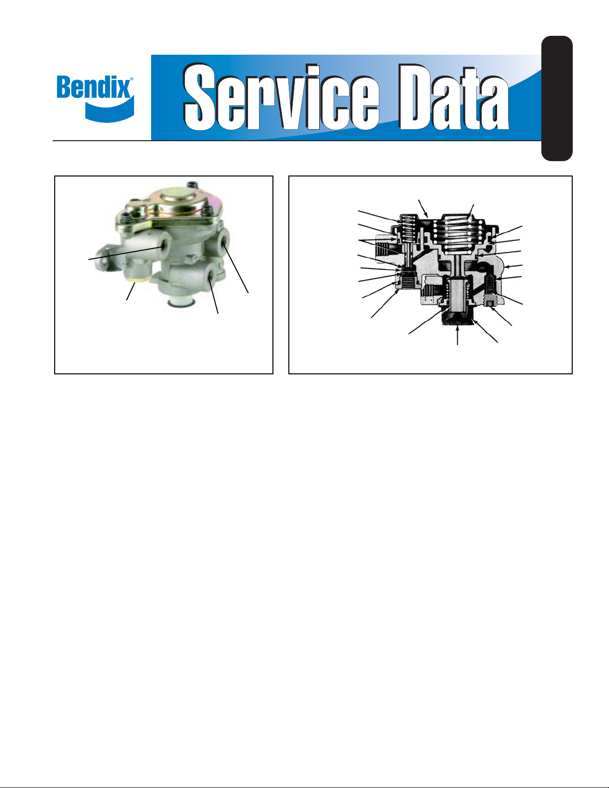
Bendix® SR-1™ Spring Brake Valve
SD-03-4508
1/4 P.T.
RES. #1
1/4 P.T.
CONTROL
FIGURE 1 - EXTERIOR VIEW
1/4 P.T.
DELIVERY
1/4 P.T.
SUPPLY
VALVE SPRING (11)
VALVE STOP (10)
FIGURE 2 - SECTIONAL VIEW
DESCRIPTION:
The SR-1™ spring brake valve is used in dual or “split” air
brake systems equipped with spring brake actuators. The
function of the SR-1™ valve is to supply a specific, limited
hold-off pressure to the spring brakes, and in the event of
loss of No. 1 service air pressure, to modulate the spring
brakes through the use of the service brake valve.
The valve has four identified 1/4" N.P.T.F. ports and a
diaphragm protected exhaust port. T wo 5/16" diameter holes
are provided in the integral mounting bracket of the valve
body . The SR-1™ valve must be mounted with the exhaust
port down toward the road surface.
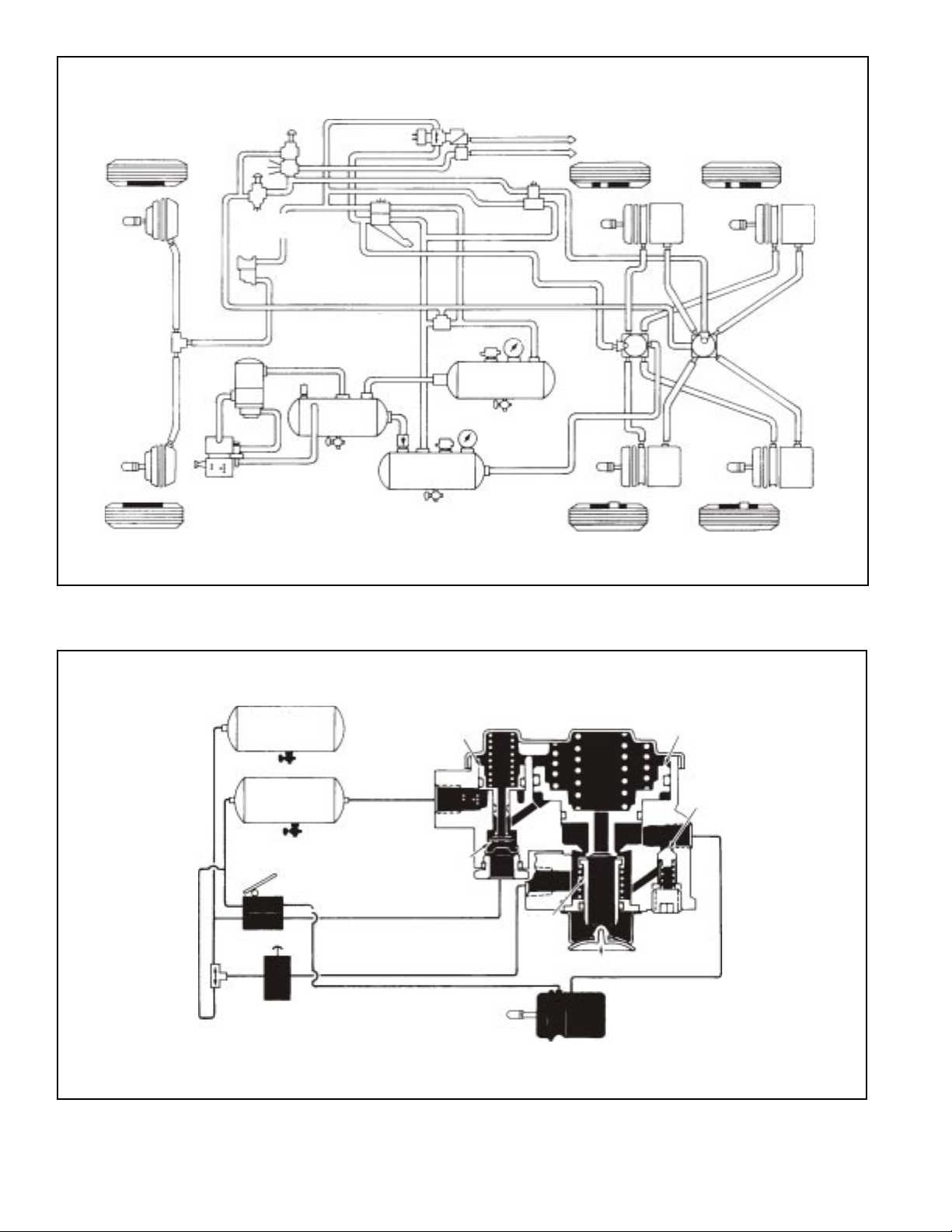
OPERATION - INITIAL AIR SYSTEM CHARGE
Upon initial charge, air from #1 & #2 service reservoirs flows
through the park control valve and enters the SR-1™ valve
supply port. Air entering the supply port flows past inlet and
exhaust valve B to the underside of piston B and out the
delivery port of the SR-1™ valve to the emergency air
connection at the spring brake actuator. Note that the springs
above piston B force it into contact with inlet and exhaust
valve B. In the position shown the exhaust is closed and the
inlet is open.
PISTON
SPRINGS (14)
(6)
COVER (5)
O-RING
(LARGE)
(SMALL) (19)
VALVE SPRING (2)
PIPE PLUG
EXHAUST
PISTON SPRING
(14)
PISTON (15)
PISTON O-RINGS
(16)
VALVE (12)
O-RING (9)
CAP NUT
(8)
COVER (13)
INLET &
EXHAUST
VALVE (7)
DIAPHRAGM
Air flowing from the No. 1 reservoir only enters the reservoir
port of the SR-1™ valve. This air remains under piston A as
system pressure builds. With No. 1 reservoir pressure below
approximately 55 P.S.I. the spring above piston A forces it
into contact with inlet and exhaust valve A causing the
exhaust to seal and the inlet to open.
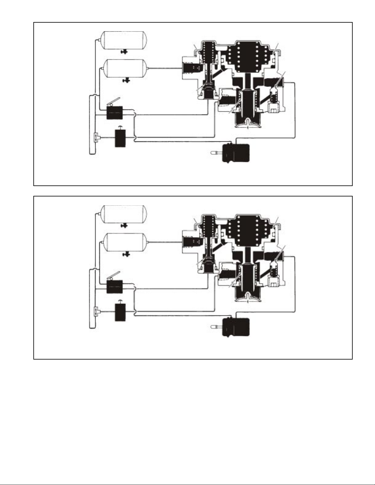
With air system pressure above approximately 55 P.S.I. in
No. 1 & 2 service reservoirs, piston A has moved against
the force of the spring above it, allowing the inlet of valve A
to close and opening the hollow exhaust passage through
piston A.
OPERATION - AIR BRAKE SYSTEM FULLY
CHARGED
When air pressure beneath piston B is approximately 95*
P .S.I., piston B rises slightly , against the force of the springs
above it, allowing the inlet of valve B to close. The exhaust
through valve B remains closed. The closing of the inlet
portion of valve B retains approximately 95* P.S.I. in the
hold- off cavity of the spring brake actuators while allowing
full air system pressure to build elsewhere.
*Note: Other spring brake hold-off pressures are supplied
according to the vehicle manufacturer’s
specifications. 95 P.S.I. was chosen only for the
purpose of explanation.
(18)
PISTON (17)
O-RING
BODY
CHECK
VALVE (4)
CHECK
(1)
1
Page 2
MODULATOR
™
PP-7
CONTROL
VALVE
PARK
CONTROL
LQ-4
™
VALVE
DS-1
DOUBLE
CHECK
VALVE
TP-3
LP-3™ INDICATOR
#2 SERVICE
RESERVOIR
™
TRACTOR PROTECTION VALVE
SB-3 SB-3
™
R-8
VALVE
™
R-8
VALVE
FIGURE 3 - PIPING DIAGRAM
#2 SERVICE
RESERVOIR
#1 SERVICE
RESERVOIR
SUPPLY
RESERVOIR
#1 SERVICE
RESERVOIR
PISTON A
INLET &
EXHAUST A
SB-3 SB-3
PISTON B
CHECK VALVE
DOUBLE
CHECK
VALVE
PARK
CONTROL
FIGURE 4 - CHARGING - BELOW 55 P.S.I.
2
SB-3
INLET
&
EXHAUST
B
EXHAUST
Page 3
#2 SERVICE
RESERVOIR
PISTON A
PISTON B
#1 SERVICE
RESERVOIR
DOUBLE
CHECK
VALVE
FIGURE 5 - SYSTEM FULLY CHARGED
#2 SERVICE
RESERVOIR
#1 SERVICE
RESERVOIR
PARK
CONTROL
INLET &
EXHAUST A
PISTON A
CHECK VALVE
INLET &
EXHAUST
B
EXHAUST
SB-3
PISTON B
CHECK VALVE
INLET &
EXHAUST A
DOUBLE
CHECK
VALVE
FIGURE 6 - NORMAL SERVICE APPLICA TION
PARK CONTROL
OPERATION - NORMAL SERVICE
RESERVOIRS 1 & 2 CHARGED
When a service application is made by actuating the dual
brake valve, air from the No. 2 delivery circuit is delivered
from the brake valve to the control port, and is stopped at
the closed inlet of valve A. No movement of the internal
components of the SR-1™ valve takes place. Air from the
No. 1 delivery circuit of the dual brake valve actuates the
service section of the spring brake actuators.
INLET
&
EXHAUST
B
EXHAUST
SB-3
OPERATION - SERVICE APPLICATION WITH
LOSS OF NO. 2 RESERVOIR PRESSURE
In the event air pressure is lost in the No. 2 reservoir, the No.
1 reservoir and the parking control valve will be protected via
the double and single check valves in the air system. A
service application of the foot brake valve in this situation
results in little or no air being delivered from the No. 2 delivery
circuit to the control port of the SR-1™ valve. No movement
of the SR-1™ valve internal components takes place. Braking
is assured because the No. 1 service reservoir is protected
by a check valve and the No. 1 delivery circuit of the dual
3
Page 4

#2 SERVICE
RESERVOIR
PISTON A
PISTON B
#1 SERVICE
RESERVOIR
INLET &
EXHAUST A
DOUBLE
CHECK
VALVE
FIGURE 7 - SERVICE APPLICATION - LOSS OF #2 RESERVOIR
PARK
CONTROL
#2 SERVICE
RESERVOIR
#1 SERVICE
RESERVOIR
PISTON A
INLET &
EXHAUST A
CHECK VALVE
INLET &
EXHAUST
B
EXHAUST
SB-3
PISTON B
CHECK VALVE
DOUBLE
CHECK
VALVE
FIGURE 8 - SERVICE APPLICATION - LOSS OF #1 RESERVOIR
PARK
CONTROL
brake valve will apply the service section of the spring brake
actuators.
OPERATION - SERVICE APPLICATION WITH
LOSS OF NO. 1 RESERVOIR PRESSURE
If air pressure in the No. 1 service reservoir falls below
approximately 55 P.S.I., the pressure beneath piston A is
insufficient to resist the spring force above and piston A
moves into contact with valve A. Initial contact between piston
A and valve A closes the hollow exhaust passage of piston
A. Continued movement of the piston opens the inlet of
valve A.
The No. 2 service reservoir and the park control valve are
protected from pressure loss by the action of the double
check valve.
INLET &
EXHAUST
B
EXHAUST
SB-3
When a service application of the dual brake valve is made,
air delivered from the No. 2 delivery circuit of the dual
brake valve enters the SR-1™ valve control port. Air entering
the control port moves past the inlet of valve A and is
conducted through a passage in the body to the underside
of piston B. The air pressure moves piston B up, opening
the exhaust of valve B. When the exhaust of valve B opens,
air pressure trapped in the emergency section of the spring
brake actuator is allowed to escape, resulting in an
emergency brake application. The air pressure released from
the spring brake is proportional to the air pressure delivered
to the control port of the SR-1™ valve by the No. 2 delivery of
the dual brake valve.
4
Page 5

#2 SERVICE
RESERVOIR
PISTON B
PISTON A
#1 SERVICE
RESERVOIR
EXHAUST A
DOUBLE
CHECK
VALVE
FIGURE 9 - PARK APPLICA TION
PARK
CONTROL
OPERATION - PARKING
If both systems #1 and #2 are intact and the park control
valve is placed in the “park” or exhaust position, the SR-1
valve supply of air pressure and the air pressure in the spring
brake actuator cavities is exhausted. The single check valve
in the SR-1™ valve assists this exhaust of air pressure by
allowing the air below piston B to flow back out the open
exhaust of the park control valve. When air pressure below
piston B has dropped sufficiently, piston B moves down,
opening the inlet of valve B and providing an additional
exhaust passage for air exhausting through the SR-1™ valve
from the spring brakes.
PREVENTIVE MAINTENANCE
Important: Review the Bendix Warranty Policy before
performing any intrusive maintenance procedures. A warranty
may be voided if intrusive maintenance is performed during
the warranty period.
No two vehicles operate under identical conditions, as a
result, maintenance intervals may vary. Experience is a
valuable guide in determining the best maintenance interval
for air brake system components. At a minimum, the SR-1
valve should be inspected every 6 months or 1500 operating
hours, whichever comes first, for proper operation. Should
the SR-1™ valve not meet the elements of the operational
tests noted in this document, further investigation and service
of the valve may be required.
SERVICE CHECKS
OPERATING CHECKS
Block all wheels and hold by means other than vehicle brakes.
Charge air brake system to governor cut-out pressure.
CHECK VALVE
INLET &
INLET &
EXHAUST
B
EXHAUST
SB-3
1. Place parking control valve in the “park” position. Observe
that the spring brake actuators apply promptly. In the
™
delivery port of the valve install a test gauge known to be
accurate. Place the parking control valve in the “release”
position. Observe that the spring brake actuators release
fully.
2. With the parking control valve in the “release” position,
note the gauge pressure reading. (Check the vehicle
manual for the correct spring brake actuator hold-off
pressure.) If the pressure reading is incorrect, the valve
must be repaired or replaced.
3. Place the parking control valve in the “park” position, the
gauge reading should drop to zero promptly. A slow
release of pressure may indicate faulty operation of the
single check valve (within the modulating valve.)
4. Place the parking control valve in the “release” position.
Locate the number one service reservoir and drain it
completely .
Apply the foot brake valve several times and note that
the pressure reading on the gauge decreases each
time the foot brake valve is applied. After several
™
applications, pressure on the gauge will drop to the point
where release of the spring brake actuators will no
longer occur.
LEAKAGE CHECK
With the air system fully charged and the parking control
valve in the “release” position, coat the exhaust port and
around the valve corner with a soap solution. Slight leakage
is permitted.
If the SR-1™ spring brake valve does not function as described
above, or leakage is excessive, it is recommended that it be
repaired or replaced with a genuine Bendix service
replacement valve.
5
Page 6

Note: A maintenance kit for the SR-1™ spring brake valve is
available from any authorized Bendix outlet. All part s
necessary for minor repair are included.
REMOVAL
1. Prior to removing the SR-1™ valve apply the parking
brakes and drain all the vehicle reservoirs.
2. Identify all air lines before disconnecting.
3. Remove the two mounting bolts from the SR-1™ valve
and remove the valve.
DISASSEMBLY (REFER TO FIGURE 2)
1. Remove the socket head pipe plug (1).
2. Remove the check valve spring (2) and the check valve
(4).
3. Remove the two phillips head screws and remove the
exhaust cover (5).
4. Separate the exhaust diaphragm (6) from the cover.
5. Remove the inlet and exhaust valve assembly (7).
6. Remove the inlet and exhaust valve cap nut (8) and
separate the cap nut o-ring (9).
7. Remove the valve stop (10) valve spring (11) and inlet
and exhaust valve (12).
8. Remove the four phillips head screws and lockwashers
that secure the cover to the body . Caution: the cover is
under a spring load, and should be held while removing
the screws.
9. Remove the cover (13) and the three piston springs
(14). Note: Some SR-1™ valve piece numbers have one
large piston spring.
10.Remove the small piston (15) and the small and large
o-rings (16).
11.Remove the large piston (17). Remove piston o-rings
(18) & (19).
CLEANING & INSPECTION
Note: All torques specified in this manual are assembly
torques and can be expected to fall off, after
assembly is accomplished. Do not retorque after
initial assembly torques fall.
1. Assemble the check valve (4), and valve spring (2) and
install in body.
2. Apply pipe sealant to the socket head pipe plug (1) and
install in the body. Tighten to 130-170 inch pounds
torque.
3. Install inlet and exhaust valve assembly (7) in valve body .
4. Secure the exhaust cover (5) with two 10-24 phillips
screws and lockwashers. Tighten to 20-30 inch pounds
torque.
5. Install exhaust diaphragm (6) into the exhaust cover .
6. Place inlet exhaust valve (12) in the body. Install the
valve spring (1 1) and valve stop (10).
7. Install o-ring (9) on cap nut and install cap nut (8) in
body. Tighten to 100-125 inch pounds torque.
8. Install the small and large o-rings (16) on the small
diameter piston (15) and install piston in the body .
9. Install large o-ring (18) and small o-ring (19) on the large
diameter piston and install piston in the body .
10.Install the piston springs (14) in their respective pistons.
1 1. Secure the cover to body using four 1/4"-20 phillips head
screws and lockwashers. Tighten to 50-80 inch pounds
torque.
TESTING THE REBUILT SR-1™ SPRING BRAKE
VALVE
T est the rebuilt SR-1™ spring brake valve by performing the
operation and leakage test outlined in the “Service Checks”
section of this manual.
WARNING! PLEASE READ AND FOLLOW
THESE INSTRUCTIONS TO AVOID
PERSONAL INJURY OR DEATH:
Inspect all parts for excessive wear or deterioration.
Inspect the valve seats for nicks or burrs.
Check the springs for cracks or corrosion.
Replace all rubber parts and any part not found to be
serviceable during inspection. Use only genuine Bendix
replacement parts.
ASSEMBLY (REFER TO FIGURE 2)
Prior to assembly of the SR-1™ spring brake valve, lubricate
all o-rings, o-ring grooves, and piston bores with Bendix
silicone lubricant BW-650-M piece number 291 126.
6
When working on or around a vehicle, the following
general precautions should be observed at all times.
1. Park the vehicle on a level surface, apply the
parking brakes, and always block the wheels.
Always wear safety glasses.
2. Stop the engine and remove ignition key when
working under or around the vehicle. When
working in the engine compartment, the engine
should be shut off and the ignition key should be
removed. Where circumstances require that the
engine be in operation, EXTREME CAUTION should
be used to prevent personal injury resulting from
contact with moving, rotating, leaking, heated or
electrically charged components.
Page 7

3. Do not attempt to install, remove, disassemble or
assemble a component until you have read and
thoroughly understand the recommended
procedures. Use only the proper tools and observe
all precautions pertaining to use of those tools.
4. If the work is being performed on the vehicle’s air
brake system, or any auxiliary pressurized air
systems, make certain to drain the air pressure from
all reservoirs before beginning ANY work on the
vehicle. If the vehicle is equipped with an AD-IS
air dryer system or a dryer reservoir module, be
sure to drain the purge reservoir.
5. Following the vehicle manufacturer’s
recommended procedures, deactivate the electrical
system in a manner that safely removes all
electrical power from the vehicle.
6. Never exceed manufacturer’s recommended
pressures.
7. Never connect or disconnect a hose or line
containing pressure; it may whip. Never remove a
component or plug unless you are certain all
system pressure has been depleted.
8. Use only genuine Bendix® replacement parts,
components and kits. Replacement hardware,
tubing, hose, fittings, etc. must be of equivalent
size, type and strength as original equipment and
be designed specifically for such applications and
systems.
9. Components with stripped threads or damaged
parts should be replaced rather than repaired. Do
not attempt repairs requiring machining or welding
unless specifically stated and approved by the
vehicle and component manufacturer.
10. Prior to returning the vehicle to service, make
certain all components and systems are restored
to their proper operating condition.
®
7
Page 8

8
BW1589 © 2004 Bendix Commercial Vehicle Systems LLC. All rights reserved. 3/2004 Printed in U.S.A.
 Loading...