


AVS-425
11
11
18
4
6
8
4
9
9
4
2
1
13
17
7
10
10
12
12
4
Fig. 1
2
Fig. 2
18
3
16
1 x
Ordering part #
CHFE 007
S
heet nr.
ALLEN WRENCH
4 x
Ordering part #
MHS 174
Item #
4
8
x
Ordering part #
M
HGP 021
Item #
1
0
2
x
Ordering part #
M
HAF 030
Item #
2
4
x
O
rdering part #
MHS 052
Item #
9
1 x
Ordering part #
CHPL 001
Sheet nr.
PHILLIPS DRIVER
4 x
Ordering part #
Item #
2
x
Ordering part #
F
VPL 005
VTPL 001
Item #
12
1
6
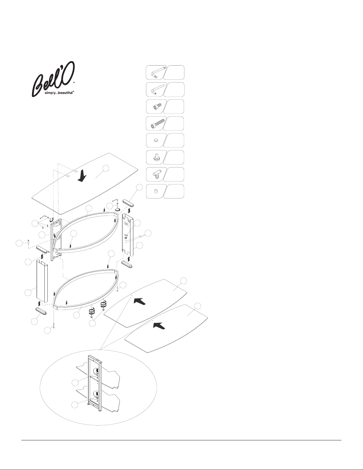
AVS-425
ASSEMBLY INSTRUCTIONS
NOTE: TWO PEOPLE ARE RECOMMENDED TO ASSEMBLE THIS UNIT.
THIS FURNITURE SHOULD BE ASSEMBLED ON A SOFT SURFACE.
A. REMOVE the two oval metal frames from the carton and place the TOP frame (7), identified by
the “TOP” sticker, to the side.
etal inserts on the bottom center of the frame, and
m
hreaded insert.
t
PLACE the BOTTOM frame (1) with the leveling feet (2) on the floor facing towards the front.
B.
EING CAREFUL NOT TO SCRATCH the BOTTOM frame,
Bell’O International Corp.
711 Ginesi Drive
Morganville, NJ 07751-1235
Customer Service: (888) 235-7646
E-mail: support@bello.com
Web: www.bello.com
B
nd LEFT side leg (6) over the BOTTOM frame as shown in Fig.1. with the “TOP” sticker on the
a
egs pointing upwards and the shelf support clips facing towards the opposite leg.
l
C. BEING CAREFUL NOT TO SCRATCH the TOP frame, PLACE the TOP frame (7) into the leg
cutouts at the top of both legs, so that the Bell’O logo is facing forward near the right leg (3).
D. SECURE the TOP frame (7) to both legs, using two of the long screws (4) and the supplied
Allen wrench.
NOTE: DO NOT FULLY TIGHTEN THE SCREW AT THIS POINT.
E. CAREFULLY LIFT TOP frame and both legs off of the BOTTOM frame, and TURN the partially
assembled table over and GENTLY place it on the floor, so that it is resting on the TOP frame
and the legs are facing upwards.
F. BEING CAREFUL NOT TO SCRATCH the BOTTOM frame, PLACE the BOTTOM frame (1)
nto the leg cutouts at the exposed ends of both legs, so that the leveling feet (2) are facing
i
pwards.
ECURE the BOTTOM frame (1) to the legs with two long screws (4) and FULLY
u
S
IGHTEN
T
eg.
l
sing the supplied Allen wrench. INSERT the plastic caps (18) into the end of each
u
G. CAREFULLY turn the table over so that it is resting on the BOTTOM frame. GO BACK and
FULLY TIGHTEN screws that secure the legs to the frame. INSERT the plastic caps (18) into
the end of each leg.
PLACE the CMS®(Cable Management System®) post (8) upright against the rear of the frame
H.
as shown in Fig.1.
MUST BE FACING UPWARDS.
I. ALIGN the top and bottom holes of the CMS®post with the holes located on the rear of TOP and
BOTTOM frames (1) and (7).
the Allen wrench.
CAREFULLY MOVE and POSITION the furniture to the location it will occupy in the room when
J.
fully assembled and in use.
APPLY the four rubber glass pads (10) to the upper sides of the TOP (7) and BOTTOM frame
K.
(1) as shown in Fig. 1.
L. CAREFULLY SLIDE one of the two smaller glass shelves (11) onto the BOTTOM frame (1) with
the glass shelf locking pin hole inserted through the bottom slot of the CMS
glass shelf in place, from the rear of the CMS
locking pin (12) as shown in Fig.2.
INSERT the supplied set screws (16) part of the way into the glass shelf clips (13) and
M.
partially tighten them using the supplied Phillips driver (14) or your own screw driver,
leaving enough room to slide the shelf into the clip.
of the two smaller glass shelves (11) through the shelf support clips (13) located
on the center of the two side legs (3) and (6), so that the shelf locking pin hole
PATENT PENDING
Bell’O International Corp. will not be responsible for failure to assemble as directed or for the improper assembly, use or handling of this stand. © 2005 BELL’O INTERNATIONAL, LLC
shelf locking pin (12) as shown in Fig.2.
clips (13) using the supplied set screws (16) and Phillips driver (14).
OVERTIGHTEN.
N. CAREFULLY position and place the top glass shelf (17), the largest of the three shelves, and
the one with the two SIL
discs are facing towards the rear and
(8). Working from the REAR of the furniture, and from the underside of the top frame of the
®
post, SECURE the
CMS
using the supplied
ANT NOTE: WHEN IN USE, THIS FURNITURE MUST BE PLACED ON A FLAT AND
IMPORT
LEVEL SURFACE. ADJUST THE TWO FRONT LEVELING FEET UNTIL THE FURNITURE
RESTS SQUARELY ON THE FLOOR.
: REMOVE
ANT
T
IMPOR
PRIOR TO MOVING THE ASSEMBLED UNIT. DO NOTATTEMPT TO MOVE THE ASSEMBLED
FURNITURE AFTER THE GLASS SHELVES HAVE BEEN INSTALLED, AND/OR WHEN THERE
IS EQUIPMENT
LOCA
BECOME UNSECURE AND FALL. MAKE SURE THAT THE FRONT OF THE TV IS
POSITIONED A FEW INCHES BACK FROM THE FRONT OF THE TOP GLASS. WHEN IN USE,
THIS FURNITURE MUST
ALWAYS PLACE THE HEAVIEST EQUIPMENT ON THE BOTTOM SHELF.
SELECT the BOTTOM frame (1), identified by the two threaded
CREWthe leveling feet (2) into the
S
OSITIONthe RIGHT side leg (3)
P
NOTE: THE TWO HOLES IN THE TOP FRAME OF THE CMS®POST
SECURE the CMS®to the frames using two short screws (9) and
®
®
post, using the supplied ‘T’-shaped plastic shelf
post (8). LOCK the
CAREFULLY SLIDE the second
®
is inserted through the slot of the CMS
place, from the rear of the CMS
post (8). LOCK the glass shelf in
®
post, using the supplied ‘T’-shaped plastic
SECURE tightly into the glass shelf
DO NOT
VER DISCS, onto the top of the assembled furniture so that two silver
ALIGNED with the holes in the TOP of the CMS®post
glass shelf (17) to the CMS
OP
T
®
post with 2 smaller screws (9)
Allen wrench.
ALL GLASS, TV AND OTHER EQUIPMENT FROM THE FURNITURE
THE FURNITURE
TED ON
BE PLACED ON
AS THIS MAY CAUSE THE SHELVES TO
T AND LEVEL SURFACE.
FLA
A
v_01M
 Loading...