


AVS-422
1
9
10
12
4
3
2
11
1
3
5
8
8
7
6
6
fig. 3
fig. 2
fig. 1
Ordering part #
VTAC 078
Item #
6
O
rdering part #
VTPL 001
Item #
1
3
Ordering part #
PDPL 029
Item #
8
x
Ordering part #
PDPL 021
Item #
7
fig. 4
2.5"
fig. 5
8
8
8
Ordering part #
CMPT 004
S
heet nr.
Philips Screwdriver
O
rdering part #
C
MPT 006
Sheet nr.
Allen Wrench
DESIGN PATENT 489,548
Bell’O International Corp. will not be r
esponsible for failur
e to assemble as dir
ected or for the improper assembly, use or handling of this stand.
© 2002 BELL
’O INTERNA
TIONAL, LLC
Bell’O International Corp.
711 Ginesi Drive
Morganville, NJ 07751-1235
Customer Service: (888) 235-7646
E
-mail: support@bello.com
Web: www.bello.com
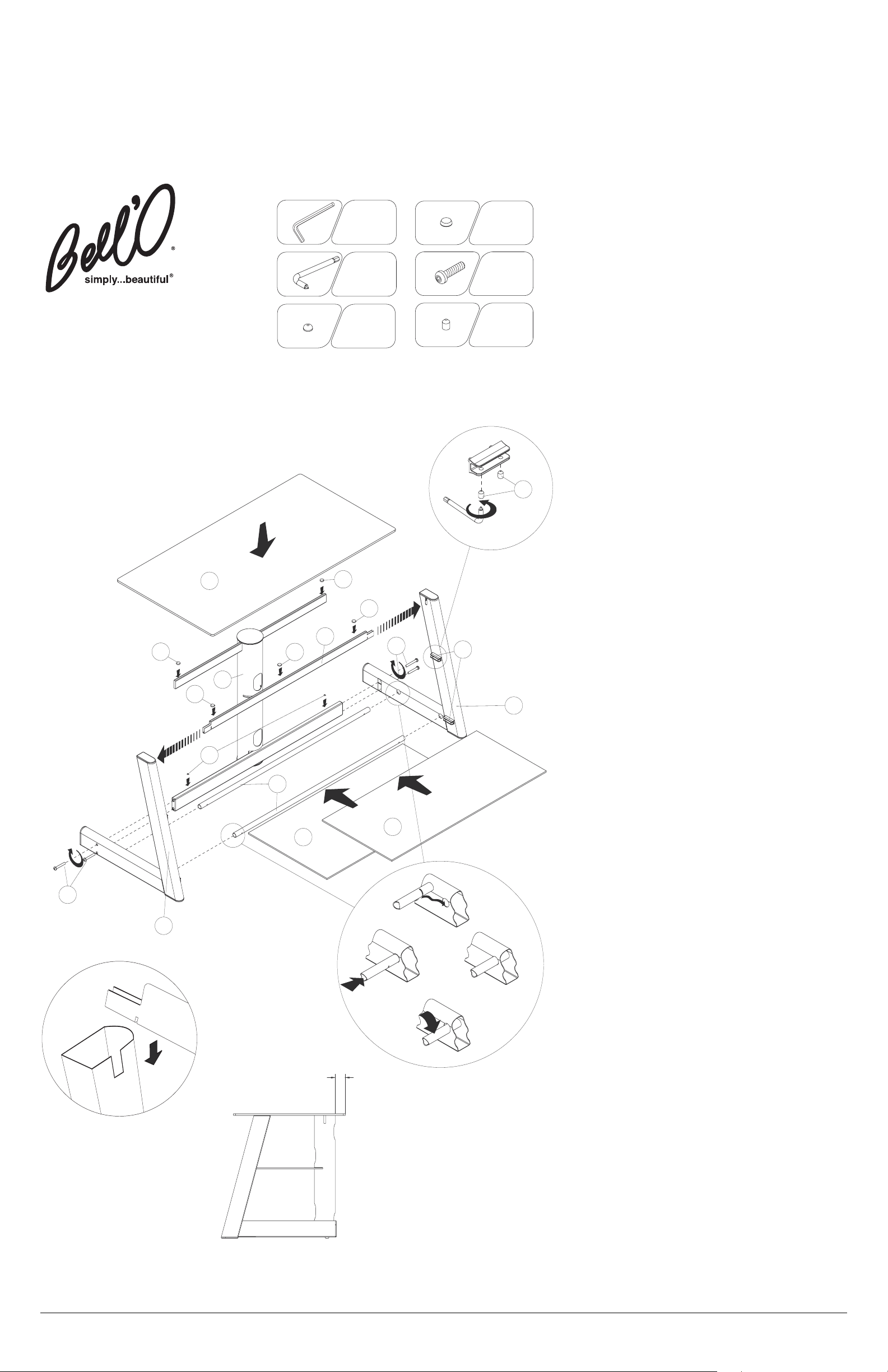
AVS-422
ASSEMBLY INSTRUCTIONS
NOTE: Two people are recommended to assemble this unit.
P
LACE
t
he rear CMS
®
(
Cable Management System) post (3)
u
pright on the floor with the shelf slot facing towards the front as
shown in Fig. 1.
A
LIGN
t
he two holes located on the CMS
®
p
ost lower rear support
bar end with the matching holes located towards the rear on the
b
ottom of the left side frame (1).
I
NSERT
t
wo screws (6) and
S
ECURE
t
he side frame (1) to the CMS
®
p
ost bar (3) using the
supplied
Allen wrench, as shown in Fig. 1.
DO NOT FULL
Y
T
IGHTEN THE SCREWS AT THIS POINT.
I
NSERT
t
he two round bottom shelf support bars (4) into the
holes on the left side frame leg (1) making sure that the cut-out
slots on either end of the support bars (4) are facing
DOWNWARDS. PUSH downward on the bars until the slot
s
naps into the side frame as shown in Fig. 2.
INSERT the upper front support bar (5) into the cut-outs located
on the inside top of the left side frame (1) so that the cut-out slot
near each end of the upper front support bar is facing down as
s
hown in fig. 5.
NOTE: When positioned correctly, the cut-out slot in the upper
f
ront support bar will fit over the inner edge of each side frame
with the bar ends positioned inside the top of the frame.
REPEAT steps B and C above for the right side frame (2) making
sure that the right side of the support bars (4) are securely
snapped into place and the upper front support bar is positioned
c
orrectly in the right side frame.
D
O NOT FULLY TIGHTEN THE
SCREWS AT THIS POINT.
PLACE the small glass pads (7) onto the lower rear glass support
bar of the CMS
®
post (3). PLACE the larger and taller glass pads
(8) onto the upper rear glass support bar of the CMS
®
post (3)
and front upper glass support bars.
MOVE the assembled stand into the position it will occupy in the
room PRIOR to adding the glass shelves, TV, or other equipment.
CAREFULL
Y
PLACE
the bottom (middle sized) shelf (9) into
position so that the shelf rear slides into the cut-out slot on the
CMS
®
post (3) , and secure tightly into the glass shelf clips (1
1)
using the supplied set screws (13) and plastic screwdriver (14) as
shown in Fig. 3. NOTE: It won’t be possible to place the glass
shelves into position unless the support bars (4) are securely
snapped into place.
CAREFULLY PLACE the center (smallest sized) shelf (10) into
position so that the shelf rear slides into the cut-out slot on the
CMS
®
post (3) , and secure tightly into the glass shelf clips (11)
using the supplied set screws (13) and plastic screwdriver (14)
as shown in Fig. 3.
NOW GO BACK AND TIGHTEN the screws to secure the side
frames (1) and (2) and the CMS
®
post bar (3) using the supplied
Allen wrench.
CAREFULLY PLACE the top (largest sized) shelf (12) into
position so that the shelf rear rests on the rear support bar and
top of the CMS
®
post (3). NOTE: It is recommended that the top
extends out exactly 2.5” from the end of CMS
®
post (3), as
shown in Fig. 4.
IMPORTANT: REMOVE ALL GLASS, TV AND OTHER
EQUIPMENT FROM THE STAND PRIOR TO MOVING THE
ASSEMBLED UNIT. DO NOT ATTEMPT TO MOVE THE
ASSEMBLED ST
AND AFTER THE GLASS SHELVES HAVE
BEEN INSTALLED, AND/OR WHEN THERE IS EQUIPMENT
LOCATED ON THE STAND AS THIS MAY CAUSE THE
SHELVES TO BECOME UNSECURE AND FALL. MAKE SURE
THAT THE FRONT OF THE TV IS POSITIONED A FEW INCHES
BACK FROM THE FRONT OF THE TOP GLASS. WHEN IN USE,
THIS FURNITURE MUST BE PLACED ON A FLAT AND LEVEL
SURFACE.
ALWAYS PLACE THE HEAVIEST EQUIPMENT ON THE
BOTTOM SHELF.
Italian Designed
v_02INT
2 x
O
rdering part #
PDPL 021
Item #
7
1 x
Ordering part #
C
MPT 004
S
heet nr.
Philips Screwdriver
1 x
O
rdering part #
CMPT 006
Sheet nr.
A
llen Wrench
4 x
Ordering part #
VTAC 078
Item #
6
8 x
O
rdering part #
VTPL 001
Item #
13
5 x
O
rdering part #
PDPL 029
Item #
8
2 x
O
rdering part #
PDPL 021
I
tem #
7
1 x
O
rdering part #
CMPT 004
Sheet nr.
Philips Screwdriver
1 x
Ordering part #
CMPT 006
Sheet nr.
Allen Wrench
A
.
B.
C.
D.
E.
F.
G.
H.
I.
J.
K.
 Loading...