


23WL46G 30WL46G
L6B TFTLCD TV
SERVICE MANUAL
CONTENTS |
PAGES |
Safety instructions |
1 |
Technical specifications |
2 |
Panel Specification |
3 |
Back appearance of TV |
5 |
Interconnectıon Diagram |
5 |
Block diagram |
6 |
Block diagram of power supply |
7 |
Service mode |
8 |
Service Mode items and values |
10 |
Data sheet of important IC’s and parts |
11 |
Recommended Part List |
23 |
Frequency list of channels |
25 |

SAFETY PRECAUTIONS
GENERAL GUIDELINES
1.It is advised to insert an isolation transformer in the AC supply before servicing a hot chassis.
2.Always use the manufacturer’s replacement safety
components. The critical safety components marked with  on the schematics diagrams should not be by other substitutes. Other substitute may create the electrical shock , fire or other hazards. Take attention to replace the spacers with the originals. Furthermore where a short circuit has occurred , replace those components that indicate evidence of overheating.
3.After servicing , see that all the protective devices such as insulation barriers, insulation papers, shields and isolation R-C combinations are correctly installed.
4.When the receiver is not being used for a long time of period of time , unplug the power cord of the Adaptor from the AC outlet.
Color TFT LCD Module is very sensitive both electrically and physically.Users, therefore, are requested to follow the “Guidance of handling color TFT LCD Module”on the followings.
1 -Be careful not to make scratch on the polarizer.
Surface of polarizer is soft and can be physically damaged easily.Please do not touch, push or rub polarizer surface with materials over HB hardness.
2 - Keep clean the surface.
Please wear rubber glove when touch the surface of LCD screen. Please use soft and anti-static material as cleaner.
3 -Keep out of water.Water on/in the LCD may cause electrical short or corrosion. Please wipe out
dry or water carefully.
4 -Prevent swift Temperature & Humidity change.Instantaneous temperature and/or humidity change can make dew or ice which cause nonconformance such as malfunction.
5 - High temperature & high humidity reduce the life-time.
LCD is not proper to be used at high temperature and high humidity. Please keep specified temperature and humidity condition.
6 - Keep out of Corrosive Gas.Corrosive gas effect the polarizer and the circuit chemically and cause defects accordingly.
There are electro-static sensitive components such as CMOS in LCD Module. Please earth human body when handle the LCD.In addition, please do not touch the interface connector pin with bare.
8 - Do not operate for a long time under the same pattern
Operating LCD for a long time under the same pattern can cause image persistence and can damage it. Please follow following guidance.
1.Turn the power off when do not use.
2.Change the pattern periodically.
LEAKAGE CURRENT COLD CHECK
1.Unplug the AC cord and connect a jumper between the two prongs of the plug.
2.Turn the receiver’s power switch.
3.Measure the resistance value with an ohmmeter, between the jumpered AC plug and each exposed metallic cabinet part on the receiver. When the exposed metallic part a return path to the chassis the reading should be between 4Mohm and the 20Mohm. When the exposed metal does not have a return path to the chassis, the reading must be infinite.
LEAKAGE CURRENT HOT CHECK
1.Plug the AC cord directly in to the AC outlet. Do not use an isolation transformer for this check.
2.Connect a 2Kohm 10W resistor in series with an exposed metallic part on the receiver and an earth, such as a water pipe.
3.Use an AC voltmeter with high impedance to measure the potential across the resistor.
4.Check each exposed metallic part and check the voltage at the each point.
5.Reverse the AC plug at the outlet and repeat each of the above measurements.
6.The potential at the any point should not exceed 1.4 Vrms. In case a measurement is outside the limits specified , there is the possibility of a shock hazard , and the receiver should be repaired and rechecked before it is returned to the customer.
HOT CHECK CIRCUIT
|
AC-Voltmeter |
TO INSTRUMENTS |
|
EXPOSED |
Water pipe |
METALLIC PARTS |
|
|
(earth) |
2 K Ohm
7- Electrostatic discharge can make Damage
L6B TECHNICAL SPECIFICATION
Receiving System |
|
PAL B/G+I+D/K SECAM L/L' |
|
Comb Filter |
|
Adaptive 4H\2H |
|
LTI, CTI Filters |
|
+ |
|
|
DVI 1.0 Compliant |
+ |
|
DVI Receiver |
Resolution |
VGA to SXGA |
|
|
2 Pixel \ Clk Support |
+ |
|
Gamma Correction |
|
8 to 10-bit LUT |
|
PIP\PAP\POP\PAT |
|
+ |
|
OSD |
|
Graphics Based 8-bit\pixel |
|
|
Level (1.5, 2.5, Teleweb) |
Teletext 1.5 |
|
Teletext |
Type (Fast\Top\Simple) |
Simple, Fast, Top |
|
|
Page Memory |
800p |
|
WSS |
|
+ |
|
VPS\PDC |
|
+ |
|
|
4:3 |
+ |
|
|
16:9 |
+ |
|
Picture Formats |
14:9 |
+ |
|
(4:3, 16:9, 14:9, Panorama, LetterBox, |
Panorama |
+ |
|
Subtitle) |
Letterbox |
+ |
|
|
Subtitle |
+ |
|
|
Zoom |
+ |
|
WSS (Wide Screen Signalling) |
|
+ |
|
ATS (Automatic Tuning System) |
|
Frequency Search |
|
Manual Search |
|
Channel Table Search |
|
Number of Program Storage |
|
+ |
|
No Ident Timer |
|
+ |
|
Picture Freeze |
|
+ |
|
Equalizer |
|
+ |
|
AVL (Automatic Volume Level) |
|
+ |
|
Sound Status Memory |
|
+ |
|
Picture Status Memory |
|
+ |
|
Swap |
|
+ |
|
Child Lock |
|
+ |
|
Program Lock |
|
+ |
|
Picture Format Switching Tru Pin 8 |
|
+ |
|
Auto RGB Detect Tru Pin 16 |
|
+ |
|
Timer |
Off Timer (Sleep Timer) |
+ |
|
On Timer |
+ |
||
|
|||
Picture Smart (User, Soft, Natural, Rich) |
|
+ |
|
|
|
|
|
Sound Smart (User, Music, Sports, Cinema, |
|
+ |
|
Speech) |
|
||
|
|
||
Scart2 Out Selectable |
|
+ |
|
S-Video Input Through Scart2 |
|
+ |
|
Audio Output Power |
|
2x5W for 22"W, 23"W |
|
|
2x10W for 26"W |
||
RMS in Max at 10% THD) |
|
||
|
2x10W for 30"W |
||
|
|
||
Stereo (German A2, Nicam, BTSC) |
|
German A2, Nicam |
|
S-video In (DIN) |
1 |
|
|
AV In (3 RCA) |
1 |
|
|
AV Out (3 RCA) |
1 |
|
|
PC Audio (L, R) |
1 |
|
|
D-Sub 15 |
1 |
|
|
Headphone |
1 |
|
|
CVBS In |
4 |
|
|
Y\C In |
1 |
|
|
DVI In |
YES |
|
|
CVBS Out |
4 |
|
PANEL SPECIFICATION
Sizes |
22" |
23" |
|
26" |
|
27" |
30" |
|
32" |
|
|
|
|
|
|
|
|
|
|
Manufacturer |
Samsung |
Samsung |
LG- |
Samsung |
LG- |
Chimei |
Chimei |
AUO |
|
|
|
Philips Hannstar |
Philips |
AUO |
|
LG-Philips |
|
|
|
|
|
|
|
|
|
|
|
|
|
Interface |
Single LVDS |
Single LVDS |
|
Singlel LVDS |
|
Singel LVDS |
Single LVDS |
|
Single LVDS |
|
|
|
|
|
|
|
|||
Resolution |
WXGA (1280x720) |
WXGA (1280x768) |
WXGA (1280x768) |
WXGA (1280x720) |
WXGA (1280x768) |
WXGA (1280x768) |
|||
|
|
|
|
|
|
|
|
|
|
Brightness (cd/m2)>= |
450 |
450 |
|
450 |
|
550 |
550 |
|
450 |
|
|
|
|
|
|
|
|
|
|
Contrast>= |
500 |
400 |
|
400 |
|
600 |
600 |
|
700 |
|
|
|
|
|
|
|
|
|
|
Response Time |
25 |
25 |
|
25 |
|
25 |
25 |
|
23 |
(Tr+Tf) msec =< |
|
|
|
||||||
|
|
|
|
|
|
|
|
|
|
Viewing Angle |
85/85 85/85 |
85/85 85/85 |
|
85/85/85/85 |
85/85/85/85 |
85/85/85/85 |
85/85/85/85 |
||
R\L\H\L>= |
|
||||||||
|
|
|
|
|
|
|
|
|
|
Adaptor İnput |
15V |
24V |
|
Built-in TV |
Built-in TV |
Built-in TV |
|
Built-in TV |
|
|
|
|
|
|
|
|
|
|
|
PoweR consumptions |
100W |
100W |
|
120W |
120W |
140W |
|
180W |
|
|
|
|
|
|
|
|
|
|
|
St-By Power |
<4W |
<4W |
|
<4W |
|
<4W |
<4W |
|
<4W |
Consumption |
|
|
|
||||||
|
|
|
|
|
|
|
|
|
|
Input Range |
100V-240V/50- 60Hz |
100V-240V/50- 60Hz |
100V-240V/50- 60Hz |
100V-240V/50- 60Hz |
100V-240V/50- 60Hz |
100V-240V/50- 60Hz |
|||
|
|
|
|
|
|
|
|
|
|

BACK SIDE APPEARANCES
CONTROL |
BOARD |
SPEAKERS 
POWER
SWITCH
220VAC INPUT 
LED/IR BOARD
POWER SUPPLY MAIN BOARD
CHASSIS
NOTE: LOCATION AND THE SHAPE OF IR /LED BAORD, CONTROL BOARD AND MAIN SWITCH BOARD MAY CHANGE ACCORDING TO THE COSMETIC OF THE TV AND SIZE

TO PANEL
MAIN CHASSIS |
|
JP453 |
|
JP452 |
JP451 |
||
|
|||
S150 |
|
|
|
SPEAKER |
|
|
|
S2 |
S550 |
|
|
TO |
|
||
|
|
||
PANEL |
|
|
|
S350 |
|
|
|
S50 |
|
JP450 |
|
TO HEADPHONE JACK |
|
|
|
IR RECEIVER/LED |
KEY BOARD |
|
|
MODULE |
MODULE |
|
CN1
POWER
SUPPLY
MODULE
CN3 |
CN2 |
MAIN POWER
SWITCH
MODULE
220V AC
INPUT
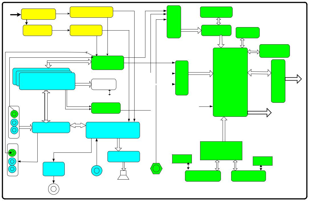
L6B BLOCK DIAGRAM
RF In |
Tuner-Main |
IF IC TDA9886T |
QSS-Main |
|||
|
|
|
|
|||
|
Tuner-PIP |
IF IC TDA9886T |
||||
|
QSS-PIP |
|||||
AV-Out Video |
|
|
PIP-Video |
Main-Video |
||
|
|
|
|
|
||
AV4 Video-In |
|
|
|
|
|
|
|
|
|
|
|
Video Switch |
|
|
|
Video In/Out |
|
TDA6415C |
|
|
|
SCART 1 2 3 |
|
Pin 8 Switch |
|
||
|
|
|
|
|
PCF8591 |
|
|
|
In/Out-Audio |
I2C Communication |
|
||
|
|
SC1-SC2 RGB |
|
RGB Switch |
|
|
|
|
|
|
|
||
|
|
|
|
|
|
|
|
AV4 |
|
|
|
PI5V30 |
|
|
|
|
|
|
|
|
|
Audio-In |
|
|
|
|
|
|
Audio-Switch |
|
AUDIO PROCESSOR |
|||
|
|
TDA6420 |
Audio |
|||
|
|
|
MSP3410D |
|
||
|
Out Audio |
|
In-Out |
|
|
|
|
|
|
|
|
||
|
|
|
|
Audio Amplifier |
||
|
AV |
|
|
|
||
|
|
|
|
TA2024 |
||
|
|
|
|
|
||
Headphone
Amp.
TDA1308
PC DVI Audio -In
Speaker
Headphone Jack
Video-Main
SAA7118MP
Video Decoder
Multi Standard
SDRAM
MT48LC16M
16 Bit
YUV PW1231
De-Interlacer EEPROM 24C64
24 Bit RGB
Flash Memory
AM29VL160
|
|
|
|
Video-PIP |
||
|
|
|
|
|
|
Multi Standard Video Decoder SAA7118MP |
RGB |
|
|
|
|
||
|
|
|
|
|||
Scart |
|
|
|
|
|
|
|
|
|
|
|
|
|
SVHS Y/C
EEPROM 24LC21
16 Bit |
PW181 |
|
IMAGE |
|
|
YUV |
PROCESSOR |
|
|
De-Interlacer |
Progressive |
|
Scaler |
or Intrelaced |
|
OSD |
24 Bit Dual |
|
RGB ,HS,VS |
|
|
Micro-Cont. |
|
|
DE,PCLK |
|
|
Gamma Corr. |
|
|
|
IR In
48 Bit RGB VS/HS
Dual İnterface for
FPD
AD9887
|
EEPROM |
|
RGB HS/VS-In |
24LC21 |
|
DVI Input |
||
|
SVHS Socket |
D-SUB 15 socket |
DVI Socket |
|
LVDSTransmitter DS090C385 |
TO THE |
|
|
|
PANEL |
Stand by
LED’s
Reset
Mute
B/L Enable
Digital Dim
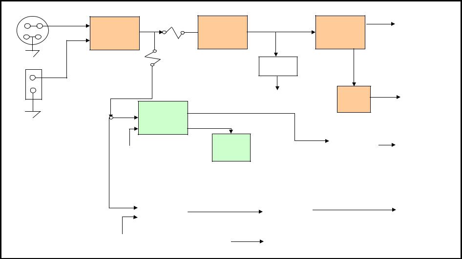
L6B POWER SUPPLY BLOCK DIAGRAM (MAIN CHASSIS)
J450
DC_IN
GND
S450
GND
U451 |
12V |
F450 |
(5V) |
|
FDS9933A
F451
12V
U452
FDS9933N
STAND_BY
U454 |
+5V_STBY |
LM2576
VOLTAGE
DOUBLER
'33V
12V_AMP
+5V
U457
NCP1117  +3,3V
+3,3V
+2,5V_STBY
U458
NCP1117
+3,3V_STBY
U450 +1,5V_STBY NCP117
U456 |
+8V |
LM317 |
|
|
|
|
U453 |
+12V |
U455 |
|
PANEL_POWER |
|
|
FDS9933N |
|
|
LM2576 |
|
|
|
|
|
|
|
||
|
|
|
|
|
|
|
|
|
|
|
|
|
|
PNL_EN |
|
|
+12V_INVERTER |
|
||
L6B SERVICE MENU
1. Activating the Service Menu
When the menu is on the screen press ‘9’, ‘3’, ’0’, ’1’ on the remote controller. This will activate the service menu.
2.Service Menu Structure
The service menu has three items: display, calibre and version
2.1Display
Display item has seven options: a- Panel
Panel option gives information about the current panel resolution. It is a read only option and can not be set.
b- Power on time
Power on time gives information about the last update time of the SW running. It is a read only option and can not be set.
c- Backlight on time
Backlight on time option reserved.
d- Scart prescale
Scart prescale option sets the prescale values for the input sounds entering the scart input of the MSP(Micronas Sound Processor). Changing this value you can adjust the level of the output sound going to loudspeakers for all the sources except the Tuners. The range is between 0 and 100.
e- nicam prescale
Nicam prescale option sets the prescale values for the Nicam standard sounds for tuner inputs. Changing this value you can adjust the level of the output sound going to loudspeakers for Nicam sounds entering the analog sound input of MSP. The range is between 0 and 100.
f- fm/am prescale
fm/am prescale option sets the prescale values for the FM/AM standard sounds for tuner inputs. Changing this value you can adjust the level of the output sound going to loudspeakers for FM/AM sounds entering the analog sound input of MSP. The range is between 0 and 100.
g- Agc(Automatic Gain Control) adjust
Agc adjust option sets the input voltage going to IF decoder AGC pin. Changing this value you can adjust this voltage for optimum Tuner performance. The range is between 0 and 31.
h- R/G/B Brightness/Contrast: These are used for color bias adjustment. The range is Between 0 and 255
2.2Calibre
Calibre item has nine options: a- video format
Video format option force the video format to the desired format. Selectable formats are Auto, Pal, NTSC and SECAM.
b- colorspace
Colorspace option gives the information about the video input colorspace input to PW181 IC. Do not change this value unless an error occurred in the colors displayed.
c- test pattern
This option activates the internal pattern of PW181 IC. There are 3 choices: none, vert bars, solid color. None will deactivate the internal pattern. Vert bars choice activates the bar pattern for the selected color component. Solid color activates the solid pattern with one color selected in color component and also you can change the level of the color by solid field level.
d- Color components:
This option selects the color for the internal pattern of PW181 IC. There are 4 choices: all, red, green and blue. If you choose all, you can see the white pattern and if you choose one of the other choices you can see the test pattern with the selected color.
e- solid field level
This option will adjust the level of the colors for the test pattern. The range is betwwen 1 and 64.
f- Initial ATS
This option will enable or disable the Initial setup for the TV. Setting this option to On, the TV will open from the Quick setup menu. Setting this option to Off will disable this option.
g- factory reset
Factory reset option executes a reset operation for the NVRAM. Pressing OK when this option is selected will erase the NVRAM and load default values to NVRAM.
h- dpms
This option selects the Power option for the TV. Setting this option to On the TV will switch to the last state for power on transition. Setting this to Off will disable this option and the TV will always switch to Stand-by state while power on transition.
i- osd timeout
This option sets the OSD timeout for the main menu structure. Selections are 5, 15 and 60 secs. The default is 60 sec.
2.3Version
This item gives the information about the version of the software. Also you can see the last modified time for the GUI(graphical user interface).
L6 CHASSIS SERVICE MODE ITEMS
display menu
ITEM |
TYPICAL VALUES/OPTIONS |
panel |
1280x768 |
power on time |
03:39:45 |
back light time |
03:39:45 |
scart prescale |
25 |
nicam prescale |
45 |
fm/am prescale |
24 |
agc adjust |
16 |
red brightness |
128 |
red contrast |
128 |
green brightness |
128 |
green contrast |
128 |
blue brightness |
128 |
blue contrast |
128 |
calibre menu
ITEM |
TYPICAL VALUES/OPTIONS |
video format |
auto |
color space |
RGB |
test pattern |
none |
color components |
all |
solid field level |
33 |
initial ats |
on |
factory reset |
press <ok> to reset |
dpms |
on |
osd time out |
60 sec |
version
ITEM |
TYPICAL VALUES/OPTIONS |
Software |
|
|
SL630T_CH1_T13 L6B 1.22 Chi30 |
GUI |
|
Project; |
L6B Toshiba |
Generated Date: |
October 01,2004 at 22.42 |
 Loading...