

Page 1

Documentation about
IPC Security
Version: 2.0.2
Date: 2015-01-22
Page 2

Contents
1. Foreword 4
1.1. Notes on the documentation . . . . . . . . . . . . . . . . . . . . . . . . . . . . . . . . . . . . . 4
1.1.1. Disclaimer . . . . . . . . . . . . . . . . . . . . . . . . . . . . . . . . . . . . . . . . . . . 4
1.1.2. Trademarks . . . . . . . . . . . . . . . . . . . . . . . . . . . . . . . . . . . . . . . . . . 4
1.1.3. Patent Pending . . . . . . . . . . . . . . . . . . . . . . . . . . . . . . . . . . . . . . . . 4
1.1.4. Copyright . . . . . . . . . . . . . . . . . . . . . . . . . . . . . . . . . . . . . . . . . . . 5
1.1.5. Delivery conditions . . . . . . . . . . . . . . . . . . . . . . . . . . . . . . . . . . . . . . 5
1.2. Documentation status . . . . . . . . . . . . . . . . . . . . . . . . . . . . . . . . . . . . . . . . 6
2. Introduction 7
2.1. Abstract . . . . . . . . . . . . . . . . . . . . . . . . . . . . . . . . . . . . . . . . . . . . . . . . 7
2.2. Target audience and goals . . . . . . . . . . . . . . . . . . . . . . . . . . . . . . . . . . . . . . 7
2.3. Structure of this document . . . . . . . . . . . . . . . . . . . . . . . . . . . . . . . . . . . . . . 7
2.4. Further information . . . . . . . . . . . . . . . . . . . . . . . . . . . . . . . . . . . . . . . . . . 8
2.5. Addressing security concerns . . . . . . . . . . . . . . . . . . . . . . . . . . . . . . . . . . . . 9
3. Direct Local Access 10
3.1. Overview . . . . . . . . . . . . . . . . . . . . . . . . . . . . . . . . . . . . . . . . . . . . . . . 10
3.1.1. Devices . . . . . . . . . . . . . . . . . . . . . . . . . . . . . . . . . . . . . . . . . . . . 10
3.1.2. Software components . . . . . . . . . . . . . . . . . . . . . . . . . . . . . . . . . . . . 10
3.1.3. Potential threat scenarios . . . . . . . . . . . . . . . . . . . . . . . . . . . . . . . . . . 11
3.2. Hardening . . . . . . . . . . . . . . . . . . . . . . . . . . . . . . . . . . . . . . . . . . . . . . . 11
3.2.1. BIOS . . . . . . . . . . . . . . . . . . . . . . . . . . . . . . . . . . . . . . . . . . . . . 11
3.2.2. Windows CE . . . . . . . . . . . . . . . . . . . . . . . . . . . . . . . . . . . . . . . . . 12
3.2.3. Windows XP / Windows 7 . . . . . . . . . . . . . . . . . . . . . . . . . . . . . . . . . . 13
3.3. Complementary Hardware mechanisms . . . . . . . . . . . . . . . . . . . . . . . . . . . . . . 19
3.3.1. Locked cabinets . . . . . . . . . . . . . . . . . . . . . . . . . . . . . . . . . . . . . . . 19
3.3.2. Video surveillance . . . . . . . . . . . . . . . . . . . . . . . . . . . . . . . . . . . . . . 19
4. Indirect Local Access 20
4.1. Overview . . . . . . . . . . . . . . . . . . . . . . . . . . . . . . . . . . . . . . . . . . . . . . . 20
4.1.1. Devices . . . . . . . . . . . . . . . . . . . . . . . . . . . . . . . . . . . . . . . . . . . . 20
4.1.2. Software components . . . . . . . . . . . . . . . . . . . . . . . . . . . . . . . . . . . . 20
4.1.3. Potential threat scenarios . . . . . . . . . . . . . . . . . . . . . . . . . . . . . . . . . . 20
4.2. Hardening . . . . . . . . . . . . . . . . . . . . . . . . . . . . . . . . . . . . . . . . . . . . . . . 21
4.2.1. Windows CE . . . . . . . . . . . . . . . . . . . . . . . . . . . . . . . . . . . . . . . . . 21
4.2.2. Windows XP / Windows 7 . . . . . . . . . . . . . . . . . . . . . . . . . . . . . . . . . . 22
4.3. Complementary Hardware mechanisms . . . . . . . . . . . . . . . . . . . . . . . . . . . . . . 25
4.3.1. Hardware appliances for Anti-Virus . . . . . . . . . . . . . . . . . . . . . . . . . . . . . 25
4.4. Complementary Software mechanisms . . . . . . . . . . . . . . . . . . . . . . . . . . . . . . . 25
4.4.1. Anti-Virus software . . . . . . . . . . . . . . . . . . . . . . . . . . . . . . . . . . . . . . 25
5. Remote Access 26
5.1. Overview . . . . . . . . . . . . . . . . . . . . . . . . . . . . . . . . . . . . . . . . . . . . . . . 26
5.1.1. Devices . . . . . . . . . . . . . . . . . . . . . . . . . . . . . . . . . . . . . . . . . . . . 26
5.1.2. Software components . . . . . . . . . . . . . . . . . . . . . . . . . . . . . . . . . . . . 26
5.1.3. Potential threat scenarios . . . . . . . . . . . . . . . . . . . . . . . . . . . . . . . . . . 27
5.1.4. Protocols . . . . . . . . . . . . . . . . . . . . . . . . . . . . . . . . . . . . . . . . . . . 28
2
Page 3

5.2. Hardening . . . . . . . . . . . . . . . . . . . . . . . . . . . . . . . . . . . . . . . . . . . . . . . 29
5.2.1. Windows CE . . . . . . . . . . . . . . . . . . . . . . . . . . . . . . . . . . . . . . . . . 29
5.2.2. Windows XP / Windows 7 . . . . . . . . . . . . . . . . . . . . . . . . . . . . . . . . . . 30
A. Appendix 32
A.1. Remote Maintenance . . . . . . . . . . . . . . . . . . . . . . . . . . . . . . . . . . . . . . . . 32
A.1.1. Notes about the Remote Desktop Protocol (RDP) . . . . . . . . . . . . . . . . . . . . 32
A.1.2. Remote maintenance from inside the organization . . . . . . . . . . . . . . . . . . . . 33
A.1.3. Remote maintenance via central VPN server . . . . . . . . . . . . . . . . . . . . . . . 33
A.1.4. Remote maintenance via VPN server on IPC . . . . . . . . . . . . . . . . . . . . . . . 34
A.2. TwinCAT ADS . . . . . . . . . . . . . . . . . . . . . . . . . . . . . . . . . . . . . . . . . . . . 34
A.2.1. ADS routes . . . . . . . . . . . . . . . . . . . . . . . . . . . . . . . . . . . . . . . . . . 34
A.2.2. ADS network ports . . . . . . . . . . . . . . . . . . . . . . . . . . . . . . . . . . . . . . 35
A.2.3. ADS via gateway . . . . . . . . . . . . . . . . . . . . . . . . . . . . . . . . . . . . . . . 35
A.2.4. ADS via NAT . . . . . . . . . . . . . . . . . . . . . . . . . . . . . . . . . . . . . . . . . 35
A.3. Third-Party connectivity . . . . . . . . . . . . . . . . . . . . . . . . . . . . . . . . . . . . . . . 36
A.3.1. ADS . . . . . . . . . . . . . . . . . . . . . . . . . . . . . . . . . . . . . . . . . . . . . . 36
A.3.2. ADS-WCF . . . . . . . . . . . . . . . . . . . . . . . . . . . . . . . . . . . . . . . . . . . 36
A.3.3. OPC-UA . . . . . . . . . . . . . . . . . . . . . . . . . . . . . . . . . . . . . . . . . . . . 37
A.3.4. Modbus . . . . . . . . . . . . . . . . . . . . . . . . . . . . . . . . . . . . . . . . . . . . 38
A.4. Step-by-Step . . . . . . . . . . . . . . . . . . . . . . . . . . . . . . . . . . . . . . . . . . . . . 38
A.4.1. General information . . . . . . . . . . . . . . . . . . . . . . . . . . . . . . . . . . . . . 39
A.4.2. Windows CE . . . . . . . . . . . . . . . . . . . . . . . . . . . . . . . . . . . . . . . . . 41
A.4.3. Windows XP / Windows 7 . . . . . . . . . . . . . . . . . . . . . . . . . . . . . . . . . . 50
B. Contact Information 71
B.1. Support and Service . . . . . . . . . . . . . . . . . . . . . . . . . . . . . . . . . . . . . . . . . 71
B.2. Beckhoff Headquarters . . . . . . . . . . . . . . . . . . . . . . . . . . . . . . . . . . . . . . . 71
B.2.1. Beckhoff Support . . . . . . . . . . . . . . . . . . . . . . . . . . . . . . . . . . . . . . . 71
B.2.2. Beckhoff Service . . . . . . . . . . . . . . . . . . . . . . . . . . . . . . . . . . . . . . . 71
B.2.3. Product security . . . . . . . . . . . . . . . . . . . . . . . . . . . . . . . . . . . . . . . 72
IPC Security 3
Page 4

1. Foreword
1.1. Notes on the documentation
This description is only intended for the use of trained specialists in control and automation technology who
are familiar with the applicable national standards. It is essential that the following notes and explanations
are considered when installing and commissioning these components. The responsible staff must ensure
that the application or use of the products described satisfy all the requirements for safety, including all the
relevant laws, regulations, guidelines and standards.
1.1.1. Disclaimer
This documentation has been prepared with care. The security measures described, as well as methods
of third parties to attack computers are, however, constantly changing. For that reason it is possible that
the security measures described in this documentation are not sufficient to wholly protect computer against
illegal attacks. For the most effective security for your Industrial PCs and Embedded PCs you are obliged
to engage always the most current security applications available on the market. This documentation can
only provide a basis for security and does not release you from your own liability. In the event that the
documentation contains technical or editorial errors, we retain the right to make alterations at any time and
without warning.
1.1.2. Trademarks
Beckhoff®, TwinCAT®, EtherCAT®, Safety over EtherCAT®, TwinSAFE®, XFC® and XTS® are registered
trademarks of and licensed by Beckhoff Automation GmbH. Other designations used in this publication may
be trademarks whose use by third parties for their own purposes could violate the rights of the owners.
Information is subject to change without notice and warranted only to the extent agreed in the terms of
contract.
1.1.3. Patent Pending
The EtherCAT Technology is covered, including but not limited to the following patent applications and
patents: EP1590927, EP1789857, DE102004044764, DE102007017835 with corresponding applications
or registrations in various other countries. The TwinCAT Technology is covered, including but not limited to
the following patent applications and patents: EP0851348, US6167425 with corresponding applications or
registrations in various other countries.
4
Page 5

1.1.4. Copyright
© Beckhoff Automation GmbH, Germany. The reproduction, distribution and utilization of this document as
well as the communication of its contents to others without express authorization are prohibited. Offenders
will be held liable for the payment of damages. All rights reserved in the event of the grant of a patent, utility
model or design.
1.1.5. Delivery conditions
In addition, the general delivery conditions of the company Beckhoff Automation GmbH apply.
IPC Security 5
Page 6

1.2. Documentation status
Version Comment
2.0.2
▪ Layout changes
2.0.1
▪ Revision of the document
2.0.0
▪ New structure for content
▪ Moved step-by-step articles to appendix for bet-
▪ Re-design of tables
New content:
▪ New chapter: 2 Introduction
▪ New introductory areas for every major chapter
ter reading experience
▪ Added “Potential threats” article to every major
chapter
▪ New chapter: TwinCAT (Indirect local access)
▪ New chapter: Checklists for specific scenarios
1.1.0 New content:
▪ New chapter: 3.1.2 Deactivating the Webserver
▪ New chapter: 3.2.6 Deactivating the Webserver
▪ New chapter: 4.1 Windows CE
▪ New chapter: 4.1.1 Notes about Updates
▪ New chapter: 7.3 TwinCAT remote control
▪ New chapter: 7.3.1 ADS connection through a
firewall
▪ New chapter: 7.3.2 ADS Routing via Gateway-
PC
▪ Updated chapter 7.1.1 Notes about the Remote
Desktop Protocol (RDP)
▪ Updated chapter 3.2.4 Whitelisting
▪ Updated chapter 6.1: Network-ports and fire-
walls
1.0.0 First version
6
Page 7

2. Introduction
2.1. Abstract
Beckhoff Industrial PCs and Embedded PCs provide a platform based on a standardized and wellsupported
operating system to provide a high level of flexibility for developing and executing applications. The Documentation for IPC-Security provides a list of potential security threats and how to protect against them.
The documentation is structured according to different attacker models and countermeasures for the arising
potential threats. This documentation is far from being complete but will be frequently updated and maintained in the future. Please note that, depending on the scenario, it may not make sense to activate all of the
listed countermeasures. Sometimes it may even prove to be unnecessary. In any case the reader should
make sure to fully understand his/her scenario before planning to implement any security mechanisms.
Security is just another view on risk-management, so there definitely is no completely secure state, just as
there is no completely risk-free automation process.
However the documentation provides a good baseline protection, which may be sufficient for most applications.
2.2. Target audience and goals
The primary purpose of this documentation is to give customers an overview about standard security measures and strategies on Industrial-PCs (IPC) and Embedded-PCs (EPC) that are based on Microsoft Windows.
In this context, it is important for customers to understand that Microsoft Windows already includes many
features to enhance security on an IPC or EPC, e.g. the so-called “Application Whitelist”. Those features
can greatly increase the protection of industrial controllers. Because many people are not aware of them,
they sometimes dread choosing Microsoft Windows on their automation systems.
Furthermore it is also important to differentiate the IPC/EPC we use in an automation scenario with the PC
we use in a consumer scenario as an engineering computer or at home. Both scenarios have different
security requirements and entirely different workflows, e.g. system maintenance and the deployment of
Windows Updates.
2.3. Structure of this document
This documentation is split into three main areas.
IPC Security 7
Page 8

General overview and content
Chapter 2 provides the reader with an overview about security in industrial automation and describes the
content of this documentation.
Security of an industrial controller
Chapters 3, 4 and 5 are based on three different views on a system’s security from the perspective of an
attacker. Does the attacker have direct access to the industrial controller, e.g. via mouse/keyboard/monitor
→ chapter 3. Does the attacker have indirect access to the industrial controller, e.g. because he infiltrated
the system via a virus→ chapter 3. Or is the attacker located somewhere in the network and tries to infiltrate
or even break the network communication between industrial controller and some other network device→
chapter 5. Every chapter provides an overview about corresponding security measures and will occasionally
reference to chapter A.
Step-by-Step and checklists
Chapter A provides step-by-step articles for security mechanisms that were discussed in earlier chapters.
The checklists mentioned in this chapter should give the reader a better overview about which security
mechanisms are important to activate in different scenarios. The chapter also provides more information
about third-party connectivity, e.g. how to connect 3rd party products with the TwinCAT PLC runtime, and
discusses common solutions from a security point-of-view.
2.4. Further information
A secure IPC can only be effectively achieved when the technical and organizational environment is providing a suitable support.
There are several frameworks to analyze and measure the technical and organizational structures. The
following list is not complete but covers the most relevant frameworks.
IEC 62443 is the upcoming standard for industrial communication systems. The documents are still in
progress, however there are usable parts already describing both, organizational and technical concepts
and measurements for systems and components.
ISO/IEC 27001 standardizes information security management systems in general. The series is targeting standard Information Technology (IT). However the concepts, best practices and processes are also
applicable in part for industrial IT.
NIST SP800-82 Guide to Industrial Control Systems (ICS) Security [12] is concretely targeting the measurement and analysis of threats in industrial control systems.
Another applicable guideline is the IT-Grundschutz-Kataloge [5].
8
Page 9

2.5. Addressing security concerns
To address security-related concerns, or security-issues with our products, you may contact us at product-secinfo@
beckhoff.com. We will react to your inquiry as soon as possible.
IPC Security 9
Page 10

3. Direct Local Access
3.1. Overview
This chapter deals with the scenario that a cyber criminalhas direct, local access to the industrial controller. The term “direct local access” means that the attacker can physically “grasp” the computer and interact with it via attached input devices, e.g. mouse and/or keyboard. A regrettably common scenario would be a machine hall in which the industrial controller is simply located on a desk instead of a locked cabinet and therefore in an exposed location. A potential cyber criminal can then interact with the device via its keyboard and/or mouse, attach USB sticks or even damage the device.
3.1.1. Devices
The following table provides an overview about common devices that play an important part in this scenario.
Device Category Description
IPC/EPC Industrial Controller Beckhoff Industrial-/Embedded-
PC
Keyboard Input devices Device used to input data
Mouse Input devices Device used to interact with on-
screen data
Touchscreen Input devices Device used to interact with on-
screen data
USB storage Mass storage devices USB devices used to store data
3.1.2. Software components
The following table provides an overview about software packages that play an important part in this scenario.
Software Category Description
BIOS
Microsoft Windows XP System software Operating System
Microsoft Windows 7 System software Operating System
Microsoft Windows Embedded System software Operating System
Microsoft Windows CE System software Operating system
10
Firmware
Firmware interface of a com-
puter
Page 11

3.1.3. Potential threat scenarios
The following chapter gives a short overview about possible threat scenarios, which may or may not be
representative in your environment. We assume that an attacker is able to gain local access to the device
itself, just as this may be the case for a regular user. Please take the following chapters as a means to gain
a better awareness for this scenario.
3.1.3.1. Manipulated boot device
An attacker is able to attach and mount a prepared storage media and is able to boot from this device.
Alternatively, the attacker could also boot from network, if the device is equipped with such a feature. This
may either result from default BIOS settings where the boot priority is set accordingly or from the attacker
being able to access and change BIOS settings himself. Due to this, the attacker could gain access to the
whole system, including reading/writing unprotected information, e.g. passwords, configurations or business
know-how. From this point on, the operating system cannot be assumed to be secure anymore.
3.1.3.2. Manipulated USB storage device
By manipulating USB storage devices, an attacker could execute malware during system runtime if no further
security measures are taken. Due to this, an attacker gains access to the operating system with at least the
same privileges as the currently logged on user account.
3.1.3.3. Abusing password recovery mechanisms
An attacker is able to boot from other storage devices, as described in 3.1.3.1, gaining access to regular or
3rd party password recovery mechanisms. If the same Administrator password is used on several systems,
it is sufficient for the attacker to infiltrate one system to gain administrative privileges to all.
3.1.3.4. Guessing passwords
The attacker may execute brute force or dictionary attacks to guess short, weak or default passwords. Due
to this, an attacker could gain access to the affected user account and use its privileges to further infiltrate
or manipulate the system.
3.2. Hardening
This chapter explains some common strategies that can be deployed to actively secure components that
are part of the scenario. Because the operating system architecture of Windows CE differs from Windows
XP, Windows 7 or Windows Embedded, each operating system family is represented by an own chapter.
3.2.1. BIOS
It is recommended to set a password for the system’s BIOS to ensure that no changes to critical system
functions can be made, for example:
IPC Security 11
Page 12

▪ Changing boot priority
▪ Resetting BIOS settings
▪ Changing CPU speed (critical for real-time applications)
▪ Disabling USB input devices (critical for Control Panel touchscreen)
▪ Deleting drive content (Low-Level format)
3.2.2. Windows CE
3.2.2.1. Setting a password
By default, Windows CE boots into a modified Microsoft Windows CE shell (Windows CE6 and above). This
modified shell helps to protect the device by letting the Administrator to configure the following features:
▪ [Optional] Configure a device password to avoid that users are able to switch to the Microsoft shell
and do configurations on their own.
▪ [Optional] Configure applications to start automatically.
Please see chapter A.4.2.1 for a Step-by-Step guide.
3.2.2.2. Webserver
Beckhoff Windows CE images are delivered with an integrated Webserver. This Webserver hosts different
web-based services, for example, the Beckhoff IPC-Diagnostics website. As it may be sufficient to just
close the corresponding firewall ports (as explained in chapter 6.4), you should deactivate the Webserver
completely if you do not require or do not use these services.
Please see chapter A.4.2.2 for a Step-by-Step guide and A.4.1.1 for a tabular overview about all webbased
services in a Beckhoff operating system image.
3.2.2.3. User accounts
Windows CE implements four different user account types: System User, SMB User, RAS User, FTP User.
Each account type has its own scope – meaning it is used in a different scenario.
System user account
Windows CE only implements one local user account that is used for system logon. You should set a
password for this user account to ensure that no undesired personnel can access the device. Chapter
A.4.2.3 shows how to set or change this password.
12
Page 13

SMB and FTP user accounts
These user accounts are needed to use the integrated FTP Server or to share files and folders via the
integrated SMB Server. Beckhoff Windows CE devices include a small management program that allows
you to manage SMB and FTP User accounts. Please make sure to change the default password for the
guest and webguest user accounts as soon as possible. Chapter A.4.2.4 shows how to set or change this
password.
RAS user accounts
Beckhoff Windows CE devices are equipped with an integrated RAS server to allow remote dialin connections to the embedded device. The RAS Server is deactivated by default so you do not need to worry about
changing some kind of default password here as long as you do not activate the RAS server. However, if
you would like to use remote dialin functionalities and therefore activate the RAS server, you should change
its default passwords as explained in chapter A.4.2.5.
3.2.3. Windows XP / Windows 7
3.2.3.1. Default passwords
Beckhoff Industrial- and Embedded-PCs are delivered with a default password for the local Administrator
account. You should change this password as soon as possible and also keep in mind to use strong passwords. Please see chapter A.4.3.1 for a Step-by-Step guide and A.4.1.2 for more information about strong
passwords.
3.2.3.2. Audit Policies
You can audit access to a file or folder by configuring an Audit Policy. Each time a user accesses the
specified file or folder with a so-called Audit Event (e.g. Read or Write access), a new entry will be created
in the Windows Eventlog. Please see chapter A.4.3.2 for a Step-by-Step guide.
3.2.3.3. Password policies
Password policies should be used to ensure the usage of strong passwords on your system. It is possible
to configure the following password settings:
IPC Security 13
Page 14

Setting Description
Enforce Password
history
Maximum password
age
Minimum password
age
Password must
meet complexity
requirements
Store password using reversible encryption
Additionally, you can configure settings that will automatically lock the user account, if a user repeatedly
enters a wrong password. All of these settings can be made in the Local Security Settings.
Please note: The complexity requirements defined by older version of Microsoft Windows define a minimum
count of 6 characters. Today, many sources recommend using at least 8 characters. Please see chapter
A.4.3.3 for a Step-by-Step guide and A.4.1.2 for more information about strong passwords.
3.2.3.4. Security templates
Remembers the n last used passwords so that you cannot set them again
Sets the amount of days a password may be used before the system forces the user
to change it
Sets the amount of days that a password must be used before the user can change it
Complexity requirements are described in chapter A.4.1.2.
This option shouldn’t be used because a reversible encryption always means that the
password can be re-calculated according to some decryption algorithm. However, in
some scenarios this needs to be possible, for example when using CHAP with Remote
Access
Microsoft Windows deploys a set of pre-defined security templates with every Windows XP or Windows 7
installation. These templates can be customized to meet different security requirements. As soon as you
apply a template to your system, it will automatically configure the system according to the security settings
defined in the template. There are four different template categories:
14
Page 15

Category Description
Default Security This template represents the default security settings that are applied during installa-
tion of the operating system, including file permissions for the root of the system drive.
You can use this template to re-create the default installation settings.
Compatible This template re-configures your system according to the user groups: Administrator,
Power Users and Users. Administrators have the most privileges while Users have the
least, which is, of course, not surprising. However, what the template really accomplishes, is, that the system will be reconfigured so that members of the Users group
may also execute non-certified applications, meaning applications which don’t take
part in the Certified for Windows program. That means: If you want members of the
Users group to execute non-certified applications, and you don’t want to add them to
the Power Users because this would mean too much privileges, you can apply this
template and leave them in the Users group. The template therefore relaxes security
for this particular group.
Secure This template defines enhanced security settings that are least likely to impact appli-
cation compatibility. It defines the following things:
▪ Stronger password, lockout and audit settings
▪ It limits the use of LAN Manager and NTLM authentication protocols by allow-
ing only NTLMv2 responses from Clients. Clients which don¡¦t support NTLMv2
won’t be able to authenticate to the system anymore
▪ It prevents anonymous users from enumerating account names and shares
▪ It prevents anonymous users from performing SID-to-name or the corresponding
reverse functions
▪ It enables SMB packet signing, which is disabled by default
Highly Secure The Highly Secure template is a superset of the Secure template that impose further
restrictions on the levels of encryption and signing that are required for authentication
and for the data that flows over secure channels and between SMB clients and servers.
Please see chapter A.4.3.4 for a Step-by-Step guide.
3.2.3.5. Application Whitelist
The so-called “Software Restriction Policy” (or “Application Whitelist”) enables Administrators to specify
exactly which applications may be executed on a system. All other applications will be blocked by the
Operating System upon program execution. The configuration is easy and straight-forward and can be
performed via a Local Security Policy. The following documentation will give a short overview about the
different settings.
General information
When using Software Restriction Policies, you can identify and specify the software that is allowed to be executed on the system. This helps to protect your computer environment from untrusted or malevolent code.
You can define a default security level (template) of Disallowed, Basic User or Unrestricted for a security
policy object but you can also add exceptions to these templates.
IPC Security 15
Page 16

Template Description
Disallowed Software will not run, regardless of the access rights of the user. Blocks users from
executing an application by default – other specific rules (exceptions, see below) may
override this one.
Basic User Allows users to execute applications that do not require administrative privileges – to
allow users to run applications with administrative privileges a specific rule must be
created.
Unrestricted (default) Users are able to execute any application by default – other specific rules (exceptions,
see below) may override this one.
To create an exception for a security level, you need to create a rule for a specific software. You can create
the following rule types:
Exception Type Description
Hash rule Sets the exception to the hash value of a given file. This ensures that only the spec-
ified file with its unique hash value can be used for this exception. It is important to
understand that this hash value can change, for example when updating the application (TwinCAT Update!!).
Certificate rule Specifies a certificate for this exception type. This rule degrades the execution of
applications as the certificate validity must be checked every time the application is
executed.
Path rule The path can either be a path in the file system or in the Windows registry
Network zone rule Uses zones as defined in Internet Explorer
Please note that you may use wildcards for a path rule, for example to create an exception for all executable
files under C:\Windows\System32. Other important settings include the Enforcement and Designated file
types setting. Enforcement settings allow you to select whether to restrict software execution for ALL user
accounts or only for non-Administrators.
The Designated File types setting lets you specify which file types should be treated as executable files.
Please see chapter A.4.1.3 for an overview about all Beckhoff software products and their corresponding
path to the executable file.
3.2.3.6. Windows AppLocker
Windows AppLocker is a feature in Windows 7 (not included in Windows Embedded Standard 7) that further
enhances the functionality of Software Restriction Policies (see chapter A.4).
This section of the IPC-Security Whitepaper will be updated in a future release.
3.2.3.7. Autorun
One of the main reasons an industrial controller is infected by a computer virus is through USB drives or
other mass-storage devices. Viruses that have been written to spread via attached storage devices often
use the Autorun feature of Microsoft Windows to install themselves on the target system. You should disable
this feature.
Please see chapter A.4.3.5 for a Step-by-Step guide.
16
Page 17

3.2.3.8. Webserver
Beckhoff images that are based on Windows XP or Windows 7, are delivered with an activated IIS Webserver
that hosts different web-based services. As it may be sufficient to just close the corresponding firewall ports
of these services (as explained in chapter 6.4), you should deactivate the Webserver completely if you do
not require or do not want to use the corresponding services.
Please see chapter A.4.3.6 for a Step-by-Step guide.
3.2.3.9. Windows Registry
The Windows Registry provides many critical system settings. Therefore access to registry tools like regedit.exe
should be blocked.
Please see chapter A.4.3.7 for a Step-by-Step guide.
3.2.3.10. Windows Command Prompt
Access to the Windows Command Prompt (cmd.exe) should be blocked.
Please see chapter A.4.3.8 for a Step-by-Step guide.
3.2.3.11. Network environment
Access to the network environment icon should be blocked to constrict users to browse network computers.
Please note that this only hides the network environment icon from the Windows Explorer’s view but does
not block access to it. Other restrictions might be needed.
Please see chapter A.4.3.9 for a Step-by-Step guide.
3.2.3.12. Map network drive
Users should not be able to add or remove network drives. You should therefore block access to these
features.
Please see chapter refsec:disallowingUsersToAddNetworkDrives for a Step-by-Step guide.
3.2.3.13. Drive letters
If you do not want users to access a local CDROM or Floppy Disk drive, you can restrict access to specific
drive letters by altering the Windows registry. You can either block access to specific drive letters or just
make them disappear from the Windows Explorer’s view.
Please see chapter A.4.3.11 for a Step-by-Step guide.
IPC Security 17
Page 18

3.2.3.14. The Encrypting File System (EFS)
With EFS, Windows XP gives you the opportunity to encrypt files and folders on your industrial controller. It
uses a certificate to sign and encrypt these resources. You should use this feature if you have critical project
files (e.g. TwinCAT project files) stored on your industrial controller.
Please see chapter A.4.3.12 for a Step-by-Step guide.
3.2.3.15. Write Filters
The Write Filter technology in Windows Embedded operating systems provides some advantages compared
to the desktop operating systems. A Write Filter minimizes write requests to a storage media by redirecting
all writes targeted for a protected volume to a RAM or disk cache called an overlay. This ensures longevity
of the used storage media, e.g. Compact Flash cards. However, this chapter gives an overview about
Write Filters and how they can also be used to enhance security on your industrial controller because, once
activated, all changes to a storage media will be reversed upon system reboot.
Beckhoff Windows Embedded Images (version 1.35 and higher) have both filters (EWF and FBWF) installed,
but it is not recommended to use both filters at the same time. EWF catches all writing actions allowed by
FBWF, so files will be lost after rebooting the system. We recommend to activate EWF.
For more up-to-date information about this technology please visit [4].
Enhanced Write Filter (EWF)
The Enhanced Write Filter (EWF) is a component on Windows Embedded Operating Systems (not Windows
CE). EWF filters write commands to another medium instead of being physically written to the volume itself.
It allows write commands to be discarded or committed to the physical volume at a later time. As this
minimizes writes to a specified hard disk, EWF and FBWF (see below) have become very popular as a way
to decrease wear of drives or security because EWF protects the whole partition from write access. These
write accesses will be redirected into the RAM to protect your Flash medium. This also means that, after a
reboot, the changes will be reversed and any potential security threat will be deleted. The Enhanced Write
Filter is a default component in Beckhoff operating system images for Beckhoff embedded computers and
can be activated/deactivated/configured via the Beckhoff EWF Manager.
File-Based Write Filter (FBWF)
The File-based Write Filter (FBWF) differs from the Enhanced Write Filter by protecting files directly on file
level instead of protecting a whole partition. With FBWF it is possible to define exclusions to the protection,
e.g. you could allow write access to single files on the storage medium. The File-Based Write Filter is
a default component in Beckhoff operating system images for Beckhoff embedded computers and can be
activated/deactivated/configured via the Beckhoff FBWF Manager.
3.2.3.16. USB drives
Even if the IPC is located in a secure location, e.g. a locked cabinet, there could be situations in which
USB ports are extended to the cabinet’s outside and therefore at an unsecure location. This could be the
case because of maintenance reasons or simply because of an USB port that is integrated directly into the
18
Page 19

Control Panel. You should control access to these USB ports and also control which USB sticks can be
attached to the industrial controller.
Please see chapter A.4.3.14 for a Step-by-Step guide.
3.3. Complementary Hardware mechanisms
It is important to understand that the first layer of security is the physical security of your industrial controller.
Questions like “Who has physical access to the controller” and “How can I protect the controller from direct
physical access?” should be taken into account. The question about how much physical security you actually
need depends on your situation and environment. You also need to differentiate a typical consumer scenario
(home user) from an industrial environment where hundreds or thousands of employees work day-in and
day-out, often in shift-work. Securing physical access in such a scenario can be a time-consuming task and
you need to consider all aspects of your environment to cover all physical security threats.
3.3.1. Locked cabinets
A locked cabinet should be the default way to place an industrial controller. Depending on your environment,
this cabinet should be perhaps equipped with additional features like for example climate control, anti-theft
alarm, etc. To ensure that only a minimum of people may access the cabinet, an advanced access control
system should be used in accordance with the locking mechanism, for example smartcard or fingerprint
readers. This also ensures that employees leaving the company can be restricted from accessing the
cabinet in a timely manner.
3.3.2. Video surveillance
Video surveillance is often used in environments where employees are organized by shift-work or where the
field of work is decentralized and covers a large area. As video cameras can be a good and necessary step
to acquire more information about an occurred security issue, they do not actively prevent a security issue
and therefore should always be used together with other mechanisms, for example a locked cabinet.
IPC Security 19
Page 20

4. Indirect Local Access
4.1. Overview
This chapter is based on the scenario that a cyber criminal has only indirect access to the industrial controller.
The term “indirect local access” means that the attacker cannot directly interact with the device but has
instead infiltrated the system, e.g. via some kind of malwarethat could jam specific functionalities or even
cause the system to crash, or by exploiting faulty software components.
4.1.1. Devices
The following table provides an overview about devices that play an important part in this scenario.
Device Category Description
IPC/EPC Industrial Controller Beckhoff Industrial-/Embedded-
PC
4.1.2. Software components
The following table provides an overview about software packages that play an important part in this scenario.
Software Category Description
Microsoft Windows XP System software Operating System
Microsoft Windows 7 System software Operating System
Microsoft Windows Embedded System software Operating System
Microsoft Windows CE System software Operating system
Windows Update Client Update Software Used to receive Windows Up-
dates from a central Windows
Update Server
Windows Update Server Update Software Used to distribute Windows Up-
dates from a central location to
network clients
4.1.3. Potential threat scenarios
The following chapter gives a short overview about possible threat scenarios, which may or may not be
representative in your environment. We assume that an attacker is able to gain local access to the device
20
Page 21
itself, just as this may be the case for a regular user. Please take the following chapters as a means to gain
a better awareness for this scenario.
4.1.3.1. Manipulated USB storage device
By manipulating USB storage devices, an attacker could use USB storage devices to distribute malware
which is then executed by authorized users.
Due to this, an attacker gains access to the operating system with the same privilegesas the currently logged
on user account.
4.1.3.2. Handling untrusted E-Mails
By sending out malware via E-Mail and fooling the user to believe that the content can be trusted, an attacker
could spread malware to industrial controllers and gain access to the operating system.
Due to this, an attacker gains access to the operating system with the same privileges as the currently
logged on user account.
4.2. Hardening
This chapter explains some common strategies that can be deployed to actively secure components that
are part of the scenario. Because the operating system architecture of Windows CE differs from Windows
XP, Windows 7 or Windows Embedded, each operating system family is represented by an own chapter.
4.2.1. Windows CE
4.2.1.1. Windows Updates
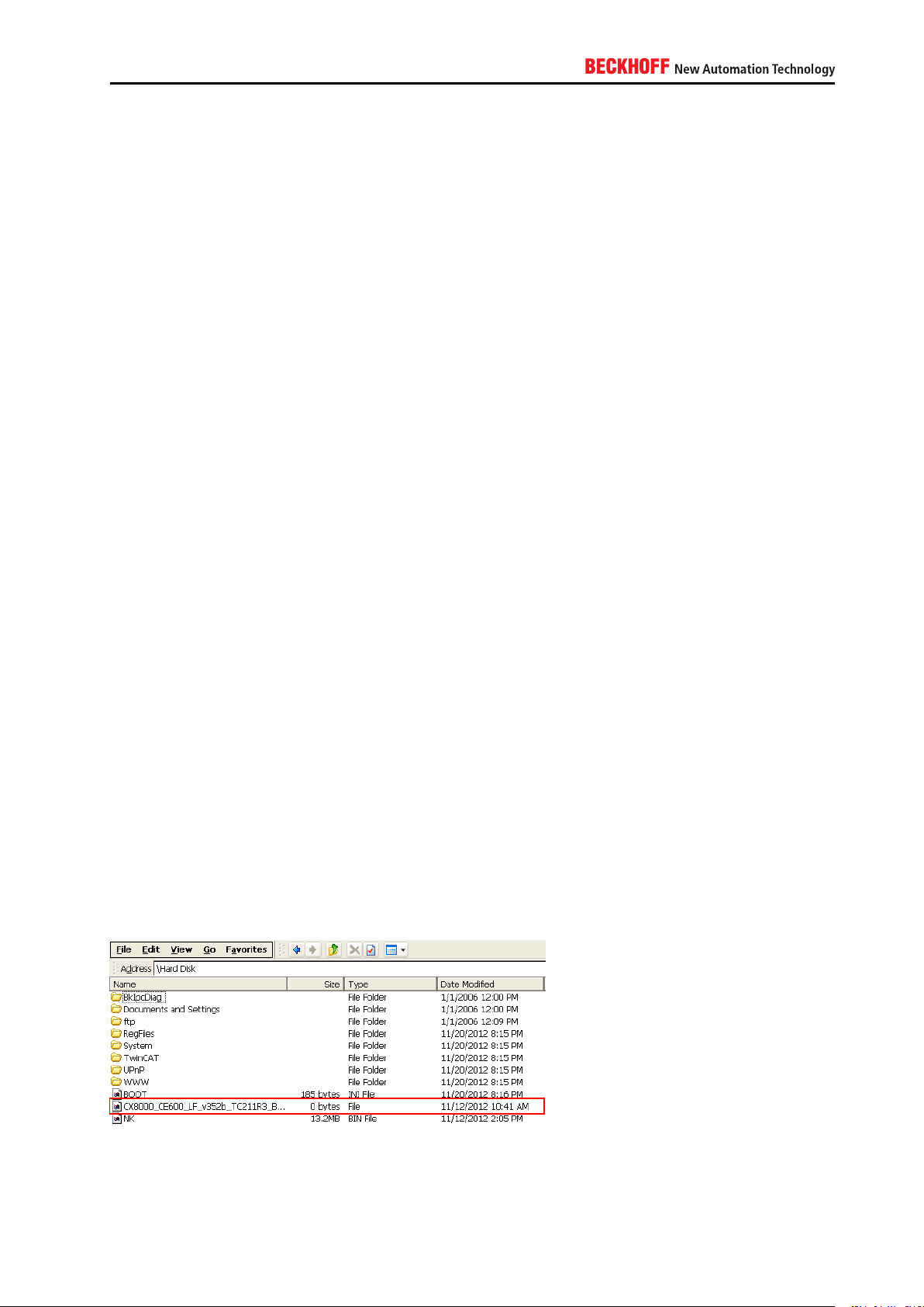
To apply updates on an Embedded-PC or Industrial-PC running Windows CE, Beckhoff periodically releases
new images and publishes them on its public FTP Server. Please check ftp.beckhoff.com/software/
embpc-control/ to see if there is a new Windows CE image available for your Embedded- or Industrial-PC.
To determine the installed version simply browse to the folder \Hard Disk\. This folder contains a file that is
named after the currently installed image version.
The Beckhoff Information System provides an article about the update procedure. See [3] for more information.
IPC Security 21
Page 22
4.2.2. Windows XP / Windows 7
4.2.2.1. Windows Updates
It is important to understand the different update scenarios from an IT infrastructure point-of-view. Depending
on the size of your IT infrastructure, one of the following scenarios could exist in your network environment.
Please note that there may be variations or even combinations of these scenarios.
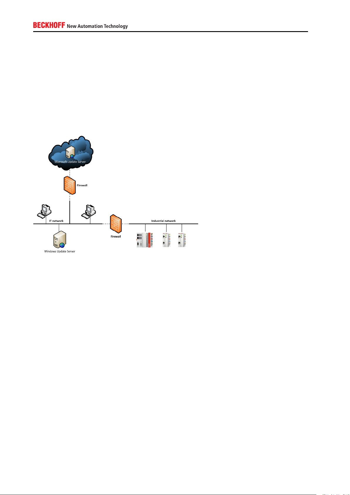
Scenario 1: Industrial network separated from IT network with no access to the Internet
This scenario is probably one of the most commonly used setups in an industrial environment. Both, the
IT network and the industrial network, are separated by a firewall. The industrial network is not allowed to
access the IT network or the Internet and therefore cannot access any external Microsoft Update Servers.
However, there may be own Update Servers located in the IT network to distribute Windows Updates which
have been approved by the company’s IT department. For more information about these update servers,
please view the Microsoft documentation about WSUS.
22
Page 23

Scenario 2: Industrial network entirely separated from IT network
In this scenario the IT and industrial network are physically separated and there is no connectivity between
both networks. Industrial controllers have no way to receive updates from a Windows Update Server, therefore all updates need to be applied manually.
Applying updates to an industrial controller
Engineering computers can and should be kept up-to-date with security updates. However, this procedure
may be more difficult in an industrial environment, depending on the IT infrastructure, as shown above.
Industrial controllers should be protected by a Write Filter (cf. chapter 3.2.3.15), which automatically leads
to another obstacle because as soon as you reboot the machine, all Windows Updates that have been
installed previously, will be reverted. Therefore, a typical workflow for maintenance would then look as
follows:
IPC Security 23
Page 24

TwinCAT – Windows Updates compatibility
We often get the question if TwinCAT has any known issues with Windows Updates. Up to this date there
have not been any known issues yet, however we cannot guarantee that for all patches in the future. Beckhoff provides customers with new operating system images every year. These images automatically include
all Windows Updates that have been released by Microsoft up to the date of image creation. These images
are tested by Beckhoff and should be installed on the corresponding industrial controller if there is the need
for an up-to-date system.
24
Page 25

4.3. Complementary Hardware mechanisms
4.3.1. Hardware appliances for Anti-Virus
Vendors of Anti-Virus software sometimes offer special hardware appliances that can be used to detect
malware as it is transmitted via the network. Please note that these systems may be useful to detect malware
as it “comes through the network” but does not protect against malware that is distributed for example via
mass storage devices like USB or floppy disk.
4.4. Complementary Software mechanisms
4.4.1. Anti-Virus software
Anti-Virus software is used to prevent, detect and remove malware, such as computer viruses, adware,
backdoors, hijackers, keyloggers, etc. Beckhoff does not give any recommendations for specific Anti-Virus
software but you can use Anti-Virus software together with TwinCAT. Just make sure to exclude the TwinCAT
directory from any background scanning.
Please see chapter A.4.3.13 for a Step-by-Step guide to configure these exclusions in some well-known
Anti-Virus software applications.
IPC Security 25
Page 26

5. Remote Access
5.1. Overview
This chapter is based on the scenario that a cyber criminal tries to attack the industrial controller from a
remote location, e.g. via the local network. Network connectivity provides a cyber criminal with more ways
to compromise system security. Industrial controllers are getting more and more connected to systems that
reside in other connectivity layers, e.g. visualizations, MES systems or even the Cloud.
5.1.1. Devices
The following table provides an overview about devices that play an important part in this scenario.
Device Category Description
IPC/EPC Industrial Controller Beckhoff Industrial-/Embedded-
PC
Switch Networking hardware Connects devices to the network
Router Networking hardware Connects different networks
with each other
Firewall Networking hardware Protects networks
Modem Networking hardware Used for incoming/outgoing di-
alup connections
5.1.2. Software components
The following table provides an overview about software packages that play an important part in this scenario.
26
Page 27

Software Category Description
Microsoft Windows XP System software Operating System
Microsoft Windows 7 System software Operating System
Microsoft Windows Embedded System software Operating System
Microsoft Windows CE System software Operating system
Windows Update client Update software Used to receive Windows Up-
dates from a central Windows
Update Server
Windows Update server Update software Used to distribute Windows Up-
dates from a central location to
network clients
Internet Information Service Webserver software Default HTTP and FTP server
in Microsoft Windows operating
systems
Remote Desktop Maintenance software Default remote maintenance
software distributed in Microsoft
Windows operating systems
(not Windows CE)
CerHost Maintenance software Default remote maintenance
software distributed in Windows
CE
5.1.3. Potential threat scenarios
The following chapter gives a short overview about possible threat scenarios, which may or may not be representative in your environment. Please take the following chapters as a means to gain a better awareness
for this scenario.
5.1.3.1. Manipulated websites
By directing a user to access a manipulated and untrusted website, an attacker could either fool the user to
disclose sensitive information, e.g. passwords, or use a vulerability of the web browser to remotely access
the operating system.
Due to this, an attacker could gain access to the system with the same privileges asthe user.
5.1.3.2. Man-in-the middle attacks
By intercepting network communiations using a non-secure network protocol, an attacker could expose
himself as a trusted source for all participants and as such manipulate or read all transferred information.
5.1.3.3. Open network ports
By scanning the network for open network ports, an attacker could use network services that have been
unnecessarily activated because they have no use in the specific system.
Due to this, an attacker may use those services to trigger unwanted events.
IPC Security 27
Page 28

5.1.3.4. Exploiting vulnerabilities of the operating system
By reaching a vulnerable network service of the operating system (e.g. SMBas described in MS11-043), an
attacker could misuse the target service.
The impact depends on the specific vulnerability, reaching from denial-of-service up to arbitrary remote code
execution with system privileges.
5.1.4. Protocols
The following table provides an overview about network protocols that play an important part in this scenario.
Each protocol will be classified according to its representation in the OSI model (Open Systems Interconnection model, see ISO/IEC 7498-1 for more information). Please note that some protocols may not fully fit
into this model, these are marked with an asterisk *.
Protocol OSI layer Description
TCP 4 Network protocol that provides a reliable, ordered, error-checked delivery
of a data stream between network programs
UDP 4 Network protocol that has been optimized for performance and throughput
and therefore does not provide ordering or reliability
RDP 4-7 Proprietary network protocol designed by Microsoft to control desktop envi-
ronments of a remote computer
ADS* 4-7 Proprietary network protocol designed by Beckhoff for internal TwinCAT
communication
OPC-UA* 7 Standardized communication protocol that provides reliable, secure and
cross-platform communication
PPTP 5 Protocol to implement virtual private networks. Internally uses TCP and
GRE
GRE* 3 Tunneling protocol used for encapsulating network layer protocols
IPSec 3 Protocol suite that provides security for IP-based communications
5.1.4.1. Network ports
You should use a firewall (see chapter refsec:firewalls) to block all network ports except the ones that are
needed in your environment.
Please see chapter A.4.1.4 for a tabular overview about all network services that are either part of a default
operating system image or can be installed later via TwinCAT Function/Supplement products.
5.1.4.2. Firewalls
Windows provides a software firewall that is part of every Windows installation. You can use this firewall to
block or allow access to specific network ports, as mentioned in chapter 5.1.4.1. When creating a firewall
rule to allow access to a specific network port, this rule should be configured in a restrictive way. You should
limit access to the network port only to the computers that need to access the port. Do not just allow access
to the network port for ALL computers. Instead, specify a single computer or a subnet range so that only
the required computers can access the network port.
Please see chapters A.4.2.7 and A.4.3.19 for more information about the firewalls that are integrated into
Microsoft Windows.
28
Page 29

5.2. Hardening
This chapter explains some common strategies that can be deployed to actively secure components that
are part of the scenario. Because the operating system architecture of Windows CE differs from Windows
XP, Windows 7 or Windows Embedded, each operating system family is represented by an own chapter.
5.2.1. Windows CE
5.2.1.1. Remote dial in
On a Windows CE device, you can configure a remote dial in connection either via an attached modem
(using the COM-Port) or via a network connection (using VPN). The following chapter gives an overview
about the general settings of the Windows CE RAS Server, before moving on to the necessary configuration
settings for each setup (modem or VPN).
Each Beckhoff Windows CE device is being deployed with a build-in RAS Server. This background service
manages all incoming dial in connections, which arrive either via an attached modem or via the network
(VPN). The following picture shows a typical example for this setup.
The Windows CE RAS Server supports two main scenarios: You can either use an attached modem to
configure an incoming dialin connection via a telephone line or you can use the corporate network to dial in
via VPN. This flexibility enables you to easily establish a dialin connection to your Windows CE device and
to integrate this setup in your IT environment.
5.2.1.2. Remote maintenance
Windows CE provides the possibility to remotely connect to the device and perform maintenance tasks on
a desktop level via the tool Cerhost. Because Windows CE only provides one local user account for system
access, this user account is also used for the remote Cerhost connection.
Please consult chapter A.4.2.3 to see how to change the password for the system user. We highly recommend you to set a password immediately because otherwise remote users can access the device unauthenticated via Cerhost.
IPC Security 29
Page 30

5.2.2. Windows XP / Windows 7
5.2.2.1. Remote dial in
Windows XP and Windows 7 enable users to configure a remote dial in connection (via VPN or an attached
modem) directly to the device. This could come in handy, for example, if your current IT infrastructure does
not include enhanced mechanisms like a separate VPN hardware or servers that provide remote access
services.
Both, Windows XP and Windows 7, support two possible scenarios: Dialing in via a telephone line (and
therefore via a modem which is attached to the IPC) or via the corporate network (VPN). Both scenarios will
be covered in more detail below. Because the configuration steps are more or less the same for Windows XP
as they are for Windows 7, this documentation only covers the configuration settings for the later operating
system. In both cases the configuration takes place in the Control Panel. Please note that, when using a
VPN dial in, you may need to configure your Internet router, so that the dial in connection gets forwarded
to your IPC Controller. Please consult the documentation of your Internet router or ask your IT department
about how to do so.
5.2.2.2. Remote maintenance
The Remote Desktop Protocol enables users to establish a remote connection to the desktop of an IPC/EPC.
RDP is by default activated in every Beckhoff operating system image. This article discusses how you can
make sure that you setup RDP in a securely manner.
5.2.2.3. Remote Desktop Protocol (RDP) and Network Level Authentication (NLA)
Since Windows 7, RDP has used Network Level Authentication (NLA) to reduce the risks of denial-ofservice
attacks. Before NLA, an RDP Client was able to establish a connection to the Windows logon screen without
actually logging on to the RDP Server. However, by presenting the logon screen, the RDP Server had to
allocate resources which could be exploited by an attacker by starting multiple RDP sessions and therefore
overstressing the RDP server. Since the implementation of NLA, remote desktop clients need to authenticate
themselves to the RDP server even before they see the remote Windows logon screen. However, since NLA
is by default enabled in every Windows 7 installation, this is not the case for Windows XP. Since Service
Pack 3, users can also use NLA under Windows XP, which is discussed in [10]. Please consult chapter
A.4.3.16 to see how NLA can be configured.
30
Page 31

Remote Desktop Protocol (RDP) and communication encryption
When making a RDP connection to a Windows 7 computer, this computer creates a self-signed certificate
used for Transport Layer Security (TLS). This allows data to be encrypted between RDP client and RDP
server. However, RDP uses a self-signed certificate by default. To use own certificates for RDP, please take
a look at [9].
Select which user accounts are enabled for RDP
By default, the local Administrator account is enabled to access the Controller via RDP. This is also why you
should change the default password as soon as possible. If you don’t need RDP, you should switch it off.
You should also specify which local user accounts should be able to access a computer via RDP. If possible,
create a separate user account for RDP access and give it exclusive rights for RDP. Please consult chapter
A.4.3.17 to see how RDP can be configured.
5.2.2.4. Network encryption
IPSec enables you to secure your IP-based network communication with regard to the security principles
Authentication, Encryption and Data integrity. IPSec is being primarily used in VPN environments but can
also be used to establish a secure channel between two internal computers. IPSec is an end-to-end security scheme which operates on layer 3 of the OSI model. This is also a main advantage of IPSec over
other security mechanisms (like SSL, TLS, SSH, etc.) because due to this, applications do not need to be
specifically designed to use IPSec. To them it just seems to be a normal IP communication. The IPSec
configuration in Windows XP consists of two parts: a Server and a Client. Let’s assume that your Controller
should be configured as the IPSec Server and a desktop computer running Windows XP as the IPSec Client.
Because the configuration of IPSec can be very bulky and can contain hundreds of different scenarios and
settings, only a basic example will be given. This example secures the network communication between a
desktop computer and the PLC Controller and is illustrated in the picture below. For more information on
IPSec please consult the Microsoft Developer Network (MSDN). As a prerequisite, both devices need to be
reachable via an IP-based network.
IPC Security 31
Page 32

A. Appendix
A.1. Remote Maintenance
Remote maintenance has always been an important part of every industrial controller. In case of a problem, service employees or application programmers could remotely connect to the IPC operating system
and perform their maintenance operation. This article will cover some of the basic scenarios from an IT
infrastructure point-of-view and discusses several possibilities how to secure the communication between
service computer and the industrial controller. Please note that this documentation makes use of standard
technologies which are available in most IT infrastructures and IPC operating systems. The Remote Desktop Protocol (RDP) will be used as an example remote maintenance tool because it is available by default
on Windows 7 based operating systems.
A.1.1. Notes about the Remote Desktop Protocol (RDP)
The configuration of RDP under Windows XP or Windows 7 has already been covered in chapter 5.2.2.3
However, that chapter did not discuss RDP as seen from a security perspective when used in different
remote maintenance scenarios as described here in this document. As it may be possible to use a raw RDP
connection via the Internet, for example by just creating a port forwarding to the default RDP port 3389/tcp
in your router, it is strongly recommended that you always use a secure channel for RDP communications,
for example by establishing a VPN/IPSec connection to the desired target first.
Please also make sure that you use an RDP version that supports Network Level Authentication (NLA) to
reduce the risk of Denial-of-Service attacks because of a high amount of concurrent RDP sessions. NLA
reduces that risk by offering an authentication prompt before the actual RDP session gets established.
Therefore, the RDP-Server (in our case: the IPC) only starts to allocate resources for the client session if
this pre-authentication was successful.
32
Page 33

Please also consult [11] for more information.
A.1.2. Remote maintenance from inside the organization
A very common scenario is that the service computer used for remote maintenance is located within the
same organization, meaning within the same corporate network. However, as the industrial network is often
separated by a Firewall from the regular IT network, the RDP communication needs to travel through that
firewall to reach the IPC.
A.1.3. Remote maintenance via central VPN server
In this scenario, the service computer used for maintenance is located outside the IT infrastructure, e.g. in
a home office. It is assumed that the IT infrastructure already provides some kind of VPN-Server. In the
picture from above, this VPN-Server is integrated into the first firewall (for example: Cisco ASA Firewall).
The communication from service computer to IPC will therefore only be encrypted until this VPN endpoint.
From that point on, the communication traveling through the IT network is plain RDP.
IPC Security 33
Page 34

A.1.4. Remote maintenance via VPN server on IPC
Hostname: Device1
IP: 192.168.1.1
ADS-NetID: 192.168.1.1.1.1
Hostname: Device2
IP: 192.168.1.2
ADS-NetID: 192.168.1.2.1.1
As described in chapter 5.2, Windows CE and Windows XP/7 operating systems provide all necessary
functionalities to create an own VPN-Server directly on the embedded device. Therefore, in this scenario
the VPN connection only needs to be routed through both firewalls, e.g. by configuring a port-forwarding
on these firewalls. The advantage of this setup is that the communication is encrypted during the whole
transition from service computer to IPC.
Please note that this setup could also be relevant for scenario A.1.2, e.g. to wrap the RDP communication
into a secure VPN / IPSec channel.
A.2. TwinCAT ADS
Connectivity in TwinCAT is generally based on the ADS communication protocol, which ensures a fast
transport of data between ADS devices, e.g. between TwinCAT PLC and TwinCAT I/O. ADS is a proprietary communication protocol developed by Beckhoff Automation. ADS has been developed to maximize
throughput and data flow between TwinCAT components and to enable communication via different transport protocols, e.g. to transmit ADS over a TCP or even a serial communication channel. Because of this
goal, ADS has not been designed to achieve security purposes and therefore does not include any encryption algorithms because of their negative effect on performance and throughput. However, ADS implements
user authentication when establishing an ADS route between two TwinCAT devices.
A.2.1. ADS routes
To enable connectvity between ADS devices, a one-time creation of corresponding ADS routes is required.
Each ADS device has an identifier, the so-called ADS-NetID. Each ADS application has its own port, the socalled ADS-Port. The ADS communication is independent of the transport protocol, e.g. ADS pakets could
be transmitted via a TCP channel. The internal ADS routing table then maps the corresponding transport
address to the ADS-NetID. Ín the following scenario two ADS devices should communicate with each other
via a TCP/IP network. Each device has its own IP-address and ADS-NetID.
34
Page 35

After the ADS route between both devices has been created, the routing table on Device1 will look as follows:
AMS-NetID Transport address Hostname (if applicable)
192.168.1.2.1.1 192.168.1.2 Device2
Similarily, the routing table on Device2 will look as follows:
AMS-NetID Transport address Hostname (if applicable)
192.168.1.1.1.1 192.168.1.1 Device1
A.2.2. ADS network ports
This scenario describes how a firewall needs to be configured so that ADS devices can communicate with
each other. Here, a laptop needs to communicate with an Embedded-PC that hosts the TwinCAT Runtime.
The firewall can either be a hardware firewall or a software firewall like the one that is integrated into Microsoft
Windows.
You need to configure the following rules in your firewall to allow ADS communication from the laptop to the
Embedded-PC:
Direction Port Protocol Action
Incoming 48898 TCP Allow
Incoming 48899 UDP Allow
A.2.3. ADS via gateway
ADS communication can also be routed via a gateway computer that separates two networks from each
other. In this case, the gateway computer needs to host a set of hierarchical ADS routes, which can either
be configured manually or via the TwinCAT Remote Manager (TwinCAT 2). There are a few important things
to consider when adding the ADS routes. Please see [1] for getting up-to-date information about this topic.
A.2.4. ADS via NAT
ADS communication can also be performed via NAT devices, e.g. a firewall. However, there are a few
important things to consider when adding the ADS routes. Please see [1] for getting up-to-date information
about this topic.
IPC Security 35
Page 36

A.3. Third-Party connectivity
Third-party connectivity involves the connection of other systems, e.g. HMI, MES, ERP or other external
applications, to the PLC runtime, e.g. to cyclically read or write process values
There are several communication protocols available to achieve this kind of connection. This article describes three common ways to communicate with TwinCAT via well-known communication protocols. For
each protocol, the implemented security mechanisms will be briefly described.
A.3.1. ADS
The Automated Device Specification (ADS) is a proprietary communication protocol developed by Beckhoff
Automation. ADS has been developed to maximize throughput and data flow between TwinCAT components
and to enable communication via different transport protocols, e.g. to transmit ADS over a TCP or even
a serial communication channel. Because of this goal, ADS has not been designed to achieve security
purposes and therefore does not include any cryptographic algorithms because of their negative effect on
performance and throughput. However, ADS implements user authentication when establishing an ADS
route between two TwinCAT devices. Please also see chapter A.3 for more detailed information about ADS
and its corresponding routes.
A.3.2. ADS-WCF
The Windows Communication Foundation (WCF) represents Microsoft’s modern web service technology.
WCF provides a single API for cross-process/cross-network communication needs in Microsoft .NET. From
a security perspective, WCF already includes security mechanisms which are available in the API via socalled profiles.
Beckhoff provides customers with a WCF web service that can be used to communicate with TwinCAT PLC.
All needed binaries for this web service are already included in TwinCAT setup and only need to be activated
and used by the customer’s application. This application would then act as an WCF-client. Please also see
[2] for more information.
A.3.2.1. Authentication
WCF supports the following models to authenticate a WCF-client:
▪ Username / password
36
Page 37

▪ Integrated Windows Authentication
▪ Authentication via a Security Token, for example Windows Azure ACS
▪ X.509 certificates
A.3.2.2. Confidentiality
WCF supports two different encryption mechanisms: Transport Security and Message Security. Transport
security applies security on a point-to-point basis, which means that, for example in an SOA architecture,
security can only be guaranteed until the first hop. Instead, Message Security applies security on a message
level, which means that the actual payload of the message is encrypted. This automatically implies security
on an end-to-end basis, also if the message is being routed through several intermediates.
A.3.3. OPC-UA
OPC Unified Architecture (OPC-UA) is the new technology generation of the OPC Foundation for the secure,
reliable and manufacturer-neutral transport of raw data and pre-processed information from the manufacturing level into the production planning or ERP system. With OPC-UA, all desired information is available
to every authorized application and every authorized person at any time and in any place.
A.3.3.1. Authentication
Upon connection establishment, the user identifies himself via:
▪ X.509 certificates
▪ Username / password
▪ or Kerberos
IPC Security 37
Page 38

A.3.3.2. Integrity
The signing of messages prevents a third party from changing the contents of a message. This prevents,
for example, a write statement to open a switch being falsified by a third party and the switch being closed
instead.
A.3.3.3. Confidentiality
The confidentiality of the exchanged information is secured by the encryption of the exchanged messages.
For this, modern cryptographic algorithms are used. Different security levels can be selected according to
the requirements of the respective application. In some areas, it may be sufficient to sign the messages in
order to prevent changes being made by third parties, while additional message encryption is necessary in
other areas where the data must also not be read by third parties.
A.3.3.4. Authentication and authorization of applications
Each OPC-UA application identifies itself via so-called software and application instance certificates. With
the aid of software certificates it is possible to grant certain client applications extended access to the information on an OPC-UA Server. Application instance certificates can be used to ensure that an OPC-UA
Server communicates only with preconfigured clients. On the other hand, a client can ensure by means of
the server’s application instance certificate that it is really speaking to the correct server (similar to the SSL
certificates of a website/webserver).
By implementing this protocol in the TwinCAT product “TwinCAT OPC-UA Server”, Beckhoff Automation
enables customers to use this modern technology to establish a secure connection via a standardized communication protocol between a third party product and TwinCAT PLC.
A.3.4. Modbus
The original Modbus protocol is a serial communications protocol that has been developed in the late 1970s.
The main goals were to provide a communication protocol that had industrial applications in mind, is easy
to deploy and maintain, and moves raw bits or words without implementing an information model. This simplicity made it very popular during the last 30 years. However, this simplicity also makes it more challenging
to use Modbus in modern industrial systems because today we have other, more complex requirements to
a communication protocol than 30 years ago, e.g. the need for security and information models to transfer
complex data and metadata. The original Modbus protocol does not implement security mechanisms, e.g.
it is not possible to encrypt data communications or use client/server authentication.
Although Beckhoff also provides two TwinCAT Functions for Modbus RTU and Modbus TCP, we recommend
customers to use more modern communication protocols that already implement security mechanisms, e.g.
OPC-UA.
A.4. Step-by-Step
The following chapter provides step-by-step explanations of all previously addressed topics. Please note
that some menu items or controls may have other names, depending on the operating system that is used.
38
Page 39

A.4.1. General information
A.4.1.1. Overview Beckhoff web-based services
The following table gives an overview about all Beckhoff web-based services that are included by default
in operating system images deployed by Beckhoff. These services are hosted by the Internet Information
Service (IIS) by the corresponding operating system.
Name Description OS
IPC-Diagnostics Website that displays Hard- and
Software information about the
IPC or EPC.
TcOpcXmlDa Provides an OPC-XML-DA end-
point to get data access to PLC
symbols.
* WinXP = Windows XP Pro, Windows 7 Pro, Windows Embedded
A.4.1.2. Complex passwords
Strong passwords are an important protection that helps to configure safe environments. The following
requirements define a strong password and are adapted from a Microsoft article about strong passwords:
▪ Password length: Make sure that the password consists of at least 8 characters
▪ Password complexity: Include letters, punctuations, symbols and numbers
▪ Password variation: Change the password often
▪ Password variety: Do not use the same password for everything
WinCE, WinXP*
WinCE
There are many ways to create a strong password. The following table shows some suggestions that might
help you to remember a password easily:
What to do Example
Start with a sentence or two Complex passwords are safer
Remove the spaces between the words Complexpasswordsaresafer
Turn words into shorthand or intensionally misspell a
word
Add length with numbers and symbols ComplekspasswordsRsafer#2013#
Keep in mind: Cyber criminals use sophisticated tools that can rapidly decipher passwords. Avoid creating
passwords that use:
▪ Dictionary words in any language
▪ Words spelled backwards, common misspellings and abbreviations
▪ Sequences or repeated characters, e.g. 12345678 or abcdefgh
▪ Personal information, e.g. birthday or passport number
ComplekspasswordsRsafer
IPC Security 39
Page 40

A.4.1.3. Overview Beckhoff software paths
The following table gives an overview about all Beckhoff software applications that may be executed in a
Windows user context. They are not required to run TwinCAT but usefull for diagnostics (e.g. Scope-View).
Other applications, like IPC-Diagnostics or TwinCAT System Service, are not affected by software restriction
policies because they run as a Windows Service under the Local System context.
TwinCAT 3 System
Application Path
TwinCAT XAE %PF%\Microsoft Visual Studio 10.0\Com-
mon7\IDE\devenv.exe
Beckhoff FBWF Manager %PF%\FBWFMgr\Beckhoff FBWF Manager.exe
TwinCAT ADS Test Tool %TC%\Common32\TcAdsTest.exe
TwinCAT Scope 2 View %TC%\Functions\TE130X-TC3-Scope-
View\TwinCatScopeView2.exe
TwinCAT Event Bar %TC3DIR%\Components\TcEventLogger\TcEventBar.exe
TwinCAT SysUI %TC3DIR%\System\TcSysUI.exe
TwinCAT AMS Remote Manager %TC%\ADS Api\TcAdsDll\TcAmsRemoteMgr.exe
Beckhoff EWF Manager %PF%\BEWFMgr\BEWFMgr.exe
TcSwitchRuntime %TC%\TcSwitchRuntime\TcSwitchRuntime.exe
TwinCAT 3 Functions
Application Path
TF6100 Configurator %TCFUN%\TF6100-OPC-
UA\Win32\Configurator\TcOpcUaConfigurator.exe
TF6100 Sample Client %TCFUN%\TF6100-OPC-
UA\Win32\SampleClient\UaSampleClient.exe
TF6120 Configurator %TCFUN%\TF6120-OPC-
DA\Win32\Configurator\TcOpcCfg.exe
TF6120 Client %TCFUN%\TF6120-OPC-DA\Win32
\SampleClient\TcOpcClient.exe
TF6250 Configurator %TCFUN%\TF6250-Modbus-
TCP\Win32\Server\TcModbusCfg.exe
TF6420 Configurator %TCFUN%\TF6420-DatabaseServer\Win32\
Configurator\TcDatabaseSrv_Configfileeditor.exe
Abbreviations:
▪ %TC%: TwinCAT directory, e.g. C:\TwinCAT
▪ %TC3DIR%: TwinCAT 3 directory, e.g. C:\TwinCAT\3.x
▪ %TCFUN%: TwinCAT Function directory, e.g. C:\TwinCAT\Functions
▪ %PF%: Program Files directory, e.g. C:\Program Files
Please note: In order for the TwinCAT startmenu entries to work properly, you also need to add them to the
Whitelist if needed.
40
Page 41

A.4.1.4. Overview Beckhoff network services
Default network services
The following table provides an overview about network services that are part of a default operating system
image that has been deployed by Beckhoff.
Network service Network ports: Description
CerHost 987 / tcp (incoming) Software tool to control a Windows CE device re-
motely.
FTP-Server 21 / tcp (incoming) Network service that provides FTP (File Transfer Pro-
tocol) access to the industrial controller.
IPCDiagnostics
Remote Desktop
SMB 137 / tcp, udp (incoming)
TwinCAT ADS 48898 / tcp (incoming, outgoing)
4852 / tcp (incoming)
80 / tcp (incoming)
5120 / tcp (incoming)
3389 / tcp (incoming) Software tool to control a Windows XP or Windows 7
138 / tcp, udp (incoming)
139 / tcp, udp (incoming)
445 / tcp (incoming)
48899 / udp (incoming, outgoing)
Service that provides access to hard-/software infor-
mation of the industrial controller.
device remotely.
SMB is used for file and printer shares. The actually
used ports depend on the operating system.
Communication ports for the TwinCAT ADS protocol.
Other network services
The following table provides an overview about network services that can be acquired from Beckhoff, e.g.
TwinCAT Supplement products.
Service / product Network ports:
TF6100 OPC-UA configurable, but by default 4840/tcp (incoming)
TF6120 OPC-DA dynamic (related to DCOM) between 1024 and 65535 (incoming)
TF6250 Modbus TCP 502/tcp (incoming)
TF6310 TCP-IP configurable (incoming/outgoing)
TF6300 FTP 20/tcp (outgoing)
21/tcp (outgoing)
please also check TF6300 documentation for more information about active/passive
FTP
TF6420 Database
Server
depends on the database, please check TF6420 documentation for more information.
Always outgoing connections.
A.4.2. Windows CE
A.4.2.1. Setting a device password
To configure a device password on Windows CE, please perform the following steps on the CE device:
1. Select Start → Control Panel → Password
IPC Security 41
Page 42

2. Enter a password in the filed Password and Confirm password
3. Finish with OK
After a reboot, users will not be able to select a dialog or start an application without entering the password.
Please also compare to chapter 3.2.2.1.
A.4.2.2. Deactivate webserver
To deactivate the Windows CE webserver, simply modify the following Registry Key on the Windows CE
device:
HKEY_LOCAL_MACHINE\Services\HTTPD\Flags
By setting this DWORD value to “4”, the Webserver gets deactivated completely. Please keep in mind that
all services which depend on the Webserver will not work afterwards!
A.4.2.3. Changing password for system user
Please perform the following steps to change the password for the System user:
1. Open the Start Menu and go to the Control Panel
2. Double-click on Password
3. Enter a password of your choice but remember to use a strong password (a minimum of 8 characters
which also includes special characters) see A.4.1.2
4. Enable the checkbox At Power On. This also enables the password for system logon.
42
Page 43

A.4.2.4. Changing password for SMB and FTP user
To change the password for an SMB or FTP user account, you can use the Beckhoff CX Configuration Tool.
To start the program, please perform the following the steps:
1. Open the Start Menu and go to the Control Panel
2. Start the program by double-clicking CX Configuration
3. Local user accounts can then be configured via the tab FTP
4. Please do not get confused: User accounts in this tab will both be used for the FTP and for the SMB
Server
5. You can configure a new user account by right-clicking a blank area in the table and selecting Add
user
6. After you’ve entered a username and a password, you can close the CX Configuration by clicking on
OK. Please make sure to restart your device for the changes to take effect
A.4.2.5. Changing password for RAS user
The Beckhoff CX Configuration Tool can also be used to configure user accounts for the integrated RAS
Server. Start the tool by performing the following steps:
1. Open the Start Menu and go to the Control Panel
2. Start the program by double-clicking CX Configuration
3. Switch to the tab RAS Control
IPC Security 43
Page 44

4. The RAS User Management can then be found on the right hand side in this window
For a detailed description of the RAS Server, please consult the corresponding chapter here in this documentation.
A.4.2.6. Configuring RAS
You can configure the RAS Server via the CX Configuration tool in the Control Panel on your CE device:
1. Open the Start Menu and go to the Control Panel
2. Start the configuration program by double-clicking CX Configuration
3. Navigate to the tab RAS Control
The Windows CE RAS Server is disabled by default. To enable it, simply perform the following steps in the
Beckhoff CX Configuration Tool:
1. Click on the checkbox Enable RAS Server
2. Select one or more connection channels (lines) and click on Enable Line. These channels configure
whether you want to use an attached mode for the dial in or the network (VPN). Both settings will be
described in more detail below
3. Add a user account which may dial in via one of the lines. Please note that this user account is not to
be mixed with user accounts used for accessing a SMB share!!
4. Optionally, select another IP-Address setting. Each setting changes how clients will receive an IP
address. The available options for IP addressing are: DHCP, AutoIP (default), Static
When finished, click on OK and restart your system. You should always use this graphical tool to setup
the RAS Server. However, if you want to further customize your RAS setup, you can make more detailed
settings by modifying the Windows CE registry:
1. Open the Start Menu and click on Run…
2. Enter regedit and click on OK. The Registry Editor opens
3. Navigate to HKEY_LOCAL_MACHINE\Comm\ppp\Server\Parms. Here you can set further parameters for the RAS Server. Please note that the key ppp only exists after the RAS Server has been
enabled!
The following table shows the different attributes in this registry key:
44
Page 45

Attribute Type Default value Description
Enable DWORD 0x00000000 Disables (0) or enables (1) RAS Server
StartupDelaySeconds DWORD 0x00000000 Specifies the wait time after boot, before the RAS Server is
being started.
UseDHCPAddresses DWORD 0x00000000 Disables (0) or enables (1) the use of DHCP addresses for
clients. Should be used if the CE device contains an internal
DHCP Server software.
UseAutoIpAddresses DWORD 0x00000000 See explaination above
AutoIpSubnet DWORD 0xC0A80000 Subnet IP for AutoIp configuration. The hexadecimal value
is determined according to the calculations below.
AutoIpSubnetMask DWORD 0xFFFF0000 Subnet Mask for AutoIp configuration. The hexadecimal
value is determined according to the calculations below.
StaticIpAddrStart DWORD 0xC0A8FE01 First IP Address for Static configuration. The hexadecimal
value is determined according to the calculations below.
StaticIpAddrCount DWORD 0x000000FE Amount of IP Addresses for static configuration.
AuthenticationMethods DWORD 0x00400000 Discussed in more detail below
Flags DWORD 0x00000000 Discussed in more detail below
The value of each IP address related attribute is determined according to the binary and hexadecimal representation of the address. An IP address consists of 4 values, each value equals 1 byte or rather 8 bits.
Therefore the hexadecimal value of this IP address can be derived directly from the binary representation
by converting every 4 bits to hex, for example:
IP address 192.168.0.1
Binary 11000000.10101000.00000000.00000001
Hexadecimal C0.A8.00.01 à0xC0A80001
The following table shows some examples for common IP subnets addresses.
Subnet IP Subnet Mask Value IP (Hex) Value Mask (Hex)
192.168.0.0 255.255.255.0 0xC0A80000 0xFFFFFF00
192.168.1.0 255.255.255.0 0xC0A80100 0xFFFFFF00
192.168.2.0 255.255.255.0 0xC0A80200 0xFFFFFF00
172.16.0.0 255.255.0.0 0xAC100000 0xFFFF0000
The attribute AuthenticationMethods configures the RAS Server for the usage of different protocols for client
authentication. Please note that this value configures protocols which should be prohibited by the Server!
That means, if a client tries to establish a RAS connection with an authentication protocol which is prohibited
by the server, the connection fails.
IPC Security 45
Page 46

Protocol Value (Hex) Information
PAP 0x00040000 Password for authentication is being transmitted in clear-text! In-
secure!
CHAP 0x00080000 Uses a random value, together with the password, for creating a
one-way hash value which is being transmitted to the server for
authentication.
MS-CHAP 0x00100000 This is Microsoft’s implementation of CHAP. It provides several
enhancements to standard CHAP.
MS-CHAP v2 0x00200000 This is version 2 of the MS-Chap protocol. It provides mutual
authentication between peers. This protocol should be used!
EAP 0x00400000 Developed by the IETF. Supports several authentication mech-
anisms like RADIUS, certificates, … . However, this usually implies other software packages to be installed on the CE device
and is therefore disabled by default.
To prohibit more than one protocol, you need to interpret the hexadecimal value like a bitmask and add the
bit-wise values. For example:
Protocols to prohibit PAP, CHAP, MS-CHAP
PAP value binary 0000 0000 0000 0100 0000 0000 0000 0000
CHAP value binary 0000 0000 0000 1000 0000 0000 0000 0000
MS-CHAP value binary 0000 0000 0001 0000 0000 0000 0000 0000
Overall binary value (sum) 0000 0000 0001 1100 0000 0000 0000 0000
Hex value to configure 0x001C0000
The Flags attribute configures if the RAS Server should allow any of the following features. Any of these
features can be combined by setting the appropriate bitmask value (similar to the procedure from above).
Feature Value
(Hex)
Data Encryption 0x01 Requires data encryption, if set
Unauthenticated Access 0x02 Allows unauthenticated access, if set
Use of VJ header compression 0x04 Prevents the use, if set
Use data compression 0x08 Prevents the use, if set
Configure a modem connection
You can use a to the CE device attached modem for enabling incoming dial in connections. Therefore, the
resulting connection is a point-to-point communication via the telephone network.
Information
46
Page 47

To configure the RAS Server for incoming modem connections, you need to open the CX Configuration tool
on your CE device:
1. Open the Start Menu and go to the Control Panel
2. Start the configuration program by double-clicking CX Configuration
3. Navigate to the tab RAS Control
4. Select a modem line and click on Enable Line, for example Hayes Compatible...
5. Please makesure that you also made all other necessary settings, like configuring a user account
or IP-Address settings. Those settings are described at the beginning of this document (General
information...)
6. Please restart your device
Every Windows version comes with an integrated dial in Client which supports the establishment of an
outgoing modem connection. In case of Windows 7, you can configure a modem connection to your CE
device as follows:
1. Open the Start Menu and go to the Control Panel
2. Open Network and Internet, then go to Network and Sharing Center
3. Click on Set up a new connection or network
IPC Security 47
Page 48

4. Select Connect to a workplace
5. Select No, create a new connection (Please note: This screen only shows if there are any dial in
connections configured on your system)
6. Select Dial directly
7. Select the modem you would like to use and click on Next
8. Enter a telephone number and click on Next
9. Enter a Username and a Password for this connection. This is the username you configured in the
RAS Server settings on your CE device
10. Finally, click on Connect to save this profile and establish a connection to your CE device
Configure a VPN connection
VPN is the abbreviation for Virtual Private Network. In Windows CE, VPN is part of the RAS Server and
enables you to use an existing network connection to dial in into your PLC controller via a secure channel.
As a result, you can get an IP-based connection to your CE device. The CE RAS Server uses by default the
PPTP protocol (Point-to-Point Tunneling Protocol) for incoming VPN connections. To enable the connection
establishment from outside your corporate network you therefore need to open the ports specific for PPTP
on your firewall, which are TCP 1723 for the initialization and GRE for data control. These ports need to be
forwarded to your CE device (Port Forwarding)! Please consult the documentation of your router/firewall to
see how this can be done in your specific case.
48
Page 49

To configure the RAS Server for incoming VPN connections, you need to open the CX Configuration tool on
your CE device:
1. Open the Start Menu and go to the Control Panel
2. Start the configuration program by double-clicking CX Configuration
3. Navigate to the tab RAS Control
4. Select one or more VPN lines and click on Enable Line. The amount of lines equals the number of
concurrent VPN connections.
5. Please make sure that you also made all other necessary settings, like configuring a user account
or IP-Address settings. Those settings are described at the beginning of this document (General
information...)
6. Please restart your device
Since Windows XP, every Windows version comes with an integrated VPN Client which also supports the
PPTP protocol. In case of Windows 7, you can configure a VPN connection to your CE device as follows:
1. Open the Start Menu and go to the Control Panel
2. Open Network and Internet, then go to Network and Sharing Center
3. Click on Set up a new connection or network
4. Select Connect to a workplace
5. Select No, create a new connection (Please note: This screen only shows if there are any dialin
connections configured on your system)
6. Select Use my Internet connection (VPN)
7. Enter the Internet address of the CE device. Please note: If you want to use this VPN connection from
outside your corporate network, you need to enter the IP-Address of your router/firewall where you did
the port forwarding settings as mentioned above.
8. Click on Next
9. Enter a Username and a Password for this connection. This is the username you configured in the
RAS Server settings on your CE device
10. Finally, click on Connect to save this profile and establish a connection to your CE device
IPC Security 49
Page 50

A.4.2.7. Configuring the firewall
The firewall for Windows CE can be configured via the Beckhoff CX Configuration Tool.
A.4.3. Windows XP / Windows 7
A.4.3.1. Changing user passwords
To manage local Windows user accounts on your Windows XP or Windows 7 based device, simply perform
the following steps to open the User Management Console
1. Open the start menu and then browse to the Control Panel
2. Open Administrative Tools and double-click on Computer Management
3. Expand the entry System Tools
50
Page 51

A.4.3.2. Creating an Audit Policy
To create an Audit Policy, please perform the following steps:
1. Open the Local Security Settings by opening the Control Panel and starting Administrative Tools
2. Expand Local Policies and select Audit Policy
3. Activate the setting Audit object access and restart your system
Now that you have enabled auditing on a file-and-folder level you need to specify which file or folder should
be audited:
1. Right-click the corresponding file or folder and select Properties
2. Open the Security tab and click on Advanced
3. Open the Auditing tab and click on Add
4. Add a user account or user group which you want to audit, for example Administrator
5. Select one or more audit events, for example Full Control and click on OK
6. Close all open windows
Every time the chosen user account (In our example the Administrator account) accesses the file or folder
with the selected audit event (In our example Full Control), an entry with the category Object access will be
created in the Windows Eventlog:
1. Open the Control Panel and start the Administrative Tools
2. Start the Event Viewer and select Security
Please always keep in mind that the size of the Eventlog may and should be configured according to the
free space on your hard disk.
A.4.3.3. Configuring password policies
To configure a password policy, please perform the following steps:
1. Open the Control Panel and start Administrative Tools, then Local Security Settings
2. Expand Account Policies and select Password Policy
IPC Security 51
Page 52

A.4.3.4. Configuring security templates
To view the settings of each template in more detail, you can start the Security Templates Snap-in by performing the following steps:
1. Open Start and select Run
2. Enter mmc.exe and click on OK
3. Go to File, select Add/Remove Snap-in and click on Add
4. Select the Security Templates Snap-in, click on Add and then on OK
5. Expand the entries Security Templates and C:\Windows\Security\Templates
Then browse the template you wish to view. Please note: The templates which are named dc are domain
controller templates and do not apply to your PLC Controller. To apply a template, you need to open the
Security Configuration and Analysis Snap-in:
1. Open Start and select Run
2. Enter mmc.exe and click on OK
3. Go to File, select Add/Remove Snap-in and click on Add
4. Select the Security Configuration and Analysis Snap-in, click on Add and then on OK
52
Page 53

5. Right-click the Security Configuration and Analysis entry and select Open Database
6. Enter a name for this database (can be any name)
7. Select the template you wish to apply
8. Right-click the entry again and select Analyze Computer Now…
9. Enter a path to the error log file or leave the suggested path and click on OK
10. The system now compares your current security settings with the settings from the template. This
gives you the opportunity to double-check the settings before applying them to your system. Here you
can also customize the settings so that they suit your needs, for example setting a stronger password
policy
11. If you want to apply the settings, right-click the root entry again and select Configure Computer
12. Enter a path to the error log file or leave the suggested path and click on OK. Windows now applies
the security settings from the template to your system.
13. Please note that you need to restart your system afterwards.
A.4.3.5. Disabling Autorun
You can disable this feature by adding a DWORD key called NoDriveTypeAutorun to the Windows registry:
HKEY_CURRENT_USER\Software\Microsoft\Windows\CurrentVersion\Policies\Explorer
The value of this key depends on which the drives for which you would like to disable AutoRun. The following
table shows examples for these values:
IPC Security 53
Page 54

Value Description
0x1 Disables Autorun on drives of unknown type
0x4 Disables Autorun on removable devices
0x8 Disables Autorun on fixed drives
0x10 Disables Autorun on network drives
0x20 Disables Autorun on CD-ROM drives
0x40 Disables Autorun on RAM disks
0x80 See 0x1
0xFF Disables Autorun on all kinds of drives
If you would like to configure a mix of the settings shown above, you only need to add the corresponding
hexadecimal values, for example 0x4 + 0x10 = 0x14.
A.4.3.6. Deactivating the webserver
To deactivate the IIS Webserver, please open the Windows Service MMC, for example, by going to Start →
Run → services.msc and pressing Enter. Deactivate the World Wide Web Publishing Service and IIS Admin
Service.
Please keep in mind that all services that depend on the Webserver won’t work afterwards!
A.4.3.7. Deactivating the Windows registry
Blocking access to Windows Registry tools like regedit.exe or regedt32.exe can be achieved by adding the
DWORD value DisableRegistryTools to the following registry key:
HKEY_CURRENT_USER\Software\Microsoft\Windows\CurrentVersion\Policies\
Setting this value to 1 results in an error message as soon as one of the registry editors is started. Please
note that you could also block access to these tools by creating a corresponding Software Restriction Policy,
as described in chapter 3.2.3.5.
A.4.3.8. Deactivating the Windows command prompt
To block access to the Windows command line, just add the DWORD value DisableCMD to the following
registry key:
HKEY_CURRENT_USER\Software\Policies\Microsoft\Windows\System\
54
Page 55

This registry key may contain one of the following values:
Value Description
0x0 Access to the command line is allowed and batch files may be executed
0x1 Access to the command line is blocked and no batch files may be executed
0x2 Access to the command line is blocked but batch files may be executed
Please note that you may also use a Software Restriction Policy to disable an execution of cmd.exe, as
described in chapter 3.2.3.5.
A.4.3.9. Hiding the network environment
To hide the network environment from the user’s desktop, simply add the DWORD value
{F02C1A0D-BE21-4350-88B0-7367FC96EF3C} to the following registry key:
HKEY_CURRENT_USER\Software\Microsoft\Windows\CurrentVersion\Policies\NonEum\
Setting this key to 1 hides the network environment from the user’s desktop.
A.4.3.10. Disallowing users to add network drives
To hide the Map network drive feature, simply add the DWORD value NoNetConnectDisconnect to the
following registry key:
HKEY_CURRENT_USER\Software\Microsoft\Windows\CurrentVersion\Policies\Explorer\
By setting this key to 1 hides that feature from the user’s Windows Explorer.
A.4.3.11. Hiding or restricting access to drive letters
To restrict access to drive letters, you need to create a new REG_DWORD called NoViewOnDrive under
the following registry key:
HKEY_CURRENT_USER\Software\Microsoft\Windows\CurrentVersion\Policies\Explorer\
If this registry key does not exist, you need to create it manually. The value of this key depends on the drive
letters you want to restrict access to and will be calculated according to the following listing:
A 1
B 2
C 4
F 32
G 64
H 128
K 1024
L 2048
M 4096
P 32768
Q 65536
R 131072
U 1048576
V 2097152
W 4194304
Z 33554432
All 67108863
D 8
E 16
I 256
J 512
N 8192
O 16384
S 262144
T 524288
X 8388608
Y 16777216
If you decide to restrict access to the drive letters A, B, D and P the value of the key would be 1+2+8+32768
= 32779. For a combination of A, B and H it would be 131. After you’ve entered the value you need to
IPC Security 55
Page 56

restart the operating system to make the changes become active.
To make a drive letter disappear from the Explorer view, you need to create a new REG_DWORD key called
NoDrives under the registry path from above. This key’s value needs to be calculated according to the table
above. Be aware that the drive letters are indeed not visible however they can be accessed by directly
referencing them using the command line or other file access software!
It is possible to use both settings simultaneously.
A.4.3.12. Configuring EFS
To configure the Encrypting File System (EFS), please perform the following steps:
1. Right-click a file or folder and select Properties
2. Under the tab General, click on the button Advanced, which will show you a window as follows:
3. To encrypt the selected resource, activate the checkbox Encrypt contents to secure data
If this is the first time you encrypted a file or folder on this system, Windows XP automatically adds an EFS
certificate to the local certificate store. It is important that you create a backup of this certificate, otherwise
you wouldn’t be able to recover your encrypted resources in case of a system crash! To view and export
the certificate, please do the following:
1. Open Start and select Run
2. Enter mmc.exe and click on OK
3. Go to File, select Add/Remove Snap-in and click on Add
4. Click on Add and select the Certificates Snap-in
5. Click on Add again and select My user account
6. Click on Finish and close all open windows. You should now see the following window:
56
Page 57

7. In this window, expand the folder Personal and select Certificates
8. You should now see a certificate whose Intended Purpose shows Encrypting File System:
This is the certificate which will be used by Windows for signing and encrypting files or folders. To make a
backup of this certificate right-click it and select All Tasks → Export. This will start a wizard which will guide
you with the export procedure.
1. Select
2. Select Personal Information Exchange, Include all certificates… and Enable strong protection…
3. Enter a password of your choice. This password will be needed to import the certificate in case of a
system crash so keep it secret!
4. Enter a path where the backup should be stored
After the wizard finishes, a PFX-file will be generated under the specified path. Please save this file to an
external and persistent location! In case your system crashes, this file ensures that you will still be able to
recover your encrypted files and folders!
Attention: Please make sure to not encrypt your whole system drive, Windows system files or the TwinCAT
folder because this could result in severe issues to your system and could cause your PLC application to
not run properly anymore!
A.4.3.13. Configuring Anti-Virus exclusions
This section shows how to exclude the TwinCAT directory in some prominent Anti-Virus programs.
Export Private Key
Norton AntiVirus
The following screenshots are based on Norton AntiVirus 2012. In order to exclude the TwinCAT directory:
1. Open the Norton AntiVirus user interface
IPC Security 57
Page 58

2. Click on Settings and select the tab Computer
3. Click on Configure items to exclude from Scans
4. Click on Add and select the TwinCAT installation directory, by default C:\TwinCAT\, followed by clicking
on OK
5. You will now see the TwinCAT directory listed in the exclusion list
58
Page 59

Trend Micro
The following screenshots are based on Trend Micro Titanium AntiVirus Plus 2012.
1. Open the settings by clicking on the gear icon
2. On the left side of the window, click on Exception Lists
3. Click on Add
IPC Security 59
Page 60

4. Click on Browse and select the TwinCAT installation directory, by default C:\TwinCAT\, followed by
clicking on Open
5. Activate the checkbox next to the TwinCAT directory
6. Click on OK to close the settings window
A.4.3.14. Restricting USB drives
To prevent users from attaching USB Storage devices, for example a USB memory stick, to the IPC, you
only need to deny both the local user account and the SYSTEM account access to the following files, where
%SystemRoot% defines the location of the Windows directory:
▪ %SystemRoot\%\Inf\Usbstor.pnf
▪ %SystemRoot%\Inf\Usbstor.inf
▪ %SystemRoot%\System32\DriverStore\Usbstor.inf*
This prevents users to add new USB Storage devices to the system. However, if there have been some
previously plugged-in USB devices you need to disable the USB Storage driver completely by changing
the ImagePath value under HKEY_LOCAL_MACHINE\SYSTEM\CurrentControlSet\Services\UsbStor to a
value of your choice, for example just add the String .deactivated.
60
Page 61

On the other hand, if you only want specific USB Storage devices to be available on the Controller, the above
steps can easily be adapted to your needs. Plug in all USB Storage devices which should be accessible
on the Controller and then deny access to the files, as mentioned above. Of course, you can also disable
USB devices in the system’s BIOS but this would also include non-Storage devices! Please keep in mind,
that some USB devices are necessary for your Controller to run properly, for example a Control Panel (CP)
which uses the USB port for its touchscreen!
A.4.3.15. Configuring RAS
The following chapters explain how to configure the RAS service.
Configuring a VPN dial in
1. Open the Control Panel and then the Network and Sharing Center
2. Click on Change adapter settings
IPC Security 61
Page 62

3. Open the File menu and select New incoming connection
4. To configure a new user account which may be used for the dial in connection, please click on Add
someone... and specify the user credentials (use a string password) for the new user account. Afterwards click on OK, then on Next.
62
Page 63

5. When asked How to connect?, select Through the Internet and click on Next. This is also the location
where you differentiate between a VPN and a modem dialin (see below).
6. Make sure that all needed network protocols and services are listed, then click on Allow access
IPC Security 63
Page 64

7. After the connection has been set up, you can use the Windows VPN Client to establish a connection
to the IPC Controller. Please see below for the necessary configuration steps.
Configuring a modem dial in
Configuring a modem dial in connection is very similar to configure a VPN dial in connection (see above).
Up to the step where you need to select how people will connect, the configuration is even identical. In this
dialog, however, you need to select through a dial-up modem and then select the modem attached to the
IPC device. In the next dialog, make sure that all needed network protocols and services are listed, followed
by clicking on Allow access.
Configuring the client device
Since Windows XP, every Windows version comes with an integrated RAS Client which supports either an
outgoing VPN or Modem connection. In case of Windows 7, you can configure a VPN connection to your
CE device as follows:
1. Open the Start Menu and go to the Control Panel
2. Open Network and Internet, then go to Network and Sharing Center
3. Click on Set up a new connection or network
4. Select Connect to a workplace
5. Select No, create a new connection (Please note: This screen only shows if there are any dial in
connections configured on your system)
6. Select Use my Internet connection (VPN)
7. Enter the address of the IPC. Please note: If you want to use this VPN connection from outside your
corporate network, you need to enter the IP-Address of your router/firewall where you did the port
64
Page 65

forwarding settings as mentioned in the documentation of your Internet router.
8. Click on Next
9. Enter a Username and a Password for this connection. This is the username you configured in the
RAS Server settings on your CE device
10. Finally, click on Connect to save this profile and establish a connection to your CE device
A.4.3.16. Configuring NLA
Under Windows 7, you can restrict access to RDP for NLA-only devices by doing the following:
1. Right-click the symbol My Computer and select Properties
2. Open Remote Settings
3. Select Allow connections only from computers running Remote Desktop with Network Level Authen-
tication
Please note that, even with the use of Network Level Authentication, RDP should only be used over a secure
communication channel, as described in our remote maintenance scenarios.
IPC Security 65
Page 66

A.4.3.17. Configuring RDP
You can configure which users are able to access a computer via RDP by performing the following steps:
1. Right-click the symbol My Computer and select Properties
2. Then switch to the tab Remote and deactivate the checkbox Allow users to connect remotely…
As mentioned before, the local Administrator account has access to this feature by default. If you also want
other user accounts to have access to RDP, you can select those user accounts by clicking on the button
Select Remote Users…. The shown list represents group membership of the local group Remote Desktop
Users. Therefore, you can optionally check group membership by going to the User Management:
1. Right-click the symbol My Computer again and select Manage, which opens the Computer Manage-
ment
2. Expand the entry Local Users and Groups, then navigate to Groups
3. Open the Remote Desktop Users group by double-clicking on it
There is also a second option how you can give a user access to RDP:
1. Start the Control Panel and open the Administrative Tools
2. Start the Local Security Policy
3. Expand the entry Local Policies and navigate to User Rights Assignment
4. There you will see an entry called Allow logon through Terminal Services
5. Add user accounts and user groups to grant them access to RDP. Please note, that each additional
entry added here will not show up in the System Properties because only the group membership of
Remote Desktop Users will be shown there!
66
Page 67

A.4.3.18. Configuring IPSec
Setting up the IPSec Server (PLC Controller)
To configure the PLC Controller as an IPSec Server you need to open the IP Security Policy Snap-in:
1. Go to Start → Run and enter mmc.exe, then click on OK
2. Open File and select Add/Remove Snap-in
3. Click on Add and add the IP Security Policy Management from the Local Computer
There are already 3 default configurations which can be used for a basic setup. The difference between
the two Server configurations is that the Secure Server setting REQUIRES IPSec to establish a network
communication. Clients which aren’t explicitly configured for IPSec won’t be able to communicate with the
Server if this setting has been activated. In this scenario we would like IPSec to be mandatory and standard
IP communications to also work. Do the following steps:
1. Right-click the Server (Request Security) and select Assign
2. Now you need to specify an authentication method. By default, the IPSec service uses Kerberos
authentication but in this scenario we would like to use Shared Key authentication
IPC Security 67
Page 68

3. Right-click the Server (Request Security) profile and select Properties
4. Select the All IP traffic rule and click on Edit
5. Using the tab Authentication Methods, edit the currently listed method (Kerberos) and click on Edit
6. Now mark the option box Use this string (preshared key) and enter, for example, test123
7. Acknowledge all open windows by clicking OK
Now the PLC Controller has been set up to request the establishment of an IPSec channel using Shared
Key authentication. However, standard IP Clients will also still be able to connect to the Controller. If you
want to disable unsecured IP-communications and only want to use IPSec, you need to do the same steps
as above, only with the profile Secure Server (Require Security).
Setting up the IPSec Client (Desktop computer)
After the IPSec Server has been set up, you need to configure the desktop computer to act as an IPSec
Client. Do the following steps:
1. Open the IP Security Policy Management Snap-in as described above
2. Right-click the Client (Respond Only) profile and select Assign
3. Right-click the profile again and select Properties
4. Edit the current security rule and browse to the tab Authentication Methods
5. Here you need to edit the current rule (Kerberos) and change it to Use this string (preshared key)
6. Enter test123 as the preshared key
7. Acknowledge all open windows by clicking on OK
Try to establish a connection from your desktop computer to the PLC controller, for example try to open the
Controller in Windows Explorer:
1. Click on Start → Run and enter \\IP-Address-Of-Controller, then click on OK
2. You should now see all shares on the PLC Controller
To check if the network communication has really been secured:
1. Open the IP Security Monitor Snap-In in MMC. This tool will give you information about currently
established IPSec connections
2. Here you can see the currently established connection between Controller and Desktop computer
under Main Mode → Security Associations, see screenshot below
68
Page 69

A.4.3.19. Configuring the firewall
Windows Firewall (Windows 7)
IPC Security 69
Page 70

Windows Firewall (Windows XP)
70
Page 71

B. Contact Information
B.1. Support and Service
Beckhoff and their partners around the world offer comprehensive support and service, making available
fast and competent assistance with all questions related to Beckhoff products and system solutions. Please
contact your Beckhoff branch office or representative for local support and service on Beckhoff products!
The addresses of Beckhoff’s branch offices and representatives round the world can be found on her internet pages: http://www.beckhoff.com. You will also find further documentation for Beckhoff components
there.
B.2. Beckhoff Headquarters
Beckhoff Automation GmbH
Eiserstr. 5
33415 Verl
Germany
phone: + 49 (0) 5246/963-0
fax: + 49 (0) 5246/963-198
e-mail: info@beckhoff.com
web: www.beckhoff.com
B.2.1. Beckhoff Support
Support offers you comprehensive technical assistance, helping you no only with the application of individual
Beckhoff products, but also with other, wide-ranging services:
▪ support
▪ design, programming and commissioning of complex automation systems
▪ and extensive training program for Beckhoff system components
hotline: + 49 (0) 5246/963-157
fax: + 49 (0) 5246/963-9157
e-mail: support@beckhoff.com
B.2.2. Beckhoff Service
The Beckhoff Service Center supports you in all matters of after-sales service:
IPC Security 71
Page 72

▪ on-site service
▪ repair service
▪ spare parts service
▪ hotline service
hotline: + 49 (0) 5246/963-460
fax: + 49 (0) 5246/963-479
e-mail: service@beckhoff.com
B.2.3. Product security
For more information about this whitepaper or security in Beckhoff products, please send an E-Mail to
product-secinfo@beckhoff.com.
72
Page 73

Bibliography
[1] Beckhoff Automation GmbH & Co. KG. Infosys - ADS Introduction, 2015. URL http://infosys.
beckhoff.com/content/1031/tcadscommon/html/tcadscommon_introads.htm?id=15907.
[2] Beckhoff Automation GmbH & Co. KG. Infosys - TwinCAT ADS WCF, 2015. URL http://infosys.
beckhoff.com/content/1031/tcadswcf/html/intro.html?id=16502.
[3] Beckhoff Automation GmbH & Co. KG. Infosys - Updating Windows CE, 2015. URL http://infosys.
beckhoff.com/content/1033/sw_os/html/cx1000_os_ce_imageupdate.htm?id=1156.
[4] Beckhoff Automation GmbH & Co. KG. Infosys - Write Filters, 2015. URL http://infosys.beckhoff.
com/content/1033/sw_os/html/cx1000_os_xpe_writefilter_intro.htm?id=1227.
[5] Bundesamt für Sicherheit in der Informationstechnik. IT-Grundschutz-Kataloge. 14. ergänzungsliefer-
ung edition, 2014. ISBN 978-3-88784-915-3. URL https://www.bsi.bund.de/DE/Themen/
ITGrundschutz/ITGrundschutzKataloge/itgrundschutzkataloge_node.html.
[6] International Electrotechnical Commission. IEC 62443 - Industrial communication networks - Network
and system security.
[7] International Organization for Standardization. 7498-1 Information technology — Open Systems In-
terconnection — Basic Reference Model: The Basic Model, 1994. URL http://www.iso.org/iso/
catalogue_detail.htm?csnumber=20269.
[8] International Organization for Standardization. ISO/IEC 27001 Information technology – Security tech-
niques – Information security management systems – Requirements, 2013. URL http://www.iso.
org/iso/catalogue_detail?csnumber=54534.
[9] Microsoft Corporation. How to Force Remote Desktop Services on Windows 7 to Use a Custom Server
Authentication Certificate for TLS, 2015. URL https://support.microsoft.com/kb/2001849.
[10] Microsoft Corporation. Description of the Credential Security Support Provider (CredSSP) in Windows
XP Service Pack 3, 2015. URL https://support.microsoft.com/kb/951608/en-us.
[11] Microsoft Corporation. Configure Network Level Authentication for Remote Desktop Services Connec-
tions, 2015. URL https://technet.microsoft.com/en-us/library/cc732713.aspx.
[12] Keith Stouffer, Suzanne Lightman, Victoria Pillitteri, Marshall Abrams, and Adam Hahn. NIST Special
Publication 800-82 Guide to Industrial Control Systems (ICS) Security, May 2014. URL http://csrc.
nist.gov/publications/drafts/800-82r2/sp800_82_r2_draft.pdf.
IPC Security 73
 Loading...