

Page 1

DeviceNet ILxxxx-B520
IO Data Mapping
DeviceNet Objects
Indicators and Switches
Version: 1.2
08.11.2006
Page 2

Page 3

Please note the following
Target group
Safety requirements
This description is only intended for the use of trained specialists in control
and automation engineering who are familiar with the applicable national
standards.
The responsible staff must ensure that the application or use of the products described satisfy all the requirements for safety, including all the relevant laws, regulations, guidelines and standards.
The documentation has been prepared with care. The products described are,
however, constantly under development. For that reason the documentation is not
in every case checked for consistency with performance data, standards or other
characteristics, and does not represent an assurance of characteristics in the sense
of § 459, Para. 2 of the German Civil Code. In the event that it contains technical or
editorial errors, we retain the right to make alterations at any time and without warning. No claims for the modification of products that have already been supplied may
be made on the basis of the data, diagrams and descriptions in this documentation.
This manual is copyrighted. Any reproduction or third party use of this protected
©
publication, whether in whole or in part, without the written permission of Elektro
Beckhoff GmbH, is forbidden.
ILxxx-B520
Page 4

Page 5

Table of Contents
Table of Contents
1 FOREWORD 4
1.1
Notes on the documentation 4
1.1.1
Liability Conditions 4
1.1.2
Delivery conditions 4
1.1.3
Copyright 4
1.2
Safety Instructions 5
1.2.1
State at Delivery 5
1.2.2
Description of safety symbols 5
INTRODUCTION 6
2 IO DATA MAPPING 7
2.1
IO Data Assignment of IL230x and Extension Boxes 7
2.1.1
IL230x-B520 9
2.1.2
IE100x 9
2.1.3
IE1502 9
2.1.4
IE200x 10
2.1.5
IE230x 10
2.1.6
IE240x 10
2.1.7
IE3102 10
2.1.8
IE3112 11
2.1.9
IE3202 11
2.1.10 IE3312 12
2.1.11 IE4112 12
2.1.12 IE4132 13
2.1.13 IE5009 13
2.1.14 IE5109 14
2.1.15 IE6002 14
2.1.16 IE6012 15
2.1.17 IE6022 15
2.2
IO Mapping Example 16
2.3
Assembly Objects 18
2.3.1
Input Assembly 19
2.3.2
Output Assembly 19
2.3.3
Mapping IO Assembly Data to DeviceNet Objects 19
3 IL CONFIG OBJECT 20
4 DIGITAL INPUT CHANNEL OBJECT 25
5 DIGITAL OUTPUT CHANNEL OBJECT 26
6 ANALOG INPUT CHANNEL OBJECT 27
7 ANALOG OUTPUT CHANNEL OBJECT 29
ILxxx-B520 2
Page 6

Table of Contents
8 INDICATORS AND SWITCHES 31
8.1
Start-up procedure and Diagnostics LEDs 31
8.2
Fieldbus / DeviceNet LEDs 32
8.3
DeviceNet Node Address Switches 33
9 APPENDIX 34
9.1
Support and Service 34
9.1.1
Beckhoff's branch offices and representatives 34
9.2
Beckhoff Headquarters 34
3 ILxxxx-B520
Page 7

Foreword
1 Foreword
1.1 Notes on the documentation
This description is only intended for the use of trained specialists in control and automation engineering who
are familiar with the applicable national standards. It is essential that the following notes and explanations are
followed when installing and commissioning these components.
1.1.1 Liability Conditions
The responsible staff must ensure that the application or use of the products described satisfy all the requirements for safety, including all the relevant laws, regulations, guidelines and standards.
The documentation has been prepared with care. The products described are, however, constantly under
development. For that reason the documentation is not in every case checked for consistency with performance data, standards or other characteristics. None of the statements of this manual represents a guarantee
(Garantie) in the meaning of § 443 BGB of the German Civil Code or a statement about the contractually
expected fitness for a particular purpose in the meaning of § 434 par. 1 sentence 1 BGB. In the event that it
contains technical or editorial errors, we retain the right to make alterations at any time and without warning.
No claims for the modification of products that have already been supplied may be made on the basis of the
data, diagrams and descriptions in this documentation.
1.1.2 Delivery conditions
In addition, the general delivery conditions of the company Beckhoff Automation GmbH apply.
1.1.3 Copyright
©
This documentation is copyrighted. Any reproduction or third party use of this publication, whether in whole
or in part, without the written permission of Beckhoff Automation GmbH, is forbidden.
ILxxxx-B520 4
Page 8
i
Foreword
1.2 Safety Instructions
1.2.1 State at Delivery
All the components are supplied in particular hardware and software configurations appropriate for the application. Modifications to hardware or software configurations other than those described in the documentation
are not permitted, and nullify the liability of Beckhoff Automation GmbH.
1.2.2
The following safety symbols are used in this documentation. They are intended to alert the reader to the
associated safety instructions..
Description of safety symbols
This symbol is intended to highlight risks for the life or health of personnel.
Danger
This symbol is intended to highlight risks for equipment, materials or the environ-
Attention
Note
ment.
This symbol indicates information that contributes to better understanding.
5 ILxxxx-B520
Page 9

Introduction
Introduction
ILxxxx-B520
DeviceNet Characteristics
Characteristic Description
DeviceNet Functionality Group Two Only Slave for DeviceNet Master / Scanner
DeviceType Communications Adapter
IO – Modes Polling, Bit Strobe, Change of State / Cyclic
IO – Data Length The IO Data length for the IO-Modes Polling and COS/Cyclic is limited to
Configuration Switches (node address) , Configuration Objects, Electronic Data Sheet
LEDs Module / Network Status LED, Vendor Specific IO LEDs
Electronic Data Sheet Electronic Data Sheet for each type of ILxxxx-B520 (www.beckhoff.com)
Connector Sealed Micro Style Connector
Baud Rates 125 Kbaud, 250 Kbaud, 500 Kbaud, Auto Baud Detection
The purpose of this document is to provide DeviceNet Specific Information
needed to run Beckhoff ILxxxx-B520 fieldbus coupler boxes in a DeviceNet
Network.
512 Bytes in each direction
(EDS)
ILxxxx-B520 6
Page 10

IO Data Mapping
2 IO Data Mapping
IO Data Mapping
2.1 IO Data Assignment of IL230x and Extension Boxes
Digital Signals
(bit-oriented)
Analog Signals
(byte-oriented)
Special Signals and interfaces
(byte-oriented)
Assignment of inputs/ outputs to the process image
(Default Assignment / Assembly Object)
The IO Data Mapping describes the contents of the IO Data of the ILxxxxB520 in Receive and Transmit direction. The description is done by DeviceNet Assembly Objects. Each of the ILxxxx-B520 supports Assembly
Objects in each data direction. The input data/status or output data is mapped to a byte stream exchanged with the DeviceNet Master / Scanner by
IO-Data transfer.
The digital Signals are bit-oriented. This means that one bit in the process
image is assigned to each channel. The ILxxxx-B520 creates a memory
area containing the current input bits and ensures that the bits in a second
memory area dedicated to the output channels are written out immediately
The processing of analog signals is always byte-oriented. Analog input and
output values are represented in memory by two bytes each. Values are
represented in unsigned/signed integer or two’s complement format ( see
IExxxx manual). The number “0” stands for the input/output value “0 V”, “0
mA” or “4 mA”. Per default, Control and Status Bytes for each analog
channel are not mapped to the IO-data image. An analog channel is represented in the process image by two bytes
The ILxxxx-B520 supports extension boxes with other interfaces such as
RS232, RS485 incremental encoder, SSI Sensor interface. These signals
can considered similarly to the analog signals named above. For some
special signals the width of 16 Bit is not sufficient. The IL230x can Support
any byte width.
Once it has been switched on, the ILxxxx-B520 finds out how many Extension Boxes are connected and creates an assignment list. The analog and
digital channels, divided into inputs and outputs, are assembled into different parts of the list. The assignment starts on the first extension box next to
the ILxxxx-B520. The software in the ILxxxx-B520 collects the individual
entries for each of the channels in order to create the assignment list.
7 ILxxxx-B520
Page 11
IO Data Mapping
Byte Data
...
...
...
...
...
Byte n
Bit Data
Byte 0
IO Data from Master /
...
...
...
...
...
Byte n
Byte 0
IO Data from ILxxxx
-
Bit Data
Byte Data
Status Byte
...
IO Data from Master /
Scanner to ILxxxx-B520
(Default Assignment / Assembly Object)
IO Data from ILxxxx-B520
to Master / Scanner to
(Default Assignment / Assembly Object)
Status Byte at the end of
the input data
Scanner to ILxxxx-B520
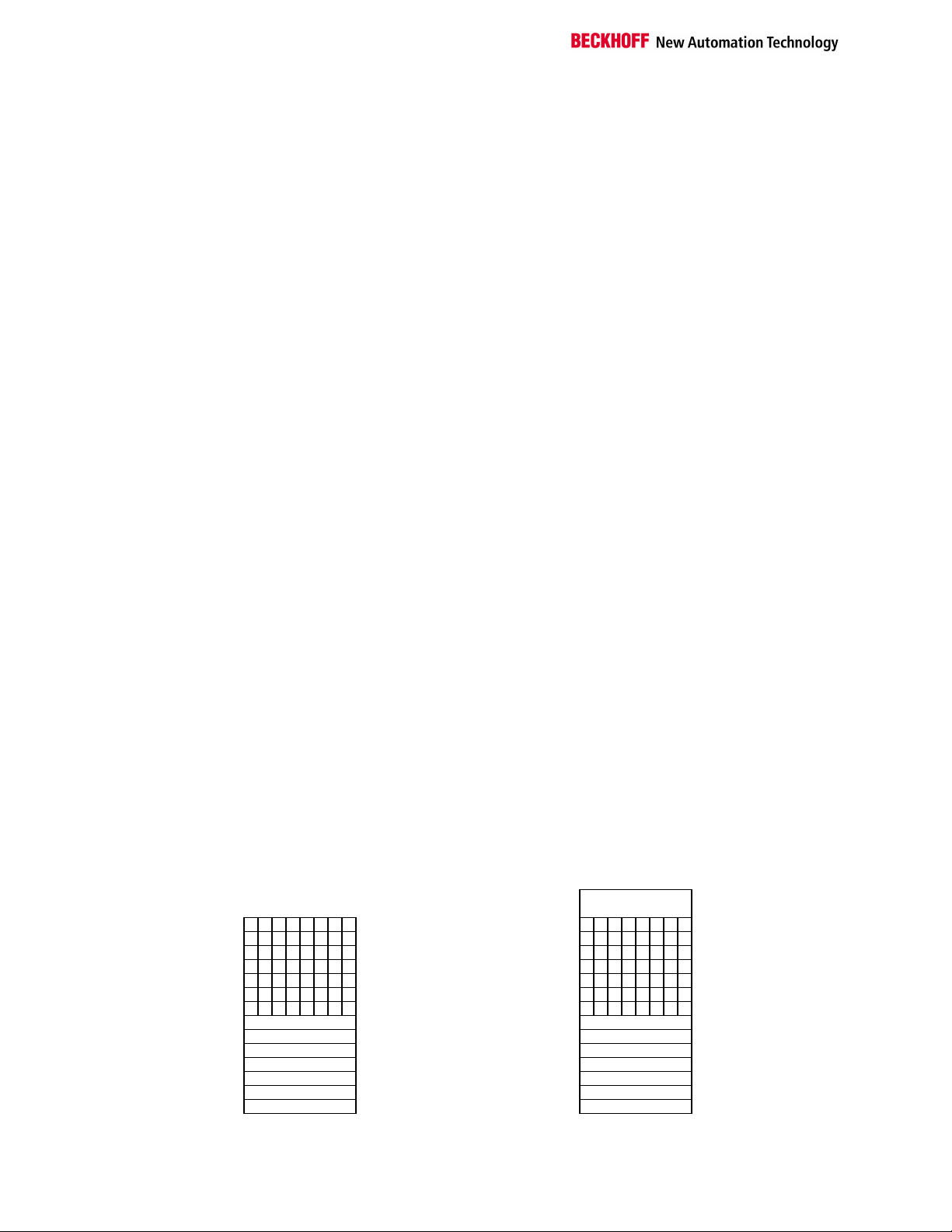
IO-Data which is transferred from the DeviceNet Master / Scanner to the
ILxxxx-B520 begins with byte-oriented values which is the data for the analog output and special signal extension boxes. The bit-oriented data for the
digital outputs of the ILxxxx-B520 and the digital output extension boxes is
transmitted after the byte-oriented data. If the total number of digital inputs
is not a multiple of 8, there will be a number of bits left over in the last data
byte. These will be discarded.
IO-Data which is transferred from the ILxxxx-B520 to the DeviceNet Master
/ Scanner begins with byte-oriented values which is the data from the analog input and special signal extension boxes. The bit-oriented data for the
digital inputs of the ILxxxx-B520 and the digital input extension boxes is
transmitted after the byte-oriented data. If the total number of digital outputs is not a multiple of 8, there will be a number of bits left over in the last
data byte. These will be discarded.
An extra status byte is transferred at the end of the Input Data and returns
the status of the ILxxxx-B520 with the following meaning:
Bit0: IL_Error : IO Error, internal Data exchange ILxxxx-B520 has failed
Bit1: IL-Cfg : ILxxxx-B520 Configuration Error
Bit2: reserved
Bit3: Diag : Diagnosis of analog Channel
Bit4: reserved
Bit5: reserved
Bit6: reserved
Bit7: FB_Error : Fieldbus Error / Idle Mode
The status byte corresponds to the Attribute “IL-Status” of the IL-Config
Object.
B520 to Master / Scanner
ILxxxx-B520 8
Page 12

2.1.1 IL230x-B520
Description
IO Data Type
Input Data
Output Data
4 x Digital Input + 4 x Digital Output, 24 V DC
Digital Signal, bit-oriented
4 Bit
4 Bit
2.1.2 IE100x
Description
IO Data Type
Input Data
Output Data
8 Channel Digital Input, 24 V DC
Digital Signal, bit-oriented
8 Bit
none
2.1.3 IE1502
Description
IO Data Type
Input Data
Output Data
2 Channel Up/Down Counter, 24 V DC, 100 kHz
Analog Signal, byte-oriented
10 Byte
Byte 0: Status, Channel 1
Byte 1: LowByte DataIn[0], Channel 1
Byte 2: HighByte DataIn[0], Channel 1
Byte 3: LowByte DataIn[1], Channel 1
Byte 4: HighByte DataIn[1], Channel 1
Byte 5: Status, Channel 2
Byte 6: LowByte DataIn[0], Channel 2
Byte 7: HighByte DataIn[0], Channel 2
Byte 8: LowByte DataIn[1], Channel 2
Byte 9: HighByte DataIn[1], Channel 2
10 Byte
Byte 0: Control, Channel 1
Byte 1: LowByte DataOut[0], Channel 1
Byte 2: HighByte DataOut [0], Channel 1
Byte 3: LowByte DataOut [1], Channel 1
Byte 4: HighByte DataOut [1], Channel 1
Byte 5: Control, Channel 2
Byte 6: LowByte DataOut [0], Channel 2
Byte 7: HighByte DataOut [0], Channel 2
Byte 8: LowByte DataOut [1], Channel 2
Byte 9: HighByte DataOut [1], Channel 2
(detailed description, see IE1502 manual)
IO Data Mapping
9 ILxxxx-B520
Page 13

IO Data Mapping
2.1.4 IE200x
Description
IO Data Type
Input Data
Output Data
8 Channel Digital Output, 24 V DC
Digital Signal, bit-oriented
none
8 Bit
2.1.5 IE230x
Description
IO Data Type
Input Data
Output Data
4 x Digital Input + 4 x Digital Output, 24 V DC
Digital Signal, bit-oriented
4 Bit
4 Bit
2.1.6 IE240x
Description
IO Data Type
Input Data
Output Data
8 Channel Digital Combi Input / Output, 24 V DC
Digital Signal, bit-oriented
8 Bit
8 Bit
2.1.7 IE3102
Description
IO Data Type
Input Data
Output Data
4 Channel Analog Input, ± 10 V
Analog Signal, byte-oriented
8 Byte
Byte 0: LowByte Channel 1
Byte 1: HighByte Channel 1
Byte 2: LowByte Channel 2
Byte 3: HighByte Channel 2
Byte 4: LowByte Channel 3
Byte 5: HighByte Channel 3
Byte 6: LowByte Channel 4
Byte 7: HighByte Channel 4
none
(detailed description, see IE3102 manual)
ILxxxx-B520 10
Page 14

2.1.8 IE3112
Description
IO Data Type
Input Data
Output Data
4 Channel Analog Input 0-20mA
Analog Signal, byte-oriented
8 Byte
Byte 0: LowByte Channel 1
Byte 1: HighByte Channel 1
Byte 2: LowByte Channel 2
Byte 3: HighByte Channel 2
Byte 4: LowByte Channel 3
Byte 5: HighByte Channel 3
Byte 6: LowByte Channel 4
Byte 7: HighByte Channel 4
none
(detailed description, see IE3112 manual)
2.1.9 IE3202
Description
IO Data Type
Input Data
Output Data
4 Channel Analog Input PT100 (RTD)
Analog Signal, byte-oriented
8 Byte
Byte 0: LowByte Channel 1
Byte 1: HighByte Channel 1
Byte 2: LowByte Channel 2
Byte 3: HighByte Channel 2
Byte 4: LowByte Channel 3
Byte 5: HighByte Channel 3
Byte 6: LowByte Channel 4
Byte 7: HighByte Channel 4
none
(detailed description, see IE3202 manual)
IO Data Mapping
11 ILxxxx-B520
Page 15

IO Data Mapping
2.1.10 IE3312
Description
IO Data Type
Input Data
Output Data
4 Channel Analog Input Thermoelement
Analog Signal, byte-oriented
8 Byte
Byte 0: LowByte Channel 1
Byte 1: HighByte Channel 1
Byte 2: LowByte Channel 2
Byte 3: HighByte Channel 2
Byte 4: LowByte Channel 3
Byte 5: HighByte Channel 3
Byte 6: LowByte Channel 4
Byte 7: HighByte Channel 4
none
(detailed description, see IE3312 manual)
2.1.11 IE4112
Description
IO Data Type
Input Data
Output Data
4 Channel Analog Output, 0... 20 mA
Analog Signal, byte-oriented
none
8 Byte
Byte 0: LowByte Channel 1
Byte 1: HighByte Channel 1
Byte 2: LowByte Channel 2
Byte 3: HighByte Channel 2
Byte 4: LowByte Channel 3
Byte 5: HighByte Channel 3
Byte 6: LowByte Channel 4
Byte 7: HighByte Channel 4
(detailed description, see IE4112 manual)
ILxxxx-B520 12
Page 16

2.1.12 IE4132
Description
IO Data Type
Input Data
Output Data
4 Channel Analog Output, -10 V / 0-10 V
Analog Signal, byte-oriented
none
8 Byte
Byte 0: LowByte Channel 1
Byte 1: HighByte Channel 1
Byte 2: LowByte Channel 2
Byte 3: HighByte Channel 2
Byte 4: LowByte Channel 3
Byte 5: HighByte Channel 3
Byte 6: LowByte Channel 4
Byte 7: HighByte Channel 4
(detailed description, see IE4132 manual)
2.1.13 IE5009
Description
IO Data Type
Input Data
Output Data
1 Channel SSI Sensor Interface
Analog Signal, byte-oriented
4 Byte
Byte 0: LowByte PCDL
Byte 1: HighByte PCDL
Byte 2: LowByte PCDH
Byte 3: HighByte PCDH
none
(detailed description, see IE5009 manual)
IO Data Mapping
13 ILxxxx-B520
Page 17

IO Data Mapping
2.1.14 IE5109
Description
IO Data Type
Input Data
Output Data
1 Channel Incremental Encoder Interface, 1 MHz
Analog Signal, byte-oriented
6 Byte
Byte 0: Status
Byte 1: Low Byte Counter
Byte 2: High Byte Counter
Byte 3: Latch
Byte 4: LowByte Period
Byte 5: HighByte Period
3 Byte
Byte 0: Control
Byte 1: Low Byte RegData
Byte 2: High Byte RegData
(detailed description, see IE5109 manual)
2.1.15 IE6002
Description
IO Data Type
Input Data
Output Data
1 Channel Serial Interface, RS232 C
Serial Signal, byte-oriented
6 Byte
Byte 0: Status
Byte 1: Data In 0
Byte 2: Data In 1
Byte 3: Data In 2
Byte 4: Data In 3
Byte 5: Data In 4
6 Byte
Byte 0: Control
Byte 1: Data In 0
Byte 2: Data In 1
Byte 3: Data In 2
Byte 4: Data In 3
Byte 5: Data In 4
(detailed description, see IE6002 manual)
ILxxxx-B520 14
Page 18

2.1.16 IE6012
Description
IO Data Type
Input Data
Output Data
1 Channel Serial Interface, 0...20mA (TTY)
Serial Signal, byte-oriented
6 Byte
Byte 0: Status
Byte 1: Data In 0
Byte 2: Data In 1
Byte 3: Data In 2
Byte 4: Data In 3
Byte 5: Data In 4
6 Byte
Byte 0: Control
Byte 1: Data In 0
Byte 2: Data In 1
Byte 3: Data In 2
Byte 4: Data In 3
Byte 5: Data In 4
(detailed description, see IE6012 manual)
2.1.17 IE6022
Description
IO Data Type
Input Data
Output Data
1 Channel Serial Interface, RS422 / RS485
Serial Signal, byte-oriented
6 Byte
Byte 0: Status
Byte 1: Data In 0
Byte 2: Data In 1
Byte 3: Data In 2
Byte 4: Data In 3
Byte 5: Data In 4
6 Byte
Byte 0: Control
Byte 1: Data In 0
Byte 2: Data In 1
Byte 3: Data In 2
Byte 4: Data In 3
Byte 5: Data In 4
(detailed description, see IE6022 manual)
IO Data Mapping
15 ILxxxx-B520
Page 19

IO Data Mapping
2.2 IO Mapping Example
The example below shows the IO-Data mapping with default IO-Assignment:
Configuration
Input Data
IL2301 +
IE1001 +
IE2001 +
IE2401 +
IE3102 +
IE4112
12 Byte
Byte 0 :IE3102, Low Byte Channel 1
Byte 1 :IE3102, High Byte Channel 1
Byte 2 :IE3102, Low Byte Channel 2
Byte 3 :IE3102, High Byte Channel 2
Byte 4 :IE3102, Low Byte Channel 3
Byte 5 :IE3102, High Byte Channel 3
Byte 6 :IE3102, Low Byte Channel 4
Byte 7 :IE3102, High Byte Channel 4
Byte 8 :
Bit 0: IL2301, Bit0
Bit 1: IL2301, Bit1
Bit 2: IL2301, Bit2
Bit 3: IL2301, Bit3
Bit 4: IE1001, Bit0
Bit 5: IE1001, Bit1
Bit 6: IE1001, Bit2
Bit 7: IE1001, Bit3
Byte 9 :
Bit 0: IE1001, Bit0
Bit 1: IE1001, Bit1
Bit 2: IE1001, Bit2
Bit 3: IE1001, Bit3
Bit 4: IE2401, Bit0
Bit 5: IE2401, Bit1
Bit 6: IE2401, Bit2
Bit 7: IE2401, Bit3
Byte 10 :
Bit 0: IE2401, Bit4
Bit 1: IE2401, Bit5
Bit 2: IE2401, Bit6
Bit 3: IE2401, Bit7
Bit 4: not used
Bit 5: not used
Bit 6: not used
Bit 7: not used
Byte 11 :IL-Status Byte
Bit0: IL_Error
Bit1: IL-Cfg
Bit2: reserved
Bit3: Diag
Bit4: reserved
Bit5: reserved
Bit6: reserved
Bit7:FB_Error
ILxxxx-B520 16
Page 20

IO Data Mapping
Output Data
11 Byte
Byte 0 :IE4112, Low Byte Channel 1
Byte 1 :IE4112, High Byte Channel 1
Byte 2 :IE4112, Low Byte Channel 2
Byte 3 :IE4112, High Byte Channel 2
Byte 4 :IE4112, Low Byte Channel 3
Byte 5 :IE4112, High Byte Channel 3
Byte 6 :IE4112, Low Byte Channel 4
Byte 7 :IE4112, High Byte Channel 4
Byte 8 :
Bit 0: IL2301, Bit0
Bit 1: IL2301, Bit1
Bit 2: IL2301, Bit2
Bit 3: IL2301, Bit3
Bit 4: IE2001, Bit0
Bit 5: IE2001, Bit1
Bit 6: IE2001, Bit2
Bit 7: IE2001, Bit3
Byte 9 :
Bit 0: IE2001, Bit4
Bit 1: IE2001, Bit5
Bit 2: IE2001, Bit6
Bit 3: IE2001, Bit7
Bit 4: IE2401, Bit0
Bit 5: IE2401, Bit1
Bit 6: IE2401, Bit2
Bit 7: IE2401, Bit3
Byte 10 :
Bit 0: IE2401, Bit4
Bit 1: IE2401, Bit5
Bit 2: IE2401, Bit6
Bit 3: IE2401, Bit7
Bit 4: not used
Bit 5: not used
Bit 6: not used
Bit 7: not used
17 ILxxxx-B520
Page 21

IO Data Mapping
2.3 Assembly Objects
The Assembly Object binds attributes of multiple objects, which allows data to or from each object to be sent
or received over a single connection (IO or Explicit). Assembly objects are used to bind input data and output
data.
Class Code: 4 (04
Class Attributes
Attribute
ID
1 Get Revision UINT Revision of implementation 2
Instance Attributes
Attribute
ID
3
(03hex)
Common Services
Service Code Service Name Description
IO Assembly Instances
Number Type Name
101 Output Analog and Digital Outputs
102 Output Digital Outputs
103 Output Analog Outputs
111 Input Analog and Digital Inputs and Status Byte
112 Input Digital Inputs and Status Byte
113 Input Analog Inputs and Status Byte
Access
Rule
Access
Rule
Get/set Value Array of
14
(0Ehex)
16
(10hex)
hex
)
Name Data
Name Data
Byte
Get_Attribute_Single Returns the contents of the specified
Set_Attribute_Single Modifies an attribute Value
Type
Type
Description Semantics of
Description Semantics of
Input or Output Data of the
ILxxxx-B520.
attribute
Value
Value
ILxxxx-B520 18
Page 22

IO Data Mapping
2.3.1 Input Assembly
Default Instance
Number Byte Bit 7 Bit 6 Bit 5 Bit 4 Bit 3 Bit 2 Bit 1 Bit 0
111 0 to (n-1) Analog Inputs
n to (m-1) Digital Inputs
m IL-Status Byte
Number Byte Bit 7 Bit 6 Bit 5 Bit 4 Bit 3 Bit 2 Bit 1 Bit 0
112 0 to (n-1) Digital Inputs
n IL-Status Byte
Number Byte Bit 7 Bit 6 Bit 5 Bit 4 Bit 3 Bit 2 Bit 1 Bit 0
113 0 to (n-1) Analog Inputs
n IL-Status Byte
2.3.2 Output Assembly
Default Instance
Number Byte Bit 7 Bit 6 Bit 5 Bit 4 Bit 3 Bit 2 Bit 1 Bit 0
101 0 to (n-1) Analog Outputs
n to m Digital Outputs
Number Byte Bit 7 Bit 6 Bit 5 Bit 4 Bit 3 Bit 2 Bit 1 Bit 0
102 n Digital Outputs
Number Byte Bit 7 Bit 6 Bit 5 Bit 4 Bit 3 Bit 2 Bit 1 Bit 0
103 n Analog Outputs
2.3.3 Mapping IO Assembly Data to DeviceNet Objects
Data Component Name 2.3.3.1.1.1 Class Instance Attribute
Name Number Name Number
Discrete Input n Digital Input Channel 101 n Value 1
Discrete Output n Digital Output Channel 102 n Value 1
Analog Input n Analog Input Channel 103 n Value 1
Analog Output n Analog Output Channel 104 n Value 1
IL-Status Byte IL Config Object 100 1 IL-Status 5
19 ILxxxx-B520
Page 23

IL Config Object
3 IL Config Object
IL Config Object
The IL Config Object Class is Vendor specific and within in the Range of
Class Code: 100 (64
Class Attributes
Attribute
ID
1 Get Revision UINT Revision of implementation 1
2 Get Max. Instance UINT Max. number of instances 1
Instance Attributes
Attribute
ID
1 Get/Set Terminal
2 Get/Set Table Number USINT Number of table See ILxxxx-B520
3 Get/Set Register Num-
4 Get/Set Register Data DWORD Register Value see semantics
5 Get IL-Status BYTE Status of the ILxxxx-B520 see semantics
6 Get Extension Box10 Get/Set IO Error Action BYTE Action to be performed if a
11 Get/Set Poll produced
12 Get/Set COS/ Cyclic
13 Get/Set Bit Strobe pro-
14 Get/Set Poll / COS/
Access
Rule
Access
Rule
The ILxxxx-B520 provides the vendor specific object class to access its
status, diagnostic and configuration data. Within the IL Config Object the
full range of Registers and Status-Information of the ILxxxx-B520 and the
connected extension boxes is available.
the Vendor specific Class Codes.
)
hex
Name Data
Name Data
Number
ber
Diagnosis
data type
produced data
type
duced data
type
Cyclic con-
sumed data
type
Type
Type
USINT Number of terminal 0: Coupler
USINT Number of Register See ILxxxx-B520
WORD Diagnosis of the extension
boxes
fieldbus error occurs
BYTE Type of IO data produced
via the Poll mode
BYTE Type of IO data produced
via the Change of State /
Cyclic mode
BYTE Type of IO data produced
via the Bit Strobe / Cyclic
mode
BYTE Type of IO data con-
sumed via the Poll /
Change of State / Cyclic
mode
Description Semantics of
Description Semantics of
Value
>0: Channels
/Channel Descrip-
tion
/Channel Descrip-
tion
see semantics
see semantics
see semantics
see semantics
see semantics
see semantics
Value
ILxxxx-B520 20
Page 24

IL Config Object
Instance Attributes
Attribute
ID
15 Get Input Size Poll
16 Get Input Size Bit
Access
Rule
Name Data
BYTE Number of Bytes pro-
Mode
BYTE Number of Bytes pro-
Strobe Mode
Type
Description Semantics of
Value
duced via the Poll mode
duced via the Bit Strobe
mode
17 Get Input Size COS
/ Cyclic Mode
BYTE Number of Bytes pro-
duced via the Change of
State / Cyclic mode
18 Get Output Size
Poll / COS/
Cyclic Mode
BYTE Number of Bytes con-
sumed via the Poll /
Change of State /Cyclic
mode
19 Get/Set Device Diag-
nostics
BYTE Enables Diagnosis of
complex (analog/special-
see semantics
function) extension boxes
20 Get Analog Out
Length
21 Get Analog In
Length
22 Get Digital In
Length
23 Get Digital Out
Length
25 Get/Set Bus Off
Behavior
BYTE Size of analog output data
in bits
BYTE Size of analog input data
in bits
BYTE Size of digital output data
in bits
BYTE Size of digital input data in
Bits
BYTE Behavior of ILxxxx-B520
after detection of a Bus-
see semantics
Off event
Semantics
Register Data
Within the response of a Get_Attribute_Single Service to the „Register
Data“ Attribute the status of the internal reading and the registers data is
returned by the ILxxxx-B520. The meaning of the registers data is described in the ILxxxx-B520 manual.
Within the request of a Set_Attribute_Single Service to the „Register Data“
Attribute the Low-Word of the attribute „RegisterData“ is used to send the
Register data to the ILxxxx. The meaning of the registers data is described
in the ILxxxx-B520 manual.
Response Data of Get_Attribute_Single
Byte Bit 7 Bit 6 Bit 5 Bit 4 Bit 3 Bit 2 Bit 1 Bit 0
0 Status (Low Byte)
1 Status (High Byte) : 0 = OK, >0 = Error
2 Register data (Low Byte)
3 Register data (High Byte)
21 ILxxxx-B520
Page 25

IL Config Object
Request Data of Set_Attribute_Single
Byte Bit 7 Bit 6 Bit 5 Bit 4 Bit 3 Bit 2 Bit 1 Bit 0
0 Register data (Low Byte)
1 Register data (High Byte)
2 Not used
3 Not used
Response Data of Set_Attribute_Single
Byte Bit 7 Bit 6 Bit 5 Bit 4 Bit 3 Bit 2 Bit 1 Bit 0
0 Status (Low Byte)
1 Status (High Byte) : 0 = OK, >0 = Error
IL_Status
The „IL Status“ attribute shows the actual status of the ILxxxx-B520.
Byte Bit 7 Bit 6 Bit 5 Bit 4 Bit 3 Bit 2 Bit 1 Bit 0
Byte FB_Error
res. res. res. Diag res. IL_Cfg IL_Error
IL_Error : IO Error, internal Data exchange ILxxxx-B520 has failed
IL_Cfg : ILxxxx-B520 Configuration Error (EEPROM check failed)
Diag : Diagnosis of analog Channel
FB_Error : Fieldbus Error / Idle Mode
Extension Box Diagnosis
The „Extension Box Status“ attribute describes which of the extension boxes has encountered a diagnosis event. After reading the extension box
Status, the attribute is cleared until the next diagnosis appears. Reading of the attribute also clears the “Diag-Bit” within the attribute “IL
Status”. The function of this attribute is only active if the diagnosis of
analog extension boxes is enabled.
Byte Bit 7 Bit 6 Bit 5 Bit 4 Bit 3 Bit 2 Bit 1 Bit 0
0 Extension Box Number
1 Status Error Code Channel Number
Extension Box Number : Number of failed extension box
Channel Number : Number of failed channel of the extension box
Error Code : Extension box specific Error Code (see extension box manual)
Status : 0 = Error is reseted
1 = Error occurred
ILxxxx-B520 22
Page 26

Enables Diagnostics of complex (analog/special function) extension boxes.
IO Error Action
Note
Action to be performed if a fieldbus error occurred.
To activate a new IO error Action setting a device reset has to be performed either by executing a power cycle to the ILxxxx-B520 or by
executing a Reset Service (Service Code 5) to the ILxxxx-B520 Identity Object (Class Id 1, Instance 1)
Value
0
1
2
- Poll produced data type
- COS / Cyclic produced
Type of IO data produced/consumed via the Poll mode and Change of
State / Cyclic mode
data type
- Poll / COS / Cylic
consumed data type
Value
0
1
2
- Bit Strobe produced
Type of IO data produced via the Bit Strobe mode
data type
Value
0
1
Device Diagnostics
Note
Setting this attribute enables the diagnosis of complex channels which is
needed to read the extension box diagnosis.
To activate the diagnosis functions a device reset has to be performed either by executing a power cycle to the ILxxxx-B520 or executing a Reset Service (Service Code 5)to the Identity Object (Class Id
1, Instance 1)
Value
0
1
IL Config Object
Description
Leave local IO Cycle
Leave local IO Cycle and reset outputs (default)
freeze outputs
Description
Analog and digital IO Data with Status Byte (default)
Digital IO Data with Status Byte
Analog IO Data with Status Byte
Description
Diagnostic Data (see Attribute extension box diagnosis)
Digital Inputs with Status Byte (default)
Description
Device Diagnostic OFF (default)
Device Diagnostic ON
23 ILxxxx-B520
Page 27

IL Config Object
Bus Off Behavior
Note
Defines the Behavior of the ILxxxx-B520 after detection of a Bus-Off event.
This attribute is available from Firmware Revision 1.2 upwards
Value
0
1
Description
Hold the ILxxxx-B520 in Bus-Off State (default)
Reset ILxxxx-B520 and restart communication. After detection
of 255 Bus-Off events the ILxxxx-B520 keeps in the reset state.
ILxxxx-B520 24
Page 28

Digital Input Channel Object
4 Digital Input Channel Object
Digital Input Channels
The Digital Input Channel Object Class is Vendor specific and within in the
Class Code: 101 (65
Class Attributes
Attribute
ID
Access
Rule
1 Get Revision UINT Revision of implementation 1
2 Get Max. Instance UINT Max. number of instances
Instance Attributes
Attribute
ID
1
Access
Rule
Get Value BOOL Input Channel Value 0: OFF
(01hex)
Common Services
Service Code Service Name Description
14
(0Ehex)
The ILxxxx-B520 provides Digital Input Channel Objects to access the
digital input channels data of the ILxxxx-B520 and the connected extension
boxes. For each digital input channel exits one instance of the Digital Input
Channel Object Class.
range of the Vendor specific Class Codes.
)
hex
Name Data
Type
Name Data
Type
Description Semantics of
Value
Description Semantics of
Value
1: ON
Get_Attribute_Single Returns the contents of the specified
attribute
25 ILxxxx-B520
Page 29

Digital Output Channel Object
5 Digital Output Channel Object
Digital Output Channels
The Digital Output Channel Object Class is Vendor specific and within in
Class Code: 102 (66
Class Attributes
Attribute
ID
1 get Revision UINT Revision of implementation 1
2 get Max. Instance UINT Max. number of instances
Instance Attributes
Attribute
ID
1
(01hex)
Common Services
Service Code Service Name Description
Access
Rule
Access
Rule
Get/Set Value BOOL Output Channel Value 0: OFF
14
(0Ehex)
16
(10hex)
The ILxxxx-B520 provides Digital Output Channel Objects to access the
digital output channels data of the ILxxxx-B520 and the connected extension boxes. For each digital output channel exits one instance of the Digital
Output Channel Object Class.
the range of the Vendor specific Class Codes.
)
hex
Name Data
Type
Name Data
Type
Get_Attribute_Single Returns the contents of the specified
Set_Attribute_Single Modifies an attribute Value
Description Semantics of
Value
Description Semantics of Value
1: ON
attribute
ILxxxx-B520 26
Page 30

Analog Input Channel Object
6 Analog Input Channel Object
Analog Input Channel
The Analog Input Channel Object Class is Vendor specific and within in the
Class Code: 103 (67
Class Attributes
Attribute
ID
1 get Revision UINT Revision of implementation 1
2 get Max. Instance UINT Max. number of instances
Instance Attributes
Attribute
ID
1
(01hex)
2
(02hex)
100
(64hex)
Access
Rule
Access
Rule
get Value Array of
get Value Length USINT Value length in Bytes
get/set1 Register 0 DWORD Value of Register 0 of
The Analog Input Channel Class allows the access to the IO-Data and the
Register Data of each analog channel of the ILxxxx-B520 and the connected extension boxes. At Boot Up the ILxxxx-B520 determines the number of analog input channels and creates one instance of the object class
for each channel.
range of the Vendor specific Class Codes.
)
hex
Name Data
Type
Name Data
Type
BYTE
Value of analog input
channel
the analog input channel
Description Semantics of
Value
Description Semantics of Value
Number of Bytes
differs between analog and special signal
extension boxes
see semantics
: : : : : :
106
(6Ahex)
get Register 6 DWORD Diagnosis Register see semantics
: : : : : :
163
(A3hex)
1: before writing the registers the write protection of the registers has to be disabled.
get/set1 Register 63 DWORD Value of Register 63 of
the analog input channel
see semantics
27 ILxxxx-B520
Page 31

Analog Input Channel Object
Semantics
Register 0 – 63
Within the response of a Get_Attribute_Single Service to the „Register
Data“ Attribute the status of the internal reading and the registers data is
returned by the ILxxxx-B520. The meaning of the registers data is described in the ILxxxx-B520 manual.
Within the response of a Set_Attribute_Single Service to the „Register Data“ Attribute the status of the internal reading is returned by the ILxxxxB520.
Get_Attribute Response
Byte Bit 7 Bit 6 Bit 5 Bit 4 Bit 3 Bit 2 Bit 1 Bit 0
0 Status (Low Byte)
1 Status (High Byte) : 0 = OK, >0 = Error
2 Register data (Low Byte)
3 Register data (High Byte)
Set_Attribute Request
Byte Bit 7 Bit 6 Bit 5 Bit 4 Bit 3 Bit 2 Bit 1 Bit 0
0 Register data (Low Byte)
1 Register data (High Byte)
2 Not used
3 Not used
Set_Attribute Response
Byte Bit 7 Bit 6 Bit 5 Bit 4 Bit 3 Bit 2 Bit 1 Bit 0
0 Status (Low Byte)
1 Status (High Byte) : 0 = OK, >0 = Error
Common Services
Service Code Service Name Description
14
(0Ehex)
16
Get_Attribute_Single Returns the contents of the specified
attribute
Set_Attribute_Single Modifies an attribute Value
(10hex)
ILxxxx-B520 28
Page 32

Analog Output Channel Object
7 Analog Output Channel Object
Analog Output Channels
The Analog Output Channel Object Class is Vendor specific and within in
Class Code: 104 (68
Class Attributes
Attribute
ID
1 get Revision UINT Revision of implementation 1
2 get Max. Instance UINT Max. number of instances
Instance Attributes
Attribute
ID
1
(01hex)
2
(02hex)
100
(64hex)
Access
Rule
Access
Rule
Get/set Value Array of
get Value Length USINT Value length in Bytes
get/set1 Register 0 DWORD Value of Register 0 of
The Analog Output Channel Class allows the access to the IO-Data and
the Register Data of each analog output channel of the ILxxxx-B520 and
the connected extension boxes. At Boot Up the ILxxxx-B520 determines
the number of analog output channels and creates one instance of the
object class for each channel.
the range of the Vendor specific Class Codes.
)
hex
Name Data
Type
Name Data
Type
BYTE
Value of analog output
channel
the analog output
channel
Description Semantics of
Value
Description Semantics of Value
Number of Bytes
differs between analog and special signal
extension boxes
see semantics
: : : : : :
106
(6Ahex)
get Register 6 DWORD Diagnosis Register see semantics
: : : : : :
163
(A3hex)
1: before writing the registers the write protection of the registers has to be disabled.
get/set1 Register 63 DWORD Value of Register 63 of
the analog output
channel
see semantics
29 ILxxxx-B520
Page 33

Analog Output Channel Object
Semantics
Register 0 – 63
Within the response of a Get_Attribute_Single Service to the „Register
Data“ Attribute the status of the internal reading and the registers data is
returned by the ILxxxx-B520. The meaning of the registers data is described in the ILxxxx-B520 manual.
Within the response of a Set_Attribute_Single Service to the „Register Data“ Attribute the status of the internal reading is returned by the coupler.
Get_Attribute Response
Byte Bit 7 Bit 6 Bit 5 Bit 4 Bit 3 Bit 2 Bit 1 Bit 0
0 Status (Low Byte)
1 Status (High Byte) : 0 = OK, >0 = Error
2 Register data (Low Byte)
3 Register data (High Byte)
Set_Attribute Request
Byte Bit 7 Bit 6 Bit 5 Bit 4 Bit 3 Bit 2 Bit 1 Bit 0
0 Register data (Low Byte)
1 Register data (High Byte)
2 Not used
3 Not used
Set_Attribute Response
Byte Bit 7 Bit 6 Bit 5 Bit 4 Bit 3 Bit 2 Bit 1 Bit 0
0 Status (Low Byte)
1 Status (High Byte) : 0 = OK, >0 = Error
Common Services
Service Code Service Name Description
14
(0Ehex)
16
Get_Attribute_Single Returns the contents of the specified
attribute
Set_Attribute_Single Modifies an attribute Value
(10hex)
ILxxxx-B520 30
Page 34

8 Indicators and Switches
8.1 Start-up procedure and Diagnostics LEDs
Start-up procedure and
Diagnostic
The diagnostic LEDs
Local errors
Blink code
Error location
After switching on, the ILxxxx-B520 immediately checks the connected
configuration. Error-free start-up is signalled by the red "I/O ERR“ LED
being extinguished. If the “I/O ERR” LED blinks, an error in the area of the
extension boxes is indicated. The error code can be determined from the
frequency and number of blinks. This permits rapid rectification of the error.
There is a detailed description in the section on "The diagnostic LEDs".
The ILxxxx-B520 has two groups of LEDs for the display of status. The
upper group with two LEDs indicates the status of the respective fieldbus.
The significance of the “fieldbus status“ LED is explained in the relevant
sections of this manual - it conforms to conventional fieldbus displays.
On the bottom of the ILxxxx-B520 are two more green LEDs that indicate
the supply voltage. The left hand LED indicates the presence of the 24 V
supply for the ILxxxx-B520. The right hand LED indicates the presence of
the supply to the power contacts.
Two LEDs, the “I/O LEDs”, in the area below the field bus status LEDs
referred to above, serve to indicate the operating status of the ILxxxx-B520
and the connected extension boxes. The green LED lights up in order to
indicate fault-free operation. The red LED blinks with two different frequencies in order to indicate an error. The error is encoded in the blinks as follows:
Fast blinking
First slow sequence
Second slow sequence
Error code Error code ar-
gument
1 pulse
2 pulses
3 pulses
4 pulses
5 pulses
6 pulses
11 pulses
12 pulses
13 pulses
0
1
2
0
n (n > 0)
0
n
0
n
n IP-Link bus error in register communication with
0
n (n > 0)
n IR Error, no communication, extension box n is
n More than 120 extension boxes
n unknown box type, extension box n
Start of the error code
Error code
Error code argument
Description
EEPROM checksum error
Inline code buffer overflow
Unknown data type
Programmed configuration
Incorrect table entry / Ilxxxx-B520
Incorrect table comparison (extension box n)
Interruption of IP-Link bus
Break behind extension box (0: ILxxxx-B520)
IP-Link bus data error (incorrect telegram)
Extension box n (0: Ilxxxx-B520)
extension box n
Special fieldbus error
not processing the IR commands
n extension boxes too much
The number of pulses in the first sequence indicates the error type, while
Indicators and Switches
31 ILxxxx-B520
Page 35

Indicators and Switches
the second sequence indicates the position of the last extension box before
the fault.
In the case of some errors, rectification does not cause the ILxxxx-B520 to
leave the blink sequence. The ILxxxx-B520 stays in the "Stop" state. The
ILxxxx-B520 can only be re-started either by switching the power supply off
and on again, or by a scanner reset.
8.2 Fieldbus / DeviceNet LEDs
DeviceNet Status LED
The LED pair is located next to the configuration interface for adjustment of
States of Module / Status
LED
The red/green LED pair provides information about the device and communication status of the ILxxxx-B520. The LEDs acts as the bi-color combined Module/Network Status LED defined in the DeviceNet Specification.
the DeviceNet address (MacId)
LED State Description
Green Flashing
Green ON
Green OFF
Red Flashing
Red ON
Red OFF
Boot Up OK, Device has executed Duplicate MacId Check and
is ON-Line. The ILxxxx-B520 is not allocated by a Master /
Scanner, no Data Exchange with a Master / Scanner
No Error, ILxxxx-B520 is allocated by a Master / Scanner, Data
Exchange (Explicit or IO) with Master / Scanner is OK
- Bus Sense Error (24V DeviceNet Voltage in not available)
(all LEDs off, including IO-Run, IO-Error LEDs)
- No BaudRate, ILxxxx-B520 is not able to detect BaudRate
(IO-Run, IO-Error LEDs On)
Time Out, IO-Connection has timed out
- Duplicate MacId Fault, check for same Address in Network
- Bus-Off, check cabling, check bus termination, check bus
length
- Receive/Transmit Overrun, reduce IO-Cycle Time / Interscan
delay at Master / Scanner
- Bus Sense Error (24V DeviceNet Voltage in not available)
(all LEDs off, including IO-Run, IO-Error LEDs)
- No BaudRate, ILxxxx-B520 is not able to detect BaudRate
(IO-Run, IO-Error LEDs On)
ILxxxx-B520 32
Page 36

8.3 DeviceNet Node Address Switches
Node Address Switches
Node Address Switch
For further information please contact your local Beckhoff representative or
Support North America
Phone +1 (9 52) 8 90 00 00
Fax +1 (9 52) 8 90 28 88
Mail support.usa@beckhoff.com
Support Europe
Phone: ++49 5246 963 157
Fax: ++49 5246 963 199
Mail: Support@beckhoff.com
The Node Address Switches consist of two, ten position rotary switches
within the Configuration Interface of the ILxxxx-B520
Node Address Description
0 - 63
> 63
Node Address from Switches is valid, not programmable
Node Address is programmable by Master / Scanner
Indicators and Switches
33 ILxxxx-B520
Page 37

Appendix
9 Appendix
9.1 Support and Service
Beckhoff and their partners around the world offer comprehensive support and service, making available fast
and competent assistance with all questions related to Beckhoff products and system solutions.
9.1.1 Beckhoff's branch offices and representatives
Please contact your Beckhoff branch office or representative for local support and service on Beckhoff products!
The addresses of Beckhoff's branch offices and representatives round the world can be found on her internet
pages: http://www.beckhoff.com
You will also find further documentation for Beckhoff components there.
9.2 Beckhoff Headquarters
Beckhoff Automation GmbH
Eiserstr. 5
33415 Verl
Germany
phone: + 49 (0) 5246/963-0
fax: + 49 (0) 5246/963-198
e-mail: info@beckhoff.com
web: www.beckhoff.com
9.2.1.1.1 Beckhoff Support
Support offers you comprehensive technical assistance, helping you no only with the application of individual
Beckhoff products, but also with other, wide-ranging services:
• support
• design, programming and commissioning of complex automation systems
• and extensive training program for Beckhoff system components
hotline: + 49 (0) 5246/963-157
fax: + 49 (0) 5246/963-9157
e-mail: support@beckhoff.com
9.2.1.1.2 Beckhoff Service
The Beckhoff Service Center supports you in all matters of after-sales service:
• on-site service
• repair service
• spare parts service
• hotline service
hotline: + 49 (0) 5246/963-460
fax: + 49 (0) 5246/963-479
e-mail: service@beckhoff.com
ILxxxx-B520 34
 Loading...