

Page 1
Documentation | EN
IL230x-B110
Fieldbus Box for EtherCAT
2017-05-29 | Version: 1.0.3
Page 2

Page 3

Table of contents
Table of contents
1 Foreword ....................................................................................................................................................5
1.1 Notes on the documentation..............................................................................................................5
1.2 Safety instructions .............................................................................................................................6
1.3 Documentation issue status ..............................................................................................................7
1.4 Bus Coupler as a general term..........................................................................................................7
2 Basics .........................................................................................................................................................8
2.1 System Properties .............................................................................................................................8
2.2 CoE Interface...................................................................................................................................11
2.3 EtherCAT State Machine.................................................................................................................13
3 Product overview.....................................................................................................................................15
3.1 The Fieldbus Box System................................................................................................................15
3.2 Fieldbus Box - Naming conventions ................................................................................................17
3.3 Firmware and hardware issue status...............................................................................................19
3.4 Technical data .................................................................................................................................20
4 Mounting and wiring................................................................................................................................21
4.1 Dimensions......................................................................................................................................21
4.2 EtherCAT connection ......................................................................................................................23
5 Parameterizning and commissioning....................................................................................................25
5.1 Start-up behavior of the Fieldbus Box .............................................................................................25
6 Configuration ...........................................................................................................................................26
6.1 TwinCAT System Manager..............................................................................................................26
6.1.1 Configuration overview .................................................................................................... 26
6.2 Objects ............................................................................................................................................36
6.2.1 Object description ............................................................................................................ 36
6.3 Configuration of the complex modules ............................................................................................51
6.3.1 General Register Description........................................................................................... 51
6.3.2 Example for Register Communication ............................................................................. 54
6.4 ADS communication ........................................................................................................................57
6.4.1 Parameterization example with KS2000.......................................................................... 57
7 Error handling and diagnosis.................................................................................................................61
7.1 Diagnostic LEDs - Overview............................................................................................................61
7.2 Diagnostic LEDs ..............................................................................................................................62
7.3 Diagnostic LEDs for local errors ......................................................................................................65
7.4 Check of the IP-Link connection......................................................................................................67
8 Accessories .............................................................................................................................................70
8.1 Fieldbus Box accessories................................................................................................................70
8.2 Power cables ...................................................................................................................................71
9 Appendix ..................................................................................................................................................72
9.1 General operating conditions...........................................................................................................72
9.2 Approvals.........................................................................................................................................73
9.3 Test standards for device testing.....................................................................................................73
9.4 Support and Service ........................................................................................................................74
IL230x-B110 3Version: 1.0.3
Page 4

Table of contents
IL230x-B1104 Version: 1.0.3
Page 5

Foreword
1 Foreword
1.1 Notes on the documentation
Intended audience
This description is only intended for the use of trained specialists in control and automation engineering who
are familiar with the applicable national standards.
It is essential that the documentation and the following notes and explanations are followed when installing
and commissioning these components.
It is the duty of the technical personnel to use the documentation published at the respective time of each
installation and commissioning.
The responsible staff must ensure that the application or use of the products described satisfy all the
requirements for safety, including all the relevant laws, regulations, guidelines and standards.
Disclaimer
The documentation has been prepared with care. The products described are, however, constantly under
development.
We reserve the right to revise and change the documentation at any time and without prior announcement.
No claims for the modification of products that have already been supplied may be made on the basis of the
data, diagrams and descriptions in this documentation.
Trademarks
Beckhoff®, TwinCAT®, EtherCAT®, EtherCATG®, EtherCATG10®, EtherCATP®, SafetyoverEtherCAT®,
TwinSAFE®, XFC®, XTS® and XPlanar® are registered trademarks of and licensed by Beckhoff Automation
GmbH. Other designations used in this publication may be trademarks whose use by third parties for their
own purposes could violate the rights of the owners.
Patent Pending
The EtherCAT Technology is covered, including but not limited to the following patent applications and
patents: EP1590927, EP1789857, EP1456722, EP2137893, DE102015105702 with corresponding
applications or registrations in various other countries.
EtherCAT® is registered trademark and patented technology, licensed by Beckhoff Automation GmbH,
Germany.
Copyright
© Beckhoff Automation GmbH & Co. KG, Germany.
The reproduction, distribution and utilization of this document as well as the communication of its contents to
others without express authorization are prohibited.
Offenders will be held liable for the payment of damages. All rights reserved in the event of the grant of a
patent, utility model or design.
IL230x-B110 5Version: 1.0.3
Page 6
Foreword
1.2 Safety instructions
Safety regulations
Please note the following safety instructions and explanations!
Product-specific safety instructions can be found on following pages or in the areas mounting, wiring,
commissioning etc.
Exclusion of liability
All the components are supplied in particular hardware and software configurations appropriate for the
application. Modifications to hardware or software configurations other than those described in the
documentation are not permitted, and nullify the liability of Beckhoff Automation GmbH & Co. KG.
Personnel qualification
This description is only intended for trained specialists in control, automation and drive engineering who are
familiar with the applicable national standards.
Description of instructions
In this documentation the following instructions are used.
These instructions must be read carefully and followed without fail!
DANGER
Serious risk of injury!
Failure to follow this safety instruction directly endangers the life and health of persons.
WARNING
Risk of injury!
Failure to follow this safety instruction endangers the life and health of persons.
CAUTION
Personal injuries!
Failure to follow this safety instruction can lead to injuries to persons.
NOTE
Damage to environment/equipment or data loss
Failure to follow this instruction can lead to environmental damage, equipment damage or data loss.
Tip or pointer
This symbol indicates information that contributes to better understanding.
IL230x-B1106 Version: 1.0.3
Page 7

Foreword
1.3 Documentation issue status
Version Comment
1.0.3 • Translation of chapter Diagnostic LEDs for
EtherCAT corrected
1.0.2 • System overview updated
• Description of CoE Interface updated
1.0.1 • EtherCAT connection updated
1.0 • First release
1.4 Bus Coupler as a general term
Parts of this manual give general information about Ethernet implementation in Beckhoff products.
Thus in the following often the term Bus Coupler is used, that describes not only the IP20 products, but also
means the IP67 modules.
IL230x-B110 7Version: 1.0.3
Page 8
Basics
2 Basics
2.1 System Properties
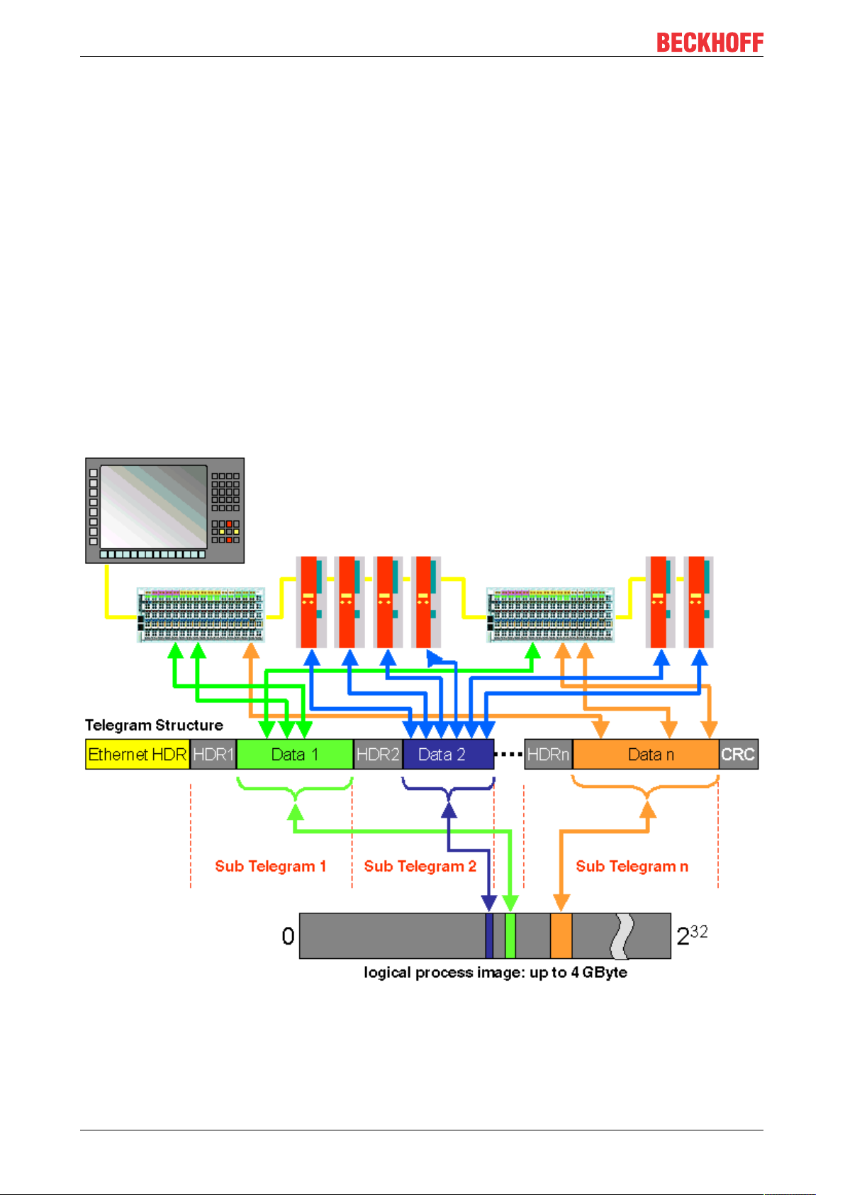
Protocol
The EtherCAT protocol is optimized for process data and is transported directly within the Ethernet frame
thanks to a special Ether-type. It may consist of several sub-telegrams, each serving a particular memory
area of the logical process images that can be up to 4 gigabytes in size. The data sequence is independent
of the physical order of the Ethernet terminals in the network; addressing can be in any order. Broadcast,
Multicast and communication between slaves are possible. Transfer directly in the Ethernet frame is used in
cases where EtherCAT components are operated in the same subnet as the control computer.
However, EtherCAT applications are not limited to a subnet: EtherCAT UDP packs the EtherCAT protocol
into UDP/IP datagrams. This enables any control with Ethernet protocol stack to address EtherCAT systems.
Even communication across routers into other subnets is possible. In this variant, system performance
obviously depends on the real-time characteristics of the control and its Ethernet protocol implementation.
The response times of the EtherCAT network itself are hardly restricted at all: the UDP datagram only has to
be unpacked in the first station.
Protocol structure: The process image allocation is freely configurable. Data are copied directly in the I/O
terminal to the desired location within the process image: no additional mapping is required. The available
logical address space is with very large (4 GB).
IL230x-B1108 Version: 1.0.3
Page 9
Basics
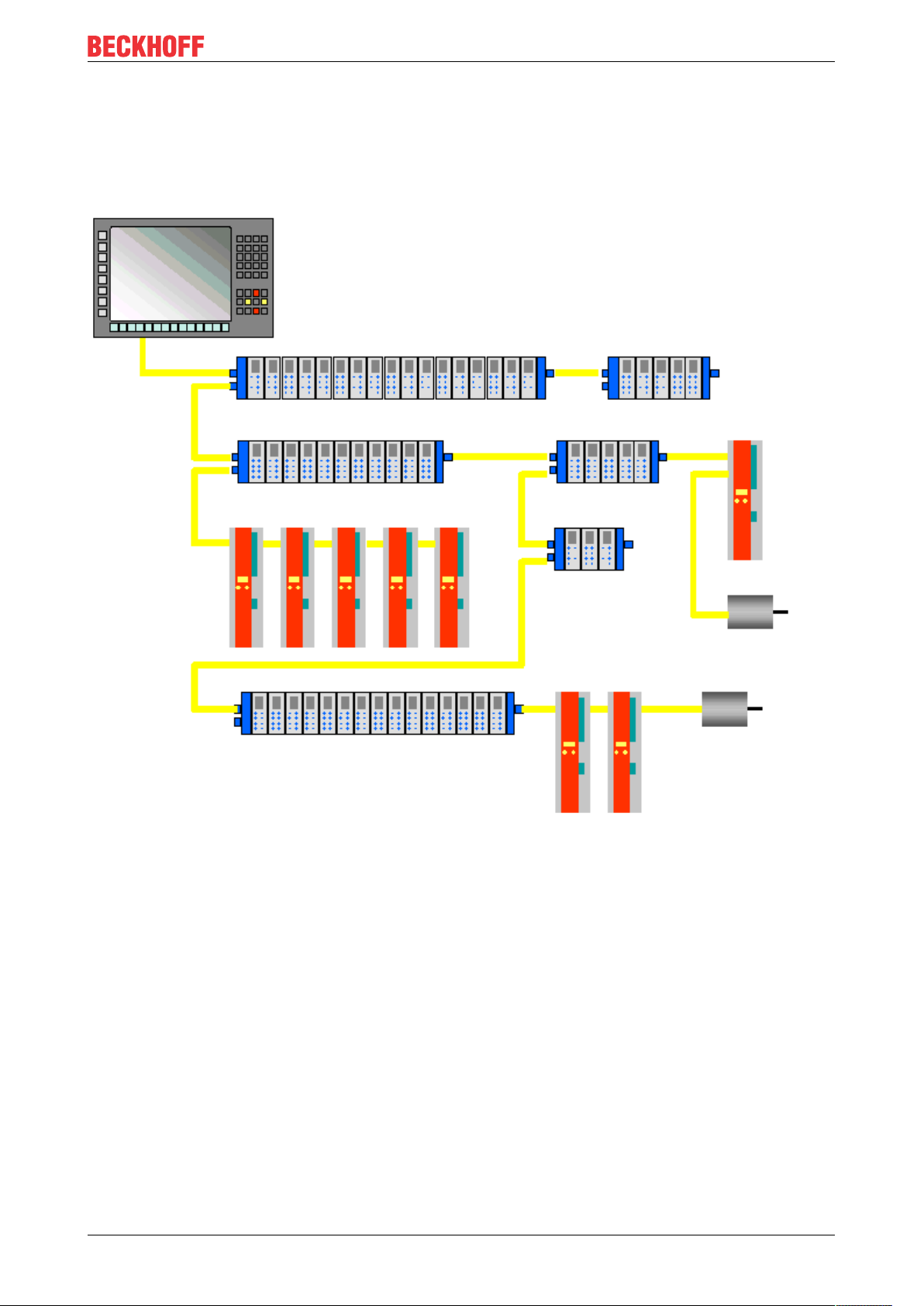
Topology
Line, tree or star: EtherCAT supports almost any topology. The bus or line structure known from the
fieldbusses thus also becomes available for Ethernet. Particularly useful for system wiring is the combination
of line and branches or stubs. The required interfaces exist on the couplers; no additional switches are
required. Naturally, the classic switch-based Ethernet star topology can also be used.
Maximum wiring flexibility:
with or without switch, line or tree topologies, can be freely selected and combined. The complete bandwidth
of the Ethernet network - such as different optical fibers and copper cables - can be used in combination with
switches or media converters.
Distributed Clocks
Accurate synchronization is particularly important in cases where spatially distributed processes require
simultaneous actions. This may be the case, for example, in applications where several servo axes carry out
coordinated movements simultaneously.
The most powerful approach for synchronization is the accurate alignment of distributed clocks, as described
in the new IEEE 1588 standard. In contrast to fully synchronous communication, where synchronization
quality suffers immediately in the event of a communication fault, distributed aligned clocks have a high
degree of tolerance vis-à-vis possible fault-related delays within the communication system.
With EtherCAT, the data exchange is fully based on a pure hardware machine. Since the communication
utilizes a logical (and thanks to full-duplex Fast Ethernet also physical) ring structure, the mother clock can
determine the run-time offset to the individual daughter clocks simply and accurately - and vice versa. The
distributed clocks are adjusted based on this value, which means that a very precise network-wide timebase
with a jitter of significantly less then 1 microsecond is available.
IL230x-B110 9Version: 1.0.3
Page 10

Basics
However, high-resolution distributed clocks are not only used for synchronization, but can also provide
accurate information about the local timing of the data acquisition. For example, controls frequently calculate
velocities from sequentially measured positions. Particularly with very short sampling times, even a small
temporal jitter in the displacement measurement leads to large step changes in velocity. With EtherCAT new,
extended data types are introduced as a logical extension (time stamp and oversampling data type). The
local time is linked to the measured value with a resolution of up to 10 ns, which is made possible by the
large bandwidth offered by Ethernet. The accuracy of a velocity calculation then no longer depends on the
jitter of the communication system. It is orders of magnitude better than that of measuring techniques based
on jitter-free communication.
Performance
EtherCAT reaches new dimensions in network performance. Protocol processing is purely hardware-based
through an FMMU chip in the terminal and DMA access to the network card of the master. It is thus
independent of protocol stack run-times, CPU performance and software implementation. The update time
for 1000 I/Os is only 30 µs - including terminal cycle time. Up to 1486 bytes of process data can be
exchanged with a single Ethernet frame - this is equivalent to almost 12000 digital inputs and outputs. The
transfer of this data quantity only takes 300 µs.
The communication with 100 servo axes only takes 100 µs. During this time, all axes are provided with set
values and control data and report their actual position and status. Distributed clocks enable the axes to be
synchronised with a deviation of significantly less than 1 microsecond.
The extremely high performance of the EtherCAT technology enables control concepts that could not be
realized with classic fieldbus systems. For example, the Ethernet system can now not only deal with velocity
control, but also with the current control of distributed drives. The tremendous bandwidth enables status
information to be transferred with each data item. With EtherCAT, a communication technology is available
that matches the superior computing capacity of modern Industrial PCs. The bus system is no longer the
bottleneck of the control concept. Distributed I/Os are recorded faster than is possible with most local I/O
interfaces. The EtherCAT technology principle is scalable and not bound to the baud rate of 100 MBaud –
extension to GBit Ethernet is possible.
Diagnostics
Experience with fieldbus systems shows that availability and commissioning times crucially depend on the
diagnostic capability. Only faults that are detected quickly and accurately and which can be precisely located
can be corrected quickly. Therefore, special attention was paid to exemplary diagnostic features during the
development of EtherCAT.
During commissioning, the actual configuration of the I/O terminals should be checked for consistency with
the specified configuration. The topology should also match the saved configuration. Due to the built-in
topology recognition down to the individual terminals, this verification can not only take place during system
start-up, automatic reading in of the network is also possible (configuration upload).
Bit faults during the transfer are reliably detected through evaluation of the CRC checksum: The 32 bit CRC
polynomial has a minimum hamming distance of 4. Apart from breaking point detection and localization, the
protocol, physical transfer behavior and topology of the EtherCAT system enable individual quality
monitoring of each individual transmission segment. The automatic evaluation of the associated error
counters enables precise localization of critical network sections. Gradual or changing sources of error such
as EMC influences, defective push-in connectors or cable damage are detected and located, even if they do
not yet overstrain the self-healing capacity of the network.
Integration of standard Bus Terminals from Beckhoff
In addition to the new Bus Terminals with E-Bus connection (ELxxxx), all Bus Terminals from the familiar
standard range with K-Bus connection (KLxxxx) can be connected via the BK1120 or BK1250 Bus Coupler.
This ensures compatibility and continuity with the existing Beckhoff Bus Terminal systems. Existing
investments are protected.
IL230x-B11010 Version: 1.0.3
Page 11
Basics
2.2 CoE Interface
Object directory
All EtherCAT slaves supporting the CoE interface have an object directory containing all parameter,
diagnostic, process or other data that can be read or written via EtherCAT.
The object directory can be read via the SDO information service. It is included in the device description file.
All EtherCAT slaves should support the SDO information service at least to such an extent that the compact
object description of each object can be read (from index 0x1000). This object description contains the data
type, the length, the access rights and information as to whether the object can be mapped in a PDO (and
therefore can be used as process data).
Start-Up list
The Start-up list describes the interrelationship between EtherCAT state machine, process data mapping
and device parameter settings during start-up of EtherCAT network.
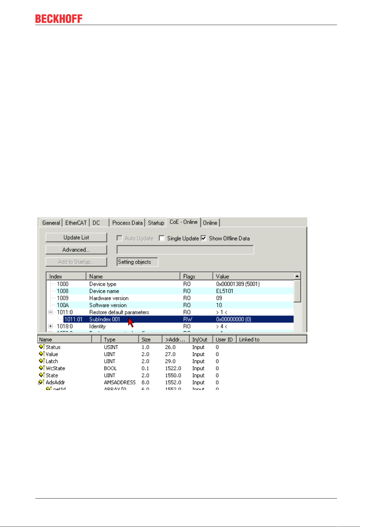
Restoring the delivery state
Restoring the delivery state To restore the delivery state for backup objects in ELxxxx terminals, the CoE
object "Restore default parameters", SubIndex001 can be selected in the TwinCAT System Manager
(Config mode) (see Fig. 1)
Fig. 1 Selecting the "Restore default parameters" PDO
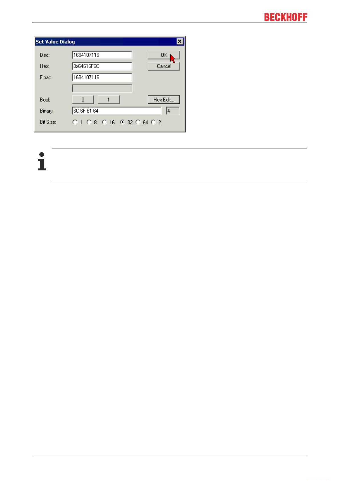
Double-click on SubIndex 001 to enter the Set Value dialog. Enter the value 1684107116 in field "Dec" or the
value 0x64616F6C in field "Hex" and confirm with OK (Fig. 2).
All backup objects are reset to the delivery state.
IL230x-B110 11Version: 1.0.3
Page 12
Basics
Fig. 2 Entering a restore value in the Set Value dialog
Alternative restore value
In some older terminals the backup objects can be switched with an alternative restore value: Decimal value: "1819238756" Hexadecimal value: "0x6C6F6164" An incorrect entry for the restore value
has no effect.
IL230x-B11012 Version: 1.0.3
Page 13
Basics
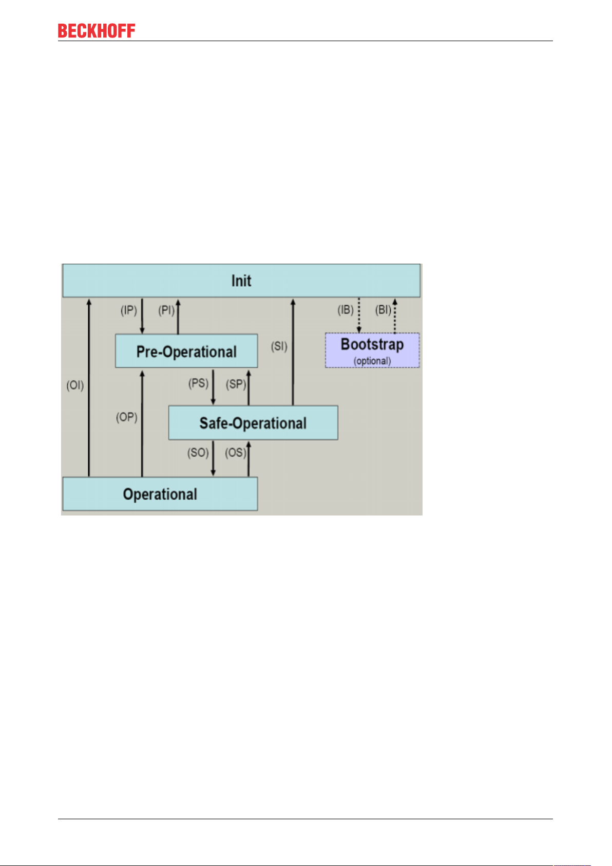
2.3 EtherCAT State Machine
The state of the EtherCAT slave is controlled via the EtherCAT State Machine (ESM). Depending upon the
state, different functions are accessible or executable in the EtherCAT slave. Specific commands must be
sent by the EtherCAT master to the device in each state, particularly during the bootup of the slave.
A distinction is made between the following states:
• Init
• Pre-Operational
• Safe-Operational and
• Operational
• Boot
The regular state of each EtherCAT slave after bootup is the OP state.
Init
After switch-on the EtherCAT slave in the Init state. No mailbox or process data communication is possible.
The EtherCAT master initializes sync manager channels 0 and 1 for mailbox communication.
Pre-Operational (Pre-Op)
During the transition between Init and Pre-Op the EtherCAT slave checks whether the mailbox was initialized
correctly.
In Pre-Op state mailbox communication is possible, but not process data communication. The EtherCAT
master initializes the sync manager channels for process data (from sync manager channel 2), the FMMU
channels and, if the slave supports configurable mapping, PDO mapping or the sync manager PDO
assignment. In this state the settings for the process data transfer and perhaps terminal-specific parameters
that may differ from the default settings are also transferred.
Safe-Operational (Safe-Op)
During transition between Pre-Op and Safe-Op the EtherCAT slave checks whether the sync manager
channels for process data communication and, if required, the distributed clocks settings are correct. Before
it acknowledges the change of state, the EtherCAT slave copies current input data into the associated DPRAM areas of the EtherCAT slave controller (ECSC).
IL230x-B110 13Version: 1.0.3
Page 14

Basics
In Safe-Op state mailbox and process data communication is possible, although the slave keeps its outputs
in a safe state, while the input data are updated cyclically.
Outputs in SAFEOP state
The default set watchdog monitoringremoved link: watchdog monitoring sets the outputs of the
module in a safe state - depending on the settings in SAFEOP and OP - e.g. in OFF state. If this is
prevented by deactivation of the watchdog monitoring in the module, the outputs can be switched or
set also in the SAFEOP state.
Operational (Op)
Before the EtherCAT master switches the EtherCAT slave from Safe-Op to Op it must transfer valid output
data.
In the Op state the slave copies the output data of the masters to its outputs. Process data and mailbox
communication is possible.
Boot
In the Boot state the slave firmware can be updated. The Boot state can only be reached via the Init state.
In the Boot state mailbox communication via the file access over EtherCAT (FoE) protocol is possible, but no
other mailbox communication and no process data communication.
IL230x-B11014 Version: 1.0.3
Page 15

Product overview
3 Product overview
3.1 The Fieldbus Box System
Fieldbus box modules are robust fieldbus stations for a large number of different fieldbus systems. They offer
a wide range of I/O functionality. All relevant industrial signals are supported. As well as digital and analog
inputs and outputs including thermocouple and RTD inputs, there are also incremental encoder interfaces
available for displacement and angle measurement as well as serial interfaces to solve a large number of
communications tasks.
Three varieties of signal connection
The digital inputs and outputs can be connected with snap-on 8mm diameter plugs, screw-in M8
connectors, or with screw-in M12 pendants. The M12 version is provided for analog signals.
All important signal types
Special input and output channels on the combination I/O modules can be used for either input or output. It is
not necessary to configure them, since the fieldbus interface is available for every combination channel as
well as for input and output data. The combination modules give the user all of the advantages of fine signal
granularity.
The processor logic, the input circuitry and the power supply for the sensor are all fed from the control
voltage. The load voltage for the outputs can be supplied separately. In those Fieldbus Boxes in which only
inputs are available, the load power supply, UP, can optionally be connected in order to pass it on
downstream.
The states of the Fieldbus Box, the fieldbus connection, the power supplies and of the signals are indicated
by LEDs.
The label strips can be machine printed elsewhere, and then inserted.
Fieldbus Boxes can be combined for greater flexibility
In addition to the Compact Box, the Fieldbus Box series also includes extendable devices, namely the
Coupler Box and the Extension Box, as well as intelligent devices, the PLC Boxes.
Compact Box
The Compact Box makes the I/O data from the connected digital and analog sensors and actuators available
to the fieldbus.
Coupler Box
The Coupler Box also collects I/O data from the Extension Boxes via an interference-proof optical fiber
connection (IP-Link). Up to 120 Extension Boxes can be connected to a Coupler Box. In this way a
distributed IP67 I/O network is formed with only one fieldbus interface.
The Coupler Box is capable of automatically recognizing the extension modules connected to it during startup, and maps the I/O data automatically into the fieldbus process image – a configuration is not necessary.
The Coupler Box appears, from the fieldbus point of view, along with all of the networked Extension Boxes,
as a single participating bus device with a corresponding number of I/O signals.
The Coupler Box corresponds to the Bus Coupler in the BECKHOFF Bus Terminal system. BECKHOFF
fieldbus devices made to protection class IP 20 (Bus Terminals) and IP 67 (Fieldbus Box) can be combined
without difficulty – the data is handled in the same way in either case.
IL230x-B110 15Version: 1.0.3
Page 16

Product overview
IP-Link
The IP-Link is an optical fiber connection with a transmission rate of 2 MBits/s which is capable of
transmitting 1000 items of binary I/O data in approx. 1 ms, rapidly and securely. Smaller configurations are
correspondingly faster. Because of the high usable data rate, the coupling via IP-Link does not reduce the
performance of the fieldbus at all.
Low-priced plug connectors made according to Protection Class IP67 can be used for the rapid and simple
preparation of the IP-Link cable, in situ. The connection does not require special tools, and can be performed
quickly and simply. The IP-Link cables can also be obtained with prepared plugs if required.
The separate supply of the output voltage allows output groups to be switched off individually. Differing
potentials can also be created within an extension ring without difficulty, since the IP-Link naturally has
optimum electrical isolation.
Extension box
Like the Compact Boxes, the Extension Boxes cover the full spectrum of I/O signals, and may be up to 15m
apart. They are remarkably small in size, and lead to particularly economical I/O solutions with high levels of
protection. Here again, the digital inputs and outputs may optionally be connected via snap-on 8 mm
connectors, or via screw-in connectors (M8 and M12). Analog signal types are provided with the M12
version. The snap-on connectors lock in place positively, forming a shake-proof connection, while the screwin connectors offer the advantage of high resistance to being pulled out.
PLC Box
The PLC Box is an intelligent Fieldbus Box with PLC functionality for distributed pre-processing of the I/O
signals. This allows parts of the application to be farmed out from the central controller. This reduces the
load on the CPU and the fieldbus. Distributed counting, controlling and switching are typical applications for
the PLC Box. The reaction times are independent of the bus communication and of the higher-level
controller.
In the event of a bus or controller failure, maintenance of function (e.g. bringing the process to a safe state in
an orderly manner) is possible.
Programming is carried out with TwinCAT in accordance with IEC 61131-3. Five different programming
languages are available:
• Instruction List (IL)
• Function Block Diagram (FBD)
• Ladder Diagram (LD)
• Sequential Function Chart (SFC)
• Structured Text (ST)
The program download occurs either via the fieldbus or via the programming interface.
Extensive debugging functions (breakpoint, single step, monitoring, etc) are also available. The PLC Box
contains a powerful 16 bit controller, 32/96 kByte program memory and 32/64 kByte data memory. A further
512 bytes of non-volatile memory are available for remanent flags.
PLC Box with IP-Link
The programmable PLC Box with IP-Link provides almost unlimited I/O possibilities. Up to 120 extension
modules, with more than 2000 I/Os, can be directly addressed from the PLC program. The PLC Box is thus
also suitable for use as a small, autonomous controller for the operation of parts of equipment or small
machines.
IL230x-B11016 Version: 1.0.3
Page 17

3.2 Fieldbus Box - Naming conventions
The identifications of the Fieldbus Box modules are to be understood as follows:
IXxxxy-zyyy
IX describes the design:
"IP" stands for the CompactBox design [}18]
"IL" stands for the CouplerBox design (with IP-Link) [}18]
"IE" stands for the ExtensionBox design [}18]
xxxy describes the I/O connection:
xxx describes the I/O property:
"10x" - 8 x digital inputs
"15x" - counter module
"20x" - 8 x digital outputs
"25x" - PWM module
"23x" - 4 x digital inputs and 4 x digital outputs
"24x" - 8 x digital inputs and 8 x digital outputs
"3xx" - 4 x analog inputs
"4xx" - 4 x analog outputs
"5xx" - incremental encoder or SSI transducer
"6xx" - Gateway module for RS232, RS422, RS485, TTY
Product overview
y represents the mechanical connection:
"0" stands for 8mm snap-on connection,
"1" stands for M8 bolted connection
"2" stands for M12 bolted connection and
"9" stands for M23 bolted connection
zyyy describes the programmability and the fieldbus system
z distinguishes whether the device is a slave or is a programmable slave:
"B" - not programmable
"C" - programmable (PLC Box)
"yyy" stands for the fieldbus system and the bus connection:
"110" - EtherCAT
"200" - Lightbus
"310" - PROFIBUS
"318" - PROFIBUS with integrated tee-connector
"400" - Interbus
"510" - CANopen
"518" - CANopen with integrated tee-connector
"520" - DeviceNet
"528" - DeviceNet with integrated tee-connector
"730" - Modbus
"800" - RS485
"810" - RS232
"900" - Ethernet TCP/IP with RJ45 for the bus connection
"901" - Ethernet TCP/IP with M12 for the bus connection
"903" - PROFINET
"905" - EtherNet/IP
IL230x-B110 17Version: 1.0.3
Page 18

Product overview
Compact Box
Compact Box
The Compact Box modules offer a wide range of I/O functionality. All relevant industrial signals are
supported. The digital inputs and outputs can be connected either with snap-on 8mm diameter plugs, screwin M8 connectors, or screw-in M12 connectors. The M12 version is made available for analog signals.
Depending on the module, the I/O section and the power supply section can differ.
Coupler Box
Coupler Box
There are three versions of the coupler box named IL230x-Bxxx. It differs from the compact box in that this
module offers an interface to what are known as extension boxes. This interface is a subsidiary bus system
based on the optical fiber what is known as IPLink. This powerful subsidiary bus system can handle up to
120 extension boxes at one coupler box.
Extension Box
Extension Box
Extension Modules, that are independent of the fieldbus and that can only be operated together with a
coupler box via IPLink.
PLC Box
PLC Box
A PLC Box differ from the Coupler Box in that this module can be programmed in IEC 61131-3. This means
that this slave is also capable of working autonomously, without a master, for instance for control or
regulation tasks.
Also see about this
2 Fieldbus Box - Naming conventions [}18]
IL230x-B11018 Version: 1.0.3
Page 19

Product overview
3.3 Firmware and hardware issue status
The documentation refers to the hardware and software status that was valid at the time it was prepared.
The properties are subject to continuous development and improvement. Modules having earlier production
statuses cannot have the same properties as modules with the latest status. Existing properties, however,
are always retained and are not changed, so that these modules can always be replaced by new ones.
The number beginning with a D allows you to recognize the firmware and hardware status of a module.
Syntax:
D.wwyyxyzu
ww - calendar week
yy - year
x - bus board firmware status
y - bus board hardware status
z - I/O board firmware status
u - I/O board hardware status
Example:
D.22081501
- Calendar week 22
- in the year 2008
- bus board firmware status: 1
- bus board firmware hardware status: 5
- I/O board firmware status: 0 (no firmware is necessary for this board)
- I/O board hardware status: 1
IL230x-B110 19Version: 1.0.3
Page 20

Product overview
3.4 Technical data
Technical data IL230x-B110
Extension modules (IL....) max. 32 (until firmware version B0)
max. 78 (from firmware version B1)
Number of bytes, fieldbus max. 512bytes Input and max. 512bytes output
Digital peripheral signals (IL....) max. 624inputs and max. 624outputs
Analog peripheral signals (IL....) max. 128inputs and max. 128outputs
Data transfer medium 4 x 2 twisted pair copper cable; category 5 (100
Mbaud)
Baud rate 100 Mbaud
Distance between modules 100 m
Configuration KS2000 configuration software, TwinCAT System
Manager or via EtherCAT (ADS)
Protocols EtherCAT (Direct Mode)
Power supply Control voltage: 24VDC (-15%/+20%); load voltage:
According to I/O type
Control voltage current consumption According to I/O type + current consumption of
sensors, max. 0.5 A
Load voltage current consumption According to I/O type
Power supply connection Feed: 1 x M8 plug, 4-pin
Onward connection: 1 x M8 socket, 4-pin (except IP/
IE204x)
Fieldbus connection 2 x M12 d-coded, socket
Electrical isolation Channels/control voltage: no
between the channels: no
Control voltage/fieldbus: yes
Operating temperature 0°C... +55°C
Storage temperature -25°C... +85°C
Vibration / shock resistance conforms to EN60068-2-6/ EN60068-2-27,
EN60068-2-29
EMC resistance burst / ESD conforms to EN61000-6-2 (EN50082)/
EN61000-6-4 (EN50081)
Protection class IP 65/66/67 (conforms to EN 60529)
Installation position any
Approvals CE, UL E172151
Further documentation
Detailed technical data for all available I/O variants can be found under Signal variants, Installation,
I/O module configuration on Products & Solutions CD from Beckhoff or on the Internet (http://
www.beckhoff.com) under Download/Fieldbus Box.
IL230x-B11020 Version: 1.0.3
Page 21
4 Mounting and wiring
4.1 Dimensions
Mounting and wiring
All dimensions are given in millimeters.
General
Technical data Fieldbus Box
Material PA6 (polyamide), casting compound: polyurethane
Assembly 2 x fixing holes for M3
Metal parts Brass, nickel-plated
Contacts CuZn, gold-plated
Vibration / shock resistance according to EN60068-2-6/ EN60068-2-27,
EN60068-2-29
EMC resistance burst / ESD according to EN61000-6-2 (EN50082)/
EN61000-6-4 (EN50081)
Permissible ambient temperature during operation 0... 55°C
Permissible ambient temperature during storage -25 ... + 85°C
Installation position any
Type of protection IP65/66/67 when screwed together
Approvals CE, UL E172151
IL230x-B110 21Version: 1.0.3
Page 22

Mounting and wiring
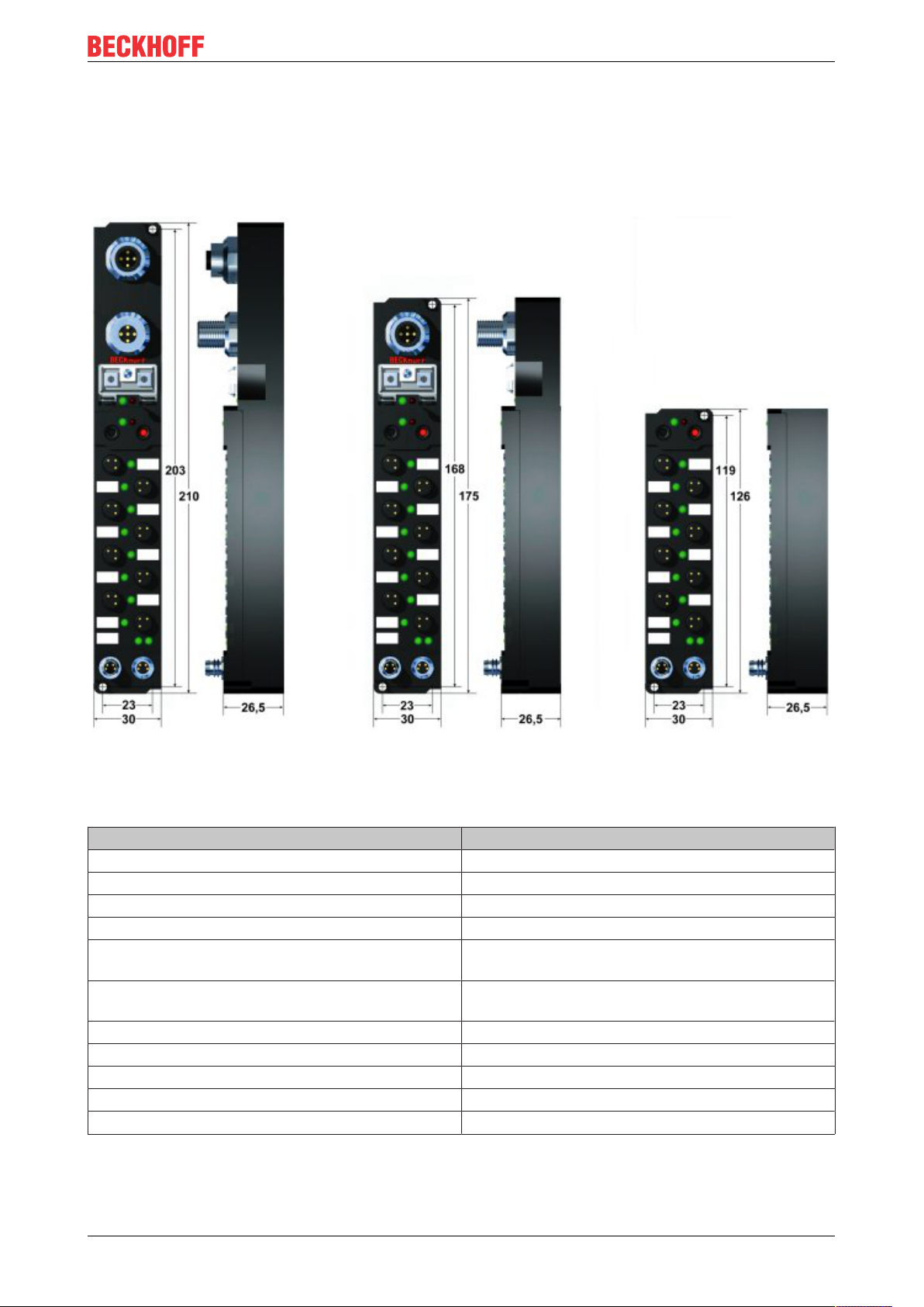
IPxxxx-Bxx8, IL230x-Bxx8, IL230x-B110, IXxxxx-B400, IXxxxx-B90x, IXxxxx-C900
Technical data Compact and Coupler Box with integrated tee
connector
Dimensions (Hx WxD) ca. 210 x30x26,5mm (height to upper edge of
fieldbus socket: 30 mm)
Weight ca. 260g-290g, depending on module type
IPxxxx-Bxx0, IL230x-Bxx0, IL230x-Cxx0
Technical data Compact and Coupler Box
Dimensions (Hx WxD) Approx. 175 x 30 x 26.5 mm (height to upper edge of
fieldbus socket: 30 mm, with T- connector
ZS1031-2600 height approx. 65 mm)
Weight Approx. 250 g - 280 g, depending on module type
IExxxx
Technical data Extension box
Dimensions (Hx WxD) Approx. 126 x 30 x 26.5 mm
Weight Approx. 120 g - 200 g, depending on module type
IL230x-B11022 Version: 1.0.3
Page 23

Mounting and wiring
4.2 EtherCAT connection
The EtherCAT connection is established via two d-coded M12 sockets (one for the EtherCAT input, one for
the output).
The cable length between two EtherCAT devices must not exceed 100 m.
Cables and connectors
For connecting EtherCAT devices only Ethernet cables that meet the requirements of at least category 5
(CAt5) according to EN 50173 or ISO/IEC 11801 should be used. EtherCAT uses 4 wires for signal transfer.
The following cables and connectors are suitable for application in EtherCAT systems:
Name Comment
ZB9010 EtherCAT cable, fixed installation, CAT 5e, 4-core
ZB9020 EtherCAT cable, suitable for drag chain applications
CAT 5e, 4-core
ZS1090-0004 M12 connector, 4-pin, IP67, field-configurable
ZK1090-6161-0005 EtherCAT cable, ready-made, M12 connector - M12
connector, 0.5 m length
ZK1090-6161-0010 EtherCAT cable, ready-made, M12 connector - M12
connector, 1.0m length
ZK1090-6161-0020 EtherCAT cable, ready-made, M12 connector - M12
connector, 2.0m length
ZK1090-6161-0025 EtherCAT cable, ready-made, M12 connector - M12
connector, 2.5m length
ZK1090-6161-0050 EtherCAT cable, ready-made, M12 connector - M12
connector, 5.0m length
ZK1090-6161-0100 EtherCAT cable, ready-made, M12 connector - M12
connector, 10m length
ZK1090-6292-0005 EtherCAT cable, female M12 connector - RJ45, 0.5
m length
ZK1090-6292-0020 EtherCAT cable, female M12 connector - RJ45, 2.0
m length
Data sheets
There are different standards for assignment and colors at plugs and cables for Ethernet/EtherCAT.
Please take assignment and colors of Beckhoff cables from the according data sheets.
Pin assignment of the M12 plug (d-coded)
IL230x-B110 23Version: 1.0.3
Page 24

Mounting and wiring
PIN Signal Description
1 Tx + Transmit Data+
2 Rx + Receive Data+
3 Tx- Transmit Data4 Rx- Receive Data-
Pin assignment of the RJ45 plug
PIN Signal Description
1 TD + Transmit Data+
2 TD - Transmit Data3 RD + Receive Data+
4 - reserved
5 - reserved
6 RD - Receive Data7 - reserved
8 - reserved
IL230x-B11024 Version: 1.0.3
Page 25
Parameterizning and commissioning
5 Parameterizning and commissioning
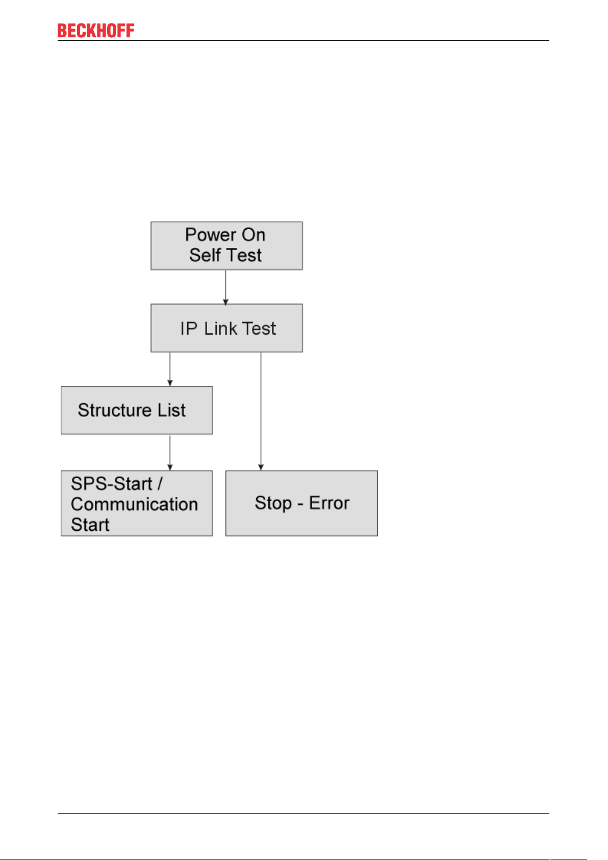
5.1 Start-up behavior of the Fieldbus Box
After power up, the Fieldbus Box checks its state, configures the IP-Link (if present) and refers to the
extension modules to create a structure list. If the Fieldbus Box contains a decentralized controller (IL230xC310) the local PLC is started once the structure list has successfully been created.
The I/O LEDs illuminate and flash as the module starts up. If there are no errors, the I/O LEDs should stop
flashing within about 2-3 seconds. If there is an error, then the LED that flashes will depend on the type of
that error (see Diagnostic LEDs).
IL230x-B110 25Version: 1.0.3
Page 26

Configuration
6 Configuration
6.1 TwinCAT System Manager
6.1.1 Configuration overview
IL230x-B110 [}26] Inputs [}27] Outputs [}28] Working counter status (WcState) [}29] Online status
(Info Data) [}30] ADS address (ADSAddr) [}31] EtherCAT cycle time [}32]
IL230x-B110 (IL2300-B110, IL2301-B110, IL2302-B110)
IL230x-B110 (IL2300-B110, IL2301-B110, IL2302-B110)
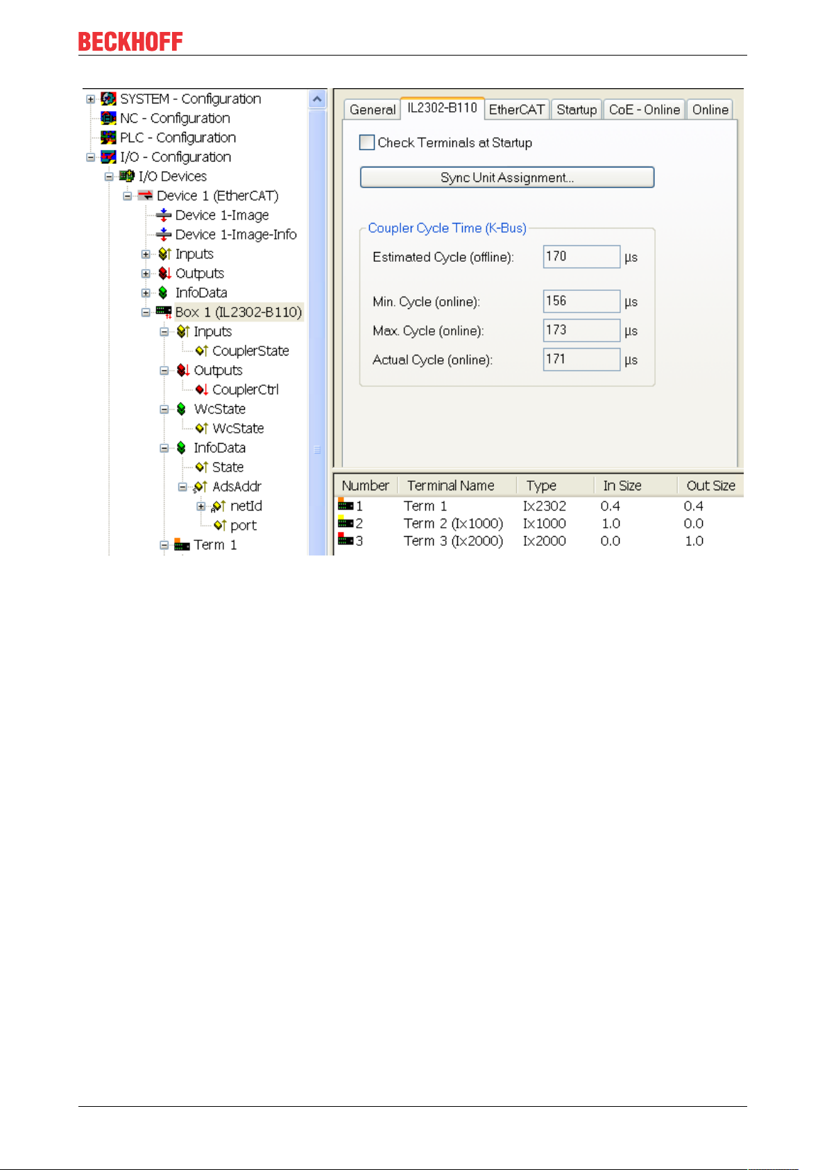
In TwinCAT System Manager Config mode enter the IL230x-B110 as an EtherCAT (Direct Mode) device
under Devices (Fig. 1). Any Fieldbus Box modules already connected to the network can also be read. All
boxes with extensions and configurations are uploaded automatically. You can then adapt these to meet
your requirements. FreeRun status must be set in TwinCAT.
Note regarding the screenshots: IP-Link values are displayed as K-Bus values in TwinCAT.
IL230x-B11026 Version: 1.0.3
Page 27

Configuration
Fig.1: Fbb_B110_TCAT_Sysman1
Fig. 1 TwinCAT tree IL2302-B110
Inputs
Inputs
CouplerState, "Online" tab
Display of general Fieldbus Box errors.
IL230x-B110 27Version: 1.0.3
Page 28

Configuration
Fig. 3 CouplerState, "Online" tab
Outputs
Outputs
CouplerCtrl, "Online" tab
Display of IP-Link/K-Bus errors or deactivation of outputs.
IL230x-B11028 Version: 1.0.3
Page 29

Configuration
Fig. 4 CouplerCrtl, "Online" tab
Working counter status (WcState)
Working counter status (WcState)
WCstate, "Online" tab
Boolean variable indicating the working counter status of the Fieldbus Box. An invalid working counter
(value: 1) is displayed if invalid data were transferred by the EtherCAT slave controller.
IL230x-B110 29Version: 1.0.3
Page 30

Configuration
Fig. 5 WCstate, "Online" tab
Online status (Info Data)
Online status (Info Data)
State, "Online" tab
Indicates the online status of the Fieldbus Box.
IL230x-B11030 Version: 1.0.3
Page 31

Configuration
Fig. 6 State, "Online" tab
Value Description
0x___1 Slave in 'INIT' state
0x___2 Slave in 'PREOP' state
0x___3 Slave in 'BOOT' state
0x___4 Slave in 'SAFEOP' state
0x___8 Slave in 'OP' state
0x001_ Slave signals error
0x002_ Invalid vendorId, productCode... read
0x004_ Initialization error occurred
0x010_ Slave not present
0x020_ Slave signals link error
0x040_ Slave signals missing link
0x080_ Slave signals unexpected link
0x100_ Communication port A
0x200_ Communication port B
0x400_ Communication port C
0x800_ Communication port D
ADS address (ADSAddr)
ADS address (ADSAddr)
IL230x-B110 31Version: 1.0.3
Page 32
Configuration
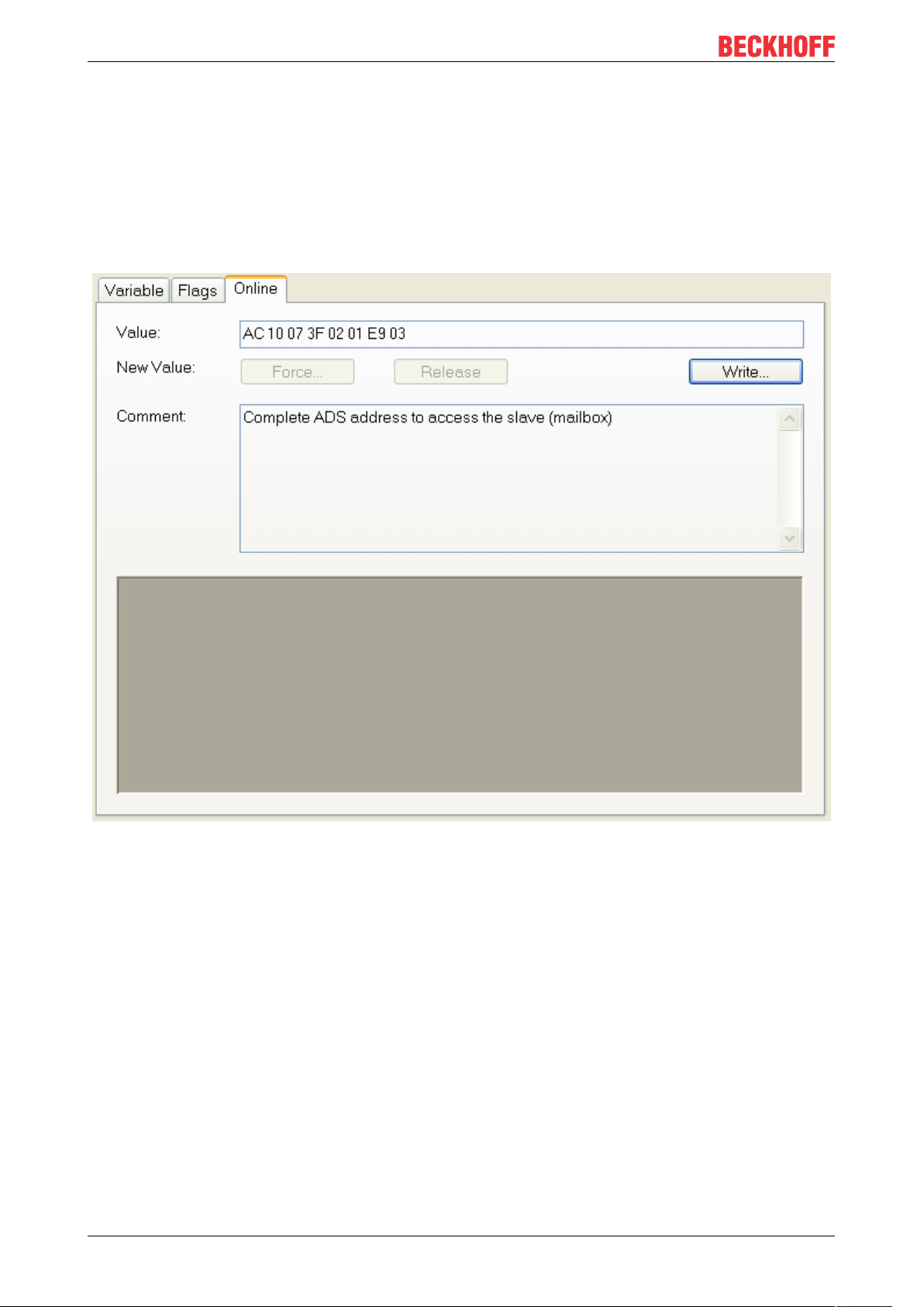
ADSAddr, Online tab
Single line indicating the AMS netID and the AMS port of the Fieldbus Box using the hexadecimal system.
This information is required for mailbox communication via ADS.
Example
AC 10 07 3F 02 01 (AMS netID) = 172.16.7.63.2.1
03 E9 (port) = 1001
dec
Fig. 7 ADSAddr, "Online" tab
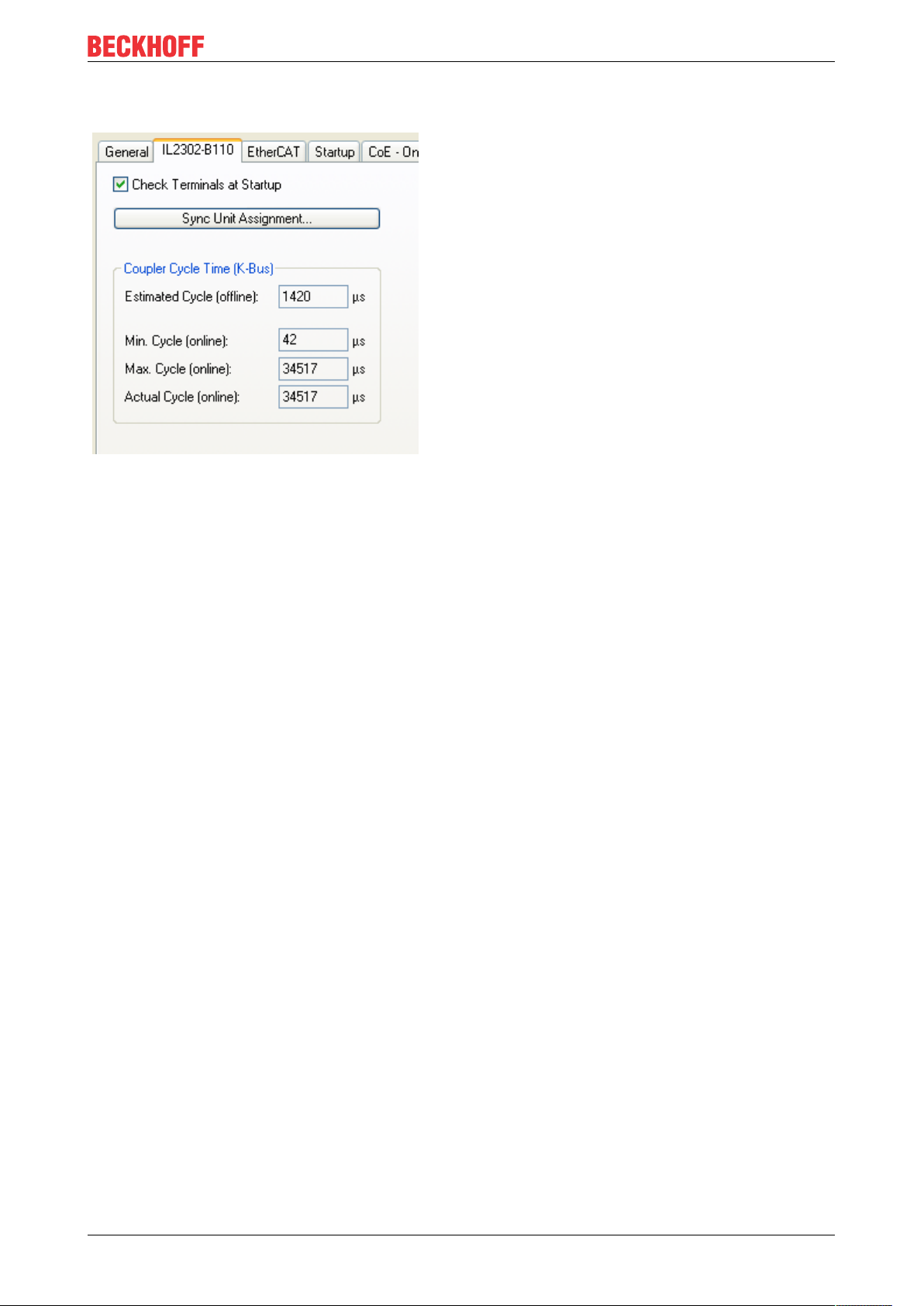
EtherCAT / IP-Link cycle time
EtherCAT / IP-Link cycle time
The IP-Link cycle time resulting from the station configuration with extension box modules is directly
displayed in ConfigMode.
IL230x-B11032 Version: 1.0.3
Page 33
Configuration
Fig. 8 CycleTime
If the EtherCAT cycle time exceeds the IP-Link cycle time both systems operate in synchronous mode. The
IP link is started after an EtherCAT telegram and copies its inputs into the memory. They are retrieved with
the next EtherCAT telegram, i.e. the inputs are always exactly one cycle old.
If the EtherCAT cycle is shorter than the IP link cycle, the K-Bus operates asynchronous relative to
EtherCAT. Faster polling than "Estimated Cycle (offline)" is therefore possible but may lead to outdated input
data or outputs not being set in time via the IP link.
The EtherCAT cycle applied to the IL230x-B110 Fieldbus Box modules should therefore be significantly
greater than the "Estimated Cycle (offline)" (min. 250 µs, depending on the configuration). Online control in
the system through "Max. Cycle (online)" or "CouplerState" is recommended.
The cycle time can also be read via CoE Online from Table 98 [LO].
IL230x-B110 33Version: 1.0.3
Page 34
Configuration
Fig. 9 CycleTime via Table98[LO]
IL230x-B11034 Version: 1.0.3
Page 35
Configuration
Check of the connected boxes
If you activate "Check Terminals at Startup", at startup is checked if the connected boxes fit to the configured
boxes.
IL230x-B110 35Version: 1.0.3
Page 36

Configuration
6.2 Objects
6.2.1 Object description
Table1: Extracted nested table 0
IL230x-B11036 Version: 1.0.3
Page 37

Index Name Meaning
6000:0 IE23xx IE2301, max .
Subindex (4)
6000:01 Channel 1 1. Channel, IE2301
6000:02 Channel 2 2. Channel, IE2301
6000:03 Channel 3 3. Channel, IE2301
6000:04 Channel 4 4. Channel, IE2301
6010:0 IE10xx IE1001, max.
Subindex (8)
6010:01 Channel 1 1. Channel, IE1001
6010:02 Channel 2 2. Channel, IE1001
6010:03 Channel 3 3. Channel, IE1001
6010:04 Channel 4 4. Channel, IE1001
6010:05 Channel 5 5. Channel, IE1001
6010:06 Channel 6 6. Channel, IE1001
6010:07 Channel 7 7. Channel, IE1001
6010:08 Channel 8 8. Channel, IE1001
6030:0 IE3102 IE3102, max.
Subindex (12)
6030:01 Channel 1 Status 1. Channel, Status,
IE3102
6030:03 Channel 1 Data 1. Channel, Data
IE3102
6030:04 Channel 2 Status 2. Channel, Status,
IE3102
6030:06 Channel 2 Data 2. Channel, Data,
IE3102
6030:07 Channel 3 Status 3. Channel, Status,
IE3102
6030:09 Channel 3 Data 3. Channel, Data,
IE3102
6030:0A Channel 4 Status 4. Channel, Status,
IE3102
6030:0C Channel 4 Data 4. Channel, Status,
IE3102
Signals in Coupler
Box: IE2301
Position 1 behind
Coupler Box:
IE1001
Position 3 behind
Coupler Box:
IE3102
Configuration
Input data
IL230x-B110 37Version: 1.0.3
Page 38

Configuration
Index Name Meaning
7000:0 IE23xx IE2301, max .
Subindex (4)
7000:01 Channel 1 1. Channel, IE2301
7000:02 Channel 2 2. Channel, IE2301
7000:03 Channel 3 3. Channel, IE2301
7000:04 Channel 4 4. Channel, IE2301
7020:0 IE20xx IE2001, max .
Subindex (8)
7020:01 Channel 1 1. Channel, IE2001
7020:02 Channel 2 2. Channel, IE2001
7020:03 Channel 3 3. Channel, IE2001
7020:04 Channel 4 4. Channel, IE2001
7020:05 Channel 5 5. Channel, IE2001
7020:06 Channel 6 6. Channel, IE2001
7020:07 Channel 7 7. Channel, IE2001
7020:08 Channel 8 8. Channel, IE2001
7030:0 IE3102 IE3102, max.
Subindex (12)
7030:01 Channel 1 Control 1. Channel,
Control, IE3102
7030:03 Channel 1 Data 1. Channel, Data
IE3102
7030:04 Channel 2Control 2. Channel,
Control, IE3102
7030:06 Channel 2 Data 2. Channel, Data
IE3102
7030:07 Channel 3 Control 3. Channel,
Control, IE3102
7030:09 Channel 3 Data 3. Channel, Data
IE3102
7030:0A Channel 4 Control 4. Channel,
Control, IE3102
7030:0C Channel 4Data 4. Channel, Data
IE3102
Signals in Coupler
Box: IE2301
Position 2 behind
Coupler Box:
IE3102
Position 3 behind
Coupler Box:
IE3102
Output data
Standard objects
Standard objects
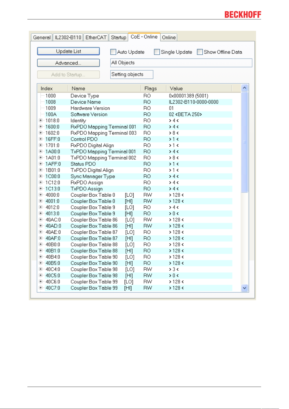
Index 1000 Device type
Index 1000
Device type (read only) of the EtherCAT slave.
Index Name Meaning Flags Default
1000 DeviceType Device type RO 0x00001389
(5001
dec
)
Index 1008 Device name
Index 1008
Device name (read only, Value: z. B. IL2302-B110-0000-0000) of the EtherCAT slave.
IL230x-B11038 Version: 1.0.3
Page 39

Configuration
Index Name Meaning Flags Default
1008 DeviceName Device name RO e.g. IL2302-
B110-0000-0000
Index 1009 Hardware version
Index 1009
Hardware-Version (read only) of the EtherCAT slave.
Index Name Meaning Flags Default
1009 Hardware Version Hardware version RO e.g. 01
Index 100A Software version
Index 100A
Version (read only, Value: z. B. 01) of the Firmware (processing of the I/O signals) of the EtherCAT slave.
Index Name Meaning Flags Default
100A Software version Software version RO e.g. 01
Index 1018 Identity object
Index 1018
Index Name Meaning Flags Default
1018:0 Identity object Length of this
RO -
object
1018:01 Vendor id Vendor id of the
RO 0x00000002 (2
EtherCAT slave
1018:02 Product code Product code of the
EtherCAT slave
1018:03 Revision number Revision number of
RO 0x04602C22
(73411618
RO 0x00000000 (0
the EtherCAT slave
1018:04 Serial number Serial number of
RO 0x00000000 (0
the EtherCAT slave
Index 16kk RxPDO Mapping Terminal
Index 16kk
Value range: (kk = 00...FE)
, [(hh = 01...FF)
hex
, (ddd = 001...255)]
hex
dec
Index Name Meaning Flags Default
16kk:0 RxPDO Mapping
Terminal
16kk:01 Output Mapping
Area 001
Length of this
object
1. output variable
of this box
RW -
RW z. B. 0x7kk0:01, 1
(Subindex 001)
... ... ... ... ...
16kk:hh Output Mapping
Area ddd
last output variable
(Subindex ddd)
RW e.g. 0x7kk0:hh, 1
dec
)
dec
)
)
dec
)
dec
Index 16FF Control PDO
Index 16FF
IL230x-B110 39Version: 1.0.3
Page 40

Configuration
Index Name Meaning Flags Default
16FF:0 Control PDO Length of this
RW -
object
16FF:01 Output Mapping
Control-word RW 0xF200:01, 16
Area
Index 1701 RxPDO Digital Align
Index 1701
Index Name Meaning Flags Default
1701:0 RxPDO Digital
Align
1701:01 PDO Align Word Alignment
Length of this
object
RW -
RW 0x0000:00, 12
Dummy for Digital
RxPDOs
Index 1Akk TxPDO Mapping Terminal
Index 1Akk
Value range: (kk = 00
hex
...FE
), [(hh = 01
hex
hex
...FF
), (ddd = 001
hex
dec
...255
dec
)]
Index Name Meaning Flags Default
1Akk:0 TxPDO Mapping
Terminal
1Akk:01 Input Mapping Area
001
Length of this
object
1. input variable of
this Box (Subindex
RW -
RW z. B. 0x6kk0:01, 1
001)
... ... ... ... ...
1Akk:hh Input Mapping Area
ddd
last input variable
of this Box
RW z. B. 0x6kk0:hh, 1
(Subindex ddd)
Index 1AFF Status PDO
Index 1AFF
Index Name Meaning Flags Default
16FF:0 Status PDO Length of this
RW object
16FF:01 Input Mapping Area Status-word RW 0xF100:01, 16
Index 1B01 TxPDO Digital Align
Index 1B01
Index Name Meaning Flags Default
1B01:0 TxPDO Digital
Align
1B01:01 PDO Align Word Alignment
Length of this
object
RW -
RW 0x0000:00, 12
Dummy for Digital
TxPDOs
Index 1C00 SM type
Index 1C00
IL230x-B11040 Version: 1.0.3
Page 41

Index Name Meaning Flags Default
1C00:0 Sync Manager
Type
1C00:01 Subindex 001 sync manager,
Length of this
object
RO 4
RO 0x01 (1
parameter 1
1C00:02 Subindex 002 sync manager,
RO 0x02 (2
parameter 2
1C00:03 Subindex 003 sync manager,
RO 0x03 (3
parameter 3
1C00:04 Subindex 004 sync manager,
RO 0x04 (4
parameter 4
Index 1C12 RxPDO Assign
Index 1C12
Configuration
)
dec
)
dec
)
dec
)
dec
Value range: [(hh = 01
hex
...FF
), (ddd = 001
hex
dec
...255
dec
)]
Index Name Meaning Flags Default
1C12:0 RxPDO Assign Length of this
RW object
1C12:01 Subindex 001 assignment of the
RW 0x16FF(5887
Control PDO
1C12:02 Subindex 002 assignment 1.
RxPDO analog
RW z. B. 0x1603
(5635
boxes
... ... ... ... ...
1C12:nn Subindex nnn assignment n.
RxPDO analog
RW z. B. 0x1605
(5637
boxes
1C12:(nn+1) Subindex (nnn+1) assignment (n+1).
RxPDO digital
RW z. B. 0x1600
(5632
boxes
... ... ... ... .....
1C12:hh Subindex ddd assignment Word
RW 0x1701(5889
Alignment Dummy
for Digital RxPDOs
Index 1C13 TxPDO Assign
dec
dec
dec
)
dec
)
)
)
)
dec
Index 1C13
Value range: [(hh = 01
hex
...FF
), (ddd = 001
hex
dec
...255
dec
)]
IL230x-B110 41Version: 1.0.3
Page 42

Configuration
Index Name Meaning Flags Default
1C13:0 TxPDO Assign Length of this
RW object
1C13:01 Subindex 001 assignment of the
RW 0x1AFF(6911
Control PDO
1C13:02 Subindex 002 assignment 1.
TxPDO analog
RW z. B. 0x1A03
(6659
boxes
... ... ... ... ...
1C13:nn Subindex nnn assignment n.
TxPDO analog
RW z. B. 0x1A05
(6661
boxes
1C13:(nn+1) Subindex (nnn+1) assignment (n+1).
TxPDO digital
RW z. B. 0x1A01
(6657
boxes
... ... ... ... .....
1C13:hh Subindex ddd assignment Word
RW 0x1B01(6913
Alignment Dummy
for Digital TxPDOs
dec
dec
dec
)
dec
)
)
)
)
dec
Device specific objeks
Index 4000 Coupler Box Table 0 [LO]: general configuration of the Fieldbus Box
Index 4000
Index Name Meaning Flags Default
4000:0 Coupler Box Table
0 [LO]
Length of this
object
RW 128
4000:01 Subindex 001 Register 0 RW
4000:02 Subindex 002 Register 1 RW
... ... ... ...
4000:80 Subindex 128 Register 127 RW
Index 4001 Coupler Box Table 0 [HI]: general configuration of the Fieldbus Box (continuation)
Index Name Meaning Flags Default
4001:0 Coupler Box Table
0 [HI]
Length of this
object
RW 128
4001:01 Subindex 001 Register 128 RW
4001:02 Subindex 002 Register 129 RW
... ... ... ... ...
4001:80 Subindex 128 Register 255 RW
Index 4012 Coupler Box Table 9 [LO]: Subordinate Extension Box Modules
IL230x-B11042 Version: 1.0.3
Page 43

Index Name Meaning Flags Default
4012:0 Coupler Box Table
9 [LO]
4012:01 Subindex 001 Register 0:
Length of this
object
RO max. 128
RO 0x006E (110
identification of the
Fieldbus Box
4012:02 Subindex 002 Register 1:
identification of the
RO e.g.: 0x000A
(10
dec
1. extension
4012:03 Subindex 003 Register 2:
identification of the
RO e.g.: 0x000A
(10
dec
2. extension
4012:04 Subindex 004 Register 3:
identification of the
RO e.g. 0x0C82
(3202
3. extension
... ... ... ... ...
4012:80 Subindex 121 Register 120:
RO
identification of the
120. extension
1
) For the Fieldbus Box and intelligent (e.g. analog) extensions the module name
is given decimal in clear text e.g. 0x0C82 (3202
2
) For simple (digital) Extension Box Modules the following coding is given:
) means IE3202.
dec
Configuration
1
)
dec
2
)
2
)
)
dec
Wert Meaning
0x000A (10) 4 digital inputs and 4 digital outputs
0x0015 (21) 8 digital inputs and 8 digital outputs
0x0035 (53) 8 digital inputs and 8 digital outputs (physical on the
same address)
0x0011 (17) 8 digital outputs
0x0014 (20) 8 digital inputs
Index 40AE Coupler Box Table 87 [LO]: IP-Link error place
Index Name Meaning Flags Default
40AE:0 Coupler Box Table
87 [LO]
Length of this
object
RO 128
dec
40AE:01 Subindex 001 RO
40AE:02 Subindex 002 RO
40AE:03 Subindex 003 number of faulty
RO
telegrams at the 1.
Extension Box
40AE:04 Subindex 004 number of faulty
RO
telegrams at the 2.
Extension Box
... ... ... ...
40AE:0127 Subindex 127 Register 127:
RO
reserved
Index 40B4 Coupler Box Table 90 [LO]: internal diagnostic information of the Fieldbus Box
IL230x-B110 43Version: 1.0.3
Page 44

Configuration
Index Name Meaning Flags Default
40B4:0 Coupler Box Table
90 [LO]
Length of this
object
RO 128
dec
40B4:01 Subindex 001 reserved RO
40B4:02 Subindex 002 reserved RO
40B4:03 Subindex 003 error Code RO
40B4:04 Subindex 004 error Argument RO
... ... ... ... ...
40B4:04 Subindex 128 reserved RO
The error code and the argument are similar to the meaning of the Blink-Codes of the Feldbus LEDs [}65].
Index 40C4 Coupler Table 98 [LO]: IP-Link cycle time (µs)
Index Name Meaning Flags Default
40C4:0 Coupler Table 98
IP-Link Cycle Time
Length of this
object
RW 3
(µs)
40C4:01 Min IPL time minimum update
RW time on the IP-Link
40C4:02 Max IPL time maximum update
RW time on the IP-Link
40C4:03 Curr IPL time current update time
RW on the IP-Link
Index 427F Extension Box No
Index Name Meaning Flags Default
427F:0 ExtensionBoxNo To communicate
RW 0
with the intelligent
extension boxes in
this object the
number of the box
has to be inserted.
Now the box can
be paremeterized
by the four
following tables
(object 4280 -
4287).
Count like: the
Coupler Box has
got Nor. 0. The first
extension Box has
got no. 1 and so
on.
Only intelligent
boxes (with register
set) can be
paremeterized!
Index 4280 - 4287Terminal Table 0 [LO]: for parameterizing of the box specified by object 427F
Index 4280 - 4287
IL230x-B11044 Version: 1.0.3
Page 45

Configuration
Index Name Meaning Flags Default
428x:0 ExtensionBox
Channel 0 ... 3
428x:01 Subindex 001 Register 0 RW 0x0000 (0
428x:02 Subindex 002 Register 1 RW 0x0000 (0
Length of this
object
RW 64
dec
dec
)
)
... ... ... ... ...
428x:40 Subindex 064 Register 63 RW 0x0000 (0
dec
)
Index 6xxx and 7xxx Process Data
Index 6xxx and 7xxx
At index 6xxx and 7xxx the process data of the Extension Boxes is displayed. The sequence is equal to the
physical sequence within the IP-Ling ring. The indices are counted in steps by 10, that means e.g. 6000,
6010, 7020, 7030, 6040... if the dedicated module has only inputs or outputs. If it has inputs and outputs like
e.g. an IE2301 (on the Coupler Box) the index 6000 as also the index 7000 exists.
Dynamic generation of the input and output objects
The vValue range of the "kk", "hh", and "ddd" variables from the input and output indices are
showed below. The dynamic generation of the input and output objects depends on the sequence of
the Extension Box Modules within the whole Fieldbus Box station.Example of a Fieldbus Box StationIL2301-B110 - IE1001- IE2001- IE3102; EtherCAT respectively the Coupler Box doesn't differ
the digital Boxes from their different connection types, so e.g. an IE2301 is displayed as
IE23xx.Mapping of the assigned PDOs (from Index 6000):see "Extracted nested table 0"
Index 6kk0 Process Input Data
Index 6kk0
Digital Extension Boxes:
Value range:
(kk = 00
[(hh = 01
hex
...FF
hex
hex
...FF
),
), (ddd = 001
hex
dec
...255
dec
)]
Index Name Meaning Flags Default
6kk0:0 Process Input Data [Module
RO P -
identification]
6kk0:01 Channel 001 Channel 001 RO P -
... ... ... ... ...
6kk0:hh Channel ddd Channel ddd RO P -
Not Digital Extension Boxes (for hh ≥ 03; ddd ≥ 003):
Value range:
(kk = 00
[(hh = 01
hex
...FF
hex
hex
...FF
),
), (ddd = 001
hex
dec
...255
)] for integer by 3 divisible values hh respectively ddd
dec
IL230x-B110 45Version: 1.0.3
Page 46

Configuration
Index Name Meaning Flags Default
6kk0:0 Process Input Data [Module name] RO P 6kk0:01 Channel 001
Status
6kk0:02 Channel 001 Word-
Alignment
Channel 001:
Status
Channel 001:
Word-Alignment
RO P -
RO P -
6kk0:03 Channel 001 Data Channel 001: Data RO P -
... ... ... ... ...
6kk0:hh-2 Channel ddd/3 Channel ddd/3:
RO P -
Status
6kk0:hh-1 Channel ddd/3 Channel ddd/3:
RO P -
Word-Alignment
6kk0:hh Channel ddd/3 Channel ddd/3:
RO P -
Data
Index 7kk0 Process Output Data
Digital Extension Boxes:
Value range:
(kk = 00
[(hh = 01
hex
...FF
hex
hex
...FF
),
), (ddd = 001
hex
dec
...255
dec
)]
Index Name Meaning Flags Default
7kk0:0 Process Output
Data
[Module
identification]
RO P -
7kk0:01 Channel 001 Channel 001 RO P -
... ... ... ... ...
7kk0:hh Channel ddd Channel ddd RO P -
Not Digital Extension Boxes (for hh ≥ 03; ddd ≥ 003):
Value range:
(kk = 00
[(hh = 01
hex
...FF
hex
hex
...FF
),
), (ddd = 001
hex
dec
...255
)] for integer by 3 divisible values hh respectively ddd
dec
Index Name Meaning Flags Default
7kk0:0 Process Input Data [Module name] RO P 7kk0:01 Channel 001 Ctrl Channel 001:
RO P -
Control
7kk0:02 Channel 001 Word-
Alignment
Channel 001:
Word-Alignment
RO P -
7kk0:03 Channel 001 Data Channel 001: Data RO P -
... ... ... ... ...
7kk0:hh-2 Channel ddd/3 Ctrl Channel ddd/3:
RO P -
Control
7kk0:hh-1 Channel ddd/3
Word-Alignment
7kk0:hh Channel ddd/3
Data
Channel ddd/3:
Word-Alignment
Channel ddd/3:
Data
RO P -
RO P -
Index 9kk0 Slave Info Data
Index 9kk0
IL230x-B11046 Version: 1.0.3
Page 47

Configuration
Value range: (kk = 00
hex
...FF
hex
)
Index Name Meaning Flags Default
9kk0:0 Slave Info Data [Module name] RO 9kk0:01 Position Module position
RO -
within combination
9kk0:09 Module PDO
Group
Module PDO group
• not-Digital
RO -
Extension Boxes:
group 1
• Digital Extension
Boxes: group 2
9kk0:0A Module Ident
Module
RO -
identification [}42]
Index F000 Modular Device Profile
Index F000
Index Name Meaning Flags Default
F000:0 Modular Device
Profile
F000:01 Module Index
Distance
F000:02 Maximum Number
of Modules
F000:03 Standard Entries in
Object 0x8yy0
F000:04 Standard Entries in
Object 0x9yy0
F000:04 Module PDO
Group
Length of this
object
distance module
index
Max. number of IP-
Link Modules
possible entries in
object 0x8kk0
possible entries in
object 0x9kk0
Module PDO group
of the device = 0,
RO 5
RO 0x0010 (16
RO 0x0079 (121
RO 0x0000000 (0
RO 0x0000000 (0
RO 0x00 (0
(Control and status
data is mapped in
front of the process
data
dec
)
dec
)
dec
)
dec
)
dec
)
Index F00E Group Alignment PDO
Index F00E
Index Name Meaning Flags Default
F00E:0 Group Alignment
PDO
Length of this
object (3 PDO box
RO 3
groups)
F00E:01 Subindex 001 group 0:
RO 0x0000 (0
no alignment
necessary
F00E:02 Subindex 002 group 1:
RO 0x0100 (256
Alignment PDO
(PDO 257) for PDO
group 1 (not-digital
Extension Boxes)
F00E:03 Subindex 003 group 2:
RO 0x0101 (257
Alignment PDO
(PDO 258) for PDO
group 2 (digital
Extension Boxes)
IL230x-B110 47Version: 1.0.3
dec
)
)
dec
)
dec
Page 48

Configuration
Index F00F Module Group Mapping Alignment
Index F00F
Index Name Meaning Flags Default
F00F:0 Module Group
Mapping Alignment
Length of this
object (3 PDO
RO 3
module groups)
F00F:01 Subindex 001 group 0:
RO 0x0000 (0
no alignment for
PDO group 0
necessary, Controland status data is
fix
F00F:02 Subindex 002 group 1:
RO 0x0002 (2
word-Alignment for
PDO group 1 (notdigital Extension
Boxes).
The following
process data of the
extension boxes is
always mapped to
an even byte
address
F00F:03 Subindex 003 group 2:
RO 0x0002 (2
word-Alignment for
PDO Gruppe 2
(digital Extension
Boxes).
The process data
size of digital
extension boxes is
always even.
dec
dec
dec
)
)
)
Index F010 Module List
Index F010
Value range: (hh = 01
hex
...FF
hex
), (ddd = 001
dec
...255
dec
)
Index Name Meaning Flags Default
F010:0 Module List Length of this
RO object
F010:01 Subindex 001
Name Module
RO [}42] 001
... ... ... ... ...
F010:hh Subindex ddd
Name Module
RO [}42] ddd
Index F030 Configured Module List
Index F030
Value range: (hh = 01
hex
...FF
hex
), (ddd = 001
dec
...255
dec
)
IL230x-B11048 Version: 1.0.3
Page 49

Index Name Meaning Flags Default
F030:0 Module List Length of this
RW object
F030:01 Subindex 001 Box name of
RW theconfigured
extension box at
position 1 (value
like 0x8kk0:0A)
... ... ... ... ...
F030:hh Subindex ddd Box name of
RW theconfigured
extension box at
last position (value
like 0x8kk0:0A)
Index F040 Detected Address List
Index F040
Configuration
Value range: (hh = 01
hex
...FF
hex
), (ddd = 001
dec
...255
dec
)
Index Name Meaning Flags Default
F040:0 Module List Length of this
RO object
F040:01 Subindex 001 Position oft he first
RO 0x0001 (1
extension box
(value
like0x9kk0:01
[}46])
... ... ... ... ...
F040:hh Subindex ddd Position of the last
RO 0x00hh (ddd
extension box
(value
like0x9kk0:01
[}46])
Index F050 Detected Module List
Index F050
Value range: (hh = 01
hex
...FF
hex
), (ddd = 001
dec
...255
dec
)
Index Name Meaning Flags Default
F050:0 Module List Length of this
RO object
F050:01 Subindex 001 identification of the
RO extension box an
position 1 (value
like 9kk0:0A [}46])
... ... ... ... ...
F050:hh Subindex ddd identification of the
RO extension box at
last position (value
like9kk0:0A [}46])
dec
)
)
dec
Index F100 Status PDO
Index F100
IL230x-B110 49Version: 1.0.3
Page 50

Configuration
Index Name Meaning Flags Default
F100:0 Status PDO Length of this
RO 1
object
F100:01 CouplerState Coupler Status-
RO P 0x0000 (0
Word
Index F200 Control PDO
Index F200
Index Name Meaning Flags Default
F100:0 ControlPDO Length of this
RO 1
object
F100:01 CouplerCtrl Coupler Control-
RO P 0x0000 (0
Word
Also see about this
2 Object description [}45]
dec
dec
)
)
IL230x-B11050 Version: 1.0.3
Page 51

Configuration
6.3 Configuration of the complex modules
6.3.1 General Register Description
Different operating modes or functionalities may be set for the complex modules. The General Description of
Registers explains those register contents that are the same for all complex modules. The module-specific
registers are explained in the following section.
Access to the module's internal registers is described in the section on Register Communication.
General Description of Registers
Complex modules that possess a processor are able to exchange data bi-directionally with the higher-level
controller. These modules are referred to below as intelligent modules. These include the analog inputs
(0-10 V, -10-10 V, 0-20 mA, 4-20 mA), the analog outputs (0-10 V, -10-10 V, 0-20 mA, 4-20 mA), the serial
interface terminals (RS485, RS232, TTY, data exchange terminals), counter terminals, encoder interface and
SSI interface terminals, PWM terminals and all the modules that can be parameterized.
The main features of the internal data structure are the same for all the intelligent modules. This data area is
organized as words, and includes 64 memory locations. The important data and the parameters of the
module can be read and set through this structure. It is also possible for functions to be called by means of
corresponding parameters. Each logical channel in an intelligent module has such a structure (so a 4channel analog module has 4 sets of registers).
This structure is divided into the following areas:
Range Address
Process variables 0-7
Type register 8-15
Manufacturer parameters 16-30
User parameters 31-47
Extended user region 48-63
Registers R0-R7 (in the terminal's internal RAM)
The process variables can be used in addition to the actual process image. Their function is specific to the
terminal.
R0-R5
The function of these registers depends on the type of terminal.
R6
Diagnostic register. The diagnostic register can contain additional diagnostic information. Parity errors, for
instance, that occur in serial interface terminals during data transmission are indicated here.
R7
Command register
- High-Byte_Write = function parameter
- Low-Byte_Write = function number
- High-Byte_Read = function result
- Low-Byte_Read = function number
Registers R8-R15 (in the terminal's internal ROM)
The type and system parameters are hard programmed by the manufacturer, and the user can read them
but cannot change them.
IL230x-B110 51Version: 1.0.3
Page 52

Configuration
R8
Fieldbus Box type: The Fieldbus Box type in register R8 is needed to identify the Fieldbus Box.
R9
Software version x.y.: The software version can be read as a string of ASCII characters.
R10
Data length: R10 contains the number of multiplexed shift registers and their length in bits. The Bus Coupler
sees this structure.
R11
Signal channels: Related to R10, this contains the number of channels that are logically present. Thus for
example a shift register that is physically present can perfectly well consist of several signal channels.
R12
Minimum data length: The particular byte contains the minimum data length for a channel that is to be
transferred. If the MSB is set, the control/status byte is not absolutely necessary for the terminal's function,
and if the Bus Coupler is appropriately configured it is not transferred to the controller. The information is
located
- in the high byte of an output module
- in the low byte of an input module
R13
Data type register
Data type register Description
0x00 Terminal with no valid data type
0x01 Byte array
0x02 Structure 1 byte n bytes
0x03 Word array
0x04 Structure 1 byte n words
0x05 Double word array
0x06 Structure 1 byte n double words
0x07 Structure 1 byte 1 word
0x08 Structure 1 byte 1 double word
0x11 Byte array with variable logical channel length
0x12 Structure 1 byte n bytes with variable logical channel
length (e.g. 60xx)
0x13 Word array with variable logical channel length
0x14 Structure 1 byte n words with variable logical channel
length
0x15 Double word array with variable logical channel
length
0x16 Structure 1 byte n double words with variable logical
channel length
R14
reserved
IL230x-B11052 Version: 1.0.3
Page 53

Configuration
R15
Alignment bits (RAM): The analog terminal is placed on a byte boundary in the K-Bus with the alignment bits.
Registers R16-R30 (manufacturer's parameters, serial EEPROM)
The manufacturer parameters are specific for each type of terminal. They are programmed by the
manufacturer, but can also be modified by the controller. The manufacturer parameters are stored in a serial
EEPROM in the terminal, and are retained in the event of voltage drop-out. These registers can only be
altered after a code-word has been set in R31.
Registers R31-R47 (application parameters, serial EEPROM)
The application parameters are specific for each type of terminal. They can be modified by the programmer.
The application parameters are stored in a serial EEPROM in the terminal, and are retained in the event of
voltage drop-out. The application region is write-protected by a code-word.
R31
Code-word register in RAM: The code-word 0x1235 must be entered here so that parameters in the user
area can be modified. If any other value is entered into this register, the write-protection is active. If write
protection is inactive, the code-word is returned when the register is read, but if write protection is active,
then the register contains a null value.
R32
Feature register: This register specifies the terminal's operating modes. Thus, for instance, a user-specific
scaling can be activated for the analog I/O modules.
R33-R47
Terminal-specific Registers: These registers depend on the type of terminal.
Registers R47-R63 (Register extension for additional functions)
These registers are provided for additional functions.
IL230x-B110 53Version: 1.0.3
Page 54
Configuration
6.3.2 Example for Register Communication
Control Byte
The Control Byteis located in the output image, and can be read or written.
Bit 7 6 5 4 3 2 1 0
Name REG R/W register number
Bit Name Description
7 REG 1
6 R/W 0
bin
bin
1
bin
5-0 register number Number of the Registers, that should be read or
written. 64 Registers are addressable.
Register Communication
switched on: The first two
Data Bytes are not used
for process data
exchange, but are written
to the register set of the
Fieldbus Box or are read
from there.
Read: the register should
be read without changing
it.
Write: the register should
be written.
Status Byte
The Status-Byteis located in the output image und can only be read.
Bit 7 6 5 4 3 2 1 0
Name REG R register number
Bit Name Description
7 REG 1
6 R 0
bin
bin
receipt register number
Read
5-0 register number Number of the Registers, that was read or written.
Example 1
Table2: Reading register 8 of KL3204 or IP/IE3202
Byte 0 (control byte) Byte 1 (data out, high byte) Byte 2 (data out, low byte)
0x88 (1000 1000
) 0xXX 0xXX
bin
Bit 0.7 set indicates register communication active
Bit 0.6 not set indicates reading the register.
Bit 0.5 to Bit 0.0 indicates with 001000
the register number 8.
bin
The output data word (Byte1 and Byte2) has no function at the reading access. If you want to change a
register, you have to write the desired value into the output data word.
Byte 0 (status byte) Byte 1 (data in, high byte) Byte 2 (data in, low byte)
0x88 0x0C 0x84
The terminal/box returns the type name 0x0C84 (equivalent unsigned integer 3204) in the input data word
(Byte1 and Byte2).
IL230x-B11054 Version: 1.0.3
Page 55
Configuration
Special feature in the naming of FieldbusBoxes:
The last figure of the delivered unsigned Integer (3204) is not the same like the last character of the
FieldbusBox name (3202), witch stands for the connector type (0 for S8, 1 for M8 and 2 for M12). It returns
instead of that the number of channels (IE3204 owns 4 channels).
User code word
In order to write into registers, you have to write the user code word (0x1235) into register 31, so
that write protection is deactivated. It is activated again by writing any value other than 0x1235.
Note that some of the settings that can be made in registers only become active after the next
power restart (power-off/power-on) of the module.
Example 2
Process of register communication for writing into register.
Table3: 1. Write register 31 (set code word)
Byte 0 (control byte) Byte 1 (data out, high byte) Byte 2 (data out, low byte)
0xDF 0x12 0x35
Answer of the module/terminal
Byte 0 (status byte) Byte 1 (data in, high byte) Byte 2 (data in, low byte)
0x9F 0xXX 0xXX
Table4: 2. Read register 31 (verify, if code word is set)
Byte 0 (control byte) Byte 1 (data out, high byte) Byte 2 (data out, low byte)
0x9F 0xXX 0xXX
Answer of the module/terminal
Byte 0 (status byte) Byte 1 (data in, high byte) Byte 2 (data in, low byte)
0x9F 0x12 0x35
CAUTION
Pay attention to the register description!
The given value 0x0002 is only an example! The bits of the feature register change the properties of the
module und and have different meanings, depending on the module type. Please check the description of
the feature register of your module (chapter register description) about the meanings of the bits in detail,
before changing the values!
Byte 0 (control byte) Byte 1 (data out, high byte) Byte 2 (data out, low byte)
0xE0 0x00 0x02
Answer of the module/terminal
Byte 0 (status byte) Byte 1 (data in, high byte) Byte 2 (data in, low byte)
0xA0 0xXX 0xXX
Table5: 4. Read Register 32 (verify changed register)
Byte 0 (control byte) Byte 1 (data out, high byte) Byte 2 (data out, low byte)
0xA0 0xXX 0xXX
Answer of the module/terminal
Byte 0 (status byte) Byte 1 (data in, high byte) Byte 2 (data in, low byte)
0xA0 0x00 0x02
IL230x-B110 55Version: 1.0.3
Page 56

Configuration
Table6: 5. Write Register 31 (set code word back)
Byte 0 (control byte) Byte 1 (data out, high byte) Byte 2 (data out, low byte)
0xDF 0x00 0x00
Answer of the module/terminal
Byte 0 (status byte) Byte 1 (data in, high byte) Byte 2 (data in, low byte)
0x9F 0xXX 0xXX
IL230x-B11056 Version: 1.0.3
Page 57
Configuration
6.4 ADS communication
6.4.1 Parameterization example with KS2000
The KS2000 configuration software is used for planning, parametering and commissioning Bus Couplers and
Bus Terminals. It can be downloaded from the Beckhoff website under KS2000 Update.
Help for installation and operation is available under KS2000 Documentation in the download area.
The following example describes how to set up communication via ADS with a IL2302-B110. The
AmsServerNetId of the target system is required for this purpose.
Step 1
In the TwinCAT System Manager select the required coupler (IL2302-B110), select the "EtherCAT" tab, and
click on "Advanced Settings" (Fig. 1).
IL230x-B110 57Version: 1.0.3
Page 58

Configuration
Fig. 1: TwinCAT System Manager: EtherCAT tab for IL2302-B110 box
Step 2
Under "Mailbox", "AoE" (ADS over EtherCAT) select "Generate NetID" and "Initialize NetID". Confirm with
OK.
Fig. 2: "EtherCAT" dialog, "Advanced Settings", "AoE"
Step 3
After the KS2000 software has been started and the ADS communication channel has been activated
("Options", "Communication channel", "ADS"), enter the AmsServerNetId (Fig. 3) shown in the TwinCAT
System Manager under "Mailbox", "ADS Info" in the pull-down menu of the "ADS" tab (Fig.4):
• Existing device: If you select an existing device under Name (1), the AmsServerNetId (2) is entered
automatically. The AdsPort setting (“100”) (3) should not be changed. Click on Test(4) to check the
connection settings.
IL230x-B11058 Version: 1.0.3
Page 59
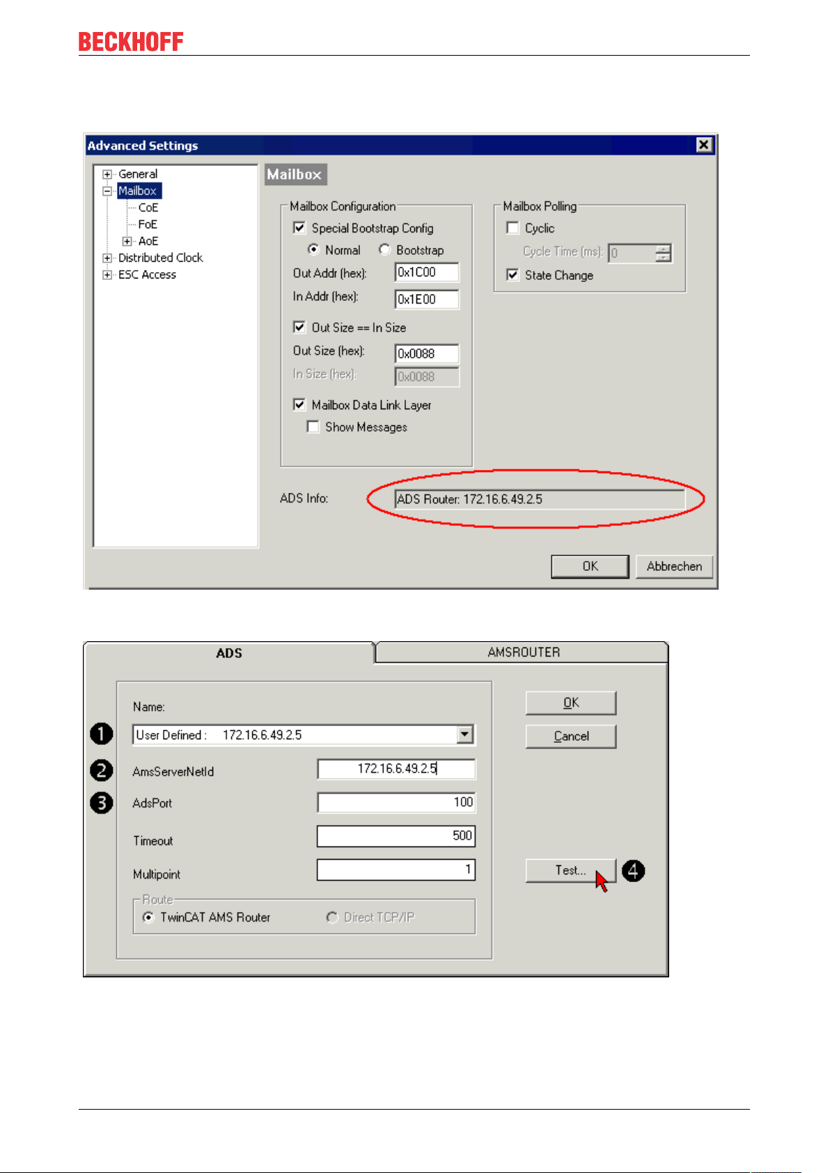
Configuration
• User Defined: For User Defined the AmsServerNetId has to be entered manually (2). Click on Test(4)
to check the connection settings.
Fig. 3: TwinCAT System Manager: "Mailbox" dialog, transfer of AmsServerNetID
Fig. 4: KS2000: "ADS" tab, enter the AmsServerNetID
Step 4
IL230x-B110 59Version: 1.0.3
Page 60

Configuration
The test was successful if the following dialog box appears (Fig. 5). Click OK to close the dialog box.
Fig. 5: KS2000: Confirmation of successful communication test
Step 5
Click OK to accept the set values (Fig.4).
Step 6
Log into the KS2000 system (see also KS2000 Documentation). Parameterization can now be carried out
according to the Bus Terminal configuration. Further information can be found in the associated terminal
documentation.
IL230x-B11060 Version: 1.0.3
Page 61

7 Error handling and diagnosis
7.1 Diagnostic LEDs - Overview
Error diagnosis
There are 2 sorts of errors:
• Fieldbus Errors [}62]
• Local Errors [}65] on Compact Box or Coupler Box
Error handling and diagnosis
Blink Codes
Blink sequence Meaning
Fast flashing Beginning of the Blink Code
first slow sequence Error code
second slow sequence Error argument
third slow sequence (optional) Error argument
Beginning Error code Error argument
IL230x-B110 61Version: 1.0.3
Page 62

Error handling and diagnosis
7.2 Diagnostic LEDs
After switching on, the module immediately checks the connected configuration. Error-free start-up is
indicated when the red I/O ERR LED goes out. If the I/O ERR LED blinks, an error in the area of the
terminals is indicated. The error code can be determined from the frequency and number of blinks. This
delivers a fast error elimination.
The module has two groups of LEDs for the display of status.
The upper group with four LEDs indicates the status of the respective fieldbus. The significance of the
fieldbus status LEDs is explained in the appropriate sections of this manual. It corresponds to the usual
fieldbus display.
At the lower end of the Module are two more green LEDs that indicate the supply voltage. The left hand LED
indicates the presence of the 24VDC supply for the Fieldbus Box. The right hand LED indicates the supply
voltage of the outputs.
The LEDs ACT and ERR are reserved and have no meaning at this time.
Fig.2: B110_ECAT_LED
IL230x-B11062 Version: 1.0.3
Page 63

Error handling and diagnosis
LEDs for fieldbus diagnosis
LED Display Status Meaning
LINK IN off - no connection with the
previous EtherCAT client
on linked previous EtherCAT-client
connected
blinking active communication with the
previous EtherCAT client
LINK OUT off - no connection with the
next EtherCAT client
on linked next EtherCAT client
connected
blinking active communication with the
next EtherCAT client
ACT - - reserved
ERR - - reserved
LEDs for EtherCAT State Machine/ PLC diagnosis
LED Display Status Meaning
RUN green off Init State of the
EtherCAT Fieldbus
Box: INIT =
Initialization
blinking Pre-Operational State of the
EtherCAT Fieldbus
Box: PREOP =
Pre-Operational
single flash Safe-Operational State of the
EtherCAT Fieldbus
Box: SAFEOP =
Safe-Operational
on Operational State of the
EtherCAT Fieldbus
Box: OP =
Operational
flickers Bootstrap State of the
EtherCAT Fieldbus
Box: BOOT =
Bootstrap (Update
of the coupler
firmware)
ERROR red off - no error
blinking Err-Operational
No Communication
PLC error / Lost
Frames
IL230x-B110 63Version: 1.0.3
Page 64
Error handling and diagnosis
Fig.3: FBB_power_LED
LEDs for power supply diagnosis
LED Meaning
left LED off Module has no operating voltage
left LED red Short circuit detection for sensor supply has released
(> 500mA). Sensors / inputs are not supplied.
right LED off No power supply 24VDC for outputs connected
IL230x-B11064 Version: 1.0.3
Page 65

Error handling and diagnosis
7.3 Diagnostic LEDs for local errors
Local error in a Coupler Box (IL230x-Bxxx/Cxxx)
The term local error means that an error has occurred in the Fieldbus Box or the IP-Link. IP-Link errors most
often turn out to be a result of inappropriate use of the optical fiber.
LED green LED red Description Remedy
off off No data
exchange
off 1 0 EEPROM
checksum error
off 2 Reserved off 3 Break location
has been
recognized
3 n Break location
has been
recognized
3 n m Break location
has been
recognized
off 4 n Too many faulty
telegrams have
been detected
(more than
25%)
off 5 n Register access
to complex
modules has
failed
off 11 n Complex
module working
incorrectly
off 12 n More than 120
modules in the
ring
off 13 n nth module
unknown
on off Module is
exchanging
data
Module in
synchronous
mode or activate
PROFIBUS
cyclic data
Set
manufacturer’s
setting with the
KS2000
software
interruption
before the
master's
receiver
n-th module
before the
master's
receiver
(n*10)+m-th
module before
the master's
receiver
The optical fiber
wiring in front of
the nth
extension
module should
be checked
Check the nth
module
Exchange the
nth module
Connect fewer
modules
Firmware
update required
no error
IL230x-B110 65Version: 1.0.3
Page 66

Error handling and diagnosis
Local errors in an Extension Box
LED green LED red Description
off on No data is being received over the
IP-Link
off blinks, flickers Faulty IP-Link protocols are being
received (very poor data
connection)
blinks, flickers blinks, flickers Faulty IP-Link protocols are being
received (poor data connection),
does not necessarily lead to an
error
on off IP-Link protocols are being
received, no error
Faulty protocols can occur, because of:
• bad configured IP-Link connectors
• IP-Link cable with higher dampening, e.g. because of a sharp curve
• contaminated sender LED (module before the faulty one)
• contaminated receiver
The internal IP-Link error counter of the Coupler Box can be read with the KS2000 software.
IL230x-B11066 Version: 1.0.3
Page 67
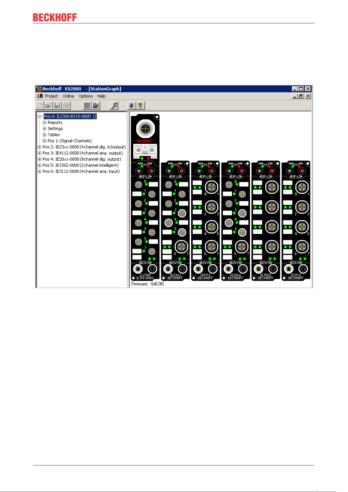
Error handling and diagnosis
7.4 Check of the IP-Link connection
A correct assembled IP-Link cable will assure an error free transmission.
An additional testing of the transmission quality and error diagnostics is possible with the KS2000
configuration software.
For this test, the fieldbus master (e.g. a PROFIBUS PC Card) should be on the bus and it should transmit
data cyclical. Another way to generate cyclic data is, to switch the coupler to free running via the KS2000
software.
The result should be, that the I/O RUN LED flashes in a bright green. This shows, that a data exchange with
the connected extension boxes takes place. A red blinking I/O ERR LED shows faulty IP-Link telegrams.
These faulty telegrams will be repeated automatically like in any other fieldbus system. This way a
transmission of the data is guaranteed.
Error counter
Table 90, offset 005 shows possible IP-Link errors. Sporadic appearing errors do not mean any problem for
the communication, as long as they do not reach a critical limit.
This error counter is only reset by the Power ON/OFF.
IL230x-B110 67Version: 1.0.3
Page 68
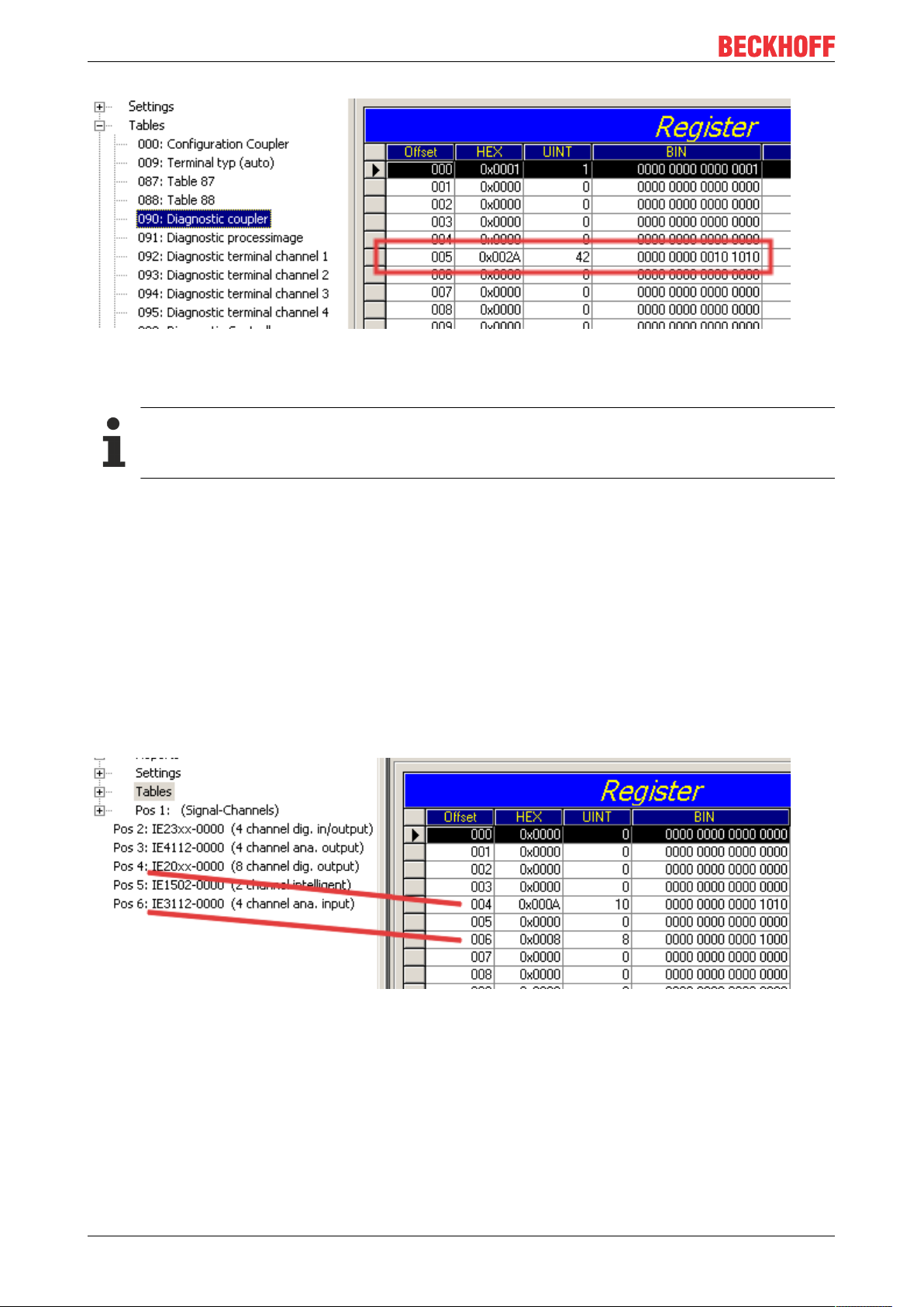
Error handling and diagnosis
If lots of errors occur in a very short time, this will be interpreted as a heavy disturbance of the
communication and the coupler box will report this error. This can be seen at offset 006 and 007. Both
values will show a value > 200 and the I/O ERR LEDs of the coupler box will blink the according error code.
Manual refresh needed
The KS2000 Configuration Software communicates with the Coupler Box via the serial channel.
The content of the registers will not be refreshed automatically and has to be refreshed manually.
Position of the error
In case of an IP-Link error, the Coupler Box tries to read the error location from the register of the Extension
Box. If the fiber optic ring is interrupted or the communication is heavily disturbed, this is not possible. Only
the position of the last functioning Extension Box before the receiver of the Coupler Box can be recognized.
The box will then flash this error code via the I/O ERR LED.
If the communication via IP-Link is still running, table 87 shows the error counter of each Extension Box.
The offset register corresponds to the position of the Extension Box in the KS2000 tree (left side of graphic).
This example shows errors at offset 004 and 006.
In the "real" world the faulty IP-Link telegram was reported from the IE20xx and the IE3112, that means the
problem has to looked for before these modules.
The error can be up to:
• the sending module
• the receiving module
• the IP-Link cable
• the connectors
If there is an error in table 90 and none in table 87, the faulty transmission is between the last Extension Box
and the Coupler Box.
IL230x-B11068 Version: 1.0.3
Page 69

Error handling and diagnosis
In most cases the transmission errors can be traced back to bad configured IP-Link connectors or a too high
attenuation of the cable due to sharp bending.
The values of table 87 directly come from the extension boxes. In case of an IP-Link interruption these
values will be set to zero and only table 90 can be used.
Operateon of a Coupler Box without Extension Modules
If you want to operate a Coupler Box (e.g. IL2300-Bxxx, IL2301-Bxxx or IL2302-Bxxx ) totally without Extension Modules (IExxxx), you have to connect the send and receive socket of this Coupler
Box directly by using an IP Link Cable! For this the IP Link Jumper ZK1020-0101-1000 fits perfect.
IL230x-B110 69Version: 1.0.3
Page 70

Accessories
8 Accessories
8.1 Fieldbus Box accessories
The necessary accessories for the Fieldbus Box Modules are also available from Beckhoff in protection class
IP67. You may get an overview from the Beckhoff catalog or from our internet pages (http://
www.beckhoff.com).
Fieldbus Accessories
• Pre-assembled cable
• Plug
• Distributor
Power supply
• Pre-assembled cable
• Plug
• Distributor
Sensor power supply
• Pre-assembled cable
• Plug
• Distributor
IP-Link
• Pre-assembled cable
• Plug
IL230x-B11070 Version: 1.0.3
Page 71

8.2 Power cables
Ordering data
Accessories
Order designation
ZK2020-3200-0
020
ZK2020-3200-0
050
ZK2020-3200-0
100
ZK2020-3400-0
020
ZK2020-3400-0
050
ZK2020-3400-0
100
ZK2020-3132-0
001
ZK2020-3132-0
005
ZK2020-3132-0
010
ZK2020-3132-0
020
ZK2020-3132-0
050
ZK2020-3334-0
001
ZK2020-3334-0
005
ZK2020-3334-0
010
ZK2020-3334-0
020
ZK2020-3334-0
050
Power lead Screw-in
connector
Straight socket,
M8 4-pin 0.34mm
open end
Angled socket,
open end
Straight socket,
straight socket
Angled socket,
angled socket
Contacts Cross-
section
Length
2
2.00m
5.00m
10.00m
2.00m
5.00m
10.00m
0.15m
0.50m
1.00m
2.00m
5.00m
0.15m
0.50m
1.00m
2.00m
5.00m
Further available power cables may be found in the Beckhoff catalog or on our internet pages (http://
www.beckhoff.com).
Technical data
Technical data
Rated voltage according to IEC60 664-1 60 VAC / 75 V
DC
Contamination level according to IEC 60 664-1 3/2
Insulation resistance IEC 60 512-2 >109W
Current carrying capacity according to IEC 60512-3 4 A
Volume resistance according to IEC 60512-2 < 5 mW
Protection class according to IEC 60529 IP65/66/67, when screwed together
Ambient temperature -30°C to +80°C
IL230x-B110 71Version: 1.0.3
Page 72

Appendix
9 Appendix
9.1 General operating conditions
Protection degrees (IP-Code)
The standard IEC 60529 (DIN EN 60529) defines the degrees of protection in different classes.
1. Number: dust protection
and touch guard
0 Non-protected
1 Protected against access to hazardous parts with the
2 Protected against access to hazardous parts with a
3 Protected against access to hazardous parts with a
4 Protected against access to hazardous parts with a
5 Protected against access to hazardous parts with a
6 Protected against access to hazardous parts with a
2. Number: water* protection Definition
0 Non-protected
1 Protected against water drops
2 Protected against water drops when enclosure tilted
3 Protected against spraying water. Water sprayed at
4 Protected against splashing water. Water splashed
5 Protected against water jets
6 Protected against powerful water jets
7 Protected against the effects of temporary immersion
Definition
back of a hand. Protected against solid foreign
objects of Ø50mm
finger. Protected against solid foreign objects of
Ø12,5mm.
tool. Protected against solid foreign objects Ø2,5mm.
wire. Protected against solid foreign objects Ø1mm.
wire. Dust-protected. Intrusion of dust is not totally
prevented, but dust shall not penetrate in a quantity
to interfere with satisfactory operation of the device or
to impair safety.
wire. Dust-tight. No intrusion of dust.
up to 15°.
an angle up to 60° on either side of the vertical shall
have no harmful effects.
against the disclosure from any direction shall have
no harmful effects
in water. Intrusion of water in quantities causing
harmful effects shall not be possible when the
enclosure is temporarily immersed in water for 30
min. in 1 m depth.
*) These protection classes define only protection against water!
Chemical Resistance
The Resistance relates to the Housing of the FieldbusBox and the used metal parts.
IL230x-B11072 Version: 1.0.3
Page 73

Character Resistance
Steam at temperatures >100°C: not resistant
Sodium base liquor
(ph-Value>12)
Acetic acid not resistant
Argon (technical clean) resistant
Key
resistant: Lifetime several months
non inherently resistant: Lifetime several weeks
not resistant: Lifetime several hours resp. early decomposition
at room temperature: resistant
> 40°C: not resistant
9.2 Approvals
Approvals
UL E172151
Appendix
Conformity mark
CE
Type of protection
IP65/66/67 in accordance with EN60529
9.3 Test standards for device testing
EMC
Resistance: EN 61000-6-2
Emission: EN 61000-6-4
Resistance to Vibration
EN 60068-2-2 Vibration test, Amplitude 2 g (Standard 1g)
EN 60068-2-27 Shock Test, Shock count 1000 (Standard 2)
IL230x-B110 73Version: 1.0.3
Page 74

Appendix
9.4 Support and Service
Beckhoff and their partners around the world offer comprehensive support and service, making available fast
and competent assistance with all questions related to Beckhoff products and system solutions.
Beckhoff's branch offices and representatives
Please contact your Beckhoff branch office or representative for local support and service on Beckhoff
products!
The addresses of Beckhoff's branch offices and representatives round the world can be found on her internet
pages: https://www.beckhoff.com
You will also find further documentation for Beckhoff components there.
Beckhoff Support
Support offers you comprehensive technical assistance, helping you not only with the application of
individual Beckhoff products, but also with other, wide-ranging services:
• support
• design, programming and commissioning of complex automation systems
• and extensive training program for Beckhoff system components
Hotline: +49 5246 963 157
Fax: +49 5246 963 9157
e-mail: support@beckhoff.com
Beckhoff Service
The Beckhoff Service Center supports you in all matters of after-sales service:
• on-site service
• repair service
• spare parts service
• hotline service
Hotline: +49 5246 963 460
Fax: +49 5246 963 479
e-mail: service@beckhoff.com
Beckhoff Headquarters
Beckhoff Automation GmbH & Co. KG
Huelshorstweg 20
33415 Verl
Germany
Phone: +49 5246 963 0
Fax: +49 5246 963 198
e-mail: info@beckhoff.com
web:
https://www.beckhoff.com
IL230x-B11074 Version: 1.0.3
Page 75

Page 76

Beckhoff Automation GmbH & Co. KG
Hülshorstweg 20
33415 Verl
Germany
Phone: +49 5246 9630
info@beckhoff.com
www.beckhoff.com
 Loading...