

Page 1
Technical Documentation for
FM33xx - TC-Plug
Applies to all FM33xx types
SW_VERSION 0xB0FA, 2000-25-05
Version: 1.6
Date: 2007-12-21
Page 2

Page 3

Table of contents
Table of contents
1. Foreword 1
Notes on the Documentation 1
Liability Conditions 1
Safety Instructions 2
Safety Rules 2
State at Delivery 2
Personnel Qualification 2
Description of safety symbols 2
2. Introduction 3
Overview 3
3. Technical data 3
Mechanical structure 3
Electrical data 4
Fieldbus-specific data 5
Pin assignment for the round connector 6
Pin assignment for the 24-pin connection strip 7
Pin assignment for the 64-pin connection strip 8
4. Functional description 9
The interfaces 9
Round connector 9
PE connection 10
Connecting strip for thermocouples 10
Configuration interface 10
Switches for the station address 10
Thermocouple measurement 11
Input circuits 11
Broken lead detection 11
Cold junction compensation 11
Back voltage protection 12
How the back voltage protection operates 12
Start-up procedure and diagnostics 13
Operating modes 13
Status display LEDs 13
Error codes for the thermocouple inputs 14
PROFIBUS error codes 14
Peripheral data in the process image 15
5. I/O configuration 16
Configuration in the TwinCAT System Manager 16
Configuring the PROFIBUS master 16
Linking of the TC-Plug 18
Linking the TC-Plug modules using the GSD file 20
Linking into the Simatic Manager 21
Configuration of the TC-Plug modules 22
Channel settings for the TC-Plug modules 23
Channel configuration by means of DPV1 services 24
Multiplex mode channel data in the TwinCAT System Manager 25
Protocol for the cyclical data transfer in multiplex mode 26
FM33xx
Page 4

Table of contents
6. Register description 27
General description of registers 27
TC-Plug - channel-specific register description 30
Register table 33
7. Appendix 34
Support and Service 34
Beckhoff's branch offices and representatives 34
Beckhoff headquaters 34
FM33xx
Page 5

Page 6

Foreword
Foreword
This description is only intended for the use of trained specialists in control
The responsible staff must ensure that the application or use of the
Notes on the Documentation
and automation engineering who are familiar with the applicable national
standards. It is essential that the following notes and explanations are
followed when installing and commissioning these components.
Liability Conditions
products described satisfy all the requirements for safety, including all the
relevant laws, regulations, guidelines and standards.
The documentation has been prepared with care. The products described
are, however, constantly under development. For that reason the
documentation is not in every case checked for consistency with
performance data, standards or other characteristics. None of the
statements of this manual represents a guarantee (Garantie) in the
meaning of § 443 BGB of the German Civil Code or a statement about the
contractually expected fitness for a particular purpose in the meaning of
§ 434 par. 1 sentence 1 BGB. In the event that it contains technical or
editorial errors, we retain the right to make alterations at any time and
without warning. No claims for the modification of products that have
already been supplied may be made on the basis of the data, diagrams
and descriptions in this documentation.
© This documentation is copyrighted. Any reproduction or third party use of
this publication, whether in whole or in part, without the written permission
of Beckhoff Automation GmbH, is forbidden.
FM33xx 1
Page 7
Foreword
The responsible staff must ensure that the application or use of the
All the components are supplied in particular hardware and software
This description is only intended for the use of trained specialists in control
The following safety symbols are used in this operating manual. They are
Safety Instructions
Safety Rules
products described satisfy all the requirements for safety, including all the
relevant laws, regulations, guidelines and standards.
State at Delivery
configurations appropriate for the application. Modifications to hardware or
software configurations other than those described in the documentation
are not permitted, and nullify the liability of Beckhoff Automation GmbH.
Personnel Qualification
and automation engineering who are familiar with the applicable national
standards.
Description of safety symbols
intended to alert the reader to the associated safety instructions.
This symbol is intended to highlight risks for the life or health of personnel.
Danger
This symbol is intended to highlight risks for equipment, materials or the
Warning
Note
environment.
This symbol indicates information that contributes to better understanding.
2 FM33xx
Page 8
Introduction
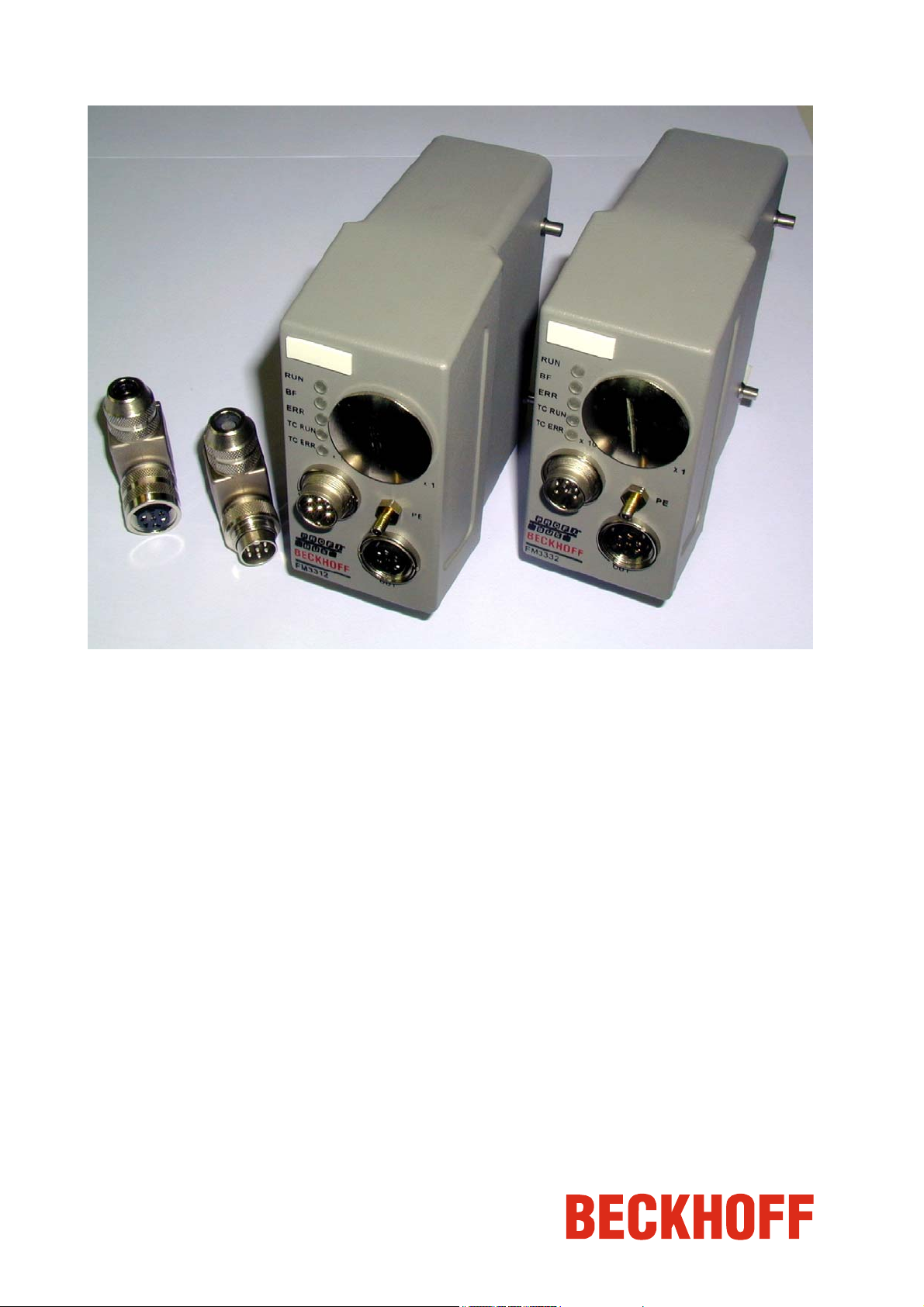
Introduction
The various implementation levels of the TC-Plug differ in the number of
Overview
thermocouple input channels (12 channels or 32) and in the type of
thermocouple implemented (J or K type).
Technical data
Side view of the TC-Plug
Mechanical structure
Technical data
(Version 1F.1 26.05.2000)
Dimensions
Connector Hood
Connector to Thermocouples
Contacts
Coding system
Power supply and PROFIBUS
connection
FM3312 FM3332
120mm x 52mm x 129mm, ,length x wide x height
Han24B (Harting)
Han24E Han64D
Hard gold plated
With coding pins in the connector
Round-Connector, DIN 45322 (series 423, 723 Binder)
Shield of the Round-Connector is connected to the plug
FM33xx 3
Page 9

Technical data
Electrical data
The following tables provide a summary of the electrical and fieldbus-
specific data related to the TC-Plug.
Technical data
(Version 1F.1 26.05.2000)
General technical data
Power supply
typical operating current
max. operating current
Power supply input protection
Reverse voltage
Over voltage
Potential separation
Thermocouples / PROFIBUS
Thermocouples / Supply Voltage
Supply Voltage / PROFIBUS
Ambient temperature
Operating temperature
Storage temperature
Type of protection
Vibration
Shock
Vibration
EMC immunity / EMC emission
Approvals
Thermocouple technical data
Number of Inputs
Type of Input
Connection
Wiring length
Thermocouple sensor type
Common mode input voltage range
Common mode rejection
Common mode rejection
Normal mode rejection
Resolution
Linearization Error
FM3312 FM3332
24 VDC, +- 20% (19,2...28,8 V)
90 mA (24 V) 100 mA (24 V)
120 mA (24 V) 130 mA (24 V)
min. -35V
max. 35V
500 V
500 V
100 V
0...+55°C
-25...+85°C
plug: IP65 (PROFIBUS-Connector: IP67)
EN 60068-2-6
10 Hz <= f <= 57 Hz: 0,075mm Amplitude
57 Hz <= f <= 150 Hz: 1,0 g
EN 60068-2-27/29
15 g, 11 ms
conforms to EN 60068-2-6 / EN 60068-2-27, EN 60068-2-29
conforms to EN 61000-6-2 / EN 61000-6-4
CE, cULus*
For the compliance of the cULus requirements use 4 Amp. fuse or
*)
class 2 power supply!
12 32
Differential Input,
mV measurement,
high impedance grounded
no electrical separation
two wire, direct connection
max. 10 meter
type K:-100...1370°C
type J:-100...900°C
-8 V...+8 V
typical 90 dB (independent from conversion time)
typical 150 dB (at 50 Hz or 60 Hz Rejection)
typical 98 dB (at 50 Hz or 60 Hz Rejection)
0.1°C per digit
+-0,1°C (voltage to temperature)
rms
rms
rms
4 FM33xx
Page 10

Technical data
Technical data
(Version 1F.1 26.05.2000)
Cold junction compensation Error
Calibration Error
Nonlinearity Error
Temperature Drift
Temperature nonlinearity
Cold junction compensation
Conversation time (per channel)
Data update time
Wiring fail indication
Back voltage indication
Back Voltage Range
Switch off time
Input resistance for current limitation
Input voltage
Input protection mechanism
Range of Input protection
Earth connection The plug must be connected to protective earth with the earth-
FM3312 FM3332
+- 0,1 C (voltage to temperature)
+- 0,3°C (Offset and linearization)
+- 0,1°C
+- 0,1°C
+- 0,2°C
+- 0,1°C
Internal (temperature measurement in the plug)
Adjustable
50 ms (60 Hz Common Mode Rejection)
60 ms (50 Hz Common Mode Rejection)
200 ms (60 Hz)
230 ms (50 Hz)
Yes (Open Thermocouple)
>10 V, < -10 V
3 ms, max.
2400 R, typical
100 Vac between TC+ and TC- of each channel
240 Vac above Protective Earth
415 Vac to other TC
Current limitation
Channel disconnect
240 Vac,dc
connector in the plug!
Fieldbus-specific data
Technical data
(Version 1F.1 26.05.2000)
Field bus protocol
Transmission rate
Address configuration
Status LED
FM3312 FM3332
PROFIBUS DP, EN50170
Max. 12Mbaud
Setting via two rotary switches
RUN, BF (Bus Failed), ERR (Error)
TC Run, TC Err
FM33xx 5
Page 11
Technical data
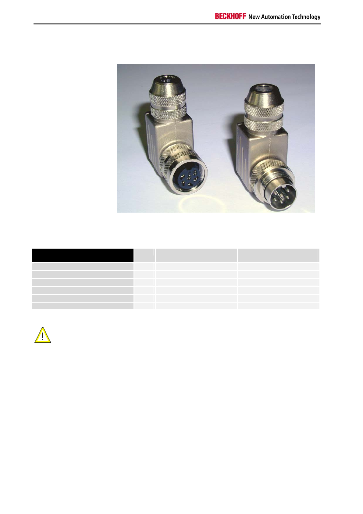
Pin assignment for the round connector
Round connectors
round connector
for input
round connector
for output
Pin assignment (Module) Male Connector
(Input)
PROFIBUS
PROFIBUS
PROFIBUS Termination
PROFIBUS Termination
Power supply
Power supply
pin 1 A = RxD / TxD-N A = RxD / TxD-N
pin 2 B = RxD / TxD-P B = RxD / TxD-P
pin 3 GND
pin 4 +5V
pin 5 +24V +24V
pin 6 0V 0V
Female Connector
(Output)
Protect the power supply (24 V) by using a fuse (max. 4 A, medium timelag), to protect the modules in case of short circuit at the hybrid cable
Attention
(PROFIBUS / Power Supply).
6 FM33xx
Page 12
Technical data
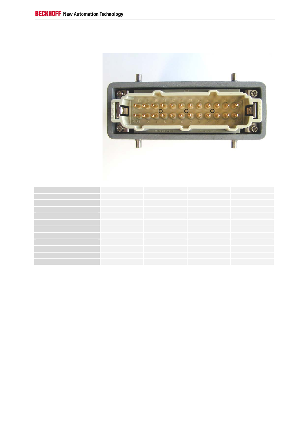
Pin assignment for the 24-pin connection strip
Pin assignment FM3312
pin 1 TC1+ pin 13 TC1pin 2 TC2+ pin 14 TC2pin 3 TC3+ pin 15 TC3pin 4 TC4+ pin 16 TC4pin 5 TC5+ pin 17 TC5pin 6 TC6+ pin 18 TC6pin 7 TC7+ pin 19 TC7pin 8 TC8+ pin 20 TC8pin 9 TC9+ pin 21 TC9pin 10 TC10+ pin 22 TC10pin 11 TC11+ pin 23 TC11pin 12 TC12+ pin 24 TC12-
FM33xx 7
Page 13

Technical data
Pin assignment for the 64-pin connection strip
Pin assignment FM3332
A.. B.. C.. D..
pin 1 TC1+ TC1- TC17+ TC17pin 2 TC2+ TC2- TC18+ TC18pin 3 TC3+ TC3- TC19+ TC19pin 4 TC4+ TC4- TC20+ TC20pin 5 TC5+ TC5- TC21+ TC21pin 6 TC6+ TC6- TC22+ TC22pin 7 TC7+ TC7- TC23+ TC23pin 8 TC8+ TC8- TC24+ TC24pin 9 TC9+ TC9- TC25+ TC25pin 10 TC10+ TC10- TC26+ TC26pin 11 TC11+ TC11- TC27+ TC27pin 12 TC12+ TC12- TC28+ TC28pin 13 TC13+ TC13- TC29+ TC29pin 14 TC14+ TC14- TC30+ TC30pin 15 TC15+ TC15- TC31+ TC31Pin 16 TC16+ TC16- TC32+ TC32-
8 FM33xx
Page 14

Functional description
Functional description
Status LEDs for the
PROFIBUScommunication
Status LEDs for the
thermocouple input
channels
Serial configuration
interface and switches
for station addresses
6-pin plug and socket
for fieldbus connection
The interfaces
The module has manual and electrical interfaces. The electrical interfaces
connect the PROFIBUS cable to the termination resistor and the power
supply for the fieldbus connection. For the temperature measurement, the
thermocouples are wired via the 24 or 64 pin connection strips and the PE
connection. The module also has a serial interface for configuration. The
module's station address can be set via the manual interface. The LEDs of
the visual display supply information about the current status of the TCPlug module.
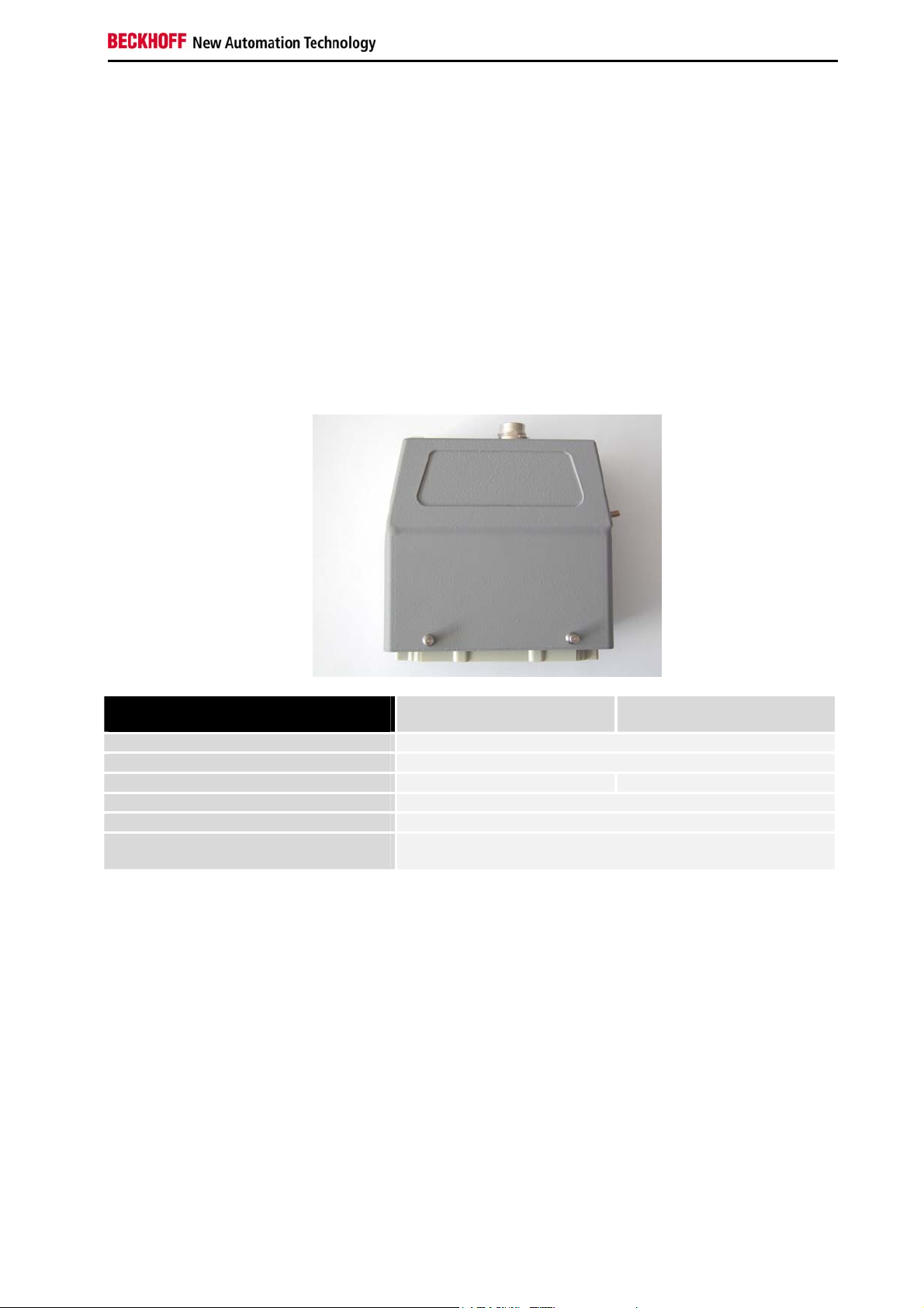
PE connection
Round connector
The round 6-pin connectors are used to connect the PROFIBUS cables
and the module's operating voltage. The operating voltage is fed via the
module's 6-pin male connector. The operating voltage is brought out on the
6-pin female connector side to supply the next module. The supply voltage
for the PROFIBUS cables is also fed in at the plug side and brought out
again on the socket side. The internal 5V bus voltage is brought out on the
socket side in order to supply the termination resistor. This voltage must
not be used for other purposes, and must not be connected elsewhere
through the cables. The screw threads on the round connector are in
metallic contact with the module housing, and provide a low-resistance
connection for the PE line. Grounding the screening braid on the
PROFIBUS cable is therefore effective.
FM33xx 9
Page 15

Functional description
Serial interface under the
screwed cover
PE connection
The screening braids on the PROFIBUS cables are to be earthed at the
modules, in accordance with the PROFIBUS specification. This
requirement is satisfied by a low-resistance connection between the PE
connection to the ground of the local environment (the machine). The PE
connection is also responsible for the potential equalization of grounded
and non-grounded thermocouples, and for thermocouples grounded at
different potentials (see thermocouple measurement). The back voltage
protection diverts mains voltages via the PE connection. This means that it
is essential for proper earthing of the module to be guaranteed. When the
module is being fitted, the PE connection should be established first.
Connection of the module to the thermocouples via the connecting strip
should be performed subsequently. In this way the risk of back voltage
being present at the thermocouple inputs during assembly is avoided. If the
earthing is inadequate the user is exposed to hazardous voltages on the
housing. When the module is being dismantled, the module should, for this
reason, first be disconnected from the thermocouples before the PE
connection is removed.
Connecting strip for thermocouples
The thermocouples are connected to the 24-pin or 64-pin connection strips.
The signal assignment and polarity must be correctly observed. Cold
junction compensation is implemented on the circuit board within the
module. The connection between the module electronics and the connector
pins is made with the corresponding thermal material. The use of
thermocouples other than those listed in the documentation is not
permitted. Good thermal conduction between the module's plug and socket
means that no significant thermal voltage is created by the plugged
connections. Thermal insulation on the socket side of the connection
should be ensured in order to avoid a large temperature error. Draughts
and unevenly heated areas in particular are to be avoided.
Configuration interface
The module has an RS232 interface at the top of the front panel under the
PG threaded fitting. The miniature connector can be linked through a
special cable to the serial interface of a PC. The module can be configured
with the KS2000 configuration software. The interface allows the analog
channels to be configured.
Switches for the station address
Two rotary switches are used to set the station address. The rotary
switches are located under the screwed cover next to the serial
configuration interface. The address is set as decimal number. The righthand rotary switch is for the units, and the left-hand switch sets the tens.
(Example: station address 18: left hand switch = 1, right hand switch = 8).
In order for a new station address that has been set to be permanently
stored in the module it must be reset (either by a brief interruption of the
power supply or by means of a software reset).
10 FM33xx
Page 16

Functional description
The thermocouples consist of two different metal alloys. Voltages
The module can contain up to 32 thermocouple inputs. Electrical isolation
Broken leads are detected as a diagnosis of the state of the thermocouple.
When a thermocouple is used for temperature measurement, a voltage is
Thermocouple measurement
proportional to the temperature arise where the alloys are in contact. In the
case of a type K thermocouple these voltages are typically in the range of
50 µV/°C. This means that the inputs for the thermocouples must be
capable of measuring voltages in the µV and mV range. In addition to the
signal measurement itself, the module performs functions related to error
detection, interference suppression and protection from external voltages.
Input circuits
between the channels could not be implemented, for reasons of both cost
and space. In order to exclude the possibility of mutual interference, every
input has a high-impedance differential amplifier. This rejects interfering
voltages that can be coupled into the thermocouple circuit. Voltage
differences between individual thermocouples are also suppressed without
them having any effect on one another. The conditioned measurement
signals are digitized with a sigma-delta converter, and are then transmitted
over the PROFIBUS.
Broken lead detection
The break is recognized through the infinite resistance of the broken
thermocouple. Broken leads are detected in both grounded and
ungrounded thermocouples.
Cold junction compensation
thermally generated at the other end of the connection as well as at the
location of the measuring junction. On both the 12-pin and the 64-pin
contact strips the socket contact at the module is connected to the thermal
wire. Other requirements mean that it is not possible to measure directly at
the socket contacts (plugging in without contact losses, and ability to
withstand mains voltage). There is another cold junction on the plug side,
opposite the cold junction on the socket side. Good temperature
equalization between the socket and plug contacts, and thermal insulation
of the socket and plug contacts, ensure that the thermal voltages on the
two sides are equalized. The voltages thus cancel each other out. To
achieve this structure, the connection in the module between the plug
contact and the circuit board is made with the necessary thermal material
in each case (J or K type). The resulting cold junction is then on the circuit
board for the module electronics. At this point it is possible to perform a
simple yet effective measurement of temperature in order to implement the
cold junction compensation.
FM33xx 11
Page 17

Functional description
Back voltage protection
The back voltage protection guards against external voltages applied
through the thermocouple inputs. Voltages of up to 230 V
are tolerated,
AC
or are withstood without damage to the module. Those thermocouple
inputs that are not affected remain functionally operative, or are only
affected for a short time. The module switches measurements from the
affected channel off and disconnects the voltage, so that the unwanted
voltage can remain connected to the thermocouple input for a long period.
If it is possible to manage without that particular thermocouple channel, it is
not necessary to rectify the fault immediately.
How the back voltage protection operates
The thermocouple inputs are protected within the module against voltages
that are outside the permitted signal range. The permitted range is about
–10V...+10V. If voltages outside this range appear, the current is limited by
an internal resistance and is diverted to a protective circuit. The currentlimiting function of the input circuit protects the thermocouple wires from
excessive short-circuit currents, so that they are not destroyed. A
protective circuit is responsible for a group of at most eight thermocouple
inputs. The central protective circuit detects the excess voltage and
switches off all the thermocouple inputs in the group. This process affects
the current measurements being taken by the channels in this group, and
those measurements will have to be made again. Monitoring and switching
groups off means that the channel that is directly affected cannot be
identified. The faulty thermocouple input is identified by switching on the
channels that have been switched off again one by one. As soon as it is
seen that the protective circuit for these thermocouple inputs is triggered
again after a channel is switched on, this channel is recognized as faulty,
and remains switched off. When all the channels in the group have been
tested, and are either operating again or have been switched off because
they are faulty channels, it is possible to continue with the normal
measuring process. The fault in the channels that have been switched off
is checked by switching on again after a configurable time, so that the
faulty channels can be automatically brought back into operation.
12 FM33xx
Page 18

Functional description
Start-up procedure and diagnostics
Installation guidelines
The PROFIBUS Nutzerorganisation e.V. technical guidelines must be
followed when installing and laying the PROFIBUS lead.
PROFIBUS-DP/FMS assembly guidelines
www.profibus.com
Operating modes
After being switched on, the TC-Plug carries out a self-test, and checks all
the functions of its components. If there is a fault, the TC-Plug enters the
"STOP" mode, but otherwise goes into the "fieldbus start" state.
Status display LEDs
The module has two groups of LEDs for the display of status. The upper
group contains three LEDs and indicates the state of the PROFIBUS, while
the lower group indicates the states of the thermocouple inputs.
RUN LED The “RUN” LED is illuminated cyclically by process data exchange over the
fieldbus.
BF LED The “BF" LED indicates any fieldbus errors.
ERR LED The “ERR" LED indicates the error code of any fieldbus error.
TC RUN The “TC RUN” LED is illuminated cyclically by process data exchange.
TC ERR The “TC ERR” LED indicates the error code for the thermocouple inputs.
Local errors The bottom two LEDs are used to indicate the operating status of the
thermocouple inputs. The green LED lights up in order to indicate fault-free
operation. The red LED blinks with two different frequencies in order to
indicate an error. The error is encoded in the blinks as follows:
Blink code
Fast blinking
First slow sequence
Second slow sequence
Start of the error code
Error code
Error code argument
Start of the error code Error type Error location
FM33xx 13
Page 19

Functional description
Error codes for the thermocouple inputs
Error code Error code argument Description Remedy
1 pulse
1 pulse
1 pulse
2 pulses 3 pulses
4 pulses
0 EEPROM checksum error
1 Inline code buffer overflow
2 Unknown data type
Programmed configuration
Faulty channel number. The
first faulty channel is indicated.
Faulty channel number. The
first faulty channel is indicated.
Back voltage
Open circuit
Fieldbus error The upper three LEDs indicate the operating status of the PROFIBUS. The
red ERR LED flashes with two different frequencies in order to indicate an
error. The sequence of flashes has the same structure as that for the "TC
ERR" LED. The first slow sequence follows the fast flashing, and the
second slow sequence follows this. The error is encoded in the blinks as
follows:
PROFIBUS error codes
I/O-RUN BF DIA Meaning Remedy
on
on
off
off
off
off off Operating state: RUN
Inputs are read and outputs are set.
on off,
blinking
off off Terminal bus cycles synchronized
on on No bus activity
on off,
blinking
1. Bus activity, but slave is not yet
parameterized
2. Bus error in which the outputs
a.) become 0
b.) remain unchanged
DP-watchdog switched off, no exchange
of data
Bus error, reaction
Terminal bus cycles are stopped
Everything is operating correctly
- Start master
- Check parameters
(-> Diagnostics data, DIA-LED)
- Check configuration
(-> Diagnostics data, DIA-LED)
PLC is in STOP mode, start PLC
- Start master
- Check bus cable
- Start master
- Check parameters
(-> Diagnostics data, DIA-LED)
- Check configuration
(-> Diagnostics data, DIA-LED)
ERR
1 pulse
2 pulses
0
n (n>0)
0
n (n>0)
Meaning Remedy
Not enough DP-Cfg data received.
Faulty DP-Cfg data byte.
Not enough User-Prm data received.
Faulty User-Prm data byte.
Check DP configuration.
Check DP user parameters.
14 FM33xx
Page 20

Functional description
Peripheral data in the process image
One 16 bit value is supplied for each configured channel in the minimal
configuration. In addition to this value there is a 32 bit value for open
circuit, a 32 bit value for back voltage, and a 16 bit status word.
32 channels can be configured in the maximal configuration.
D0..D31 Temperature in 1/10 degree Celsius (16 bit signed integer per
channel)
Open circuit One bit is reserved for each channel. If the channel is deactivated this bit
will always have the value zero. If a channel is activated, this bit will be set
to 1 when an open circuit is detected, and this fact is indicated through the
channel data by the limit value of the implemented thermocouple:
Limit values of the
thermocouples for an open
Type J: 900°C
Type K: 1370°C
circuit channel
Back voltage One bit is reserved for each channel, in a procedure similar to that for open
circuit. If excess voltage is detected at a channel, the corresponding bit is
set and the limit value of the implemented thermocouple is displayed.
Status word Each channel has a status word. The error bits in the status word are set
when an error is detected, and have the following meaning:
Error message Bit
OVERRANGE 0
UNDERRANGE 1
CHERROR 6
Underrange, Overrange and Error are all set if there is an open circuit.
Depending on whether the thermocouple is grounded or not, the ADC
value will go to 0x8000 or 0xFFFF.
FM33xx 15
Page 21

I/O configuration
I/O configuration
The TC-Plug modules can be configured with a configuration software that
supports the integration of the modules via a GSD file. TC-Plug modules
are slave modules conforming to PROFIBUS.
Multiplex mode and simple
mode
The TC-Plug modules can be operated in two modes. Different GSD files
are required, depending on whether the TC-Plug is to be configured in
multiplex or simple mode. Multiplex mode enables the quantity of data
transferred via the fieldbus to be minimized. In this mode, communication
with the TC-Plug occurs via the status/control word, and at the same time
the channel data from a maximum of 4 channels are transferred via the
fieldbus (see chapter: Protocol for the cyclic transfer in multiplex mode).
For most applications, the TC-Plug can be operated in simple mode. In this
mode, the channel data from a maximum of 32 channels can be
transferred at the same time via the fieldbus. The simple mode is easier to
configure and is recommended for most applications.
Configuration in the TwinCAT System
Manager
This section describes the configuration of the TC-Plug modules with the
TwinCAT System Manager. A PROFIBUS master card such as the
CP5412A2 from Siemens can be used as the master. The configuration of
a TC-Plug module with the CP5412A2 is described below.
If the right mouse button is clicked on the I/O Devices branch in the
Add a PROFIBUS master
Configuring the PROFIBUS master
TwinCAT System Manager, the following context menu appears.
Using the menu command Append Device… a PROFIBUS master can be
inserted into the configuration. The PROFIBUS master card can be
selected in the dialog box which then opens.
16 FM33xx
Page 22

I/O configuration
Available PROFIBUS
master cards
After you have confirmed with OK the master card appears in the branch
that shows the configured I/O devices. A mouse click on the CP5412 will
open a dialog box on the right with the master's configuration settings
Configuring the master card
The port number, address range and baud rate must be set on the
CP 5412 tab. Baud rates up to 12 Mbaud are supported by the TC-Plug,
and the port number can be found automatically with the Search.. menu
command. The address range should be selected in such a way that no
conflict with other hardware is caused.
FM33xx 17
Page 23

I/O configuration
Linking of the TC-Plug
Clicking with the right mouse button on the CP5412A2 master card causes
the following context menu to appear in the TwinCAT System Manager:
Adding of the PROFIBUS
slaves
The menu command Append Box… opens a dialogue with all the available
PROFIBUS slaves.
FM33xx or FM33xx (multiplex mode) is selected from the list, depending on
whether the TC-Plug is to be operated in simple or multiplex mode. Select
FM33xx (simple mode) from the list and confirm with OK. A new box
(slave) will be added to the configuration tree.
In the next step, the individual modules are appended. Click with the right
mouse button on the FM3xx box and select Append module... from the
context menu.
add TC-Plug modules
18 FM33xx
Page 24

I/O configuration
A dialogue with the available modules will appear.
The modules are added in the following order:
• Add Channel compact. Repeat n times for n channels;
• Add Channel State Open Circuit;
• Add Channel State Back Voltage;
• Add Measure Control;
• Add Measure State;
TC-Plug example
configuration in simple
mode with 2 channels
TC-Plug example
configuration in multiplex
mode
FM33xx 19
Page 25

I/O configuration
Linking the TC-Plug modules using the GSD file
The TC-Plug modules can be linked into the TwinCAT System Manager
through a GSD file. A GSD file can configure any PROFIBUS slave in the
TwinCAT System Manager. Clicking with the right mouse button on the
CP5412A2 master card causes the following context menu to appear in the
TwinCAT System Manager:
Adding a TC-Plug module
to the I/O configuration
The menu command Append Box… opens a dialogue with all the available
PROFIBUS modules.
Linking a slave using the
GSD file
If the Generic Profibus Box is selected, a File Open dialog box appears.
The corresponding TC-Plug GSD file can be selected in this dialog window.
Once you have confirmed with OK, the TwinCAT System Manager reads
the device-specific parameters from the GSD file and inserts the TC-Plug
into the existing configuration.
20 FM33xx
Page 26

I/O configuration
Linking into the Simatic Manager
The following steps are required for linking the TC-Plug into the Simatic
Manager in simple mode and for configuring it.
• Install the GSD file in the Simatic Manager, add the module in the
hardware configuration and set the PROFIBUS address;
• Data format: MOTOROLA; Connection Channel 0: Channel
connected; set;
• n times for n channels: Add Channel compact, set the required I-
addresses for the data;
• Append Channel State Open Circuit;
• Append Channel State Back Voltage;
• Append Measure Control;
• Append Measure State;
• Download the configuration into the station;
• Start master;
• Reset TC-Plug by switching it on and off (power is removed);
FM33xx 21
Page 27

I/O configuration
Configuration of the TC-Plug modules
Clicking with the mouse on a TC-Plug module in the I/O configuration tree
permits the necessary configuration settings to be made on the tabs:
The station number of the TC-Plug module must correspond to the station
number physically set with the rotary switches.
The "User Parameter Data" can easily be configured in a dialog box on the
PrmData(Text) tab.
The dialog box displays the most important TC-Plug PROFIBUS parameter
data in textual form, and this can be configured by the user. A double
mouse-click on one of the parameters will open a selection menu showing
the available parameters.
Data format
The analog thermocouple inputs can be evaluated either in Intel or in
Motorola format.
s
The reaction to a fieldbus or I/O error can be configured through
associated parameters.
Reaction on PROFIBUSfault
22 FM33xx
Page 28

I/O configuration
Reaction on I/O-fault
Channel settings for the TC-Plug modules
The number of active analog channels can be configured by means of the
channel settings. Only the data of the channels that are associated are
transmitted over the fieldbus and can be evaluated. At least one channel
must be associated in the minimal configuration. A maximum of 32
channels can be associated through the configuration. If a channel is to be
associated, the user can choose between complex or compact mapping of
the channel data. Only compact mapping is presently supported. This
means that 16 data bits are transmitted over the fieldbus for each channel.
Configuring the channels
At least one channel must be configured in the minimal configuration. This
means that a compact association must be configured for at least one
channel.
FM33xx 23
Page 29

I/O configuration
Channel configuration by means of DPV1 services
Channel configuration over
the fieldbus
The channels of the TC-Plug module can be activated or deactivated over
the fieldbus by means of the DPV1 Services. Once the configuration was
changed, the vendor settings can only be set back with the configuration
software KS2000. The module holds the new configuration settings after
TwinCAT restart and after the Power-Off of the TC-Plug module. You can
call the DPV1-Services from the PLC by means of the ADSWRITE function
block. The ADSWRITE function block can be found in the PLC library
PlcSystem.Lib. The Ads parameters have following values:
If you use CP5412A2 as master:
NETID = NetId of the TwinCAT System;
PORT = Port number from the TC-Plug -> Ads tab in the TwinCAT System
Manager;
IDXGRP = 0x0;
IDXOFFS = 0x1;
LEN = 1 until max. 16 Byte configuration data;
SRCADDR =Pointer to the data buffer with the configuration data;
If you use FC310x as Master:
NETID = NetId of the FC310x card in the TwinCAT System Manager;
PORT = 0x1000 + Station number of the TC-Plug module;
IDXGRP = 0x0;
IDXOFFS = 0x1;
LEN = 1 until max. 16 Byte configuration data;
SRCADDR =Address of the data buffer with the configuration data;
Maximal 4 channels can be switched on or off by the means of one byte in
the configuration data. Every channel uses 2 bits of configuration data
which tells if its activated or not. The channel is deactivated if one of the
two bits is 1 and activated if both bits are zero. The thermo outputs are set
to zero during the change of the TC-Plug configuration.
Example:
We want to change the configuration for the first 4 channels of the TC-Plug
module. From the PLC we write one byte of configuration data ( 10000001
binary ) to the TC-Plug module. After that the channels 1 and 4 are
deactivated and channels 2 and 3 are activated. The configuration of all
other channels stays unchanged.
Remark: channel no. 1 is the very first TC channel connected to Pin 1 .
24 FM33xx
Page 30

I/O configuration
Multiplex mode channel data in the
TwinCAT System Manager
The channel data of a TC-Plug module is mapped and displayed as follows
in the TwinCAT System Manager, independently of the number of channels
that are configured (associated):
Process data for the TCPlug modules in the
TwinCAT System Manager
Control/status
byte
Channel
Control/status byte and
channel data for the 4
thermocouple inputs
In order to reduce the quantity of data that has to be transferred over the
fieldbus, the thermocouple input data for a maximum of 4 channels only
(e.g. for channels 0 to 3) is transferred over the fieldbus in any one fieldbus
cycle. The control/status byte can be used to request the analog values of
another 4 channels (e.g. for channels 4 to 7, 8 to 11 etc.).
FM33xx 25
Page 31

I/O configuration
Protocol for the cyclical data transfer in
multiplex mode
The following protocol has been specified for communication with the TC-
Plug module in order to reduce the quantity of data transferred over the
fieldbus.
Appropriate channel selection request bits are set by the PLC in the control
byte. The channel selection request bits select the 4 channels that are to
be transferred. The TC-Plug copies the corresponding data in the input
bytes [1-8] and confirms it in the channel confirmation bits of the status
byte. If the control byte == status byte, then the data is valid.
Control byte Value Description
Channel Selection Request
Bits 0-3
1
2
3
4
5
6
7
8
9
Bit 4-6 Bit 7 1/0
Status byte Value Description
Channel Selection
Confirmation Bits 0-3
1
2
3
4
5
6
7
8
9
Bit 4-6 Bit 7 1/0
The AD conversion of the thermocouple input data in the TC-Plug module
During a conversion procedure the TC-Plug converts all its active
0
0
no channel selected
Channel 0-3 in Input Data [1..8]
Channel 4-7 in Input Data [1..8]
Channel 8-11 in Input Data [1..8]
Channel 12-15 in Input Data [1..8]
Channel 16-19 in Input Data [1..8]
Channel 20-23 in Input Data [1..8]
Channel 24-27 in Input Data [1..8]
Channel 28-31 in Input Data [1..8]
Status (Open circuit Channel 0-31 in Input Data [1..4] and Back Voltage in
Input Data [5..8])
Reserved for future use
Toggle-Bit Measure Control
no channel selected
Channel 0-3 in Input Data [1..8]
Channel 4-7 in Input Data [1..8]
Channel 8-11 in Input Data [1..8]
Channel 12-15 in Input Data [1..8]
Channel 16-19 in Input Data [1..8]
Channel 20-23 in Input Data [1..8]
Channel 24-27 in Input Data [1..8]
Channel 28-31 in Input Data [1..8]
Status (Open circuit Channel 0-31 in Input Data [1..4] and Back Voltage in
Input Data [5..8])
Reserved for future use
Toggle-Bit Measure Status
can be initiated by the PLC by toggling bit 7 in the control byte. After the bit
has been toggled, the status and control bytes have different values in
bit 7. When the measuring cycle in the TC-Plug module has been
completed the TC-Plug will also toggle bit 7 in the status byte. The toggled
bits in the status and control bytes then have the same value.
By setting the appropriate channel selection request bits the PLC can then
request the current thermocouple input data. Every request in the control
byte is appropriately acknowledged in the status byte by the TC-Plug.
configured channels. Once completed, the PLC can request the channel
data over a number of cycles.
26 FM33xx
Page 32

Register description
The open circuit and back voltage status information is also requested in a
similar manner by means of the channel selection control bits. When these
have been confirmed in the status byte the status information can be read
from the data for the 4 channels. For each channel that is registering open
circuit, one bit is set in bytes 1 to 4, while bits are set in bytes 5 to 8 for
channels registering back voltage.
Register description
The registers for a channel can be written to if the code word 0x1235 is
The TC-Plug can be configured via the serial interface using the KS2000
configuration software. The individual thermocouple input channels are
represented in the configuration software as complex terminals.
Each logical thermocouple input channel has its own set of registers.
Various operating modes and functionalities can be set for each channel by
means of the registers.
The "General Description of Registers" explains those register contents
that are the same for all complex terminals.
The terminal-specific registers are explained in the following section.
entered in R31 (register 31). The data is only permanently stored when the
code word is cleared and the module is reset.
General description of registers
Complex terminals that possess a processor are able to exchange data bidirectionally with the higher-level controller. These terminals are referred to
below as intelligent Bus Terminals. These include the analog inputs (0-10
V, -10-10 V, 0-20 mA, 4-20 mA), the analog outputs (0-10 V, -10-10 V, 020 mA, 4-20 mA), the serial interface terminals (RS485, RS232, TTY, data
exchange terminals), counter terminals, encoder interface and SSI
interface terminals, PWM terminals and all the terminals that can be
parameterized.
The main features of the internal data structure are the same for all the
intelligent terminals. This data area is organized as words and includes 64
memory locations. The important data and parameters of the terminal can
be read and set through this structure. It is also possible for functions to be
called by means of corresponding parameters. Each logical channel in an
intelligent terminal has such a structure (so a 4-channel analog terminal
has 4 sets of registers).
FM33xx 27
Page 33

Register description
The structure of a register set is divided into the following areas:
Range Address
Process variables
Type register
Manufacturer parameters
User parameters
Extended user region
0-7
8-15
16-30
31-47
48-63
Process variables
R0-R7 Registers in the terminal's internal RAM:
The process variables can be used in addition to the actual process image.
Their function is specific to the terminal.
R0-R5:
The function of these registers depends on the type of terminal.
R6: Diagnostic register
The diagnostic register can contain additional diagnostic information. Parity
errors, for instance, that occur in a serial interface during data transmission
are indicated here.
R7: Command register
High-Byte_Write = function parameter
Low-Byte_Write = function number
High-Byte_Read = function result
Low-Byte_Read = function number
Type register
R8-R15 Registers in the terminal's internal ROM:
The type and system parameters are hard programmed by the
manufacturer, and the user can read them but cannot change them.
R8: Terminal type:
The terminal type in register R8 is needed to identify the terminal.
R9: Software version X.y
The software version can be read as a string of ASCII characters.
R10: Data length
R10 contains the number of multiplexed shift registers and their length in
bits.
The Bus Coupler sees this structure.
R11: Signal channels
Related to R10, this contains the number of channels that are logically
present. Thus for example a shift register that is physically present can
perfectly well consist of several signal channels.
R12: Minimum data length
The particular byte contains the minimum data length for a channel that is
to be transferred. If the MSB is set, the control/status byte is not absolutely
necessary for the terminal's function, and if the coupler is appropriately
configured it is not transferred to the controller.
28 FM33xx
Page 34

Register description
R13: Data type register
Data type register
0x00
0x01
0x02
0x03
0x04
0x05
0x06
0x07
0x08
0x11
0x12 Structure 1 byte n bytes with variable logical channel
0x13
0x14 Structure 1 byte n words with variable logical channel
0x15
0x16 Structure 1 byte n double words with variable logical
Terminal with no valid data type
Byte array
Structure 1 byte n bytes
Word array
Structure 1 byte n words
Double word array
Structure 1 byte n double words
Structure 1 byte 1 double word
Structure 1 byte 1 double word
Byte array with variable logical channel length
length (e.g. 60xx)
Word array with variable logical channel length
length
Double word array with variable logical channel length
channel length
R14: reserved
R15: Alignment bits (RAM)
The analog terminal is placed on a byte boundary in the terminal bus with
the alignment bits.
Manufacturer parameters
R16-R30 is the region for the "manufacturer parameters" (SEEROM)
The manufacturer parameters are specific for each type of terminal. They
are programmed by the manufacturer, but can also be modified by the
controller. The manufacturer parameters are stored in a serial EEPROM in
the terminal, and are retained in the event of voltage drop-out.
These registers can only be altered after the code word has been set in
R31.
User parameters
R31-R47 is the "application parameters" region (SEEROM)
The application parameters are specific for each type of terminal. They can
be modified by the programmer. The application parameters are stored in a
serial EEPROM in the terminal, and are retained in the event of voltage
drop-out. The application region is write-protected by a code word.
R31: Code word register in RAM
The code word 0x1235 must be entered here so that parameters in the
Note
user area can be modified. If any other value is entered into this register,
the write-protection is active. When write protection is not active, the code
word is returned when the register is read. If the write protection is active,
the register contains a zero value.
R32: Feature register
This register specifies the terminal's operating modes. Thus, for instance, a
user-specific scaling can be activated for the analog I/Os.
R33 - R47
Registers that depend on the terminal type
Extended application region
R47 - R63
Extended registers with additional functions.
FM33xx 29
Page 35

Register description
TC-Plug - channel-specific register
description
Process variables
R0: Unprocessed ADC value X_R
This register contains the unprocessed ADC value.
R1: Unprocessed ADC value for the cold junction compensation
R2: Temperature of the cold junction compensation
Unit: 1/10 degree Celsius, 16-bit signed int
R6: Diagnostic register
High byte: reserved
Low byte: status byte
R7: Command register
Commands:
0x0101
Offset adjustment with short-circuited input. An automatic offset
adjustment is carried out. At the same time the unprocessed ADC value
with which the cold junction compensation was carried out is kept in R23.
The corresponding inputs are to be short-circuited.
0x0102
Gain adjustment at 30 mV. An automatic gain adjustment is carried out on
the assumption that 30 mV is present at the corresponding input.
0x0103
Adjustment for temperature drift with short-circuited input. An offset
adjustment should be carried out at room temperature. This function is
called in order to take account of temperature drift. The comparison
temperature is entered into R24, and the corresponding coefficient into
R22.
R17: Calibration offset
In order to carry out a calibration, a zero is entered into R32 and R17, and
a comparison with 0 V is made. The process data value (in microvolts) is
multiplied by -1.9074, and entered into R17.
R18: Calibration gain
Value: [4096]
R19: Manufacturer scaling offset
Value: [0x0000]
R20: Manufacturer scaling gain
Fixed point number /256, so that 1 corresponds to a value of 256
30 FM33xx
Page 36

Register description
R21: Cold junction compensation adjustment
Unit: 1/10 degree Celsius, 16-bit signed int
There are 8 cold junction compensations, and these are distributed as
follows. The cold junction compensation is purely an offset adjustment.
Comp[0] Channel0 R21
Comp[1] Channel4 R21
Comp[2] Channel8 R21
Comp[3] Channel12 R21
Comp[4] Channel16 R21
Comp[5] Channel20 R21
Comp[6] Channel24 R21
Comp[7] Channel28 R21
The cold junction compensation for a channel is calculated as follows:
Cold junction compensation =
(((~channel) & 0x7) * U_compensation [(channel>>3)<<1]+(channel &
0x7) *U_compensation[((channel>>3)<<1)+1])/7;
e.g., for channel 20:
4/7*U_compensation[5]+3/7*U_compensation[4]
R26: Number of hardware channels valid
12 with the number of channels 0 - 12
the hardware is different => the two outer boards are inserted
all values != 12 result in a standard version
R32: Feature register
R32.0 1 User scaling active
0 User scaling inactive
R32.1 1 Manufacturer scaling active
0 Manufacturer scaling inactive
R32.2 1 Cold junction compensation is active
0 Cold junction compensation is inactive
R32.7...R32.4 0x0000 Output in 2 microvolts / digit
R32.7...R32.4 0x0001 Type K active
R32.7...R32.4 0x0010 Type J active
R32.7...R32.4 0x1110 Output the unprocessed ADC value in the process
data. Default output in 2 microvolts / digit.
R33: User scaling offset
R34: User scaling gain
Fixed point number /256,
so that 1 corresponds to a value of 256.
FM33xx 31
Page 37

Register description
R37: Filter register
with the following possible entries:
The changes can only be made by way of the first channel, and are
adopted after a reset.
Entry – Conversion time – Suppression
0x0C 191 ms with 4.9 MHz 50 Hz filter
0x0D 160 ms with 4.9 MHz 60 Hz filter
0x0E 46 ms with 4.9 MHz 250 Hz filter
0x0F 30 ms with 4.9 MHz 500 Hz filter
R38: Back voltage reset time
Unit is seconds. Minimum value is 10 seconds. If an error occurs, another
attempt is made to activate the channel after the specified interval.
Measurement is then not carried out for one cycle.
32 FM33xx
Page 38

Register description
Register table
Register set
Address Description
R0
Unprocessed ADC value Variable R RAM
R1 Unprocessed ADC value for the cold junction
compensation
R2
Temperature of the cold junction compensation
Unit: 1/10 degree Celsius, 16-bit signed int
R3
reserved 0x0000 R
R4
reserved 0x0000 R
R5
reserved 0x0000 R
R6
Diagnostic register Variable R RAM
R7
Command register Variable R
R8
reserved 0x0000 R ROM
R9
reserved 0x0000 R ROM
R10
R11
R12
R13
R14
R15
R16
R17
R18
R19
R20
R21
R22
R23
R24
R25
R26
R27
R28
R29
R30
R31
R32
R33
R34
R35
R36
R37
R38
reserved 0x0000 R ROM
reserved 0x0000 R ROM
reserved 0x0000 R ROM
reserved 0x0000 R ROM
reserved 0x0000 R
reserved 0x0000 R/W RAM
reserved 0x0000 R/W SEEROM
Calibration offset 0x0000 R/W SEEROM
Calibration gain app. 0x1ED8 R/W SEEROM
Manufacturer scaling offset [0x0000] R/W SEEROM
Manufacturer scaling gain [0x0100] R/W SEEROM
Cold junction compensation adjustment Specific R/W SEEROM
reserved 0x0000 R/W SEEROM
reserved 0x0000 R/W SEEROM
reserved 0x0000 R/W SEEROM
reserved 0x0000 R/W SEEROM
Number of hardware channels valid Specific R/W SEEROM
reserved 0x0000 R/W SEEROM
reserved 0x0000 R/W SEEROM
reserved 0x0000 R/W SEEROM
reserved 0x0000 R/W SEEROM
Code word Variable R/W RAM
Feature register Variable R/W SEEROM
User scaling offset [0x0000] R/W SEEROM
User scaling gain [0x0100] R/W SEEROM
reserved 0x0000 R/W SEEROM
reserved 0x0000 R/W SEEROM
Filter register 0x000D R/W SEEROM
Back voltage reset time 0x000A R/W SEEROM
Default
value
Variable R
0x0000 R
R/W Memory medium
FM33xx 33
Page 39

Appendix
Appendix
Support and Service
Beckhoff and their partners around the world offer comprehensive support and service, making available
fast and competent assistance with all questions related to Beckhoff products and system solutions.
Beckhoff's branch offices and representatives
Please contact your Beckhoff branch office or representative for local support and service on Beckhoff
products!
The addresses of Beckhoff's branch offices and representatives round the world can be found on her
internet pages: http://www.beckhoff.com
You will also find further documentation for Beckhoff components there.
Beckhoff headquaters
Beckhoff Automation GmbH
Eiserstr. 5
33415 Verl
Germany
Phone: +49(0)5246/963-0
Fax: +49(0)5246/963-198
e-mail: info@beckhoff.com
web: www.beckhoff.com
Beckhoff Support
Support offers you comprehensive technical assistance, helping you no only with the application of
individual Beckhoff products, but also with other, wide-ranging services:
• world-wide support
• design, programming and commissioning of complex automation systems
• and extensive training program for Beckhoff system components
Hotline: +49(0)5246/963-157
Fax: +49(0)5246/963-9157
e-mail: support@beckhoff.com
Beckhoff Service
The Beckhoff Service Center supports you in all matters of after-sales service:
• on-site service
• repair service
• spare parts service
• hotline service
Hotline: +49(0)5246/963-460
Fax: +49(0)5246/963-479
e-mail: service@beckhoff.com
34 FM33xx
 Loading...