

Page 1
Documentation | EN
Fieldbus Box for PROFIBUS
2009-10-29 | Version: 1.2.1
Page 2

Page 3

Table of contents
Table of contents
1 Foreword ....................................................................................................................................................5
1.1 Notes on the documentation..............................................................................................................5
1.2 Safety instructions .............................................................................................................................6
1.3 Documentation issue status ..............................................................................................................7
2 Product Overview ......................................................................................................................................8
2.1 The Fieldbus Box System..................................................................................................................8
2.2 Fieldbus Box - Naming conventions ................................................................................................10
2.3 Firmware and hardware issue status...............................................................................................12
2.4 Technical Data.................................................................................................................................13
2.4.1 Modules - Technical Data ................................................................................................ 13
2.4.2 Controller - Technical Data .............................................................................................. 13
2.4.3 Current Consumption....................................................................................................... 14
3 Profibus ....................................................................................................................................................18
3.1 Fieldbus Overview ...........................................................................................................................18
3.2 Topology..........................................................................................................................................22
3.3 Application .......................................................................................................................................23
3.4 PROFIBUS Cabling .........................................................................................................................24
3.4.1 PROFIBUS Cabling ......................................................................................................... 24
3.4.2 PROFIBUS Connection ................................................................................................... 27
3.5 Protocol Description ........................................................................................................................29
3.5.1 Process Data ................................................................................................................... 29
3.5.2 Configuration Data (Cfg Data) ......................................................................................... 30
3.5.3 Activating the DPV1 Functions ........................................................................................ 31
3.6 Description of the Parameter Data ..................................................................................................33
3.6.1 General ............................................................................................................................ 33
3.6.2 Parameter Data ............................................................................................................... 41
4 Parameterization and commissioning...................................................................................................44
4.1 Start-up behavior of the Fieldbus Box .............................................................................................44
4.2 Addressing.......................................................................................................................................45
4.3 Baud Rate........................................................................................................................................46
4.4 Configuration ...................................................................................................................................47
4.4.1 Configuration Data (Cfg Data) ......................................................................................... 47
4.4.2 Configuration of the complex Modules ............................................................................ 56
5 Diagnostic LEDs ......................................................................................................................................62
5.1 Diagnostic LEDs for PROFIBUS .....................................................................................................62
5.2 Diagnostic LEDs for local errors ......................................................................................................65
5.3 Check of the IP-Link connection......................................................................................................67
5.4 Trouble Shooting .............................................................................................................................70
5.5 Diagnostic Telegrams......................................................................................................................71
5.5.1 Diagnostic Telegrams Overview ...................................................................................... 71
5.5.2 Diagnostic Telegrams for the Compact Box (IPxxx-B3xx)............................................... 71
5.5.3 Diagnostic Telegrams for the Coupler Box (IL230x-B3xx)............................................... 73
5.5.4 TwinCAT - Example for Diagnostics with the FC310x Fieldbus Card.............................. 76
3Version: 1.2.1
Page 4

Table of contents
6 Accessories .............................................................................................................................................78
6.1 PROFIBUS Accessories..................................................................................................................78
6.2 Fieldbus Box accessories................................................................................................................83
7 Appendix ..................................................................................................................................................84
7.1 General operating conditions...........................................................................................................84
7.2 Approvals.........................................................................................................................................86
7.3 Test standards for device testing.....................................................................................................87
7.4 Support and Service ........................................................................................................................88
4 Version: 1.2.1
Page 5

Foreword
1 Foreword
1.1 Notes on the documentation
Intended audience
This description is only intended for the use of trained specialists in control and automation engineering who
are familiar with the applicable national standards.
It is essential that the documentation and the following notes and explanations are followed when installing
and commissioning these components.
It is the duty of the technical personnel to use the documentation published at the respective time of each
installation and commissioning.
The responsible staff must ensure that the application or use of the products described satisfy all the
requirements for safety, including all the relevant laws, regulations, guidelines and standards.
Disclaimer
The documentation has been prepared with care. The products described are, however, constantly under
development.
We reserve the right to revise and change the documentation at any time and without prior announcement.
No claims for the modification of products that have already been supplied may be made on the basis of the
data, diagrams and descriptions in this documentation.
Trademarks
Beckhoff®, TwinCAT®, EtherCAT®, EtherCATG®, EtherCATG10®, EtherCATP®, SafetyoverEtherCAT®,
TwinSAFE®, XFC®, XTS® and XPlanar® are registered trademarks of and licensed by Beckhoff Automation
GmbH. Other designations used in this publication may be trademarks whose use by third parties for their
own purposes could violate the rights of the owners.
Patent Pending
The EtherCAT Technology is covered, including but not limited to the following patent applications and
patents: EP1590927, EP1789857, EP1456722, EP2137893, DE102015105702 with corresponding
applications or registrations in various other countries.
EtherCAT® is registered trademark and patented technology, licensed by Beckhoff Automation GmbH,
Germany.
Copyright
© Beckhoff Automation GmbH & Co. KG, Germany.
The reproduction, distribution and utilization of this document as well as the communication of its contents to
others without express authorization are prohibited.
Offenders will be held liable for the payment of damages. All rights reserved in the event of the grant of a
patent, utility model or design.
5Version: 1.2.1
Page 6
Foreword
1.2 Safety instructions
Safety regulations
Please note the following safety instructions and explanations!
Product-specific safety instructions can be found on following pages or in the areas mounting, wiring,
commissioning etc.
Exclusion of liability
All the components are supplied in particular hardware and software configurations appropriate for the
application. Modifications to hardware or software configurations other than those described in the
documentation are not permitted, and nullify the liability of Beckhoff Automation GmbH & Co. KG.
Personnel qualification
This description is only intended for trained specialists in control, automation and drive engineering who are
familiar with the applicable national standards.
Description of instructions
In this documentation the following instructions are used.
These instructions must be read carefully and followed without fail!
DANGER
Serious risk of injury!
Failure to follow this safety instruction directly endangers the life and health of persons.
WARNING
Risk of injury!
Failure to follow this safety instruction endangers the life and health of persons.
CAUTION
Personal injuries!
Failure to follow this safety instruction can lead to injuries to persons.
NOTE
Damage to environment/equipment or data loss
Failure to follow this instruction can lead to environmental damage, equipment damage or data loss.
Tip or pointer
This symbol indicates information that contributes to better understanding.
6 Version: 1.2.1
Page 7

Foreword
1.3 Documentation issue status
Version Modifications
1.2.1 • System overview updated
1.2 • Check of the IP-Link connection added
1.1 • Expanding of the specification for IP-Link up to 15
meters
1.0 • PROFIBUS-specific contents completed.
• Signal types and the signals' connection
assignments have been placed in the fieldbusneutral documentation covering Signal types
(Fieldbus Box I/O Modules). You can find this on
the internet in the Download area at http://
www.beckhoff.com.
0.7 Further Fieldbus Box Modules for special functions
added.
0.6 Fieldbus Box Modules for analog signals and special
functions added.
0.4 Fieldbus Box Modules added.
0.3 First published version.
7Version: 1.2.1
Page 8

Product Overview
2 Product Overview
2.1 The Fieldbus Box System
Fieldbus box modules are robust fieldbus stations for a large number of different fieldbus systems. They offer
a wide range of I/O functionality. All relevant industrial signals are supported. As well as digital and analog
inputs and outputs including thermocouple and RTD inputs, there are also incremental encoder interfaces
available for displacement and angle measurement as well as serial interfaces to solve a large number of
communications tasks.
Three varieties of signal connection
The digital inputs and outputs can be connected with snap-on 8mm diameter plugs, screw-in M8
connectors, or with screw-in M12 pendants. The M12 version is provided for analog signals.
All important signal types
Special input and output channels on the combination I/O modules can be used for either input or output. It is
not necessary to configure them, since the fieldbus interface is available for every combination channel as
well as for input and output data. The combination modules give the user all of the advantages of fine signal
granularity.
The processor logic, the input circuitry and the power supply for the sensor are all fed from the control
voltage. The load voltage for the outputs can be supplied separately. In those Fieldbus Boxes in which only
inputs are available, the load power supply, UP, can optionally be connected in order to pass it on
downstream.
The states of the Fieldbus Box, the fieldbus connection, the power supplies and of the signals are indicated
by LEDs.
The label strips can be machine printed elsewhere, and then inserted.
Fieldbus Boxes can be combined for greater flexibility
In addition to the Compact Box, the Fieldbus Box series also includes extendable devices, namely the
Coupler Box and the Extension Box, as well as intelligent devices, the PLC Boxes.
Compact Box
The Compact Box makes the I/O data from the connected digital and analog sensors and actuators available
to the fieldbus.
Coupler Box
The Coupler Box also collects I/O data from the Extension Boxes via an interference-proof optical fiber
connection (IP-Link). Up to 120 Extension Boxes can be connected to a Coupler Box. In this way a
distributed IP67 I/O network is formed with only one fieldbus interface.
The Coupler Box is capable of automatically recognizing the extension modules connected to it during startup, and maps the I/O data automatically into the fieldbus process image – a configuration is not necessary.
The Coupler Box appears, from the fieldbus point of view, along with all of the networked Extension Boxes,
as a single participating bus device with a corresponding number of I/O signals.
The Coupler Box corresponds to the Bus Coupler in the BECKHOFF Bus Terminal system. BECKHOFF
fieldbus devices made to protection class IP 20 (Bus Terminals) and IP 67 (Fieldbus Box) can be combined
without difficulty – the data is handled in the same way in either case.
8 Version: 1.2.1
Page 9

Product Overview
IP-Link
The IP-Link is an optical fiber connection with a transmission rate of 2 MBits/s which is capable of
transmitting 1000 items of binary I/O data in approx. 1 ms, rapidly and securely. Smaller configurations are
correspondingly faster. Because of the high usable data rate, the coupling via IP-Link does not reduce the
performance of the fieldbus at all.
Low-priced plug connectors made according to Protection Class IP67 can be used for the rapid and simple
preparation of the IP-Link cable, in situ. The connection does not require special tools, and can be performed
quickly and simply. The IP-Link cables can also be obtained with prepared plugs if required.
The separate supply of the output voltage allows output groups to be switched off individually. Differing
potentials can also be created within an extension ring without difficulty, since the IP-Link naturally has
optimum electrical isolation.
Extension box
Like the Compact Boxes, the Extension Boxes cover the full spectrum of I/O signals, and may be up to 15m
apart. They are remarkably small in size, and lead to particularly economical I/O solutions with high levels of
protection. Here again, the digital inputs and outputs may optionally be connected via snap-on 8 mm
connectors, or via screw-in connectors (M8 and M12). Analog signal types are provided with the M12
version. The snap-on connectors lock in place positively, forming a shake-proof connection, while the screwin connectors offer the advantage of high resistance to being pulled out.
PLC Box
The PLC Box is an intelligent Fieldbus Box with PLC functionality for distributed pre-processing of the I/O
signals. This allows parts of the application to be farmed out from the central controller. This reduces the
load on the CPU and the fieldbus. Distributed counting, controlling and switching are typical applications for
the PLC Box. The reaction times are independent of the bus communication and of the higher-level
controller.
In the event of a bus or controller failure, maintenance of function (e.g. bringing the process to a safe state in
an orderly manner) is possible.
Programming is carried out with TwinCAT in accordance with IEC 61131-3. Five different programming
languages are available:
• Instruction List (IL)
• Function Block Diagram (FBD)
• Ladder Diagram (LD)
• Sequential Function Chart (SFC)
• Structured Text (ST)
The program download occurs either via the fieldbus or via the programming interface.
Extensive debugging functions (breakpoint, single step, monitoring, etc) are also available. The PLC Box
contains a powerful 16 bit controller, 32/96 kByte program memory and 32/64 kByte data memory. A further
512 bytes of non-volatile memory are available for remanent flags.
PLC Box with IP-Link
The programmable PLC Box with IP-Link provides almost unlimited I/O possibilities. Up to 120 extension
modules, with more than 2000 I/Os, can be directly addressed from the PLC program. The PLC Box is thus
also suitable for use as a small, autonomous controller for the operation of parts of equipment or small
machines.
9Version: 1.2.1
Page 10

Product Overview
2.2 Fieldbus Box - Naming conventions
The identifications of the Fieldbus Box modules are to be understood as follows:
IXxxxy-zyyy
IX describes the design:
"IP" stands for the CompactBox design [}11]
"IL" stands for the CouplerBox design (with IP-Link) [}11]
"IE" stands for the ExtensionBox design [}11]
xxxy describes the I/O connection:
xxx describes the I/O property:
"10x" - 8 x digital inputs
"15x" - counter module
"20x" - 8 x digital outputs
"25x" - PWM module
"23x" - 4 x digital inputs and 4 x digital outputs
"24x" - 8 x digital inputs and 8 x digital outputs
"3xx" - 4 x analog inputs
"4xx" - 4 x analog outputs
"5xx" - incremental encoder or SSI transducer
"6xx" - Gateway module for RS232, RS422, RS485, TTY
y represents the mechanical connection:
"0" stands for 8mm snap-on connection,
"1" stands for M8 bolted connection
"2" stands for M12 bolted connection and
"9" stands for M23 bolted connection
zyyy describes the programmability and the fieldbus system
z distinguishes whether the device is a slave or is a programmable slave:
"B" - not programmable
"C" - programmable (PLC Box)
"yyy" stands for the fieldbus system and the bus connection:
"110" - EtherCAT
"200" - Lightbus
"310" - PROFIBUS
"318" - PROFIBUS with integrated tee-connector
"400" - Interbus
"510" - CANopen
"518" - CANopen with integrated tee-connector
"520" - DeviceNet
"528" - DeviceNet with integrated tee-connector
"730" - Modbus
"800" - RS485
"810" - RS232
"900" - Ethernet TCP/IP with RJ45 for the bus connection
"901" - Ethernet TCP/IP with M12 for the bus connection
"903" - PROFINET
"905" - EtherNet/IP
10 Version: 1.2.1
Page 11

Product Overview
Compact Box
Compact Box
The Compact Box modules offer a wide range of I/O functionality. All relevant industrial signals are
supported. The digital inputs and outputs can be connected either with snap-on 8mm diameter plugs, screwin M8 connectors, or screw-in M12 connectors. The M12 version is made available for analog signals.
Depending on the module, the I/O section and the power supply section can differ.
Coupler Box
Coupler Box
There are three versions of the coupler box named IL230x-Bxxx. It differs from the compact box in that this
module offers an interface to what are known as extension boxes. This interface is a subsidiary bus system
based on the optical fiber what is known as IPLink. This powerful subsidiary bus system can handle up to
120 extension boxes at one coupler box.
Extension Box
Extension Box
Extension Modules, that are independent of the fieldbus and that can only be operated together with a
coupler box via IPLink.
PLC Box
PLC Box
A PLC Box differ from the Coupler Box in that this module can be programmed in IEC 61131-3. This means
that this slave is also capable of working autonomously, without a master, for instance for control or
regulation tasks.
Also see about this
2 Fieldbus Box - Naming conventions [}11]
11Version: 1.2.1
Page 12

Product Overview
2.3 Firmware and hardware issue status
The documentation refers to the hardware and software status that was valid at the time it was prepared.
The properties are subject to continuous development and improvement. Modules having earlier production
statuses cannot have the same properties as modules with the latest status. Existing properties, however,
are always retained and are not changed, so that these modules can always be replaced by new ones.
The number beginning with a D allows you to recognize the firmware and hardware status of a module.
Syntax:
D.wwyyxyzu
ww - calendar week
yy - year
x - bus board firmware status
y - bus board hardware status
z - I/O board firmware status
u - I/O board hardware status
Example:
D.22081501
- Calendar week 22
- in the year 2008
- bus board firmware status: 1
- bus board firmware hardware status: 5
- I/O board firmware status: 0 (no firmware is necessary for this board)
- I/O board hardware status: 1
12 Version: 1.2.1
Page 13

Product Overview
2.4 Technical Data
2.4.1 Modules - Technical Data
Technical data IPxxxx-B31x IL230x-B310, IL230x-C310
Extension modules - Max. 120 with altogether 128 bytes
input and 128 bytes output
Digital peripheral signals according to I/O type max. 960 inputs and outputs
Analog peripheral signals according to I/O type max. 60 inputs and outputs
Configuration facilities Using KS2000, via the controller
(register communication, DPV1, or
parameter data)
Baud Rate automatic detection up to max. 12 Mbaud
Power supply connection Control voltage: 24V DC (-15%/+20%); load voltage: according to I/O
type
Control voltage current
consumption
Load voltage current consumption according to I/O type
Power supply connection Feed: 1 x M8 connector, 4-pin
Fieldbus connection 1 x M12 socket, 5-pin, (inverse coding)
Electrical isolation Channels/control voltage: no
Permissible ambient temperature
during operation
Permissible ambient temperature
during storage
Vibration / shock resistance conforms to EN60068-2-6/ EN60068-2-27, EN60068-2-29
EMC resistance burst / ESD conforms to EN61000-6-2 / EN61000-6-4
Protection class IP 65/66/67 (according to EN 60529)
Installation position variable
Approval CE, UL E172151
according to I/O type + current consumption of sensors, max. 0.5 A
downstream connection: 1 x M8 socket, 4-pin (except IP/IE204x)
between the channels: no
control voltage/fieldbus: yes
0°C ... +55°C
-25 °C ... +85°C
Using KS2000, via the controller
(register communication or DPV1)
2.4.2 Controller - Technical Data
Requirements
PLC data IL230x-C31x
Programmability Via the programming interface (TwinCAT) or via
PROFIBUS (TwinCAT with FC310x)
Program memory 32/96 kbyte
Data memory 32/64 kbyte
Remanent flags 512 bytes
PLC cycle time approx. 3 ms for 1000 IL commands (without I/O
cycle)
Programming languages IEC 6-3 (IL, LD, FBD, ST, SFC)
13Version: 1.2.1
Page 14

Product Overview
2.4.3 Current Consumption
It is important to know the current consumption of the individual modules in order to know how much current
is available, and for fusing the modules as well as considering the voltage drop in the power lead supply. The
following table contains the current consumption at 24 VDC. Current for supplying the sensors and that
eventually required for the outputs must be added on to these figures.
14 Version: 1.2.1
Page 15

Table1: I/O type Compact Box
Product Overview
15Version: 1.2.1
Page 16

Product Overview
Modules −B310 −B510, −B520 −B730, −B800, −B810
IP1000−Bxxx,
IP1001−Bxxx,
IP1002−Bxxx,
IP1010−Bxxx,
IP1011−Bxxx,
IP1012−Bxxx
IP1502-Bxxx Is = 85mA
IP2000−Bxxx,
IP2001−Bxxx,
IP2002−Bxxx
IP2020−Bxxx,
IP2021−Bxxx,
IP2022−Bxxx
IP2040−Bxxx,
IP2041−Bxxx,
IP2042−Bxxx
IP2300−Bxxx,
IP2301−Bxxx,
IP2302−Bxxx,
IP2310−Bxxx,
IP2311−Bxxx,
IP2312−Bxxx
IP2320−Bxxx,
IP2321−Bxxx,
IP2322−Bxxx,
IP2330−Bxxx,
IP2331−Bxxx,
IP2332−Bxxx
IP2400−Bxxx,
IP2401−Bxxx
IP2512−Bxxx Is = 85mA
IP3102−Bxxx Is = 140mA
IP3112−Bxxx Is = 140mA
IP3202−Bxxx Is = 110mA
IP3312−Bxxx Is = 110mA
IP4112−Bxxx Is = 115mA
IP4132−Bxxx Is = 140mA
IP5009−Bxxx Is = 140mA
IP5109−Bxxx Is = 140mA
IP5209−Bxxx Is = 110mA
IP6002−Bxxx Is = 115mA
IP6012−Bxxx Is = 115mA
Is = 85mA
Ip = 5mA
Ip = 5mA
Is = 90mA
Ip = 5mA
Is = 90mA
Ip = 5mA
Is = 90mA
Ip = 5mA
Is = 90mA
Ip = 5mA
Is = 90mA
Ip = 5mA
Is = 90mA
Ip = 5mA
Ip = 5mA
Ip = 5mA
Ip = 5mA
Ip = 5mA
Ip = 5mA
Ip = 35mA
Ip = 5mA
Ip = 5mA
Ip = 5mA
Ip = 5mA
Ip = 35mA
Ip = 35mA
Is = 45mA
Ip = 5mA
Is = 45mA
Ip = 5mA
Is = 45mA
Ip = 5mA
Is = 45mA
Ip = 5mA
Is = 45mA
Ip = 5mA
Is = 50mA
Ip = 5mA
Is = 50mA
Ip = 5mA
Is = 50mA
Ip = 5mA
Is = 45mA
Ip = 5mA
Is = 105mA
Ip = 5mA
Is = 105mA
Ip = 5mA
Is = 70mA
Ip = 5mA
Is = 70mA
Ip = 5mA
Is = 85mA
Ip = 35mA
Is = 105mA
Ip = 5mA
Is = 105mA
Ip = 5mA
Is = 105mA
Ip = 5mA
Is = 70mA
Ip = 5mA
Is = 85mA
Ip = 35mA
Is = 85mA
Ip = 35mA
Is = 45mA
Ip = 5mA
Is = 45mA
Ip = 5mA
Is = 45mA
Ip = 5mA
Is = 45mA
Ip = 5mA
Is = 45mA
Ip = 5mA
Is = 50mA
Ip = 5mA
Is = 50mA
Ip = 5mA
Is = 50mA
Ip = 5mA
Is = 45mA
Ip = 5mA
Is = 105mA
Ip = 5mA
Is = 105mA
Ip = 5mA
Is = 70mA
Ip = 5mA
Is = 70mA
Ip = 5mA
Is = 85mA
Ip = 35mA
Is = 105mA
Ip = 5mA
Is = 105mA
Ip = 5mA
Is = 105mA
Ip = 5mA
Is = 70mA
Ip = 5mA
Is = 85mA
Ip = 35mA
Is = 85mA
Ip = 35mA
16 Version: 1.2.1
Page 17

Product Overview
Modules −B310 −B510, −B520 −B730, −B800, −B810
IP6022−Bxxx Is = 115mA
Ip = 35mA
Table2: I/O type Coupler Box
Modules −B310 −B510, −B520 −B730, −B800, −B810
IL2300−Bxxx,
IL2301−Bxxx,
IL2302−Bxxx
IL2300−Cxxx,
IL2301−Cxxx,
IL2302−Cxxx
Table3: I/O type Extension Box
Modules
IE1000, IE1001, IE1002, IE1010, IE1011, IE1012 Is = 25mA
IE1502 Is = 25mA
IE2000, IE2001, IE2002 Is = 25mA
IE2020, IE2021, IE2022 Is = 25mA
IE23xx, IE240x Is = 25mA
IE2512 Is = 25mA
IE2808 Is = 40mA
IE3102 Is = 55mA
IE3112 Is = 55mA
IE3202 Is = 40mA
IE3312 Is = 40mA
IE4112 Is = 40mA
IE4132 Is = 40mA
IE5009 Is = 55mA
IE5109 Is = 55mA
IE6002 Is = 40mA
IE6012 Is = 40mA
IE6022 Is = 40mA
Is = 100mA
Ip = 5mA
Is = 100mA
Ip = 5mA
Is = 85mA
Ip = 35mA
Is = 60mA
Ip = 5mA
− −
Ip = 5mA
Ip = 5mA
Ip = 5mA
Ip = 5mA
Ip = 5mA
Ip = 5mA
Ip = 5mA
Ip = 5mA
Ip = 5mA
Ip = 5mA
Ip = 5mA
Ip = 5mA
Ip = 5mA
Ip = 5mA
Ip = 5mA
Ip = 5mA
Ip = 5mA
Ip = 5mA
Is = 85mA
Ip = 35mA
Is = 60mA
Ip = 5mA
17Version: 1.2.1
Page 18

Profibus
3 Profibus
3.1 Fieldbus Overview
PROFIBUS is a manufacturer - independent, open fieldbus standard with a wide range of applications in
manufacturing and process automation. Manufacturer-independence and openness are guaranteed by the
International standards EN 50170 and EN 50254. PROFIBUS allows devices from different manufacturers to
communicate without the need for specially adapted interfaces. PROFIBUS is suitable both for fast, timecritical applications and for complex communication tasks.
PROFIBUS offers communication protocols of different functional levels: DP and FMS. According to the
application, RS-485, IEC 1158-2 or optical fiber are available as transmission techniques.
PROFIBUS specifies the technical features of a serial fieldbus system with which distributed digital
automation devices can be networked together, from the field level up to the cell level. PROFIBUS is a multimaster system, and therefore permits common operation of a number of automation, engineering or
visualization systems with their distributed peripheral devices on one bus.
PROFIBUS device types
PROFIBUS distinguishes the following device types:
Master devices determine the data traffic on the bus. A master may transmit messages without having
received an external request when it is in possession of the bus access authorization (token). Masters are
also referred to as active devices.
Slave devices are peripheral devices such as input/output devices, valves, drives, measuring transducers
and the Beckhoff PROFIBUS slaves from the BK3xx0, BC3xx0, IPxxxx-B310, IL230x-B310 and IL230x-C310
series. They do not receive any bus access authorization, so that they are only allowed to acknowledge
messages that have been received, or to send messages in response to a request from master. Slaves are
referred to as passive devices. They only require a small proportion of the bus protocol, which means that
they can be implemented with little effort.
PROFIBUS DP
PROFIBUS DP is designed for efficient data exchange at the field level. The central automation devices
such as PLC/PCs or process control systems communicate here over a fast serial link with distributed field
devices such as I/O, drives, valves etc.. Data is primarily exchanged with these distributed devices cyclically.
The communication functions required for this are specified by the basic DP functions in accordance with EN
50170.
In addition to these basic functions, PROFIBUS DP also offers extended acyclic communication services for
such purposes as parameterization and other operations. These are also supported by the Beckhoff
PROFIBUS slaves of the IPxxxx-B310, IL230x-B310 and IL230x-C310 series. A central controller (master)
cyclically reads the input information from the slaves, and writes the output information cyclically to the
slaves. The bus cycle time here should be shorter than the central automation system's program cycle time,
which lies around 10 ms in many applications.
A high data throughput is not in itself sufficient for successful use of a bus system. Ease of handling, good
diagnostic facilities and secure transmission technology are also of the utmost importance if the user’s
demands are to be satisfied. These properties are ideally combined in PROFIBUS DP.
System configuration and device types
PROFIBUS DP allows single master or multi-master systems to be implemented. This permits a high level
of flexibility in system configuration. A maximum of 126 devices (master or slaves) can be connected to one
bus. A station address between 0 and 99 can be chosen for the Beckhoff PROFIBUS slaves from the
IPxxxx-B310, IL230x- B310 and IL230x-C310 series. The specifications for the system configuration contain
the number of stations, the assignment of the station addresses to the I/O addresses, data consistency of
the I/O data and the format of the diagnostics messages and the bus parameters being used. Every
PROFIBUS DP system consists of different device types. Three types of device are distinguished:
18 Version: 1.2.1
Page 19

Profibus
Type Description
DP master class 1 (DPM1)
e.g. Beckhoff PC master card FC310x
DP master class 2 (DPM2) Devices of this type are engineering, project design
DP slave
e.g. Beckhoff Bus Coupler IPxxxx-B310
In single master systems only one master is active on the bus in the operating phase of the bus system.
The PLC controller is the central control element. The distributed slaves are coupled to the PLC controller via
the transmission medium. The shortest bus cycle time is achieved with this system configuration.
This involves a central controller that exchanges
information cyclically with the distributed stations
(slaves) in a specified message cycle. Typical
devices include, for instance, programmable logic
controllers (PLCs) or PCs.
or operating devices. They are used for
commissioning, for servicing and diagnosis in order
to configure the connected devices, to evaluate
measured values and parameters and to interrogate
the status of devices.
A PROFIBUS DP slave is a peripheral device (I/O,
drive, measuring transducer etc.) that reads input
information and passes output information on to the
peripherals. It is also possible to have devices that
only handle either input or output information. The
quantity of input and output information is device-
dependent, and may not exceed 246 bytes of input
data and 246 bytes of output data.
In a multi-master mode there is more than one master on the bus. They either form sub-systems that are
independent of one another, each consisting of one DPM1 and the associated slaves, or additional project
design and diagnostic devices. All the DP masters can read the input and output images of the slaves.
Writing the outputs is only possible for one DP master (the one assigned as DPM1 during the project
design). Multi-master systems achieve a medium bus cycle time. In time-critical applications, the increase in
bus cycle time should be observed by adding a diagnostic tool.
Basic device files (GSD)
In PROFIBUS DP, the performance characteristics of devices are documented by the manufacturers and
made available to users in the form of a device data sheet and of a basic device file. The structure, content
and coding of these basic device files (GSD) is standardized. They make it easy to plan a project with any
PROFIBUS DP slaves using project planning devices from a various manufacturers. The PROFIBUS User
Organization (PROFIBUS Nutzer Organization - PNO) archives this information for all manufacturers, and
will provide information about the GSD from any manufacturer on request. The GSD files are read by a
PROFIBUS master configuration software, and appropriate adjustments are transferred to the PROFIBUS
master. Please see the appropriate software manual from the master manufacturer for a description.
The Beckhoff GSD files may be obtained from the internet under www.beckhoff.com.
Diagnostic functions
The extensive diagnostic functions of PROFIBUS DP allow rapid fault localization. Diagnosis of the Beckhoff
Bus Coupler is not activated in the default setting of the type file or the GSD file. The diagnostic messages
are transmitted over the bus and collated by the master.
They are divided into three levels:
Diagnosis type Description
Related to the station Messages relating to the general readiness of a
device for operation such as over-temperature or
under-voltage
Related to the module These messages indicate that diagnostic signals are
pending within a specific I/O sub range of the device
(e.g. an 8 bit output module)
Related to the channel Here the cause of an error is related to a single input/
output bit (channel), such as a short circuit on output
2
19Version: 1.2.1
Page 20

Profibus
The Beckhoff PROFIBUS slaves from the IPxxxx-B310, IL230x-B310 and IL230x-C310 series support the
PROFIBUS DP diagnostic functions. Assessment of the diagnostic data by means of the controller depends
on the support for the PROFIBUS master. Please refer to the device manuals for the master interfaces for
details of how to handle the diagnosis.
Sync and Freeze Mode
In addition to the user data traffic related to the device, which is automatically dealt with by DPM1, a DP
master has the option of sending control commands to one DP slave, to a group of them or to all of them at
the same time. These control commands are transmitted as multicasts. These control commands can be
used to specify the sync and freeze operating modes, in order to synchronize the DP slave. They permit
event-controlled synchronization of the DP slaves.
The DP slaves start sync mode when they receive a sync control command from the assigned DP master.
In this operating mode, the outputs of all the addressed DP slaves are frozen at their current values. In the
following user data transmissions, the DP slaves store the output data, but the output states themselves
nevertheless remain unchanged. Only when the next sync control command is received from the master the
stored output data is switched through to the outputs. Sync operation is ended with an unsync control
command.
A freeze control command similarly causes the addressed DP slaves to enter freeze mode. In this operating
mode the states of the inputs are frozen at their current value. The input data is only updated again when the
DP master has sent the next freeze control command to the devices concerned. Freeze operation is ended
with an unfreeze command.
System behavior
The system behavior is also standardized in PROFIBUS DP, so that devices can to a large extent be
interchanged. It is largely determined by the operating condition of the DPM1. This can either be controlled
locally, or over the bus by the project design device.
The following three principal conditions are distinguished:
Operation mode Description
Stop There is no data traffic between the DPM1 and the
DP slaves. The Bus Coupler only addresses the Bus
Terminals once after the power has been switched on
(none of the I/O LEDs are lit).
Clear The DPM1 reads the input information from the DP
slaves, and maintains the outputs of the DP slaves in
a safe state (depending on the reaction to fieldbus
errors, the green I/O LED is lit and the outputs are
set).
Operate The DPM1 is in a data transfer phase. In the course
of cyclic data traffic the inputs of the DP slaves are
read and the output information is transmitted to the
DP slaves (the green I/O LED is lit).
The DPM1 sends its local status at a configurable time interval using a multicast command cyclically to all
the DP slaves that have been assigned to it. The reaction that the system has to the occurrence of an error
during the DPM1's data transfer phase, such as the failure of a DP slave, is specified in the Auto-Clear
operating parameter. If this parameter is set to True, then the DPM1 switches the outputs of all the
associated DP slaves into a safe state as soon as one DP slave is no longer ready for the transfer of user
data. The DPM1 then switches into the Clear state. If the parameter is False then the DPM1 remains in the
operating state even after a fault, and the user can himself specify the system's reaction.
Data traffic between the DPM1 and the DP slaves
The data traffic between the DPM1 and the DP slaves that have been assigned to it is automatically
executed by the DPM1 in a specified, continuously repeated sequence. The user specifies the assignment of
a DP slave to the DPM1 when the bus system's project is being planned. Those DP slaves that are included
in or excluded from the cyclic user data traffic are also defined.
20 Version: 1.2.1
Page 21

Profibus
The data traffic between the DPM1 and the DP slaves is divided into the parameterization, configuration and
data transfer phases.
Before a DP slave is included in the data transfer phase, the DPM1 checks, in the parameterization and
configuration phase, whether the theoretical configuration that has been planned agrees with the actual
configuration of devices. The check requires the device type, the format and length information, as well as
the number of inputs and outputs, to be in agreement. The user is thus provided with reliable protection
against errors in parameterization. In addition to the transfer of user data, which is automatically carried out
by the DPM1, it is possible to send new parameterization data to the DP slaves at the user's request.
Protection mechanisms
In the context of distributed peripherals it is necessary, for reasons of safety and reliability, for the system to
be given extremely effective functions to protect against incorrect parameterization or the failure of the
transmission mechanisms. PROFIBUS DP uses monitoring mechanisms in the DP Master and in the DP
Slaves. They are implemented in the form of time monitors. The monitoring interval is specified in when the
DP system project is planned.
Protection mechanisms Description
At the DP Master The DPM1 monitors the slave's transfer of user data
with the Data_Control_Timer. An individual
monitoring timer is used for each assigned slave. The
time monitor triggers if a proper transfer of user data
does not take place within the monitoring interval. In
this case the user is informed. If automatic error
reaction is enabled (Auto_Clear = True) then the
DPM1 leaves the Operate state, switches the outputs
of the assigned slaves into a safe state, and then
goes into the Clear operating mode.
At the DP Slave The slave uses communication monitoring in order to
detect errors of the master or in the transmission
segment. If data is not transferred with the assigned
master within the communication monitoring interval
the slave switches the outputs into the safe state
itself. The slave inputs and outputs further require
access protection in multi-master systems, to ensure
that direct access is only made from the authorized
master. The slaves will make an image of the inputs
and outputs available to other masters, and this can
be read by any other master even if it does not have
access authorization.
Ident number
Every DP slave and every DPM1 must have an individual identification number. This is required so that a DP
master can identify the types of the connected devices without any significant protocol overhead. The master
compares the identification numbers of the connected DP devices with the identification numbers in the
project planning data specified by DPM2. The transfer of user data only starts if the correct device types are
connected to the bus at the correct station addresses. This provides protection from project planning errors.
Manufacturer-specific identification numbers are issued by the PROFIBUS User Organization (PNO). The
PNO administers the identification numbers along with the basic device data (GSD).
21Version: 1.2.1
Page 22
Profibus
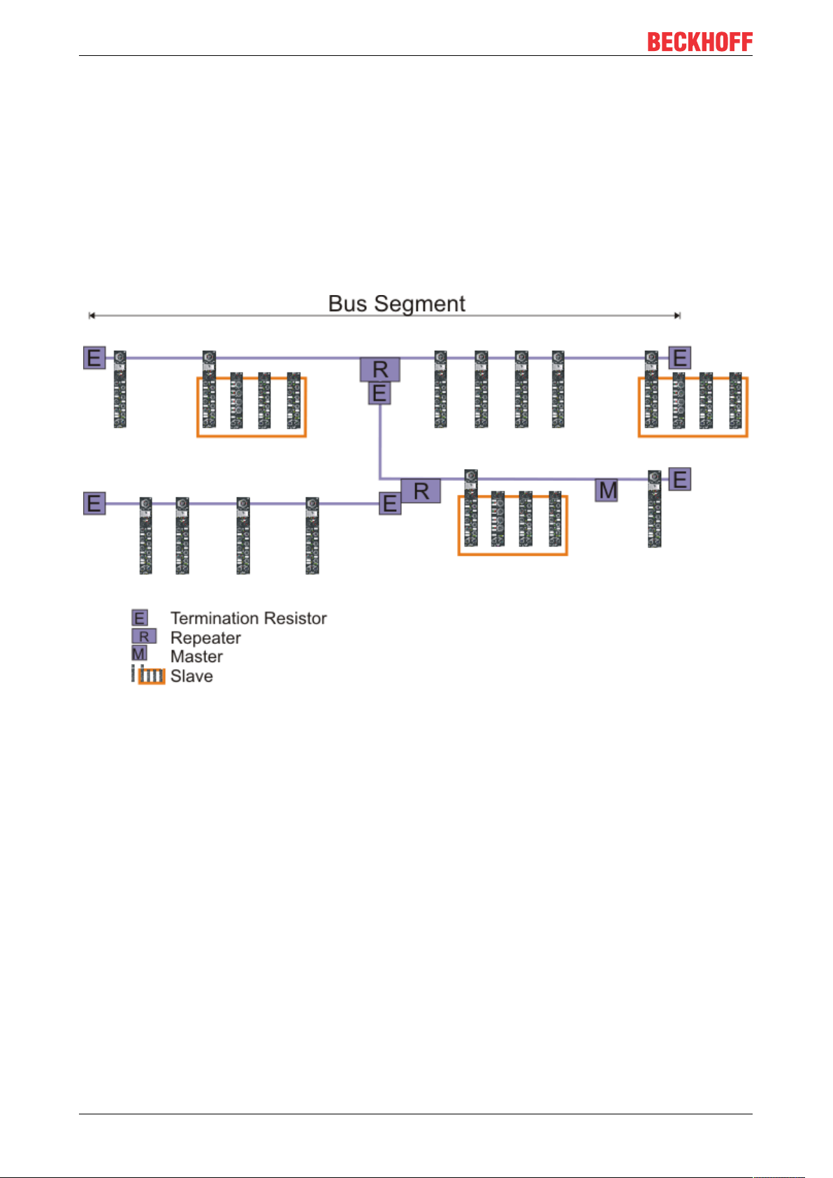
3.2 Topology
• A bus segment may consist of a maximum of 32 devices (including the repeaters).
• The maximum conductor length of a segment depends on the transmission speed in use and on the
quality of the bus cables being used.
• No more than 9 repeaters may be installed between two devices.
• Stubs are to be avoided, and are not permitted above 1.5 Mbaud.
• The maximum number of devices is 127
• Interrupting the supply voltage from cable ends by switching off the repeater/slave, or by pulling out the
plug, is not permitted.
Fig. 1: RS485 topology with 3 segments and 2 repeaters.
22 Version: 1.2.1
Page 23
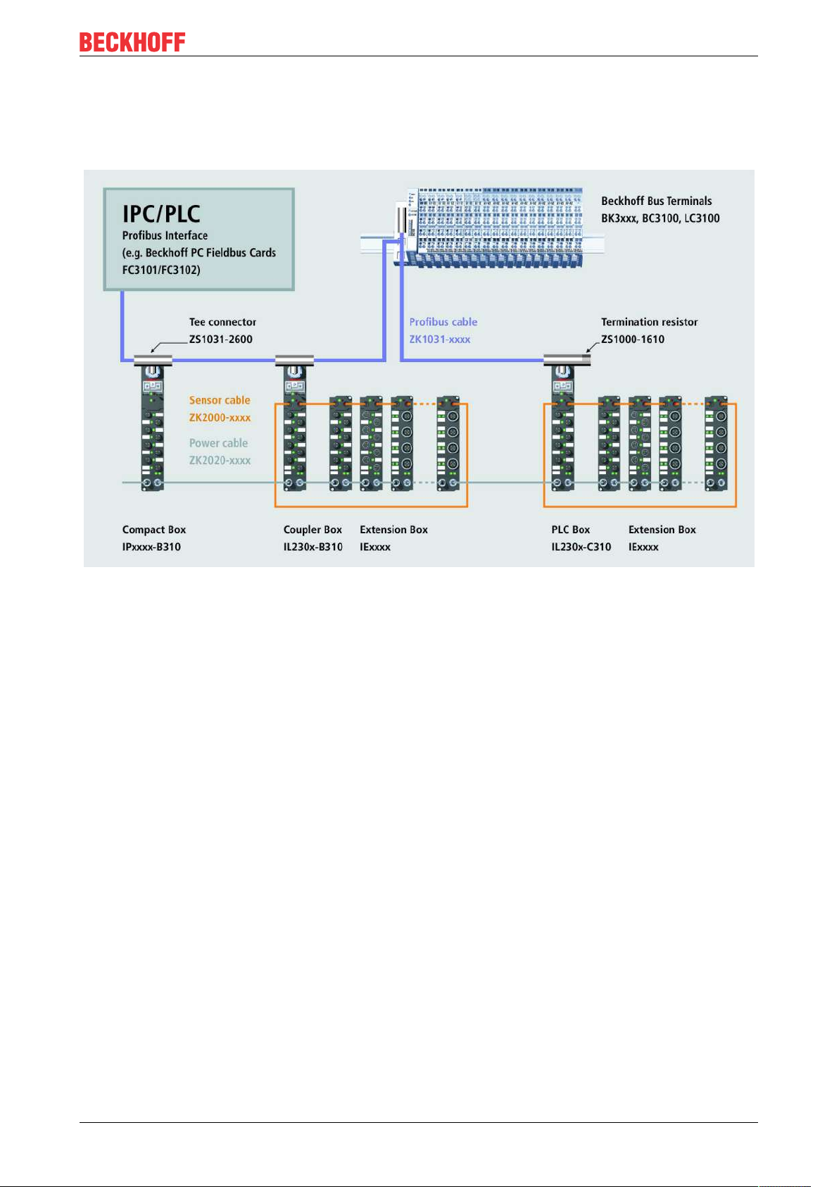
3.3 Application
Example of an PROFIBUS Application
Profibus
23Version: 1.2.1
Page 24

Profibus
3.4 PROFIBUS Cabling
3.4.1 PROFIBUS Cabling
Physical aspects of the data transmission are defined in the PROFIBUS standard (see PROFIBUS layer 1:
Physical Layer).
The types of area where a fieldbus system can be used is largely determined by the choice of the
transmission medium and the physical bus interface. In addition to the requirements for transmission
security, the expense and work involved in acquiring and installing the bus cable is of crucial significance.
The PROFIBUS standard therefore allows for a variety of implementations of the transmission technology
while retaining a uniform bus protocol.
Cable-based transmission
This version, which accords with the American EIA RS-485 standard, was specified as a basic version for
applications in production engineering, building management and drive technology. A twisted copper cable
with one pair of conductors is used. Depending on the intended application area (EMC aspects should be
considered) the screening may be omitted.
Two types of conductor are available, with differing maximum conductor lengths (see the RS-485 table).
Table4: RS485 - Fundamental properties
RS-485 transmission according to the Profibus standard
Network topology Linear bus, active bus terminator at both ends, stubs
are possible.
Medium Screened twisted cable, screening may be omitted,
depending upon the environmental conditions (EMC).
Number of stations 32 stations in each segment with no repeater. Can be
extended to 127 stations with repeater
Max. bus length without repeater 100 m at 12 MBit/s
200 m at 1500 KBit/s, up to 1.2 km at 93.75 KBit/s
Max. bus length with repeater Line amplifiers, or repeaters, can increase the bus
length up to 10 km. The number of repeaters possible
is at least 3, and, depending on the manufacturer,
may be up to 10.
Transmission speed (adjustable in steps) 9.6 kBit/s; 19.2 kBit/s; 93.75 kBit/s; 187.5 kBit/s; 500
kBit/s; 1500 kBit/s; 12 MBit/s
Plug connector 9-pin D-Sub connector for IP20
M12 round connector for IP65/67
Cabling for PROFIBUS DP and PROFIBUS FMS
Note the special requirements on the data cable for baud rates greater than 1.5 MBaud. The correct cable is
a basic requirement for correct operation of the bus system. If a simple 1.5 Mbaud cable is used, reflections
and excessive attenuation can lead to some surprising phenomena. It is possible, for instance, for a
connected PROFIBUS station not to achieve a connection, but for it to be included again when the
neighboring station is disconnected. Or there may be transmission errors when a specific bit pattern is
transmitted. The result of this can be that when the equipment is not operating, PROFIBUS works without
faults, but that there are apparently random bus errors after start-up. Reducing the baud rate (< 93,75
kBaud) corrects this faulty behavior.
If reducing the baud rate does not correct the error, then in many cases this can indicate a wiring fault. The
two data lines maybe crossed over at one or more connectors, or the termination resistors may not be active,
or they may be active at the wrong locations.
24 Version: 1.2.1
Page 25
Profibus
Pre-assembled cables from Beckhoff
Installation is made a great deal more straightforward if pre-assembled cables from Beckhoff are
used! Wiring errors are avoided, and commissioning is more rapidly completed. The Beckhoff range
includes fieldbus cables, power supply cables, sensor cables and accessories such as terminating
resistors and T-pieces. Connectors and cables for field assembly are nevertheless also available.
Termination resistors
In systems with more than two stations all devices are wired in parallel. It is essential that the bus
cables are terminated with resistors at the conductor ends in order to avoid reflections and associated transmission problems.
Distances
The bus cable is specified in EN 50170. This yields the following lengths for a bus segment.
Baud rate
in kbits/
sec
Cable
length in m
Stubs up to 1500 kbaud <6.6 m; at 12 Mbaud stub segments should not be used.
Bus segments
A bus segment consists of at most 32 devices. 126 devices are permitted in a PROFIBUS network.
Repeaters are required to refresh the signal in order to achieve this number. Each repeater is counted as
one device.
IP-Link is the subsidiary bus system for Fieldbus Boxes, whose topology is a ring structure. There is an IP
master in the coupler modules (IP230x-Bxxx or IP230x-Cxxx) to which up to 120 extension modules (IExxxx)
may be connected. The distance between two modules may not exceed 5 m. When planning and installing
the modules, remember that because of the ring structure the IP-Link master must be connected again to the
last module.
Installation guidelines
9.6 19.2 93.75 187.5 500 1500 12000
1200 1200 1200 1000 400 200 100
When assembling the modules and laying the cables, observe the technical guidelines provided by the
PROFIBUS User Organization (PROFIBUS Nutzerorganisation e.V.) for PROFIBUS DP/FMS
(seewww.profibus.com).
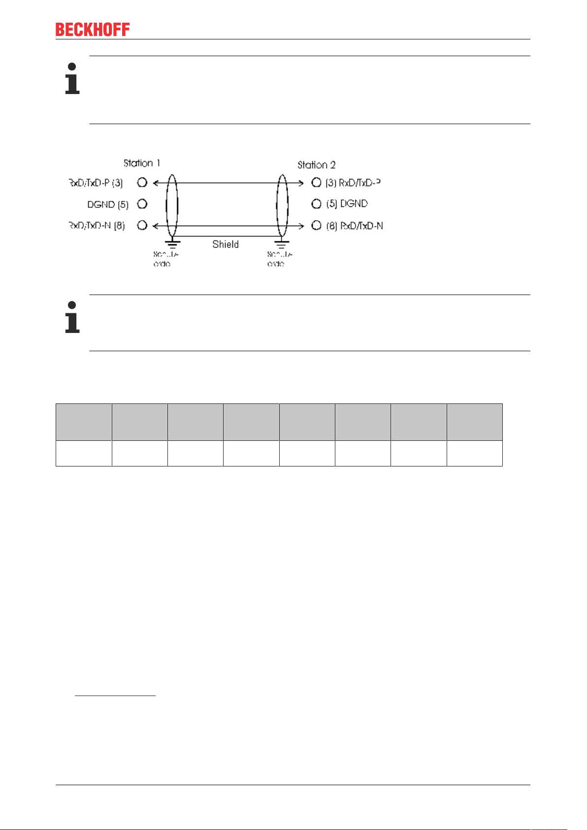
Checking the PROFIBUS wiring
A PROFIBUS cable (or a cable segment when using repeaters) can be checked with a few simple resistance
measurements. The cable should meanwhile be removed from all stations:
25Version: 1.2.1
Page 26

Profibus
1. Resistance between A and B at the start of the lead: approx. 110 Ohm
2. Resistance between A and B at the end of the lead: approx. 110 Ohm
3. Resistance between A at the start and A at the end of the lead: approx. 0 Ohm
4. Resistance between B at the start and B at the end of the lead: approx. 0 Ohm
5. Resistance between screen at the start and screen at the end of the lead: approx. 0 Ohm
If these measurements are successful, the cable is okay. If, in spite of this, bus malfunctions still occur, this
is usually a result of EMC interference. Observe the installation notes from the PROFIBUS User
Organization (www.profibus.com).
26 Version: 1.2.1
Page 27
Profibus
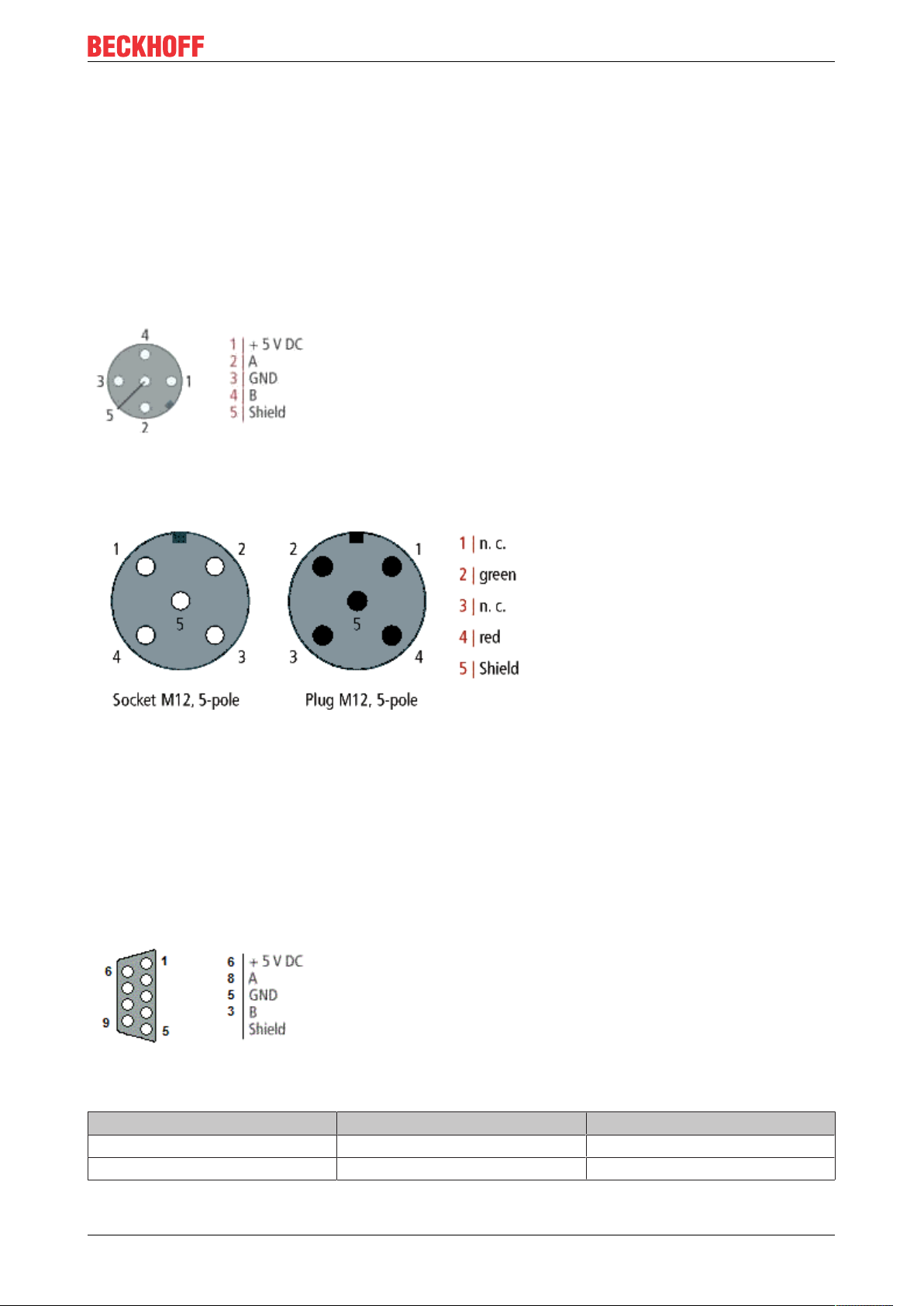
3.4.2 PROFIBUS Connection
M12 circular connector
The M12 socket is inverse coded, and has five pins. Pin 1 is 5 VDC and 3 is GND for the active termination
resistor. These must never be misused for other functions, as this can lead to destruction of the device.
Pin2 and pin4 are the PROFIBUS signals. These must never be swapped over, as this will prevent
communication. Pin5 is the shield, and this is capacitatively coupled to the Fieldbus Box chassis.
M12 socket pin assignment (-B310)
M12 socket/plug pin assignment (-B318)
Nine pole D-Sub
Pin 6 is 5 VDC und Pin 5 is GND for the active termination resistor. These must never be misused for other
functions, as this can lead to destruction of the device.
Pin3 and pin8 are the PROFIBUS signals. These must never be swapped over, as this will prevent
communication.
D-Sub socket pin assignment
PROFIBUS conductor colors
PROFIBUS conductors M12 D-Sub
B red Pin 4 Pin 3
A green Pin 2 Pin 8
27Version: 1.2.1
Page 28

Profibus
Connection of Fieldbus Box modules
The connection of the Fieldbus Box modules is done direct or via a T-piece (or Y-piece).
The B318 series does have a male and female connector, that means no external T-piece is required. The
supply voltage (+5VDC) for the termination resistor is only supplied via the female M12 connector. The
termination resistor ZS1000-1610 is only available with male connector.
Therefore the incoming PROFIBUS line should end in a female connector.
Two T-pieces are available:
• ZS1031-2600 with +5VDC on male and female connector for the termination resistor
• ZS1031-2610 with +5VDC only on the female connector
28 Version: 1.2.1
Page 29

Profibus
3.5 Protocol Description
3.5.1 Process Data
Once the parameter data and the configuration data has been correctly received and confirmed, the slave
goes into the Data_Exch state, which means that it exchanges data with the master. The master sends the
output data and the slave replies with the input data.
29Version: 1.2.1
Page 30

Profibus
3.5.2 Configuration Data (Cfg Data)
Following parameterization, the master sends a configuration telegram to the slave. The configuration
telegram causes the slave to check the configuration that has been sent by the master.
Structure of configuration byte:
Bit 0..3 Length of the data
00 = 1 byte/Word
15 = 16 byte/Word
Bit 4..5 Input/Output
00 = special identification format
01 = input
10 = output
11 = input/output
Bit 6 Byte/Word
0 = byte
1 = Word
Bit 7 Consistency
0 = consistency over byte/word
1 = consistency over the entire length
30 Version: 1.2.1
Page 31

Profibus
3.5.3 Activating the DPV1 Functions
The DPV1 functions can be activated in the parameter data (GSD, GSE). These functions are deactivated in
the default setting. (Prm. byte 0 bit 15=1 activated, bit 15 =0 [default] deactivated)
DPV1 Functions
The IP/IL modules and the EconomyPlusBus Coupler (BK3120) support the following functions in the DPV1
services. The maximum length of the DP-V1 services is 48 bytes.
IP/IL configuration (IP-Link only)
The configuration of the extension modules can be read from the IP-Link coupler module. A word (of 16 bits)
is transferred for each connected extension module (IExxxx). This contains the type of the module in the
case of the analog modules, and the size and type of the digital extension modules.
Bit Value: description of the digital module
0-1 If bit 4 = 0: number of 2-bit outputs, if bit 4 = 1:
number of 8-bit outputs
2-3 If bit 4 = 0: number of 2-bit inputs, if bit 4 = 1: number
of 8-bit inputs
4 0: Bit size 2, 1: bit size 8
5-6 0: Standard: Inputs and outputs do not have the
same starting address
1: Combined I/O: Inputs and outputs to have the
same starting address
2: Reserved
3: Outputs with diagnostics
7-15 always 0
The module configuration can be read with the following DPV1 parameters: (KS2000 Table 9) The modules
are entered in the sequence in which they are connected at the IP-Link.
Slot number Index Byte Description
0 9 0-1 Bus Coupler/module
identifier
0 9 2-3 Module -1
0 9 ... ...
0 9 46-47 Module 23
0 10 0-1 Module 24
0 10 ... ...
0 10 46-47 Module 47
0 11 0-1 Module 48
0 ... ... ...
0 13 46-47 Module 95
0 14 0-1 Module 96
0 14 ... ...
0 14 30-31 Module 119
This information can also be written by DPV1. If the written configuration does not agree with the
configuration contained in the table, a DPV1 error message is received.
Module Register
The register of extension modules can be read or written:
31Version: 1.2.1
Page 32

Profibus
Slot number Index Description
1 0 Register 0 of module 1, channel 1
1 ... ...
1 63 Register 63 of module 1, channel 1
1 64 Register 0 of module 1, channel 2
1 ... ...
1 255 Register 63 of module 1, channel 4
2 0 Register 0 of module 2, channel 1
(from here only for IP-Link)
... ... ...
255 255 Register 63 of module 255,
channel 4
IP-Link Reset
The IP-Link reset can be activated with the following DPV1 parameters: (Following an interruption of the IPLink and its correction, the IP-Link can be started again)
Slot number Index Byte Value
0 99 0 2
0 99 1 1
0 99 2 0
0 99 3 0
Measuring the IP-Link cycle time
Starting and stopping the IP-Link cycle time is set by the following DPV1 parameters:
Slot number Index Byte Value
0 99 0 4
0 99 1 1
0 99 2-3 0: Stop, >0: Start
The cycle time can be read, and to reset the values it can also be written with the following DPV1 parameter:
Slot number Index Byte Description
0 98 0-1 Minimum IP-Link cycle
time (in µs)
0 98 2-3 Maximum IP-Link cycle
time (in µs)
0 98 4-5 Current IP-Link cycle time
(in µs)
0 98 6-7 Mean IP-Link cycle time
(in µs)
Manufacturer’s setting
The following DPV1 parameters must be written in order to adopt the manufacturer's settings:
Slot number Index Byte Value
0 99 0 1
0 99 1 4
0 99 2 0
0 99 3 0
32 Version: 1.2.1
Page 33

Profibus
3.6 Description of the Parameter Data
3.6.1 General
3.6.1.1 Parameterisation Telegram
The Set_Prm service can be used to transfer not only the parameters described in the Profibus DP standard,
but also manufacturer-specific operating parameters (User_Prm_Data). This is transmitted once from the
master to the slave while the connection is being established. Generally speaking, the configuration tool for
the DP master can read those operating parameters for the Fieldbus Box that can be set out of the GSD file,
and can display them in plain text. The following manufacturer-specific operating parameters can be set for
the Fieldbus Box:
Standard functionality Modules that support the functions
DPV1 Services IPxxxx-B310, IL230x-B310, IL230x-C310
Reset in the event of an IP-Link error IL230x-B310, IL230x-C310
Process data format [}37]
Synchronisation of the DP-/IP-Link cycle [}33]
Reaction to Profibus errors [}39]
Reaction to IP-Link errors IL230x-B310, IL230x-C310
IPxxxx-B310, IL230x-B310, IL230x-C310
IL230x-B310, IL230x-C310
IPxxxx-B310, IL230x-B310, IL230x-C310
Expert functionality
2 byte PLC interface
IP-Link-Cycle-Counter
Also see about this
2 Reaction to IP-Link Errors [}40]
3.6.1.2 Updating the Process Image
Function
The K-Bus cycle (IP-Link) can be started cyclically (process image updating: free running ) or synchronously,
with receipt of the DP-Data_Exchange telegram (process image updating: synchronous with cycles). If
updating the process image is set to be synchronous with cycles, then the K-Bus cycle is started after receipt
of the Data_Exchange telegram; otherwise the K-Bus cycle (IP-Link) is started independently of the
Data_Exchange telegrams. The free running and synchronous procedures for updating of the process image
are represented schematically below.
33Version: 1.2.1
Page 34

Profibus
Free Run
Figure: Free-Run-Mode
Synchronous
Figure: The principle of updating the process image
Byte Bit Description
9 6 Updating of the process image
Note
Special attention must be paid to the running and reaction times of the whole system when parameterising the process image update function.
Fast- Free- Run
In fast-free-run mode, the priority of the K-Bus/IP-Link is set higher. This activates the internal bus more
frequently. This implies that the interfaces (such as KS2000 or DPV-1) are not dealt with so quickly. Fastfree-run mode is only permitted in asynchronous operation.
34 Version: 1.2.1
Page 35

Figure: Fast-Free-Mode
Byte Bit Description
9 4 Fast-Free-Run-Mode
Profibus
A certain running time is required to transmit the signals from the inputs to the controller and from the
controller to the outputs. It is composed of a number of elements:
• Transmission from the controller to the Profibus master
• Transmission via Profibus (see Profibus reaction time [}35]) and
• Transmission from the Profibus box to the outputs (see K-Bus reaction time [}36]) / (see IP-Link cycle
time [}37])
The opposite sequence applies to the return journey.
Please see the data provided by the Profibus master manufacturer for the reaction time from the controller to
the Profibus master. The times a comparatively short, and do not usually have to be taken into account.
Profibus reaction time
Profibus reaction time
The reaction time tDP on the Profibus is made up as follows. The constants A, B and
depend on the
TBYTE
baud rate.
t =
DP
Constant A
+ (constant B + (number of I/O
bytes x T
BYTE
))
+ (constant B + (number of I/O
bytes x T
BYTE
))
+ (constant B + (number of I/O
bytes x T
BYTE
))
+ (constant B + (number of I/O
bytes x T
BYTE
))
[Slave 1]
[Slave 2]
[Slave 3]
[Slave n]
35Version: 1.2.1
Page 36

Profibus
Baud Rate Constant A (in ms) Constant B (in ms) TBYTE (in ms)
9.6 kBaud 64.5 25.6 1.15
19.2 kBaud 32.3 12.8 0.573
93.75 kBaud 6.6 2.62 0.118
187.5 kBaud 3.3 1.31 0.059
500 kBaud 1.6 0.49 0.022
1.5 MBaud 0.67 0.164 0.00733
3 MBaud 0.436 0.085 0.00367
6 MBaud 0.27 0.044 0.00183
12 MBaud 0.191 0.024 0.00092
K-Bus reaction time (K-Bus)
K-Bus reaction time (K-Bus)
The reaction time on the K-Bus (internal bus of the Compact Box) is determined by the shifting and saving of
the data. The following table contains measured values for typical structures. It is possible to scale the
calculation up for larger numbers.
Compact Box (numbers are for channels) Running time on the K-
bus
Digital OUT Digital IN Analog IN/OUT T_cycle (µs)
4 0 0 150
8 0 0 170
12 0 0 170
16 0 0 200
20 0 0 200
24 0 0 220
28 0 0 220
32 0 0 245
0 4 0 150
0 8 0 180
0 12 0 180
0 16 0 200
0 20 0 200
0 24 0 230
0 28 0 230
0 32 0 250
4 4 0 170
8 8 0 195
12 12 0 220
16 16 0 250
20 20 0 275
24 24 0 300
28 28 0 325
32 32 0 350
4 4 1 630
4 4 2 700
36 Version: 1.2.1
Page 37

Profibus
Note
For physical reasons, the K-Bus cycle is always at least about 90 µs. This means that the running or
cycle time of the whole system, and in particular the cycle time for the PLC task, must be greater
than the running time of the K-Bus cycle. If this is not the case, unstable conditions can arise in the
input and output terminals of the PROFIBUS slave.
IP-Link reaction time
IP-Link reaction time
The reaction time on the IP-Link is determined by the shifting and saving of the data. The following table
contains measured values for typical structures. It is possible to scale the calculation up for larger numbers.
Extension Boxes added to Coupler Boxes Running time on the IP-
Link
Digital OUT (bits) Digital IN (bits) Analog IN/OUT (chan-
nels)
24 16 0 420
48 16 0 450
24 16 4 1500
48 16 16 2360
48 16 28 3500
48 16 40 4000
T_cycle (µs)
The settings for the Process image updating function are found in byte 9 of the User_Prm_Data (default
settings are printed bold):
Bit no. Description is supported by
Bit 6 Updating of the process image
0: synchronous with cycle
1: free running
In TwinCAT the settings for the PROFIBUS synchronisation DP/K-Bus cycle can be transferred with
ADSRead and ADSWrite (ADS: Automation Device Specification). For this purpose they should be activated
in the User_Prm_Data.
The settings for the Process updating function are found in the TwinCAT System Manager on the PrmData
tab for the corresponding Busbox.
IP10xx, IP15xx; IP20xx, IP23xx,
IP25xx, IP31xx, IP41xx, IP50xx,
IP51xx, IP60xx
3.6.1.3 Auto-configuration data format
This parameter sets the representation format for the complex terminals. You may choose between Intel
[}38] and Motorola [}38] formats:
37Version: 1.2.1
Page 38

Profibus
• Under the Intel format, the less significant byte (low byte) of a data word is located at the lowest
address offset of the memory location.
• Under the Motorola format, the more significant byte (high byte) of a data word is located at the lowest
address offset of the memory location.
If you choose the Motorola format for digital terminals, then the two bytes transmitted, for instance, for 16
sequential digital channels, the high byte and the low byte will be swapped.
Representation in Intel format
Intel format
Byte 0 Byte 1 Byte 2 Byte 3 Byte 4 Byte 5
Word 0 Word 2 Word 4
Word 1 Word 3
In terms of bit addresses, the result is:
High byte Low byte
1.7 1.6 1.5 1.4 1.3 1.2 1.1 1.0 0.7 0.6 0.5 0.4 0.3 0.2 0.1 0.0
Byte 1 Byte 0
Representation in Motorola format
Motorola format
Byte 1 Byte 0 Byte 3 Byte 2 Byte 5 Byte 4
Word 0 Word 2 Word 4
In terms of bit addresses, the result is:
High byte Low byte
0.7 0.6 0.5 0.4 0.3 0.2 0.1 0.0 1.7 1.6 1.5 1.4 1.3 1.2 1.1 1.0
Byte 0 Byte 1
Settings
The settings for the Data format auto-configuration function are found in byte 9 of the User_Prm_Data
(default settings are printed bold):
Bit no. Description is supported by
Bit 3 Auto-configuration data format
0: Intel
1: Motorola
IP15xx, IP25xx, IP31xx, IP41xx,
IP50xx, IP51xx, IP60xx
In TwinCAT the settings for the Data format auto-configuration can be transferred with ADSRead and
ADSWrite (ADS: Automation Device Specification). For this purpose they should be activated in the
User_Prm_Data.
The settings for the Data format auto-configuration function are found in the TwinCAT System Manager on
the PrmData tab for the corresponding Busbox.
38 Version: 1.2.1
Page 39

Profibus
3.6.1.4 Reaction to PROFIBUS errors
The reaction to a PROFIBUS error (e.g. the plug is pulled out, STOP of the DP master, etc.) can be set. The
possible reactions are:
• Stopping the K-Bus
• Resetting the outputs to 0
• Retaining the current output states
Note
In the Cycle is stopped setting, the signal states of the output terminals are identical to those under
the Outputs become 0 setting.
The settings for the Reaction to Profibus error function are found in byte 10 of the User_Prm_Data (default
settings are printed bold):
Bit no. Description is supported by
Bits 0/1 Reaction to Profibus errors
0: Cycle is stopped
1: Outputs become 0
2: Outputs remain the same
In TwinCAT the settings for the Reaction to PROFIBUSerror can be transferred with ADSRead and
ADSWrite (ADS: Automation Device Specification). For this purpose they should be activated in the
User_Prm_Data.
The settings for the Reaction to PROFIBUSerror function are found in the TwinCAT System Manager on the
"PrmData" tab for the corresponding Bus Coupler.
IP10xx, IP15xx, IP20xx, IP23xx,
IP25xx, IP31xx, IP41xx, IP50xx,
IP51xx, IP60xx
39Version: 1.2.1
Page 40

Profibus
3.6.1.5 Reaction to IP-Link Errors
The error reaction can be set for an IP-Link error (such as pulling out the plug). The possible reactions are:
• Data exchange is stopped.
• Profibus inputs become 0
• Profibus inputs are retained unchanged
The settings for the reaction to Profibus error function are found in byte 10 of the User_Prm_Data (default
settings are printed bold):
Byte Bit Description is supported by
10 2, 3 Reaction to Profibus
errors
0: Data exchange is
aborted
1: Inputs become 0
2: Inputs remain
unchanged
In TwinCAT the settings for the Reaction to IP-Link error can be transferred with ADSRead and ADSWrite
(ADS: Automation Device Specification). For this purpose they should be activated in the
User_Prm_Data.
IL230x-B3xx
The settings for the Reaction to IP-Link error function are found in the TwinCAT System Manager on the
"PrmData" tab for the corresponding Bus Coupler.
40 Version: 1.2.1
Page 41

Profibus
3.6.2 Parameter Data
3.6.2.1 IPxxxx-B31x - User Parameters
Data format
Data format [}37]
Auto configuration (only applies to all complex devices, not necessary for digital devices)
Complex terminal data can be represented in either Intel or Motorola format, although controllers generally
expect the data to be in Motorola format.
Example:
In Motorola format, an analog value from an IP3312-Bxxx is shown as 0x0016. In Intel format, the high and
low bytes are exchanged, yielding 0x1600.
Updating of the process image
Updating of the process image [}33]
• Synchronous with the cycle means that the data are triggered in synchronism with the PROFIBUS
image. If a PROFIBUS telegram reaches the slave, the slave copies the data into the ASIC after the
answer telegram has been sent. The outputs are written immediately.
• Free running means that the data is fetched and copied into the ASIC, and that this is repeated
continuously.
Free running can be used when it is necessary to transfer the input data as fast as possible to the controller.
The disadvantage of this is that the data is not free from jitter. If fast outputs are needed, or if it is necessary
for the inputs to be jitter-free (e.g. for fast controllers) then cyclic transmission should be selected.
Reaction to PROFIBUS errors
Reaction to PROFIBUS errors [}39]
• Cycle is stopped. The internal data process is stopped, and the watchdog (WD) for the channels
(usually 100 ms) triggers.
• Outputs become 0. Zero is written to all the outputs in a defined manner.
• Outputs remain the same. The most recently received PROFIBUS telegram and its output data is
retained. A switched output, e.g. at a IP4112 with 12 ms, is retained as long as it takes to reconstruct
the PROFIBUS cycle and a new value is transmitted via the process data.
3.6.2.2 User parameters for the Coupler Box Modules (IL230x-B31x)
DPV1 Services
The DPV1 services can be activated or deactivated here. Default: Not active (see DPV1 services [}31]).
Behavior in the event of an IP-Link error
The IP-Link can start up again of its own accord once an IP-Link error (such as a cable break) has been
corrected. Warning: PROFIBUS data communication begins once more, and outputs are written again. The
user must ensure that undesirable outputs are not written in such a case. Default: Manual reset.
41Version: 1.2.1
Page 42

Profibus
Fieldbus Box Diagnostics
The diagnostic data can be activated here. Default: Not active (see Diagnostics for the Compact Box or
Diagnostics for the Coupler Box).
Byte 7, bit 1:
- True activated
- False deactivated
Data format
Data that is 2 bytes in size can be transmitted either in Intel or in Motorola format. The high byte and the low
byte are swapped. Default: Motorola.
Updating process data
The IP-Link can be triggered in synchronism with PROFIBUS , or can be allowed to run free. Default: Free
running (see Updating process data [}33]).
Reaction to PROFIBUS errors
This describes the behavior of the slave in the presence of a PROFIBUS error (such as a faulty cable).
Default: The IP-Link cycle is abandoned
• The IP-Link cycle is abandoned, which means that the extension module's watchdog will trigger after
100 ms, and the outputs will be switched into a safe condition
• The IP-Link master writes a 0 to the outputs
• The outputs remain frozen in their last state
Reaction to IP-Link errors
This describes the behavior of the slave in the presence of an IP-Link error (such as a faulty cable). Default:
DataExchange is abandoned
• DataExchange is abandoned, which means that the slave halts the PROFIBUS communication.
• DP inputs become 0 - A zero is written to the inputs
• DP inputs are retained - The inputs retain their most recent valid state
IL/IE Byte Alignment )
1
This allows all the IL/IE23xx modules with 4 bit input/outputs to be rounded to a byte.
Byte 10 bit 5 Default "0"
1 All the IE23xx modules are mapped with eight bits. In fact the inputs from 0..3 are sufficient (4..7 are not
used), as are the outputs from bits 4..7 (0..3 are not used).
0 All IE23xx modules are mapped with four inputs and four outputs (default)
)1Firmware update is possible for the IL modules from software version 1 D:xxxx1xxx.
3.6.2.3 IL230x-C3xx - User Parameters
Copy the fieldbus and IP-Link status into the allocated flags area
Byte 13, bit 5
1 is copied into the region %MB408-411 (default)
0 is not copied into the region %MB408-411
Saving the modules when creating the boot project
Byte 13, bit 6
1 is checked (default)
0 is not checked
42 Version: 1.2.1
Page 43

Profibus
Copy the cycle tick counter into the allocated flags area
Byte 12, bit 0
1 is copied into the region %MB404-407 (default)
0 is not copied into the region %MB404-407
Reaction to Breakpoints
Byte 12, bit 1
1 Outputs are written as zero
0 Outputs remain unchanged (default)
3.6.2.4 Module-specific Parameter Data
User parameters for Compact Box Modules (IP3xxx-B310)
The module-specific parameter data can be used as from version D.xxxx3xxx.
Your software can be updated if the hardware version is D.xxxxx8xx or above. Please contact Support for
this purpose.
IP3102-B310
- Overflow offset (can be set individually for each channel)
- Set and activate limit values (can be set individually for each channel)
IP3112-B310
- Overflow offset (can be set individually for each channel)
- Set and activate limit values(can be set individually for each channel)
- Input current range(can be set individually for each channel): 0...20mAor4...20mA
IP3202-B310
- Set PT elements(can be set individually for each channel)
- Two/three/four wire connection(can be set individually for each channel)
- Over-range protection(can be set individually for each channel)
IP3312-B310
- Adjust thermocouple (can be set individually for each channel)
- Cold junction compensation(can be set individually for each channel):
- Over-range protection(can be set individually for each channel)
User parameters for Compact Box Modules IP4xxx-B310
The module-specific parameter data can be used as from version D.xxxx3xxx.
Your software can be updated if the hardware version is D.xxxxx8xx or above. Please contact Support for
this purpose.
IP4112-B310
- Output current range (can only be set jointly for all channels): 0...20mAor4...20mA
- Watchdog(can be set individually for each channel)
IP4132-B310
- Watchdog (can be set individually for each channel)
43Version: 1.2.1
Page 44

Parameterization and commissioning
4 Parameterization and commissioning
4.1 Start-up behavior of the Fieldbus Box
After power up, the Fieldbus Box checks its state, configures the IP-Link (if present) and refers to the
extension modules to create a structure list. If the Fieldbus Box contains a decentralized controller (IL230xC310) the local PLC is started once the structure list has successfully been created.
The I/O LEDs illuminate and flash as the module starts up. If there are no errors, the I/O LEDs should stop
flashing within about 2-3 seconds. If there is an error, then the LED that flashes will depend on the type of
that error (see Diagnostic LEDs).
44 Version: 1.2.1
Page 45

Parameterization and commissioning
4.2 Addressing
The Profibus address must be set using the two rotary selection switches behind the transparent cover. The
default setting is 11. Any address is permitted, but each address may only be used once within the network.
The address is changed while the Fieldbus Box is switched off. To do this, unscrew the cover and use a
screwdriver to move the switches to the desired position. Make sure that the switches engage properly. The
switch on the left represents the tens, while that on the right represents the units. The change in address is
active as soon as the device is switched on.
Fieldbus Box
Example
You want to set address 34.
Left-hand rotary selection switch: 3
Right hand rotary selection switch: 4
Bus Coupler
The bottom switch S311 represents the tens, while S310 the upper one represents the units.
45Version: 1.2.1
Page 46

Parameterization and commissioning
4.3 Baud Rate
The Fieldbus Box for PROFIBUS has automatic baud rate detection. As soon as the electrical power is
switched on, the Fieldbus Box searches for the baud rate that is being used, and stores it for as long as the
supply voltage is present.
Note
If you change the baud rate of your PROFIBUS master, you must switch the Fieldbus Box off and
on again once.
Distances
The bus cable is specified in EN 50170. This yields the following lengths for a bus segment.
Baud rate
in kbits/
sec
Cable
length in m
Stubs up to 1500 kbaud <6.6 m; at 12 Mbaud stub segments should not be used.
9.6 19.2 93.75 187.5 500 1500 12000
1200 1200 1200 1000 400 200 100
46 Version: 1.2.1
Page 47

Parameterization and commissioning
4.4 Configuration
4.4.1 Configuration Data (Cfg Data)
Cfg Data [}30]
The PROFIBUS coupler creates a data area with input and output bytes (Peripheral data in the process
image). The assignment of the channels in the Bus Terminals/Modules and the process image is carried out
by the Bus Coupler/Fieldbus Box.
The PROFIBUS master exchanges a continuous input and output data block with each Bus Coupler/Fieldbus
Box. The assignments of the bytes from this data block to the addresses in the process image is carried out
by the master. In the PLC master of the IM308-C the COM PROFIBUS software supports the configuration,
and in the IM308-B the COMET200 software does this job. For other PROFIBUS Masters, the appropriate
tools from the manufacturer are to be used.
Note
A configuration software is utilized to configure the PROFIBUS master. Different programs are
used, depending on the manufacturer. These programs generally use the GSD file in order to be
able to set the slave parameters optimally. The type file is frequently used for Siemens PROFIBUS
masters; only more recent versions of the Siemens software also work with the GSD file. Copy the
necessary files into the appropriate directories before you start the master configuration software.
The Beckhoff GSD and type files are available for download from www.beckhoff.com.
After being switched on, the Bus Coupler or Fieldbus Box determine the configuration of the connected input/
output terminals. The assignment of the physical slots for the input/output channels and the addresses in the
process image is carried out automatically by the Bus Coupler. A distinction is made here between bitoriented (digital) and byte-oriented (analog or complex) signal processing. The Bus Coupler first writes the
byte oriented Bus Terminals into the process image, followed by the bit oriented terminals.
Table5: Bus Terminals
Byte oriented Bus Terminals Bit oriented Bus Terminals
KL1501, KL2502,
KL3xxx, KL4xxx,
KL5xxx, KL6xxx
Table6: Fieldbus Boxes
Byte oriented Fieldbus Boxes Bit oriented Fieldbus Boxes
IP/IE1501, IP/IE25x2, IE2808
IP/IE3xx2, IP/IE4xx2,
IP/IE5xx2, IP/IE6xx2
When configuring the master, it must be borne in mind that all the byte oriented Bus Terminals and Fieldbus
Boxes must first be entered in the sequence in which they are physically inserted. No distinction is made
here between input terminals and output terminals. The bit-oriented bus terminals come next. These are
rounded up to a full byte, so that 12 digital signals, corresponding to 12 bits, are rounded up to two bytes.
The remaining four bits are automatically filled with zeros. The GSD file contains 8/16/32, up to 1 word,
digital inputs and/or outputs for the bit-oriented terminals.
KL10xx, KL11xx, KL12xx, KL17xx,
KL20xx, KL21xx, KL22xx, KL26xx,
KL9110, KL9160, KL9210, KL9260
IP/IE1xxx, IPIE2xxx
For the byte oriented Bus Terminals/Modules, only the initial identification plus the "placeholder" is given
(e.g. KL3xxx or IP3xxx-B310) rather than the terminal name itself. All of these terminals are equal in the size
in the process image. After this, the number of channels can be specified. This is useful if it is desired to
assign different addresses in the PLC to the terminal channels.
47Version: 1.2.1
Page 48

Parameterization and commissioning
Number of bits (input, output channels) Meaning in the process image
16 In only user data
24 In / 8 Out User data plus control and status (only in the KL3xxx)
8 In / 24 Out User data plus control and status (only in the KL4xxx)
24 In / 24 Out Full process image
4.4.1.1 Example - Siemens S5
4.4.1.1.1 Configuration - Siemens S5 Controller with COM Profibus
Begins by copying the *.gsd files into the GSD directory of your COM Profibus software. You will find the
GSD on the Beckhoff website. Your next step is to read the files into the COM Profibus software.
After this, you will find the files under "DP-Slave/I/O/...
48 Version: 1.2.1
Page 49

Parameterization and commissioning
Now select the appropriate slave.
4.4.1.1.2 Configuration: IP41xx-B310
With the IP41xx-B310 you have the option of choosing between two different mapping types:
• Compact mapping simply describes the output user data, i.e. four output words (16 bits for each
channel).
• Complex mapping additionally has a control and status byte; in the IP41xx.B310 this can only be used
for register communication. Mapping 4 x 3 bytes input and output.
The settings can only be made for an entire module (not for individual channels).
An example of compact mapping:
49Version: 1.2.1
Page 50

Parameterization and commissioning
An example of complex mapping:
50 Version: 1.2.1
Page 51

Parameterization and commissioning
You can also change the user parameters (see Configuration Files [}47]).
51Version: 1.2.1
Page 52

Parameterization and commissioning
4.4.1.2 Example - Siemens S7
4.4.1.2.1 Configuration - Siemens S7 Controller with COM Profibus
Inserting the images
In order to assign an image to the devices in the Siemens software, they must be copied into the
Step7\S7Data\ncbmp directory.
IPxxxx-B310 IL230x-B310/C310
Inserting the GSD files
• Go to Extras\Install new GSD in the hardware catalog for your Step7.
• Select the directory in which the Beckhoff GSD is located, and import the files.
• You will then find them in the hardware catalog under Profibus DP\Other field devices\I/O.
4.4.1.2.2 Configuration - IL230x-B31x
Parameter data for the IL230x-B31x
Settings
52 Version: 1.2.1
Page 53

Parameterization and commissioning
Parameter data Denomination
DPV1-Services
IP-Link-Error Reaction to IP-Link
IP Module diagnosis
Data format
Updating of process image
Reaction on DP-Error
IP-Link-Error-Reaction IP-Link error reaction
IL/IE23xx Byte-Align Mapping of the 4 DI / DO (IL/IE23xx) modules
Configuration of the IL230x-B31x module with only digital inputs and outputs
Example:
1 x IL2301-B310
4 x IE1001
5 x IE2001
The sum total of digital bytes must be added together and entered.
DPV1 Services [}31]
PROFIBUS diagnosis [}71]
Data format [}37]
K-Bus update [}33]
Reaction to fieldbus error [}39]
53Version: 1.2.1
Page 54

Parameterization and commissioning
Example:
1 x IL2301-B310
4 x IE1001
5 x IE2001
The same configuration can also be created as follows. The advantage of this method is that each byte
receives a different address, and if a digital extension module is inserted, the addresses of the other
modules are not shifted. A maximum of 64 modules can be inserted (slots 0-63)
Configuration of the IL230x-B31x module with complex and digital inputs and outputs
Complex modules are the first to be mapped into the process image. For this reason all the complex
modules must be entered in the sequence in which they are attached to the IP-Link. Finally the digital signals
must be rounded up to a byte.
54 Version: 1.2.1
Page 55

Example:
1 x IL2301-B310
1 x IE3102 compact mapping
Parameterization and commissioning
Example:
1 x IL2301-B310
1 x IE3102 complex mapping
55Version: 1.2.1
Page 56

Parameterization and commissioning
4.4.2 Configuration of the complex Modules
4.4.2.1 Register Communication
4.4.2.1.1 General Register Description
Different operating modes or functionalities may be set for the complex modules. The General Description of
Registers explains those register contents that are the same for all complex modules. The module-specific
registers are explained in the following section.
Access to the module's internal registers is described in the section on Register Communication.
General Description of Registers
Complex modules that possess a processor are able to exchange data bi-directionally with the higher-level
controller. These modules are referred to below as intelligent modules. These include the analog inputs
(0-10 V, -10-10 V, 0-20 mA, 4-20 mA), the analog outputs (0-10 V, -10-10 V, 0-20 mA, 4-20 mA), the serial
interface terminals (RS485, RS232, TTY, data exchange terminals), counter terminals, encoder interface and
SSI interface terminals, PWM terminals and all the modules that can be parameterized.
The main features of the internal data structure are the same for all the intelligent modules. This data area is
organized as words, and includes 64 memory locations. The important data and the parameters of the
module can be read and set through this structure. It is also possible for functions to be called by means of
corresponding parameters. Each logical channel in an intelligent module has such a structure (so a 4channel analog module has 4 sets of registers).
56 Version: 1.2.1
Page 57

Parameterization and commissioning
This structure is divided into the following areas:
Range Address
Process variables 0-7
Type register 8-15
Manufacturer parameters 16-30
User parameters 31-47
Extended user region 48-63
Registers R0-R7 (in the terminal's internal RAM)
The process variables can be used in addition to the actual process image. Their function is specific to the
terminal.
R0-R5
The function of these registers depends on the type of terminal.
R6
Diagnostic register. The diagnostic register can contain additional diagnostic information. Parity errors, for
instance, that occur in serial interface terminals during data transmission are indicated here.
R7
Command register
- High-Byte_Write = function parameter
- Low-Byte_Write = function number
- High-Byte_Read = function result
- Low-Byte_Read = function number
Registers R8-R15 (in the terminal's internal ROM)
The type and system parameters are hard programmed by the manufacturer, and the user can read them
but cannot change them.
R8
Fieldbus Box type: The Fieldbus Box type in register R8 is needed to identify the Fieldbus Box.
R9
Software version x.y.: The software version can be read as a string of ASCII characters.
R10
Data length: R10 contains the number of multiplexed shift registers and their length in bits. The Bus Coupler
sees this structure.
R11
Signal channels: Related to R10, this contains the number of channels that are logically present. Thus for
example a shift register that is physically present can perfectly well consist of several signal channels.
R12
Minimum data length: The particular byte contains the minimum data length for a channel that is to be
transferred. If the MSB is set, the control/status byte is not absolutely necessary for the terminal's function,
and if the Bus Coupler is appropriately configured it is not transferred to the controller. The information is
57Version: 1.2.1
Page 58

Parameterization and commissioning
located
- in the high byte of an output module
- in the low byte of an input module
R13
Data type register
Data type register Description
0x00 Terminal with no valid data type
0x01 Byte array
0x02 Structure 1 byte n bytes
0x03 Word array
0x04 Structure 1 byte n words
0x05 Double word array
0x06 Structure 1 byte n double words
0x07 Structure 1 byte 1 word
0x08 Structure 1 byte 1 double word
0x11 Byte array with variable logical channel length
0x12 Structure 1 byte n bytes with variable logical channel
length (e.g. 60xx)
0x13 Word array with variable logical channel length
0x14 Structure 1 byte n words with variable logical channel
length
0x15 Double word array with variable logical channel
length
0x16 Structure 1 byte n double words with variable logical
channel length
R14
reserved
R15
Alignment bits (RAM): The analog terminal is placed on a byte boundary in the K-Bus with the alignment bits.
Registers R16-R30 (manufacturer's parameters, serial EEPROM)
The manufacturer parameters are specific for each type of terminal. They are programmed by the
manufacturer, but can also be modified by the controller. The manufacturer parameters are stored in a serial
EEPROM in the terminal, and are retained in the event of voltage drop-out. These registers can only be
altered after a code-word has been set in R31.
Registers R31-R47 (application parameters, serial EEPROM)
The application parameters are specific for each type of terminal. They can be modified by the programmer.
The application parameters are stored in a serial EEPROM in the terminal, and are retained in the event of
voltage drop-out. The application region is write-protected by a code-word.
R31
Code-word register in RAM: The code-word 0x1235 must be entered here so that parameters in the user
area can be modified. If any other value is entered into this register, the write-protection is active. If write
protection is inactive, the code-word is returned when the register is read, but if write protection is active,
then the register contains a null value.
58 Version: 1.2.1
Page 59

Parameterization and commissioning
R32
Feature register: This register specifies the terminal's operating modes. Thus, for instance, a user-specific
scaling can be activated for the analog I/O modules.
R33-R47
Terminal-specific Registers: These registers depend on the type of terminal.
Registers R47-R63 (Register extension for additional functions)
These registers are provided for additional functions.
4.4.2.1.2 Example for Register Communication
Control Byte
The Control Byteis located in the output image, and can be read or written.
Bit 7 6 5 4 3 2 1 0
Name REG R/W register number
Bit Name Description
7 REG 1
bin
Register Communication
switched on: The first two
Data Bytes are not used
for process data
exchange, but are written
to the register set of the
Fieldbus Box or are read
from there.
6 R/W 0
bin
Read: the register should
be read without changing
it.
1
bin
Write: the register should
be written.
5-0 register number Number of the Registers, that should be read or
written. 64 Registers are addressable.
Status Byte
The Status-Byteis located in the output image und can only be read.
Bit 7 6 5 4 3 2 1 0
Name REG R register number
Bit Name Description
7 REG 1
6 R 0
bin
bin
receipt register number
Read
5-0 register number Number of the Registers, that was read or written.
Example 1
Table7: Reading register 8 of KL3204 or IP/IE3202
Byte 0 (control byte) Byte 1 (data out, high byte) Byte 2 (data out, low byte)
0x88 (1000 1000
) 0xXX 0xXX
bin
59Version: 1.2.1
Page 60

Parameterization and commissioning
Bit 0.7 set indicates register communication active
Bit 0.6 not set indicates reading the register.
Bit 0.5 to Bit 0.0 indicates with 001000
the register number 8.
bin
The output data word (Byte1 and Byte2) has no function at the reading access. If you want to change a
register, you have to write the desired value into the output data word.
Byte 0 (status byte) Byte 1 (data in, high byte) Byte 2 (data in, low byte)
0x88 0x0C 0x84
The terminal/box returns the type name 0x0C84 (equivalent unsigned integer 3204) in the input data word
(Byte1 and Byte2).
Special feature in the naming of FieldbusBoxes:
The last figure of the delivered unsigned Integer (3204) is not the same like the last character of the
FieldbusBox name (3202), witch stands for the connector type (0 for S8, 1 for M8 and 2 for M12). It returns
instead of that the number of channels (IE3204 owns 4 channels).
Note
In order to write into registers, you have to write the password (0x1235) into register 31, so that
write protection is deactivated. It is activated again by writing any value other than 0x1235. Note
that some of the settings that can be made in registers only become active after the next power
restart (power-off/power-on) of the module.
Example 2
Process of register communication for writing into register.
Table8: 1. Write register 31 (set code word)
Byte 0 (control byte) Byte 1 (data out, high byte) Byte 2 (data out, low byte)
0xDF 0x12 0x35
Answer of the module/terminal
Byte 0 (status byte) Byte 1 (data in, high byte) Byte 2 (data in, low byte)
0x9F 0xXX 0xXX
Table9: 2. Read register 31 (verify, if code word is set)
Byte 0 (control byte) Byte 1 (data out, high byte) Byte 2 (data out, low byte)
0x9F 0xXX 0xXX
Answer of the module/terminal
Byte 0 (status byte) Byte 1 (data in, high byte) Byte 2 (data in, low byte)
0x9F 0x12 0x35
Table10: 3. Write Register 32 (change register)
Byte 0 (control byte) Byte 1 (data out, high byte) Byte 2 (data out, low byte)
0xE0 0x00 0x02
Answer of the module/terminal
Byte 0 (status byte) Byte 1 (data in, high byte) Byte 2 (data in, low byte)
0xA0 0xXX 0xXX
Table11: 4. Read Register 32 (verify changed register)
Byte 0 (control byte) Byte 1 (data out, high byte) Byte 2 (data out, low byte)
0xA0 0xXX 0xXX
Answer of the module/terminal
60 Version: 1.2.1
Page 61

Parameterization and commissioning
Byte 0 (status byte) Byte 1 (data in, high byte) Byte 2 (data in, low byte)
0xA0 0x00 0x02
Table12: 5. Write Register 31 (set code word back)
Byte 0 (control byte) Byte 1 (data out, high byte) Byte 2 (data out, low byte)
0xDF 0x00 0x00
Answer of the module/terminal
Byte 0 (status byte) Byte 1 (data in, high byte) Byte 2 (data in, low byte)
0x9F 0xXX 0xXX
61Version: 1.2.1
Page 62

Diagnostic LEDs
5 Diagnostic LEDs
Error Diagnosis
There are 2 kinds of error:
• Fieldbus error
• Local errors [}65] in a Compact Box or Coupler Box
Blink Codes
Blinking sequence Meaning
Fast blinking Start of the error code
First slow sequence Error code
Second slow sequence Error argument
Third slow sequence (optional) Error argument if more than 20 extensions
Start of the error code Error code Error argument
5.1 Diagnostic LEDs for PROFIBUS
These are described by the upper two LEDs.
62 Version: 1.2.1
Page 63

LED green LED red I/O RUN Description Remedy
on on No significance Module waiting for
communication
off on No significance Module is in Baud
rate search mode
off off No significance Module waiting for
cyclic
communication
on flashing No significance Baud rate found,
start up error
on off off DP start up OK, but
still no
Data_Exchange
telegram received
on off on Module in data
exchange
A baud rate has
been found, start
communication,
incorrect
identification
number
Start PROFIBUS,
connect/check bus
cable
Start the cyclic
PROFIBUS
communication
(start task)
Parameter or
configuration error,
see blink code
Start the cyclic
PROFIBUS
communication
(start task)
no error
Diagnostic LEDs
Parameter data error
Error code 1
The reserved, fixed UserPrm data has an incorrect value. The error code argument indicates an incorrect
byte (byte 0 starts with error code argument 1).
Error code 3
The combination of certain functions, using UserPrmData, is not allowed. The error code argument gives
more precise information
Error code argument Description
1 In synchronous mode it is not allowed to set the
reaction to Profibus errors to "Outputs unchanged".
The watchdog of the subsidiary bus system triggers
more quickly than the PROFIBUS watchdog.
2-7 Reserved
8 Synchronous mode is not allowed when there are no
outputs.
9-11 Reserved
12 The fast free-run mode is not allowed when
synchronous mode is switched on
Error code 9
Error code 9 describes start-up errors
Error code argument Description
1 Length of the DP input data too great
2 Length of the DP output data too great
3 Length of the DP CfgData too great
4 IP Box type not recognized
5 Configuration data of DP-interface are not OK
63Version: 1.2.1
Page 64

Diagnostic LEDs
Configuration data (CfgData) error
Error code 2
Error when comparing the configuration data. The error code argument indicates the first incorrect byte
(beginning with "1")
Error code 5
Error in the length of the digital output data. The error code argument indicates the expected number of
bytes.
Error code 6
Error in the length of the digital input data. The error code argument indicates the expected number of bytes.
Error code 7
Error code 7 describes CfgData errors
Error code argument Description
1 Length of the CfgData is not correct
2 Syntax of the CfgData is not correct
3 Length of the configuration data's calculated input
data is too great
4 Length of the configuration data's calculated output
data is too great
64 Version: 1.2.1
Page 65

Diagnostic LEDs
5.2 Diagnostic LEDs for local errors
Local error in a Coupler Box (IL230x-Bxxx/Cxxx)
The term local error means that an error has occurred in the Fieldbus Box or the IP-Link. IP-Link errors most
often turn out to be a result of inappropriate use of the optical fiber.
LED green LED red Description Remedy
off off No data
exchange
off 1 0 EEPROM
checksum error
off 2 Reserved off 3 Break location
has been
recognized
3 n Break location
has been
recognized
3 n m Break location
has been
recognized
off 4 n Too many faulty
telegrams have
been detected
(more than
25%)
off 5 n Register access
to complex
modules has
failed
off 11 n Complex
module working
incorrectly
off 12 n More than 120
modules in the
ring
off 13 n nth module
unknown
on off Module is
exchanging
data
Module in
synchronous
mode or activate
PROFIBUS
cyclic data
Set
manufacturer’s
setting with the
KS2000
software
interruption
before the
master's
receiver
n-th module
before the
master's
receiver
(n*10)+m-th
module before
the master's
receiver
The optical fiber
wiring in front of
the nth
extension
module should
be checked
Check the nth
module
Exchange the
nth module
Connect fewer
modules
Firmware
update required
no error
65Version: 1.2.1
Page 66

Diagnostic LEDs
Local errors in an Extension Box
LED green LED red Description
off on No data is being received over the
IP-Link
off blinks, flickers Faulty IP-Link protocols are being
received (very poor data
connection)
blinks, flickers blinks, flickers Faulty IP-Link protocols are being
received (poor data connection),
does not necessarily lead to an
error
on off IP-Link protocols are being
received, no error
Faulty protocols can occur, because of:
• bad configured IP-Link connectors
• IP-Link cable with higher dampening, e.g. because of a sharp curve
• contaminated sender LED (module before the faulty one)
• contaminated receiver
The internal IP-Link error counter [}67] of the Coupler Box can be read with the KS2000 software.
66 Version: 1.2.1
Page 67

Diagnostic LEDs
5.3 Check of the IP-Link connection
A correct assembled IP-Link cable will assure an error free transmission.
An additional testing of the transmission quality and error diagnostics is possible with the KS2000
configuration software.
For this test, the fieldbus master (e.g. a PROFIBUS PC Card) should be on the bus and it should transmit
data cyclical. Another way to generate cyclic data is, to switch the coupler to free running via the KS2000
software.
The result should be, that the I/O RUN LED flashes in a bright green. This shows, that a data exchange with
the connected extension boxes takes place. A red blinking I/O ERR LED shows faulty IP-Link telegrams.
These faulty telegrams will be repeated automatically like in any other fieldbus system. This way a
transmission of the data is guaranteed.
Error counter
Table 90, offset 005 shows possible IP-Link errors. Sporadic appearing errors do not mean any problem for
the communication, as long as they do not reach a critical limit.
This error counter is only reset by the Power ON/OFF.
67Version: 1.2.1
Page 68

Diagnostic LEDs
If lots of errors occur in a very short time, this will be interpreted as a heavy disturbance of the
communication and the coupler box will report this error. This can be seen at offset 006 and 007. Both
values will show a value > 200 and the I/O ERR LEDs of the coupler box will blink the according error code.
Note
The KS2000 Configuration Software communicates with the Coupler Box via the serial channel.
The content of the registers will not be refreshed automatically.
Position of the error
In case of an IP-Link error, the Coupler Box tries to read the error location from the register of the Extension
Box. If the fiber optic ring is interrupted or the communication is heavily disturbed, this is not possible. Only
the position of the last functioning Extension Box before the receiver of the Coupler Box can be recognized.
The box will then flash this error code via the I/O ERR LED.
If the communication via IP-Link is still running, table 87 shows the error counter of each Extension Box.
The offset register corresponds to the position of the Extension Box in the KS2000 tree (left side of graphic).
This example shows errors at offset 004 and 006.
In the "real" world the faulty IP-Link telegram was reported from the IE20xx and the IE3112, that means the
problem has to looked for before these modules.
The error can be up to:
• the sending module
• the receiving module
• the IP-Link cable
• the connectors
If there is an error in table 90 and none in table 87, the faulty transmission is between the last Extension Box
and the Coupler Box.
68 Version: 1.2.1
Page 69

Diagnostic LEDs
In most cases the transmission errors can be traced back to bad configured IP-Link connectors or a too high
attenuation of the cable due to sharp bending.
The values of table 87 directly come from the extension boxes. In case of an IP-Link interruption these
values will be set to zero and only table 90 can be used.
Note
If you want to operate a Coupler Box (e.g. IL2300-Bxxx, IL2301-Bxxx or IL2302-Bxxx ) totally without Extension Box Modules (IExxxx), you have to connect the send and receive socket of this Coupler Box directly by using an IP Link Cable! For this the IP Link Jumper ZK1020-0101-1000 fits perfect.
69Version: 1.2.1
Page 70

Diagnostic LEDs
5.4 Trouble Shooting
If you're having problems with the module, the status LEDs provide indications of what might be the cause.
Avoiding typical errors
Checking the PROFIBUS wiring
A PROFIBUS cable (or a cable segment when using repeaters) can be checked with a few simple resistance
measurements. The cable should meanwhile be removed from all stations:
Measuring points typical resistance
Resistance between A and B at the start of the lead approx. 110 Ohm
Resistance between A and B at the end of the lead approx. 110 Ohm
Resistance between A at the start and A at the end of
the lead
Resistance between B at the start and B at the end of
the lead
Resistance between screen at the start and screen at
the end of the lead
approx. 0 Ohm
approx. 0 Ohm
approx. 0 Ohm
If these measurements are successful, the cable is okay. If, in spite of this, bus malfunctions still occur, this
is usually a result of EMC interference. The installation notes from the PROFIBUS User Organization should
then be consulted (www.profibus.com).
Configuration sequence
When configuring an IP-Link with analog and digital extension boxes, always enter all the analog boxes first,
in the sequence in which they are connected to the IP-Link. Then enter the digital boxes in the sequence in
which they are connected to the IP-Link. Inputs and outputs are then mapped.
Configuration errors with the IL230x-B3xx
Fieldbus boxes that possess less than eight bits of process data in the input or output areas are rounded up
to eight bits, and thus occupy eight bits in the relevant region. Note that this applies, for instance, to the
IL230x-B3xx boxes, which have four inputs and four outputs.
IP-Link error
If the IP-Link error LED is lit, or if it flashes irregularly, it means that transmitted telegrams are faulty, if
indeed they exist at all. The modules may indeed be amplifying each telegram, but cannot correct an error
once it has occurred. The error must therefore be traced back from the last module to the first error-free
module. The source of the error lies in the connection between this module and the following module.
The error is nearly always due to IP-Link cables with too much attenuation. This can, for instance, arise
during cable assembly. A visual check is the simplest test. When held up to a source of light (but one that is
not excessively bright), the surface of the relevant connector should be uniformly lit. Both sides should be
checked.
In case of doubt, the connector must be assembled again. Ensure, when carrying out this work, that the
optical fiber is not ground back too far.
Take care during the assembly that the correct length of insulation is stripped.
The finished cable can be most easily tested by connecting it between the Coupler Box and Extension Box. If
the cable has been connected correctly, there will not be any faulty telegrams.
70 Version: 1.2.1
Page 71

Diagnostic LEDs
5.5 Diagnostic Telegrams
5.5.1 Diagnostic Telegrams Overview
Parameter Datea Naming
Compact Box Modules IPxxxx-B3xx
Coupler Box Modules IL230x-B31x
Extension Box Modules IExxxx
5.5.2 Diagnostic Telegrams for the Compact Box (IPxxx-B3xx)
DiagData in DPV1 Format
The diagnostic data is automatically reported to the DP master by the Fieldbus Boxes (if it has changed).
The meaning of the first 6 bytes is the same for all DP slaves, after which device-specific diagnostic data
follows. The structure for a Compact Box is specified according to the setting of “Old format / DPV1 format”.
Usually the DP master has the ability to interrogate a flag in the PLC to determine whether diagnostic data
has changed. The diagnostic data itself can then in most cases be read by means of a function block. In the
S5 the diagnostic data is read with the FB IM308C function block, and in the S7 with the SFC13 and in
TwinCAT it is read with the ADSREAD function block. The maximum length of the diagnostic data can be
altered through User_Prm_Data (byte 11). If there is more diagnostic data available than can be sent, this is
itself indicated in the diagnostic data.
71Version: 1.2.1
Page 72

Diagnostic LEDs
Table13: Diagnostic
Byte Bit Description
0 0 Slave does not answer (is set
internally by the DP master)
1 Slave is starting up
(parameterization and configuration
are being evaluated)
2 Configuration error
3 Ext_Diag_Data available (from byte
6)
4 Function not supported
5 Incorrect answer from slave (is set
internally by the DP master)
6 Parameterization error
7 Slave is exchanging data with
another master (is set internally by
the DP master)
1 0 Slave must be parameterized again
1 Slave has static diagnostics
2 1
3 DP watchdog is active
4 Slave is in freeze mode
5 Slave is in sync mode
6 reserved
7 Slave is deactivated (is set
internally by the DP master)
2 0-6 reserved
7 too much Ext_Diag_Data
3 Station address of the master with
which data is being exchanged
4, 5 Ident number
Table14: Manufacturer-specific diagnostics for the Compact Box
Byte Bit Description
6 Length of the Ext_Diag_Data,
including length byte
7 0x81 (identification of the DPV1
diagnostic format)
8 0x00
9 0x00
10 0x00
11 0x00
12 0x00
13 0x00
14 0x00
15 0x00
72 Version: 1.2.1
Page 73

Table15: Diagnostics for the Compact Box
Byte Bit Description
16 0-5
6-7
17 0-5
6
18 0-5
6-7
19 0-5
6
...
60 0-5
6-7
61 0-5
6
In Fieldbus Boxes, bits 0-5 are
always zero
faulty channel number (0-3)
0x00 channel 0
0x40 channel 1
0x80 channel 2
0xC0 channel 3
Status byte of the channel (bits
0-5)
General error bit
Diagnostic LEDs
Note
Under complex mapping, the status byte is transferred from the terminal to the controller. It contains
a variety of status bits depending on the terminal type involved (such as process data less than/
greater than limit value x, over range, under range etc.)
5.5.3 Diagnostic Telegrams for the Coupler Box (IL230x-B3xx)
DiagData in DPV1 Format
The diagnostic data is automatically reported to the DP master by the Fieldbus Boxes whenever it changes.
The meaning of the first 6 bytes is the same for all DP slaves, after which device-specific diagnostic data
follows. The structure for a Coupler Box is specified according to the setting of “Old format / DPV1 format”.
Usually the DP master has the ability to interrogate a flag in the PLC to determine whether diagnostic data
has changed. The diagnostic data itself can then in most cases be read by means of a function block. In the
S5 the diagnostic data is read with the FB IM308C function block, and in the S7 with the SFC13 and in
TwinCAT it is read with the ADSREAD function block. The maximum length of the diagnostic data can be
altered through User_Prm_Data (byte 11). If there is more diagnostic data available than can be sent, this is
itself indicated in the diagnostic data.
73Version: 1.2.1
Page 74

Diagnostic LEDs
Table16: Diagnostic
Byte Bit Description
0 0 Slave does not answer (is set
internally by the DP master)
1 Slave is starting up
(parameterisation and configuration
are being evaluated)
2 Configuration error
3 Ext_Diag_Data available (from byte
6)
4 Function not supported
5 Incorrect answer from slave (is set
internally by the DP master)
6 Parameterisation error
7 Slave is exchanging data with
another master (is set internally by
the DP master)
1 0 Slave must be parameterised again
1 Slave has static diagnostics
2 1
3 DP watchdog is active
4 Slave is in freeze mode
5 Slave is in sync mode
6 reserved
7 Slave is deactivated (is set
internally by the DP master)
2 0-6 reserved
7 too much Ext_Diag_Data
3 Station address of the master with
which data is being exchanged
4, 5 Ident number
74 Version: 1.2.1
Page 75

Diagnostic LEDs
Table17: Manufacturer-specific diagnostics for the Coupler Box
Byte Bit Description
6 Length of the Ext_Diag_Data,
including length byte
7 0xA1 (identification of the DPV1
diagnostic format)
8 0x00
9 0x00
10 0x00
11 0 no error
1 Start IP-Link error identification
diagnostics
32 General IP-Link error
12 0 no error
3 IP-Link interruption
Error code argument: error location
(note: if the cable is broken, the
counting direction is opposite to
that of the optical fibre wiring)
4 IP-Link timeout error
Error code argument: error location
5 Error when reading the complex
module registers
Error code argument: problematical
module
11 Extension module does not handle
the synchronisation telegram
Error code argument: problematical
module
12 More than 120 modules wired
Error code argument: number of
excess modules inserted
13 Module type is not supported
Error code argument: problematical
module
13 0-120 Error code argument:
IP-Link error (e.g. cable break)
behind the nth extension box.
Counting begins with n=1 from the
last connected extension box in the
direction of the Coupler Box (see
also the description of the LED
error code argument). Error code
argument n=0 corresponds to an
IP-Link error between the Coupler
Box and the last connected
extension box.
Warning: if the cable is broken, the
counting direction is opposite to
that of the optical fibre wiring
14 0x00
15 0x00
75Version: 1.2.1
Page 76

Diagnostic LEDs
Table18: Diagnostics for the Coupler Box and the PLC Box
Byte Bit Description
16 0-7 Faulty IE Box number (1- 120 only
complex modules are counted in
the direction "with the light")
17 0-5
6-7
18 0-7
19 0-5
6-7
... ...
60 0-7
61 0-5
6-7
Status byte of the channel (bits
0-5)
faulty channel number (0-3)
Note
Under complex mapping, the status byte is transferred from the terminal to the controller. It contains
a variety of status bits depending on the terminal type involved (such as process data less than/
greater than limit value x, over range, under range etc.)
5.5.4 TwinCAT - Example for Diagnostics with the FC310x Fieldbus Card
The DiagnoseStation11 bit signals diagnosis for station 11. The diagnostic information is read with the ADS
block, and copied into the strDiagnose array. Further processing can be done there.
NETID NetID of the FC310x card
Port Diagnostic port fixed 200
IDXGRP Slave address in the high word, and the constant 0xF181 in the low word
IDXOFF always "0", read entire diagnosis
LEN 276 bytes
76 Version: 1.2.1
Page 77

Diagnostic LEDs
Structure of the diagnostic data
Offset Description
0 Receive Error Counter (WORD): The number of faulty
telegrams occurring while communicating with this
slave.
2 As from FC310x, version 1.11:
Repeat Counter[9] (WORD): The repeat counters
(Repeat-Counter) indicate how often it has been
necessary to repeat a telegram a given number of
times (1..MaxRetryLimit, MaxRetryLimit without
answer). Repeat-Counter[0] indicates how often it
has been necessary to repeat a telegram for this
slave once, Repeat-Counter[1] shows how often a
telegram for this slave has had to be repeated twice,
and so on. The MaxRetryLimit parameter can be set
in the PROFIBUS parameters (value range 0..8).
20 NoAnswer Counter (DWORD): The number of
telegrams occurring during communication with this
slave that received no answer and which have not
been repeated. The first time that a slave fails to
answer, the telegram is repeated up to MaxRetryLimit
times, but if it does not answer even then, further
telegrams are not repeated.
24-31 reserved
32-37 Profibus standard diagnostics
38-275 Profibus standard extended diagnostics (see
manufacturer's documentation)
Programming Example
VAR
DiagnoseStation11AT%IX100.0:BOOL;
strDiagnose:ARRAY[0..275]OFBYTE;
fbADSREAD:ADSREAD;
k:INT;
END_VAR
CASEkOF
0:IFDiagnoseStation11THENfbADSREAD(NETID:='172.16.3.106.2.1',
PORT:=200,
IDXGRP:=16#BF181,
IDXOFFS:=16#0,
LEN:=276,
DESTADDR:=ADR(strDiagnose),
READ:=TRUE,
TMOUT:=t#10s,);
k:=k+1;
END_IF
1:fbADSREAD(READ:=FALSE);
IFNOTfbADSREAD.busyTHEN
k:=0;
END_IF
END_CASE
77Version: 1.2.1
Page 78

Accessories
6 Accessories
6.1 PROFIBUS Accessories
These accessories can also be used for other RS485-based fieldbus systems (Modbus, RS485)
PROFIBUS cables
Ordering data
Order designation
ZK1031-6200
-1020
ZK1031-6200
-1050
ZK1031-6200
-1100
ZK1031-6200
-1150
ZK1031-6100
-1020
ZK1031-6100
-1050
ZK1031-6100
-1100
ZK1031-6100
-1150
ZK1031-6251
-1003
ZK1031-6251
-1005
ZK1031-6251
-1010
ZK1031-6251
-1020
ZK1031-6251
-1050
ZK1031-6251
-1100
ZK1031-6251
-1150
Fieldbus cable
Straight
socket, open
end
Straight
socket, open
end
Straight
socket, open
end
Straight
socket, open
end
Straight plug,
open end
Straight plug,
open end
Straight plug,
open end
Straight plug,
open end
Straight plug,
straight
socket
Straight plug,
straight
socket
Straight plug,
straight
socket
Straight plug,
straight
socket
Straight plug,
straight
socket
Straight plug,
straight
socket
Straight plug,
straight
socket
Connector Contacts Cross-sec-
tion
M12 screw-in 8-pin 0.32 2.00 A
M12 screw-in 8-pin 0.32 5.00 A
M12 screw-in 8-pin 0.32 10.00 A
M12 screw-in 8-pin 0.32 15.00 A
M12 screw-in 8-pin 0.32 2.00 B
M12 screw-in 8-pin 0.32 5.00 B
M12 screw-in 8-pin 0.32 10.00 B
M12 screw-in 8-pin 0.32 15.00 B
M12 screw-in 8-pin 0.32 0.30 A and B
M12 screw-in 8-pin 0.32 0.50 A and B
M12 screw-in 8-pin 0.32 1.00 A and B
M12 screw-in 8-pin 0.32 2.00 A and B
M12 screw-in 8-pin 0.32 5.00 A and B
M12 screw-in 8-pin 0.32 10.00 A and B
M12 screw-in 8-pin 0.32 15.00 A and B
Length Fig.
78 Version: 1.2.1
Page 79

Accessories
Plug
Table19: Pin assignment
1 n.c.
2 green
3 n.c.
4 red
5 shield
79Version: 1.2.1
Page 80

Accessories
Technical data
Electrical data
Ratings 300 V, 80°C
Material Outer cladding PUR, inner insulation polyethylene
Cross-section 0.32 mm²
DC resistance 54.12 Ohm/km
Line capacitance 26.9 pF/m
Nominal impedance 150 Ohm at 1 MHz
Approval UL approval, AWM, Type 20233, 80°C, 300V; CSA
AWM, I/II A/B, 80°C, 300V FT1
PROFIBUS Accessories
Ordering data
Order designation Description
ZS1031-2600 T-piece, 12 Mbaud
ZS1000-2600 Y-piece, 12 Mbaud
ZS1000-1610 Terminating resistor (plug)
ZS1000-0620 Coupling for field assembly
ZS1000-0610 Plug for field assembly
ZS1031-6610 Control cabinet lead-through M12, plug connector
Table20: ZS1031-2600
80 Version: 1.2.1
Page 81

Table21: ZS1000-2600
Accessories
ZS1000-1610
Fig.1: Add Profibus End.gif (7936 Byte)
81Version: 1.2.1
Page 82

Accessories
ZS1031-6610
82 Version: 1.2.1
Page 83

Accessories
6.2 Fieldbus Box accessories
The necessary accessories for the Fieldbus Box Modules are also available from Beckhoff in protection class
IP67. You may get an overview from the Beckhoff catalog or from our internet pages (http://
www.beckhoff.com).
Fieldbus Accessories
• Pre-assembled cable
• Plug
• Distributor
Power supply
• Pre-assembled cable
• Plug
• Distributor
Sensor power supply
• Pre-assembled cable
• Plug
• Distributor
IP-Link
• Pre-assembled cable
• Plug
83Version: 1.2.1
Page 84

Appendix
7 Appendix
7.1 General operating conditions
Protection degrees (IP-Code)
The standard IEC 60529 (DIN EN 60529) defines the degrees of protection in different classes.
1. Number: dust protection
and touch guard
0 Non-protected
1 Protected against access to hazardous parts with the
2 Protected against access to hazardous parts with a
3 Protected against access to hazardous parts with a
4 Protected against access to hazardous parts with a
5 Protected against access to hazardous parts with a
6 Protected against access to hazardous parts with a
2. Number: water* protection Definition
0 Non-protected
1 Protected against water drops
2 Protected against water drops when enclosure tilted
3 Protected against spraying water. Water sprayed at
4 Protected against splashing water. Water splashed
5 Protected against water jets
6 Protected against powerful water jets
7 Protected against the effects of temporary immersion
Definition
back of a hand. Protected against solid foreign
objects of Ø50mm
finger. Protected against solid foreign objects of
Ø12,5mm.
tool. Protected against solid foreign objects Ø2,5mm.
wire. Protected against solid foreign objects Ø1mm.
wire. Dust-protected. Intrusion of dust is not totally
prevented, but dust shall not penetrate in a quantity
to interfere with satisfactory operation of the device or
to impair safety.
wire. Dust-tight. No intrusion of dust.
up to 15°.
an angle up to 60° on either side of the vertical shall
have no harmful effects.
against the disclosure from any direction shall have
no harmful effects
in water. Intrusion of water in quantities causing
harmful effects shall not be possible when the
enclosure is temporarily immersed in water for 30
min. in 1 m depth.
*) These protection classes define only protection against water!
Chemical Resistance
The Resistance relates to the Housing of the FieldbusBox and the used metal parts.
84 Version: 1.2.1
Page 85

Character Resistance
Steam at temperatures >100°C: not resistant
Sodium base liquor
(ph-Value>12)
Acetic acid not resistant
Argon (technical clean) resistant
Key
resistant: Lifetime several months
non inherently resistant: Lifetime several weeks
not resistant: Lifetime several hours resp. early decomposition
at room temperature: resistant
> 40°C: not resistant
Appendix
85Version: 1.2.1
Page 86

Appendix
7.2 Approvals
Approvals
UL E172151
Conformity mark
CE
Type of protection
IP65/66/67 in accordance with EN60529
86 Version: 1.2.1
Page 87

7.3 Test standards for device testing
EMC
Resistance: EN 61000-6-2
Emission: EN 61000-6-4
Resistance to Vibration
EN 60068-2-2 Vibration test, Amplitude 2 g (Standard 1g)
EN 60068-2-27 Shock Test, Shock count 1000 (Standard 2)
Appendix
87Version: 1.2.1
Page 88

Appendix
7.4 Support and Service
Beckhoff and their partners around the world offer comprehensive support and service, making available fast
and competent assistance with all questions related to Beckhoff products and system solutions.
Beckhoff's branch offices and representatives
Please contact your Beckhoff branch office or representative for local support and service on Beckhoff
products!
The addresses of Beckhoff's branch offices and representatives round the world can be found on her internet
pages: https://www.beckhoff.com
You will also find further documentation for Beckhoff components there.
Beckhoff Support
Support offers you comprehensive technical assistance, helping you not only with the application of
individual Beckhoff products, but also with other, wide-ranging services:
• support
• design, programming and commissioning of complex automation systems
• and extensive training program for Beckhoff system components
Hotline: +49 5246 963 157
Fax: +49 5246 963 9157
e-mail: support@beckhoff.com
Beckhoff Service
The Beckhoff Service Center supports you in all matters of after-sales service:
• on-site service
• repair service
• spare parts service
• hotline service
Hotline: +49 5246 963 460
Fax: +49 5246 963 479
e-mail: service@beckhoff.com
Beckhoff Headquarters
Beckhoff Automation GmbH & Co. KG
Huelshorstweg 20
33415 Verl
Germany
Phone: +49 5246 963 0
Fax: +49 5246 963 198
e-mail: info@beckhoff.com
web:
88 Version: 1.2.1
https://www.beckhoff.com
Page 89

Page 90

Beckhoff Automation GmbH & Co. KG
Hülshorstweg 20
33415 Verl
Germany
Phone: +49 5246 9630
info@beckhoff.com
www.beckhoff.com
 Loading...