

Page 1
Documentation | EN
Fieldbus Box I/O-Modules
Signal Types, Installation and Configuration
2013-11-28 | Version: 2.0.0
Page 2

Page 3

Table of contents
Table of contents
1 Foreword ....................................................................................................................................................7
1.1 Notes on the documentation..............................................................................................................7
1.2 Safety instructions .............................................................................................................................8
1.3 Documentation Issue Status..............................................................................................................9
2 System Overview.....................................................................................................................................11
2.1 The Fieldbus Box System................................................................................................................11
2.2 Fieldbus Box - Naming conventions ................................................................................................13
2.3 Firmware and hardware issue status...............................................................................................15
3 I/O-Modules ..............................................................................................................................................16
3.1 Module Descriptions ........................................................................................................................16
3.1.1 Digital Input Modules ....................................................................................................... 16
3.1.2 Digital Output Modules .................................................................................................... 20
3.1.3 Digital Combi Modules..................................................................................................... 28
3.1.4 Analog Input Modules ...................................................................................................... 40
3.1.5 Analog Output Modules ................................................................................................... 48
3.1.6 Modules for Special Functions......................................................................................... 52
3.1.7 Gateway Modules ............................................................................................................ 62
3.2 Mounting..........................................................................................................................................68
3.2.1 Dimensions ...................................................................................................................... 68
3.2.2 Fixing ............................................................................................................................... 69
3.3 Cabling ............................................................................................................................................72
3.3.1 Nut torque for connectors ................................................................................................ 72
3.3.2 Power Supply................................................................................................................... 73
3.3.3 IP-Link.............................................................................................................................. 81
3.3.4 Signal Connection............................................................................................................ 96
3.3.5 ZS2001 KM connectors ................................................................................................. 125
3.4 Block Diagrams .............................................................................................................................127
3.4.1 Overview of the Block Diagrams.................................................................................... 127
3.4.2 IP/IE1xxx Block Diagram ............................................................................................... 128
3.4.3 IP/IE1502 Block Diagram............................................................................................... 129
3.4.4 IP/IE20xx Block Diagram ............................................................................................... 130
3.4.5 IP/IE23xx Block Diagram ............................................................................................... 131
3.4.6 IP/IE2400, IP/IE2401 Block Diagram............................................................................. 132
3.4.7 IE2403 Block Diagram ................................................................................................... 133
3.4.8 IP/IE2512 Block Diagram............................................................................................... 134
3.4.9 IE2808 Block Diagram ................................................................................................... 135
3.4.10 IP/IE3102 Block Diagram............................................................................................... 137
3.4.11 IP/IE3112 Block Diagram............................................................................................... 138
3.4.12 IP/IE3202 Block Diagram............................................................................................... 139
3.4.13 IP/IE3312 Block Diagram............................................................................................... 140
3.4.14 IP/IE4112 Block Diagram............................................................................................... 141
3.4.15 IP/IE4132 Block Diagram............................................................................................... 142
3.4.16 IP/IE5009 Block Diagram............................................................................................... 143
3.4.17 IP/IE5109 Block Diagram............................................................................................... 144
Fieldbus Box I/O-Modules 3Version: 2.0.0
Page 4

Table of contents
3.4.18 IP/IE5209 Block Diagram............................................................................................... 145
3.4.19 IP/IE6002 Block Diagram............................................................................................... 146
3.4.20 IP/IE6012 Block Diagram............................................................................................... 147
3.4.21 IP/IE6022 Block Diagram............................................................................................... 148
3.5 Mapping of the Fieldbus Box Modules ..........................................................................................149
3.5.1 IP/IE10xx Mapping......................................................................................................... 150
3.5.2 IP/IE1502 Mapping ........................................................................................................ 151
3.5.3 IP/IE20xx Mapping......................................................................................................... 153
3.5.4 IP/IE23xx Mapping......................................................................................................... 154
3.5.5 IP/IE240x Mapping ........................................................................................................ 155
3.5.6 IP/IE2512 Mapping ........................................................................................................ 156
3.5.7 IE2808 Mapping............................................................................................................. 158
3.5.8 IP/IE3102 Mapping ........................................................................................................ 159
3.5.9 IP/IE3112 Mapping ........................................................................................................ 161
3.5.10 IP/IE3202, KL3204 Mapping.......................................................................................... 163
3.5.11 IP/IE3312, KL3314 Mapping.......................................................................................... 165
3.5.12 IP/IE4112 Mapping ........................................................................................................ 167
3.5.13 IP/IE4132, KL4132 Mapping.......................................................................................... 169
3.5.14 IP/IE5009 Mapping ........................................................................................................ 171
3.5.15 IP/IE5109 Mapping ........................................................................................................ 173
3.5.16 IP5209 Mapping............................................................................................................. 175
3.5.17 IP/IE60x2 Mapping ........................................................................................................ 177
3.6 Set-Up the intelligent Modules.......................................................................................................178
3.6.1 Register Communication ............................................................................................... 178
3.6.2 IP/IE1502 ....................................................................................................................... 183
3.6.3 IP/IE2512 ....................................................................................................................... 191
3.6.4 IE2808 ........................................................................................................................... 200
3.6.5 IP/IE3102 ....................................................................................................................... 206
3.6.6 IP/IE3112 ....................................................................................................................... 213
3.6.7 IP/IE3202 ....................................................................................................................... 219
3.6.8 IP/IE3312 ....................................................................................................................... 228
3.6.9 IP/IE4112 ....................................................................................................................... 236
3.6.10 IP/IE4132 ....................................................................................................................... 241
3.6.11 IP/IE5009 ....................................................................................................................... 246
3.6.12 IP/IE5109 ....................................................................................................................... 251
3.6.13 IP5209 ........................................................................................................................... 257
3.6.14 IP/IE60x2 ....................................................................................................................... 264
4 Diagnostics ............................................................................................................................................278
4.1 Signal behavior at Bus Error..........................................................................................................278
4.2 Diagnostic LEDs ............................................................................................................................279
4.3 Diagnostic LEDs for local errors ....................................................................................................280
5 Fieldbus Box accessories ....................................................................................................................282
5.1 Accessories ...................................................................................................................................282
5.2 Power cables .................................................................................................................................284
5.3 Third-party Products ......................................................................................................................285
Fieldbus Box I/O-Modules4 Version: 2.0.0
Page 5

Table of contents
6 Appendix ................................................................................................................................................288
6.1 Custom Scaling .............................................................................................................................288
6.2 General operating conditions.........................................................................................................289
6.3 Approvals.......................................................................................................................................291
6.4 UL Requirements...........................................................................................................................292
6.5 Test standards for device testing...................................................................................................293
6.6 Support and Service ......................................................................................................................294
Fieldbus Box I/O-Modules 5Version: 2.0.0
Page 6

Table of contents
Fieldbus Box I/O-Modules6 Version: 2.0.0
Page 7

Foreword
1 Foreword
1.1 Notes on the documentation
Intended audience
This description is only intended for the use of trained specialists in control and automation engineering who
are familiar with the applicable national standards.
It is essential that the documentation and the following notes and explanations are followed when installing
and commissioning these components.
It is the duty of the technical personnel to use the documentation published at the respective time of each
installation and commissioning.
The responsible staff must ensure that the application or use of the products described satisfy all the
requirements for safety, including all the relevant laws, regulations, guidelines and standards.
Disclaimer
The documentation has been prepared with care. The products described are, however, constantly under
development.
We reserve the right to revise and change the documentation at any time and without prior announcement.
No claims for the modification of products that have already been supplied may be made on the basis of the
data, diagrams and descriptions in this documentation.
Trademarks
Beckhoff®, TwinCAT®, EtherCAT®, EtherCATG®, EtherCATG10®, EtherCATP®, SafetyoverEtherCAT®,
TwinSAFE®, XFC®, XTS® and XPlanar® are registered trademarks of and licensed by Beckhoff Automation
GmbH. Other designations used in this publication may be trademarks whose use by third parties for their
own purposes could violate the rights of the owners.
Patent Pending
The EtherCAT Technology is covered, including but not limited to the following patent applications and
patents: EP1590927, EP1789857, EP1456722, EP2137893, DE102015105702 with corresponding
applications or registrations in various other countries.
EtherCAT® is registered trademark and patented technology, licensed by Beckhoff Automation GmbH,
Germany.
Copyright
© Beckhoff Automation GmbH & Co. KG, Germany.
The reproduction, distribution and utilization of this document as well as the communication of its contents to
others without express authorization are prohibited.
Offenders will be held liable for the payment of damages. All rights reserved in the event of the grant of a
patent, utility model or design.
Fieldbus Box I/O-Modules 7Version: 2.0.0
Page 8
Foreword
1.2 Safety instructions
Safety regulations
Please note the following safety instructions and explanations!
Product-specific safety instructions can be found on following pages or in the areas mounting, wiring,
commissioning etc.
Exclusion of liability
All the components are supplied in particular hardware and software configurations appropriate for the
application. Modifications to hardware or software configurations other than those described in the
documentation are not permitted, and nullify the liability of Beckhoff Automation GmbH & Co. KG.
Personnel qualification
This description is only intended for trained specialists in control, automation and drive engineering who are
familiar with the applicable national standards.
Description of instructions
In this documentation the following instructions are used.
These instructions must be read carefully and followed without fail!
DANGER
Serious risk of injury!
Failure to follow this safety instruction directly endangers the life and health of persons.
WARNING
Risk of injury!
Failure to follow this safety instruction endangers the life and health of persons.
CAUTION
Personal injuries!
Failure to follow this safety instruction can lead to injuries to persons.
NOTE
Damage to environment/equipment or data loss
Failure to follow this instruction can lead to environmental damage, equipment damage or data loss.
Tip or pointer
This symbol indicates information that contributes to better understanding.
Fieldbus Box I/O-Modules8 Version: 2.0.0
Page 9

1.3 Documentation Issue Status
Requirements
Foreword
Fieldbus Box I/O-Modules 9Version: 2.0.0
Page 10

Foreword
Version Comment
2.0.0 • UL notes extended
• Nut torque for connectors added
• Accessories extended
• Technical data updated
• IP-Link LED diagnostic display updated
1.9.1 • System overview updated
1.9.0 • Introduction and signal Connection of IE2808
updated
• Special type IE2808-0001 added
• Block diagram of IP/IE5109 updated
• Mounting instructions for ZS1022 added
1.8.1 • Mapping of IP5209 corrected
• Description of feature registers for IP/IE3312
updated
1.8.0 • Extension Box IE2403added
1.7.4 • IL230x-B110 added at the dimensions chapter
• Third party products chapter updated
1.7.3 • Mapping of IE2808 corrected
1.7.2 • Technical Data of IE2808 updated
• Block diagram of IE2808 corrected
1.7.1 • IP/IE1502, Gate-Input is mapped to the StatusByte
1.7.0 • Extension Box IE2808 added
• Mounting Rail ZS5300-0001 added
• IP-Link Direct Connector added
1.6.2 • Diagnostic Chapter enhanced
1.6.1 • Technical Data of Fieldbus Box Modules updated
• Minor routine corrections (typing errors,
orthography etc.)
1.6.0 • Register settings IP/IE5009 corrected
• Minor routine corrections (typing errors,
orthography etc.)
1.5 • Numbering of channels at the mapping
descriptions adapted to display in TwinCAT and
KS2000
• Minor routine corrections (typing errors,
orthography etc.)
1.4 • Description of the mappings extended for Ethernet
1.3 • Expanding of the specification for IP-Link up to 15
meters
• Chapter about IP-Link completed and over-worked
• Description of IP/IE3202 register settings corrected
1.2 • Description of control und status bytes for all
modules over-worked
• Description of mappings and configuration for the
IP/IE2512 and IP/IE5009 modules updated
1.1 • Description of the mappings adapted to the view of
the registers in KS2000 Configuration Software
1.0 • more Fieldbus Box Modules added
0.8 • first preliminary Version
Fieldbus Box I/O-Modules10 Version: 2.0.0
Page 11

System Overview
2 System Overview
2.1 The Fieldbus Box System
Fieldbus box modules are robust fieldbus stations for a large number of different fieldbus systems. They offer
a wide range of I/O functionality. All relevant industrial signals are supported. As well as digital and analog
inputs and outputs including thermocouple and RTD inputs, there are also incremental encoder interfaces
available for displacement and angle measurement as well as serial interfaces to solve a large number of
communications tasks.
Three varieties of signal connection
The digital inputs and outputs can be connected with snap-on 8mm diameter plugs, screw-in M8
connectors, or with screw-in M12 pendants. The M12 version is provided for analog signals.
All important signal types
Special input and output channels on the combination I/O modules can be used for either input or output. It is
not necessary to configure them, since the fieldbus interface is available for every combination channel as
well as for input and output data. The combination modules give the user all of the advantages of fine signal
granularity.
The processor logic, the input circuitry and the power supply for the sensor are all fed from the control
voltage. The load voltage for the outputs can be supplied separately. In those Fieldbus Boxes in which only
inputs are available, the load power supply, UP, can optionally be connected in order to pass it on
downstream.
The states of the Fieldbus Box, the fieldbus connection, the power supplies and of the signals are indicated
by LEDs.
The label strips can be machine printed elsewhere, and then inserted.
Fieldbus Boxes can be combined for greater flexibility
In addition to the Compact Box, the Fieldbus Box series also includes extendable devices, namely the
Coupler Box and the Extension Box, as well as intelligent devices, the PLC Boxes.
Compact Box
The Compact Box makes the I/O data from the connected digital and analog sensors and actuators available
to the fieldbus.
Coupler Box
The Coupler Box also collects I/O data from the Extension Boxes via an interference-proof optical fiber
connection (IP-Link). Up to 120 Extension Boxes can be connected to a Coupler Box. In this way a
distributed IP67 I/O network is formed with only one fieldbus interface.
The Coupler Box is capable of automatically recognizing the extension modules connected to it during startup, and maps the I/O data automatically into the fieldbus process image – a configuration is not necessary.
The Coupler Box appears, from the fieldbus point of view, along with all of the networked Extension Boxes,
as a single participating bus device with a corresponding number of I/O signals.
The Coupler Box corresponds to the Bus Coupler in the BECKHOFF Bus Terminal system. BECKHOFF
fieldbus devices made to protection class IP 20 (Bus Terminals) and IP 67 (Fieldbus Box) can be combined
without difficulty – the data is handled in the same way in either case.
Fieldbus Box I/O-Modules 11Version: 2.0.0
Page 12

System Overview
IP-Link
The IP-Link is an optical fiber connection with a transmission rate of 2 MBits/s which is capable of
transmitting 1000 items of binary I/O data in approx. 1 ms, rapidly and securely. Smaller configurations are
correspondingly faster. Because of the high usable data rate, the coupling via IP-Link does not reduce the
performance of the fieldbus at all.
Low-priced plug connectors made according to Protection Class IP67 can be used for the rapid and simple
preparation of the IP-Link cable, in situ. The connection does not require special tools, and can be performed
quickly and simply. The IP-Link cables can also be obtained with prepared plugs if required.
The separate supply of the output voltage allows output groups to be switched off individually. Differing
potentials can also be created within an extension ring without difficulty, since the IP-Link naturally has
optimum electrical isolation.
Extension box
Like the Compact Boxes, the Extension Boxes cover the full spectrum of I/O signals, and may be up to 15m
apart. They are remarkably small in size, and lead to particularly economical I/O solutions with high levels of
protection. Here again, the digital inputs and outputs may optionally be connected via snap-on 8 mm
connectors, or via screw-in connectors (M8 and M12). Analog signal types are provided with the M12
version. The snap-on connectors lock in place positively, forming a shake-proof connection, while the screwin connectors offer the advantage of high resistance to being pulled out.
PLC Box
The PLC Box is an intelligent Fieldbus Box with PLC functionality for distributed pre-processing of the I/O
signals. This allows parts of the application to be farmed out from the central controller. This reduces the
load on the CPU and the fieldbus. Distributed counting, controlling and switching are typical applications for
the PLC Box. The reaction times are independent of the bus communication and of the higher-level
controller.
In the event of a bus or controller failure, maintenance of function (e.g. bringing the process to a safe state in
an orderly manner) is possible.
Programming is carried out with TwinCAT in accordance with IEC 61131-3. Five different programming
languages are available:
• Instruction List (IL)
• Function Block Diagram (FBD)
• Ladder Diagram (LD)
• Sequential Function Chart (SFC)
• Structured Text (ST)
The program download occurs either via the fieldbus or via the programming interface.
Extensive debugging functions (breakpoint, single step, monitoring, etc) are also available. The PLC Box
contains a powerful 16 bit controller, 32/96 kByte program memory and 32/64 kByte data memory. A further
512 bytes of non-volatile memory are available for remanent flags.
PLC Box with IP-Link
The programmable PLC Box with IP-Link provides almost unlimited I/O possibilities. Up to 120 extension
modules, with more than 2000 I/Os, can be directly addressed from the PLC program. The PLC Box is thus
also suitable for use as a small, autonomous controller for the operation of parts of equipment or small
machines.
Fieldbus Box I/O-Modules12 Version: 2.0.0
Page 13

2.2 Fieldbus Box - Naming conventions
The identifications of the Fieldbus Box modules are to be understood as follows:
IXxxxy-zyyy
IX describes the design:
"IP" stands for the CompactBox design [}14]
"IL" stands for the CouplerBox design (with IP-Link) [}14]
"IE" stands for the ExtensionBox design [}14]
xxxy describes the I/O connection:
xxx describes the I/O property:
"10x" - 8 x digital inputs
"15x" - counter module
"20x" - 8 x digital outputs
"25x" - PWM module
"23x" - 4 x digital inputs and 4 x digital outputs
"24x" - 8 x digital inputs and 8 x digital outputs
"3xx" - 4 x analog inputs
"4xx" - 4 x analog outputs
"5xx" - incremental encoder or SSI transducer
"6xx" - Gateway module for RS232, RS422, RS485, TTY
System Overview
y represents the mechanical connection:
"0" stands for 8mm snap-on connection,
"1" stands for M8 bolted connection
"2" stands for M12 bolted connection and
"9" stands for M23 bolted connection
zyyy describes the programmability and the fieldbus system
z distinguishes whether the device is a slave or is a programmable slave:
"B" - not programmable
"C" - programmable (PLC Box)
"yyy" stands for the fieldbus system and the bus connection:
"110" - EtherCAT
"200" - Lightbus
"310" - PROFIBUS
"318" - PROFIBUS with integrated tee-connector
"400" - Interbus
"510" - CANopen
"518" - CANopen with integrated tee-connector
"520" - DeviceNet
"528" - DeviceNet with integrated tee-connector
"730" - Modbus
"800" - RS485
"810" - RS232
"900" - Ethernet TCP/IP with RJ45 for the bus connection
"901" - Ethernet TCP/IP with M12 for the bus connection
"903" - PROFINET
"905" - EtherNet/IP
Fieldbus Box I/O-Modules 13Version: 2.0.0
Page 14

System Overview
Compact Box
Compact Box
The Compact Box modules offer a wide range of I/O functionality. All relevant industrial signals are
supported. The digital inputs and outputs can be connected either with snap-on 8mm diameter plugs, screwin M8 connectors, or screw-in M12 connectors. The M12 version is made available for analog signals.
Depending on the module, the I/O section and the power supply section can differ.
Coupler Box
Coupler Box
There are three versions of the coupler box named IL230x-Bxxx. It differs from the compact box in that this
module offers an interface to what are known as extension boxes. This interface is a subsidiary bus system
based on the optical fiber what is known as IPLink. This powerful subsidiary bus system can handle up to
120 extension boxes at one coupler box.
Extension Box
Extension Box
Extension Modules, that are independent of the fieldbus and that can only be operated together with a
coupler box via IPLink.
PLC Box
PLC Box
A PLC Box differ from the Coupler Box in that this module can be programmed in IEC 61131-3. This means
that this slave is also capable of working autonomously, without a master, for instance for control or
regulation tasks.
Also see about this
2 Fieldbus Box - Naming conventions [}14]
Fieldbus Box I/O-Modules14 Version: 2.0.0
Page 15

System Overview
2.3 Firmware and hardware issue status
The documentation refers to the hardware and software status that was valid at the time it was prepared.
The properties are subject to continuous development and improvement. Modules having earlier production
statuses cannot have the same properties as modules with the latest status. Existing properties, however,
are always retained and are not changed, so that these modules can always be replaced by new ones.
The number beginning with a D allows you to recognize the firmware and hardware status of a module.
Syntax:
D.wwyyxyzu
ww - calendar week
yy - year
x - bus board firmware status
y - bus board hardware status
z - I/O board firmware status
u - I/O board hardware status
Example:
D.22081501
- Calendar week 22
- in the year 2008
- bus board firmware status: 1
- bus board firmware hardware status: 5
- I/O board firmware status: 0 (no firmware is necessary for this board)
- I/O board hardware status: 1
Fieldbus Box I/O-Modules 15Version: 2.0.0
Page 16
I/O-Modules
3 I/O-Modules
3.1 Module Descriptions
3.1.1 Digital Input Modules
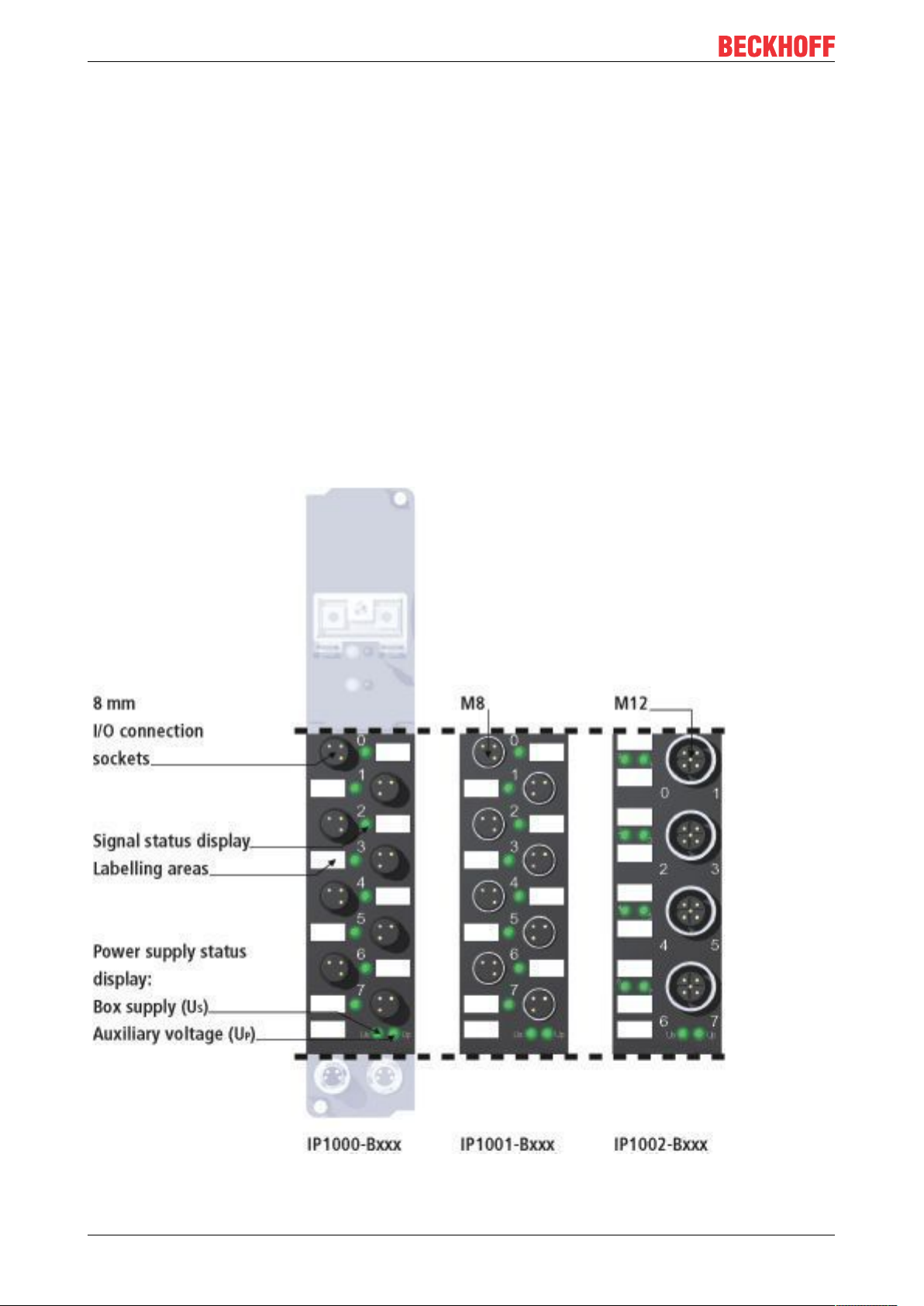
3.1.1.1 IP100x-Bxxx, IE100x
8 Channel Digital Input (Filter 3.0 ms) 24 V
The IP100x digital input modules acquire the binary control signals from the process level and transmit them
to the higher-level automation unit. The state of the signals is indicated by light emitting diodes. The signals
are optionally connected via 8mm snap-in plugs (IP1000), screw-in M8 connectors (IP1001) or screw-in M12
connectors (IP1002). The sensors are supplied from the control voltage US. The load voltage UP is not used
in the input module, but may be connected in order to be relayed downstream.
DC
Fieldbus Box I/O-Modules16 Version: 2.0.0
Page 17

I/O-Modules
Technical data IP1000-Bxxx, IE1000 IP1001-Bxxx, IE1001 IP1002-Bxxx, IE1002
Number of inputs 8
Input connections Ø 8 snap on M8 screw-in M12 screw-in
Input filter 3.0 ms
Nominal input voltage 24 VDC (20 V... 29 V)
Signal voltage '0' -3 V... 5 V (EN61131-2, type 2)
Signal voltage '1' 11 V... 30 V (EN61131-2, type 2)
Input current typical 6 mA (EN61131-2, type 2)
Sensor supply derived from the control voltage, max. 0.5 A per channel, fully short-circuit proof
Power supply Feed: 1 x M8 connector, 4-pin; downstream connection: 1 x M8 socket, 4-pin
Bits in process image 8 bits input
Electrical isolation control voltage / fieldbus: yes
channels / control voltage: no
between the channels: no
Permissible ambient
temperature during
operation
Permissible ambient
temperature during
storage
Vibration / shock
resistance
EMC resistance burst /
ESD
Protection class IP65, IP66, IP67 (conforms to EN 60529)
Installation position variable
0°C ... +55°C
-25 °C ... +85°C
conforms to EN60068-2-6/ EN60068-2-27
conforms to EN 61000-6-2 / EN 61000-6-4
See the connection diagram [}96] for the connector pin assignment.
See the mapping description [}150] for details of the mapping.
See dimension page [}68] for weight and dimensions.
Fieldbus Box I/O-Modules 17Version: 2.0.0
Page 18

I/O-Modules
3.1.1.2 IP101x-Bxxx, IE101x
8 Channel Digital Input 24 VDC, Filter 0.2 ms
The IP101x digital input modules acquire the binary control signals from the process level and transmit them
to the higher-level automation unit. The state of the signals is indicated by light emitting diodes. The signals
are optionally connected via 8mm snap-in plugs (IP1010), screw-in M8 connectors (IP1011) or screw-in M12
connectors (IP1012). The sensors are supplied from the control voltage US. The load voltage UP is not used
in the input module, but may be connected in order to be relayed downstream.
Fieldbus Box I/O-Modules18 Version: 2.0.0
Page 19

I/O-Modules
Technical data IP1010-Bxxx / IE1010 IP1011-Bxxx / IE1011 IP1012-Bxxx / IE1012
Number of inputs 8
Input connections Ø 8 snap on M8 screw-in M12 screw-in
Input filter 0.2 ms
Nominal input voltage 24 VDC (20 V... 29 V)
Signal voltage '0' -3 V... 5 V (EN61131-2, type 2)
Signal voltage '1' 11 V... 30 V (EN61131-2, type 2)
Input current typical 6 mA (EN61131-2, type 2)
Sensor supply derived from the control voltage, max. 0.5 A per channel, fully short-circuit proof
Power supply Feed: 1 x M8 connector, 4-pin; downstream connection: 1 x M8 socket, 4-pin
Bits in process image 8 bits input
Electrical isolation control voltage / fieldbus: yes
channels / control voltage: no
between the channels: no
Permissible ambient
temperature during
operation
Permissible ambient
temperature during
storage
Vibration / shock
resistance
EMC resistance burst /
ESD
Protection class IP65, IP66, IP67 (conforms to EN 60529)
Installation position variable
0°C ... +55°C
-25 °C ... +85°C
conforms to EN60068-2-6/ EN60068-2-27
conforms to EN 61000-6-2 / EN 61000-6-4
See the connection diagram [}97] for the connector pin assignment.
See the mapping description [}150] for details of the mapping.
See dimension page [}68] for weight and dimensions.
Fieldbus Box I/O-Modules 19Version: 2.0.0
Page 20

I/O-Modules
3.1.2 Digital Output Modules
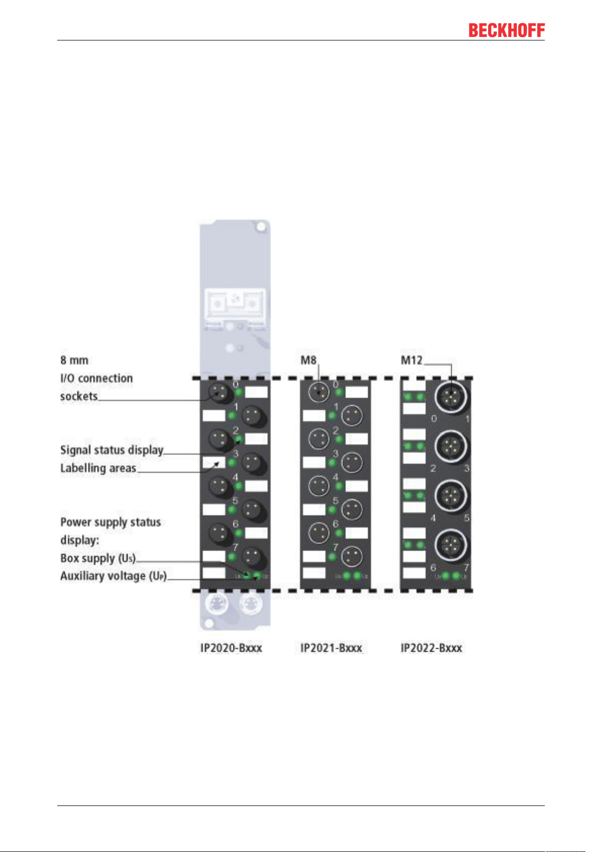
3.1.2.1 IP200x-Bxxx, IE200x
8 Channel Digital Output 24VDC, I
The IP200x digital output modules connect the binary control signals from the automation unit on to the
actuators at the process level. The 8 outputs handle load currents of up to 0.5A, and indicate their status
through light emitting diodes. The signals are optionally connected via 8mm snap-in plugs (IP2000), screwin M8 connectors (IP2001) or screw-in M12 connectors (IP2002). The outputs are short-circuit proof and
protected against inverse connection.
=0.5A
max
Fieldbus Box I/O-Modules20 Version: 2.0.0
Page 21

I/O-Modules
Technical data IP2000-Bxxx / IE2000 IP2001-Bxxx / IE2001 IP2002-Bxxx / IE2002
Number of outputs 8
Output connections Ø 8 snap on M8 screw-in M12 screw-in
Load type ohmic, inductive, lamp load
Nominal voltage 24 VDC (20 V ... 29 V)
Output current max. 0.5 A on each channel, individually short-circuit proof
Short circuit current typical 1.5 A
Load voltage current
consumption
Sensor supply derived from the control voltage, max. 0.5 A per channel, fully short-circuit proof
Power supply Feed: 1 x M8 connector, 4-pin; downstream connection: 1 x M8 socket, 4-pin
Bits in process image 8 bits output
Electrical isolation control voltage/ fieldbus: yes
Permissible ambient
temperature during
operation
Permissible ambient
temperature during
storage
Vibration / shock
resistance
EMC resistance burst /
ESD
Protection class IP65, IP66, IP67 (conforms to EN 60529)
Installation position variable
typical 20mA per channel
channels / control voltage: no
between the channels: no
0°C ... +55°C
-25 °C ... +85°C
conforms to EN60068-2-6/ EN60068-2-27
conforms to EN 61000-6-2 / EN 61000-6-4
See the connection diagram [}99] for details of the connection.
See the mapping description [}153] for details of the mapping.
See dimension page [}68] for weight and dimensions.
Fieldbus Box I/O-Modules 21Version: 2.0.0
Page 22
I/O-Modules
3.1.2.2 IP202x-Bxxx, IE202x
8 Channel Digital Output 24VDC, I
=2.0 A (total current max. 4 A)
max
The IP202x digital output modules connect the binary control signals from the automation unit on to the
actuators at the process level. The 8 outputs handle load currents of up to 2 A each, although the total
current is limited to 4A. This makes these modules particularly suitable for applications in which not all of the
outputs are active at the same time, or in which not all of the actuators draw 2A signal current. The signal
state is indicated by means of light emitting diodes.
The signals are optionally connected via 8mm snap-in plugs (IP2020), screw-in M8 connectors (IP2021) or
screw-in M12 connectors (IP2022). The outputs are short-circuit proof and protected against inverse
connection.
Fieldbus Box I/O-Modules22 Version: 2.0.0
Page 23

I/O-Modules
Technical data IP2020-Bxxx / IE2020 IP2021-Bxxx / IE2021 IP2022-Bxxx / IE2022
Number of outputs 8
Output connections Ø 8 snap on M8 screw-in M12 screw-in
Load type ohmic, inductive, lamp load
Nominal voltage 24 VDC (20 V... 29 V)
Output current max. 2.0 A each channel, individually short-circuit proof, total current max. 4 A
Short circuit current typical 4.0 A
Load voltage current
consumption
Sensor supply derived from the control voltage, max. 0.5 A per channel, fully short-circuit proof
Power supply Feed: 1 x M8 connector, 4-pin; downstream connection: 1 x M8 socket, 4-pin
Bits in process image 8 bits output
Electrical isolation control voltage / fieldbus: yes
Permissible ambient
temperature during
operation
Permissible ambient
temperature during
storage
Vibration / shock
resistance
EMC resistance burst /
ESD
Protection class IP65, IP66, IP67 (conforms to EN 60529)
Installation position variable
typical 30 mA per channel
channels / control voltage: no
between the channels: no
0°C ... +55°C
-25 °C ... +85°C
conforms to EN60068-2-6/ EN60068-2-27
conforms to EN 61000-6-2 / EN 61000-6-4
See the connection diagram [}100] for details of the connection.
See the mapping description [}153] for details of the mapping.
See dimension page [}68] for weight and dimensions.
Fieldbus Box I/O-Modules 23Version: 2.0.0
Page 24
I/O-Modules
3.1.2.3 IP204x-Bxxx, IE204x
8 Channel Digital Output 24 VDC, I
= 2.0 A (total current max. 12 A)
max
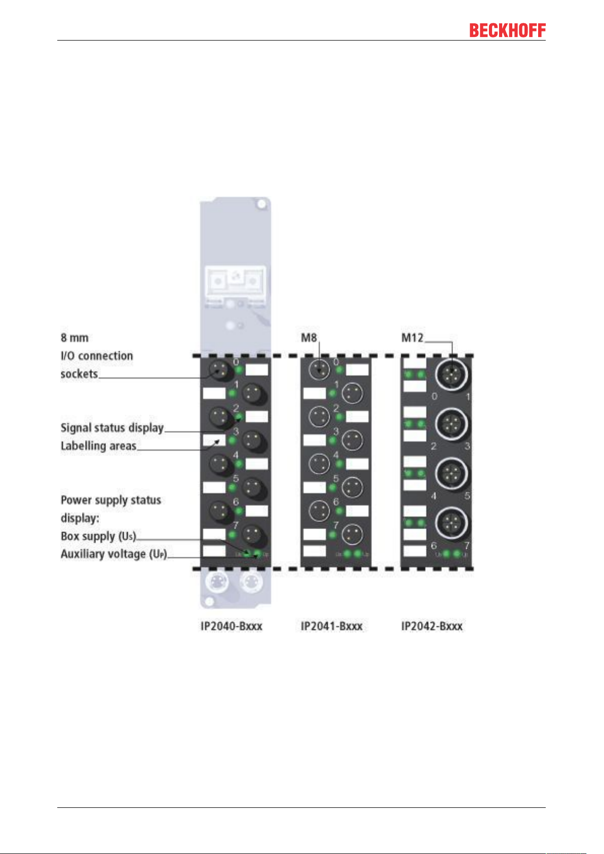
The IP204x digital output modules connect the binary control signals from the automation unit on to the
actuators at the process level. The 8 outputs handle load currents of up to 2A each, although the total
current is limited to 12 A. The outputs are supplied by three load circuits; for this reason these modules do
not relay the supply voltage. The signal state is indicated by means of light emitting diodes. The signals are
optionally connected via 8 mm snap-on plugs (IP2040), screw-in M8 connectors (IP2041) or screw-in M12
connectors (IP2042). The outputs are short-circuit proof and protected against inverse connection.
Fieldbus Box I/O-Modules24 Version: 2.0.0
Page 25

I/O-Modules
Technical data IP2040-Bxxx / IE2040 IP2041-Bxxx / IE2041 IP2042-Bxxx / IE2042
Number of outputs 8
Output connections Ø 8 snap on M8 screw-in M12 screw-in
Load type ohmic, inductive, lamp load
Nominal voltage 24 VDC (20 V ... 29 V)
Output current max. 2.0 A per channel, individually short-circuit proof, total current 12A:
- channels 0...3:S 4A
- channels 4...5:S4 A
- channels 6...7:S 4A
Short circuit current typical 4.0 A
Load voltage current
consumption
Sensor supply derived from the control voltage, max. 0.5 A per channel, fully short-circuit proof
Power supply Feed: 2 x M8 connector, 4-pin; no downstream connection
Bits in process image 8 bits output
Electrical isolation control voltage/ fieldbus: yes
Permissible ambient
temperature during
operation
Permissible ambient
temperature during
storage
Vibration / shock
resistance
EMC resistance burst /
ESD
Protection class IP65, IP66, IP67 (conforms to EN 60529)
Installation position variable
typical 50 mA per channel
channels/ control voltage: no
between the channels: no
0°C ... +55°C
-25 °C ... +85°C
conforms to EN60068-2-6/ EN60068-2-27
conforms to EN 61000-6-2 / EN 61000-6-4
See the connection diagram [}101] for details of the connection.
See the mapping description [}153] for details of the mapping.
See dimension page [}68] for weight and dimensions.
Fieldbus Box I/O-Modules 25Version: 2.0.0
Page 26
I/O-Modules
3.1.2.4 IE2808
16 Channel Digital Output 24 VDC, I
= 2,0 A (total current max. 4A)
max
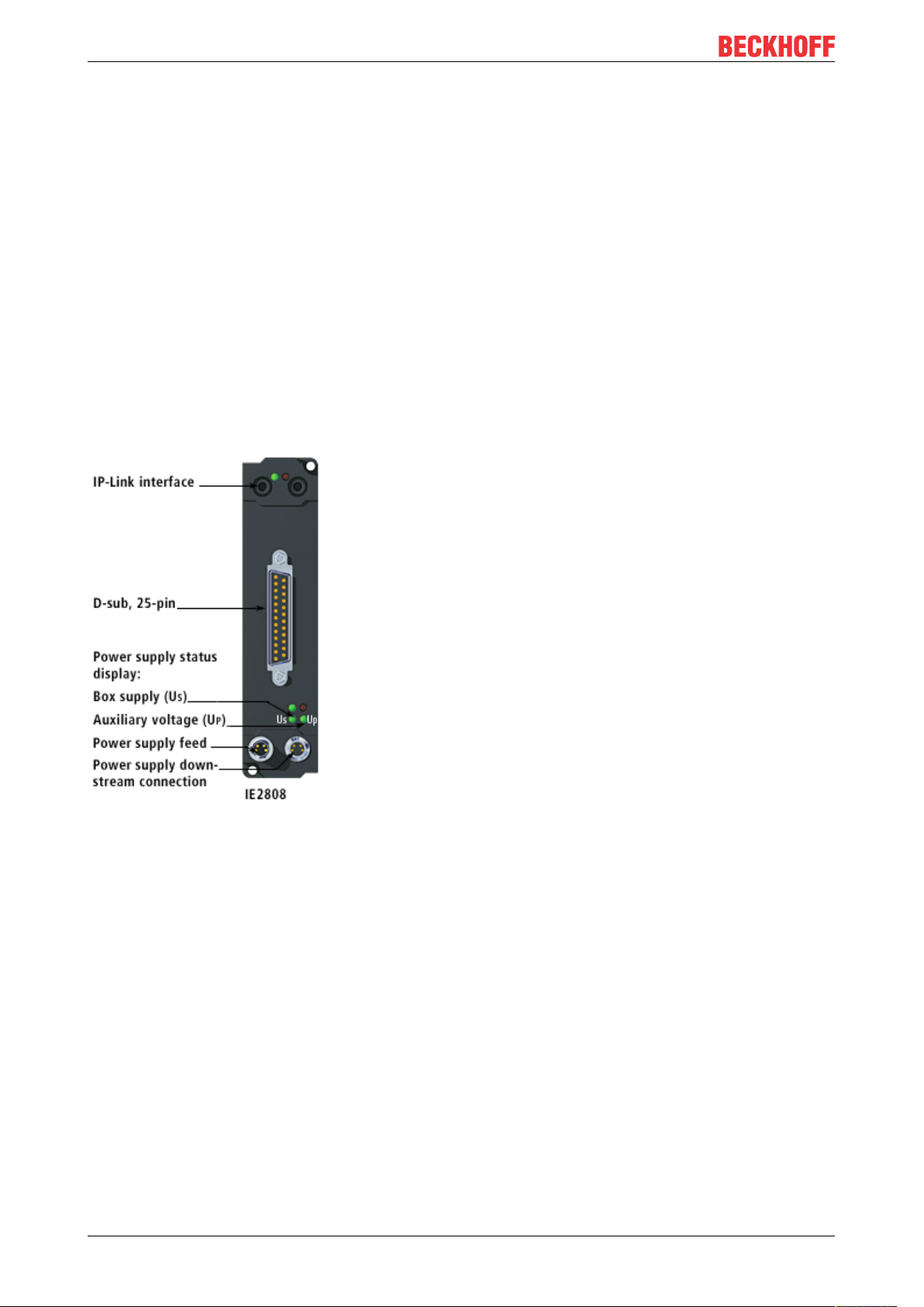
The IE2808 digital output module connects the binary control signals from the automation unit on to the
actuators at the process level. The 16 outputs handle load currents of up to 0.5 A each, although the total
current is limited to 4 A. This makes these modules particularly suitable for applications in which not all of the
outputs are active at the same time, or in which not all of the actuators draw 0.5 A current. An output shortcircuit is recognized and passed on to the controller. The signal state is indicated by means of light emitting
diodes. The signal connection is realized by the 25-pin D-sub socket. The outputs are short-circuit safe and
protected against inverse connection.
Via register R32 and R33 default values can be activated, this means these values are set when
communication is lost.
With R32 this error handling can be activated. In register R33 the value (On or OFF) is specified for every
output.
Fieldbus Box I/O-Modules26 Version: 2.0.0
Page 27

I/O-Modules
Technical data IE2808-0000 IE2808-0001
Number of outputs 8
Output connection D-sub socket, 25-pin, UNC tread
Load type resistance, inductive, lamp load
Rated load voltage 24 VDC (20V...29V)
Output current max. 0,5 A per channel, individually short-circuit safe, total current max.
4 A
Short circuit current maximal 1,5A
Load voltage current consumption typical 5mA per channel
Power supply Feed: 1 x M8 male socket, 4-pole
downstream connection: 1 x M8 female socket, 4-pole
Bits in process image 16 bit output, 16 bit input (diagnostic), optional: control/status byte
Reset of error display [}200]
Electrical isolation control voltage/ fieldbus: yes, via IP-Link
Permissible ambient temperature
during operation
Permissible ambient temperature
during storage
Vibration / shock resistance conforms to EN60068-2-6/ EN60068-2-27
EMC resistance burst / ESD conforms to EN61000-6-2/ EN61000-6-4
Protection class IP65, IP66, IP67 (conforms to EN 60529)
Installation position variable
manually automatically
channels / control voltage: no
between the channels: no
0°C ... +55°C
-25°C ... +85°C
See the connection diagramm [}110] for details of connection.
See the mapping description [}158] for details on the mapping.
See dimension page [}68] for weight and dimensions.
Fieldbus Box I/O-Modules 27Version: 2.0.0
Page 28
I/O-Modules
3.1.3 Digital Combi Modules
3.1.3.1 IP230x-Bxxx, IE230x
4 digital inputs (3.0 ms input filter) and 4 digital outputs, 24 VDC, I
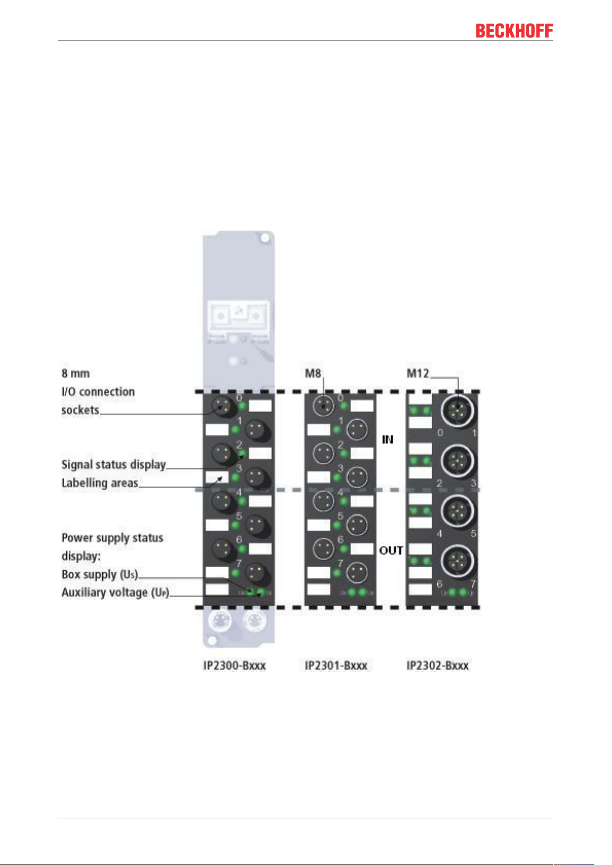
The IP230x digital I/O modules combine 4 digital inputs with a 3 ms input filter and four digital outputs in one
device. The outputs handle load currents of up to 0.5A, are short-circuit proof and protected against inverse
polarity. The state of each signal is indicated by means of light emitting diodes. The signals are connected
optionally via 8mm snap-on plugs (IP2300), screw-in M8 connectors (IP2301) or screw-in M12 connectors
(IP2302).
=0.5 A
max
Fieldbus Box I/O-Modules28 Version: 2.0.0
Page 29

I/O-Modules
Technical data IP2300-Bxxx / IE2300 IP2301-Bxxx / IE2301 IP2302-Bxxx / IE2302
Number of outputs 4 inputs and 4 outputs
Output connections Ø 8 snap on M8 screw-in M12 screw-in
Input filter 3.0 ms
Signals „0“ / „1“ -3 ... 5 V / 11 ... 30 V, 6 mA input current (EN61131-2, type 2)
Load type ohmic, inductive, lamp load
Rated load voltage 24 VDC (20 V ... 29 V)
Output current max. 0.5 A on each channel, individually short-circuit proof
Short circuit current typical 1.5 A
Load voltage current
consumption
Sensor supply derived from the control voltage, max. 0.5 A per channel, fully short-circuit proof
Power supply Feed: 1 x M8 connector, 4-pin; downstream connection: 1 x M8 socket, 4-pin
Bits in process image 4 bits input and 4 bits output
Electrical isolation control voltage/ fieldbus: yes
Permissible ambient
temperature during
operation
Permissible ambient
temperature during
storage
Vibration / shock
resistance
EMC resistance burst /
ESD
Protection class IP65, IP66, IP67 (conforms to EN 60529)
Installation position variable
typical 20 mA per channel
channels/ control voltage: no,
between the channels: no,
0°C ... +55°C
-25 °C ... +85°C
conforms to EN60068-2-6/ EN60068-2-27
conforms to EN 61000-6-2 / EN 61000-6-4
See the connection diagram [}102] for details of the connection.
See the mapping description [}154] for details of the mapping.
See dimension page [}68] for weight and dimensions.
Fieldbus Box I/O-Modules 29Version: 2.0.0
Page 30
I/O-Modules
3.1.3.2 IP231x-Bxxx, IE231x
4 digital inputs (0.2 ms input filter) and 4 digital outputs, 24 VDC, I
=0.5 A
max
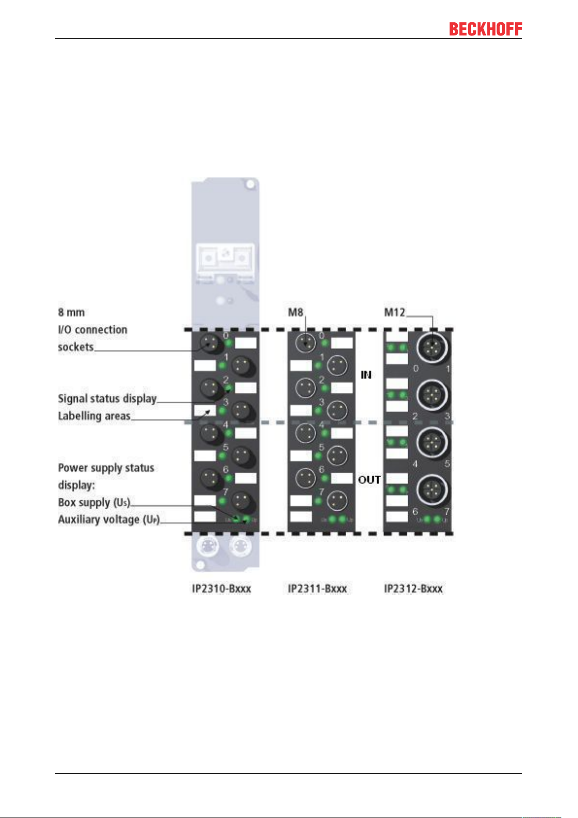
The IP231x digital I/O modules combine 4 digital inputs with a 0.2 ms input filter and four digital outputs in
one device. The outputs handle load currents of up to 0.5 A, are short-circuit proof and protected against
inverse polarity. The state of each signal is indicated by means of light emitting diodes. The signals are
connected optionally via 8 mm snap-on plugs (IP2310), screw-in M8 connectors (IP2311) or screw-in M12
connectors (IP2312).
Fieldbus Box I/O-Modules30 Version: 2.0.0
Page 31

I/O-Modules
Technical data IP2310-Bxxx / IE2310 IP2311-Bxxx / IE2311 IP2312-Bxxx / IE2312
Number of outputs 4 inputs and 4 outputs
Output connections Ø 8 snap on M8 screw-in M12 screw-in
Input filter 0.2 ms
Signals „0“ / „1“ -3... 5 V / 11 ... 30 V, 6 mA input current (EN61131-2, type 2)
Load type ohmic, inductive, lamp load
Rated load voltage 24 VDC (20 V ... 9 V)
Output current max. 0.5 A on each channel, individually short-circuit proof
Short circuit current typical 1.5 A
Load voltage current
consumption
Sensor supply derived from the control voltage, max. 0.5 A per channel, fully short-circuit proof
Power supply Feed: 1 x M8 connector, 4-pin; downstream connection: 1 x M8 socket, 4-pin
Bits in process image 4 bits input and 4 bits output
Electrical isolation control voltage / fieldbus: yes
Permissible ambient
temperature during
operation
Permissible ambient
temperature during
storage
Vibration / shock
resistance
EMC resistance burst /
ESD
Protection class IP65, IP66, IP67 (conforms to EN 60529)
Installation position variable
typical 20 mA per channel
channels / control voltage: no
between the channels: no
0°C ... +55°C
-25 °C ... +85°C
conforms to EN60068-2-6/ EN60068-2-27
conforms to EN 61000-6-2 / EN 61000-6-4
See the connection diagram for details of the connection.
See the mapping description [}154] for details of the mapping.
See dimension page [}68] for weight and dimensions.
Also see about this
2 IP231x-Bxxx, IE231x Signal Connection [}103]
Fieldbus Box I/O-Modules 31Version: 2.0.0
Page 32

I/O-Modules
3.1.3.3 IP232x-Bxxx, IE232x
4 digital inputs (3.0 ms input filter) and 4 digital outputs, 24 VDC, I
=2.0 A, total current 4 A
max
The IP232x digital I/O modules combine 4 digital inputs with a 3ms input filter and four digital outputs in one
device. The outputs handle load currents of up to 2.0A, are short-circuit proof and protected against inverse
polarity. The state of each signal is indicated by means of light emitting diodes. The signals are connected
optionally via 8mm snap-on plugs (IP2320), screw-in M8 connectors (IP2321) or screw-in M12 connectors
(IP2322).
Fieldbus Box I/O-Modules32 Version: 2.0.0
Page 33

I/O-Modules
Technical data IP2320-Bxxx / IE2320 IP2321-Bxxx / IE2321 IP2322-Bxxx / IE2322
Number of outputs 4 inputs and 4 outputs
Output connections Ø 8 snap on M8 screw-in M12 screw-in
Input filter 3.0 ms
Signals „0“ / „1“ -3 ... 5 V / 11 ... 30 V, 6 mA input current (EN61131-2, type 2)
Load type ohmic, inductive, lamp load
Rated load voltage 24 VDC (20 V ... 29 V)
Output current max. 2.0 A each channel, individually short-circuit proof, total current 4 A
Short circuit current typical 4.0 A
Load voltage current
consumption
Sensor supply derived from the control voltage, max. 0.5 A per channel, fully short-circuit proof
Power supply Feed: 1 x M8 connector, 4-pin; downstream connection: 1 x M8 socket, 4-pin
Bits in process image 4 bits input and 4 bits output
Electrical isolation control voltage/ fieldbus: yes
Permissible ambient
temperature during
operation
Permissible ambient
temperature during
storage
Vibration / shock
resistance
EMC resistance burst /
ESD
Protection class IP65, IP66, IP67 (conforms to EN 60529)
Installation position variable
typical 30 mA per channel
channels / control voltage: no
between the channels: no
0°C ... +55°C
-25 °C ... +85°C
conforms to EN60068-2-6/ EN60068-2-27
conforms to EN 61000-6-2 / EN 61000-6-4
See the connection diagram [}104] for details of the connection.
See the mapping description [}154] for details of the mapping.
See dimension page [}68] for weight and dimensions.
Fieldbus Box I/O-Modules 33Version: 2.0.0
Page 34

I/O-Modules
3.1.3.4 IP233x-Bxxx, IE233x
4 digital inputs (0.2 ms input filter) and 4 digital outputs 24 VDC, I
=2.0 A, total current 4 A
max
The IP233x digital I/O modules combine 4 digital inputs with a 0.2 ms input filter and four digital outputs in
one device. The outputs handle load currents of up to 2.0A, are short-circuit proof and protected against
inverse polarity. The state of each signal is indicated by means of light emitting diodes. The signals are
connected optionally via 8mm snap-on plugs (IP2330), screw-in M8 connectors (IP2331) or screw-in M12
connectors (IP2332).
Fieldbus Box I/O-Modules34 Version: 2.0.0
Page 35

I/O-Modules
Technical data IP2330-Bxxx / IE2330 IP2331-Bxxx / IE2331 IP2332-Bxxx / IE2332
Number of outputs 4 inputs and 4 outputs
Output connections Ø 8 snap on M8 screw-in M12 screw-in
Input filter 0.2 ms
Signals „0“ / „1“ -3... 5 V / 11 ... 30 V, 6 mA input current (EN61131-2, type 2)
Load type ohmic, inductive, lamp load
Rated load voltage 24 VDC (20 V ... 29 V)
Output current max. 2.0 A each channel, individually short-circuit proof, total current 4 A
Short circuit current typical 4.0 A per channel
Load voltage current
consumption
Sensor supply derived from the control voltage, max. 2.0 A per channel, fully short-circuit proof
Power supply Feed: 1 x M8 connector, 4-pin; downstream connection: 1 x M8 socket, 4-pin
Bits in process image 4 bits input and 4 bits output
Electrical isolation control voltage/ fieldbus: yes
Permissible ambient
temperature during
operation
Permissible ambient
temperature during
storage
Vibration / shock
resistance
EMC resistance burst /
ESD
Protection class IP65, IP66, IP67 (conforms to EN 60529)
Installation position variable
typical 30 mA
channels/ control voltage: no
between the channels: no
0°C ... +55°C
-25 °C ... +85°C
conforms to EN60068-2-6/ EN60068-2-27
conforms to EN 61000-6-2 / EN 61000-6-4
See the connection diagram for details of the connection.
See the mapping description [}154] for details of the mapping.
See dimension page [}68] for weight and dimensions.
Also see about this
2 IP233x-Bxxx, IE233x Signal Connection [}105]
Fieldbus Box I/O-Modules 35Version: 2.0.0
Page 36

I/O-Modules
3.1.3.5 IP240x-Bxxx, IE240x
8 digital inputs (3.0 ms input filter) and 8 digital outputs 24 VDC, I
=0.5 A
max
The IP240x digital I/O modules have 8 channels that can be used either as inputs or as outputs. The device
can therefore be flexibly adapted to the requirements of the application. The signals are connected optionally
through snap-on 8 mm connectors (IP2400) or through screw-in M8 connectors (IP2401), both of which have
4 pins (with separate input and output pins). This makes it possible to connect antivalent sensors. Adapter
cables are available for use in input-only or output-only cases, as well as connectors for field assembly. It is
also possible to use the power supply cable directly as the sensor cable. The outputs handle load currents of
up to 0.5A, are short-circuit proof and protected against inverse polarity. The state of each signal is
indicated by means of light emitting diodes.
Fieldbus Box I/O-Modules36 Version: 2.0.0
Page 37

I/O-Modules
Technical data IP2400-Bxxx / IE2400 IP2401-Bxxx / IE2401
Number of outputs 8 inputs and 8 outputs
Output connections Ø 8 snap on M8 screw-in
Input filter 3.0 ms
Signals „0“ / „1“ -3 ... 5 V / 11 ... 30 V, 6 mA input current (EN61131-2, type 2)
Load type ohmic, inductive, lamp load
Rated load voltage 24 VDC (20 V ... 29 V)
Output current max. 0.5 A on each channel, individually short-circuit proof
Short circuit current typical 1.5 A
Load voltage current consumption typical 20 mA per channel
Sensor supply derived from the control voltage, max. 0.5 A per channel, fully short-
circuit proof
Power supply Feed: 1 x M8 connector, 4-pin; downstream connection: 1 x M8 socket,
4-pin
Bits in process image 8 bits input and 8 bits output
Electrical isolation control voltage/ fieldbus: yes
channels/ control voltage: no
between the channels: no
Permissible ambient temperature
during operation
Permissible ambient temperature
during storage
Vibration / shock resistance conforms to EN60068-2-6/ EN60068-2-27
EMC resistance burst / ESD conforms to EN 61000-6-2 / EN 61000-6-4
Protection class IP65, IP66, IP67 (conforms to EN 60529)
Installation position variable
0°C ... +55°C
-25 °C ... +85°C
See the connection diagram for details of the connection.
See the mapping description [}155] for details of the mapping.
See dimension page [}68] for weight and dimensions.
Also see about this
2 IP240x-Bxxx, IE240x Signal Connection [}106]
Fieldbus Box I/O-Modules 37Version: 2.0.0
Page 38

I/O-Modules
3.1.3.6 IE2403
8 digital inputs (3.0 ms input filter) and 8 digital outputs 24 VDC, Imax=0.5 A
The digital IE2403 combi module has 16 channels with 8 inputs and 8 outputs. The device can therefore be
flexibly adapted to the requirements of the application. The outputs handle load currents of up to 0.5 A. They
are short-circuit-proof and protected against inverse polarity. KM-connectors with a spring-loaded system are
used for the signal connection. These connectors are optionally available with 1 or 3 pins. The module is
supplied without KM-connectors.
NOTE
Attention
The IE2403 combi module conforms to protection class IP20. It is intended to be used within switch boards,
control panels or switch cabinets to integrate their signals into IP link.The IE2403 combi module conforms
not to protection classes IP65/IP67!
Fieldbus Box I/O-Modules38 Version: 2.0.0
Page 39

I/O-Modules
Technical data IE2403
Number of channels 16 (8 inputs and 8 outputs)
Input connections Via KM connector ZS2001 (not included in delivery of
IE2403).
Please order the desired type for single- or tree-wire
technique (see ordering information [}125] and
technical data [}126]).
Input filter 3.0ms
Signals „0“ / „1“ -3 ... 5 V / 11 ... 30 V, 6mA input current
(EN61131-2, type 2)
Sensor supply derived from the control voltage, max. 0.5 A per
channel, fully short-circuit proof
Output connections Via KM connector ZS2001 (not included in delivery of
IE2403).
Please order the desired type for single- or tree-wire
technique (see ordering information [}125] and
technical data [}126]).
Rated load voltage 24 VDC (20 V ... 29 V)
Load type ohmic, inductive, lamp load
Output current max. 0.5 A on each channel, individually short-circuit
proof
Short circuit current typical 1.5 A
Load voltage current consumption typical 20mA per channel
Power supply Feed: 1 x M8 connector, 4-pin
downstream connection: 1 x M8 socket, 4-pin
Bits in process image 8 bits input and 8 bits output
Electrical isolation control voltage/ fieldbus: yes, via IP-Link
channels/ control voltage: no
between the channels: no
Permissible ambient temperature during operation 0°C ... +55°C
Permissible ambient temperature during storage -25°C ... +85°C
Vibration / shock resistance conforms to EN60068-2-6/ EN60068-2-27
EMC resistance burst / ESD conforms to EN61000-6-2/ EN61000-6-4
Protection class IP20
Mounting position any
See the connection description [}107] for details of the connection.
See themapping description [}155] for details of the mapping.
See dimension page [}68] for weight and dimensions.
Fieldbus Box I/O-Modules 39Version: 2.0.0
Page 40

I/O-Modules
3.1.4 Analog Input Modules
3.1.4.1 IP3102-Bxxx, IE3102
4 Channel Analog Input ± 10 V
The IP3102 analog input module handles signals in the range from -10 V to +10 V. The voltage is digitized to
a resolution of 16 bits, and is transmitted, electrically isolated, to the higher-level automation device. The
input channels have differential inputs and possess a common, internal ground potential. The applied load
voltage (which can be any value up to 30 VDC) is fed through to supply the sensor. It is thus possible, for
instance, to supply a measuring potentiometer with 10 VDC from an external voltage source. The module is
quite versatile, but default settings have been selected in such a way that in most cases it is not necessary to
perform configuration. The input filter and associated conversion times can be set within a wide range, and
several data output formats may be chosen. The inputs can, if required, be scaled differently, and automatic
limit monitoring is also available. Parameterization may be carried out either via the fieldbus or using the
KS2000 software tool.
Fieldbus Box I/O-Modules40 Version: 2.0.0
Page 41

I/O-Modules
Technical data IP3102-Bxxx / IE3102
Number of channels 4 analog inputs
Output connections M12 screw-in
Nominal input range -10 V ... +10 V
Input resistance > 100 kΩ
Common mode voltage 35 V max.
Conversion time 250 ms (default), configurable to 5 ms
Resolution 15 bits + arithmetic sign
Relative measurement error < ± 0,3% of the full scale value
Input filter 10 variations inc. averaging, configurable
Sensor supply from load supply voltage UP, DC, any value up to 30
V
Power supply Feed: 1 x M8 connector, 4-pin; downstream
connection: 1 x M8 socket, 4-pin
Bits in process image I: 4 x 16 bits, optional I/O: 4 x 8 bits control/state + 4
x 16 bits
Electrical isolation control voltage/ fieldbus: yes
channels/ control voltage: 500 V
between the channels: no
Permissible ambient temperature during operation 0°C ... +55°C
Permissible ambient temperature during storage -25 °C ... +85°C
Vibration / shock resistance conforms to EN60068-2-6/ EN60068-2-27
EMC resistance burst / ESD conforms to EN 61000-6-2 / EN 61000-6-4
Protection class IP65, IP66, IP67 (conforms to EN 60529)
Installation position variable
See the Connection diagram [}111] for details of the connection.
See the Parameterization description [}206] for details of the parameterization.
See the Mapping description [}159] for details of the mapping.
See dimension page [}68] for weight and dimensions.
Fieldbus Box I/O-Modules 41Version: 2.0.0
Page 42

I/O-Modules
3.1.4.2 IP3112-Bxxx, IE3112
4 Channel Analog Input, from 0 to 20 mA
The IP3112 analog input module handles signals in the range from 0 to 20 mA. The input current is digitized
to a resolution of 16 bits (the default is 15 bits), and is transmitted, electrically isolated, to the higher-level
automation device. The input channels have differential inputs and possess a common, internal ground
potential. The applied load voltage (which can be any value up to 30 VDC) is fed through to supply the sensor.
The module is quite versatile, but default settings have been selected in such a way that in most cases it is
not necessary to perform configuration. The input filter and associated conversion times can be set within a
wide range, and several data output formats may be chosen. The inputs can, if required, be scaled
differently, and automatic limit monitoring is also available. Parameterization may be carried out either via
the fieldbus or, using the KS2000 software tool, through the configuration interface. The parameters are
stored in the module.
Fieldbus Box I/O-Modules42 Version: 2.0.0
Page 43

I/O-Modules
Technical data IP3112-Bxxx / IE3112
Number of channels 4 analog inputs
Output connections M12 screw-in
Nominal input range 0 ... 20 mA
Input resistance 80 Ω measuring resistance
Common mode voltage max. 35 V
Conversion time 140 ms
Resolution 15 bits + arithmetic sign
Relative measurement error < ± 0,3% of the full scale value
Input filter 10 variations inc. averaging, configurable
Sensor supply from load supply voltage Up, DC, any value up to 30
V
Power supply Feed: 1 x M8 connector, 4-pin; downstream
connection: 1 x M8 socket, 4-pin
Bits in process image I: 4 x 16 bits, optional I/O: 4 x 8 bits control/state + 4
x 16 bits
Electrical isolation control voltage/ fieldbus: yes
channels/ control voltage: 500V
between the channels: no
Permissible ambient temperature during operation 0°C ... +55°C
Permissible ambient temperature during storage -25 °C ... +85°C
Vibration / shock resistance conforms to EN60068-2-6/ EN60068-2-27
EMC resistance burst / ESD conforms to EN 61000-6-2 / EN 61000-6-4
Protection class IP65, IP66, IP67 (conforms to EN 60529)
Installation position variable
See the connection diagram [}112] for details of the connection.
See the parameterization description [}213] for details of the parameterization.
See the mapping description [}161] for details of the mapping.
See dimension page [}68] for weight and dimensions.
Fieldbus Box I/O-Modules 43Version: 2.0.0
Page 44

I/O-Modules
3.1.4.3 IP3202-Bxxx, IE3202
4 Channel Analog Input PT100 (RTD)
The IP3202 analog input module allows resistance sensors to be connected directly. The module's circuitry
can operate the sensors using 2-wire or 4-wire connection techniques. Linearization over the full temperature
range is realized with the aid of a microprocessor. The temperature range can be selected freely. The
module can also be used for resistance measurement, with the output in ohms. The module's standard
settings are: Resolution 0.1 °C in the temperature range of PT100 sensors in 4-wire connection. Sensor
malfunctions such as broken wires are indicated by error LEDs. The module is quite versatile, but default
settings have been selected in such a way that in most cases it is not necessary to perform configuration.
The input filter and associated conversion times can be set within a wide range, and several data output
formats may be chosen. The inputs can, if required, be scaled differently, and automatic limit monitoring is
also available. Parameterization may be carried out either via the fieldbus or using the KS2000 software tool.
Fieldbus Box I/O-Modules44 Version: 2.0.0
Page 45

I/O-Modules
Technical data IP3202-Bxxx / IE3202
Number of channels 4 analog inputs
Output connections M12 screw-in
Nominal input range PT100, PT200, PT500, PT1000, Ni100, Ni120,
Ni1000, resistance measurement (e.g. potentiometer)
Resolution 0.1°C per digit
Measuring current typical 0.5 A
Conversion time 260 ms
Measurement error < +/-1°C
Input filter 4 versions
Sensor supply From the load voltage, U
S
Power supply Feed: 1 x M8 connector, 4-pin; downstream
connection: 1 x M8 socket, 4-pin
Bits in process image I: 4 x 16 bits, optional I/O: 4 x 8 bits control/state + 4
x 16 bits
Electrical isolation control voltage/ fieldbus: yes
channels/ control voltage: 500V
between the channels: no
Permissible ambient temperature during operation 0°C ... +55°C
Permissible ambient temperature during storage -25 °C ... +85°C
Vibration / shock resistance conforms to EN60068-2-6/ EN60068-2-27
EMC resistance burst / ESD conforms to EN 61000-6-2 / EN 61000-6-4
Protection class IP65, IP66, IP67 (conforms to EN 60529)
Installation position variable
See the connection diagram [}113] for details of the connection.
See the parameterization description [}219] for details of the parameterization.
See the mapping description for details of the mapping.
See dimension page [}68] for weight and dimensions.
Fieldbus Box I/O-Modules 45Version: 2.0.0
Page 46

I/O-Modules
3.1.4.4 IP3312-Bxxx, IE3312
4 Channel Analog Input Thermocouple
The IP3312 analog input module permits four thermocouples to be directly connected. The module's circuit
can operate thermocouple sensors using the 2-wire technique. Linearization over the full temperature range
is realized with the aid of a microprocessor. The temperature range can be selected freely. The module can
also be used for voltage measurements in the mV range. The module's standard settings are: Resolution 0.1
°C over the temperature range of type K sensors. Sensor malfunctions such as broken wires are indicated by
error LEDs. Compensation for the cold junction is made through a temperature measurement in the
connecting plug. This means that standard extension leads can be connected.
The module is quite versatile, but default settings have been selected in such a way that in most cases it is
not necessary to perform configuration. The input filter and associated conversion times can be set within a
wide range, and several data output formats may be chosen. The inputs can, if required, be scaled
differently, and automatic limit monitoring is also available. Parameterization may be carried out either via
the fieldbus or using the KS2000 software tool.
Fieldbus Box I/O-Modules46 Version: 2.0.0
Page 47

I/O-Modules
Technical data IP3312-Bxxx / IE3312
Number of channels 4 analog inputs
Output connections M12 screw-in
Nominal input range Types J, K, L, B, E, N, R, S, T, U (default setting type
K), mV measurement
Resolution 0.1°C per digit
Conversion time 260 ms
Measurement error < +/- 0.5 % (of the full scale value)
Input filter 4 versions
Cold junction compensation via ZS2000-3712
Sensor supply From the load voltage, U
S
Power supply Feed: 1 x M8 connector, 4-pin; downstream
connection: 1 x M8 socket, 4-pin
Bits in process image I: 4 x 16 bits, optional I/O: 4 x 8 bits control/state + 4
x 16 bits
Electrical isolation control voltage/ fieldbus: yes
channels/ control voltage: 500 V
between the channels: no
Permissible ambient temperature during operation 0°C ... +55°C
Permissible ambient temperature during storage -25 °C ... +85°C
Vibration / shock resistance conforms to EN60068-2-6/ EN60068-2-27
EMC resistance burst / ESD conforms to EN 61000-6-2 / EN 61000-6-4
Protection class IP65, IP66, IP67 (conforms to EN 60529)
Installation position variable
See the connection diagram [}115] for details of the connection.
See the parameterization description [}228] for details of the parameterization.
See the mapping description for details of the mapping.
See dimension page [}68] for weight and dimensions.
Fieldbus Box I/O-Modules 47Version: 2.0.0
Page 48

I/O-Modules
3.1.5 Analog Output Modules
3.1.5.1 IP4112-Bxxx, IE4112
4 Channel Analog Output, from 0 to 20 mA
The IP/IE4112 analog output module generates analog output signals in the range from 0 to 20mA. The
power is supplied to the process level with a resolution of 15bits (default), and is electrically isolated. If the
input is transmitted without an arithmetical sign, 16 bit resolution may also be selected. If necessary, the
output scaling can be altered.
Ground potential for the four output channels is common with the 24VDC supply. The output drivers are
powered by the control voltage. The applied load voltage (which can be any value up to 30VDC) is fed
through to supply the actuators.
Fieldbus Box I/O-Modules48 Version: 2.0.0
Page 49

I/O-Modules
Technical data IP4112-Bxxx, IE4112
Number of channels 4
Output connections M12 screw-in
Output range 0 ... 20 mA
Load impedance < 500 Ω
Resolution 15 bit, configurable to 16 bit
Conversion time < 4 ms
Accuracy < ± 0.1% of the full scale value
Actuator power supply from the load voltage, U
P
Power supply Feed: 1 x M8 connector, 4-pin; downstream
connection: 1 x M8 socket, 4-pin
Bits in process image O: 4 x 16 bits data, optional: 4 x 8 bits control/status
Electrical isolation control voltage/ fieldbus: depends on the bus system
channels/ control voltage: yes
between the channels: no
Permissible ambient temperature during operation 0 °C ... 55 °C
Permissible ambient temperature during storage -25 °C ... + 85 °C
Vibration / shock resistance conforms to EN60068-2-6/ EN60068-2-27
EMC resistance burst / ESD conforms to EN 61000-6-2 / EN 61000-6-4
Protection class IP65, IP66, IP67 (conforms to EN 60529)
Installation position variable
See connections [}116] for connection details.
See the parameterization description [}236] for details of the parameterization.
See the mapping description [}167] for details of the mapping.
See dimension page [}68] for weight and dimensions.
Fieldbus Box I/O-Modules 49Version: 2.0.0
Page 50

I/O-Modules
3.1.5.2 IP4132-Bxxx, IE4132
4 Channel Analog Output, from -10V to +10V
The IP/IE4132 analog output module generates analog output signals in the range from -10V to + 10V. The
voltage is supplied to the process level with a resolution of 16bits, and is electrically isolated. If necessary,
the output scaling can be altered.
Ground potential for the four output channels is common with the 24VDC supply. The output drivers are
powered by the control voltage. The applied load voltage (which can be any value up to 30VDC) is available
for supply of the actuators.
Fieldbus Box I/O-Modules50 Version: 2.0.0
Page 51

I/O-Modules
Technical data IP4132-Bxxx
Number of channels 4
Output connections M12 screw-in
Output range -10 V/ 0 ... 10 V
Load impedance > 5 kΩ
Resolution 16 bit
Conversion time < 4 ms
Accuracy < ± 0.1% of the full scale value
Actuator power supply from the load voltage, U
P
Power supply Feed: 1 x M8 connector, 4-pin; downstream
connection: 1 x M8 socket, 4-pin
Bits in process image O: 4 x 16 bits data, optional: 4 x 8 bits control/status
Electrical isolation control voltage/ fieldbus: depends on the bus system
channels/ control voltage: yes
between the channels: no
Permissible ambient temperature during operation 0 °C ... 55 °C
Permissible ambient temperature during storage -25 °C ... + 85 °C
Vibration / shock resistance conforms to EN60068-2-6/ EN60068-2-27
EMC resistance burst / ESD conforms to EN 61000-6-2 / EN 61000-6-4
Protection class IIP65, IP66, IP67 (conforms to EN 60529)
Installation position variable
See the connection diagram [}117] for details of the connection.
See the parameterization description [}241] for details of the parameterization.
See the mapping description [}244] for details of the mapping.
See dimension page [}68] for weight and dimensions.
Fieldbus Box I/O-Modules 51Version: 2.0.0
Page 52

I/O-Modules
3.1.6 Modules for Special Functions
3.1.6.1 IP1502-Bxxx, IE1502
Counter module
The counter module has two fast counters running at up to 100 kHz. It counts binary pulses, and transmits
the counter state to the higher-level automation unit. The Up/Down input allows the counters to be switched
between upwards and downwards counting (in 32 bits). The gate signals (gate inputs) allow the counters to
be triggered: depending on the level at the gate input, the counting function is halted or enabled. The outputs
can be switched or pulsed depending on the counter state, and can therefore be used as fast control signals
for field devices. From the controller it is possible to set the counter state, to start or halt the counter
functions, and to set the outputs. The module shows the states of the input and output signals by means of
light emitting diodes.
Fieldbus Box I/O-Modules52 Version: 2.0.0
Page 53

I/O-Modules
Technical data IP1502-Bxxx / IE1502
Number of counters 2, each with a depth of 32 bits
Switching frequency 100 kHz (2 kHz when switching between up and
down)
Signal connection M12 screw-in
Number of inputs 2 counter inputs, 2 gate inputs, 2 up/down
changeovers
Nominal input voltage 24 VDC (20V...29V)
Signal voltage "0" -3V...5V (EN61131-2, type 2)
Signal voltage "1" 11V...30V (EN61131-2, type 2)
Number of outputs one output per counter, max. 0.5A, short circuit proof
Sensor supply derived from control voltage, max. 0.5A over all,
short-circuit proof
Power supply Feed: 1 x M8 connector, 4-pin; downstream
connection: 1 x M8 socket, 4-pin
Bits in process image 64 bits output (2 x 32) and 64 bits input (2 x 32) for
process data,
8bits output for Control Byte and 8bits input for
Status Byte
Electrical isolation control voltage/ fieldbus: yes
channels/ control voltage: no
between the channels: no
Permissible ambient temperature during operation 0°C ... +55°C
Permissible ambient temperature during storage -25 °C ... +85°C
Vibration / shock resistance conforms to EN60068-2-6/ EN60068-2-27
EMC resistance burst / ESD conforms to EN 61000-6-2 / EN 61000-6-4
Protection class IP65, IP66, IP67 (conforms to EN 60529)
Installation position variable
See the connection diagram [}98] for the connector pin assignment.
See the Parameterization description [}183] for details of the parameterization.
See the Mapping description [}151] for details of the mapping.
See dimension page [}68] for weight and dimensions.
Fieldbus Box I/O-Modules 53Version: 2.0.0
Page 54

I/O-Modules
3.1.6.2 IP2512-Bxxx, IE2512
2-channel pulse width output 24 V
DC
The outputs of the IP25x2 modules provide a pulse width modulated version of a binary signal. The mark/
space ratio is prescribed by a 16 bit value from the automation unit. The output stage is protected against
overload and short-circuit, the maximum output current is 2.5 A per channel. In addition to the pulse width
modulation operating mode, the outputs can also be frequency modulated, or can be used to control stepper
motors with specified pulses and direction. The modules contain two channels that indicate their signal state
by means of light emitting diodes. The LEDs are driven in time with the outputs, and show the mark/space
ratio by their brightness.
Fieldbus Box I/O-Modules54 Version: 2.0.0
Page 55

I/O-Modules
Technical data IP2512-Bxxx / IE2512
Number of outputs 2
Signal connection M12 screw type
Load type resistive, inductive
Rated load voltage 24 VDC (-15%/+20%)
Output current max. 2.5 A on each channel, individually short-circuit
safe
Base frequency 2 Hz ... 80 kHz, Default: 250 Hz
Keying ratio 0 % ... 100 % (Ton > 750 ns, T
> 500 ns)
off
Resolution max. 10 bit
Freewheeling diode (output) yes
Power supply connection Feed: 1 x M8 male socket, 4-pin; downstream
connection: 1 x M8 female socket, 4-pin
Bits width in process image 2 x 16 output bits for process data,
2 x 8 output bits for control bytes and 2 x 8 input bits
for status bytes
Electrical isolation control voltage/ fieldbus: yes
channels/ control voltage: no
between the channels: no
Permissible ambient temperature during operation 0°C ... +55°C
Permissible ambient temperature during storage -25 °C ... +85°C
Vibration / shock resistance conforms to EN60068-2-6/ EN60068-2-27
EMC resistance burst / ESD conforms to EN 61000-6-2 / EN 61000-6-4
Protection class IP65, IP66, IP67 (conforms to EN 60529)
Installation position variable
See the connection diagram [}109] for the connector pin assignment.
See the parameterization description [}191] for details of the parameterization.
See the mapping description [}156] for details of the mapping.
See dimension page [}68] for weight and dimensions.
Fieldbus Box I/O-Modules 55Version: 2.0.0
Page 56

I/O-Modules
3.1.6.3 IP5009-Bxxx, IE5009
1 channel SSI sensor interface
The IP5009 SSI interface module allows an SSI sensor to be connected directly. The sensor is powered via
the SSI interface. The interface circuit generates a pulse for reading the sensor, and makes the incoming
data stream available to the controller as a data word in the process image. The module can optionally
provide the data as binary numbers or as a Gray code. Adaptation for the direction of rotation can be
configured. Various operating modes, transmission frequencies and bit widths can be permanently stored in
a control register.
Fieldbus Box I/O-Modules56 Version: 2.0.0
Page 57

I/O-Modules
Technical data IP5009-Bxxx / IE5009
Number of channels 1
Encoder connection M23 screw-in, 12-pin
Signal type Differential signal (RS485)
Sensor supply 24VDC, from load voltage
Data transfer rate adjustable up to 1 MHz, 250kHz preset
Serial input 24 bits (adjustable)
Data direction read
Power supply Feed: 1 x M8 connector, 4-pin; downstream
connection: 1 x M8 socket, 4-pin
Bits in process image 32 input bits for process data,
Optional: 8 output bits for control byte and 8 input bits
for status byte
Electrical isolation depends on the bus system
Permissible ambient temperature during operation 0°C ... +55°C
Permissible ambient temperature during storage -25 °C ... +85°C
Vibration / shock resistance conforms to EN60068-2-6/ EN60068-2-27
EMC resistance burst / ESD conforms to EN 61000-6-2 / EN 61000-6-4
Protection class IP65, IP66, IP67 (conforms to EN 60529)
Installation position variable
See the connection diagram [}118] for the connector pin assignment.
See the parameterization description [}246] for details of the parameterization.
See the mapping description [}171] for details of the mapping.
See the derating description [}194] for details of the output current vs. frequency.
See dimension page [}68] for weight and dimensions.
Fieldbus Box I/O-Modules 57Version: 2.0.0
Page 58

I/O-Modules
3.1.6.4 IP5109-Bxxx, IE5109
1 channel Incremental Encoder Interface 1 MHz
The IP5109 module is an interface for the direct connection of incremental encoders with differential inputs
(RS485/5V) or with single inputs. A 16 bit counter with a quadrature decoder and a 16 bit latch for the zero
pulse can be read, set or enabled. The inputs can optionally be used as complementary or as single inputs.
The encoder's fault signal output, if there is one, can be connected to the status input of the interface.
Interval measurement with a resolution of 200 ns is possible. The gate input allows the counter to be locked
(high = stop).
A rising edge at the latch input from the encoder or an external sensor will store the current counter value.
Fieldbus Box I/O-Modules58 Version: 2.0.0
Page 59

I/O-Modules
Technical data IP5109-Bxxx / IE5109
Number of channels 1
Encoder connection M23 screw-in, 12-pin
Gate/latch connection M12 screw-in
Sensor supply derived from control voltage, max. 0.5 A total, short-
circuit safe
Counter 16 bit binary
Sensor supply 5 V
DC
Limit frequency 1 MHz (with 4-fold evaluation)
Quadrature decoder 1, 2, or 4-fold evaluation
Zero pulse latch 16 bit
Commands Read, set, enable
Power supply Feed: 1 x M8 connector, 4-pin; downstream
connection: 1 x M8 socket, 4-pin
Bits in process image I/O: 2 x 16 bit data, 1 x 8 bit control/status
Electrical isolation depends on the bus system
Permissible ambient temperature during operation 0°C ... +55°C
Permissible ambient temperature during storage -25 °C ... +85°C
Resistance to vibration conforms to EN60068-2-6/ EN60068-2-27
EMC resistance burst / ESD conforms to EN 61000-6-2 / EN 61000-6-4
Protection class IP65, IP66, IP67 (conforms to EN 60529)
Installation position variable
See the connection diagram [}119] for the connector pin assignment.
See the parameterization description [}251] for details of the parameterization.
See the mapping description [}173] for details of the mapping.
See dimension page [}68] for weight and dimensions.
Fieldbus Box I/O-Modules 59Version: 2.0.0
Page 60

I/O-Modules
3.1.6.5 IP5209-Bxxx
1 channel SinCos encoder interface
The IP5209 Sinus/Cosinus module functions as a interface to the higher level fieldbus for direct connection
of an measuring sensor, such as a sensing switch or encoder with 1Vss sinusoidal voltage output. The
measuring signal is processed, interpolated and made available as a 32 bit value. The signal period
resolution is 10 bit, i.e. 1024 steps. The interpolation rate can be changed via the register R35. The change
of counting direction is set via R32. The reference mark (Latch) is also stored in a 32 bit value. The current
value of the counter and the value of the reference mark can be read and can be set. The maximum
frequency for the signal input is 100 kHz.
The input frequency and therefore the velocity of the sensor, can be checked against a preset limit. If this
limit is exceeded, an error bit in the Status byte will be set!
Fieldbus Box I/O-Modules60 Version: 2.0.0
Page 61

I/O-Modules
Technical data IP5209-Bxxx
Number of counters 1
Encoder connection M23 screw-in, 12-pin
Sensor supply 5 VDC from the control voltage, max. 0.5A
Limit frequency 100 kHz (scanning of the input signals with 500 kHz)
Resolution 10 bit, 1024 steps per period
Commands Clear/set counter value, reference mark – latch,
counting direction, scaling
Power supply Feed: 1 x M8 connector, 4-pin; downstream
connection: 1 x M8 socket, 4-pin
Bits in process image I/O: 2(1) x 32 bit data (1 x 8 bit control/status)
Electrical isolation depends on the bus system
Permissible ambient temperature during operation 0°C ... +55°C
Permissible ambient temperature during storage -25 °C ... +85°C
Vibration / shock resistance conforms to EN60068-2-6/ EN60068-2-27
EMC resistance burst / ESD conforms to EN 61000-6-2 / EN 61000-6-4
Protection class IP65, IP66, IP67 (conforms to EN 60529)
Installation position variable
See the connection diagram [}120] for the connector pin assignment.
See the parameterization description [}257] for details of the parameterization.
See the mapping description [}175] for details of the mapping.
See dimension page [}68] for weight and dimensions.
Fieldbus Box I/O-Modules 61Version: 2.0.0
Page 62

I/O-Modules
3.1.7 Gateway Modules
3.1.7.1 IP6002-Bxxx, IE6002
1 channel RS 232 gateway
The IP/IE6002 serial interface module allows the connection of devices with a RS232 interface. The interface
operates in conformity with the CCITT V.28/DIN 66 259-1 standards. The module transmits the data in a fully
transparent manner to the higher-level automation device. The data is transferred via the fieldbus using a
simple handshake protocol. This does not have any effect on the protocol of the serial interface. The active
serial communication channel functions independently of the higher-level bus system in full duplex mode at
up to 19200 baud, while a 128 byte receive buffer and a 16 byte send buffer are available. The RS232
interface guarantees high immunity to interference through electrically isolated signals.
Fieldbus Box I/O-Modules62 Version: 2.0.0
Page 63

I/O-Modules
Technical data IP6002-Bxxx, IE6002
Number of channels 1 TxD and RxD, full duplex
Data transfer rate 1200 ... 19200 baud, 9600 baud (8 data bits, no
parity, one stop bit)
RS 232 connection 5 pin M12 socket, screw connection
Bit distortion < 3 %
RS 232 cable length max. 15 m
Signal voltage LOW 3 V ... 18 V
Signal voltage HIGH -18 V ... -3 V
Data buffer 128 byte receive buffer and 16 byte send buffer
Bytes in the process image I/O: 5 bytes user data, 1 byte control/status
Electrical isolation control voltage/ fieldbus: depends on the bus system
RS232 / control voltage: 500 V
Permissible ambient temperature during operation 0 °C ... 55 °C
Permissible ambient temperature during storage -25 °C ... + 85 °C
Vibration / shock resistance conforms to EN60068-2-6/ EN60068-2-27
EMC resistance burst / ESD conforms to EN 61000-6-2 / EN 61000-6-4
Protection class IP65, IP66, IP67 (conforms to EN 60529)
Installation position variable
See the connection diagram [}121] for details of the connection.
See the parameterization description [}264] for details of the parameterization.
See the mapping description [}177] for details of the mapping.
See dimension page [}68] for weight and dimensions.
Fieldbus Box I/O-Modules 63Version: 2.0.0
Page 64

I/O-Modules
3.1.7.2 IP6012-Bxxx, IE6012
1 channel TTY gateway
The IP/IE6012 module allows the connection of devices with a 20 mA current interface. The interface
operates passively. The module transmits the data in a fully transparent manner to the higher-level
automation device. The data is transferred via the fieldbus using a simple handshake protocol. This does not
have any effect on the protocol of the serial interface. The active serial communication channel functions
independently of the higher-level bus system in full duplex mode at up to 19200 baud, while a 128 byte
receive buffer and a 16 byte send buffer are available.
The current interface guarantees high immunity to interference through electrically isolated signals with
injected current.
Fieldbus Box I/O-Modules64 Version: 2.0.0
Page 65

I/O-Modules
Technical data IP6012-Bxxx, IE6012
Number of channels 1
Data transfer rate 1200 ... 19200 baud, 9600 baud (8 data bits, no
parity, one stop bit)
TTY connection 5 pin M12 socket, screw connection
Bit distortion < 3 %
TTY cable length max. 1000 m twisted pair
Signal voltage LOW 0 ... 3 mA
Signal voltage HIGH 14 ... 20 mA
Data buffer 128 byte receive buffer and 16 byte send buffer
Bytes in the process image I/O: 5 bytes user data, 1 byte control/status
Electrical isolation control voltage / fieldbus: depends on the bus system
TTY interface/ control voltage: 500 V
Permissible ambient temperature during operation 0 °C ... 55 °C
Permissible ambient temperature during storage -25 °C ... + 85 °C
Vibration / shock resistance conforms to EN60068-2-6/ EN60068-2-27
EMC resistance burst / ESD conforms to EN 61000-6-2 / EN 61000-6-4
Protection class IP65, IP66, IP67 (conforms to EN 60529)
Installation position variable
See the connection diagram [}122] for details of the connection.
See the parameterization description [}264] for details of the parameterization.
See the mapping description [}177] for details of the mapping.
See dimension page [}68] for weight and dimensions.
Fieldbus Box I/O-Modules 65Version: 2.0.0
Page 66

I/O-Modules
3.1.7.3 IP6022-Bxxx, IE6022
1 channel RS422/RS485 gateway
The IP/IE6022 module allows devices with an RS422 or RS485 interface to be connected. The module
transmits the data in a fully transparent manner to the higher-level automation device. The data is transferred
via the fieldbus using a simple handshake protocol. This does not have any effect on the protocol of the
serial interface. The active serial communication channel functions independently of the higher-level bus
system in full duplex mode at up to 19200 baud, while a 128 byte receive buffer and a 16 byte send buffer
are available. The transmission of differential signals according to RS232 guarantees high immunity to
interference through electrically isolated signals.
Fieldbus Box I/O-Modules66 Version: 2.0.0
Page 67

I/O-Modules
Technical data IP6022-Bxxx, IE6022
Number of channels 1 RS 422 full duplex, RS 485 half duplex
Data transfer rate 1200 ... 19200 baud, 9600 baud (8 data bits, no
parity, one stop bit)
RS 422/485 connection 5 pin M12 socket, screw connection
Bit transmission using differential signal
Cable impedance 120 Ω
RS 422/485 cable length max. 500 m twisted pair
Data buffer 128 byte receive buffer and 16 byte send buffer
Common mode voltage -7 V ... 12 V to ground
Bytes in the process image I/O: 5 bytes user data, 1 byte control/status
Electrical isolation control voltage / fieldbus: depends on the bus system
RS422/485 / control voltage: 500 V
Permissible ambient temperature during operation 0 °C ... 55 °C
Permissible ambient temperature during storage -25 °C ... + 85 °C
Vibration / shock resistance conforms to EN60068-2-6/ EN60068-2-27
EMC resistance burst / ESD conforms to EN 61000-6-2 / EN 61000-6-4
Protection class IP65, IP66, IP67 (conforms to EN 60529)
Installation position variable
See the connection diagram [}124] for details of the connection.
See the parameterization description [}264] for details of the parameterization.
See the mapping description [}177] for details of the mapping.
See dimension page [}68] for weight and dimensions.
Fieldbus Box I/O-Modules 67Version: 2.0.0
Page 68

I/O-Modules
3.2 Mounting
3.2.1 Dimensions
All dimensions are given in millimeters.
General
Technical data Fieldbus Box
Material PA6 (polyamide), casting compound: polyurethane
Assembly 2 x fixing holes for M3
Metal parts Brass, nickel-plated
Contacts CuZn, gold-plated
Vibration / shock resistance according to EN60068-2-6/ EN60068-2-27,
EN60068-2-29
EMC resistance burst / ESD according to EN61000-6-2 (EN50082)/
EN61000-6-4 (EN50081)
Permissible ambient temperature during operation 0... 55°C
Permissible ambient temperature during storage -25 ... + 85°C
Installation position any
Type of protection IP65/66/67 when screwed together
Approvals CE, UL E172151
IPxxxx-Bxx8, IL230x-Bxx8, IL230x-B110, IXxxxx-B400, IXxxxx-B90x, IXxxxx-C900
Technical data Compact and Coupler Box with integrated tee
connector
Dimensions (Hx WxD) ca. 210 x30x26,5mm (height to upper edge of
fieldbus socket: 30 mm)
Weight ca. 260g-290g, depending on module type
IPxxxx-Bxx0, IL230x-Bxx0, IL230x-Cxx0
Technical data Compact and Coupler Box
Dimensions (Hx WxD) Approx. 175 x 30 x 26.5 mm (height to upper edge of
fieldbus socket: 30 mm, with T- connector
ZS1031-2600 height approx. 65 mm)
Weight Approx. 250 g - 280 g, depending on module type
IExxxx
Technical data Extension box
Dimensions (Hx WxD) Approx. 126 x 30 x 26.5 mm
Weight Approx. 120 g - 200 g, depending on module type
Fieldbus Box I/O-Modules68 Version: 2.0.0
Page 69

I/O-Modules
3.2.2 Fixing
NOTE
Attention
While mounting the modules, protect all connectors, especially the IP-Link, against contamination!Only with
connected cables or plugs the protection class IP67 is guaranteed! Unused connectors have to be protected with the right plugs (see for plug sets in the catalogue)!
Fieldbus Boxes are fastened with two M3 bolts. The bolts must be longer than 15 mm. The fixing holes are
not threaded. When assembling, remember that a Y or T piece for fieldbus connection increases the overall
height. See chapter accessories [}282].
The space between the modules should be at least 4 cm, so that the IP-Link cable [}81] is not bent to a
radius smaller than 50mm. The extension modules may be mounted close to one another, provided you
observe the following:
• The bending radius of the IP-Link cable must not be tighter than the permitted minimum.
• The ambient temperature must not exceed 55°C.
Mounting Rail ZS5300-0001
ZS5300-0001
Fieldbus Box I/O-Modules 69Version: 2.0.0
Page 70

I/O-Modules
The mounting rail ZS5300-0001 (500mm x 129mm) allows the time saving assembly of Extension Box
modules. The rail is made of stainless steel, 1.5 mm thick, with already premade M3 threads for the modules.
The rail can be mounted at the machine with M5 screws (5.3mm slots).
Fig.1: ZS5300-0001_Appl
The rail is 500 mm long, that way 15 modules can be mounted with a distance of 2 mm between two
modules. The rail can be cut to length for the application.
Fieldbus Box I/O-Modules70 Version: 2.0.0
Page 71

I/O-Modules
NOTE
Attention
With mounting rail ZS5300-0001 use the IP-Link Direct Connector ZK1020-0101-1000 to avoid to fall below
the minimum bending radius (50mm) for standard IP-Link cable.
IP-Link Direct ConnectorZK1020-0101-1000
ZK1020-0101-1000
The IP-Link direct connector allows the direct connection of two Extension Box modules for an easy side-byside mounting.
With IP-Link Direct Connector, the mounting distance between the modules is from 0 to 5 mm.
Fieldbus Box I/O-Modules 71Version: 2.0.0
Page 72

I/O-Modules
3.3 Cabling
3.3.1 Nut torque for connectors
M8 connectors
It is recommended to pull the M8 connectors tight with a nut torque of 0.4Nm.
M12 connectors
It is recommended to pull the M12 connectors tight with a nut torque of 0.6Nm.
Torque socket wrenches
Ensure the right torque
Use the torque socket wrenches available by Beckhoff to pull the connectors tight (see accessories)!
Also see about this
2 Accessories [}282]
Fieldbus Box I/O-Modules72 Version: 2.0.0
Page 73

I/O-Modules
3.3.2 Power Supply
3.3.2.1 Power Connection
Control voltage Us: 24V
Power is supplied to the fieldbus, the processor logic, the inputs and the sensors from the 24 VDC control
voltage Us. The control voltage is electrically isolated from the fieldbus circuitry.
Load voltage Up 24V
The load voltage Up supplies the digital outputs; it can be brought in separately. If the load voltage is
switched off (e.g. if the emergency off has been used) the fieldbus functions and the power supply and
functionality of the inputs are retained.
Redirection of the supply voltages
The IN and OUT power connections are bridged in the module (not IP204x-Bxxx and IE204x). The supply
voltages Us and Up can thus easily be transferred from Fieldbus Box to Fieldbus Box.
NOTE
Warning
For the redirection of the supply voltage Us and Up, the maximum permissible current of 4 A must not be
exceeded!
Electrical isolation
Digital modules
In the digital input/output modules, the grounds (GND) of the control voltage and the load voltage are
connected!
Analog modules
In the analog input/output modules these grounds are separated in order to ensure electrical isolation of the
analog signals from the control voltage. In some of the analog modules the sensors or actuators are supplied
by Up - this means, for instance, that in the case of 0..10V inputs, any reference voltage (0...30V) may be
connected to Up; this is then available to the sensors (e.g. smoothed 10 V for measuring potentiometers).
Details of the power supply to analog modules should therefore be consulted in the section on Signal types.
NOTE
Warning
If digital and analog fieldbus boxes are connected directly via four-core power leads, the analog signals in
the fieldbus boxes are no longer electrically isolated from the control voltage!
PIN assignment (not IP204x-Bxxx and IE204x)
IP204x-Bxxx and IE204x
Fieldbus Box I/O-Modules 73Version: 2.0.0
Page 74

I/O-Modules
PIN assignment (IP204x-Bxxx and IE204x)
IP204x-Bxxx and IE204x
See also potential groups [}101] in Chapter IP204x-Bxxx / IE204x signal connection.
Fieldbus Box I/O-Modules74 Version: 2.0.0
Page 75

I/O-Modules
3.3.2.2 Supply Line and Power Supplies
General
In Fieldbus Boxes, a maximum of 4 A may flow through each pin - this applies to every module, and to all the
connection versions: S8, M8 and M12.
Points you must watch
• Current consumption of the Fieldbus Boxes (see Current consumption) [}77]
• Current consumption of the sensors
• Current consumption of the actuators
• Cable length, and losses in the leads (see Conductor losses) [}76]
• If the power line is taken on to other devices, ensure that the maximum current is not exceeded (see
previous points)
Note:
Example 1:
If, for example, all 8 outputs of an IP2001-Bxxx are loaded simultaneously with 0.5 A, then in this case the
power continuation facility must not be used, as this could result in destruction of the connection or of the
device.
Example 2:
Channels 0..3 of an IP/IE204x are connected, which means that only 2 of the 4 channels may be loaded with
2 A.
Fieldbus Box I/O-Modules 75Version: 2.0.0
Page 76

I/O-Modules
3.3.2.3 Power cable conductor losses
The ZK2020-xxxx-yyyy power cables should not exceed the total length of 15 m at 4 A (with continuation).
When planning the cabling, note that at 24V nominal voltage, the functionality of the module can no longer
be assured if the voltage drop reaches 6V. Variations in the output voltage from the power supply unit must
also be taken into account.
Example
8 m power cable with 0.34 mm² cross-section has a voltage drop of 3.2 V at 4 A.
Fieldbus Box I/O-Modules76 Version: 2.0.0
Page 77

I/O-Modules
3.3.2.4 Current Consumption
It is important to know the current consumption of the individual modules in order to know how much current
is available, and for fusing the modules as well as considering the voltage drop in the power lead supply. The
following table contains the current consumption at 24 VDC. Current for supplying the sensors and that
eventually required for the outputs must be added on to these figures.
Fieldbus Box I/O-Modules 77Version: 2.0.0
Page 78

I/O-Modules
Table1: I/O type Compact Box
Fieldbus Box I/O-Modules78 Version: 2.0.0
Page 79

I/O-Modules
Modules −B310 −B510, −B520 −B730, −B800, −B810
IP1000−Bxxx,
IP1001−Bxxx,
IP1002−Bxxx,
IP1010−Bxxx,
IP1011−Bxxx,
IP1012−Bxxx
IP1502-Bxxx Is = 85mA
IP2000−Bxxx,
IP2001−Bxxx,
IP2002−Bxxx
IP2020−Bxxx,
IP2021−Bxxx,
IP2022−Bxxx
IP2040−Bxxx,
IP2041−Bxxx,
IP2042−Bxxx
IP2300−Bxxx,
IP2301−Bxxx,
IP2302−Bxxx,
IP2310−Bxxx,
IP2311−Bxxx,
IP2312−Bxxx
IP2320−Bxxx,
IP2321−Bxxx,
IP2322−Bxxx,
IP2330−Bxxx,
IP2331−Bxxx,
IP2332−Bxxx
IP2400−Bxxx,
IP2401−Bxxx
IP2512−Bxxx Is = 85mA
IP3102−Bxxx Is = 140mA
IP3112−Bxxx Is = 140mA
IP3202−Bxxx Is = 110mA
IP3312−Bxxx Is = 110mA
IP4112−Bxxx Is = 115mA
IP4132−Bxxx Is = 140mA
IP5009−Bxxx Is = 140mA
IP5109−Bxxx Is = 140mA
IP5209−Bxxx Is = 110mA
IP6002−Bxxx Is = 115mA
IP6012−Bxxx Is = 115mA
Is = 85mA
Ip = 5mA
Ip = 5mA
Is = 90mA
Ip = 5mA
Is = 90mA
Ip = 5mA
Is = 90mA
Ip = 5mA
Is = 90mA
Ip = 5mA
Is = 90mA
Ip = 5mA
Is = 90mA
Ip = 5mA
Ip = 5mA
Ip = 5mA
Ip = 5mA
Ip = 5mA
Ip = 5mA
Ip = 35mA
Ip = 5mA
Ip = 5mA
Ip = 5mA
Ip = 5mA
Ip = 35mA
Ip = 35mA
Is = 45mA
Ip = 5mA
Is = 45mA
Ip = 5mA
Is = 45mA
Ip = 5mA
Is = 45mA
Ip = 5mA
Is = 45mA
Ip = 5mA
Is = 50mA
Ip = 5mA
Is = 50mA
Ip = 5mA
Is = 50mA
Ip = 5mA
Is = 45mA
Ip = 5mA
Is = 105mA
Ip = 5mA
Is = 105mA
Ip = 5mA
Is = 70mA
Ip = 5mA
Is = 70mA
Ip = 5mA
Is = 85mA
Ip = 35mA
Is = 105mA
Ip = 5mA
Is = 105mA
Ip = 5mA
Is = 105mA
Ip = 5mA
Is = 70mA
Ip = 5mA
Is = 85mA
Ip = 35mA
Is = 85mA
Ip = 35mA
Is = 45mA
Ip = 5mA
Is = 45mA
Ip = 5mA
Is = 45mA
Ip = 5mA
Is = 45mA
Ip = 5mA
Is = 45mA
Ip = 5mA
Is = 50mA
Ip = 5mA
Is = 50mA
Ip = 5mA
Is = 50mA
Ip = 5mA
Is = 45mA
Ip = 5mA
Is = 105mA
Ip = 5mA
Is = 105mA
Ip = 5mA
Is = 70mA
Ip = 5mA
Is = 70mA
Ip = 5mA
Is = 85mA
Ip = 35mA
Is = 105mA
Ip = 5mA
Is = 105mA
Ip = 5mA
Is = 105mA
Ip = 5mA
Is = 70mA
Ip = 5mA
Is = 85mA
Ip = 35mA
Is = 85mA
Ip = 35mA
Fieldbus Box I/O-Modules 79Version: 2.0.0
Page 80

I/O-Modules
Modules −B310 −B510, −B520 −B730, −B800, −B810
IP6022−Bxxx Is = 115mA
Ip = 35mA
Table2: I/O type Coupler Box
Modules −B310 −B510, −B520 −B730, −B800, −B810
IL2300−Bxxx,
IL2301−Bxxx,
IL2302−Bxxx
IL2300−Cxxx,
IL2301−Cxxx,
IL2302−Cxxx
Table3: I/O type Extension Box
Modules
IE1000, IE1001, IE1002, IE1010, IE1011, IE1012 Is = 25mA
IE1502 Is = 25mA
IE2000, IE2001, IE2002 Is = 25mA
IE2020, IE2021, IE2022 Is = 25mA
IE23xx, IE240x Is = 25mA
IE2512 Is = 25mA
IE2808 Is = 40mA
IE3102 Is = 55mA
IE3112 Is = 55mA
IE3202 Is = 40mA
IE3312 Is = 40mA
IE4112 Is = 40mA
IE4132 Is = 40mA
IE5009 Is = 55mA
IE5109 Is = 55mA
IE6002 Is = 40mA
IE6012 Is = 40mA
IE6022 Is = 40mA
Is = 100mA
Ip = 5mA
Is = 100mA
Ip = 5mA
Is = 85mA
Ip = 35mA
Is = 60mA
Ip = 5mA
− −
Ip = 5mA
Ip = 5mA
Ip = 5mA
Ip = 5mA
Ip = 5mA
Ip = 5mA
Ip = 5mA
Ip = 5mA
Ip = 5mA
Ip = 5mA
Ip = 5mA
Ip = 5mA
Ip = 5mA
Ip = 5mA
Ip = 5mA
Ip = 5mA
Ip = 5mA
Ip = 5mA
Is = 85mA
Ip = 35mA
Is = 60mA
Ip = 5mA
Fieldbus Box I/O-Modules80 Version: 2.0.0
Page 81

I/O-Modules
3.3.3 IP-Link
3.3.3.1 Wiring the IP-Link
IP-Link is the subsidiary bus system for Fieldbus Boxes. Topologically, it is a ring. The IP-Link master is
located in the Coupler Box (IL230x-Bxxx or IL230x-Cxxx). The extension boxes (IExxxx) are slaves. A
maximum of 120 extension boxes may be connected. Additionally the available address range of the
according Fieldbus Box coupler has to be considered. The distance between two extension boxes may not
exceed 15 meter. When planning and installing the extension boxes, note that the last extension box in the
optical fiber ring must be connected to the coupler box.
Structure/Topology
Line structure
In this case only every second extension boxes is connected. Note here that the maximum distance of the
last extension box is halved.
Example
You have 4 extension boxes (4 x 15 m = 60m). Because only every second extension box is connected to
the outward line, the maximum distance for the last extension box becomes 30 meter.
Ring structure
In this case the first and last extension box must each be no more than 15 meter from the Coupler Box.
Fieldbus Box I/O-Modules 81Version: 2.0.0
Page 82

I/O-Modules
Technical Data
Table4: IP-Link
IP-Link
Baud Rate 2 Mbaud
Medium Light
Number of devices max. 120
Distance between two stations 15 m
Cable Plastic optical fiber 1000 um - single fiber core, PUR
cladding with Kevlar fiber, diameter 5.5mm
IP link connector only ZS1020-0010 is permitted
Extraction force 20 N - 30 N
Fieldbus Box I/O-Modules82 Version: 2.0.0
Page 83

Table5: IP-Link Z1101 Cable
Z1101
Nominal external diameter 5.5 mm
Cladding thickness 1.4 mm
Fiber Plastic fiber optic 980/1000 µm, PMMA
Core PE cladding, 2.2 mm nominal diameter
Temperature -20...+70°C
External cladding material PUR
Nominal weight kg/km 25
Tensile strength
(DIN VDE 0888 Part 100 Procedure 501)
Bending radius Radius minimum 50mm
Alternating bending strength (DIN VDE 0888 Part 100
Procedure 509)
drag chain approval Radius 10 x diameter, 2 Mio. cycles
Attenuation at 650 nm < 200 dB/km
Continuous 100 N
Momentary 400 N
30,000 cycles
I/O-Modules
Fieldbus Box I/O-Modules 83Version: 2.0.0
Page 84

I/O-Modules
3.3.3.2 Preparing the IP-Link cable
Required tools:
• Side cutter
• Stripping tool
• Abrasive paper (grain size 600)
During stripping of the insulation and installation please ensure that
• the optical fiber is not kinked and
• the bending radius is not below the minimum radius of 50 mm! Tighter bending radii my damage
the optical fiber.
• during the mounting, it is very helpful to fix the core against movement. This can be done by
holding the fiber in a loop (picture). The smaller bending radius does not damage the cable, if it
is only for short while.
Fixing the fiber core for preparing
IP Link Connector
IP-Link connector (1) with cap (2)
Fieldbus Box I/O-Modules84 Version: 2.0.0
Page 85

Preparing the cable end
• First slide the cap of the IP-Link connector (2) onto the optical fiber cable.
• Shorten the orange-colored outer sheath (A) by approximately 23 mm without damaging the Kevlar
fibers (K) below.
• Shorten the Kevlar (K) to approx. 19 mm.
• Fold back the yellow Kevlar fibers (K) over the outer sheath (A).
• Shorten the black fiber sheath (U) by approximately 17 mm without damaging the optical fiber (L)
below.
I/O-Modules
Installation of the IP-Link connector
• Slide the IP-Link connector (1) onto the optical fiber cable until it is in contact with the Kevlar fibers (4)
that were folded over the outer sheath (3).
• Screw the connector clockwise onto the outer sheath until it cannot be turned further by hand (handtight). Do not use any tools! The plug is designed to cut a thread into the black fiber sheath (5) during
this process.
If the cable was stripped correctly, the optical fiber (6) now protrudes approximately 8 mm from the IPLink connector (1).
• Cut the Kevlar fibers protruding from the back of the IP-Link connector without damaging the outer
sheath.
• Slide the cap (2) on the optical fiber cable against the IP-Link connector (1) from behind until it
engages.
• Cut the optical fiber protruding from the front of the IP-Link connector approximately 2 mm from the tip
of the connector. Be careful not to cut shorter, since the fiber is very hard and can splitter.
• Sand the optical fiber with abrasive paper, grain size 600, until only approximately 0.4 mm protrude
from the tip of the connector. Avoid damaging the connector!
• Remove any grinding dust and an eventual burr using a clean, lint-free cloth.
Checking the fiber ends (visual inspection)
Check the sanded fiber ends:
Fieldbus Box I/O-Modules 85Version: 2.0.0
Page 86

I/O-Modules
• The end of the optical fiber cable must have a clean, level surface at right angles to the connector
guide, protruding approximately 0.4 mm from the tip of the connector.
• Point one cable end to a light source. At the other cable end, no scratches, cracks or splintering should
be visible in the illuminated fiber.
Order information
ZS1020-0010:IP-Link connector, packaging unit 1 item
ZS1021-0010: IP-Link connector, packaging unit 10 items
Also see about this
2 Fixing [}69]
2 Fixing [}71]
Fieldbus Box I/O-Modules86 Version: 2.0.0
Page 87

3.3.3.3 Assembling of the ZS1022-0010 IP-Link Plug (clip type)
Preparation (Exploded view)
A: fiber optic
B: outer jacket
C: Kevlar fiber
D: fiber jacket
E: fiber core
F: locking cap
G: O-ring
H: sleeve
I: connector housing
1. Strip cable jacket according to indicated lengths of outer and fiber jacket.
ATTENTION:
The fiber core should not be damaged!
2. Cut the Kevlar fiber to the same length of the outer jacket.
ATTENTION:
In order to reach maximum clamping force outer and fiber jacket have to be free of deformation
(scores, etc.) as well as of grease, oil and lubricant.
I/O-Modules
Assembly
1. Pull the sleeve over the outer jacket and the O-ring over the locking cap.
2. Insert the prepared fiber-optic in the connector housing until outer jacket hits L and fiber jacket hits K
simultaneously.
3. Align the connector housing as required in order to prevent a possible torsion of cable.
4. Pull the sleeve over the connector housing until it radially latches.
5. Press the locking cap into the connector housing until all 4 nibs latch. This operation can be implemented without tools or with corresponding pliers. Keep correct mounting position M of the locking
cap. The correct mounting of the O-ring can be checked with the latching holes N.
Fieldbus Box I/O-Modules 87Version: 2.0.0
Page 88

I/O-Modules
Surface treatment
1. Treat the fiber core with grinding gauge O up to the final dimension and intended quality.
For this purpose take sand paper with grain size 600, and work on a smooth surface.
2. Insert the mounted connector in the grinding gauge and treat the surface with a rotary movement.
3. Remove grinding dust with a clean lint-free cloth.
4. Check the quality of the grinded surface.
The surface has to be smooth and free of scratches, grooves and splinters.
Disassembly
1. Apply appropriate tool at cut-out P or Q.
2. Lift out the locking cap from the closed connector housing.
ATTENTION:
Damaged or deformed components should not be applied again after disassembly.
3. Prepare fiber-optic sensor after disassembly according to point1 again.
Ordering note
ZS1022-0010: IP-Link connector (clip type), packaging unit 10 items
Fieldbus Box I/O-Modules88 Version: 2.0.0
Page 89

3.3.3.4 Examples for prepared IP-Link connectors
The photos were taken by using a white flash light shining into the opposite end of the cable.
Right:
A correct IP-Link connector should look like this:
I/O-Modules
The fiber is stays slightly above the connector tip and is almost rectangular. No damage of the fiber is visible.
Fieldbus Box I/O-Modules 89Version: 2.0.0
Page 90

I/O-Modules
Wrong:
This fiber was cut to short before the connector, it split into the connector and cannot be sanded correctly
(dark part is visible).
This connector has be done over.
Fieldbus Box I/O-Modules90 Version: 2.0.0
Page 91

Wrong:
I/O-Modules
Here, the fiber was cut to short in the preassemble phase. the fiber does not even reach the connector tip.
This whole connector has to be done over.
Fieldbus Box I/O-Modules 91Version: 2.0.0
Page 92

I/O-Modules
Wrong:
The fiber was sanded correctly. It has a clean, undisturbed light emission.
But the fiber is to long. This way it could damage the optical elements of the modules.
It can very simply be corrected by sanding down the fiber carefully to the correct measurement.
Fieldbus Box I/O-Modules92 Version: 2.0.0
Page 93

3.3.3.5 Check of the IP-Link connection
A correct assembled IP-Link cable will assure an error free transmission.
An additional testing of the transmission quality and error diagnostics is possible with the KS2000
configuration software.
I/O-Modules
For this test, the fieldbus master (e.g. a PROFIBUS PC Card) should be on the bus and it should transmit
data cyclical. Another way to generate cyclic data is, to switch the coupler to free running via the KS2000
software.
The result should be, that the I/O RUN LED flashes in a bright green. This shows, that a data exchange with
the connected extension boxes takes place. A red blinking I/O ERR LED shows faulty IP-Link telegrams.
These faulty telegrams will be repeated automatically like in any other fieldbus system. This way a
transmission of the data is guaranteed.
Error counter
Table 90, offset 005 shows possible IP-Link errors. Sporadic appearing errors do not mean any problem for
the communication, as long as they do not reach a critical limit.
This error counter is only reset by the Power ON/OFF.
Fieldbus Box I/O-Modules 93Version: 2.0.0
Page 94

I/O-Modules
If lots of errors occur in a very short time, this will be interpreted as a heavy disturbance of the
communication and the coupler box will report this error. This can be seen at offset 006 and 007. Both
values will show a value > 200 and the I/O ERR LEDs of the coupler box will blink the according error code.
Note
The KS2000 Configuration Software communicates with the Coupler Box via the serial channel.
The content of the registers will not be refreshed automatically.
Position of the error
In case of an IP-Link error, the Coupler Box tries to read the error location from the register of the Extension
Box. If the fiber optic ring is interrupted or the communication is heavily disturbed, this is not possible. Only
the position of the last functioning Extension Box before the receiver of the Coupler Box can be recognized.
The box will then flash this error code via the I/O ERR LED.
If the communication via IP-Link is still running, table 87 shows the error counter of each Extension Box.
The offset register corresponds to the position of the Extension Box in the KS2000 tree (left side of graphic).
This example shows errors at offset 004 and 006.
In the "real" world the faulty IP-Link telegram was reported from the IE20xx and the IE3112, that means the
problem has to looked for before these modules.
The error can be up to:
• the sending module
• the receiving module
• the IP-Link cable
• the connectors
If there is an error in table 90 and none in table 87, the faulty transmission is between the last Extension Box
and the Coupler Box.
Fieldbus Box I/O-Modules94 Version: 2.0.0
Page 95

I/O-Modules
In most cases the transmission errors can be traced back to bad configured IP-Link connectors or a too high
attenuation of the cable due to sharp bending.
The values of table 87 directly come from the extension boxes. In case of an IP-Link interruption these
values will be set to zero and only table 90 can be used.
Note
If you want to operate a Coupler Box (e.g. IL2300-Bxxx, IL2301-Bxxx or IL2302-Bxxx ) totally without Extension Box Modules (IExxxx), you have to connect the send and receive socket of this Coupler Box directly by using an IP Link Cable! For this the IP Link Jumper ZK1020-0101-1000 fits perfect.
Fieldbus Box I/O-Modules 95Version: 2.0.0
Page 96

I/O-Modules
3.3.4 Signal Connection
3.3.4.1 IP100x-Bxxx, IE100x Signal Connection
8 Channel Digital Input 24 VDC, Filter 3.0 ms
The IP100x digital input modules acquire the binary control signals from the process level and transmit them
to the higher-level automation unit. The state of the signals is indicated by light emitting diodes. The signals
are optionally connected via 8mm snap-in plugs (IP1000), screw-in M8 connectors (IP1001) or screw-in M12
connectors (IP1002). The sensors are supplied from the control voltage Us. The load voltage Up is not used
in the input module, but may be connected in order to be relayed downstream.
Fieldbus Box I/O-Modules96 Version: 2.0.0
Page 97

I/O-Modules
3.3.4.2 IP101x-Bxxx, IE101x Signal Connection
8 Channel Digital Input 24 VDC, Filter 0.2 ms
The IP101x digital input modules acquire the binary control signals from the process level and transmit them
to the higher-level automation unit. The state of the signals is indicated by light emitting diodes. The signals
are optionally connected via 8 mm snap-in plugs (IP1010), screw-in M8 connectors (IP1011) or screw-in M12
connectors (IP1012). The sensors are supplied from the control voltage US. The load voltage UP is not used
in the input module, but may be connected in order to be relayed downstream.
Fieldbus Box I/O-Modules 97Version: 2.0.0
Page 98

I/O-Modules
3.3.4.3 IP1502-Bxxx, IE1502 Signal Connection
2 Channel, up/down counter, 24 VDC, 100 kHz
The counter module is connected as follows:
The counting pulse for counters 1 and 2 is connected via socketA (counter connection). The counting
direction (up/down) can be specified via socketB. At socketC (gate signal), the gate signal can freeze the
counter state; the clock signals are ignored. The output is provided via socketD. The outputs are powered
via UP. The Fieldbus Box and the signals for the sensor are controlled via US.
Fieldbus Box I/O-Modules98 Version: 2.0.0
Page 99

3.3.4.4 IP200x-Bxxx, IE200x Signal Connection
I/O-Modules
8 Channel Digital Output 24 VDC, I
= 0.5 A
max
The IP200x digital output modules connect the binary control signals from the automation unit on to the
actuators at the process level. The 8 outputs handle load currents of up to 0.5 A, and indicate their status
through light emitting diodes. The signals are optionally connected via 8mm snap-in plugs (IP2000), screwin M8 connectors (IP2001) or screw-in M12 connectors (IP2002). The outputs are short-circuit safe and
protected against inverse connection.
Fieldbus Box I/O-Modules 99Version: 2.0.0
Page 100

I/O-Modules
3.3.4.5 IP202x-Bxxx, IE202x Signal Connection
8 Channel Digital Output 24 VDC, I
The IP202x digital output modules connect the binary control signals from the automation unit on to the
actuators at the process level. The 8 outputs handle load currents of up to 2.0 A, and indicate their status
through light emitting diodes. The signals are optionally connected via 8 mm snap-in plugs (IP2020), screwin M8 connectors (IP2021) or screw-in M12 connectors (IP2022). The outputs are short-circuit safe and
protected against inverse connection.
= 2.0 A, total current 4 A
max
NOTE
Warning
The total current must not be exceeded. This means that a maximum of two outputs with a load of 2A each
may be switched on at the same time.
Fieldbus Box I/O-Modules100 Version: 2.0.0
 Loading...