

Page 1
Documentation for
FC7501 und FC7502
SERCOS interface PCI Cards
Version: 1.0
Date: 02.12.2003
Page 2

Page 3

Foreword
Table of Contents
FC750x - PCI Cards for SERCOS
1. Foreword 4
Notes on the Manual 4
Safety Instructions 5
2. Product Overview 6
System Description 6
Hardware 7
Technical Data 8
3. Installation 9
Installation of the SERCOS card in the PC 9
Installation of the PCI driver 10
4. Configuration 11
The FC7500 tab 12
The Timing (Online/Offline) tab 14
The Online tab 15
The DPRAM (online) tab 15
5. Diagnosis 16
Diagnosis Inputs 16
6. Appendix 18
Support and Service 18
FC750x 3
Page 4

Foreword
1. Foreword
Notes on the Manual
This description is only intended for the use of trained specialists in control and automation engineering who are
familiar with the applicable national standards. It is essential that the following notes and explanations are followed
when installing and commissioning these components.
Liability Conditions
The responsible staff must ensure that the application or use of the products described satisfy all the requirements
for safety, including all the relevant laws, regulations, guidelines and standards.
The documentation has been prepared with care. The products described are, however, constantly under development. For that reason the documentation is not in every case checked for consistency with performance data,
standards or other characteristics, and does not represent an assurance of characteristics in the sense of § 459,
Para. 2 of the German Civil Code. In the event that it contains technical or editorial errors, we retain the right to
make alterations at any time and without warning. No claims for the modification of products that have already
been supplied may be made on the basis of the data, diagrams and descriptions in this documentation.
© This manual is copyrighted. Any reproduction or third party use of this publication, whether in whole or in part,
without the written permission of Elektro BECKHOFF GmbH, is forbidden.
4 FC750x
Page 5
Foreword
Safety Instructions
Safety Rules
The responsible staff must ensure that the application or use of the products described satisfy all the requirements
for safety, including all the relevant laws, regulations, guidelines and standards.
State at Delivery
All the components are supplied in particular hardware and software configurations appropriate for the application.
Modifications to hardware or software configurations other than those described in the documentation are not
permitted, and nullify the liability of Elektro BECKHOFF GmbH.
Personnel Qualification
This description is only intended for the use of trained specialists in control and automation engineering who are
familiar with the applicable national standards.
Description of safety symbols
The following safety symbols are used in this operating manual. They are intended to alert the reader to the associated safety instructions.
This symbol is intended to highlight risks for the life or health of personnel.
Danger
This symbol is intended to highlight risks for equipment, materials or the environment.
Warning
This symbol indicates information that contributes to better understanding.
Note
FC750x 5
Page 6
Product Overview
2. Product Overview
System description
SERCOS is an open, fast bus system that has been the international standard (IEC 61491) for numerically controlled machines since 1995. Meeting high real-time requirements and interference-proof transfer in optical fiber
technology are important features of this bus system, which is widely used for drive technology applications. The
bus consists of a master and of a number of slaves. In a SERCOS system, the servo drives or the BK7500 SERCOS Bus Coupler represent the slaves.
The bus topology is a ring system, in which it is possible to operate up to 254 stations. The transmission speed is
2, 4, 8 or 16 Mbit/s. There are basically three types of telegram:
1. The master-sync telegram is received by all the slaves, and is used for synchronisation.
2. The master data telegram is also received by all the slaves, and contains the cyclic data and the service
data.
3. The slaves send their data in the form of a drive telegram.
PC Fieldbus Cards for SERCOS Interface
Beckhoff specially developed the fieldbus cards FC7501 (single-channel) and FC7502 (double-channel) with PCI
interface for the SERCOS interface. The driver integrated in the TwinCAT automation software ensures optimum
performance of these passive master cards, so that compared with an active solution there are no unnecessary
restrictions with regard to the number of devices or the data length. This also enables larger SERCOS projects
with more than 50 axes to be realised. To do so several PCs are precisely synchronised via SERCOS, whereby
one PC is defined as the master and all the others as slaves. For these applications it is interesting that the
FC7502 double-channel card can handle one master ring and one slave ring. The parameterisation of the master/slave mode is carried out simply through the software.
Bus Coupler for SERCOS interface
A further advantage results from the use of Beckhoff Bus Terminals with the BK7500 SERCOS Bus Coupler,
which enables the high data rate, short cycle time and high deterministic features of SERCOS also to be used for
classic I/O technology. Up to 64 the Bus Terminals for different analog or digital signals can be coupled to a single
Bus Coupler. Machine manufacturers with a high drive consumption and low I/O consumption no longer have to
install an additional I/O bus.
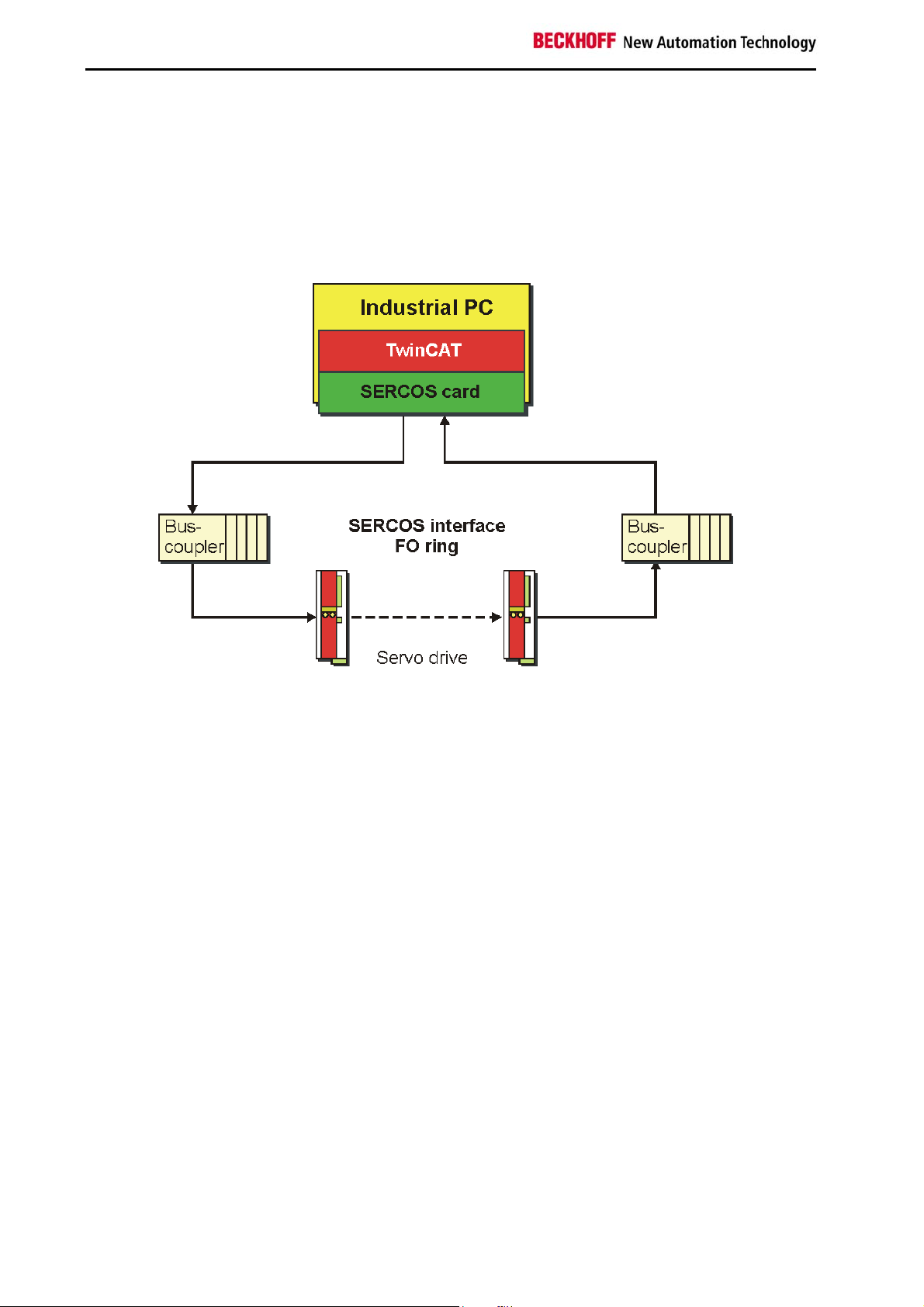
SERCOS control system
With TwinCAT as software PLC/NC, SERCOS cards, digital servo drives and Bus Terminals as I/O system, Beckhoff thus provides a complete PC-based control system for the SERCOS interface.
6 FC750x
Page 7

Product Overview
Hardware
The PCI cards for SERCOS interface FC7501 (single-channel) and FC7502 (double-channel) enable direct access
to the SERCON816 ASIC. The driver for these passive cards is incorporated into the TwinCAT software and allows optimum access to the SERCOS interface. There are no unnecessary restrictions with regard to the number
of bus devices and I/O data per device.
The power of TwinCAT comes into its own with this new interface generation:
• Up to 254 device (servo drives or I/O modules, e.g. Bus Terminals with Bus Coupler BK7500)
• No restriction regarding assignment and length of the I/O data
• Exact synchronisation between TwinCAT and SERCOS
• Cycle times up to 62.5 µs are possible
• Synchronous process data communication
• Master and slave mode can be parameterised by software
• It is possible to have two parallel fieldbus channels on one card (2x SERCON816)
• Synchronisation of both channels and other cards along with PC is possible
• Can read in bus configuration
FC7501 and FC7502 in revision B FC7501 and FC7502 in revision C
1. PCI bus interface
2. Socket for connecting the sync cable
11. SERCOS output for connecting the outgoing optical fiber for optical fiber ring A
12. SERCOS input for connecting the return optical fiber for optical fiber ring A
13. Diagnostics LED for optical fiber ring A
21. SERCOS output for connecting the outgoing optical fiber for optical fiber ring B
22. SERCOS input for connecting the return optical fiber for optical fiber ring B
23. Diagnostics LED for optical fiber ring B
The hatched components for SERCOS channel B are not populated on the single-channel FC7501.
Compared with revision B, revision C has a larger board corresponding to the standard height of PCI cards.
TwinCAT I/O provides configuration tools and Windows NT/2000 drivers for programs in any desired high level
language (DLLs) and for Visual Basic applications (ActiveX). Applications with OPC interfaces can access the
cards via an OPC server.
Diagnostics LED
The diagnostics LED of a fieldbus channel is on, if the data transfer on the optical fiber is disturbed.
FC750x 7
Page 8

Product Overview
Technical data
FC7501 FC7502
Fieldbus SERCOS interface
Number of field bus channels 1 2
Data transfer rate 2, 4, 8 or 16 MBaud
Synchronisation Synchronisation of several cards via ribbon cable
Bus devices 254 max. per channel
Cycle time all supported by SERCOS interface (from 62.5 µs)
Hardware diagnosis 1 LED per channel
Interface to the PC Plug and Play PCI Interface 32 bit, direct access to DPRAM
and SERCON816 register
Current consumption from the PCI bus typically 180 mA typically 285 mA
Dimensions approx. 95 x 120 mm
Permissible ambient temperature during operation 0° to 55 °C
Ordering information
Order designation Product
FC7501 SERCOS interface PCI card, single-channel
FC7502 SERCOS interface PCI card, double-channel
Z1003 FSMA plug with knurled nut for 1000 µm plastic fiber
Z1100 Plastic optical fiber, single core, 1000 µm
Z1101 Plastic optical fiber, single core, 1000 µm with protective PU cladding and Kevlar strain
relief
ZB7501 SERCOS master sync cable, for connecting SERCOS interface PCI cards of a PC
8 FC750x
Page 9

Installation
3. Installation
Installation of the SERCOS card in the PC
The SERCOS cards are supplied in ESD packaging. Follow the usual ESD guidelines
Warning
1. Before installing the SERCOS card, switch off the PC and any external power supplies, and separate the
PC from the mains.
2. Open the PC case.
3. Remove the protective caps of the optical fibre connections of the SERCOS card.
4. For a free PCI slot on the motherboard, remove the metal plate in the PC case.
5. Insert the SERCOS card into the free PCI slot and fix it with the screw or device provided.
Ensure that there is sufficient space between the SERCOS card and other PC components, so that the
Lightbus card cannot come into contact with other plug-in cards or memory components etc.
for handling PC cards during installation!
6. Close the PC case.
7. Connect the SERCOS cables with the optical fibre connections of the SERCOS card:
- Light grey: outgoing SERCOS cable
- Dark grey: return SERCOS cable
8. Connect the PC to the mains and switch it on.
9. After the PC has booted up, under Windows 2000 and Windows XP the Add Hardware Wizard will install a
PCI driver, in order to integrate the SERCOS card into the plug and play interface of the operating system. Under Windows NT 4.0, this driver is not required.
The SERCOS card does not require an external power supply. It is supplied directly from the PC via the PCI bus.
The power supply of the PC has to be adequate for meeting the power requirement of the SERCOS cards, particularly if several SERCOS cards are installed.
SERCOS master sync cable
If a PC with more than one SERCOS card is used, the cards should be connected via a SERCOS master sync
cable to ensure synchronisation:
• To this end, plug the ZB7501 sync cable into the sockets provided at the upper edge of the SERCOS
cards.
• Use the TwinCAT System Manager for specifying the operating mode of all channels of the SERCOS
cards to ensure synchronisation.
FC750x 9
Page 10

Installation
Installation of the PCI driver
After installation of the SERCOS card, Windows 2000, for example, comes up with the following message during
start-up:
The PCI driver for the SERCOS card is supplied with the Beckhoff TwinCAT automation software.
Follow the instructions of the Add Hardware Wizard.
Under Windows XP, the PCI driver is installed in the same way.
Under Windows NT 4.0, the PCI driver is not required.
Example for the resources of an FC750x under Windows2000.
(Control Panel / System / Hardware / Device Manager / TwinCAT PNP drivers / TwinCAT FC750x PCI driver /
Resources):
The PCI bus allocates an IRQ for the SERCOS card (IRQ9 in the example), although
Note
the IRQ is not used by the SERCOS card!
10 FC750x
Page 11

Configuration
4. Configuration
The FC7501 is a single-channel and the FC7502 a double-channel passive SERCOS card (SErial Real-time
COmmunication System) with PCI interface. They can be operated as Sercos masters and/or as Sercos slaves.
The Sercos SERCON816 ASIC is used. It supports not only 2 and 4 MBaud, but also 8 and 16 MBaud.
Context menu
Append Box... <Insert>
Adds Sercos slaves (boxes):
Supported boxes Description
BK7500 Bus Coupler
Sercos Axis Sercos Axis
Delete Device... <Del>
Removes the FC750x fieldbus card and all subsidiary elements from the I/O configuration.
Online Reset
Initiates an online reset of the Sercos master, so that the phase will switch to phase 0 and will then return to what
had previously been the current phase.
FC750x 11
Page 12

Configuration
The FC750x tab
PCI Slot / IRQ
Shows in which logical PCI slot the card was detected and which IRQ is assigned to it. The IRQ is unused.
Search...
Searches for all connected FC750x channels. Select those required. In the case of an FC7502 both channels A
and B appear. These behave in logical terms like two FC7501 cards.
PCI-Cfg...
In which the address of the FC750x is set in the lower memory area (below 1 MB) of the PC.
Scan the bus...
The Sercos ring is scanned here, and all devices found are added to the device. In the case of Beckhoff boxes the
configuration is read precisely.
Data rate
The Sercos baud rate is set here. 2 MBaud, 4 MBaud, 8 MBaud or 16 MBaud can be selected.
Transmitter power
The power of the transmitter is set here, depending on the length of optical fiber being used.
Operation mode
The FC750x can be operated as a Sercos master and as a Sercos slave. In either of these operating modes, the
card can be operated as the synchronous master (the PC and other synchronous devices receive their clock from
the sync master) or as a sync slave (the card, or the card channel, receives the synchronisation signal from the
other channel or from another card over the sync cable). There can only be one synchronous master within one
PC. If both channels of a FC7502 are used, then only the A-channel (the channel closest to the motherboard) can
be used as the sync master.
Start-up to Phase 4
If selected, then every time TwinCAT starts up, an attempt will be made to bring the Sercos bus into phase 4, and
thus to perform cyclical data exchange. If this option is not selected, the card will remain in phase 2. It will then
have to be placed into phase 4 at a later stage by ADS from, for example, the PLC.
12 FC750x
Page 13

Configuration
Check Timing
If selected, then in each cycle the exact real-time behaviour of access to the card is monitored. If not maintained
(actual values are read too early, or set values are written too late) then a corresponding counter located in the
process data is incremented. This monitoring has only a very small impact on the performance, so that there is no
disadvantage to using it in normal applications. In applications with very short cycle times and where performance
margins are very tight, however, it can be switched off.
Watchdog
The SERCON816 Sercos ASIC used has a hardware watchdog that monitors regular PC access, activating phase
0 if the accesses cease. The number of cycles that the watchdog will tolerate is given here. The watchdog is deactivated if the figure supplied is 0.
NC Access Time
A figure is given here for the time required by the NC in each cycle for reading the actual values and writing the set
values. This value is only used by the internal time slot calculation, so that possible time slot problems can be
seen in advance (cf. Check Timing Errors).
NC Shift Time
The NC shift time can be used to delay the time at which the NC begins to read the actual values. The value gives
the number of µs after the last AT. The default value of 50µs ensures in normal cases that even if there is a small
amount of jitter in the real-time system, the ATs, and therefore the actual values, have safely arrived at the master
before the NC takes action. If more than one Sercos ring is in use, it may be necessary to adjust this value, since
the NC accesses all the rings at more or less the same time, but the connected devices in particular rings mean
that the last ATs arrive at different times. Since the Sercos rings on the bus are synchronised in hardware, the
following rule applies: The NC shift time should be set on the various rings in such a way that the resulting tNcAccess time (see timing) is about the same on all the rings. In addition to this, the NC shift time should not be much
less than about 20 µs on any ring.
Cycle-Time(3-4)
The cycle time of the highest priority associated task is indicated here. This is used in phases 3 and 4.
Cycle-Time(0-2)
The cycle time in phases 0 to 2 is given here. This is used for the bus start-up.
The following values make it possible to influence the internal time slot calculation, to make modifications of a few
µs in the event of communication problems or loading difficulties. However, this should not be done without the
appropriate Sercos expertise, so that the effects can be estimated.
JT1 User
The value set here alters the jitter JT1 used in the internal time slot calculation.
JT2 User
The value set here alters the jitter JT2 used in the internal time slot calculation.
JTSCyc User
The value set here alters the jitter JTSCyc used in the internal time slot calculation.
T3 User
The value set here alters the time T3 used in the internal time slot calculation.
T4 User
The value set here alters the time T4 used in the internal time slot calculation.
FC750x 13
Page 14
Configuration
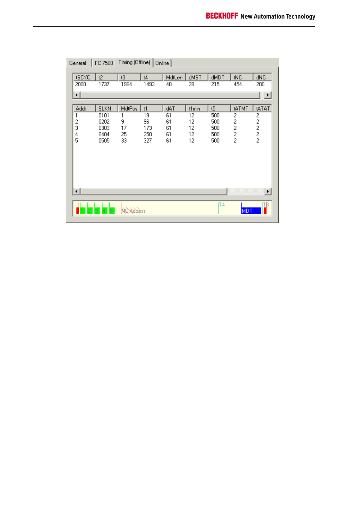
The Timing (Online/Offline) tab
The Timing tab provides internal details of the time slot calculation. A distinction is made between an online and
an offline mode, since parameters are also read from the devices and included in the calculation of the time slot. In
offline mode (TwinCAT is stopped) default values are used for the timing values that are normally read from the
devices, so that the result of this calculation can differ slightly from that obtained with the true values. The offline
calculation does however as a rule provide a very good estimate of the bus timing. In online mode (TwinCAT is
running and the Sercos Bus is in phase 3 or 4) the exact values are displayed, and provide the expert user with
very precise information about the timing on the bus.
The diagram in the lower section provides a good summary of the bus loading being generated, and over the capacity still available. A Sercos cycle is displayed between the two red master control telegrams (MST). After the
MST the devices first send their drive telegrams (green), and after the NC shift time the NC access time (dotted
region) starts, in which the NC accepts the actual values and transmits new set values. The subsequent clear region leading up to the Master Data Telegram (MDT, blue) indicates bus capacity that is still free, and can be used
for other devices or for additional data associated with the existing devices.
Not long after the MDT the master sends another MST, so starting the next cycle. Times T3 and T4 indicate when
the devices should all simultaneously accept the set values or acquire the actual values.
14 FC750x
Page 15

Configuration
The Online tab
The Online tab makes it possible to find the current phase of the Sercos ring and to change it. Three red dashes
"---" for the phase indicate a ring that is not closed. A phase indication like "2->3" indicates that a change of phase
is currently in progress, and that it is possible that this may take some time.
The DPRAM (online) tab
If TwinCAT is active, direct read access to the DPRAM of the fieldbus cards is provided for diagnostic purposes.
Following the SERCON816 DPRAM, the ASIC registers appear from address 0x1000.
FC750x 15
Page 16

Diagnosis
5. Diagnosis
Diagnosis Inputs
The FC750x has a variety of diagnostic variables available automatically. They describe the state of the card and
of the Sercos ring:
ActualPhase
The current phase of the Sercos ring is displayed.
RequestedPhase
The phase currently being requested (e.g. by the PLC) is displayed. The card or driver is presently attempting to
activate this phase.
SystemState
Gives more precise information about the current phase:
0xE001 = Phase 0
0xE002 = Phase 1
0xE003 = Phase 2
0xE004 = Phase 3
0xE005 = Phase 4
0xE008 = Break
0xE011 = Phase switch 0 -> 1
0xE012 = Phase switch 1 -> 2
0xE013 = Phase switch 2 -> 3
0xE014 = Phase switch 3 -> 4
SystemError
Indicates the current error state:
0x0000 = No error
0x8005 = Drive addresses are incorrect
0x8006 = HS-timeout (service channel)
0x8007 = Double AT-failure
0x8009 = Optical fibre bus is interrupted
0xD002 = Break
0xD003 = Switch from 2->3 failure (S-0-0127)
0xD004 = Switch from 3->4 failure (S-0-0128)
0xF001 = Configuration error (actual/nominal channel)
0xF002 = Error in the time slot calculation
0xF003 = Incorrect phase setting by the NC
0xF004 = Internal error
0xF005 = Error lifecounter
0xF008 = Double MDT-failure
0xF009 = Double MST-failure
0xF00A = Sync-In signal failure
16 FC750x
Page 17

Diagnosis
TimingError1
A counter that is incremented if the NC accesses the actual values too early ("Check timing" must have been selected).
TimingError2
A counter that is incremented if the NC supplies new set values too late ("Check timing" must have been selected).
RD istErrorCnt
An error counter that counts telegrams received in a damaged state (cf. RDIST in the SERCON816 Reference
Manual). The cause can be an incorrect baud rate.
FibBrErrorCnt
An error counter that counts telegrams received in a damaged state (cf. FIBBR in the SERCON816 Reference
Manual). The cause can be an incorrect baud rate.
RRerrErrorCnt
An error counter that counts telegrams that have been lost or that are received at the wrong time (cf. RERR in the
SERCON816 Reference Manual).
MstLateErrorCnt
An error counter that counts MSTs that are received too late (cf. MSTLATE in the SERCON816 Reference Manual).
MstEarlyErrorCnt
An error counter that counts MSTs that are received too early (cf. MSTEARLY in the SERCON816 Reference Manual).
FC750x 17
Page 18

Appendix
6. Appendix
Support and Service
BECKHOFF and their partners around the world offer comprehensive support and service, making available fast and
competent assistance with all questions related to BECKHOFF products and system solutions.
BECKHOFF Support
Support offers you comprehensive technical assistance, helping you no only with the application of individual
BECKHOFF products, but also with other, wide-ranging services:
• world-wide support
• design, programming and commissioning of complex automation systems
• and extensive training program for BECKHOFF system components
Hotline: +49(0)5246/963-157
Fax: +49(0)5246/963-199
e-mail: support@beckhoff.com
BECKHOFF Service
The BECKHOFF Service Center supports you in all matters of after-sales service:
• on-site service
• repair service
• spare parts service
• hotline service
Hotline: +49(0)5246/963-460
Fax: +49(0)5246/963-479
e-mail: service@beckhoff.com
You will find further support and service addresses on our Internet pages under http://www.beckhoff.com. You will
also find documentation for BECKHOFF components there.
BECKHOFF Headquaters
BECKHOFF Industrie Elektronik
Eiserstr. 5
33415 Verl
Germany
Phone:
Fax: +49(0)5246/963-198
e-mail: info@beckhoff.com
The addresses of BECKHOFF's branch offices and representatives round the world can be found on her internet
pages:
http://www.beckhoff.com
You will also find further documentation for BECKHOFF components there.
18 FC750x
+49(0)5246/963-0
 Loading...