

Page 1
Beckhoff
PC Fieldbus card
CX Fieldbus module
DeviceNet:
FC520x / CX1500-x520
Version: 1.1
22.04.2004
Page 2

Page 3

FC520x / CX1500-x520
Eiserstraße 5 / D-33415 Verl / Telefon 05246/963-0 / Telefax 05246/963-149
Please note the following
Target group
Safety requirements
This description is only intended for the use of trained specialists in control
and automation engineering who are familiar with the applicable national
standards.
The responsible staff must ensure that the application or use of the products described satisfy all the requirements for safety, including all the relevant laws, regulations, guidelines and standards.
The documentation has been prepared with care. The products described are,
however, constantly under development. For that reason the documentation is not
in every case checked for consistency with performance data, standards or other
characteristics, and does not represent an assurance of characteristics in the sense
of § 459, Para. 2 of the German Civil Code. In the event that it contains technical or
editorial errors, we retain the right to make alterations at any time and without warning. No claims for the modification of products that have already been supplied may
be made on the basis of the data, diagrams and descriptions in this documentation.
This manual is copyrighted. Any reproduction or third party use of this protected
©
publication, whether in whole or in part, without the written permission of Elektro
Beckhoff GmbH, is forbidden.
2
BECKHOFF FC520x / CX1500-x520
Page 4

FC520x / CX1500-x520
Eiserstraße 5 / D-33415 Verl / Telefon 05246/963-0 / Telefax 05246/963-149
3
Table of Contents
1 FOREWORD .............................................................................................................4
1.1
Introduction ..................................................................................................................................4
1.2
Safety Instructions.......................................................................................................................5
1.3
Version of the Documentation....................................................................................................5
2 PRODUCT OVERVIEW.............................................................................................6
2.1
Beckhoff FC520x: Technical Documentation............................................................................6
2.2
Beckhoff CX1500-x520: Technical Documentation ..................................................................8
2.3
DeviceNet Introduction..............................................................................................................10
2.4
Hardware Description................................................................................................................11
2.5
DeviceNet Connector.................................................................................................................13
3 FITTING AND WIRING............................................................................................14
3.1
Installation ..................................................................................................................................14
3.2
Wiring the Bus System..............................................................................................................15
4 PARAMETERISATION AND COMMISSIONING....................................................18
4.1
Configuration: TwinCAT System Manager..............................................................................18
4.2
DeviceNet Device .......................................................................................................................19
4.3
DeviceNet Slave .........................................................................................................................26
4.4
DeviceNet Box............................................................................................................................29
5 ERROR HANDLING AND DIAGNOSIS..................................................................40
5.1
LEDs............................................................................................................................................40
5.2
Device Diagnostics ....................................................................................................................42
5.3
Box Diagnostics.........................................................................................................................45
6 APPENDIX..............................................................................................................49
6.1
Support and Service ..................................................................................................................49
BECKHOFF FC520x / CX1500-x520
Page 5

FC520x / CX1500-x520
Eiserstraße 5 / D-33415 Verl / Telefon 05246/963-0 / Telefax 05246/963-149
4
1 Foreword
1.1 Introduction
The purpose of this document is to provide DeviceNet Specific Information needed to set up a DeviceNet
Network with Beckhoff FC520x / CX1500-x520 DeviceNet Interface units. From DeviceNet point of view
both units have the same functionalities. Therefore, this documentation serves for both.
Beside the Product Overview it shows the DeviceNet Configuration and Diagnostic Data of Beckhoff’s
TwinCAT System Manager using a Beckhoff DeviceNet Interface FC520x or CX1500-x520. It is intended
for the usage of Master and Slave Interfaces and describes the meaning of the diagnostic inputs and
explains the troubleshooting for the specific errors.
BECKHOFF FC520x / CX1500-x520
Page 6

FC520x / CX1500-x520
Eiserstraße 5 / D-33415 Verl / Telefon 05246/963-0 / Telefax 05246/963-149
5
1.2 Safety Instructions
Safety Rules
The responsible staff must ensure that the application or use of the products described satisfy all the requirements for safety
State at Delivery
All the components are supplied in particular hardware and software configurations appropriate for the
application. Modifications to hardware or software configurations other than those described in the documentation are not permitted, and nullify the liability of Elektro BECKHOFF GmbH.
Personal Qualification
This description is only intended for the use of trained specialists in control and automation engineering
who are familiar with the applicable national standards.
, including all the relevant laws, regulations, guidelines and standards.
1.3 Version of the Documentation
Version
1.0 Preliminary Version, initial release
1.1 Added chapters:
Changes
- Product Overview
- Fitting and Wiring
- Appendix
BECKHOFF FC520x / CX1500-x520
Page 7
FC520x / CX1500-x520
Eiserstraße 5 / D-33415 Verl / Telefon 05246/963-0 / Telefax 05246/963-149
2 Product Overview
2.1 Beckhoff FC520x: Technical Documentation
6
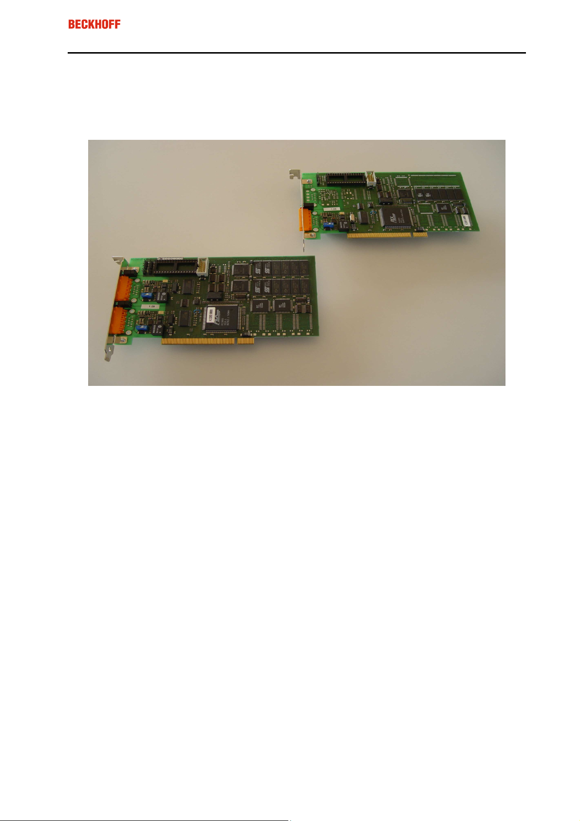
The FC5201 and FC5202 PC plug-in cards link the PC to a DeviceNet network. They can act as master
or as slave modules. The PCI bus interface ensures both high transmission rates to the PC and fully
automatic configuration of the cards in the PC hardware. The DeviceNet cards provide a powerful implementation of the protocol, offering many desirable features:
•
One (FC5201) or two (FC5202) DeviceNet channels, each with its own processor, memory, etc.
•
All DeviceNet I/O modes are supported: polling, change of state, cyclic, strobed
•
Optionally two DeviceNet channels in parallel on one card are possible
•
Powerful parameter and diagnostics interface
•
The error management for each bus user is freely configurable
•
It is possible to read the bus configuration and automatically assign the "eds" files
•
Integrated bus loading display
•
CAN interfaces are electrically isolated
BECKHOFF FC520x / CX1500-x520
Page 8

FC520x / CX1500-x520
Eiserstraße 5 / D-33415 Verl / Telefon 05246/963-0 / Telefax 05246/963-149
Technical Data
Technical Data
Number of Fieldbus Channels
Transmission Rate
Interface to the PC
Bus Interface
FC5201 FC5202
1 2
125, 250, 500 kbaud
plug-and-play PCI interface 32 bit with 4 kbytes DPRAM
per channel
open style connector 5-pin according to DeviceNet specification, galvanically isolated. Card comes with connector.
Bus nodes
Process image
Communication
Termination Resistor
Hardware diagnostics
Dimensions
Operating temperature
per channel: max. 63 slaves
total max. 3 kbyte input and output data
master and slave functionality
Switchable
2 LEDs per channel
approx. 106 x 175 mm
0 °C ... 55 °C
7
BECKHOFF FC520x / CX1500-x520
Page 9
FC520x / CX1500-x520
Eiserstraße 5 / D-33415 Verl / Telefon 05246/963-0 / Telefax 05246/963-149
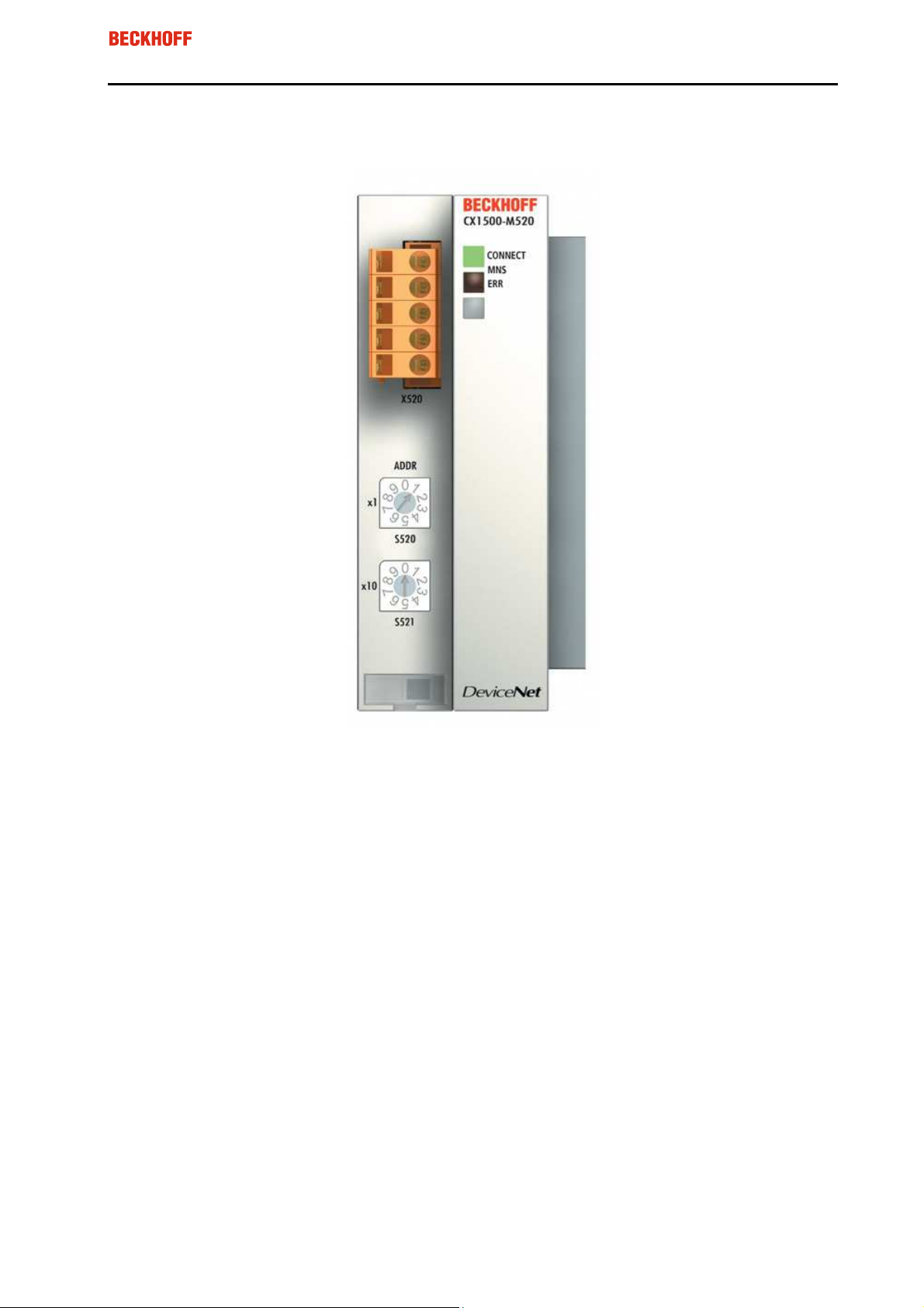
2.2 Beckhoff CX1500-x520: Technical Documentation
8
The CX1500-x520 links the CPU to a DeviceNet network. The CX1500-M520 can act as master, the
CX1500-B520 as slave module. The DeviceNet interface provides a powerful implementation of the protocol, offering many desirable features:
•
All DeviceNet I/O modes are supported: polling, change of state, cyclic, strobed
•
Powerful parameter and diagnostics interface
•
The error management for each bus user is freely configurable
•
It is possible to read the bus configuration and automatically assign the "eds" files
•
Integrated bus loading display
BECKHOFF FC520x / CX1500-x520
Page 10

FC520x / CX1500-x520
Eiserstraße 5 / D-33415 Verl / Telefon 05246/963-0 / Telefax 05246/963-149
Technical Data
Technical Data
Number of Fieldbus Channels
Transmission Rate
Interface to the CPU
Bus connectiom
Bus Nodes
Communication
Dimensions (W x H x D)
Weight approx.
Operating temperature
Storage temperature
Relative humidity
Vibration/shock resistance
EMC resistance burst/ESD
Protection class
CX1500-M520 CX1500-B520
1 1
125, 250, 500 kbaud
ISA plug and play, 2 kbyte DPRAM
open style connector 5-pin according to DeviceNet specification
max. 63 slaves
master functionality
38 mm x 100 mm x 91 mm
190 g
0 °C ... +55 °C
-25 °C ... +85 °C
95%, no condensation
conforms to IEC 68-2-6/IEC 68-2-29
conforms to EN 50082 (ESD, burst)/EN 50081
IP 20
max. 63 slaves
slave functionality
9
BECKHOFF FC520x / CX1500-x520
Page 11
FC520x / CX1500-x520
Eiserstraße 5 / D-33415 Verl / Telefon 05246/963-0 / Telefax 05246/963-149
10
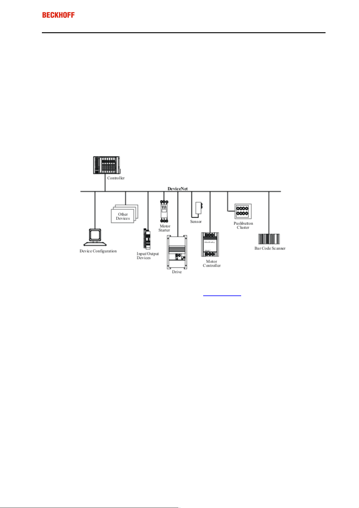
2.3 DeviceNet Introduction
DeviceNet is an open system based on CAN, developed by Bosch a few years ago. CAN was primarily
intended for the transfer of data within automobiles, and millions on CAN Chips have since been installed.
The disadvantage of using CAN in automation technology is that it does not define an application layer. It
specifies only the physical layer and data security layer.
DeviceNet specifies a uniform application layer and this makes it possible to use the CAN protocol for
industrial applications. ODVA (the open DeviceNet Vendor Association) is an independent association
which supports Manufactures and users of the DeviceNet system. ODVA ensures that all of the devices
which conform to the specification can operate together in one system, regardless of their manufacturer.
Example of DeviceNet in use:
For more details see the DeviceNet Specification or look at www.odva.org, the official Internet address of
the Open DeviceNet Vendor Association (ODVA).
BECKHOFF FC520x / CX1500-x520
Page 12
Socket for Flash
-
Disk
Devic
e
Net
Devic
e
Net
FC520x / CX1500-x520
Eiserstraße 5 / D-33415 Verl / Telefon 05246/963-0 / Telefax 05246/963-149
11
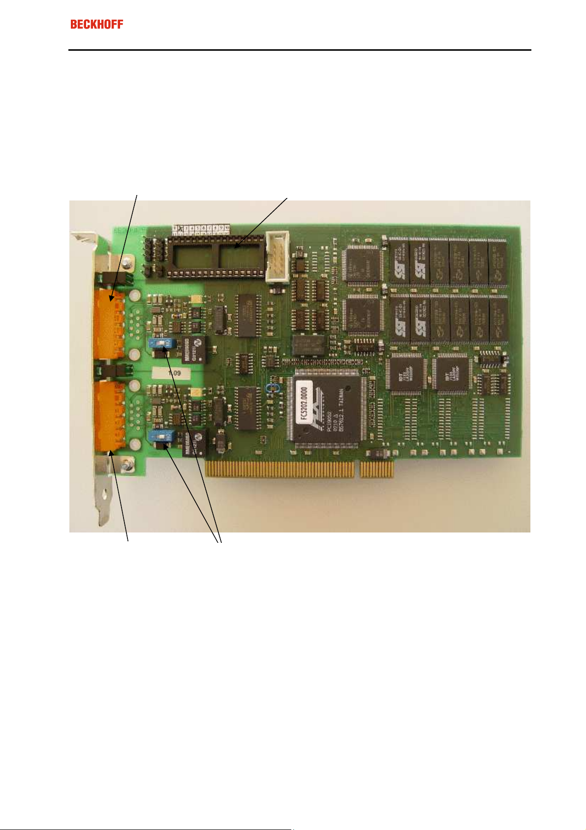
2.4 Hardware Description
2.4.1 FC520x - Overview
On the FC520x card there are DeviceNet / CAN termination resistors (120 Ohms). They can be activated
with a DIP-Switch close to the DeviceNet Connector.
Channel B
B
A
Channel A
DIP-Switch for terminating resistor (120 Ohm) for
each channel
BECKHOFF FC520x / CX1500-x520
Page 13
FC520x / CX1500-x520
Eiserstraße 5 / D-33415 Verl / Telefon 05246/963-0 / Telefax 05246/963-149
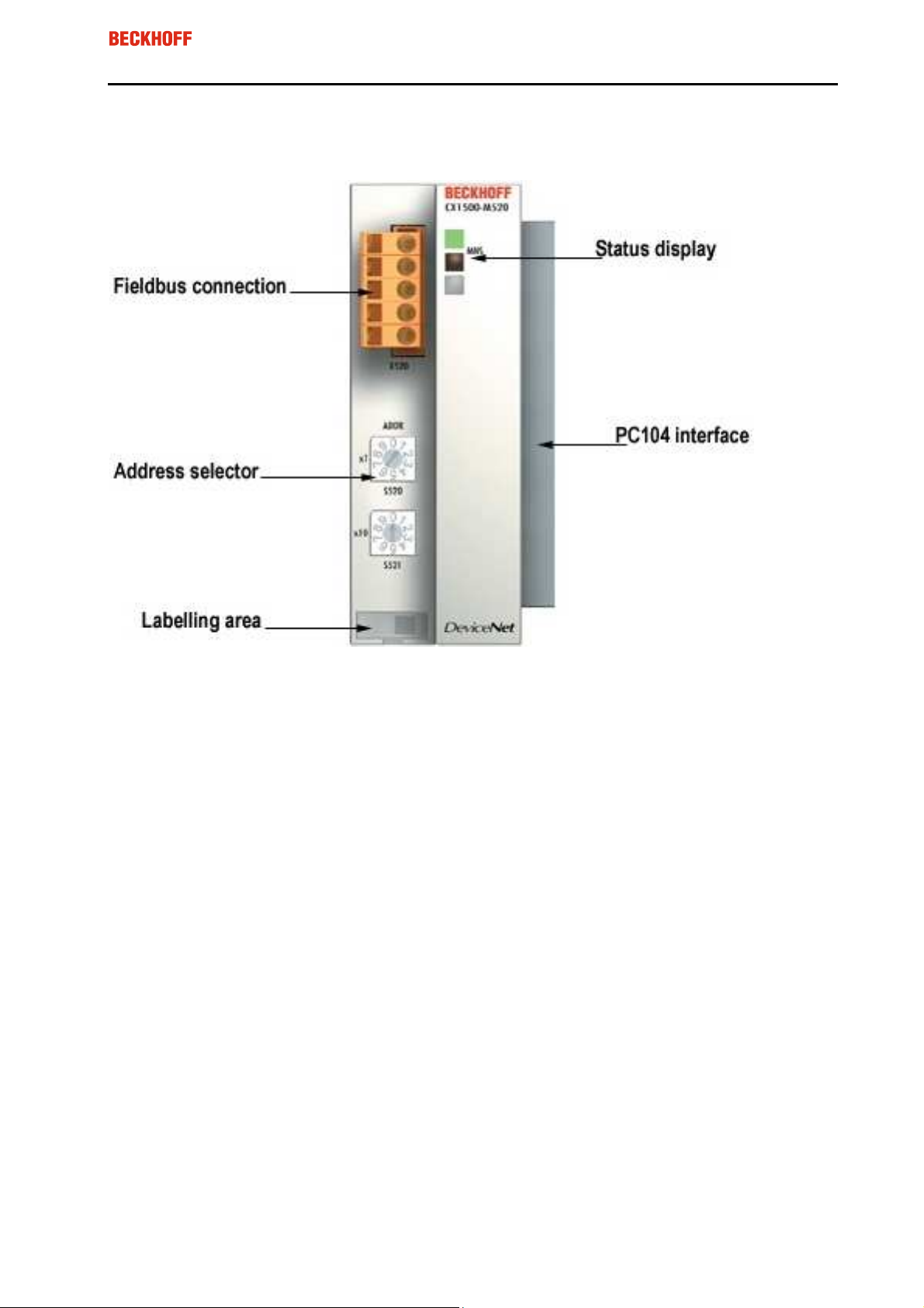
2.4.2 CX1500-x520 - Overview
12
Address Selector
With the CX1500-M520, the MAC-Id / Address is set within the TwinCAT System Manger
With the CX1500-B20, the MAC-Id / Address is set with the Address selector
BECKHOFF FC520x / CX1500-x520
Page 14
FC520x / CX1500-x520
Eiserstraße 5 / D-33415 Verl / Telefon 05246/963-0 / Telefax 05246/963-149
13
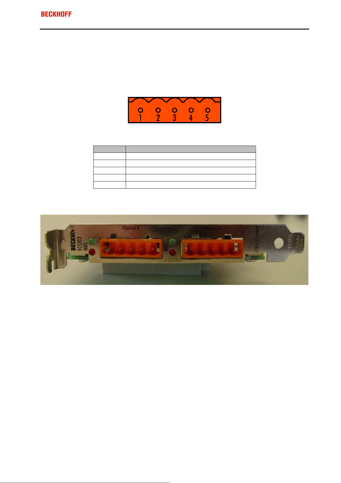
2.5 DeviceNet Connector
To connect the DeviceNet Bus cable a 5-pin socket for each channel is mounted on the DeviceNet units.
Note: It is mandatory to connect the DeviceNet Voltage to the Connector/System
FC520x:
DeviceNet Socket on FC520x / CX1500-x520
Pinout Description
1 V+ (24 Volt)
2 CAN-High
3 Shield
4 CAN-Low
5 V-
Channel B Channel A
5 4 3 2 1 5 4 3 2 1
BECKHOFF FC520x / CX1500-x520
Page 15
Devic
e
Net
Devic
e
Net
FC520x / CX1500-x520
Eiserstraße 5 / D-33415 Verl / Telefon 05246/963-0 / Telefax 05246/963-149
3 Fitting and Wiring
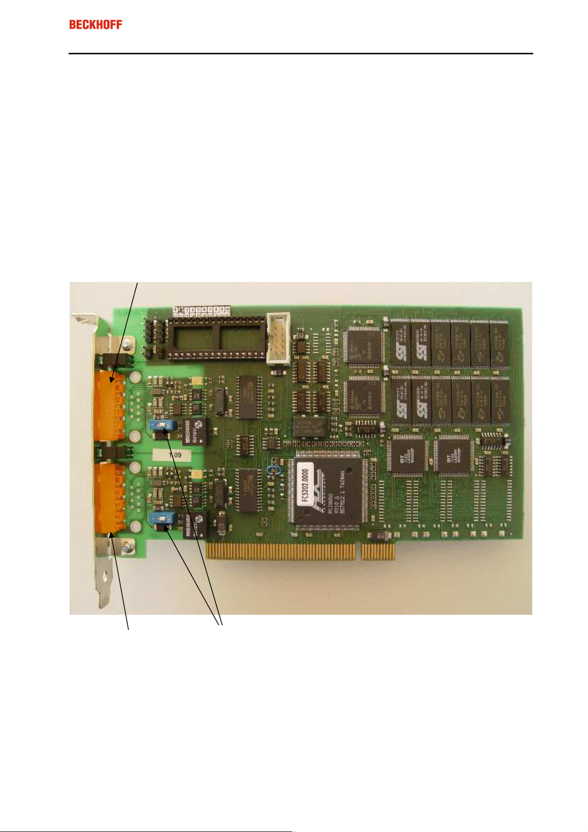
3.1 Installation
3.1.1 FC520x
Note:
Fieldbus PCI cards may only be fitted by qualified personnel in accordance and the following points
must be observed
•
In order to protect the card from electrostatic discharge the user must be discharged before han-
dling the card or the PC.
•
Before opening the PC housing it must be switched off, and the mains plug must be removed.
Channel B
14
B
A
It may be necessary before fitting to set the Dip-Switch in order to activate the internal CAN / DeviceNet
bus terminating resistors. The card can be fitted into any free PCI slot. Ensure that the PCI bus connector
is making good contact, and that the module is seated firmly. Fasten the module to the PC slot housing
with the fixing screw.
Channel A
DIP-Switch for terminating resistor (120 Ohm) for
each channel
BECKHOFF FC520x / CX1500-x520
Page 16
FC520x / CX1500-x520
Eiserstraße 5 / D-33415 Verl / Telefon 05246/963-0 / Telefax 05246/963-149
15
3.2 Wiring the Bus System
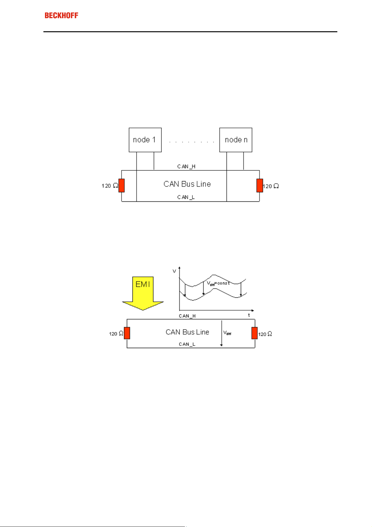
3.2.1 CAN / DeviceNet topology
CAN / DeviceNet is a 2-wire bus system, to which all participating devices are connected in parallel (i.e.
using short drop lines). The bus must be terminated at each end with a 120 (or 121) Ohm terminating
resistor to prevent reflections. This is also necessary even if the cable lengths are very short!
Since the CAN signals are represented on the bus as the difference between the two levels, the CAN
leads are not very sensitive to incoming interference (EMI): Both leads are affected, so the interference
has very little effect on the difference.
BECKHOFF FC520x / CX1500-x520
Page 17

FC520x / CX1500-x520
Eiserstraße 5 / D-33415 Verl / Telefon 05246/963-0 / Telefax 05246/963-149
16
3.2.2 Bus Length
The maximum length of a CAN bus is primarily limited by the signal transit time. The multi-master bus
access procedure (arbitration) requires signals to reach all the nodes at effectively the same time (before
the sampling within a bit period). Since the signal transit times in the CAN connecting equipment (transceivers, opto-couplers, CAN controllers) are almost constant, the line length must be chosen in accordance with the baud rate:
For the DeviceNet use of the CAN Bus following Baud Rates and Bus Lengths are specified:
BaudRate
500 kbit/s
250 kbit/s
125 kbit/s
Bus Length
< 100 m
< 250 m
< 500 m
3.2.3 Drop-Lines
Drop lines must always be avoided as far as possible, since they inevitably cause reflections. The reflections caused by drop lines are not however usually critical, provided they have decayed fully before the
sampling time. In the case of the bit timing settings selected in the bus couplers it can be assumed that
this is the case, provided the following drop line lengths are not exceeded (according to DeviceNet Specification):
BaudRate Drop line length Total length of all drop lines
500 kbit/s
250 kbit/s
125 kbit/s
< 6 m
< 6 m
< 6 m
< 39 m
< 78 m
< 156 m
Drop lines must not have terminating resistors.
Star Hub (Multiport Tap)
Shorter drop line lengths must be maintained with passive distributors ("multiport taps"), such as the
Beckhoff ZS5052-4500 Distributor Box. The following table indicates the maximum drop line lengths and
the maximum length of the trunk line (without the drop lines):
Note: These values are recommended by Beckhoff
BaudRate Drop line length with multi-
port topology
500 kbit/s
250 kbit/s
125 kbit/s
< 1,2 m
< 2,4 m
< 4.8 m
Trunk line length (without drop
lines)
< 66 m
< 120 m
< 310 m
BECKHOFF FC520x / CX1500-x520
Page 18

FC520x / CX1500-x520
Eiserstraße 5 / D-33415 Verl / Telefon 05246/963-0 / Telefax 05246/963-149
17
3.2.4 DeviceNet Cable – ZB5200
The ZB5200 cable material corresponds to the DeviceNet specification. The ready-made ZK1052-xxxxxxxx bus cables for the Fieldbus Box modules are made from this cable material. It has the following
specification:
•
2 x 2 x 0.34 mm² (AWG 22) twisted pairs
•
double screened braided screen with filler strand
•
characteristic impedance (1 MHz): 126 Ohm
•
conductor resistance 54 Ohm/km
•
sheath: grey PVC, external diameter 7.3 mm
•
printed with "InterlinkBT DeviceNet Type 572" as well as UL and CSA ratings
•
stranded wire colours correspond to the DeviceNet specification
•
UL recognised AWM Type 2476 rating
•
CSA AWM I/II A/B 80°C 300V FT1
•
corresponds to the DeviceNet "Thin Cable" specification
Cable colours
Description DeviceNet-cable colour
V+ (24 Volt) Red
CAN-High White
Shield Filler strand
CAN-Low Blue
V- Black
BECKHOFF FC520x / CX1500-x520
Page 19

FC520x / CX1500-x520
Eiserstraße 5 / D-33415 Verl / Telefon 05246/963-0 / Telefax 05246/963-149
18
4 Parameterisation and Commissioning
4.1 Configuration: TwinCAT System Manager
The TwinCAT System Manager Tool is used to configure the FC520x DeviceNet PCI card and the
CX1500-x520 Fieldbus Modules. The System Manager provides a representation of the number of programs of the TwinCat PLC systems, the configuration of the axis control and of the connected I/O channels as a structure, and organises the mapping of the data traffic.
For applications without TwinCAT PLC or NC, the TwinCAT System Manager Tool configures the programming interfaces for a wide range of application programs:
•
ActiveX control (ADS-OCX) for e.g. Visual Basic, Visual C++, Delphi, etc.
•
DLL interface (ADS-DLL) for e.g. Visual C++ projects
•
Script interface (ADS script DLL) for e.g. VBScript, JScript, etc.
4.1.1 System Manager – Features
•
- Bit-wise association of server process images and I/O channels
•
- Standard data formats such as arrays and structures
•
- User defined data formats
•
- Continuous variable linking
•
- Drag and Drop
•
- Import and export at all levels
4.1.2 Configuration by means of the TwinCAT System Manager
The procedure, and the configuration facilities in the System Manager are described within the next chapters.
BECKHOFF FC520x / CX1500-x520
Page 20

FC520x / CX1500-x520
Eiserstraße 5 / D-33415 Verl / Telefon 05246/963-0 / Telefax 05246/963-149
19
4.2 DeviceNet Device
4.2.1 Append Device
Appending a Device can either be executed by running the “Scan-Devices” routine of the TwinCAT System Manager or by selecting manually the Device out of the list of possible DeviceNet Devices.
Appending the Device manually is done by e.g. selecting the “IO-Devices” and apply the right MouseButton:
BECKHOFF FC520x / CX1500-x520
Page 21

FC520x / CX1500-x520
Eiserstraße 5 / D-33415 Verl / Telefon 05246/963-0 / Telefax 05246/963-149
20
4.2.1.1 Apend the FC520x as DeviceNet Slave
If the FC520x-Device is appended manually, all settings for the DeviceNet Slave are configured automatically.
If the FC520x-Device is appended with the “Scan-Devices” routine, TwinCAT should not search for new
Boxes. The scan has to be stopped after detecting the FC520x and the following steps have to be done:
1. Switch the DeviceNet-Mode to “Slave”
2. Append Box for FC520x DeviceNet Slave Port
BECKHOFF FC520x / CX1500-x520
Page 22

FC520x / CX1500-x520
Eiserstraße 5 / D-33415 Verl / Telefon 05246/963-0 / Telefax 05246/963-149
4.2.2 Configuration
4.2.2.1 FC520x / CX1500-x520
FC520x
21
PCI Slot/Irq
: Shows in which logical PCI slot the card was detected and which IRQ is assigned to it. The
IRQ is unused.
Search
: Searches for all connected FC520x channels. Select those required. In the case of an FC5202
both channels A and B appear. These behave in logical terms like two FC5201 cards.
Upload Configuration:
Scans the DeviceNet network and adds all found devices (boxes cannot be
added). In the case of Beckhoff boxes, reads the configuration precisely. Searches external devices to
find the corresponding EDS file.
Firmware
Firmware Update
MAC-ID
: Shows the current firmware version of the FC520x.
: Update the FC520x card firmware version here.
: Each DeviceNet device requires a unique station number – MAC-ID (Medium Access Identifier)-
including the master.
Baudrate
: Set the DeviceNet Baudrate here. Select one of the following: 125kBaud, 250 kBaud and 500
kBaud
Cycle Time
IO-Cycle Time
: Displays the cycle time of the corresponding highest priority task.
: Sets the cycle time for the I0 connections. This value is used as the default value for
newly added boxes.
Heartbeat Time
: not supported
BECKHOFF FC520x / CX1500-x520
Page 23

FC520x / CX1500-x520
Eiserstraße 5 / D-33415 Verl / Telefon 05246/963-0 / Telefax 05246/963-149
CX1500-x520
22
Address
Search
Upload Configuration
: Address of CX1500-x520
: Searches for all connected CX1500-x520 channels.
: Scans the DeviceNet network and adds all found devices (boxes cannot be
added). In the case of Beckhoff boxes, reads the configuration precisely. Searches external devices to
find the corresponding EDS file.
Firmware
Firmware Update
MAC-ID
: Shows the current firmware version of the CX1500-x520.
: Update the CX1500-x520 card firmware version here.
: Each DeviceNet device requires a unique station number – MAC-ID (Medium Access Identifier)-
including the master
Note:
With the CX1500-M520, the MAC-Id / Address is set within the TwinCAT System Manger
With the CX1500-B20, the MAC-Id / Address is set with the Address selector on the module
Baudrate
: Set the DeviceNet Baudrate here. Select one of the following: 125kBaud, 250 kBaud and 500
kBaud
Cycle Time
IO-Cycle Time
: Displays the cycle time of the corresponding highest priority task.
: Sets the cycle time for the I0 connections. This value is used as the default value for
newly added boxes.
Heartbeat Time
: not supported
BECKHOFF FC520x / CX1500-x520
Page 24

FC520x / CX1500-x520
Eiserstraße 5 / D-33415 Verl / Telefon 05246/963-0 / Telefax 05246/963-149
4.2.2.2 ADS
23
The ADS section provides information about Port-Number and NetIDs used for TwinCAT ADS Commands.
BECKHOFF FC520x / CX1500-x520
Page 25

FC520x / CX1500-x520
Eiserstraße 5 / D-33415 Verl / Telefon 05246/963-0 / Telefax 05246/963-149
4.2.2.3 GeneralDiag
24
Cycle-Time
BusLoad
Failed Cycle Counter
: CycleTime of the DeviceNet-FW
.: DeviceNet Bus Load in %
: This counter increments each time when at the beginning of theTwinCAT-Cycle
the last Bus-Cycle was not finished. If the Cycle-Time of the DeviceNet-FW exceeds the CycleTime of the
corresponding highest priority task this counter is incremented.
If the Failed Cycle Counter is incremented permanently after the Network-Start, the following has to be
checked:
- Cycle-time of the corresponding highest priority task should may adapted to the max. Cycle-Time
of the DeviceNet-FW
- Network-Load for the DeviceNet-Master has to be checked. There are may too much DeviceNet
Boxes connected to the DeviceNet Master, which could cause a heavy CycleTime for the DeviceNet Master FW.
- Check IO-Cycle Times of attached DeviceNet-Boxes. Some of the IO-Cyle Times of the DeviceNet Boxes are may to fast, which could cause a heavy CycleTime for the DeviceNet Master
FW.
- Check DeviceNet Bus-Load
BECKHOFF FC520x / CX1500-x520
Page 26

FC520x / CX1500-x520
Eiserstraße 5 / D-33415 Verl / Telefon 05246/963-0 / Telefax 05246/963-149
25
4.2.2.4 BoxStates
The BoxState section shows the actual state of the connected Boxes for the DeviceNet-Master unit. The
BoxState is corresponding to the MAC-State of each DeviceNet-Box:
BECKHOFF FC520x / CX1500-x520
Page 27

FC520x / CX1500-x520
Eiserstraße 5 / D-33415 Verl / Telefon 05246/963-0 / Telefax 05246/963-149
26
4.3 DeviceNet Slave
The DeviceNet Slave Functionality is the same for FC520x and CX1500-B520.
Diagnostic Data is corresponding to the explanations of the Diagnostic Inputs for DeviceNet Devices and
DeviceNet Boxes.
The DeviceNet Slave Port is Pre-Initialized using the IO-Mode Polling. Other IO-Modes can be selected
referring the DeviceNet rules by disabling/enabling of the IO-Modes. The Inputs and Outputs Data-Length
is set to 8 Bytes per Default. The Data-Lengths can be adjusted as used by the application.
BECKHOFF FC520x / CX1500-x520
Page 28

FC520x / CX1500-x520
Eiserstraße 5 / D-33415 Verl / Telefon 05246/963-0 / Telefax 05246/963-149
27
4.3.1 IO-Mode-Selection
The DeviceNet Slave Port is Pre-Initialized using the IO-Mode Polling. Other IO-Modes can be selected
referring the DeviceNet rules by disabling/enabling of the IO-Modes:
If there are still Inputs/Outputs disabled after selecting other IO-Modes, the referring DeviceNet rules for
the IO-Modes are not valid:
BECKHOFF FC520x / CX1500-x520
Page 29

FC520x / CX1500-x520
Eiserstraße 5 / D-33415 Verl / Telefon 05246/963-0 / Telefax 05246/963-149
28
4.3.2 Input/Output Configuration
The Inputs and Outputs can be configured by inserting Variables. This can be done according to the need
of the application.
Within DeviceNet, data-lengths are seen as Byte-Steams. The total Number of Bytes have to be configured in the DeviceNet Masters Input and Output Size for its DeviceNet Slaves:
Note: The Data-Length for Inputs and Outputs should not exceed 255 Bytes
BECKHOFF FC520x / CX1500-x520
Page 30

FC520x / CX1500-x520
Eiserstraße 5 / D-33415 Verl / Telefon 05246/963-0 / Telefax 05246/963-149
29
4.4 DeviceNet Box
4.4.1 Append Box
Appending a DeviceNet Box can either be executed by running the “Scan-Boxes” routine of the TwinCAT
System Manager or by selecting manually the Device out of the list of possible DeviceNet Devices.
Appending the DeviceNet-Box manually is done by e.g. selecting the “DeviceNet-Devices” and apply the
right Mouse-Button:
The “Insert-Box” Menu shows the list of available Devices:
The list is generated with the Information of the EDS-Files stored in:
..\TwinCAT\IO\DeviceNet
BECKHOFF FC520x / CX1500-x520
Page 31
FC520x / CX1500-x520
Eiserstraße 5 / D-33415 Verl / Telefon 05246/963-0 / Telefax 05246/963-149
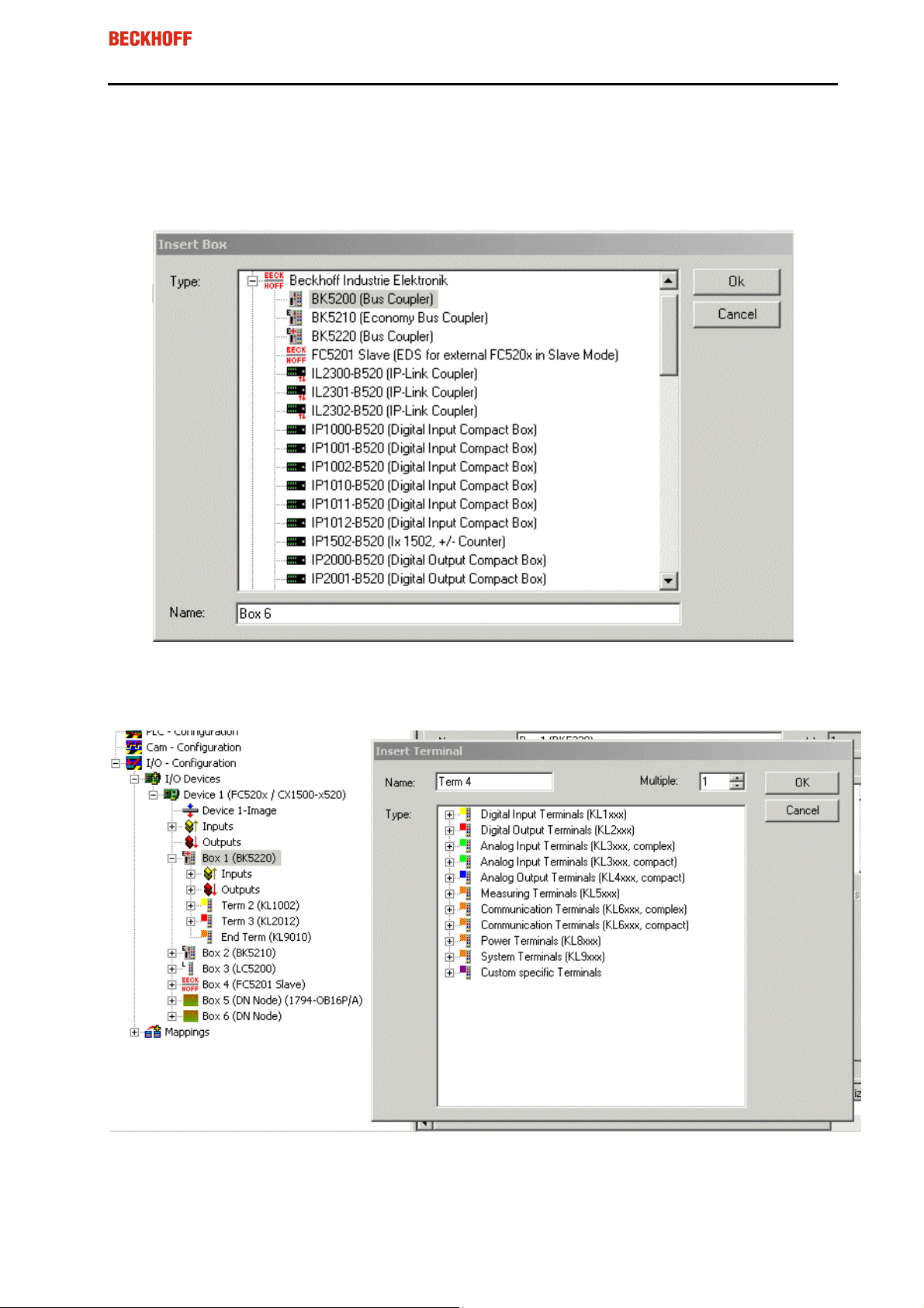
4.4.1.1 Insert BK52x0 / IX-B52x
Select the BK52x0 /v Ix-B52x within the list of supported Beckhoff-Devices:
30
Select the Terminals to be configured for the couplers:
BECKHOFF FC520x / CX1500-x520
Page 32

FC520x / CX1500-x520
Eiserstraße 5 / D-33415 Verl / Telefon 05246/963-0 / Telefax 05246/963-149
4.4.1.2 Insert DeviceNet Node
Inserting a DeviceNet Node is done by the following steps to be executed:
1. Select a DeviceNet node within the Miscellaneous section
31
2. Select the EDS-File for the Box to be inserted:
BECKHOFF FC520x / CX1500-x520
Page 33

FC520x / CX1500-x520
Eiserstraße 5 / D-33415 Verl / Telefon 05246/963-0 / Telefax 05246/963-149
4.4.2 Configuration
4.4.2.1 BK52x0 / IX-B52x / DeviceNet Node
BK52x0 / IX-B52x
32
MAC Id
: Sets the MAC-ID of the DeviceNet participant (between 0 and 63). This value must comply with
the value set at the Bus Coupler.
Cycle Time
: Sets the cycle time for the I0 connection (Polled and Bit-Strobe). This value is added to the
Expected Packet Rate (EPR) attributes of the DeviceNet slave and acts as a timeout monitor for IO connections.
Electronic Key
: Serves to check the devices within the network at the system StartUp. The electronic
key is read from the devices at every system StartUp and compared with the saved configuration.
Polled
: Produced/Consumed: Activation of the ”Polling” operating mode, cyclical writing and reading of IO
data. Setting of the data content of the data transmitted via the polled IO connections. You can choose
from digital data, analogue data or both. The selection depends upon the BK52xx terminal arrangement.
Bit-Strobed
: Produced/Consumed: Activation of the ”Bit Strobe” Operating Mode. With a broadcast message all nodes are requested to send their bit strobe message (up to 7 bytes input or status data). Setting
of the data content of the data transmitted via the bit-strobed IO connections. You can choose between
digital data or diagnostic data.
BECKHOFF FC520x / CX1500-x520
Page 34

FC520x / CX1500-x520
Eiserstraße 5 / D-33415 Verl / Telefon 05246/963-0 / Telefax 05246/963-149
33
Change of State / Cyclic
:
- Produced/Consumed: Setting of the data content of the data transmitted via the change of state/cyclical
IO connections. You can choose from digital data, analogue data or both. The selection depends upon
the BK52xx terminal arrangement.
- Change of State / Cyclic: Selecting the Corresponding Operating Mode
- Heartbeat Rate / Scan Rate: In the "Change of State" mode the heartbeat rate gives the cycle time of
the cyclical send of the lower-level (i.e. in addition to the event driven) IO data. In the ”Cyclic” operating
mode the scan rate gives the cycle time of the IO data send.
Inhibit time: Delay period in the ”Change of State” operating mode inserts this pre-set delay period after a
change of state before the IO data send.
Acknowledge Timeout: Time before the re-send in the event of faulty acknowledgement of a change of
state / cyclical message.
Acknowledge Retry Limit: Maximum number of re-sends until IO connection goes into error mode.
K-Bus Update
: Calculates the anticipated duration of a complete update of the terminal bus (according to
the number of connected terminals). This is not to be seen as the response time of the DeviceNet Node
to DeviceNet IO-Requests.
Auto Device Replacement (ADR)
: not supported
BECKHOFF FC520x / CX1500-x520
Page 35

FC520x / CX1500-x520
Eiserstraße 5 / D-33415 Verl / Telefon 05246/963-0 / Telefax 05246/963-149
DeviceNet-Node
34
MAC Id
: Sets the MAC-ID of the DeviceNet participant (between 0 and 63). This value must comply with
the value set at the Bus Coupler.
Cycle Time
: Sets the cycle time for the I0 connection(Polled and Bit-Strobe). This value is added to the
Expected Packet Rate (EPR) attributes of the DeviceNet slave and acts as a timeout monitor for IO connections.
Electronic Key
: Serves to check the devices within the network at the system StartUp. The electronic
key is read from the devices at every system StartUp and compared with the saved configuration.
Polled
: Produced/Consumed: Activation of the ”Polling” operating mode, cyclical writing and reading of IO
data. Setting of the data content of the data transmitted via the polled IO connections. You can choose
from digital data, analogue data or both. The selection depends upon the BK52xx terminal arrangement.
Bit-Strobed
: Produced/Consumed: Activation of the ”Bit Strobe” Operating Mode. With a broadcast message all nodes are requested to send their bit strobe message (up to 7 bytes input or status data). Setting
of the data content of the data transmitted via the bit-strobed IO connections. You can choose between
digital data or diagnostic data.
BECKHOFF FC520x / CX1500-x520
Page 36

FC520x / CX1500-x520
Eiserstraße 5 / D-33415 Verl / Telefon 05246/963-0 / Telefax 05246/963-149
35
Change of State / Cyclic
:
- Produced/Consumed: Setting of the data content of the data transmitted via the change of state/cyclical
IO connections. You can choose from digital data, analogue data or both. The selection depends upon
the BK52xx terminal arrangement.
- Change of State / Cyclic: Selecting the Corresponding Operating Mode
- Heartbeat Rate / Scan Rate: In the "Change of State" mode the heartbeat rate gives the cycle time of
the cyclical send of the lower-level (i.e. in addition to the event driven) IO data. In the ”Cyclic” operating
mode the scan rate gives the cycle time of the IO data send.
Inhibit time: Delay period in the ”Change of State” operating mode inserts this pre-set delay period after a
change of state before the IO data send.
Acknowledge Timeout: Time before the re-send in the event of faulty acknowledgement of a change of
state / cyclical message.
Acknowledge Retry Limit: Maximum number of re-sends until IO connection goes into error mode.
K-Bus Update
: Calculates the anticipated duration of a complete update of the terminal bus (according to
the number of connected terminals). This is not to be seen as the response time of the DeviceNet Node
to IO-Requests.
Auto Device Replacement (ADR)
: not supported
BECKHOFF FC520x / CX1500-x520
Page 37

FC520x / CX1500-x520
Eiserstraße 5 / D-33415 Verl / Telefon 05246/963-0 / Telefax 05246/963-149
36
4.4.2.2 Startup-Attribute
Attributes/Parameters sent to the Box at StartUp of the Network are displayed/managed on this page.
Other entries can be managed using ”New”, ”Delete” and ”Edit”:
Start-Up Attributes are loaded into the DeviceNet Box at the Beginning of each Network-Startup.. The
values are loaded before the IO-Connections are started.
BECKHOFF FC520x / CX1500-x520
Page 38

FC520x / CX1500-x520
Eiserstraße 5 / D-33415 Verl / Telefon 05246/963-0 / Telefax 05246/963-149
37
4.4.2.3 ADS
In order to be able to read and write attributes during the running time (e.g. from the PLC), the Box (e.g.
Bus Coupler) can be allocated via an ADS port. The ADS Port can be used to read / write attributes via
ADS read requests / ADS write requests:
The ADS IndexGroup contains the ClassId and the ADS IndexOffset contains InstanceId and AttributeId
(InstanceId * 256 + AttributeId).
The following ADS-Commands are used to exchange DeviceNet Explicit-Messages:
ADS Command
ADSRead Get_Attribute_Single (0x0E) ClassId (InstanceId * 256 + AttributeId)
ADSWrite Set_Attribute_Single (0x10) ClassId (InstanceId * 256 + AttributeId)
ADSReadWrite Common DeviceNet Service ClassId (InstanceId * 256 + ServiceId)
DeviceNet Service
(ServiceCode)
IndexGroup
IndexOffset
BECKHOFF FC520x / CX1500-x520
Page 39

FC520x / CX1500-x520
Eiserstraße 5 / D-33415 Verl / Telefon 05246/963-0 / Telefax 05246/963-149
38
4.4.2.4 Parameter
The parameters are read from the EDS-File when appending the box. If the system has not started up,
the EDS default value is always displayed under the value input:
When configuring a DeviceNet node, an electronic data sheet (EDS) is usually provided by the manufacture of that device to assist in this task. An EDS file is a text file that describes properties of a particular
DeviceNet node. It includes the number of bytes that are transmitted to the node (output information) and
the number of bytes that are received from the node (input and status information). Furthermore it includes a Parameter sections, which is analyzed by the SystemManger and displayed within this section.
BECKHOFF FC520x / CX1500-x520
Page 40

FC520x / CX1500-x520
Eiserstraße 5 / D-33415 Verl / Telefon 05246/963-0 / Telefax 05246/963-149
4.4.2.5 Diag
The Diag-Section shows the actual MAC-State of the DeviceNet-Node:
39
Not implemented means in this content that there is no more diagnostic data available within this section.
BECKHOFF FC520x / CX1500-x520
Page 41

FC520x / CX1500-x520
Eiserstraße 5 / D-33415 Verl / Telefon 05246/963-0 / Telefax 05246/963-149
5 Error Handling and Diagnosis
5.1 LEDs
The LEDs on the FC5201 / CX1500-x520 are implemented as DeviceNet Module-Network-Status LEDs.
For each channel there is a green and a red colour LED next to the channels DeviceNet connector.
The LEDs are displaying a different behaviour in Master and Slave Mode :
5.1.1 LEDs on FC520x
40
5.1.2 LEDs on CX1500-x520
BECKHOFF FC520x / CX1500-x520
Page 42

FC520x / CX1500-x520
Eiserstraße 5 / D-33415 Verl / Telefon 05246/963-0 / Telefax 05246/963-149
5.1.3 Master-Functionality
LED Description Troubleshooting
Green Flashing Master in online, has finished the
None
Duplicate MacId Check
Green on Master is online and communicates
None
with its configured Slaves
Red Flashing Master has lost communication with
one of the configured Slaves
Red on DeviceNet Bus OFF, DeviceNet
Voltage Error, Master failed Duplicate MacId Check
Inspect the devices, verify connections,
check cabling
Check Baudrate and cabling, Master is
may not able to set up his Duplicate Mac Id
messages, Check DeviceNet Voltage (24
Volt) at DeviceNet Connector
5.1.4 Slave-Functionality
LED Description Troubleshooting
Green Flashing Slave port has finished the Duplicate
MacId Check (Network OK), Slave
Port is not communicating with its
Master
Green on Slave port is online and communi-
cates with its Master
Red Flashing Slave port has lost communication
with its Master, Timeout of SlavePort
Red on DeviceNet Bus OFF, DeviceNet
Voltage Error, Slave port failed Duplicate MacId Check
None
None
Inspect the Master device, verify connections, check cabling
Check Baudrate and cabling, Slave Port is
may not able to set up his Duplicate Mac Id
messages, Check DeviceNet Voltage (24
Volt) at DeviceNet Connector
41
BECKHOFF FC520x / CX1500-x520
Page 43

FC520x / CX1500-x520
Eiserstraße 5 / D-33415 Verl / Telefon 05246/963-0 / Telefax 05246/963-149
42
5.2 Device Diagnostics
Note: It is mandatory and recommended to take all the diag-
nostic Inputs of the DeviceNet Device into account.
5.2.1 Common Inputs
cycleCounter
error
: indicates the number of boxes with a BoxState unequal zero
actualCycleTime
DiagFlag
using ADS Read. For that purpose, specify the net ID of the FC520x / CX1500-x520, the port number 200
and the IndexGroup 0xF100. The IndexOffset and the length then relate to the diagnostic data.
CycleFailedCounter
the last Bus-Cycle was not finished
: DeviceNet-FW increments this counter once after each cycle
: reserved for future use
: Shows whether the diagnostics information on the card has changed. This can be read off
: This counter increments each time when at the beginning of theTwinCAT-Cycle
BECKHOFF FC520x / CX1500-x520
Page 44

FC520x / CX1500-x520
Eiserstraße 5 / D-33415 Verl / Telefon 05246/963-0 / Telefax 05246/963-149
5.2.2 GlobalState
43
5.2.2.1 GlobalState[0]
General Status of FC520x / CX1500-X520 within the System Manager
Error Code
(hex)
0x00 FC520x is in state RUN None
0x01 FC520x is in state RESET Start TwinCAT System, Check TwinCAT
0x02 FC520x is in state OFFLINE Start TwinCAT System, Check TwinCAT
0x03 FC520x is in state STOP Start TwinCAT System, Check TwinCAT
Description Troubleshooting
System Status
System Status
System Status
BECKHOFF FC520x / CX1500-x520
Page 45

FC520x / CX1500-x520
Eiserstraße 5 / D-33415 Verl / Telefon 05246/963-0 / Telefax 05246/963-149
5.2.2.2 GlobalState[1]
Operating Status of the FC5201 / CX1500-X520 refering to the DeviceNet functions
Error Code
(hex)
0x00 Status Operational, PLC-Run Mode, De-
0x01 Status Operational, PLC-Idle Mode, De-
0x02 Duplicate MacId Fault, FC520x /
0x03 Status SelfTest None
0x04 Status StandBy None
0x05
0x06
0x07 DeviceNet Voltage Error Check DeviceNet Voltage (24 Volt) at the
Description Troubleshooting
None
viceNet Master is in Run Mode and exchanging IO Data with its Slaves
None,
viceNet Master is in Idle Mode and is not
exchanging IO Data with ist Slaves. Only
idle messages (including no IO-Data)
where exchanged
CX1500-x520 has failed during Duplicate
MacId Check
Status Major Recoverable Fault
Status Minor Recoverable Fault
check if the PLC is running and if the vari-
ables are mapped correct to a one of the
tasks
Check MACIds of all installed nodes for
duplicate addresses. Check Baudrate,
check cabling
Inspect the master device, verify connec-
tions, check cabling
Inspect the master device, verify connec-
tions, check cabling
DeviceNet connector, see connector de-
scription.
5.2.2.3 GlobalState[2]
CAN Network Status of the FC5201 / CX1500-X520.
Note: This Status-Variable is Bit-Encoded
Error Code
(hex)
0x00 CAN-Controller is in normal operating
0x01 CAN-Bus OFF, CAN-Controller is in Bus-
0x02 CAN-Controller has reached the Error
0x04 CAN Controller is in Overrun Status,
Description Troubleshooting
None
mode
Check Cabling, Check Baudrates, Check
Off Status
Warning Limit
FC520x has lost one of his messages
Bus Termination
Check Cabling, Check Baudrates, Check
Bus Termination. DeviceNet Device is may
the only Device within the Network
Reduce the IO-Cycle Time of the ap-
pended nodes, Check DeviceNet Busload
5.2.2.4 GlobalState[3]
CAN/DeviceNet Bus Load in %
44
BECKHOFF FC520x / CX1500-x520
Page 46

FC520x / CX1500-x520
Eiserstraße 5 / D-33415 Verl / Telefon 05246/963-0 / Telefax 05246/963-149
45
5.3 Box Diagnostics
Note: It is mandatory and recommended to take all the diag-
nostic Inputs of the DeviceNet Boxes into account.
The following Diagnostic Inputs are available for DeviceNet Boxes:
BECKHOFF FC520x / CX1500-x520
Page 47

FC520x / CX1500-x520
Eiserstraße 5 / D-33415 Verl / Telefon 05246/963-0 / Telefax 05246/963-149
5.3.1 CouplerState ( BK52x0, ILX-52x)
Note: This Status-Variable is Bit-Encoded
Error Code
(hex)
0x00 No Error None
0x01 IO Error Data exchange between coupler and ter-
0x02 Coupler configuration error, devices non-
0x08 Diagnoses of analogue terminals, this
0x80 Fieldbus Error / Idle Mode Check Communication Parameter of the IO
Description Troubleshooting
minals has faulted. Check the IO error
LEDs at the coupler, see error code in
coupler manual
Set Manufacturers Setting e.g. with
volatile parameters are not valid
KS2000 or via register communication and
reset coupler.
Read the terminal diagnoses via explicit
feature has first to be activated via
KS200 or register communication
messages or via the Bit-Strobe Connec-
tion. The Bit is resetted after reading of the
diagnosis data
Connections. Check if the Device is in the
Idle mode. The bit is reseted if the device
receives valid IO data
46
BECKHOFF FC520x / CX1500-x520
Page 48

FC520x / CX1500-x520
Eiserstraße 5 / D-33415 Verl / Telefon 05246/963-0 / Telefax 05246/963-149
5.3.2 MacState
Error Code Description Troubleshooting
0 No error None
1 Node is deactivated by the scanner, node
is no longer in the masters scan-list
For Slave Devices it means that there is
no Data-Exchange between the Master
and the Slave. The Master has released
the DeviceNet Slave
2 No data exchange between node and
DeviceNet Master, node access timeout
18 Node is configured, ready for data ex-
change
42 Electronic Key Error: Vendor Id Make sure that the nodes key parameters
43 Electronic Key Error: Device Type Make sure that the nodes key parameters
44 Electronic Key Error: Product Code Make sure that the nodes key parameters
45 Electronic Key Error: Revision Make sure that the nodes key parameters
46 Error writing start-up attributes Make sure that the nodes start-up parame-
47 Wrong produced IO-Data length Check number of Bytes to be produced by
48 Wrong consumed IO-Data length Check number of Bytes to be consumed by
49 Idle Mode ( for Slave Devices):
no valid IO-Data is exchanged via DeviceNet
None, check system configuration, check if
a new configuration was correctly saved to
the registry
Inspect the field device, verify connections,
check cabling
None
matches the settings. Check Node Identity
for the nodes address
matches the settings. Check Node Identity
for the nodes address
matches the settings. Check Node Identity
for the nodes address
matches the settings. Check Node Identity
for the nodes address
ters matches the ones accessible within
the Box
the field device, check field devices IO
configuration
the field device, check field devices IO
configuration
Check if the Master is running in Idle Mode
47
BECKHOFF FC520x / CX1500-x520
Page 49

FC520x / CX1500-x520
Eiserstraße 5 / D-33415 Verl / Telefon 05246/963-0 / Telefax 05246/963-149
5.3.3 DiagFlag
Code Description Troubleshooting
0 No Error, there is no Diagnostic Data
available
1 Node has entered a DeviceNet specific
error during explicit data exchange:
-
Explicit Messaging Error
None
Check Parameter / Attributes /services of
the node. Check programming of explicit
access to the node.
48
BECKHOFF FC520x / CX1500-x520
Page 50

FC520x / CX1500-x520
Eiserstraße 5 / D-33415 Verl / Telefon 05246/963-0 / Telefax 05246/963-149
49
6 Appendix
BECKHOFF and their partners around the world offer comprehensive support and service, making available fast and competent assistance with all questions related to BECKHOFF products and system solutions.
6.1 Support and Service
Beckhoff Support
Support offers you comprehensive technical assistance, helping you not only with the application of individual BECKHOFF products, but also with other, wide-ranging services:
•
world-wide support
•
design, programming and commissioning of complex automation systems
•
and extensive training program for BECKHOFF system components
Hotline:
Fax:
e-mail:
+49(0)5246/963-157
+49(0)5246/963-199
support@beckhoff.com
BECKHOFF Service
The BECKHOFF Service Center supports you in all matters of after-sales service:
•
on-site service
•
repair service
•
spare parts service
•
hotline service
Hotline:
Fax:
e-mail:
+49(0)5246/963-460
+49(0)5246/963-479
service@beckhoff.com
You will find further support and service addresses on our Internet pages under
http://www.beckhoff.com.
BECKHOFF FC520x / CX1500-x520
Page 51

FC520x / CX1500-x520
Eiserstraße 5 / D-33415 Verl / Telefon 05246/963-0 / Telefax 05246/963-149
BECKHOFF Headquaters
BECKHOFF Industrie Elektronik
Eiserstr. 5
33415 Verl
Germany
Hotline:
Fax:
e-mail: info
The addresses of BECKHOFF's branch offices and representatives round the world can be found on her
internet pages:
http://www.beckhoff.com
You will also find further documentation for BECKHOFF components there.
+49(0)5246/963-0
+49(0)5246/963-198
@beckhoff.com
50
BECKHOFF FC520x / CX1500-x520
 Loading...