

Page 1
Documentation | EN
EPP3314-0002
4-channel analog input thermocouple
2021-02-11 | Version: 1.2
Page 2

Page 3

Table of contents
Table of contents
1 Foreword ....................................................................................................................................................5
1.1 Notes on the documentation..............................................................................................................5
1.2 Safety instructions .............................................................................................................................6
1.3 Documentation issue status ..............................................................................................................7
2 Product group: EtherCATP Box modules ..............................................................................................8
3 Product overview.......................................................................................................................................9
3.1 Introduction........................................................................................................................................9
3.2 Technical data .................................................................................................................................10
3.3 Process image.................................................................................................................................12
3.4 Scope of supply ...............................................................................................................................13
3.5 Basics of thermocouple technology.................................................................................................14
4 Mounting and connections.....................................................................................................................21
4.1 Mounting..........................................................................................................................................21
4.1.1 Dimensions ...................................................................................................................... 21
4.1.2 Fixing ............................................................................................................................... 22
4.1.3 Functional earth (FE) ....................................................................................................... 22
4.1.4 Tightening torques for plug connectors ........................................................................... 22
4.2 Connections.....................................................................................................................................23
4.2.1 EtherCATP...................................................................................................................... 23
4.2.2 Thermocouples ................................................................................................................ 26
4.3 UL Requirements.............................................................................................................................27
5 Commissioning/Configuration ...............................................................................................................28
5.1 Integration in TwinCAT ....................................................................................................................28
5.2 Settings............................................................................................................................................29
5.2.1 Presentation, index 0x80n0:02 ........................................................................................ 29
5.2.2 Siemens bits, index 0x80n0:05........................................................................................ 30
5.2.3 Underrange, Overrange................................................................................................... 30
5.2.4 Filter................................................................................................................................. 30
5.2.5 Limit 1 and Limit 2............................................................................................................ 30
5.2.6 Calibration........................................................................................................................ 31
5.3 Object overview ...............................................................................................................................33
5.4 Object description and parameterization .........................................................................................39
5.4.1 Objects to be parameterized during commissioning........................................................ 39
5.4.2 Objects for regular operation ........................................................................................... 45
5.4.3 Standard objects (0x1000-0x1FFF) ................................................................................. 45
5.4.4 Profile-specific objects (0x6000-0xFFFF) ........................................................................ 51
5.5 Restoring the delivery state .............................................................................................................56
5.6 Decommissioning ............................................................................................................................57
6 Appendix ..................................................................................................................................................58
6.1 General operating conditions...........................................................................................................58
6.2 Accessories .....................................................................................................................................59
6.3 Version identification of EtherCAT devices .....................................................................................60
6.3.1 Beckhoff Identification Code (BIC)................................................................................... 64
EPP3314-0002 3Version: 1.2
Page 4

Table of contents
6.4 Support and Service ........................................................................................................................66
EPP3314-00024 Version: 1.2
Page 5

Foreword
1 Foreword
1.1 Notes on the documentation
Intended audience
This description is only intended for the use of trained specialists in control and automation engineering who
are familiar with the applicable national standards.
It is essential that the documentation and the following notes and explanations are followed when installing
and commissioning these components.
It is the duty of the technical personnel to use the documentation published at the respective time of each
installation and commissioning.
The responsible staff must ensure that the application or use of the products described satisfy all the
requirements for safety, including all the relevant laws, regulations, guidelines and standards.
Disclaimer
The documentation has been prepared with care. The products described are, however, constantly under
development.
We reserve the right to revise and change the documentation at any time and without prior announcement.
No claims for the modification of products that have already been supplied may be made on the basis of the
data, diagrams and descriptions in this documentation.
Trademarks
Beckhoff®, TwinCAT®, EtherCAT®, EtherCATG®, EtherCATG10®, EtherCATP®, SafetyoverEtherCAT®,
TwinSAFE®, XFC®, XTS® and XPlanar® are registered trademarks of and licensed by Beckhoff Automation
GmbH. Other designations used in this publication may be trademarks whose use by third parties for their
own purposes could violate the rights of the owners.
Patent Pending
The EtherCAT Technology is covered, including but not limited to the following patent applications and
patents: EP1590927, EP1789857, EP1456722, EP2137893, DE102015105702 with corresponding
applications or registrations in various other countries.
EtherCAT® is registered trademark and patented technology, licensed by Beckhoff Automation GmbH,
Germany.
Copyright
© Beckhoff Automation GmbH & Co. KG, Germany.
The reproduction, distribution and utilization of this document as well as the communication of its contents to
others without express authorization are prohibited.
Offenders will be held liable for the payment of damages. All rights reserved in the event of the grant of a
patent, utility model or design.
EPP3314-0002 5Version: 1.2
Page 6
Foreword
1.2 Safety instructions
Safety regulations
Please note the following safety instructions and explanations!
Product-specific safety instructions can be found on following pages or in the areas mounting, wiring,
commissioning etc.
Exclusion of liability
All the components are supplied in particular hardware and software configurations appropriate for the
application. Modifications to hardware or software configurations other than those described in the
documentation are not permitted, and nullify the liability of Beckhoff Automation GmbH & Co. KG.
Personnel qualification
This description is only intended for trained specialists in control, automation and drive engineering who are
familiar with the applicable national standards.
Description of instructions
In this documentation the following instructions are used.
These instructions must be read carefully and followed without fail!
DANGER
Serious risk of injury!
Failure to follow this safety instruction directly endangers the life and health of persons.
WARNING
Risk of injury!
Failure to follow this safety instruction endangers the life and health of persons.
CAUTION
Personal injuries!
Failure to follow this safety instruction can lead to injuries to persons.
NOTE
Damage to environment/equipment or data loss
Failure to follow this instruction can lead to environmental damage, equipment damage or data loss.
Tip or pointer
This symbol indicates information that contributes to better understanding.
EPP3314-00026 Version: 1.2
Page 7

Foreword
1.3 Documentation issue status
Version Comment
1.2 • Terminology update
• Structure update
1.1 • CoE parameters updated
1.0 • First release
Firmware and hardware versions
This documentation refers to the firmware and hardware version that was applicable at the time the
documentation was written.
The module features are continuously improved and developed further. Modules having earlier production
statuses cannot have the same properties as modules with the latest status. However, existing properties
are retained and are not changed, so that older modules can always be replaced with new ones.
Documentation Firmware Hardware
1.2 06 04
1.1 06 04
1.0 06 04
The firmware and hardware version (delivery state) can be found in the batch number (D-number) printed on
the side of the EtherCAT Box.
Syntax of the batch number (D-number)
D: WW YY FF HH
WW - week of production (calendar week)
YY - year of production
FF - firmware version
HH - hardware version
Further information on this topic: Version identification of EtherCAT devices [}60].
Example with D no. 29 10 02 01:
29 - week of production 29
10 - year of production 2010
02 - firmware version 02
01 - hardware version 01
EPP3314-0002 7Version: 1.2
Page 8
Product group: EtherCATP Box modules
2 Product group: EtherCATP Box modules
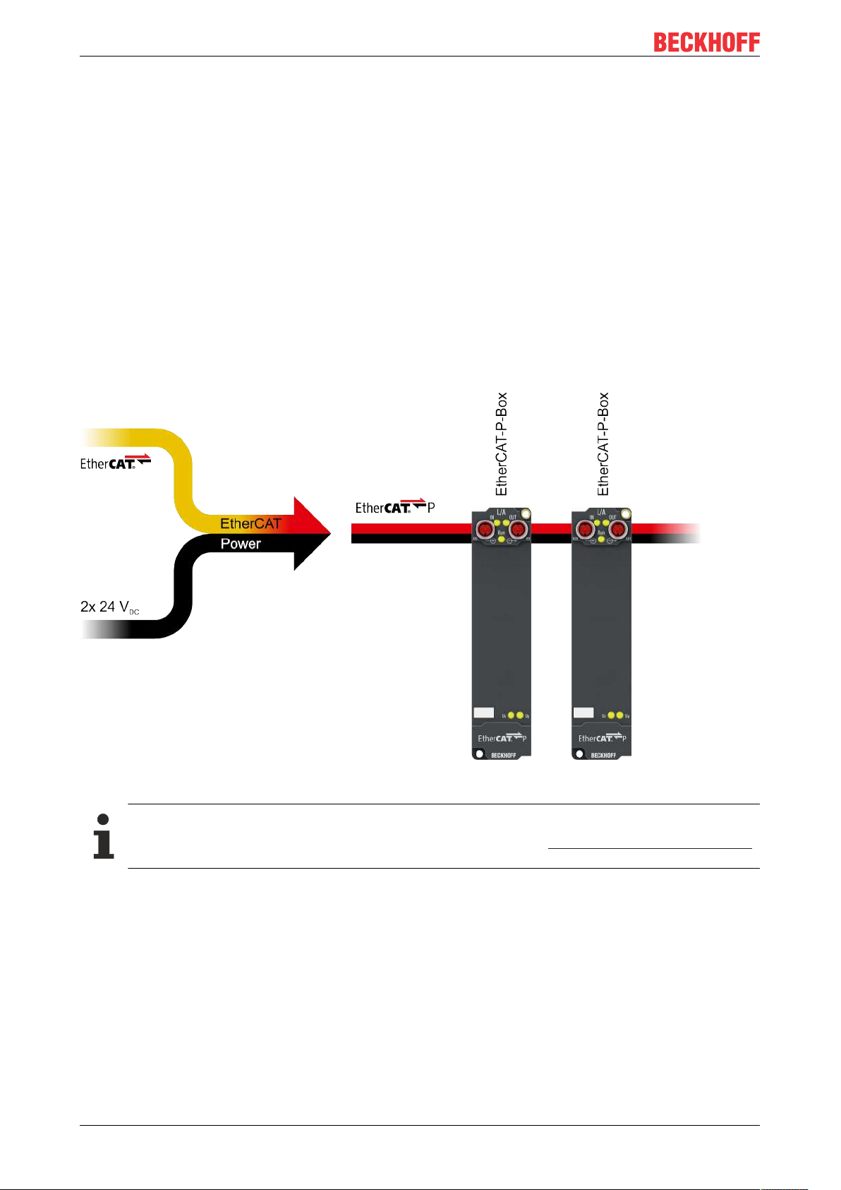
EtherCATP
EtherCATP supplements the EtherCAT technology with a process in which communication and supply
voltages are transmitted on a common line. All EtherCAT properties are retained with this process.
Two supply voltages are transmitted per EtherCATP line. The supply voltages are electrically isolated from
each other and can therefore be switched individually. The nominal supply voltage for both is 24 VDC.
EtherCAT P uses the same cable structure as EtherCAT: a 4-core Ethernet cable with M8 connectors. The
connectors are mechanically coded so that EtherCAT connectors and EtherCATP connectors cannot be
interchanged.
EtherCATP Box modules
EtherCATP Box modules are EtherCATP slaves with IP67 protection. They are designed for operation in
wet, dirty or dusty industrial environments.
Fig.1: EtherCATP
EtherCAT basics
A detailed description of the EtherCAT system can be found in the EtherCAT system documentation.
EPP3314-00028 Version: 1.2
Page 9
3 Product overview
3.1 Introduction
Product overview
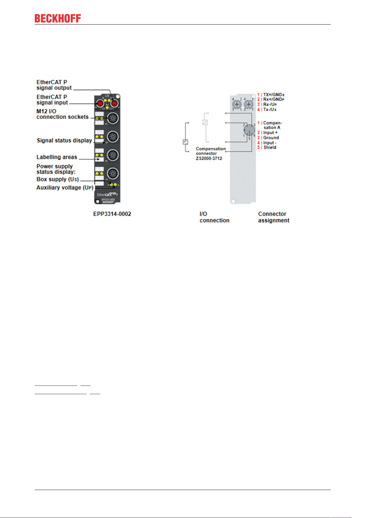
Fig.2: EPP3314-0002
4-channel analog input thermocouple
The EPP3314 EtherCAT P Box with analog inputs permits four thermocouples to be directly connected. The
module’s circuit can operate thermocouple sensors using the 2-wire technique. Linearisation over the full
temperature range is realised with the aid of a microprocessor. The temperature range can be selected
freely. The error LEDs indicate a broken wire. Compensation for the cold junction is made through a
temperature measurement in the connecting plugs. This means that standard extension leads can be
connected. The EPP3314 can also be used for mV measurement.
The module is quite versatile, but the default values are selected in such a way that in most cases it is not
necessary to perform configuration. The input filter and associated conversion times can be set within a wide
range; several data output formats may be chosen. If required, the inputs can be scaled differently.
Automatic limit monitoring is also available. Parameterisation is carried out via EtherCAT. The parameters
are stored in the module. For the temperature compensation a Pt1000 element is needed. Beckhoff offers a
connector with temperature compensation (ZS2000-3712).
Quick links
Technical data
Process image [}12]
Signal connection [}26]
EPP3314-0002 9Version: 1.2
Page 10

Product overview
3.2 Technical data
All values are typical values over the entire temperature range, unless stated otherwise.
EtherCATP
Connection 2xM8 socket, 4-pin, P-coded, red
Supply voltages
Connection See EtherCAT P connection
US nominal voltage 24VDC (-15%/ +20%)
US sum current: I
Current consumption from U
Rated voltage U
UP sum current: I
Current consumption from U
S,sum
S
P
P,sum
P
Thermocouple inputs
Number 4
Connector 4 x M12 socket
Cable length to thermocouple max. 30m
Sensor types
Electrical isolation The measuring channels have a common isolated ground
Measuring ranges
Measuring error Thermocouple type K: max. ±0.3%,
Digital resolution 16-bit
Value of an LSB Thermocouple: 0.1°C
Filter Digital filter. Filter frequency adjustable from 5Hz… 30kHz
Conversion time approx. 2.5 s to 20 ms, depending on configuration and filter
Diagnostics • Open-circuit recognition
max. 3A
100mA
24VDC (-15%/ +20%)
max. 3A
None. UP is only forwarded.
• Thermocouples [}11]
• Sensors with a voltage output of up to ±75mV
potential.
Thermocouples: depending on type [}11].
Voltage measurement: ±30mV, ±60mV, ±75mV
relative to the full scale value
Voltage measurement:
Measuring range 30mV: 1µV
Measuring range 60mV: 2µV
Measuring range 75mV: 4µV
setting.
Default: approx. 250ms
• Limit value monitoring
Housing data
Dimensions WxHxD 30mmx 126mmx 26.5mm (without connectors)
Weight approx. 165 g
Installation position variable
Material PA6 (polyamide)
EPP3314-000210 Version: 1.2
Page 11

Environmental conditions
Ambient temperature during operation -25…+60°C
-25…+55°C according to cULus
Ambient temperature during storage -40…+85°C
Vibration resistance, shock resistance conforms to EN 60068-2-6 / EN 60068-2-27
Additional checks [}11]
EMC immunity / emission conforms to EN 61000-6-2 / EN 61000-6-4
Protection class IP65, IP66, IP67 (conforms to EN 60529)
Approvals
Approvals
Additional checks
The boxes have been subjected to the following checks:
Verification Explanation
Vibration 10 frequency sweeps in 3 axes
5Hz<f<60Hz displacement 0.35mm, constant amplitude
60.1Hz<f<500Hz acceleration 5g, constant amplitude
Shocks 1000 shocks in each direction, in 3 axes
35g, 11ms
CE, cULus [}27]
Product overview
Overview of suitable thermocouples
The following thermocouples are suitable for temperature measurement:
Type (according
to EN60584-1)
B Pt30%Rh-Pt6Rh 600°C to 1800°C grey - grey - white
C * W5%Re-W25%Re 0°C to 2320°C n.d.
E NiCr-CuNi -100°C to 1000°C violet - violet - white
J Fe-CuNi -100°C to 1200°C black - black - white
K NiCr-Ni -200°C to 1370°C green - green - white
L ** Fe-CuNi 0°C to 900°C blue - red - blue
N NiCrSi-NiSi -100°C to 1300°C pink - pink - white
R Pt13%Rh-Pt 0°C to 1767°C orange - orange - white
S Pt10%Rh-Pt 0°C to 1760°C orange - orange - white
T Cu-CuNi -200°C to 400°C brown - brown - white
U ** Cu-CuNi 0°C to 600°C brown - red - brown
* not standardized according to EN60584-1
** according to DIN 43710
Element Implemented temperature
range
Color coding (sheath - plus
pole - minus pole)
EPP3314-0002 11Version: 1.2
Page 12
Product overview
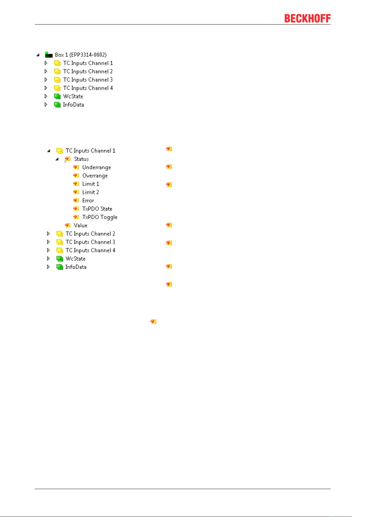
3.3 Process image
Fig.3: Process image
TC Inputs Channel1
• Underrange
Measurement is below range
• Overrange
Measuring range exceeded
• Limit 1
Status variable of the limit value monitoring
0: The limit value monitoring is disabled
1: The measured value is smaller than the limit value
2: The measured value is greater than the limit value
3: The measured value is exactly the same size as the limit value
• Limit 2
Status variable of the limit value monitoring
• Error
The current measured value "Value" is invalid.
Possible reasons: Wire breakage, Underrange, Overrange
• TxPDO State
If this bit is TRUE, the current measured value "Value" is invalid.
• TxPDO Toggle
The box inverts this bit every time it updates the measured value "Value" in
the process data.
This allows the currently required conversion time to be derived.
Value
The current measured value. Unit: 1/10°C.
TC Inputs Channel2 bis 4
The process data objects of channels 2…4 have exactly the same structure as those of channel 1.
EPP3314-000212 Version: 1.2
Page 13

3.4 Scope of supply
Make sure that the following components are included in the scope of delivery:
• 1x EPP3314-0002 EtherCAT P Box
• 2x protective cap for EtherCATP socket, M8, red (pre-assembled)
• 10x labels, blank (1 strip of 10)
Pre-assembled protective caps do not ensure IP67 protection
Protective caps are pre-assembled at the factory to protect connectors during transport. They may
not be tight enough to ensure IP67 protection.
Ensure that the protective caps are correctly seated to ensure IP67 protection.
Product overview
EPP3314-0002 13Version: 1.2
Page 14
Product overview
3.5 Basics of thermocouple technology
Thermocouples are temperature sensors. The application areas of thermocouples are very diverse due to
their low cost, fast detection of temperature differences, wide temperature ranges, high temperature limits
and availability in a wide range of types and sizes.
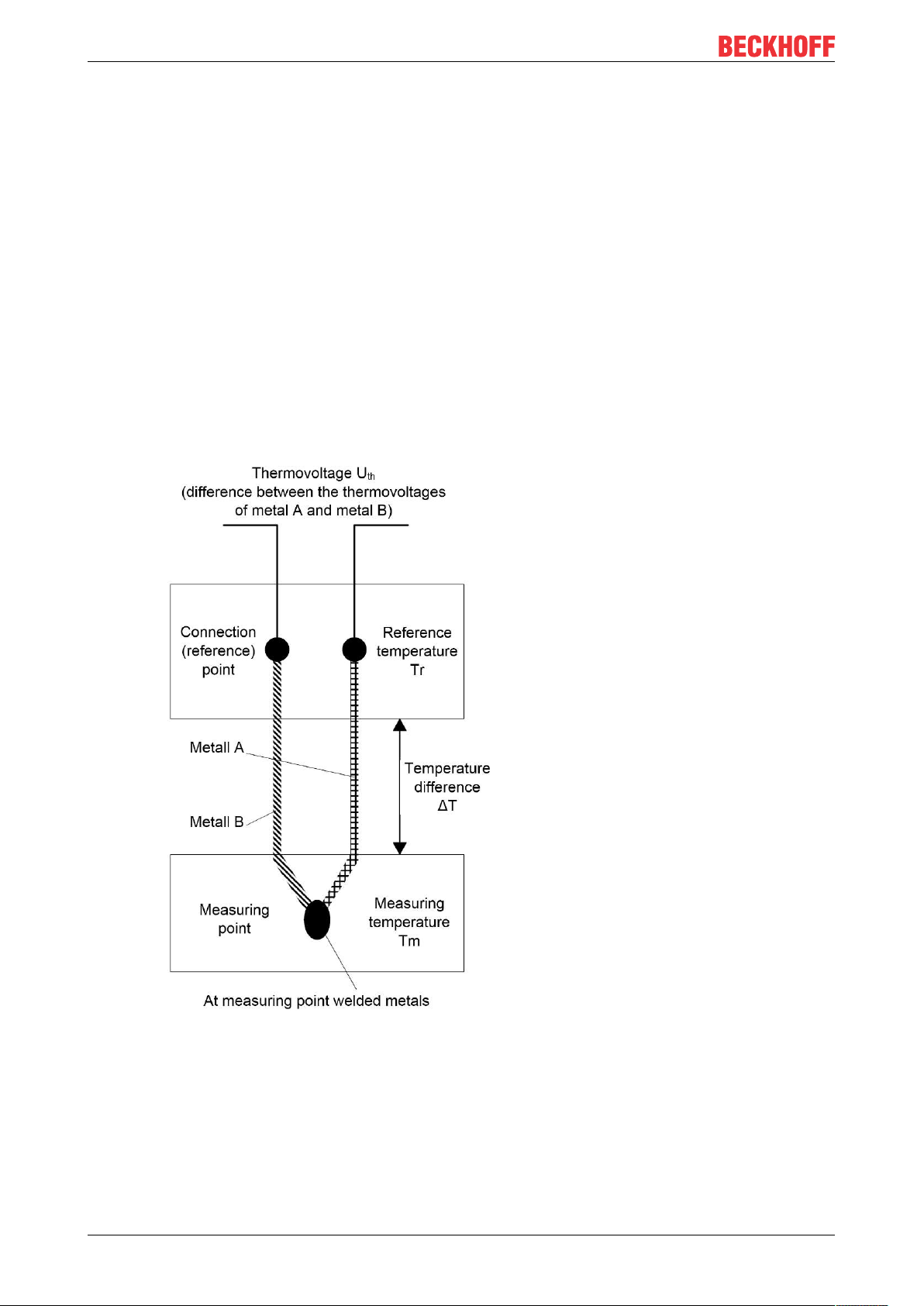
Measuring principle and configuration
Temperature measurement with a thermocouple is based on the Seebeck effect, which was discovered in
the 1820s by the German physicist Thomas Johann Seebeck. The Seebeck effect, also known as
thermoelectric effect, describes a charge shift in a conductive material due to a temperature gradient along
the conductor. The magnitude of the charge shift depends on the magnitude of the temperature difference
and the respective conductor material.
In thermocouples this charge shift is used to generate a voltage. Two different conductor materials are
connected at one end. This is the measuring point at which the temperature is to be determined. At the other
end the conductors are not connected. This open end, where the transition to the measuring electronics is
located, is the cold junction. A temperature difference occurs between the cold junction and the measuring
point, which can be measured via the voltage between the conductors at the open end. The voltage depends
on the conductor materials used and the temperature difference. It is in the range of a few mV.
Fig.4: Structure and principle of a thermocouple
If only one material were used for a thermocouple, the charge shift in both conductors would be identical, so
that no potential difference between the two conductors at the open end could be measured.
The temperature measurement with thermocouples is therefore actually a voltage measurement, based on
which a temperature can be determined from the known characteristic curve. In addition, the measuring
procedure is not absolute but differential, since no absolute temperature (with the reference point 0 °C) is
determined, but the temperature difference between the measuring point and the cold junction.
EPP3314-000214 Version: 1.2
Page 15

Product overview
For the evaluation of thermocouples, measuring electronics are required that can evaluate small voltages in
the mV range with sufficiently high resolution and accuracy. Thermocouples are active sensors, which
means that no sensor supply is required to measure the temperature.
Thermocouple types
There are different types of thermocouples, which consist of different combinations of conductor materials.
Each material combination has specific properties and is suitable for certain applications. The different
thermocouple types are distinguished by letters.
Due to the different material combinations, the different thermocouple types have different characteristic
values. They differ in the temperature limits and the characteristic voltage/temperature curve. In order to be
able to differentiate between the thermocouple types, the color codes for the sheath, the positive pole and
the negative pole are defined in various standards.
The following table shows common thermocouple types with the specification of the materials used, the
defined temperature ranges and the color coding.
Type (conforms to
EN60584-1)
B Pt30%Rh-Pt6Rh 600°C 1820°C 6µV/K 13.820mV grey - grey - white
C ** W5%Re-
E NiCr-CuNi -270°C 1000°C 65µV/K 76.373mV violet - violet - white
J Fe-CuNi -210°C 1200°C 54µV/K 69.553mV black - black - white
K NiCr-Ni -270°C 1372°C 42µV/K 54.886mV green - green - white
L *** Fe-CuNi -200°C 900°C 54µV/K 53.140mV blue - red - blue
N NiCrSi-NiSi -270°C 1300°C 27µV/K 47.513mV pink - pink - white
R Pt13%Rh-Pt -50°C 1768°C 10µV/K 21.101mV orange - orange - white
S Pt10%Rh-Pt -50°C 1768°C 10µV/K 18.693mV orange - orange - white
T Cu-CuNi -270°C 400°C 40µV/K 20.872mV brown - brown - white
U *** Cu-CuNi -200°C 600°C 40µV/K 34.310mV brown - red - brown
*The specified measuring range refers to the maximum possible measuring range of the specified
thermocouple type. The possible measuring range with the thermocouple module may be limited. The
specification of the possible measuring range of the thermocouple module can be taken from the technical
data in the documentation.
**not standardized according to EN60584-1
Element Measuring range * Average
min max
-18°C 2316°C 15µV/K 37.070mV n.d.
W25%Re
temperature
coefficient
Voltage at
FSV
Color coding (sheath plus pole - minus pole)
***conforms to DIN 43710
The thermocouple must be selected according to the operating conditions. Therefore, not only the
uncertainty must be taken into account, but also the other properties of the different thermocouple types. For
an application with small temperature fluctuations, it is advantageous to select a thermocouple type with a
high thermovoltage per temperature change. In an application where the temperature to be measured is very
high, it is important to observe the maximum operating temperature.
Characteristic curve
Type-specific reference tables are available for determining the temperature difference to a measured
thermovoltage. A simple conversion of the voltage into a temperature with a temperature coefficient, as is
often approximated in resistance thermometers, is not possible because the relationship between voltage
and temperature is clearly non-linear over the entire measuring range. The changing temperature coefficient
results in a non-linear characteristic voltage/temperature curve. This characteristic curve is in turn dependent
on the thermocouple type, so that each type has its own non-linear characteristic voltage/temperature curve.
As an example, the characteristic curves for typical thermocouple types are shown in the following diagram.
The non-linearity is particularly evident in the temperature range below 0°C.
EPP3314-0002 15Version: 1.2
Page 16
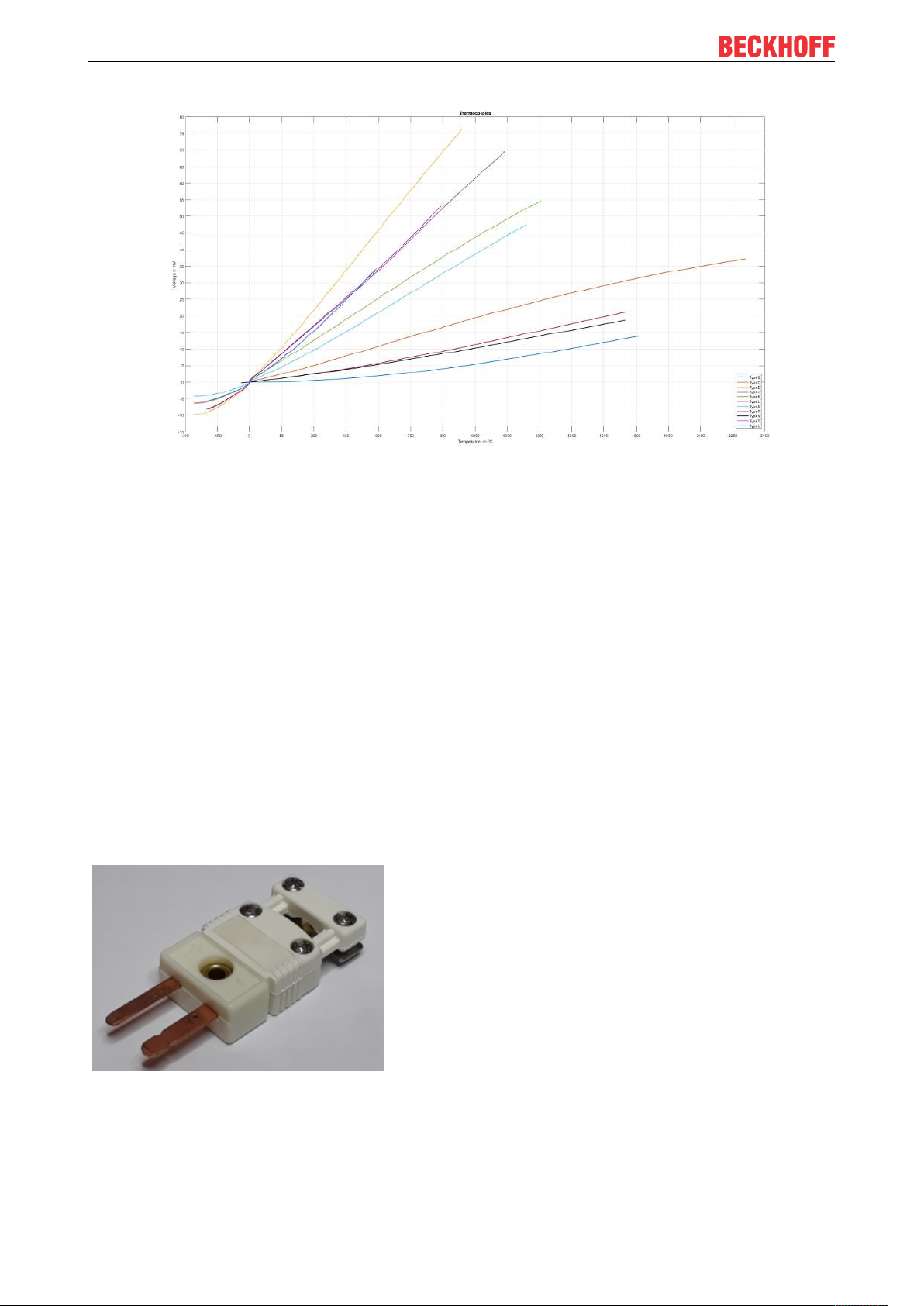
Product overview
Fig.5: Characteristic voltage/temperature curves of different thermocouple types
Thermocouples are subject to unavoidable and irreversible changes during practical application, which leads
to ever-increasing measurement uncertainties over time. In other words: the measurement becomes more
and more incorrect over time. These changes are also referred to as aging and depend on various
influencing factors. Examples of these influences are mechanical and chemical stresses on the
thermocouples. Mechanical stresses are deformations of the conductors, which change the crystal structure
of the metals. This leads to incorrect thermovoltages. Chemical stresses are also changes in the crystal
structure of the metals or oxidation, which change the thermal properties of the conductors, resulting in a
change in the characteristic curve. This influence can be reduced by installation in gas-tight protection tubes.
Pluggable connections
Open wire ends or suitable thermocouple connectors can be used to connect thermocouples to measuring
devices and evaluation electronics or to connect a thermocouple to thermo or compensating cables.
Ideally, the contacts of such a thermocouple connector are made of the material of the respective
thermocouple. This results in a thermovoltage-free transition at the connection points. The plugs are colorcoded depending on the type, e.g. type K is green. Labelling on the housing and different contact shapes are
intended to avoid polarity reversal.
There are several common sizes: standard, mini, micro.
A special feature is the white connector, which is designed with normal copper contacts, almost like a normal
non-thermocouple connector. This makes it universally applicable for all thermocouple types, although it has
the disadvantage that it does not create a thermovoltage-free transition. Far more common than the white
EPP3314-000216 Version: 1.2
Page 17

Product overview
plug is the white "universal" socket on the measuring device. This allows any thermocouple plug to be
plugged into the device. In the measuring device, the cold junction temperature must then be determined at
this plug transition.
Extensions and connection of thermocouples
In some cases it is useful to extend the thermocouple and thus to move the cold junction to a particular
location, where the temperature can be kept constant or measured by simple means. For this purpose the
thermocouple must be extended. This can be done with a thermo or compensation wire. Thermo cables are
made of the same material as the thermocouple itself. Compensating cables, on the other hand, are usually
made of cheaper materials with similar thermal properties. Both types are therefore suitable for extending a
thermocouple to a remote cold junction. The wires for thermo and compensating cables are standardized by
DIN 43713.
With compensating cables, care must be taken to ensure that the material used has similar thermal
properties but not identical properties. The thermal properties only apply in a narrowly limited temperature
range. At the transition from thermocouple to compensation wire, another thermocouple is created. This
results in small thermovoltage distortions, which influence the measurement result. If the compensating
cables are used outside the specified temperature range, the accuracy of the temperature measurement will
be further affected and the measurement result will deteriorate.
For both thermal and compensation wires, there are two accuracy classes that indicate the limit deviations.
These are defined in DIN43722. When selecting the thermocouple extension, the resulting uncertainty
should be considered and evaluated.
Sensor circuit
Changing the sensor circuit through additional elements such as selector switches or multiplexers
can affect the measuring accuracy. In such switches, small local thermovoltages can be generated
which distort the measurement. If such components cannot be avoided in the application, their influence should be carefully examined.
Maximum cable length to the thermocouple
Without additional protective measures, the maximum cable length from the measuring module (terminal, box) to the thermocouple is 30m. For longer cable lengths, suitable surge protection should
be provided.
Determination of the absolute temperature
Temperature measurement with a thermocouple is a differential temperature measurement, in which the
temperature difference between the measuring point and the reference junction, also known as cold junction,
is determined. To determine the absolute temperature at the measuring point, the measured thermovoltage
must therefore be corrected by the thermovoltage at the cold junction. With the corrected thermovoltage, the
temperature at the measuring point can then be determined from suitable tables or characteristic curves.
Due to the non-linearity of the characteristic curve, it is imperative that this calculation is carried out with the
voltages and not with the temperature. Otherwise, there would be a significant error in the measurement.
Difficulties in measuring temperature with thermocouples
- Linearization
- Cold junction compensation
In general, the absolute temperature is calculated using the following relationship:
U
measuring point
T
measuring point
= U
= f(U
+ U
thermo
measuring point
cold junction
)
In the following section, the absolute temperature is determined as an example based on correction of the
thermovoltages and the temperature. The example calculation can be used to illustrate the error resulting
from incorrect correction.
Sought: T
Known: Thermocouple type K, U
measuring point
= 24.255mV, T
thermo
cold junction
= 22°C
EPP3314-0002 17Version: 1.2
Page 18

Product overview
Option 1: Correction of thermovoltages – CORRECT
The thermovoltage at the cold junction U
from the characteristic voltage/temperature curve or table for thermocouple type K:
junction
U
cold junction
= U(22°C) = 0.879mV
cold junction
must be determined based on the known temperature T
The thermovoltage at the measuring point can then be determined with reference to 0°C:
U
measuring point
= U
thermo
+ U
cold junction
= 24.255mV + 0.879mV = 25.134mV
The corresponding temperature value can then be determined for thermocouple type K based on the
determined thermovoltage from the characteristic voltage/temperature curve or table:
T
measuring point
= T(25.134mV) ≈ 605.5°C
Option 2: Temperature correction – WRONG
In principle, the temperature difference between the cold junction and the measuring point T
determined based on the known thermovoltage U
from the characteristic voltage/temperature curve or
thermo
thermo
could be
table for thermocouple type K:
T
= T(24.255mV) = 585°C
thermo
The temperature of the measuring point could then be determined with reference to 0°C:
T
measuring point
= T
thermo
+ T
cold junction
= 585°C + 22°C = 607°C
Note that there is a temperature difference of 1.5°C between the value with the proper correction (voltage
correction, option 1) and the value with the incorrect correction (temperature correction, option 2).
cold
Reference junction / Cold junction compensation / CJC
The correction of the thermovoltage value to determine the absolute temperature value is referred to as cold
junction compensation. In order to determine an absolute temperature value that is as accurate as possible,
the temperature at the cold junction must either be kept constant at a known value or measured continuously
during the measurement with the smallest possible uncertainty. In some applications, the cold junction may
be in an ice bath (0°C), for example. In this case the temperature determined via the thermovoltage
corresponds to both the temperature difference and the absolute temperature. In many applications,
however, this option cannot be implemented, so that cold junction compensation is necessary.
As a cold junction in thermocouple evaluation with Bus Terminals, the cold junction temperature is measured
at the transition from the thermocouple to the copper contacts. This value is measured continuously during
operation in order to correct the determined values internally.
Evaluation of thermocouples with thermocouple terminals
Beckhoff thermocouple modules (terminals, box) can evaluate thermocouples of different types. Linearization
of the characteristic curves and determination of the reference temperature takes place directly in the
module. The module can be fully configured via the Bus Coupler or the controller. Different output formats
may be selected or own scaling activated. Linearization of the characteristic curve and determination and
calculation of the reference temperature (temperature at the connection contacts of the module) can be
deactivated, so the module can be used as a [mV] measuring device or with an external cold junction. In
addition to the internal evaluation of the measured voltage for conversion into a temperature, the raw voltage
value can be transferred from the terminal to the control system for further processing.
Temperature measurement with thermocouples generally comprises three steps:
• Measuring the electrical voltage
• Optional: Temperature measurement of the internal cold junction
• Software-based conversion of the voltage into a temperature value according to the set thermocouple
type (K, J, …)
All three steps can take place locally in the Beckhoff measuring module. Module-based transformation can
be disabled if the conversion is to take place in the higher-level control system. Depending on the module
type, several thermocouple conversions are available, which differ in terms of their software implementation.
EPP3314-000218 Version: 1.2
Page 19
Product overview
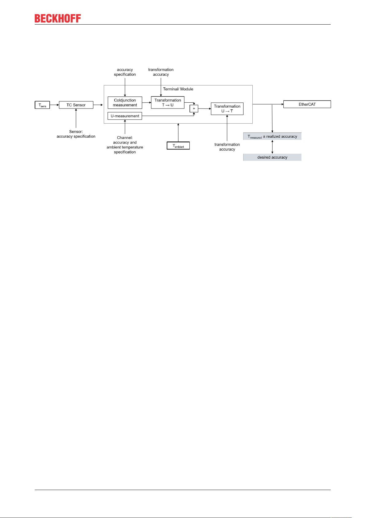
Uncertainties in the evaluation of thermocouples with thermocouple terminals
The thermocouple measurement consists of a chain of measuring and computing elements that affect the
attainable measurement deviation:
Fig.6: Concatenation of the uncertainties in temperature measurement with thermocouples
When measuring a temperature, there are various factors influencing the accuracy, from which the total
inaccuracy (total uncertainty) is then derived.
Uncertainty of the voltage measurement
First and foremost, measuring a temperature with thermocouples is not based on an actual temperature
measurement, but a voltage measurement with subsequent conversion into a temperature. The accuracy of
the voltage measurement is therefore the basis for the accuracy of the temperature determination. Since a
change of 1°C at the sensor causes a change in the single-digit µV range, depending on the thermocouple
type, even a small uncertainty of the voltage measurement has a large influence on the final result.
Uncertainty of the temperature conversion
The conversion of the measured voltage into a temperature is carried out during evaluation either by means
of value tables from the characteristic voltage/temperature curve of a thermocouple type or by approximation
based on a polynomial. Due to the non-linearity of the characteristic voltage/temperature curve, both options
are only approximations of the actual values, so that the conversion results in a further (small) transformation
uncertainty component.
Uncertainty of the cold junction evaluation
Cold junction compensation in thermocouple terminals must be carried out at the transition from the
thermocouple to the copper contacts of the electronics. However, in many cases the temperature at this
point cannot be measured directly for mechanical reasons. In this case the temperature of the cold junction
has to be approximated at a distance of a few millimeters or through an average value of the housing
temperatures. Since the exact value cannot be determined in this way, this results in further uncertainty.
Uncertainty of the sensor
The three factors influencing the uncertainty referred to above relate to the uncertainties in the evaluation of
the thermocouples. The accuracy of the thermocouple itself is another factor and must also be taken into
account.
Since temperature measurement with thermocouples is actually a voltage measurement and the
thermocouples have a non-linear characteristic voltage/temperature curve, it is not possible to simply add up
the individual temperature uncertainties to obtain the total uncertainty. To calculate the total uncertainty, all
temperature values must be converted into the corresponding voltage value of the respective thermocouple
type. When the temperatures are added together an error occurs, as described in the example in the chapter
on "Determination of the absolute temperature".
The following diagram shows an example of an analysis of the uncertainties associated with the evaluation
of a thermocouple for an EL331x thermocouple terminal with internal cold junction compensation and
conversion of the voltage into a temperature via a second degree polynomial. The diagram does not take
into account the uncertainty of the thermocouple itself, which is an additional factor.
EPP3314-0002 19Version: 1.2
Page 20
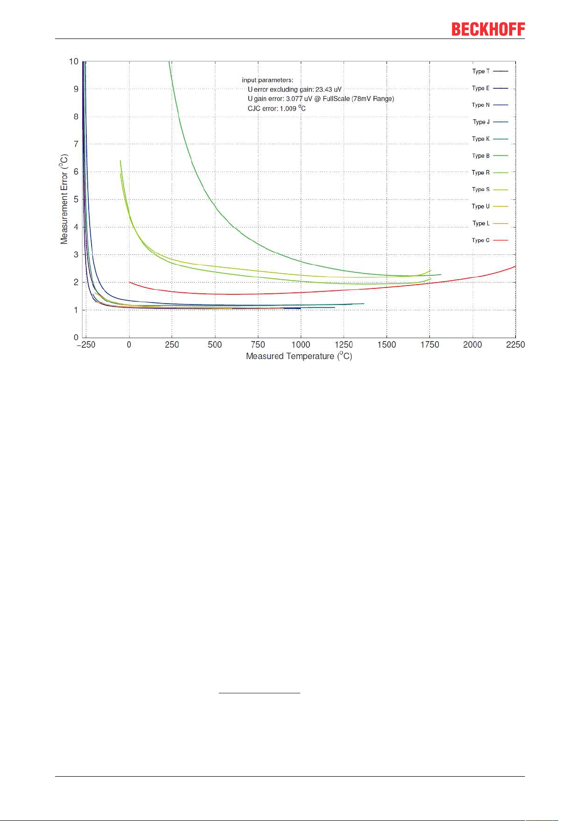
Product overview
Fig.7: Example for an uncertainty analysis of the evaluation of thermocouples with thermocouple terminals
It is clear from the diagram that the uncertainty of the measured temperature depends on the temperature to
be measured. Especially in the lower temperature range, where there is a strong non-linearity of voltage and
temperature, the uncertainty of the temperature measurement increases significantly.
Beckhoff offers several products for the evaluation of thermocouples, including
• EL331x-0000: EtherCAT terminal, 1/2/4/8 channel analog input, temperature, thermocouple, 16 bit
• EL3314-0002: EtherCAT terminal, 4 channel analog input, temperature, thermocouple, 24 bit,
electrically isolated
• EL3314-0010: EtherCAT terminal, 4 channel analog input, temperature, thermocouple, 24 bit, highprecision
• EL3314-0030: EtherCAT terminal, 4 channel analog input, temperature, thermocouple, 24 bit, highprecision, external calibrated
• EL3314-0090: EtherCAT terminal, 4 channel analog input, temperature, thermocouple, 16 bit,
TwinSAFE SC
• ELM370x-xxxx: EtherCAT terminal, 2/4 channel analog input, multi-functional, 24 bit, 10ksps
• ELM334x-xxxx: EtherCAT measurement technology series, thermocouple input, mini thermocouple
connector
• EP3314-0002: EtherCAT Box, 4 channel analog input, temperature, thermocouple, 16bit, M12
• EPP3314-0002: EtherCAT P Box, 4 channel analog input, temperature, thermocouple, 16bit, M12
• KL331x: bus terminal, 1/2/4 channel analog input, temperature, thermocouple, 16 bit
• EJ3318: EtherCAT plug-in module, 8 channel analog input, temperature, thermocouple, 16bit
The current overview can be found at www.beckhoff.com
EPP3314-000220 Version: 1.2
Page 21
4 Mounting and connections
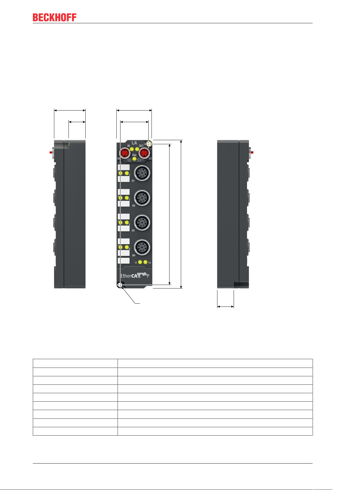
119
126
23
3026.5
14
Ø 3.5
13.5
4.1 Mounting
4.1.1 Dimensions
Mounting and connections
Fig.8: Dimensions
All dimensions are given in millimeters.
Housing features
Housing material PA6 (polyamide)
Sealing compound polyurethane
Mounting two fastening holes Ø 3.5 mm for M3
Metal parts brass, nickel-plated
Contacts CuZn, gold-plated
Installation position variable
Protection class IP65, IP66, IP67 (conforms to EN 60529) when screwed together
Dimensions (H x W x D) approx. 126 x 30 x 26.5 mm (without connectors)
Weight approx. 165g
EPP3314-0002 21Version: 1.2
Page 22

Mounting and connections
FE
4.1.2 Fixing
NOTE
Dirt during assembly
Dirty connectors can lead to malfunctions. Protection class IP67 can only be guaranteed if all cables and
connectors are connected.
• Protect the plug connectors against dirt during the assembly.
Mount the module with two M3 screws on the fastening holes in the corners of the module. The fastening
holes have no thread.
4.1.3 Functional earth (FE)
The upper fastening hole also serves as a connection for functional earth (FE).
Make sure that the box is grounded to low impedance via the functional earth (FE) connection. You can
achieve this, for example, by mounting the box on a grounded machine bed.
Fig.9: Connection for functional earth (FE)
4.1.4 Tightening torques for plug connectors
Screw connectors tight with a torque wrench. (e.g. ZB8801 from Beckhoff)
Connector diameter Tightening torque
M8 0.4Nm
M12 0.6Nm
EPP3314-000222 Version: 1.2
Page 23

Mounting and connections
1 2
1
2
3
4
4.2 Connections
4.2.1 EtherCATP
NOTE
Risk of damage to the device!
Bring the EtherCAT/EtherCATP system into a safe, powered down state before starting installation, disassembly or wiring of the modules!
NOTE
Pay attention to the maximum permissible current!
Pay attention also for the redirection of EtherCATP, the maximum permissible current for M8 connectors of
3A must not be exceeded!
4.2.1.1 Connectors
Fig.10: Plug connectors for EtherCAT P
1 - input
2 - downstream connection
Connection
Fig.11: M8 socket, P-coded
Contact Signal Voltage Core color
1 Tx + GND
2 Rx + GND
S
P
3 Rx - UP: Peripheral voltage, +24V
4 Tx - US: Control voltage, +24V
DC
DC
yellow
white
blue
orange
Housing Shield Shield Shield
1)
The core colors apply to EtherCAT P cables and ECP cables from Beckhoff.
1)
EPP3314-0002 23Version: 1.2
Page 24

Mounting and connections
4.2.1.2 Status LEDs
4.2.1.2.1 Supply voltages
Fig.12: Status LEDs for the supply voltages
EtherCAT P Box Modules have two LEDs that display the status of the supply voltages. The status LEDs are
labelled with the designations of the supply voltages: Us and Up.
A status LED lights up green when the respective supply voltage is present.
A Status LED lights up red if the respective supply voltage is short-circuited.
4.2.1.2.2 EtherCAT
Fig.13: Status LEDs for EtherCAT
L/A (Link/Act)
A green LED labelled "L/A" or “Link/Act” is located next to each EtherCAT/EtherCATP socket. The LED
indicates the communication state of the respective socket:
LED Meaning
off no connection to the connected EtherCAT device
lit LINK: connection to the connected EtherCAT device
flashes ACT: communication with the connected EtherCAT device
Run
Each EtherCAT slave has a green LED labelled "Run". The LED signals the status of the slave in the
EtherCAT network:
LED Meaning
off Slave is in "Init" state
flashes uniformly Slave is in "Pre-Operational“ state
flashes sporadically Slave is in "Safe-Operational" state
lit Slave is in "Operational" state
Description of the EtherCAT slave states
EPP3314-000224 Version: 1.2
Page 25

Mounting and connections
I = 3 A
10 20
5
10
15
20
300
0
25
40
Vert. Faktor: 0,22 cm / V
Voltage drop (V)
Cable length (m)
0.14 mm²
0.22 mm²
0.34 mm²
4.2.1.3 Conductor losses
Take into account the voltage drop on the supply line when planning a system. Avoid the voltage drop being
so high that the supply voltage at the box lies below the minimum nominal voltage.
Variations in the voltage of the power supply unit must also be taken into account.
Use the planning tool for EtherCAT P in TwinCAT.
Voltage drop on the supply line
Fig.14: Voltage drop on the supply line
EPP3314-0002 25Version: 1.2
Page 26

Mounting and connections
4.2.2 Thermocouples
The temperature compensation is fed to the outside of the modules. This means that in the connector the
temperature compensation is measured directly at the connection point. This allows the temperature to be
measured with significantly better accuracy. Beckhoff offer a connector (ZS2000-3712) for this. The
temperature compensation can also be carried out at a location other than the Fieldbus Box. You must then
wire a Pt1000 between pins 1 and 3. The longer the cables you choose to use, the larger is the
measurement error caused by the length of the conductor, conductor losses and interference.
4.2.2.1 Status LEDs at the signal connections
There is a green Run LED and a red Error LED for each channel.
Correct function is indicated if the green Run LED is on and the red Error is off.
Fig.15: Status LEDs at the signal connections
Connection LED Display Meaning
M12 socket no. 1-4 R
left
E
right
off No data transfer to the A/D converter
green Data transfer to A/D converter
off Function OK
red Error:
• Broken wire or
• measured value outside measuring range or
• temperature compensation outside the valid range
EPP3314-000226 Version: 1.2
Page 27

Mounting and connections
4.3 UL Requirements
The installation of the EtherCAT Box Modules certified by UL has to meet the following requirements.
Supply voltage
CAUTION
CAUTION!
This UL requirements are valid for all supply voltages of all marked EtherCAT Box Modules!
For the compliance of the UL requirements the EtherCAT Box Modules should only be supplied
• by a 24 VDC supply voltage, supplied by an isolating source and protected by means of a fuse (in accordance with UL248), rated maximum 4 Amp, or
• by a 24 VDC power source, that has to satisfy NEC class 2.
A NEC class 2 power supply shall not be connected in series or parallel with another (class 2) power
source!
CAUTION
CAUTION!
To meet the UL requirements, the EtherCAT Box Modules must not be connected to unlimited power
sources!
Networks
CAUTION
CAUTION!
To meet the UL requirements, EtherCAT Box Modules must not be connected to telecommunication networks!
Ambient temperature range
CAUTION
CAUTION!
To meet the UL requirements, EtherCAT Box Modules has to be operated only at an ambient temperature
range of 0 to 55°C!
Marking for UL
All EtherCAT Box Modules certified by UL (Underwriters Laboratories) are marked with the following label.
Fig.16: UL label
EPP3314-0002 27Version: 1.2
Page 28

Commissioning/Configuration
5 Commissioning/Configuration
5.1 Integration in TwinCAT
The procedure for integration in TwinCAT is described in this Quick start guide.
EPP3314-000228 Version: 1.2
Page 29

Commissioning/Configuration
5.2 Settings
5.2.1 Presentation, index 0x80n0:02
In the delivery state, the measured value is output in increments of 1/10° C in two's complement format
(signed integer).
Index 0x80n0:02 offers the possibility to change the method of representation of the measured value.
Measured value Output (hexadecimal) Output (signed integer, decimal)
-200.0 °C 0nF830 -2000
-100.0 °C 0nFC18 -1000
-0.1 °C 0nFFFF -1
0.0 °C 0n0000 0
0.1 °C 0n0001 1
100.0 °C 0n03E8 1000
200.0 °C 0n07D0 2000
500.0 °C 0x1388 5000
850.0 °C 0x2134 8500
1000.0 °C 0x2170 10000
Table 2: Output of measured value and process data
• Signed Integer:
The measured value is presented in two’s complement format.
Maximum presentation range for 16 bit = -32768 .. +32767
◦ Example:
◦ 1000 0000 0000 0000
◦ 1111 1111 1111 1110
◦ 1111 1111 1111 1111
◦ 0000 0000 0000 0001
◦ 0000 0000 0000 0010
◦ 0111 1111 1111 1111
= 0x8000
bin
= 0nFFFE
bin
= 0nFFFF
bin
= 0n0001
bin
= 0n0002
bin
= 0x7FFF
bin
= - 32768
hex
= - 2
hex
= - 1
hex
= +1
hex
= +2
hex
= +32767
hex
dec
dec
dec
dec
• Absolute value with MSB as sign:
The measured value is output in magnitude-sign format.
Maximum presentation range for 16 bit = -32767 .. +32767
◦ Example:
◦ 1111 1111 1111 1111
◦ 1000 0000 0000 0010
◦ 1000 0000 0000 0001
◦ 0000 0000 0000 0001
◦ 0000 0000 0000 0010
◦ 0111 1111 1111 1111
= 0nFFFF
bin
= 0x8002
bin
= 0x8001
bin
= 0n0001
bin
= 0n0002
bin
= 0x7FFF
bin
= - 32767
hex
= - 2
hex
= - 1
hex
= +1
hex
= +2
hex
= +32767
hex
dec
dec
dec
dec
• High resolution (1/100 C°):
The measured value is output in 1/100 °C steps.
dec
dec
dec
dec
EPP3314-0002 29Version: 1.2
Page 30

Commissioning/Configuration
5.2.2 Siemens bits, index 0x80n0:05
If the bit in index 0x80n0:05 is set, status displays are shown for the lowest 3 bits. In the error case
"overrange" or "underrange", bit 0 is set.
5.2.3 Underrange, Overrange
Undershoot and overshoot of the measuring range (underrange, overrange), index 0x60n0:02,
0x60n0:03
• Uk > Uk
of the characteristic curve is continued with the coefficients of the overrange limit up to the limit stop of
the A/D converter or to the maximum value of 0x7FFF.
• Uk < Uk
of the characteristic curve is continued with the coefficients of the underrange limit up to the limit stop
of the A/D converter or to the minimum value of 0x8000.
For overrange or underrange the red error LED is switched on.
: Index 0x60n0:02 and index 0x60n0:07 (overrange and error bit) are set. The linearization
max
: Index 0x60n0:01 and index 0x60n0:07 (underrange and error bit) are set. The linearization
max
5.2.4 Filter
Each analog input has a digital filter. The filter is a notch filter.
The filter is always active; it cannot be disabled. None of the "Enable Filter" parameters have any effect:
0x8000:06, 0x8010:06, 0x8020:06, 0x8030:06.
Configuring the filter
You can set the filter frequency in the parameter 0x8000:15 "Filter Settings". This parameter affects all
channels. The "Filter Settings" parameters of the other channels have no effect:
0x8010:15, 0x8020:15, 0x8030:15.
Influence on the conversion time
The higher the filter frequency, the shorter the conversion time.
5.2.5 Limit 1 and Limit 2
Limit 1 and limit 2, index 0x80n0:13, index 0x80n0:14
A temperature range can be set that is limited by the values in the indices 0x80n0:13 and 0x80n0:14. If the
limit values are overshot, the bits in indices 0x80n0:07 and 0x80n0:08 are set.
The temperature value is entered with a resolution of 0.1 °C.
Example:
Limit 1= 30 °C
Value index 0x80n0:13 = 300
EPP3314-000230 Version: 1.2
Page 31

Commissioning/Configuration
5.2.6 Calibration
Vendor calibration, index 0x80n0:0B
The vendor calibration is enabled via index 0x80n0:0B. Parameterization takes place via the indices
• 0x80nF:01
Thermocouple offset (vendor calibration)
• 0x80nF:02
Thermocouple gain (vendor calibration)
• 0x80nF:03
Reference point offset [Pt1000] (vendor calibration)
• 0x80nF:04
Reference point gain [Pt1000] (vendor calibration)
Vendor and user calibration
User calibration (index 0x80n0:0A) should only be performed instead of the vendor calibration (index 0x80n0:0B), but this is generally only necessary in exceptional cases.
User calibration , index 0x80n0:0A
User calibration is enabled via index 0x80n0:0A. Parameterization takes place via the indices
• 0x80n0:17
Thermocouple offset (index 0x80nF:01, user calibration)
• 0x80n0:18
Thermocouple gain (index 0x80nF:02, user calibration)
User scaling, index 0x80n0:01
The user scaling is enabled via index 0x80n0:01. Parameterization takes place via the indices
• 0x80n0:11
User scaling offset
The offset describes a vertical shift of the characteristic curve by a linear amount.
At a resolution of 0.1°, 1 digit
At a resolution of 0.01°, 1 digit
corresponds to an increase in measured value by 0.1°
(dec)
corresponds to an increase in measured value by 0.01
(dec)
• 0x80n0:12
User scaling gain
•
The default value of 65536
corresponds to gain = 1.
(dec)
The new gain value for 2-point user calibration after offset calibration is determined as follows:
Gain_new = reference temperature / measured value x 65536
(dec)
Calculation of process data
The concept "calibration", which has historical roots at Beckhoff, is used here even if it has nothing to do with
the deviation statements of a calibration certificate. Actually, this is a description of the vendor or customer
calibration data/adjustment data used by the device during operation in order to maintain the assured
measuring accuracy.
The box constantly records measured values and saves the raw values from its A/D converter in the ADC
raw value objects 0x80nE:01, 0x80nE:02. After each recording of the analog signal, the correction
calculation takes place with the vendor and user calibration data as well as the user scaling, if these are
activated (see following picture).
EPP3314-0002 31Version: 1.2
Page 32

Commissioning/Configuration
Fig.17: Calculation of process data
Calculation Designation
X
ADC
X
F
YH = (X
– BH) x AH x 2
ADC
YA = (YH – BA) x AA x 2
-14
-14
Output of the A/D converter
Output value after the filter
Measured value after vendor calibration,
Measured value after vendor and user calibration
YS= YA x AS x 2
-16
+ B
S
Measured value following user scaling
Table1: Legend
Name Designation Index
X
ADC
X
F
B
H
A
H
B
A
A
A
B
S
A
S
Y
S
Output value of the A/D converter 0x80nE:01
Output value after the filter Vendor calibration offset (not changeable) 0x80nF:01
Vendor calibration gain (not changeable) 0x80nF:02
User calibration offset (can be activated via index 0x80n0:0A) 0x80n0:17
User calibration gain (can be activated via index 0x80n0:0A) 0x80n0:18
User scaling offset (can be activated via index 0x80n0:01) 0x80n0:11
User scaling gain (can be activated via index 0x80n0:01) 0x80n0:12
Process data for controller -
Measurement result
The accuracy of the result may be reduced if the measured value is smaller than 32767 / 4 due to
one or more multiplications.
EPP3314-000232 Version: 1.2
Page 33

Commissioning/Configuration
5.3 Object overview
EtherCAT XML Device Description
The display matches that of the CoE objects from the EtherCAT XML Device Description. We recommend downloading the latest XML file from the download area of the Beckhoff website and installing it according to installation instructions.
Index (hex) Name Flags Default value
1000 [}45]
1008 [}45]
1009 [}45]
100A [}45]
1011:0 [}39]
1018:0 [}45]
10F0:0 [}45]
1600:0 [}45]
1601:0 [}46]
1602:0 [}46]
1603:0 [}46]
1A00:0 [}46]
1A01:0 [}47]
Subindex Restore default parameters RO 0x01 (1
1011:01 SubIndex 001 RW 0x00000000 (0
Subindex Identity RO 0x04 (4
1018:01 Vendor ID RO 0x00000002 (2
1018:02 Product code RO 0x64769529 (1685493033
1018:03 Revision RO 0x00120002 (1179650
1018:04 Serial number RO 0x00000000 (0
Subindex Backup parameter handling RO 0x01 (1
10F0:01 Checksum RO 0x00000000 (0
Subindex TC RxPDO-Map Outputs Ch.1 RO 0x01 (1
1600:01 SubIndex 001 RO 0x7000:11, 16
Subindex TC RxPDO-Map Outputs Ch.2 RO 0x01 (1
1601:01 SubIndex 001 RO 0x7010:11, 16
Subindex TC RxPDO-Map Outputs Ch.3 RO 0x01 (1
1602:01 SubIndex 001 RO 0x7020:11, 16
Subindex TC RxPDO-Map Outputs Ch.4 RO 0x01 (1
1603:01 SubIndex 001 RO 0x7030:11, 16
Subindex TC TxPDO-Map TCInputs Ch.1 RO 0x0A (10
1A00:01 SubIndex 001 RO 0x6000:01, 1
1A00:02 SubIndex 002 RO 0x6000:02, 1
1A00:03 SubIndex 003 RO 0x6000:03, 2
1A00:04 SubIndex 004 RO 0x6000:05, 2
1A00:05 SubIndex 005 RO 0x6000:07, 1
1A00:06 SubIndex 006 RO 0x0000:00, 1
1A00:07 SubIndex 007 RO 0x0000:00, 6
1A00:08 SubIndex 008 RO 0x6000:0F, 1
1A00:09 SubIndex 009 RO 0x6000:10, 1
1A00:0A SubIndex 010 RO 0x6000:11, 16
Subindex TC TxPDO-Map TCInputs Ch.2 RO 0x0A (10
1A01:01 SubIndex 001 RO 0x6010:01, 1
1A01:02 SubIndex 002 RO 0x6010:02, 1
1A01:03 SubIndex 003 RO 0x6010:03, 2
1A01:04 SubIndex 004 RO 0x6010:05, 2
1A01:05 SubIndex 005 RO 0x6010:07, 1
1A01:06 SubIndex 006 RO 0x0000:00, 1
1A01:07 SubIndex 007 RO 0x0000:00, 6
1A01:08 SubIndex 008 RO 0x6010:0F, 1
1A01:09 SubIndex 009 RO 0x6010:10, 1
1A01:0A SubIndex 010 RO 0x6010:11, 16
Device type RO 0x014A1389 (21631881
Device name RO EPP3314-0002
Hardware version RO 04
Software version RO 06
)
dec
)
dec
)
dec
)
dec
)
dec
)
dec
)
dec
dec
dec
)
dec
)
dec
)
dec
)
dec
)
dec
)
dec
)
dec
)
)
EPP3314-0002 33Version: 1.2
Page 34

Commissioning/Configuration
Index (hex) Name Flags Default value
1A02:0 [}47]
1A03:0 [}48]
1C00:0 [}48]
1C12:0 [}48]
1C13:0 [}48]
1C32:0 [}49]
1C33:0 [}50]
Subindex TC TxPDO-Map TCInputs Ch.3 RO 0x0A (10
dec
1A02:01 SubIndex 001 RO 0x6020:01, 1
1A02:02 SubIndex 002 RO 0x6020:02, 1
1A02:03 SubIndex 003 RO 0x6020:03, 2
1A02:04 SubIndex 004 RO 0x6020:05, 2
1A02:05 SubIndex 005 RO 0x6020:07, 1
1A02:06 SubIndex 006 RO 0x0000:00, 1
1A02:07 SubIndex 007 RO 0x0000:00, 6
1A02:08 SubIndex 008 RO 0x6020:0F, 1
1A02:09 SubIndex 009 RO 0x6020:10, 1
1A02:0A SubIndex 010 RO 0x6020:11, 16
Subindex TC TxPDO-Map TCInputs Ch.4 RO 0x0A (10
dec
1A03:01 SubIndex 001 RO 0x6030:01, 1
1A03:02 SubIndex 002 RO 0x6030:02, 1
1A03:03 SubIndex 003 RO 0x6030:03, 2
1A03:04 SubIndex 004 RO 0x6030:05, 2
1A03:05 SubIndex 005 RO 0x6030:07, 1
1A03:06 SubIndex 006 RO 0x0000:00, 1
1A03:07 SubIndex 007 RO 0x0000:00, 6
1A03:08 SubIndex 008 RO 0x6030:0F, 1
1A03:09 SubIndex 009 RO 0x6030:10, 1
1A03:0A SubIndex 010 RO 0x6030:11, 16
Subindex Sync manager type RO 0x04 (4
1C00:01 SubIndex 001 RO 0x01 (1
1C00:02 SubIndex 002 RO 0x02 (2
1C00:03 SubIndex 003 RO 0x03 (3
1C00:04 SubIndex 004 RO 0x04 (4
Subindex RxPDO assign RW 0x00 (0
1C12:01 SubIndex 001 RW 0x0000 (0
1C12:02 SubIndex 002 RW 0x0000 (0
1C12:03 SubIndex 003 RW 0x0000 (0
1C12:04 SubIndex 004 RW 0x0000 (0
Subindex TxPDO assign RW 0x04 (4
)
dec
)
dec
)
dec
)
dec
)
dec
)
dec
dec
dec
dec
dec
)
dec
1C13:01 SubIndex 001 RW 0x1A00 (6656
1C13:02 SubIndex 002 RW 0x1A01 (6657
1C13:03 SubIndex 003 RW 0x1A02 (6658
1C13:04 SubIndex 004 RW 0x1A03 (6659
Subindex SM output parameter RO 0x20 (32
1C32:01 Sync mode RW 0x0000 (0
)
dec
dec
1C32:02 Cycle time RW 0x000F4240 (1000000
1C32:03 Shift time RO 0x00000000 (0
1C32:04 Sync modes supported RO 0xC007 (49159
1C32:05 Minimum cycle time RO 0x00002710 (10000
1C32:06 Calc and copy time RO 0x00000000 (0
1C32:07 Minimum delay time RO 0x00000000 (0
1C32:08 Command RW 0x0000 (0
dec
1C32:09 Maximum Delay time RO 0x00000000 (0
1C32:0B SM event missed counter RO 0x0000 (0
1C32:0C Cycle exceeded counter RO 0x0000 (0
1C32:0D Shift too short counter RO 0x0000 (0
1C32:20 Sync error RO 0x00 (0
Subindex SM input parameter RO 0x20 (32
1C33:01 Sync mode RW 0x0000 (0
dec
dec
dec
)
dec
)
dec
dec
1C33:02 Cycle time RW 0x000F4240 (1000000
1C33:03 Shift time RO 0x00000000 (0
1C33:04 Sync modes supported RO 0xC007 (49159
1C33:05 Minimum cycle time RO 0x00002710 (10000
1C33:06 Calc and copy time RO 0x00000000 (0
)
)
)
)
)
)
)
dec
)
dec
)
dec
)
dec
)
)
dec
)
dec
)
dec
)
dec
)
dec
)
dec
)
)
dec
)
)
)
)
)
dec
)
dec
)
dec
)
dec
)
dec
EPP3314-000234 Version: 1.2
Page 35

Commissioning/Configuration
Index (hex) Name Flags Default value
1C33:07 Minimum delay time RO 0x00000000 (0
6000:0 [}51]
6010:0 [}51]
6020:0 [}52]
6030:0 [}52]
7000:0 [}53]
7010:0 [}53]t
7020:0 [}53]
7030:0 [}53]
8000:0 [}40]
1C33:08 Command RW 0x0000 (0
1C33:09 Maximum Delay time RO 0x00000000 (0
1C33:0B SM event missed counter RO 0x0000 (0
1C33:0C Cycle exceeded counter RO 0x0000 (0
1C33:0D Shift too short counter RO 0x0000 (0
1C33:20 Sync error RO 0x00 (0
Subindex TC Inputs Ch.1 RO 0x11 (17
6000:01 Underrange RO 0x00 (0
6000:02 Overrange RO 0x00 (0
6000:03 Limit 1 RO 0x00 (0
6000:05 Limit 2 RO 0x00 (0
6000:07 Error RO 0x00 (0
6000:0E Sync error RO 0x00 (0
6000:0F TxPDO State RO 0x00 (0
6000:10 TxPDO Toggle RO 0x00 (0
6000:11 Value RO 0x0000 (0
Subindex TC Inputs Ch.2 RO 0x11 (17
6010:01 Underrange RO 0x00 (0
6010:02 Overrange RO 0x00 (0
6010:03 Limit 1 RO 0x00 (0
6010:05 Limit 2 RO 0x00 (0
6010:07 Error RO 0x00 (0
6010:0E Sync error RO 0x00 (0
6010:0F TxPDO State RO 0x00 (0
6010:10 TxPDO Toggle RO 0x00 (0
6010:11 Value RO 0x0000 (0
Subindex TC Inputs Ch.3 RO 0x11 (17
6020:01 Underrange RO 0x00 (0
6020:02 Overrange RO 0x00 (0
6020:03 Limit 1 RO 0x00 (0
6020:05 Limit 2 RO 0x00 (0
6020:07 Error RO 0x00 (0
6020:0E Sync error RO 0x00 (0
6020:0F TxPDO State RO 0x00 (0
6020:10 TxPDO Toggle RO 0x00 (0
6020:11 Value RO 0x0000 (0
Subindex TC Inputs Ch.4 RO 0x11 (17
6030:01 Underrange RO 0x00 (0
6030:02 Overrange RO 0x00 (0
6030:03 Limit 1 RO 0x00 (0
6030:05 Limit 2 RO 0x00 (0
6030:07 Error RO 0x00 (0
6030:0E Sync error RO 0x00 (0
6030:0F TxPDO State RO 0x00 (0
6030:10 TxPDO Toggle RO 0x00 (0
6030:11 Value RO 0x0000 (0
Subindex TC Outputs Ch.1 RO 0x11 (17
7000:11 CJCompensation RO 0x0000 (0
Subindex TC Outputs Ch.2 RO 0x11 (17
7010:11 CJCompensation RO 0x0000 (0
Subindex TC Outputs Ch.3 RO 0x11 (17
7020:11 CJCompensation RO 0x0000 (0
Subindex TC Outputs Ch.4 RO 0x11 (17
7030:11 CJCompensation RO 0x0000 (0
Subindex TC Settings Ch.1 RW 0x1B (27
8000:01 Enable user scale RW 0x00 (0
8000:02 Presentation RW 0x00 (0
dec
dec
dec
dec
)
dec
)
dec
)
dec
)
dec
)
dec
)
dec
)
dec
)
dec
)
dec
)
dec
dec
)
dec
)
dec
)
dec
)
dec
)
dec
)
dec
)
dec
)
dec
)
dec
dec
)
dec
)
dec
)
dec
)
dec
)
dec
)
dec
)
dec
)
dec
)
dec
dec
)
dec
)
dec
)
dec
)
dec
)
dec
)
dec
)
dec
)
dec
)
dec
dec
)
dec
dec
)
dec
dec
)
dec
dec
)
dec
dec
)
dec
)
dec
)
dec
)
dec
)
)
dec
)
)
)
)
)
)
)
)
)
)
)
EPP3314-0002 35Version: 1.2
Page 36

Commissioning/Configuration
Index (hex) Name Flags Default value
800E:0 [}53]
800F:0 [}53]
8010:0 [}41]
801E:0 [}54]
801F:0 [}54]
8000:05 Siemens bits RW 0x00 (0
8000:06 Enable filter RW 0x00 (0
8000:07 Enable limit 1 RW 0x00 (0
8000:08 Enable limit 2 RW 0x00 (0
8000:0A Enable user calibration RW 0x00 (0
8000:0B Enable vendor calibration RW 0x01 (1
8000:0C Coldjunction compensation RW 0x00 (0
8000:0E Swap limit bits RW 0x00 (0
8000:11 User scale offset RW 0x0000 (0
8000:12 User scale gain RW 0x00010000 (65536
8000:13 Limit 1 RW 0x0000 (0
8000:14 Limit 2 RW 0x0000 (0
8000:15 Filter settings RW 0x0000 (0
8000:16 Calibration intervall RW 0x0000 (0
8000:17 User calibration offset RW 0x0000 (0
8000:18 User calibration gain RW 0x4000 (16384
8000:19 Sensor Type RW 0x0000 (0
8000:1B Wire calibration 1/32 Ohm RW 0x0000 (0
Subindex TC Internal data Ch.1 RO 0x05 (5
800E:01 ADC raw value TC RO 0x00000000 (0
800E:02 ADC raw value PT1000 RO 0x00000000 (0
800E:03 CJ temperature RO 0x0000 (0
800E:04 CJ voltage RO 0x0000 (0
800E:05 CJ resistor RO 0x0000 (0
Subindex TC Vendor data Ch.1 RW 0x04 (4
800F:01 Calibration offset TC RW 0x0000 (0
800F:02 Calibration gain TC RW 0x4000 (16384
800F:03 Calibration offset CJ RW 0x0000 (0
800F:04 Calibration gain CJ RW 0x4000 (16384
Subindex TC Settings Ch.2 RW 0x1B (27
8010:01 Enable user scale RW 0x00 (0
8010:02 Presentation RW 0x00 (0
8010:05 Siemens bits RW 0x00 (0
8010:06 Enable filter RW 0x00 (0
8010:07 Enable limit 1 RW 0x00 (0
8010:08 Enable limit 2 RW 0x00 (0
8010:0A Enable user calibration RW 0x00 (0
8010:0B Enable vendor calibration RW 0x01 (1
8010:0C Coldjunction compensation RW 0x00 (0
8010:0E Swap limit bits RW 0x00 (0
8010:11 User scale offset RW 0x0000 (0
8010:12 User scale gain RW 0x00010000 (65536
8010:13 Limit 1 RW 0x0000 (0
8010:14 Limit 2 RW 0x0000 (0
8010:15 Filter settings RW 0x0000 (0
8010:16 Calibration intervall RW 0x0000 (0
8010:17 User calibration offset RW 0x0000 (0
8010:18 User calibration gain RW 0x4000 (16384
8010:19 Sensor Type RW 0x0000 (0
8010:1B Wire calibration 1/32 Ohm RW 0x0000 (0
Subindex TC Internal data Ch.2 RO 0x05 (5
801E:01 ADC raw value TC RO 0x00000000 (0
801E:02 ADC raw value PT1000 RO 0x00000000 (0
801E:03 CJ temperature RO 0x0000 (0
801E:04 CJ voltage RO 0x0000 (0
801E:05 CJ resistor RO 0x0000 (0
Subindex TC Vendor data Ch.2 RW 0x04 (4
801F:01 Calibration offset TC RW 0x0000 (0
)
dec
)
dec
)
dec
)
dec
)
dec
)
dec
)
dec
)
dec
dec
dec
dec
dec
dec
dec
dec
dec
)
dec
dec
dec
dec
)
dec
dec
dec
dec
)
dec
)
dec
)
dec
)
dec
)
dec
)
dec
)
dec
)
dec
)
dec
)
dec
dec
dec
dec
dec
dec
dec
dec
dec
)
dec
dec
dec
dec
)
dec
dec
)
)
dec
)
)
)
)
)
)
dec
)
)
)
dec
)
dec
)
)
)
)
)
dec
)
)
dec
)
)
)
dec
)
)
)
)
)
)
dec
)
)
)
dec
)
dec
)
)
)
)
EPP3314-000236 Version: 1.2
Page 37

Commissioning/Configuration
Index (hex) Name Flags Default value
801F:02 Calibration gain TC RW 0x4000 (16384
8020:0 [}42]
802E:0 [}54]
802F:0 [}54]
8030:0 [}44]
803E:0 [}54]
801F:03 Calibration offset CJ RW 0x0000 (0
801F:04 Calibration gain CJ RW 0x4000 (16384
Subindex TC Settings Ch.3 RW 0x1B (27
8020:01 Enable user scale RW 0x00 (0
8020:02 Presentation RW 0x00 (0
8020:05 Siemens bits RW 0x00 (0
8020:06 Enable filter RW 0x00 (0
8020:07 Enable limit 1 RW 0x00 (0
8020:08 Enable limit 2 RW 0x00 (0
8020:0A Enable user calibration RW 0x00 (0
8020:0B Enable vendor calibration RW 0x01 (1
8020:0C Coldjunction compensation RW 0x00 (0
8020:0E Swap limit bits RW 0x00 (0
8020:11 User scale offset RW 0x0000 (0
8020:12 User scale gain RW 0x00010000 (65536
8020:13 Limit 1 RW 0x0000 (0
8020:14 Limit 2 RW 0x0000 (0
8020:15 Filter settings RW 0x0000 (0
8020:16 Calibration intervall RW 0x0000 (0
8020:17 User calibration offset RW 0x0000 (0
8020:18 User calibration gain RW 0x4000 (16384
8020:19 Sensor Type RW 0x0000 (0
8020:1B Wire calibration 1/32 Ohm RW 0x0000 (0
Subindex TC Internal data Ch.3 RO 0x05 (5
802E:01 ADC raw value TC RO 0x00000000 (0
802E:02 ADC raw value PT1000 RO 0x00000000 (0
802E:03 CJ temperature RO 0x0000 (0
802E:04 CJ voltage RO 0x0000 (0
802E:05 CJ resistor RO 0x0000 (0
Subindex TC Vendor data Ch.3 RW 0x04 (4
802F:01 Calibration offset TC RW 0x0000 (0
802F:02 Calibration gain TC RW 0x4000 (16384
802F:03 Calibration offset CJ RW 0x0000 (0
802F:04 Calibration gain CJ RW 0x4000 (16384
Subindex TC Settings Ch.4 RW 0x1B (27
8030:01 Enable user scale RW 0x00 (0
8030:02 Presentation RW 0x00 (0
8030:05 Siemens bits RW 0x00 (0
8030:06 Enable filter RW 0x00 (0
8030:07 Enable limit 1 RW 0x00 (0
8030:08 Enable limit 2 RW 0x00 (0
8030:0A Enable user calibration RW 0x00 (0
8030:0B Enable vendor calibration RW 0x01 (1
8030:0C Coldjunction compensation RW 0x00 (0
8030:0E Swap limit bits RW 0x00 (0
8030:11 User scale offset RW 0x0000 (0
8030:12 User scale gain RW 0x00010000 (65536
8030:13 Limit 1 RW 0x0000 (0
8030:14 Limit 2 RW 0x0000 (0
8030:15 Filter settings RW 0x0000 (0
8030:16 Calibration intervall RW 0x0000 (0
8030:17 User calibration offset RW 0x0000 (0
8030:18 User calibration gain RW 0x4000 (16384
8030:19 Sensor Type RW 0x0000 (0
8030:1B Wire calibration 1/32 Ohm RW 0x0000 (0
Subindex TC Internal data Ch.4 RO 0x05 (5
803E:01 ADC raw value TC RO 0x00000000 (0
dec
)
dec
)
dec
)
dec
)
dec
)
dec
)
dec
)
dec
)
dec
)
dec
)
dec
)
dec
dec
dec
dec
dec
dec
dec
dec
dec
)
dec
dec
dec
dec
)
dec
dec
dec
)
dec
)
dec
)
dec
)
dec
)
dec
)
dec
)
dec
)
dec
)
dec
)
dec
)
dec
dec
dec
dec
dec
dec
dec
dec
dec
)
dec
)
dec
)
)
dec
)
)
dec
)
)
)
)
)
)
dec
)
)
)
dec
)
dec
)
)
)
)
)
dec
)
)
dec
)
)
dec
)
)
)
)
)
)
dec
)
)
)
dec
EPP3314-0002 37Version: 1.2
Page 38

Commissioning/Configuration
Index (hex) Name Flags Default value
803E:02 ADC raw value PT1000 RO 0x00000000 (0
803F:0 [}55]
F000:0 [}55]
F008 [}55]
F010:0 [}55]
F080:0 [}55]
803E:03 CJ temperature RO 0x0000 (0
803E:04 CJ voltage RO 0x0000 (0
803E:05 CJ resistor RO 0x0000 (0
Subindex TC Vendor data Ch.4 RW 0x04 (4
803F:01 Calibration offset TC RW 0x0000 (0
803F:02 Calibration gain TC RW 0x4000 (16384
803F:03 Calibration offset CJ RW 0x0000 (0
803F:04 Calibration gain CJ RW 0x4000 (16384
Subindex Modular device profile RO 0x02 (2
F000:01 Module index distance RO 0x0010 (16
F000:02 Maximum number of modules RO 0x0004 (4
Code word RW 0x00000000 (0
Subindex Module list RW 0x04 (4
F010:01 SubIndex 001 RW 0x0000014A (330
F010:02 SubIndex 002 RW 0x0000014A (330
F010:03 SubIndex 003 RW 0x0000014A (330
F010:04 SubIndex 004 RW 0x0000014A (330
Subindex Channel Enable RO 0x04 (4
F080:01 SubIndex 001 RW 0xFF (255
F080:02 SubIndex 002 RW 0xFF (255
F080:03 SubIndex 003 RW 0xFF (255
F080:04 SubIndex 004 RW 0xFF (255
dec
dec
dec
)
dec
dec
dec
)
dec
dec
)
dec
)
dec
dec
dec
dec
dec
)
dec
)
)
)
)
)
dec
)
)
dec
)
dec
)
)
dec
)
dec
)
dec
)
dec
)
dec
)
)
)
)
Key
Flags:
RO (Read Only): this object can be read only
RW (Read/Write): this object can be read and written to
EPP3314-000238 Version: 1.2
Page 39

Commissioning/Configuration
5.4 Object description and parameterization
EtherCAT XML Device Description
The display matches that of the CoE objects from the EtherCAT XML Device Description. We recommend downloading the latest XML file from the download area of the Beckhoff website and installing it according to installation instructions.
Parameterization via the CoE list (CAN over EtherCAT)
The EtherCAT device is parameterized via the CoE - Online tab (double-click on the respective object) or via the Process Data tab (allocation of PDOs).
Introduction
The CoE overview contains objects for different intended applications:
• Objects required for parameterization during commissioning
• Objects intended for regular operation [}45], e.g. through ADS access
• Objects for indicating internal settings [}39] (may be fixed)
• Further profile-specific objects [}51] indicating inputs, outputs and status information
The following section first describes the objects required for normal operation, followed by a complete
overview of missing objects.
5.4.1 Objects to be parameterized during commissioning
Index 1011: Restore default parameters
Index (hex) Name Meaning Data type Flags Default
1011:0 Restore default pa-
rameters
1011:01 SubIndex 001 If this object is set to "0x64616F6C" in the set value dia-
Restore default parameters UINT8 RO 0x01 (1
log, all backup objects are reset to their delivery state.
UINT32 RW 0x00000000
(0
)
dec
)
dec
EPP3314-0002 39Version: 1.2
Page 40

Commissioning/Configuration
Index 8000: TC Settings Ch.1
Index (hex) Name Meaning Data type Flags Default
8000:0 TC Settings Ch.1 Maximum subindex UINT8 RO 0x1B (27
8000:01 Enable user scale Activates user scaling BOOLEAN RW 0x00 (0
8000:02 Presentation Presentation of the measured value BIT3 RW 0x00 (0
0 Signed, in two's complement
1 Most significant bit as sign
2 High-resolution (1/100 °C steps)
8000:05 Siemens bits The S5 bits are displayed in the three low-order bits BOOLEAN RW 0x00 (0
8000:06 Enable filter This parameter is without effect. The filter is always en-
BOOLEAN RW 0x00 (0
abled.
8000:07 Enable limit 1 Activates limit check for limit 1 BOOLEAN RW 0x00 (0
8000:08 Enable limit 2 Activates limit check for limit 2 BOOLEAN RW 0x00 (0
8000:0A Enable user calibra-
Activates user calibration BOOLEAN RW 0x00 (0
tion
8000:0B Enable vendor cali-
Activates vendor calibration BOOLEAN RW 0x01 (1
bration
8000:0C Cold junction com-
pensation
Cold junction compensation BIT2 RW 0x00 (0
0 Cold junction compensation takes place via the
Pt1000 in the plug connector.
1 Cold junction compensation is not active.
2 Cold junction compensation takes place via the
process data.
3 Same as value 0.
8000:0E Swap limit bits Swaps the two limit bits, in order to achieve compatibility
BOOLEAN RW 0x00 (0
with older hardware versions.
8000:11 User scale offset User scaling: Offset INT16 RW 0x0000 (0
8000:12 User scale gain User scaling: Gain INT32 RW 0x00010000
(65536
8000:13 Limit 1 Value for limit 1 INT16 RW 0x0000 (0
8000:14 Limit 2 Value for limit 2 INT16 RW 0x0000 (0
8000:15 Filter settings Filter settings (Ch1. applies to all channels) UINT16 RW 0x0000 (0
0 50Hz
1 60Hz
2 100Hz
3 500Hz
4 1kHz,
5 2kHz
6 3.75kHz
7 7.5kHz
8 15kHz
9 30kHz
10 5Hz
11 10Hz
8000:16 Calibration interval reserved UINT16 RW 0x0000 (0
8000:17 User calibration offset User calibration: Offset INT16 RW 0x0000 (0
8000:18 User calibration gain User calibration: Gain UINT16 RW 0x4000
(16384
dec
dec
dec
dec
dec
dec
dec
dec
dec
dec
dec
)
dec
)
dec
)
)
)
)
)
)
)
)
)
)
)
)
dec
)
dec
)
dec
)
dec
)
dec
)
dec
EPP3314-000240 Version: 1.2
Page 41

Commissioning/Configuration
Index 8000: TC Settings Ch.1
Index (hex) Name Meaning Data type Flags Default
8000:19 Sensor type Thermocouple UINT16 RW 0x0000 (0
0 Type K -200 °C to 1370 °C
1 Type J -100°C to 1200°C
2 Type L 0°C to 900°C
3 Type E -100°C to 1000°C
4 Type T -200°C to 400°C
5 Type N -100°C to 1300°C
6 Type U 0°C to 600°C
7 Type B 600°C to 1800°C
8 Type R 0°C to 1767°C
9 Type S 0°C to 1760°C
10 Type C 0°C to 2320°C
100 ± 30mV (1µV resolution)
101 ± 60mV (2µV resolution)
102 ± 75mV (4µV resolution)
8000:1B Wire calibration
1/32ohm
Only for 2-wire measurements:
contains the resistance of the supply line for the temperature sensor (in 1/32ohm).
INT16 RW 0x0000 (0
)
dec
)
dec
Index 8010: TC Settings Ch.2
Index (hex) Name Meaning Data type Flags Default
8010:0 TC Settings Ch.2 Maximum subindex UINT8 RO 0x1B (27
8010:01 Enable user scale Activates user scaling BOOLEAN RW 0x00 (0
8010:02 Presentation Presentation of the measured value BIT3 RW 0x00 (0
0 Signed, in two's complement
1 Most significant bit as sign
2 High-resolution (1/100 °C steps)
8010:05 Siemens bits The S5 bits are displayed in the three low-order bits BOOLEAN RW 0x00 (0
8010:06 Enable filter This parameter is without effect. The filter is always en-
BOOLEAN RW 0x00 (0
abled.
8010:07 Enable limit 1 Activates limit check for limit 1 BOOLEAN RW 0x00 (0
8010:08 Enable limit 2 Activates limit check for limit 2 BOOLEAN RW 0x00 (0
8010:0A Enable user calibra-
Activates user calibration BOOLEAN RW 0x00 (0
tion
8010:0B Enable vendor cali-
Activates vendor calibration BOOLEAN RW 0x01 (1
bration
8010:0C Cold junction com-
pensation
Cold junction compensation BIT2 RW 0x00 (0
0 Cold junction compensation takes place via the
Pt1000 in the plug connector.
1 Cold junction compensation is not active.
2 Cold junction compensation takes place via the
process data.
3 Cold junction compensation takes place via the
Pt1000 in the plug connector of channel 1.
8010:0E Swap limit bits Swaps the two limit bits, in order to achieve compatibility
BOOLEAN RW 0x00 (0
with older hardware versions.
8010:11 User scale offset User scaling: Offset INT16 RW 0x0000 (0
8010:12 User scale gain User scaling: Gain INT32 RW 0x00010000
(65536
8010:13 Limit 1 Value for limit 1 INT16 RW 0x0000 (0
8010:14 Limit 2 Value for limit 2 INT16 RW 0x0000 (0
dec
dec
dec
dec
dec
dec
dec
dec
dec
dec
dec
)
dec
)
)
)
)
)
)
)
)
)
)
)
)
dec
)
dec
)
dec
EPP3314-0002 41Version: 1.2
Page 42

Commissioning/Configuration
Index 8010: TC Settings Ch.2
Index (hex) Name Meaning Data type Flags Default
8010:15 Filter settings This parameter is without effect. The respective parame-
ter of channel 1 applies to all channels: 0x8000:15 “Filter
settings” [}40].
8010:16 Calibration interval reserved UINT16 RW 0x0000 (0
8010:17 User calibration offset User calibration: Offset INT16 RW 0x0000 (0
8010:18 User calibration gain User calibration: Gain UINT16 RW 0x4000
8010:19 Sensor type Thermocouple UINT16 RW 0x0000 (0
0 Type K -200 °C to 1370 °C
1 Type J -100°C to 1200°C
2 Type L 0°C to 900°C
3 Type E -100°C to 1000°C
4 Type T -200°C to 400°C
5 Type N -100°C to 1300°C
6 Type U 0°C to 600°C
7 Type B 600°C to 1800°C
8 Type R 0°C to 1767°C
9 Type S 0°C to 1760°C
10 Type C 0°C to 2320°C
100 ± 30mV (1µV resolution)
101 ± 60mV (2µV resolution)
102 ± 75mV (4µV resolution)
8010:1B Wire calibration 1/32
Ohm
Only for 2-wire measurements:
contains the resistance of the supply line for the temperature sensor (in 1/32ohm).
UINT16 RW 0x0000 (0
(16384
INT16 RW 0x0000 (0
)
dec
)
dec
)
dec
)
dec
)
dec
)
dec
Index 8020: TC Settings Ch.3
Index (hex) Name Meaning Data type Flags Default
8020:0 TC Settings Ch.3 Maximum subindex UINT8 RO 0x1B (27
8020:01 Enable user scale Activates user scaling BOOLEAN RW 0x00 (0
8020:02 Presentation Presentation of the measured value BIT3 RW 0x00 (0
0 Signed, in two's complement
1 Most significant bit as sign
2 High-resolution (1/100 °C steps)
8020:05 Siemens bits The S5 bits are displayed in the three low-order bits BOOLEAN RW 0x00 (0
8020:06 Enable filter This parameter is without effect. The filter is always en-
abled.
8020:07 Enable limit 1 Activates limit check for limit 1 BOOLEAN RW 0x00 (0
8020:08 Enable limit 2 Activates limit check for limit 2 BOOLEAN RW 0x00 (0
8020:0A Enable user calibra-
Activates user calibration BOOLEAN RW 0x00 (0
tion
8020:0B Enable vendor cali-
Activates vendor calibration BOOLEAN RW 0x01 (1
bration
BOOLEAN RW 0x00 (0
)
dec
)
dec
)
dec
)
dec
)
dec
)
dec
)
dec
)
dec
)
dec
EPP3314-000242 Version: 1.2
Page 43

Commissioning/Configuration
Index 8020: TC Settings Ch.3
Index (hex) Name Meaning Data type Flags Default
8020:0C Cold junction com-
pensation
8020:0E Swap limit bits Swaps the two limit bits, in order to achieve compatibility
8020:11 User scale offset User scaling: Offset INT16 RW 0x0000 (0
8020:12 User scale gain User scaling: Gain INT32 RW 0x00010000
8020:13 Limit 1 Value for limit 1 INT16 RW 0x0000 (0
8020:14 Limit 2 Value for limit 2 INT16 RW 0x0000 (0
8020:15 Filter settings This parameter is without effect. The respective parame-
8020:16 Calibration interval reserved UINT16 RW 0x0000 (0
8020:17 User calibration offset User calibration: Offset INT16 RW 0x0000 (0
8020:18 User calibration gain User calibration: Gain UINT16 RW 0x4000
8020:19 Sensor type Thermocouple UINT16 RW 0x0000 (0
8020:1B Wire calibration
1/32ohm
Cold junction compensation BIT2 RW 0x00 (0
0 Cold junction compensation takes place via the
Pt1000 in the plug connector.
1 Cold junction compensation is not active.
2 Cold junction compensation takes place via the
process data.
3 Cold junction compensation takes place via the
Pt1000 in the plug connector of channel 1.
BOOLEAN RW 0x00 (0
with older hardware versions.
(65536
UINT16 RW 0x0000 (0
ter of channel 1 applies to all channels: 0x8000:15 “Filter
settings” [}40].
(16384
0 Type K -200 °C to 1370 °C
1 Type J -100°C to 1200°C
2 Type L 0°C to 900°C
3 Type E -100°C to 1000°C
4 Type T -200°C to 400°C
5 Type N -100°C to 1300°C
6 Type U 0°C to 600°C
7 Type B 600°C to 1800°C
8 Type R 0°C to 1767°C
9 Type S 0°C to 1760°C
10 Type C 0°C to 2320°C
100 ± 30mV (1µV resolution)
101 ± 60mV (2µV resolution)
102 ± 75mV (4µV resolution)
Only for 2-wire measurements:
INT16 RW 0x0000 (0
contains the resistance of the supply line for the temperature sensor (in 1/32ohm).
dec
dec
)
dec
)
dec
)
)
)
dec
)
dec
)
dec
)
dec
)
dec
)
dec
)
dec
)
dec
EPP3314-0002 43Version: 1.2
Page 44

Commissioning/Configuration
Index 8030: TC Settings Ch.4
Index (hex) Name Meaning Data type Flags Default
8030:0 TC Settings Ch.4 Maximum subindex UINT8 RO 0x1B (27
8030:01 Enable user scale Activates user scaling BOOLEAN RW 0x00 (0
8030:02 Presentation Presentation of the measured value BIT3 RW 0x00 (0
0 Signed, in two's complement
1 Most significant bit as sign
2 High-resolution (1/100 °C steps)
8030:05 Siemens bits The S5 bits are displayed in the three low-order bits BOOLEAN RW 0x00 (0
8030:06 Enable filter This parameter is without effect. The filter is always en-
BOOLEAN RW 0x00 (0
abled.
8030:07 Enable limit 1 Activates limit check for limit 1 BOOLEAN RW 0x00 (0
8030:08 Enable limit 2 Activates limit check for limit 2 BOOLEAN RW 0x00 (0
8030:0A Enable user calibra-
Activates user calibration BOOLEAN RW 0x00 (0
tion
8030:0B Enable vendor cali-
Activates vendor calibration BOOLEAN RW 0x01 (1
bration
8030:0C Cold junction com-
pensation
Cold junction compensation BIT2 RW 0x00 (0
0 Cold junction compensation takes place via the
Pt1000 in the plug connector.
1 Cold junction compensation is not active.
2 Cold junction compensation takes place via the
process data.
3 Cold junction compensation takes place via the
Pt1000 in the plug connector of channel 1.
8030:0E Swap limit bits Swaps the two limit bits, in order to achieve compatibility
BOOLEAN RW 0x00 (0
with older hardware versions.
8030:11 User scale offset User scaling: Offset INT16 RW 0x0000 (0
8030:12 User scale gain User scaling: Gain INT32 RW 0x00010000
(65536
8030:13 Limit 1 Value for limit 1 INT16 RW 0x0000 (0
8030:14 Limit 2 Value for limit 2 INT16 RW 0x0000 (0
8030:15 Filter settings This parameter is without effect. The respective parame-
UINT16 RW 0x0000 (0
ter of channel 1 applies to all channels: 0x8000:15 “Filter
settings” [}40].
8030:16 Calibration interval reserved UINT16 RW 0x0000 (0
8030:17 User calibration offset User calibration: Offset INT16 RW 0x0000 (0
8030:18 User calibration gain User calibration: Gain UINT16 RW 0x4000
(16384
dec
dec
dec
dec
dec
dec
dec
dec
dec
dec
dec
)
dec
)
dec
)
)
)
)
)
)
)
)
)
)
)
)
dec
)
dec
)
dec
)
dec
)
dec
)
dec
Index 8030: TC Settings Ch.4
Index (hex) Name Meaning Data type Flags Default
8030:19 Sensor type Thermocouple UINT16 RW 0x0000 (0
0 Type K -200 °C to 1370 °C
1 Type J -100°C to 1200°C
2 Type L 0°C to 900°C
3 Type E -100°C to 1000°C
4 Type T -200°C to 400°C
5 Type N -100°C to 1300°C
6 Type U 0°C to 600°C
7 Type B 600°C to 1800°C
8 Type R 0°C to 1767°C
9 Type S 0°C to 1760°C
10 Type C 0°C to 2320°C
100 ± 30mV (1µV resolution)
101 ± 60mV (2µV resolution)
102 ± 75mV (4µV resolution)
8030:1B Wire calibration
1/32ohm
Only for 2-wire measurements:
contains the resistance of the supply line for the tempera-
INT16 RW 0x0000 (0
ture sensor (in 1/32ohm).
EPP3314-000244 Version: 1.2
)
dec
)
dec
Page 45

Commissioning/Configuration
5.4.2 Objects for regular operation
The EP3314 has no such objects.
5.4.3 Standard objects (0x1000-0x1FFF)
The standard objects have the same meaning for all EtherCAT slaves.
Index 1000: Device type
Index (hex) Name Meaning Data type Flags Default
1000:0 Device type Device type of the EtherCAT slave: The Low-Word con-
tains the CoE profile used (5001). The High-Word contains the module profile according to the modular device
profile.
Index 1008: Device name
Index (hex) Name Meaning Data type Flags Default
1008:0 Device name Device name of the EtherCAT slave STRING RO EPP3314-000
UINT32 RO 0x014A1389
(21631881
2
dec
)
Index 1009: Hardware version
Index (hex) Name Meaning Data type Flags Default
1009:0 Hardware version Hardware version of the EtherCAT slave STRING RO 04
Index 100A: Software version
Index (hex) Name Meaning Data type Flags Default
100A:0 Software version Firmware version of the EtherCAT slave STRING RO 06
Index 1018: Identity
Index (hex) Name Meaning Data type Flags Default
1018:0 Identity Information for identifying the slave UINT8 RO 0x04 (4
1018:01 Vendor ID Vendor ID of the EtherCAT slave UINT32 RO 0x00000002
1018:02 Product code Product code of the EtherCAT slave UINT32 RO 0x64769529
1018:03 Revision Revision numberof the EtherCAT slave; the low word (bit
0-15) indicates the special terminal number, the high
word (bit 16-31) refers to the device description
1018:04 Serial number Serial number of the EtherCAT slave; the low byte (bit
0-7) of the low word contains the year of production, the
high byte (bit 8-15) of the low word contains the week of
production, the high word (bit 16-31) is 0
UINT32 RO 0x00120002
UINT32 RO 0x00000000
dec
(2
)
dec
(1685493033
)
ec
(1179650
(0
)
dec
)
d
)
dec
Index 10F0: Backup parameter handling
Index (hex) Name Meaning Data type Flags Default
10F0:0 Backup parameter
handling
10F0:01 Checksum Checksum across all backup entries of the EtherCAT
Information for standardized loading and saving of
backup entries
slave
UINT8 RO 0x01 (1
UINT32 RO 0x00000000
(0
)
dec
Index 1600: TC RxPDO-Map Outputs Ch.1
Index (hex) Name Meaning Data type Flags Default
1600:0 TC RxPDO-Map Out-
puts Ch.1
1600:01 SubIndex 001 1. PDO Mapping entry (object 0x7000 (TC Outputs
PDO Mapping RxPDO 1 UINT8 RO 0x01 (1
UINT32 RO 0x7000:11, 16
Ch.1), entry 0x11 (CJCompensation))
EPP3314-0002 45Version: 1.2
)
dec
)
dec
Page 46

Commissioning/Configuration
Index 1601: TC RxPDO-Map Outputs Ch.2
Index (hex) Name Meaning Data type Flags Default
1601:0 TC RxPDO-Map Out-
PDO Mapping RxPDO 2 UINT8 RO 0x01 (1
puts Ch.2
1601:01 SubIndex 001 1. PDO Mapping entry (object 0x7010 (TC Outputs
UINT32 RO 0x7010:11, 16
Ch.2), entry 0x11 (CJCompensation))
Index 1602: TC RxPDO-Map Outputs Ch.3
Index (hex) Name Meaning Data type Flags Default
1602:0 TC RxPDO-Map Out-
PDO Mapping RxPDO 3 UINT8 RO 0x01 (1
puts Ch.3
1602:01 SubIndex 001 1. PDO Mapping entry (object 0x7020 (TC Outputs
UINT32 RO 0x7020:11, 16
Ch.3), entry 0x11 (CJCompensation))
Index 1603: TC RxPDO-Map Outputs Ch.4
Index (hex) Name Meaning Data type Flags Default
1603:0 TC RxPDO-Map Out-
puts Ch.4
1603:01 SubIndex 001 1. PDO Mapping entry (object 0x7030 (TC Outputs
PDO Mapping RxPDO 4 UINT8 RO 0x01 (1
UINT32 RO 0x7030:11, 16
Ch.4), entry 0x11 (CJCompensation))
)
dec
)
dec
)
dec
Index 1A00: TC TxPDO-Map TCInputs Ch.1
Index (hex) Name Meaning Data type Flags Default
1A00:0 TC TxPDO-Map
TCInputs Ch.1
1A00:01 SubIndex 001 1. PDO Mapping entry (object 0x6000 (TC Inputs Ch.1),
1A00:02 SubIndex 002 2. PDO Mapping entry (object 0x6000 (TC Inputs Ch.1),
1A00:03 SubIndex 003 3. PDO Mapping entry (object 0x6000 (TC Inputs Ch.1),
1A00:04 SubIndex 004 4. PDO Mapping entry (object 0x6000 (TC Inputs Ch.1),
1A00:05 SubIndex 005 5. PDO Mapping entry (object 0x6000 (TC Inputs Ch.1),
1A00:06 SubIndex 006 6. PDO Mapping entry (6 bits align) UINT32 RO 0x0000:00, 6
1A00:07 SubIndex 007 7. PDO Mapping entry (object 0x6000 (TC Inputs Ch.1),
1A00:08 SubIndex 008 8. PDO Mapping entry (object 0x1800, entry 0x07) UINT32 RO 0x1800:07, 1
1A00:09 SubIndex 009 9. PDO Mapping entry (object 0x1800, entry 0x09) UINT32 RO 0x1800:09, 1
1A00:0A SubIndex 010 10. PDO Mapping entry (object 0x6000 (TC Inputs Ch.1),
PDO Mapping TxPDO 1 UINT8 RO 0x0A (10
UINT32 RO 0x6000:01, 1
entry 0x01 (Underrange))
UINT32 RO 0x6000:02, 1
entry 0x02 (Overrange))
UINT32 RO 0x6000:03, 2
entry 0x03 (Limit 1))
UINT32 RO 0x6000:05, 2
entry 0x05 (Limit 2))
UINT32 RO 0x6000:07, 1
entry 0x07 (Error))
UINT32 RO 0x6000:0E, 1
entry 0x0E (Sync error))
UINT32 RO 0x6000:11, 16
entry 0x11 (Value))
dec
)
EPP3314-000246 Version: 1.2
Page 47

Commissioning/Configuration
Index 1A01: TC TxPDO-Map TCInputs Ch.2
Index (hex) Name Meaning Data type Flags Default
1A01:0 TC TxPDO-Map
TCInputs Ch.2
1A01:01 SubIndex 001 1. PDO Mapping entry (object 0x6010 (TC Inputs Ch.2),
1A01:02 SubIndex 002 2. PDO Mapping entry (object 0x6010 (TC Inputs Ch.2),
1A01:03 SubIndex 003 3. PDO Mapping entry (object 0x6010 (TC Inputs Ch.2),
1A01:04 SubIndex 004 4. PDO Mapping entry (object 0x6010 (TC Inputs Ch.2),
1A01:05 SubIndex 005 5. PDO Mapping entry (object 0x6010 (TC Inputs Ch.2),
1A01:06 SubIndex 006 6. PDO Mapping entry (6 bits align) UINT32 RO 0x0000:00, 6
1A01:07 SubIndex 007 7. PDO Mapping entry (object 0x6010 (TC Inputs Ch.2),
1A01:08 SubIndex 008 8. PDO Mapping entry (object 0x1801, entry 0x07) UINT32 RO 0x1801:07, 1
1A01:09 SubIndex 009 9. PDO Mapping entry (object 0x1801, entry 0x09) UINT32 RO 0x1801:09, 1
1A01:0A SubIndex 010 10. PDO Mapping entry (object 0x6010 (TC Inputs Ch.2),
PDO Mapping TxPDO 2 UINT8 RO 0x0A (10
UINT32 RO 0x6010:01, 1
entry 0x01 (Underrange))
UINT32 RO 0x6010:02, 1
entry 0x02 (Overrange))
UINT32 RO 0x6010:03, 2
entry 0x03 (Limit 1))
UINT32 RO 0x6010:05, 2
entry 0x05 (Limit 2))
UINT32 RO 0x6010:07, 1
entry 0x07 (Error))
UINT32 RO 0x6010:0E, 1
entry 0x0E (Sync error))
UINT32 RO 0x6010:11, 16
entry 0x11 (Value))
dec
Index 1A02: TC TxPDO-Map TCInputs Ch.3
)
Index (hex) Name Meaning Data type Flags Default
1A02:0 TC TxPDO-Map
TCInputs Ch.3
1A02:01 SubIndex 001 1. PDO Mapping entry (object 0x6020 (TC Inputs Ch.3),
1A02:02 SubIndex 002 2. PDO Mapping entry (object 0x6020 (TC Inputs Ch.3),
1A02:03 SubIndex 003 3. PDO Mapping entry (object 0x6020 (TC Inputs Ch.3),
1A02:04 SubIndex 004 4. PDO Mapping entry (object 0x6020 (TC Inputs Ch.3),
1A02:05 SubIndex 005 5. PDO Mapping entry (object 0x6020 (TC Inputs Ch.3),
1A02:06 SubIndex 006 6. PDO Mapping entry (6 bits align) UINT32 RO 0x0000:00, 6
1A02:07 SubIndex 007 7. PDO Mapping entry (object 0x6020 (TC Inputs Ch.3),
1A02:08 SubIndex 008 8. PDO Mapping entry (object 0x1802, entry 0x07) UINT32 RO 0x1802:07, 1
1A02:09 SubIndex 009 9. PDO Mapping entry (object 0x1802, entry 0x09) UINT32 RO 0x1802:09, 1
1A02:0A SubIndex 010 10. PDO Mapping entry (object 0x6020 (TC Inputs Ch.3),
PDO Mapping TxPDO 3 UINT8 RO 0x0A (10
UINT32 RO 0x6020:01, 1
entry 0x01 (Underrange))
UINT32 RO 0x6020:02, 1
entry 0x02 (Overrange))
UINT32 RO 0x6020:03, 2
entry 0x03 (Limit 1))
UINT32 RO 0x6020:05, 2
entry 0x05 (Limit 2))
UINT32 RO 0x6020:07, 1
entry 0x07 (Error))
UINT32 RO 0x6020:0E, 1
entry 0x0E (Sync error))
UINT32 RO 0x6020:11, 16
entry 0x11 (Value))
dec
)
EPP3314-0002 47Version: 1.2
Page 48

Commissioning/Configuration
Index 1A03: TC TxPDO-Map TCInputs Ch.4
Index (hex) Name Meaning Data type Flags Default
1A03:0 TC TxPDO-Map
TCInputs Ch.4
1A03:01 SubIndex 001 1. PDO Mapping entry (object 0x6030 (TC Inputs Ch.4),
PDO Mapping TxPDO 4 UINT8 RO 0x0A (10
UINT32 RO 0x6030:01, 1
dec
entry 0x01 (Underrange))
1A03:02 SubIndex 002 2. PDO Mapping entry (object 0x6030 (TC Inputs Ch.4),
UINT32 RO 0x6030:02, 1
entry 0x02 (Overrange))
1A03:03 SubIndex 003 3. PDO Mapping entry (object 0x6030 (TC Inputs Ch.4),
UINT32 RO 0x6030:03, 2
entry 0x03 (Limit 1))
1A03:04 SubIndex 004 4. PDO Mapping entry (object 0x6030 (TC Inputs Ch.4),
UINT32 RO 0x6030:05, 2
entry 0x05 (Limit 2))
1A03:05 SubIndex 005 5. PDO Mapping entry (object 0x6030 (TC Inputs Ch.4),
UINT32 RO 0x6030:07, 1
entry 0x07 (Error))
1A03:06 SubIndex 006 6. PDO Mapping entry (6 bits align) UINT32 RO 0x0000:00, 6
1A03:07 SubIndex 007 7. PDO Mapping entry (object 0x6030 (TC Inputs Ch.4),
UINT32 RO 0x6030:0E, 1
entry 0x0E (Sync error))
1A03:08 SubIndex 008 8. PDO Mapping entry (object 0x1803, entry 0x07) UINT32 RO 0x1803:07, 1
1A03:09 SubIndex 009 9. PDO Mapping entry (object 0x1803, entry 0x09) UINT32 RO 0x1803:09, 1
1A03:0A SubIndex 010 10. PDO Mapping entry (object 0x6030 (TC Inputs Ch.4),
UINT32 RO 0x6030:11, 16
entry 0x11 (Value))
Index 1C00: Sync manager type
)
Index (hex) Name Meaning Data type Flags Default
1C00:0 Sync manager type Using the sync managers UINT8 RO 0x04 (4
1C00:01 SubIndex 001 Sync-Manager Type Channel 1: Mailbox Write UINT8 RO 0x01 (1
1C00:02 SubIndex 002 Sync-Manager Type Channel 2: Mailbox Read UINT8 RO 0x02 (2
1C00:03 SubIndex 003 Sync-Manager Type Channel 3: Process Data Write
UINT8 RO 0x03 (3
(Outputs)
1C00:04 SubIndex 004 Sync-Manager Type Channel 4: Process Data Read (In-
UINT8 RO 0x04 (4
puts)
Index 1C12: RxPDO assign
Index (hex) Name Meaning Data type Flags Default
1C12:0 RxPDO assign PDO Assign Outputs UINT8 RW 0x00 (0
1C12:01 Subindex 001 1. allocated RxPDO (contains the index of the associated
UINT16 RW 0x0000 (0
RxPDO mapping object)
1C12:02 Subindex 002 2. allocated RxPDO (contains the index of the associated
UINT16 RW 0x0000 (0
RxPDO mapping object)
1C12:03 Subindex 003 3. allocated RxPDO (contains the index of the associated
UINT16 RW 0x0000 (0
RxPDO mapping object)
1C12:04 Subindex 004 4. allocated RxPDO (contains the index of the associated
UINT16 RW 0x0000 (0
RxPDO mapping object)
Index 1C13: TxPDO assign
Index (hex) Name Meaning Data type Flags Default
1C13:0 TxPDO assign PDO Assign Inputs UINT8 RW 0x04 (4
1C13:01 Subindex 001 1. allocated TxPDO (contains the index of the associated
TxPDO mapping object)
1C13:02 Subindex 002 2. allocated TxPDO (contains the index of the associated
TxPDO mapping object)
1C13:03 Subindex 003 3. allocated TxPDO (contains the index of the associated
TxPDO mapping object)
1C13:04 Subindex 004 4. allocated TxPDO (contains the index of the associated
TxPDO mapping object)
UINT16 RW 0x1A00
(6656
UINT16 RW 0x1A01
(6657
UINT16 RW 0x1A02
(6658
UINT16 RW 0x1A03
(6659
)
dec
)
dec
)
dec
)
dec
)
dec
)
dec
)
dec
)
dec
)
dec
)
dec
)
dec
)
dec
)
dec
)
dec
)
dec
EPP3314-000248 Version: 1.2
Page 49

Commissioning/Configuration
Index 1C32: SM output parameter
Index (hex) Name Meaning Data type Flags Default
1C32:0 SM output parameter Synchronization parameters for the outputs UINT8 RO 0x20 (32
1C32:01 Sync mode Current synchronization mode:
UINT16 RW 0x0000 (0
• 0: Free Run
• 1: Synchronous with SM 2 event
• 2: DC-Mode - Synchronous with SYNC0 Event
• 3: DC-Mode - Synchronous with SYNC1 event
1C32:02 Cycle time Cycle time (in ns):
• Free Run: Cycle time of the local timer
UINT32 RW 0x000F4240
(1000000
• Synchronous with SM 2 event: Master cycle time
• DC mode: SYNC0/SYNC1 Cycle Time
1C32:03 Shift time Time between SYNC0 event and output of the outputs (in
ns, DC mode only)
1C32:04 Sync modes sup-
ported
Supported synchronization modes:
• Bit 0 = 1: free run is supported
UINT32 RO 0x00000000
(0
UINT16 RO 0xC007
(49159
• Bit 1 = 1: Synchronous with SM 2 event is
supported
• Bit 2-3 = 01: DC mode is supported
• Bit 4-5 = 10: Output shift with SYNC1 event (only
DC mode)
• Bit 14 = 1: dynamic times (measurement through
writing of 0x1C32:08 [}49])
1C32:05 Minimum cycle time Minimum cycle time (in ns) UINT32 RO 0x00002710
(10000
1C32:06 Calc and copy time Minimum time between SYNC0 and SYNC1 event (in ns,
DC mode only)
UINT32 RO 0x00000000
(0
1C32:07 Minimum delay time UINT32 RO 0x00000000
(0
1C32:08 Command • 0: Measurement of the local cycle time is stopped
UINT16 RW 0x0000 (0
• 1: Measurement of the local cycle time is started
The entries 0x1C32:03 [}49], 0x1C32:05 [}49],
0x1C32:06 [}49], 0x1C32:09 [}49], 0x1C33:03 [}50],
0x1C33:06 [}49], 0x1C33:09 [}50] are updated with
the maximum measured values.
For a subsequent measurement the measured values
are reset
1C32:09 Maximum Delay time Time between SYNC1 event and output of the outputs (in
ns, DC mode only)
1C32:0B SM event missed
counter
1C32:0C Cycle exceeded
counter
Number of missed SM events in OPERATIONAL (DC
mode only)
Number of occasions the cycle time was exceeded in
OPERATIONAL (cycle was not completed in time or the
UINT32 RO 0x00000000
(0
UINT16 RO 0x0000 (0
UINT16 RO 0x0000 (0
next cycle began too early)
1C32:0D Shift too short counter Number of occasions that the interval between SYNC0
UINT16 RO 0x0000 (0
and SYNC1 event was too short (DC mode only)
1C32:20 Sync error The synchronization was not correct in the last cycle
BOOLEAN RO 0x00 (0
(outputs were output too late; DC mode only)
dec
)
dec
)
dec
)
dec
)
dec
)
dec
)
dec
dec
)
)
dec
)
dec
)
dec
)
dec
)
dec
)
dec
)
EPP3314-0002 49Version: 1.2
Page 50

Commissioning/Configuration
Index 1C33: SM input parameter
Index (hex) Name Meaning Data type Flags Default
1C33:0 SM input parameter Synchronization parameters for the inputs UINT8 RO 0x20 (32
1C33:01 Sync mode Current synchronization mode:
UINT16 RW 0x0000 (0
• 0: Free Run
• 1: Synchronous with SM 3 Event (no outputs
available)
• 2: DC - Synchronous with SYNC0 Event
• 3: DC - Synchron with SYNC1 Event
• 34: Synchron with SM 2 Event (outputs available)
1C33:02 Cycle time
as 0x1C32:02 [}49]
1C33:03 Shift time Time between SYNC0 event and reading of the inputs (in
ns, only DC mode)
1C33:04 Sync modes sup-
ported
Supported synchronization modes:
• Bit 0: free run is supported
UINT32 RW 0x000F4240
(1000000
UINT32 RO 0x00000000
(0
UINT16 RO 0xC007
(49159
• Bit 1: Synchron with SM 2 Event is supported
(outputs available)
• Bit 1: Synchron with SM 3 Event is supported (no
outputs available)
• Bit 2-3 = 01: DC mode is supported
• Bit 4-5 = 01: input shift through local event
(outputs available)
• Bit 4-5 = 10: input shift with SYNC1 event (no
outputs available)
• Bit 14 = 1: dynamic times (measurement through
writing of 0x1C32:08 [}49] or 0x1C33:08 [}50])
1C33:05 Minimum cycle time
as 0x1C32:05 [}49]
1C33:06 Calc and copy time Time between reading of the inputs and availability of the
inputs for the master (in ns, only DC mode)
UINT32 RO 0x00002710
(10000
UINT32 RO 0x00000000
(0
1C33:07 Minimum delay time UINT32 RO 0x00000000
(0
1C33:08 Command
as 0x1C32:08 [}49]
1C33:09 Maximum Delay time Time between SYNC1 event and reading of the inputs (in
ns, only DC mode)
1C33:0B SM event missed
counter
1C33:0C Cycle exceeded
counter
1C33:0D Shift too short counter
1C33:20 Sync error
as 0x1C32:11 [}49]
as 0x1C32:12 [}49]
as 0x1C32:13 [}49]
as 0x1C32:32 [}49]
UINT16 RW 0x0000 (0
UINT32 RO 0x00000000
(0
UINT16 RO 0x0000 (0
UINT16 RO 0x0000 (0
UINT16 RO 0x0000 (0
BOOLEAN RO 0x00 (0
dec
)
dec
)
dec
)
dec
)
dec
)
dec
)
dec
dec
)
)
dec
)
dec
)
dec
)
dec
)
dec
)
dec
)
EPP3314-000250 Version: 1.2
Page 51

Commissioning/Configuration
5.4.4 Profile-specific objects (0x6000-0xFFFF)
The profile-specific objects have the same meaning for all EtherCAT slaves that support the profile 5001.
Index 6000: TC Inputs Ch.1
Index (hex) Name Meaning Data type Flags Default
6000:0 TC Inputs Ch.1 Maximum subindex UINT8 RO 0x11 (17
6000:01 Underrange Is set if the value falls below the operating range of the
sensor or the process record contains the lowest possible value.
6000:02 Overrange Is set if the value exceeds the operating range of the
sensor or the process record contains the highest possible value.
6000:03 Limit 1 Only when limit check is active BIT2 RO 0x00 (0
1 Value below set limit
2 Set limit exceeded
3 Set limit reached
6000:05 Limit 2 Only when limit check is active BIT2 RO 0x00 (0
1 Value below set limit
2 Set limit exceeded
3 Set limit reached
6000:07 Error The error bit is set if the process data is invalid (cable
break, overrange, underrange)
6000:0E Sync error Only in DC: bit is set if the slave is not able to operate
synchronous with master, because it cannot keep up with
the cycle time.
6000:0F TxPDO State Validity of the data of the associated TxPDO BOOLEAN RO 0x00 (0
0 valid
1 invalid
6000:10 TxPDO Toggle TxPDO toggle is toggled by the slave when the data of
the associated TxPDO is updated.
6000:11 Value Analog input value (resolution in 1/10 °C) INT16 RO 0x0000 (0
BOOLEAN RO 0x00 (0
BOOLEAN RO 0x00 (0
BOOLEAN RO 0x00 (0
BOOLEAN RO 0x00 (0
BOOLEAN RO 0x00 (0
dec
dec
dec
dec
dec
dec
dec
dec
)
dec
)
)
)
)
)
)
)
)
)
dec
Index 6010: TC Inputs Ch.2
Index (hex) Name Meaning Data type Flags Default
6010:0 TC Inputs Ch.2 Maximum subindex UINT8 RO 0x11 (17
6010:01 Underrange Is set if the value falls below the operating range of the
sensor or the process record contains the lowest possible value.
6010:02 Overrange Is set if the value exceeds the operating range of the
sensor or the process record contains the highest possible value.
6010:03 Limit 1 Only when limit check is active BIT2 RO 0x00 (0
1 Value below set limit
2 Set limit exceeded
3 Set limit reached
6010:05 Limit 2 Only when limit check is active BIT2 RO 0x00 (0
1 Value below set limit
2 Set limit exceeded
3 Set limit reached
6010:07 Error The error bit is set if the process data is invalid (cable
break, overrange, underrange)
6010:0E Sync error Only in DC: bit is set if the slave is not able to operate
synchronous with master, because it cannot keep up with
the cycle time.
6010:0F TxPDO State Validity of the data of the associated TxPDO BOOLEAN RO 0x00 (0
0 valid
1 invalid
6010:10 TxPDO Toggle TxPDO toggle is toggled by the slave when the data of
the associated TxPDO is updated.
6010:11 Value Analog input value (resolution in 1/10 °C) INT16 RO 0x0000 (0
BOOLEAN RO 0x00 (0
BOOLEAN RO 0x00 (0
BOOLEAN RO 0x00 (0
BOOLEAN RO 0x00 (0
BOOLEAN RO 0x00 (0
)
dec
)
dec
)
dec
)
dec
)
dec
)
dec
)
dec
)
dec
)
dec
)
dec
EPP3314-0002 51Version: 1.2
Page 52

Commissioning/Configuration
Index 6020: TC Inputs Ch.3
Index (hex) Name Meaning Data type Flags Default
6020:0 TC Inputs Ch.3 Maximum subindex UINT8 RO 0x11 (17
6020:01 Underrange Is set if the value falls below the operating range of the
sensor or the process record contains the lowest possible value.
6020:02 Overrange Is set if the value exceeds the operating range of the
sensor or the process record contains the highest possible value.
6020:03 Limit 1 Only when limit check is active BIT2 RO 0x00 (0
1 Value below set limit
2
Set limit exceeded
3
Set limit reached
6020:05 Limit 2 Only when limit check is active BIT2 RO 0x00 (0
1 Value below set limit
2
Set limit exceeded
3
Set limit reached
6020:07 Error The error bit is set if the process data is invalid (cable
break, overrange, underrange)
6020:0E Sync error Only in DC: bit is set if the slave is not able to operate
synchronous with master, because it cannot keep up with
the cycle time.
6020:0F TxPDO State Validity of the data of the associated TxPDO BOOLEAN RO 0x00 (0
0 valid
1 invalid
6020:10 TxPDO Toggle TxPDO toggle is toggled by the slave when the data of
the associated TxPDO is updated.
6020:11 Value Analog input value (resolution in 1/10°C) INT16 RO 0x0000 (0
BOOLEAN RO 0x00 (0
BOOLEAN RO 0x00 (0
BOOLEAN RO 0x00 (0
BOOLEAN RO 0x00 (0
BOOLEAN RO 0x00 (0
)
dec
)
dec
)
dec
)
dec
)
dec
)
dec
)
dec
)
dec
)
dec
)
dec
Index 6030: TC Inputs Ch.4
Index (hex) Name Meaning Data type Flags Default
6030:0 TC Inputs Ch.4 Maximum subindex UINT8 RO 0x11 (17
6030:01 Underrange Is set if the value falls below the operating range of the
sensor or the process record contains the lowest possible
value.
6030:02 Overrange Is set if the value exceeds the operating range of the sen-
sor or the process record contains the highest possible
value.
6030:03 Limit 1 Only when limit check is active BIT2 RO 0x00 (0
1 Value below set limit
2 Set limit reached
3 Set limit exceeded
6030:05 Limit 2 Only when limit check is active BIT2 RO 0x00 (0
1 Value below set limit
2 Set limit reached
3 Set limit exceeded
6030:07 Error The error bit is set if the process data is invalid (cable
break, overrange, underrange)
6030:0E Sync error Only in DC: bit is set if the slave is not able to operate syn-
chronous with master, because it cannot keep up with the
cycle time.
6030:0F TxPDO State Validity of the data of the associated TxPDO BOOLEAN RO 0x00 (0
0 valid
1 invalid
6030:10 TxPDO Toggle TxPDO toggle is toggled by the slave when the data of the
associated TxPDO is updated.
6030:11 Value Analog input value (resolution in 1/10°C) INT16 RO 0x0000 (0
BOOLEAN RO 0x00 (0
BOOLEAN RO 0x00 (0
BOOLEAN RO 0x00 (0
BOOLEAN RO 0x00 (0
BOOLEAN RO 0x00 (0
)
dec
)
dec
)
dec
)
dec
)
dec
)
dec
)
dec
)
dec
)
dec
)
dec
EPP3314-000252 Version: 1.2
Page 53

Commissioning/Configuration
Index 7000: TC Outputs Ch.1
Index (hex) Name Meaning Data type Flags Default
7000:0 TC Outputs Ch.1 Maximum subindex UINT8 RO 0x11 (17
7000:11 CJCompensation Temperature of the cold junction (resolution in 1/10°C)
INT16 RO 0x0000 (0
(index 0x8000:0C [}40], comparison via the process
data))
Index 7010: TC Outputs Ch.2
Index (hex) Name Meaning Data type Flags Default
7010:0 TC Outputs Ch.2 Maximum subindex UINT8 RO 0x11 (17
7010:11 CJCompensation Temperature of the cold junction (resolution in 1/10°C)
INT16 RO 0x0000 (0
(index 0x8000:0C [}41], comparison via the process
data)
Index 7020: TC Outputs Ch.3
Index (hex) Name Meaning Data type Flags Default
7020:0 TC Outputs Ch.3 Maximum subindex UINT8 RO 0x11 (17
7020:11 CJCompensation Temperature of the cold junction (resolution in 1/10°C)
(index 0x8020:0C [}42], comparison via the process
data)
INT16 RO 0x0000 (0
)
dec
)
dec
)
dec
)
dec
)
dec
)
dec
Index 7030: TC Outputs Ch.4
Index (hex) Name Meaning Data type Flags Default
7030:0 TC Outputs Ch.4 Maximum subindex UINT8 RO 0x11 (17
7030:11 CJCompensation Temperature of the cold junction (resolution in 1/10°C)
INT16 RO 0x0000 (0
(index 0x8030:0C [}44], comparison via the process
data)
Index 800E: TC Internal data Ch.1
Index (hex) Name Meaning Data type Flags Default
800E:0 TC Internal data Ch.1 Maximum subindex UINT8 RO 0x05 (5
800E:01 ADC raw value TC Raw value of the analog/digital converter for the thermo-
couple
800E:02 ADC raw value
Raw value of the analog/digital converter for the Pt1000 INT32 RO 0x00000000
PT1000
INT32 RO 0x00000000
(0
)
dec
(0
)
dec
800E:03 CJ temperature Cold junction temperature (resolution 1/10°C) INT16 RO 0x0000 (0
800E:04 CJ voltage Cold junction voltage (resolution 1µV) INT16 RO 0x0000 (0
800E:05 CJ resistor Cold junction resistance for Pt1000 temperature sensor
UINT16 RO 0x0000 (0
(resolution 1/10 ohm)
Index 800F: TC Vendor data Ch.1
Index (hex) Name Meaning Data type Flags Default
800F:0 TC Vendor data Ch.1 Maximum subindex UINT8 RO 0x04 (4
800F:01 Calibration offset TC Manufacturer calibration for thermocouple: Offset INT16 RW 0x0000 (0
800F:02 Calibration gain TC Manufacturer calibration for thermocouple: Gain UINT16 RW 0x4000
800F:03 Calibration offset CJ Manufacturer calibration for cold junction (Pt1000): Offset INT16 RW 0x0000 (0
800F:04 Calibration gain CJ Manufacturer calibration for cold junction (Pt1000): Gain UINT16 RW 0x4000
(16384
(16384
)
dec
)
dec
)
dec
)
dec
)
dec
)
dec
)
dec
)
dec
)
dec
)
dec
)
dec
EPP3314-0002 53Version: 1.2
Page 54

Commissioning/Configuration
Index 801E: TC Internal data Ch.2
Index (hex) Name Meaning Data type Flags Default
801E:0 TC Internal data Ch.2 Maximum subindex UINT8 RO 0x05 (5
801E:01 ADC raw value TC Raw value of the analog/digital converter for the thermo-
couple
801E:02 ADC raw value
Raw value of the analog/digital converter for the Pt1000 INT32 RO 0x00000000
PT1000
INT32 RO 0x00000000
(0
)
dec
(0
)
dec
801E:03 CJ temperature Cold junction temperature (resolution 1/10°C) INT16 RO 0x0000 (0
801E:04 CJ voltage Cold junction voltage (resolution 1µV) INT16 RO 0x0000 (0
801E:05 CJ resistor Cold junction resistance for Pt1000 temperature sensor
UINT16 RO 0x0000 (0
(resolution 1/10 ohm)
Index 801F: TC Vendor data Ch.2
Index (hex) Name Meaning Data type Flags Default
801F:0 TC Vendor data Ch.2 Maximum subindex UINT8 RO 0x04 (4
801F:01 Calibration offset TC Manufacturer calibration for thermocouple: Offset INT16 RW 0x0000 (0
801F:02 Calibration gain TC Manufacturer calibration for thermocouple: Gain UINT16 RW 0x4000
801F:03 Calibration offset CJ Manufacturer calibration for cold junction (Pt1000): Offset INT16 RW 0x0000 (0
801F:04 Calibration gain CJ Manufacturer calibration for cold junction (Pt1000): Gain UINT16 RW 0x4000
(16384
(16384
)
dec
)
dec
)
dec
)
dec
)
dec
)
dec
)
dec
)
dec
)
dec
Index 802E: TC Internal data Ch.3
Index (hex) Name Meaning Data type Flags Default
802E:0 TC Internal data Ch.3 Maximum subindex UINT8 RO 0x05 (5
802E:01 ADC raw value TC Raw value of the analog/digital converter for the thermo-
couple
802E:02 ADC raw value
Raw value of the analog/digital converter for the Pt1000 INT32 RO 0x00000000
PT1000
INT32 RO 0x00000000
(0
)
dec
(0
)
dec
802E:03 CJ temperature Cold junction temperature (resolution 1/10°C) INT16 RO 0x0000 (0
802E:04 CJ voltage Cold junction voltage (resolution 1µV) INT16 RO 0x0000 (0
802E:05 CJ resistor Cold junction resistance for Pt1000 temperature sensor
UINT16 RO 0x0000 (0
(resolution 1/10 ohm)
Index 802F: TC Vendor data Ch.3
Index (hex) Name Meaning Data type Flags Default
802F:0 TC Vendor data Ch.3 Maximum subindex UINT8 RO 0x04 (4
802F:01 Calibration offset TC Manufacturer calibration for thermocouple: Offset INT16 RW 0x0000 (0
802F:02 Calibration gain TC Manufacturer calibration for thermocouple: Gain UINT16 RW 0x4000
(16384
802F:03 Calibration offset CJ Manufacturer calibration for cold junction (Pt1000): Offset INT16 RW 0x0000 (0
802F:04 Calibration gain CJ Manufacturer calibration for cold junction (Pt1000): Gain UINT16 RW 0x4000
(16384
Index 803E: TC Internal data Ch.4
Index (hex) Name Meaning Data type Flags Default
803E:0 TC Internal data Ch.4 Maximum subindex UINT8 RO 0x05 (5
803E:01 ADC raw value TC Raw value of the analog/digital converter for the thermo-
couple
803E:02 ADC raw value
Raw value of the analog/digital converter for the Pt1000 INT32 RO 0x00000000
PT1000
803E:03 CJ temperature Cold junction temperature (resolution 1/10°C) INT16 RO 0x0000 (0
803E:04 CJ voltage Cold junction voltage (resolution 1µV) INT16 RO 0x0000 (0
803E:05 CJ resistor Cold junction resistance for Pt1000 temperature sensor
(resolution 1/10 ohm)
INT32 RO 0x00000000
(0
)
dec
(0
)
dec
UINT16 RO 0x0000 (0
)
dec
)
dec
)
dec
)
dec
)
dec
)
dec
)
dec
)
dec
)
dec
)
dec
)
dec
)
dec
)
dec
EPP3314-000254 Version: 1.2
Page 55

Commissioning/Configuration
Index 803F: TC Vendor data Ch.4
Index (hex) Name Meaning Data type Flags Default
803F:0 TC Vendor data Ch.4 Maximum subindex UINT8 RO 0x04 (4
dec
803F:01 Calibration offset TC Manufacturer calibration for thermocouple: Offset INT16 RW 0x0000 (0
803F:02 Calibration gain TC Manufacturer calibration for thermocouple: Gain UINT16 RW 0x4000
(16384
)
dec
803F:03 Calibration offset CJ Manufacturer calibration for cold junction (Pt1000): Offset INT16 RW 0x0000 (0
803F:04 Calibration gain CJ Manufacturer calibration for cold junction (Pt1000): Gain UINT16 RW 0x4000
(16384
)
dec
Index F000: Modular device profile
Index (hex) Name Meaning Data type Flags Default
F000:0 Modular device profile Maximum subindex UINT8 RO 0x02 (2
F000:01 Module index dis-
Index spacing for the objects of the individual channels UINT16 RO 0x0010 (16
dec
tance
F000:02 Maximum number of
Number of channels UINT16 RO 0x0004 (4
modules
Index F008: Code word
Index (hex) Name Meaning Data type Flags Default
F008:0 Code word reserved UINT32 RW 0x00000000
(0
)
dec
)
)
dec
)
dec
)
)
dec
)
dec
Index F010: Module list
Index (hex) Name Meaning Data type Flags Default
F010:0 Module list Maximum subindex UINT8 RW 0x04 (4
dec
F010:01 SubIndex 001 UINT32 RW 0x0000014A
(330
)
dec
F010:02 SubIndex 002 UINT32 RW 0x0000014A
(330
)
dec
F010:03 SubIndex 003 UINT32 RW 0x0000014A
(330
)
dec
F010:04 SubIndex 004 UINT32 RW 0x0000014A
(330
)
dec
Index F080: Channel Enable
Index (hex) Name Meaning Data type Flags Default
F080:0 Channel Enable Maximum subindex UINT8 RO 0x04 (4
F080:01 SubIndex 001 0 Channel 1 disabled (from hardware version 01 de-
1 Channel 1 enabled
F080:02 SubIndex 002 0 Channel 2 disabled BOOLEAN RW 0x01 (1
activated channels are not measured, and the green LED R for
these channels goes out)
BOOLEAN RW 0x01 (1
1 Channel 2 enabled
F080:03 SubIndex 003 0 Channel 3 disabled BOOLEAN RW 0x01 (1
1 Channel 3 enabled
F080:04 SubIndex 004 0 Channel 4 disabled BOOLEAN RW 0x01 (1
1 Channel 5 enabled
dec
dec
dec
dec
dec
)
)
)
)
)
)
EPP3314-0002 55Version: 1.2
Page 56

Commissioning/Configuration
5.5 Restoring the delivery state
To restore the delivery state for backup objects in ELxxxx terminals / EPxxxx- and EPPxxxx boxes, the CoE
object Restore default parameters, SubIndex 001 can be selected in the TwinCAT System Manager (Config
mode).
Fig.18: Selecting the Restore default parameters PDO
Double-click on SubIndex 001 to enter the Set Value dialog. Enter the value 1684107116 in field Dec or the
value 0x64616F6C in field Hex and confirm with OK.
All backup objects are reset to the delivery state.
Fig.19: Entering a restore value in the Set Value dialog
Alternative restore value
In some older terminals / boxes the backup objects can be switched with an alternative restore
value:
Decimal value: 1819238756
Hexadecimal value: 0x6C6F6164
An incorrect entry for the restore value has no effect.
EPP3314-000256 Version: 1.2
Page 57

Commissioning/Configuration
5.6 Decommissioning
WARNING
Risk of electric shock!
Bring the bus system into a safe, de-energized state before starting disassembly of the devices!
Disposal
In order to dispose of the device, it must be removed.
In accordance with the WEEE Directive 2012/19/EU, Beckhoff takes back old devices and accessories in
Germany for proper disposal. Transport costs will be borne by the sender.
Return the old devices with the note "for disposal" to:
Beckhoff Automation GmbH & Co. KG
Service Department
Stahlstraße 31
D-33415 Verl
EPP3314-0002 57Version: 1.2
Page 58

Appendix
6 Appendix
6.1 General operating conditions
Protection degrees (IP-Code)
The standard IEC 60529 (DIN EN 60529) defines the degrees of protection in different classes.
1. Number: dust protection and
touch guard
0 Non-protected
1 Protected against access to hazardous parts with the back of a hand. Protected against solid
2 Protected against access to hazardous parts with a finger. Protected against solid foreign ob-
3 Protected against access to hazardous parts with a tool. Protected against solid foreign objects
4 Protected against access to hazardous parts with a wire. Protected against solid foreign objects
5 Protected against access to hazardous parts with a wire. Dust-protected. Intrusion of dust is not
6 Protected against access to hazardous parts with a wire. Dust-tight. No intrusion of dust.
Definition
foreign objects of Ø50mm
jects of Ø12.5mm.
Ø2.5mm.
Ø1mm.
totally prevented, but dust shall not penetrate in a quantity to interfere with satisfactory operation
of the device or to impair safety.
2. Number: water* protection Definition
0 Non-protected
1 Protected against water drops
2 Protected against water drops when enclosure tilted up to 15°.
3 Protected against spraying water. Water sprayed at an angle up to 60° on either side of the ver-
4 Protected against splashing water. Water splashed against the disclosure from any direction
5 Protected against water jets
6 Protected against powerful water jets
7 Protected against the effects of temporary immersion in water. Intrusion of water in quantities
tical shall have no harmful effects.
shall have no harmful effects
causing harmful effects shall not be possible when the enclosure is temporarily immersed in water for 30min. in 1m depth.
*) These protection classes define only protection against water!
Chemical Resistance
The Resistance relates to the Housing of the IP 67 modules and the used metal parts. In the table below you
will find some typical resistance.
Character Resistance
Steam at temperatures >100°C: not resistant
Sodium base liquor
(ph-Value > 12)
Acetic acid not resistant
Argon (technical clean) resistant
at room temperature: resistant
> 40°C: not resistant
Key
• resistant: Lifetime several months
• non inherently resistant: Lifetime several weeks
• not resistant: Lifetime several hours resp. early decomposition
EPP3314-000258 Version: 1.2
Page 59

6.2 Accessories
Mounting
Ordering information Description
ZS5300-0001 Mounting rail (500mmx129mm)
Labeling material, protective caps
Ordering information Description
ZS5000-0010 Protective cap for M8 sockets, IP67 (50 pieces)
ZS5000-0020 Protective cap M12, IP67 (50 pieces)
ZS5100-0000 Inscription labels, unprinted, 4 strips of 10
ZS5000-xxxx Printed inscription labels on enquiry
Cables
A complete overview of pre-assembled cables for fieldbus components can be found here.
Ordering information Description Link
ZK2000-7xxx-0xxx Sensor cable M12, 4-pin+shield
ZK700x-xxxx-xxxx EtherCAT P cable M8
ZS2000-3712 Sensor plug M12 with thermocouple compensation
Website
Website
Website
Appendix
Tools
Ordering information Description
ZB8801-0000 Torque wrench for plugs, 0.4…1.0Nm
ZB8801-0001 Torque cable key for M8/ wrench size 9 for ZB8801-0000
ZB8801-0002 Torque cable key for M12/ wrench size 13 for ZB8801-0000
ZB8801-0003 Torque cable key for M12 field assembly/ wrench size 18 for ZB8801-0000
Further accessories
Further accessories can be found in the price list for fieldbus components from Beckhoff and online
at https://www.beckhoff.com.
EPP3314-0002 59Version: 1.2
Page 60

Appendix
6.3 Version identification of EtherCAT devices
Designation
A Beckhoff EtherCAT device has a 14-digit designation, made up of
• family key
• type
• version
• revision
Example Family Type Version Revision
EL3314-0000-0016 EL terminal
(12 mm, nonpluggable connection
level)
ES3602-0010-0017 ES terminal
(12 mm, pluggable
connection level)
CU2008-0000-0000 CU device 2008 (8-port fast ethernet switch) 0000 (basic type) 0000
3314 (4-channel thermocouple
terminal)
3602 (2-channel voltage
measurement)
0000 (basic type) 0016
0010 (highprecision version)
0017
Notes
• The elements mentioned above result in the technical designation. EL3314-0000-0016 is used in the
example below.
• EL3314-0000 is the order identifier, in the case of “-0000” usually abbreviated to EL3314. “-0016” is the
EtherCAT revision.
• The order identifier is made up of
- family key (EL, EP, CU, ES, KL, CX, etc.)
- type (3314)
- version (-0000)
• The revision -0016 shows the technical progress, such as the extension of features with regard to the
EtherCAT communication, and is managed by Beckhoff.
In principle, a device with a higher revision can replace a device with a lower revision, unless specified
otherwise, e.g. in the documentation.
Associated and synonymous with each revision there is usually a description (ESI, EtherCAT Slave
Information) in the form of an XML file, which is available for download from the Beckhoff web site.
From 2014/01 the revision is shown on the outside of the IP20 terminals, see Fig. “EL5021 EL terminal,
standard IP20 IO device with batch number and revision ID (since 2014/01)”.
• The type, version and revision are read as decimal numbers, even if they are technically saved in
hexadecimal.
Identification number
Beckhoff EtherCAT devices from the different lines have different kinds of identification numbers:
Production lot/batch number/serial number/date code/D number
The serial number for Beckhoff IO devices is usually the 8-digit number printed on the device or on a sticker.
The serial number indicates the configuration in delivery state and therefore refers to a whole production
batch, without distinguishing the individual modules of a batch.
Structure of the serial number: KKYYFFHH
KK - week of production (CW, calendar week)
YY - year of production
FF - firmware version
HH - hardware version
EPP3314-000260 Version: 1.2
Page 61

Appendix
Example with
Ser. no.: 12063A02: 12 - production week 12 06 - production year 2006 3A - firmware version 3A 02 hardware version 02
Exceptions can occur in the IP67 area, where the following syntax can be used (see respective device
documentation):
Syntax: D ww yy x y z u
D - prefix designation
ww - calendar week
yy - year
x - firmware version of the bus PCB
y - hardware version of the bus PCB
z - firmware version of the I/O PCB
u - hardware version of the I/O PCB
Example: D.22081501 calendar week 22 of the year 2008 firmware version of bus PCB: 1 hardware version
of bus PCB: 5 firmware version of I/O PCB: 0 (no firmware necessary for this PCB) hardware version of I/O
PCB: 1
Unique serial number/ID, ID number
In addition, in some series each individual module has its own unique serial number.
See also the further documentation in the area
• IP67: EtherCAT Box
• Safety: TwinSafe
• Terminals with factory calibration certificate and other measuring terminals
Examples of markings
Fig.20: EL5021 EL terminal, standard IP20 IO device with serial/ batch number and revision ID (since
2014/01)
EPP3314-0002 61Version: 1.2
Page 62

Appendix
Fig.21: EK1100 EtherCAT coupler, standard IP20 IO device with serial/ batch number
Fig.22: CU2016 switch with serial/ batch number
Fig.23: EL3202-0020 with serial/ batch number 26131006 and unique ID-number 204418
EPP3314-000262 Version: 1.2
Page 63

Appendix
Fig.24: EP1258-00001 IP67 EtherCAT Box with batch number/ date code 22090101 and unique serial
number 158102
Fig.25: EP1908-0002 IP67 EtherCAT Safety Box with batch number/ date code 071201FF and unique serial
number 00346070
Fig.26: EL2904 IP20 safety terminal with batch number/ date code 50110302 and unique serial number
00331701
Fig.27: ELM3604-0002 terminal with unique ID number (QR code) 100001051 and serial/ batch number
44160201
EPP3314-0002 63Version: 1.2
Page 64

Appendix
6.3.1 Beckhoff Identification Code (BIC)
The Beckhoff Identification Code (BIC) is increasingly being applied to Beckhoff products to uniquely identify
the product. The BIC is represented as a Data Matrix Code (DMC, code scheme ECC200), the content is
based on the ANSI standard MH10.8.2-2016.
Fig.28: BIC as data matrix code (DMC, code scheme ECC200)
The BIC will be introduced step by step across all product groups.
Depending on the product, it can be found in the following places:
• on the packaging unit
• directly on the product (if space suffices)
• on the packaging unit and the product
The BIC is machine-readable and contains information that can also be used by the customer for handling
and product management.
Each piece of information can be uniquely identified using the so-called data identifier
(ANSIMH10.8.2-2016). The data identifier is followed by a character string. Both together have a maximum
length according to the table below. If the information is shorter, spaces are added to it. The data under
positions 1 to 4 are always available.
The following information is contained:
EPP3314-000264 Version: 1.2
Page 65

Item
Type of
no.
information
1 Beckhoff order
number
2 Beckhoff Traceability
Number (BTN)
3 Article description Beckhoff article
4 Quantity Quantity in packaging
5 Batch number Optional: Year and week
6 ID/serial number Optional: Present-day
7 Variant number Optional: Product variant
...
Explanation Data
Beckhoff order number 1P 8 1P072222
Unique serial number,
see note below
description, e.g.
EL1008
unit, e.g. 1, 10, etc.
of production
serial number system,
e.g. with safety products
or calibrated terminals
number on the basis of
standard products
Appendix
Number of digits
identifier
S 12 SBTNk4p562d7
1K 32 1KEL1809
Q 6 Q1
2P 14 2P401503180016
51S 12 51S678294104
30P 32 30PF971, 2*K183
incl. data identifier
Example
Further types of information and data identifiers are used by Beckhoff and serve internal processes.
Structure of the BIC
Example of composite information from item 1 to 4 and 6. The data identifiers are marked in red for better
display:
BTN
An important component of the BIC is the Beckhoff Traceability Number (BTN, item no.2). The BTN is a
unique serial number consisting of eight characters that will replace all other serial number systems at
Beckhoff in the long term (e.g. batch designations on IO components, previous serial number range for
safety products, etc.). The BTN will also be introduced step by step, so it may happen that the BTN is not yet
coded in the BIC.
NOTE
This information has been carefully prepared. However, the procedure described is constantly being further
developed. We reserve the right to revise and change procedures and documentation at any time and without prior notice. No claims for changes can be made from the information, illustrations and descriptions in
this information.
EPP3314-0002 65Version: 1.2
Page 66

Appendix
6.4 Support and Service
Beckhoff and their partners around the world offer comprehensive support and service, making available fast
and competent assistance with all questions related to Beckhoff products and system solutions.
Beckhoff's branch offices and representatives
Please contact your Beckhoff branch office or representative for local support and service on Beckhoff
products!
The addresses of Beckhoff's branch offices and representatives round the world can be found on her internet
pages: https://www.beckhoff.com
You will also find further documentation for Beckhoff components there.
Beckhoff Support
Support offers you comprehensive technical assistance, helping you not only with the application of
individual Beckhoff products, but also with other, wide-ranging services:
• support
• design, programming and commissioning of complex automation systems
• and extensive training program for Beckhoff system components
Hotline: +49 5246 963 157
Fax: +49 5246 963 9157
e-mail: support@beckhoff.com
Beckhoff Service
The Beckhoff Service Center supports you in all matters of after-sales service:
• on-site service
• repair service
• spare parts service
• hotline service
Hotline: +49 5246 963 460
Fax: +49 5246 963 479
e-mail: service@beckhoff.com
Beckhoff Headquarters
Beckhoff Automation GmbH & Co. KG
Huelshorstweg 20
33415 Verl
Germany
Phone: +49 5246 963 0
Fax: +49 5246 963 198
e-mail: info@beckhoff.com
web:
https://www.beckhoff.com
EPP3314-000266 Version: 1.2
Page 67

Page 68

More Information:
www.beckhoff.com/epp3314-0002/
Beckhoff Automation GmbH & Co. KG
Hülshorstweg 20
33415 Verl
Germany
Phone: +49 5246 9630
info@beckhoff.com
www.beckhoff.com
 Loading...