

Page 1
Documentation | EN
EP7342-0002
2-channel DC motor output stage 48 V DC, 3.5 A
20.07.2020 | Version: 1.0
Page 2

Page 3

Table of contents
Table of contents
1 Foreword ....................................................................................................................................................5
1.1 Notes on the documentation..............................................................................................................5
1.2 Safety instructions .............................................................................................................................6
1.3 Documentation issue status ..............................................................................................................7
2 EtherCAT Box - Introduction ....................................................................................................................8
3 Product overview.....................................................................................................................................10
3.1 Introduction......................................................................................................................................10
3.2 Technical data .................................................................................................................................11
3.3 Scope of supply ...............................................................................................................................12
3.4 Technology ......................................................................................................................................13
4 Mounting and connection.......................................................................................................................15
4.1 Mounting..........................................................................................................................................15
4.1.1 Dimensions ...................................................................................................................... 15
4.1.2 Fixing ............................................................................................................................... 16
4.1.3 Tightening torques for plug connectors ........................................................................... 16
4.2 Connection ......................................................................................................................................17
4.2.1 EtherCAT ......................................................................................................................... 17
4.2.2 Supply voltages ............................................................................................................... 19
4.2.3 Signal connection ............................................................................................................ 21
4.3 ATEX notes .....................................................................................................................................23
4.3.1 ATEX - Special conditions ............................................................................................... 23
4.3.2 BG2000 - EtherCAT Box protection enclosures .............................................................. 24
4.3.3 ATEX Documentation ...................................................................................................... 25
5 Commissioning/Configuration ...............................................................................................................26
5.1 Integration in TwinCAT ....................................................................................................................26
5.2 Integration into the NC configuration (manually) .............................................................................26
5.3 Settings in the CoE register.............................................................................................................29
5.3.1 Adaptation of current and voltage.................................................................................... 29
5.3.2 Adaptation of the encoder data........................................................................................ 30
5.3.3 Adaptation of the maximal velocity .................................................................................. 31
5.3.4 Selection of the operating mode ...................................................................................... 32
5.3.5 Select info data ................................................................................................................ 33
5.3.6 KA factor .......................................................................................................................... 34
5.4 NC settings ......................................................................................................................................35
5.4.1 Reference velocity selection ............................................................................................ 35
5.4.2 Dead time compensation ................................................................................................. 36
5.4.3 Scaling factor ................................................................................................................... 37
5.4.4 Position lag monitoring .................................................................................................... 38
5.4.5 KV factors ........................................................................................................................ 39
5.5 Commissioning the motor with the NC ............................................................................................40
5.6 Operating modes .............................................................................................................................42
5.6.1 Overview.......................................................................................................................... 42
5.6.2 Chopper operation ........................................................................................................... 43
EP7342-0002 3Version: 1.0
Page 4

Table of contents
5.6.3 Positioning Interface ........................................................................................................ 45
5.7 Restoring the delivery state .............................................................................................................46
5.8 Decommissioning ............................................................................................................................47
6 CoE parameters .......................................................................................................................................48
6.1 Restore object .................................................................................................................................48
6.2 Configuration data ...........................................................................................................................49
6.3 Command object .............................................................................................................................56
6.4 Input data.........................................................................................................................................57
6.5 Output data......................................................................................................................................60
6.6 Information and diagnosis data (channel specific) ..........................................................................63
6.7 Configuration data (vendor-specific)................................................................................................65
6.8 Information and diagnosis data (device-specific) ............................................................................66
6.9 Standard objects..............................................................................................................................66
7 Appendix ..................................................................................................................................................86
7.1 General operating conditions...........................................................................................................86
7.2 Accessories .....................................................................................................................................87
7.2.1 Motor cables .................................................................................................................... 87
7.2.2 Encoder cables ................................................................................................................ 87
7.3 Version identification of EtherCAT devices .....................................................................................89
7.3.1 Beckhoff Identification Code (BIC)................................................................................... 93
7.4 Support and Service ........................................................................................................................95
EP7342-00024 Version: 1.0
Page 5

Foreword
1 Foreword
1.1 Notes on the documentation
Intended audience
This description is only intended for the use of trained specialists in control and automation engineering who
are familiar with the applicable national standards.
It is essential that the documentation and the following notes and explanations are followed when installing
and commissioning these components.
It is the duty of the technical personnel to use the documentation published at the respective time of each
installation and commissioning.
The responsible staff must ensure that the application or use of the products described satisfy all the
requirements for safety, including all the relevant laws, regulations, guidelines and standards.
Disclaimer
The documentation has been prepared with care. The products described are, however, constantly under
development.
We reserve the right to revise and change the documentation at any time and without prior announcement.
No claims for the modification of products that have already been supplied may be made on the basis of the
data, diagrams and descriptions in this documentation.
Trademarks
Beckhoff®, TwinCAT®, EtherCAT®, EtherCATG®, EtherCATG10®, EtherCATP®, SafetyoverEtherCAT®,
TwinSAFE®, XFC®, XTS® and XPlanar® are registered trademarks of and licensed by Beckhoff Automation
GmbH. Other designations used in this publication may be trademarks whose use by third parties for their
own purposes could violate the rights of the owners.
Patent Pending
The EtherCAT Technology is covered, including but not limited to the following patent applications and
patents: EP1590927, EP1789857, EP1456722, EP2137893, DE102015105702 with corresponding
applications or registrations in various other countries.
EtherCAT® is registered trademark and patented technology, licensed by Beckhoff Automation GmbH,
Germany.
Copyright
© Beckhoff Automation GmbH & Co. KG, Germany.
The reproduction, distribution and utilization of this document as well as the communication of its contents to
others without express authorization are prohibited.
Offenders will be held liable for the payment of damages. All rights reserved in the event of the grant of a
patent, utility model or design.
EP7342-0002 5Version: 1.0
Page 6
Foreword
1.2 Safety instructions
Safety regulations
Please note the following safety instructions and explanations!
Product-specific safety instructions can be found on following pages or in the areas mounting, wiring,
commissioning etc.
Exclusion of liability
All the components are supplied in particular hardware and software configurations appropriate for the
application. Modifications to hardware or software configurations other than those described in the
documentation are not permitted, and nullify the liability of Beckhoff Automation GmbH & Co. KG.
Personnel qualification
This description is only intended for trained specialists in control, automation and drive engineering who are
familiar with the applicable national standards.
Description of instructions
In this documentation the following instructions are used.
These instructions must be read carefully and followed without fail!
DANGER
Serious risk of injury!
Failure to follow this safety instruction directly endangers the life and health of persons.
WARNING
Risk of injury!
Failure to follow this safety instruction endangers the life and health of persons.
CAUTION
Personal injuries!
Failure to follow this safety instruction can lead to injuries to persons.
NOTE
Damage to environment/equipment or data loss
Failure to follow this instruction can lead to environmental damage, equipment damage or data loss.
Tip or pointer
This symbol indicates information that contributes to better understanding.
EP7342-00026 Version: 1.0
Page 7

Foreword
1.3 Documentation issue status
Version Comment
1.0 • First release
Firmware and hardware versions
This documentation refers to the firmware and hardware version that was applicable at the time the
documentation was written.
The module features are continuously improved and developed further. Modules having earlier production
statuses cannot have the same properties as modules with the latest status. However, existing properties
are retained and are not changed, so that older modules can always be replaced with new ones.
The firmware and hardware version (delivery state) can be found in the batch number (D-number) printed on
the side of the EtherCAT Box.
Syntax of the batch number (D-number)
D: WW YY FF HH
WW - week of production (calendar week)
YY - year of production
FF - firmware version
HH - hardware version
Further information on this topic: Version identification of EtherCAT devices [}89].
Example with D no. 29 10 02 01:
29 - week of production 29
10 - year of production 2010
02 - firmware version 02
01 - hardware version 01
EP7342-0002 7Version: 1.0
Page 8
EtherCAT Box - Introduction
2 EtherCAT Box - Introduction
The EtherCAT system has been extended with EtherCAT Box modules with protection class IP67. Through
the integrated EtherCAT interface the modules can be connected directly to an EtherCAT network without an
additional Coupler Box. The high-performance of EtherCAT is thus maintained into each module.
The extremely low dimensions of only 126x30x26.5 mm (hxw xd) are identical to those of the Fieldbus
Box extension modules. They are thus particularly suitable for use where space is at a premium. The small
mass of the EtherCAT modules facilitates applications with mobile I/O interface (e.g. on a robot arm). The
EtherCAT connection is established via screened M8connectors.
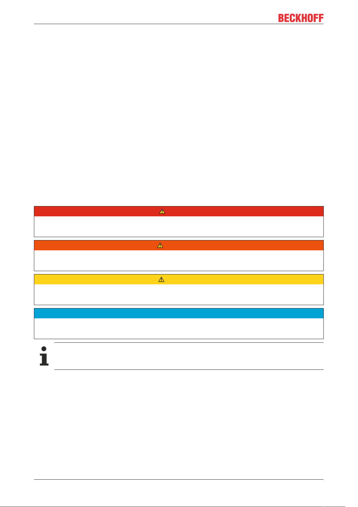
Fig.1: EtherCAT Box Modules within an EtherCAT network
The robust design of the EtherCAT Box modules enables them to be used directly at the machine. Control
cabinets and terminal boxes are now no longer required. The modules are fully sealed and therefore ideally
prepared for wet, dirty or dusty conditions.
Pre-assembled cables significantly simplify EtherCAT and signal wiring. Very few wiring errors are made, so
that commissioning is optimized. In addition to pre-assembled EtherCAT, power and sensor cables, fieldconfigurable connectors and cables are available for maximum flexibility. Depending on the application, the
sensors and actuators are connected through M8 or M12connectors.
The EtherCAT modules cover the typical range of requirements for I/O signals with protection class IP67:
• digital inputs with different filters (3.0ms or 10μs)
• digital outputs with 0.5 or 2A output current
• analog inputs and outputs with 16bit resolution
• Thermocouple and RTD inputs
• Stepper motor modules
XFC (eXtreme Fast Control Technology) modules, including inputs with time stamp, are also available.
EP7342-00028 Version: 1.0
Page 9
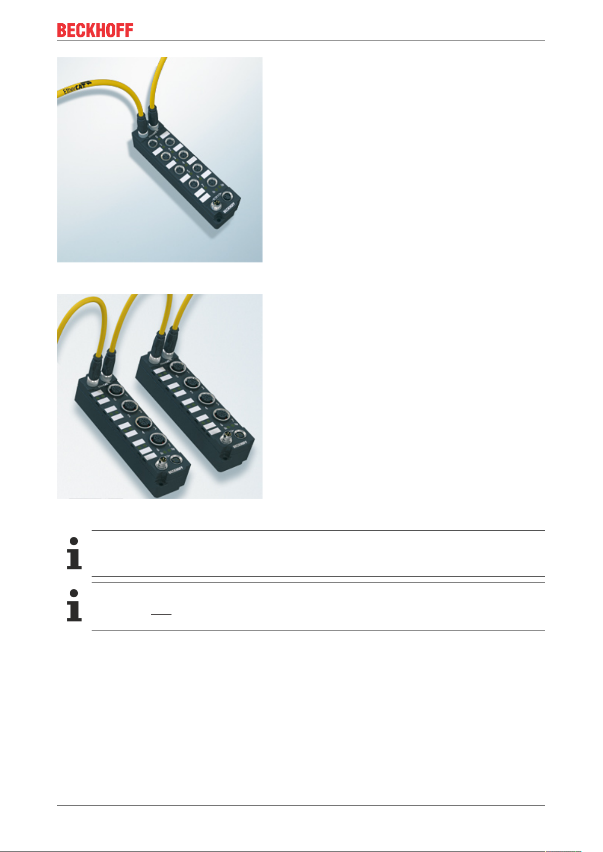
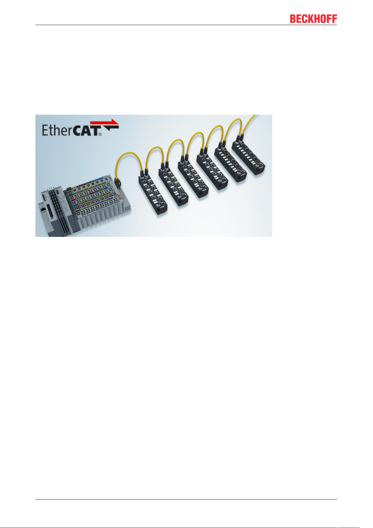
Fig.2: EtherCAT Box with M8 connections for sensors/actuators
EtherCAT Box - Introduction
Fig.3: EtherCAT Box with M12 connections for sensors/actuators
Basic EtherCAT documentation
You will find a detailed description of the EtherCAT system in the Basic System Documentation for
EtherCAT, which is available for download from our website (www.beckhoff.com) under Downloads.
EtherCAT XML Device Description
You will find XML files (XML Device Description Files) for Beckhoff EtherCAT modules on our website (www.beckhoff.com) under Downloads, in the Configuration Files area.
EP7342-0002 9Version: 1.0
Page 10
Product overview
3 Product overview
3.1 Introduction
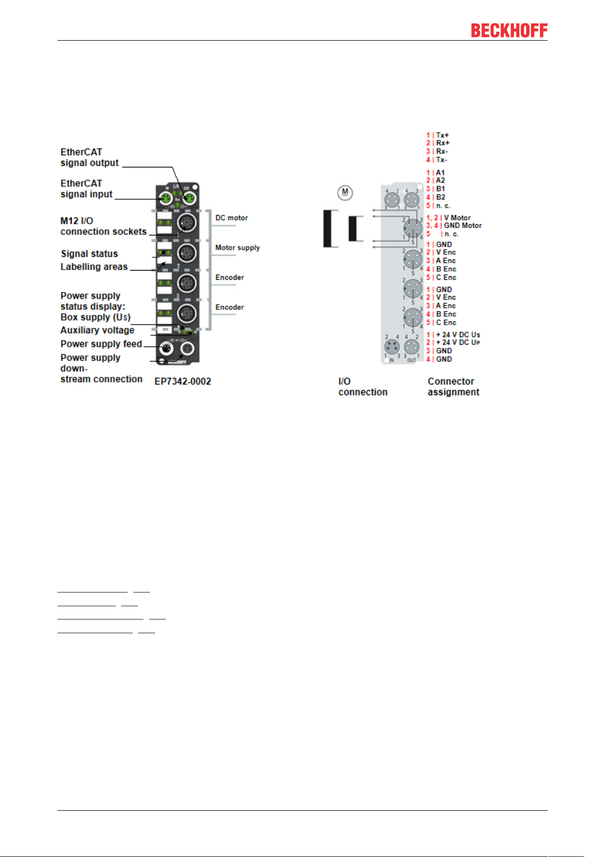
Fig.4: EP7342-0002
2-channel DC motor output stage 48 VDC, 3.5 A
The EP7342 EtherCAT Box enables direct operation of two DC motors.
The speed and position are preset by a 16-bit value from the automation device. By connecting an
incremental encoder (24 V DC, single-ended), it is possible to implement a simple servo axis. The output
stage is protected against overload and short-circuit.
The EtherCAT Box has two channels, whose signal states are indicated by LEDs. The LEDs enable quick
local diagnosis.
Quick links
Technical data [}11]
Dimensions [}15]
Signal connection [}21]
Commissioning [}26]
EP7342-000210 Version: 1.0
Page 11

Product overview
3.2 Technical data
All values are typical values over the entire temperature range, unless stated otherwise.
Technical data EP7342-0002
Fieldbus
Fieldbus EtherCAT
Connection 2x M8 socket, 4-pin, green
Distributed Clocks yes
Electrical isolation 500V (fieldbus/ IO)
Supply voltages
Connection Input: 1 x M8 plug, 4-pin
Downstream connection: 1 x M8 socket, 4-pin
Motor supply: 1x M12 socket, 4-pin
Control voltage U
Nominal voltage 24VDC (-15%/ +20%)
Sum current max. 4A
Current consumption from U
Peripheral voltage U
Nominal voltage 24VDC (-15%/ +20%)
Sum current max. 4A
UP consumer Encoder
Motor supply
Nominal voltage 8…48V
Motor outputs
Number 2
Motor type DC brush motor, inductive
Connection 1x M12 common socket for both motors
Motor supply see above under "Supply voltages“
Nominal current per output 3.5A, short-circuit proof
Overload protection Thermal overload warning
Resolution Current: max. 10bits
PWM clock frequency 30kHz with 180° phase shift each
PWM duty cycle 0…100 % (voltage-controlled)
Current controller frequency approx. 25kHz
Encoder inputs
Number 2
Encoder type Incremental encoders
Connection 1x M12 socket per encoder
Encoder supply 24VDC taken from the peripheral voltage UP, not short-circuit
signals Single-ended
Signal voltage "0" -3…1.5V
Signal voltage "1" 2.5…24V
Pulse frequency max. 400,000increments per second with 4-fold evaluation
S
1)
S
P
120mA
1)
DC
Speed: max. 16 bits
proof
1)
This value corresponds to the current carrying capacity of the connections for the supply voltages.
EP7342-0002 11Version: 1.0
Page 12

Product overview
Technical data EP7342-0002
Environmental conditions
Ambient temperature during operation -25…+60°C
0...+55 °C according to ATEX [}23]
Ambient temperature during storage -40…+85°C
Vibration/ shock resistance conforms to EN60068-2-6 / EN60068-2-27;
see also Additional checks [}12].
EMC immunity/emission conforms to EN61000-6-2/ EN61000-6-4
Protection class IP65, IP66, IP67 conforms to EN60529
Mechanics
Weight approx. 165g
Dimensions approx. 126x 30x 26.5mm (without connectors)
Installation position variable
Approvals and conformity
Approvals CE, ATEX
Additional checks
The boxes have been subjected to the following checks:
Verification Explanation
Vibration 10 frequency sweeps in 3 axes
5Hz<f<60Hz displacement 0.35mm, constant amplitude
60.1Hz<f<500Hz acceleration 5g, constant amplitude
Shocks 1000 shocks in each direction, in 3 axes
35g, 11ms
3.3 Scope of supply
Make sure that the following components are included in the scope of delivery:
• 1x EP7342-0002 EtherCAT Box
• 2x protective cap for EtherCAT socket, M8, green (pre-assembled)
• 1x protective cap for supply voltage input, M8, transparent (pre-assembled)
• 1x protective cap for supply voltage output, M8, black (pre-assembled)
• 10x labels, blank (1 strip of 10)
Pre-assembled protective caps do not ensure IP67 protection
Protective caps are pre-assembled at the factory to protect connectors during transport. They may
not be tight enough to ensure IP67 protection.
Ensure that the protective caps are correctly seated to ensure IP67 protection.
EP7342-000212 Version: 1.0
Page 13

Product overview
3.4 Technology
EP7342-0002 integrates a compact Motion Control solution up to 200W with minimum space requirement.
DC motor
DC motors can replace the considerably more expensive servo motors in many applications if they are
operated with an intelligent controller. Since its speed is proportional to the voltage, the DC motor is easy to
control in comparison with other motors.
Two output stages for optimum performance
With the EP7342 EtherCAT Box a DC motor can easily be integrated into the control system. All parameters
are adjustable via the fieldbus. The DC motor output stages for EtherCAT unite a small, compact design with
an extensive area of application. Two DC motors can be operated directly with each of the output stages.
The EP7342 also has an integrated feedback system for incremental encoders.
The speed can be easily adjusted via the process data. The integrated compensation of the internal
resistance keeps the motor at the desired speed for load changes. The speed is preset by a 16-bit value
from the automation device. Thus a simple drive task can be solved using a simple controller.
The EtherCAT Box has two channels, whose signal states are indicated by LEDs. This enables fast local
diagnosis.
EP7342-0002 13Version: 1.0
Page 14
Product overview
EP7342
EP7342
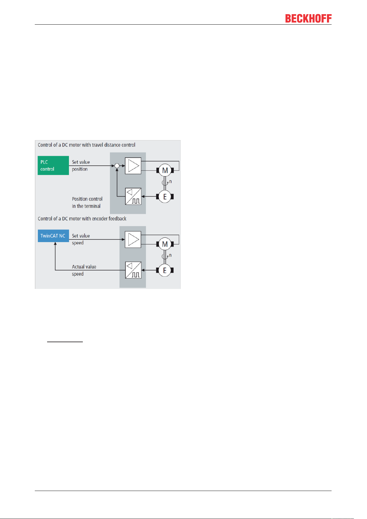
Areas of application
Two areas of application are particularly well supported by the output stages:
1. A simple controller with inexpensive processor power and low demands on the cycle time.
By using the integrated path control, the box can carry out independent positioning movements without the use of NC. Only a DC motor and the EtherCAT Box are required.
2. High-end positioning with integration in TwinCAT NC.
In conjunction with EP7342, a DC motor is controlled under TwinCAT like a servo terminal. No further
changes are necessary.
For demanding positioning tasks a closed speed control loop with a feedback system is needed. The
EtherCAT Box enables connection of an incremental encoder.
The control loop can be closed either by the EtherCAT Box itself or by the higher-level control system.
Fig.5: Implementation options for control loops with EP7342-0002
The peak current may briefly significantly exceed the nominal current and in this way makes the whole drive
system very dynamic. In such dynamic applications, negative acceleration causes energy recovery, which
lead to voltage peaks at the power supply unit.
The EP9576-1032 brake chopper box protects against the consequences of overvoltage by absorbing part of
the energy: It has an integrated brake resistor that converts surplus energy into heat.
EP7342-000214 Version: 1.0
Page 15
4 Mounting and connection
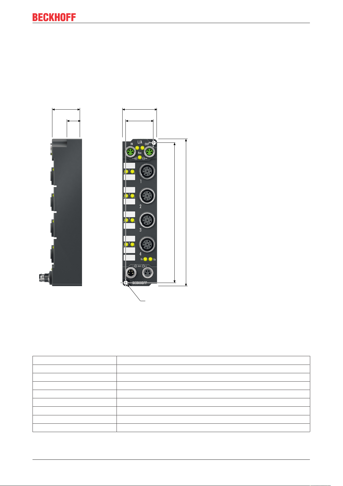
119
126
23
30
26.5
13.5
Ø 3.5
4.1 Mounting
4.1.1 Dimensions
Mounting and connection
Fig.6: Dimensions
All dimensions are given in millimeters.
Housing features
Housing material PA6 (polyamide)
Sealing compound polyurethane
Mounting two fastening holes Ø 3.5 mm for M3
Metal parts brass, nickel-plated
Contacts CuZn, gold-plated
Power feed through max. 4A
Installation position variable
Protection class IP65, IP66, IP67 (conforms to EN 60529) when screwed together
Dimensions (H x W x D) approx. 126 x 30 x 26.5 mm (without connectors)
EP7342-0002 15Version: 1.0
Page 16

Mounting and connection
4.1.2 Fixing
NOTE
Dirt during assembly
Dirty connectors can lead to malfunctions. Protection class IP67 can only be guaranteed if all cables and
connectors are connected.
• Protect the plug connectors against dirt during the assembly.
Mount the module with two M3 screws on the fastening holes in the corners of the module. The fastening
holes have no thread.
4.1.3 Tightening torques for plug connectors
Screw connectors tight with a torque wrench. (e.g. ZB8801 from Beckhoff)
Connector diameter Tightening torque
M8 0.4Nm
M12 0.6Nm
EP7342-000216 Version: 1.0
Page 17
Mounting and connection
3 1
24
4.2 Connection
4.2.1 EtherCAT
4.2.1.1 Connectors
NOTE
Risk of confusion: supply voltages and EtherCAT
Defect possible through incorrect insertion.
• Observe the color coding of the connectors:
black: Supply voltages
green: EtherCAT
EtherCAT Box Modules have two green M8 sockets for the incoming and downstream EtherCAT
connections.
Fig.7: EtherCAT connectors
Connection
Fig.8: M8 socket
EtherCAT M8
Signal Contact ZB9010, ZB9020, ZB9030, ZB9032,
Tx + 1 yellow
Tx - 4 orange
Rx + 2 white
Rx - 3 blue
Shield Housing Shield Shield Shield
1)
Core colors according to EN61918
connector
Core colors
ZK1090-6292,
ZK1090-3xxx-xxxx
1)
1)
1)
1)
ZB9031 and old versions of
ZB9030, ZB9032, ZK1090-3xxxxxxx
orange/white white/orange
orange orange
blue/white white/green
blue green
TIA-568B
Adaptation of core colors for cables ZB9030, ZB9032 and ZK1090-3xxxx-xxxx
For standardization, the core colors of the ZB9030, ZB9032 and ZK1090-3xxx-xxxx cables have
been changed to the EN61918 core colors: yellow, orange, white, blue. So there are different color
codes in circulation. The electrical properties of the cables have been retained when the core colors
were changed.
EP7342-0002 17Version: 1.0
Page 18
Mounting and connection
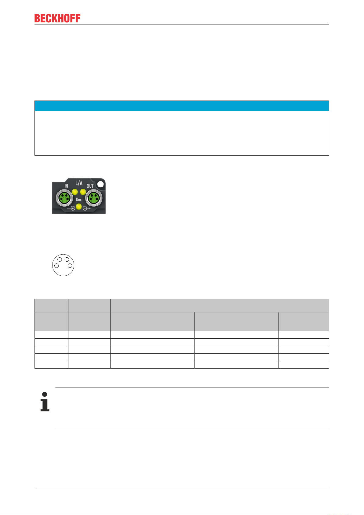
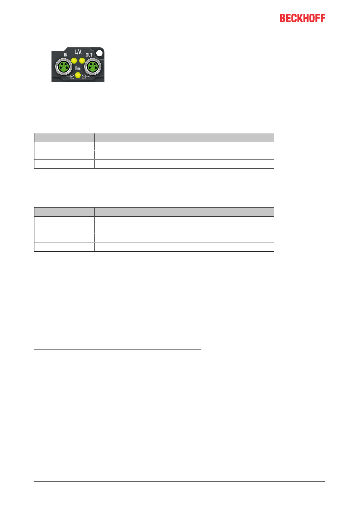
4.2.1.2 Status LEDs
Fig.9: EtherCAT status LEDs
L/A (Link/Act)
A green LED labelled "L/A" is located next to each EtherCAT socket. The LED indicates the communication
state of the respective socket:
LED Meaning
off no connection to the connected EtherCAT device
lit LINK: connection to the connected EtherCAT device
flashes ACT: communication with the connected EtherCAT device
Run
Each EtherCAT slave has a green LED labelled "Run". The LED signals the status of the slave in the
EtherCAT network:
LED Meaning
off Slave is in "Init" state
flashes uniformly Slave is in "Pre-Operational“ state
flashes sporadically Slave is in "Safe-Operational" state
lit Slave is in "Operational" state
Description of the EtherCAT slave states
4.2.1.3 Cables
For connecting EtherCAT devices only shielded Ethernet cables that meet the requirements of at least
category5 (CAT5) according to EN50173 or ISO/IEC11801 should be used.
EtherCAT uses four wires for signal transmission.
Thanks to automatic line detection ("Auto MDI-X"), both symmetrical (1:1) or cross-over cables can be used
between Beckhoff EtherCAT.
Detailed recommendations for the cabling of EtherCAT devices
EP7342-000218 Version: 1.0
Page 19
Mounting and connection
Plug
Input
Socket
Forwarding
3 1
24
3 1
24
4.2.2 Supply voltages
The EtherCAT Box is supplied with two supply voltages. The ground potentials of the supply voltages are
galvanically connected together.
• Control voltage U
• Peripheral voltage U
S
P
The motor supply must be provided separately.
See chapter Signal connection [}21].
Redirection of the supply voltages
The IN and OUT power connections are bridged in the module (not IP204x-Bxxx and IE204x). The supply
voltages US and UP can thus easily be transferred from EtherCATBox to EtherCATBox.
NOTE
Pay attention to the maximum permissible current!
Pay attention also for the redirection of the supply voltages US and UP, the maximum permissible current for
M8 connectors of 4A must not be exceeded!
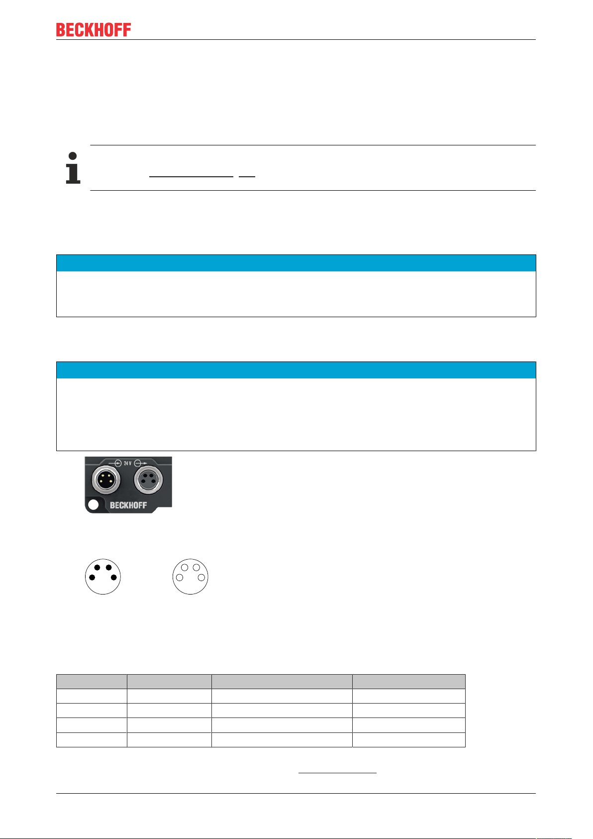
4.2.2.1 Connectors
NOTE
Risk of confusion: supply voltages and EtherCAT
Defect possible through incorrect insertion.
• Observe the color coding of the connectors:
black: Supply voltages
green: EtherCAT
Fig.10: Connectors for supply voltages
Fig.11: M8 connector
Contact Function Description Core color
1 U
2 U
3 GND
4 GND
1)
The core colors apply to cables of the type: Beckhoff ZK2020-3xxx-xxxx
EP7342-0002 19Version: 1.0
S
P
S
P
Control voltage Brown
Peripheral voltage White
GND to U
GND to U
S
P
Blue
Black
1)
Page 20
Mounting and connection
Vert. Faktor: 0,45 cm / V
5 10 15 20
2
4
6
8
10
250
0
12
30
Vert. Faktor: 0,45 cm / V
Voltage drop (V)
Cable length (m)
35
0,25 mm²
0,34 mm²
0,5 mm²
0,75 mm²
I = 2 A
Vert. Faktor: 0,45 cm / V
5 10 15 20
2
4
6
8
10
250
0
12
30
Vert. Faktor: 0,45 cm / V
Voltage drop (V)
Cable length (m)
35
0,25 mm²
0,34 mm²
0,5 mm²
0,75 mm²
I = 4 A
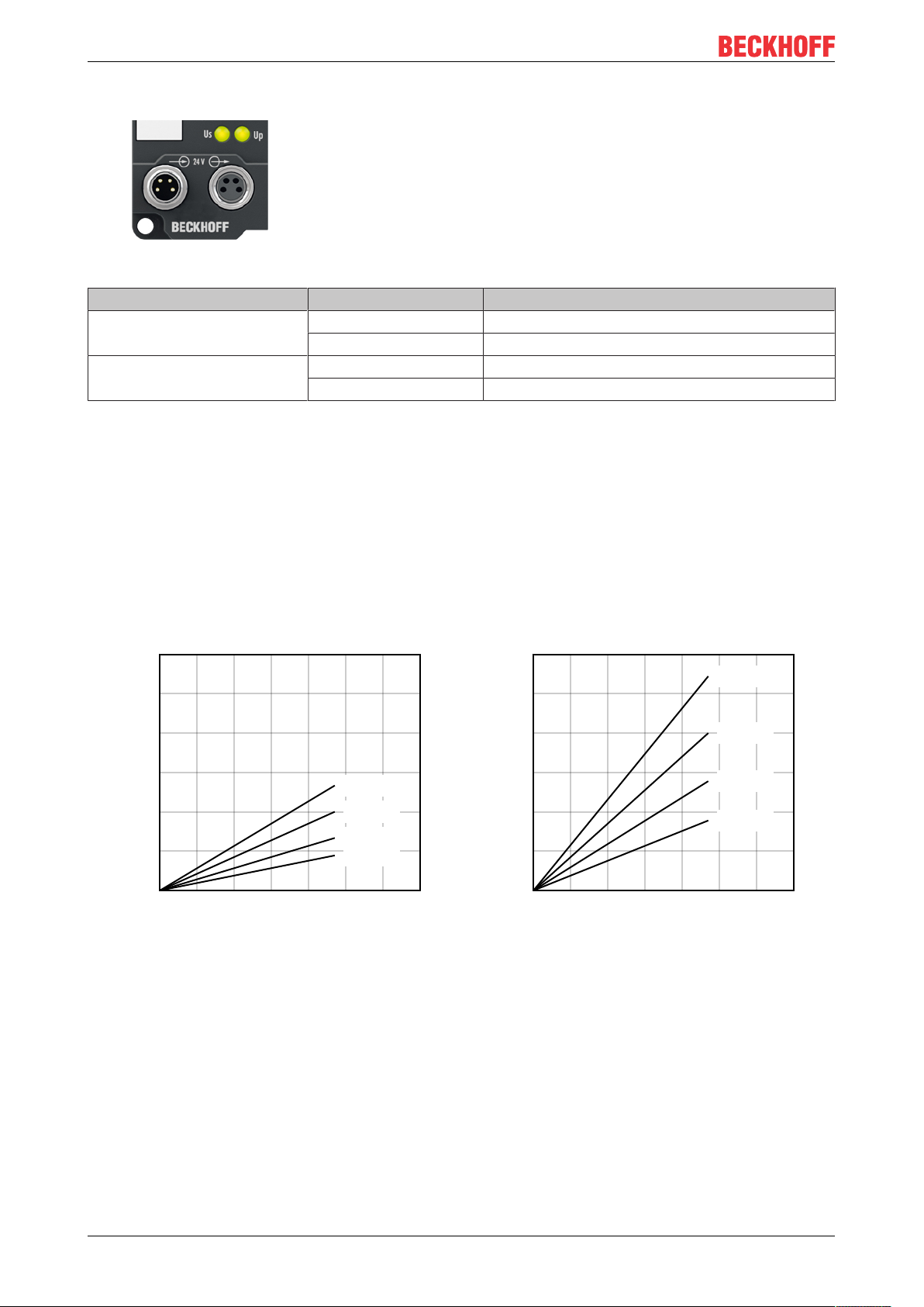
4.2.2.2 Status LEDs
Fig.12: Status LEDs for the supply voltages
LED Display Meaning
US (control voltage) off Supply voltage US is not present
green illuminated Supply voltage US is present
UP (peripheral voltage) off Supply voltage UP is not present
green illuminated Supply voltage UP is present
4.2.2.3 Conductor losses
Take into account the voltage drop on the supply line when planning a system. Avoid the voltage drop being
so high that the supply voltage at the box lies below the minimum nominal voltage.
Variations in the voltage of the power supply unit must also be taken into account.
Voltage drop on the supply line
EP7342-000220 Version: 1.0
Page 21
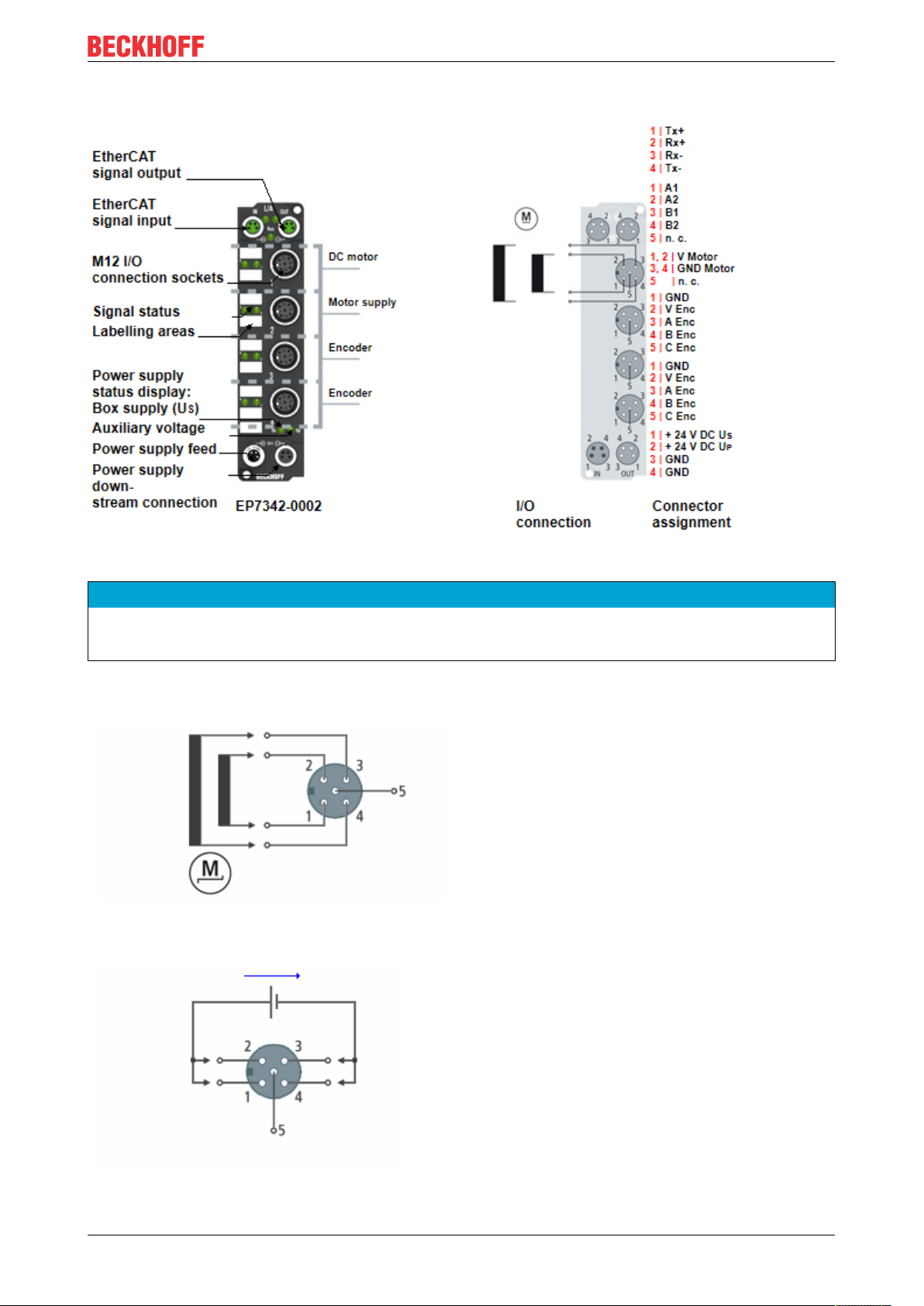
4.2.3 Signal connection
Mounting and connection
Fig.13: Signal connection EP7342-0002
NOTE
Note the numbering of the M12 sockets
Mixing up the M12 connectors can damage the module.
M12 socket no.1: DC motor connection
M12 socket no.2: Connection for motor supply
Pin 1: Motor channel1, connection1
Pin 2: Motor channel1, connection2
Pin 3: Motor channel2, connection1
Pin 4: Motor channel2, connection2
Pin 5: not connected
Pin 1: Motor supply 8...48 V
Pin 2: Motor supply 8...48 V
DC
DC
Pin 3: GND
Pin 4: GND
Pin 5: not connected
EP7342-0002 21Version: 1.0
Page 22

Mounting and connection
M12 sockets no. 3 and no. 4: Encoder connection
The encoder supply is not short-circuit proof
Risk of defect.
• Avoid short-circuiting the encoder supply.
NOTE
Pin 1: GND
Pin 2: Encoder supply 24 V
Pin 3: Track A
Pin 4: Track B
Pin 5: Track C (Gate/Latch)
DC
EP7342-000222 Version: 1.0
Page 23
Mounting and connection
4.3 ATEX notes
4.3.1 ATEX - Special conditions
WARNING
Observe the special conditions for the intended use of EtherCAT Box modules in potentially explosive areas – directive 94/9/EU.
• The certified components are to be installed with a BG2000-0000 or BG2000-0010 protection enclosure
[}24] that guarantees a protection against mechanical hazards!
• If the temperatures during rated operation are higher than 70°C at the feed-in points of cables, lines or
pipes, or higher than 80°C at the wire branching points, then cables must be selected whose temperature data correspond to the actual measured temperature values!
• Observe the permissible ambient temperature range of 0 to 55°C for the use of EtherCAT Box modules
in potentially explosive areas!
• Measures must be taken to protect against the rated operating voltage being exceeded by more than
40% due to short-term interference voltages!
• The connections of the certified components may only be connected or disconnected if the supply voltage has been switched off or if a non-explosive atmosphere is ensured!
Standards
The fundamental health and safety requirements are fulfilled by compliance with the following standards:
• EN 60079-0: 2006
• EN 60079-15: 2005
Marking
The EtherCAT Box modules certified for potentially explosive areas bear the following marking:
II 3 GEx nA II T4DEKRA 11ATEX0080 XTa: 0 - 55°C
or
II 3 GEx nA nC IIC T4DEKRA 11ATEX0080 XTa: 0 - 55°C
Batch number (D number)
The EtherCAT Box modules bear a batch number (D number) that is structured as follows:
D: WW YY FF HH
WW - week of production (calendar week)
YY - year of production
FF - firmware version
HH - hardware version
Example with batch number 29 10 02 01:
29 - week of production 29
10 - year of production 2010
02 - firmware version 02
01 - hardware version 01
EP7342-0002 23Version: 1.0
Page 24
Mounting and connection
4.3.2 BG2000 - EtherCAT Box protection enclosures
WARNING
Risk of electric shock and damage of device!
Bring the EtherCAT system into a safe, powered down state before starting installation, disassembly or
wiring of the modules!
ATEX
WARNING
Mount a protection enclosure!
To fulfill the special conditions according to ATEX [}23], a BG2000-0000 or BG2000-0010 protection enclosure has to be mounted over the EtherCAT Box.
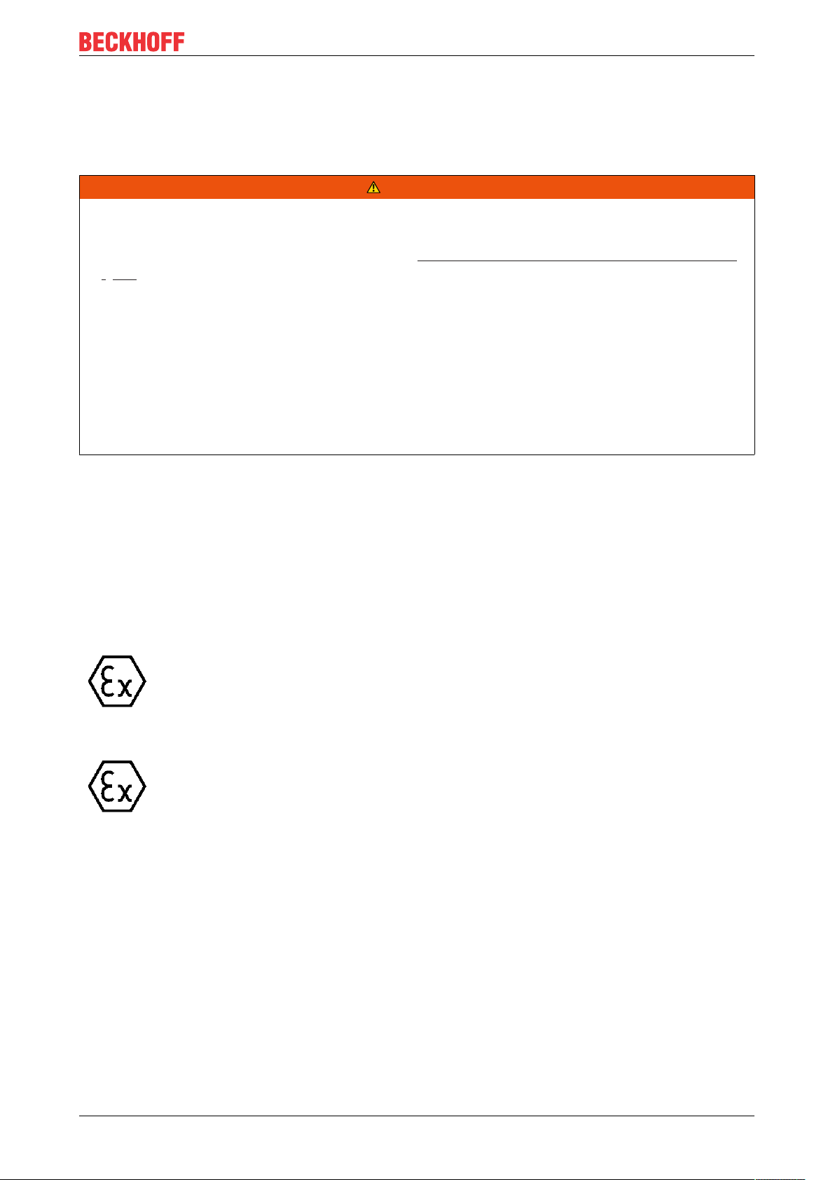
Installation
Put the cables for EtherCAT, power supply and sensors/actuators through the hole of the protection
enclosure.
Fig.14: BG2000 - putting the cables
Fix the wires for EtherCAT, power supply and sensors/actuators to the EtherCAT Box.
EP7342-000224 Version: 1.0
Page 25
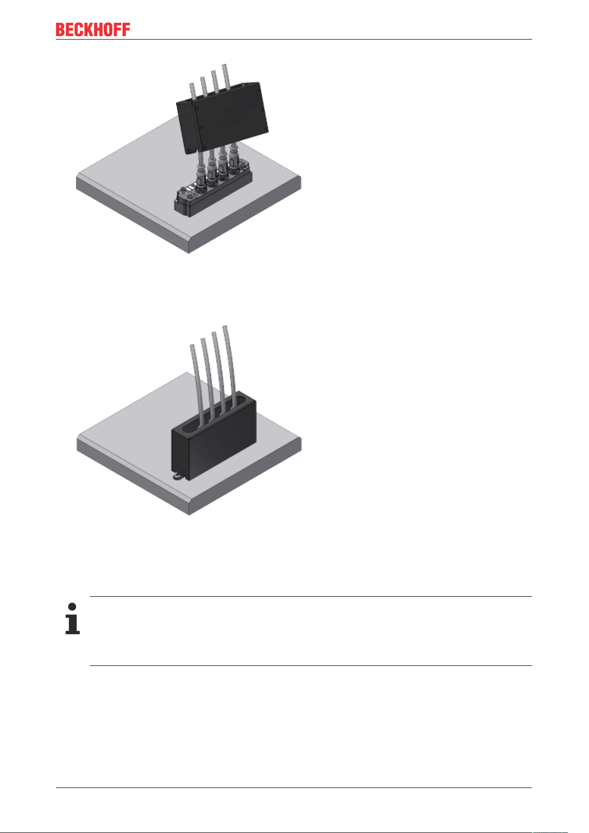
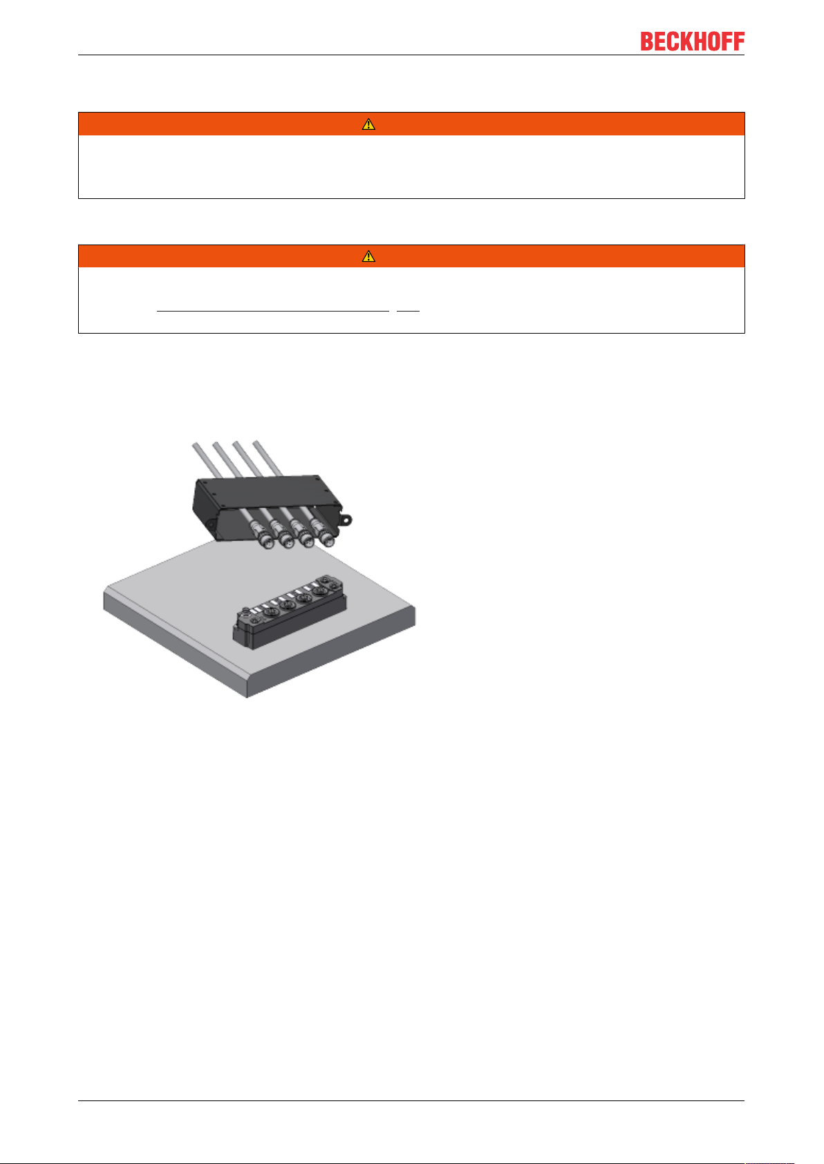
Fig.15: BG2000 - fixing the cables
Mount the protection enclosure over the EtherCAT Box.
Mounting and connection
Fig.16: BG2000 - mounting the protection enclosure
4.3.3 ATEX Documentation
Notes about operation of EtherCAT Box Modules (EPxxxx-xxxx) in potentially explosive areas (ATEX)
Pay also attention to the continuative documentationNotes about operation of EtherCAT Box Modules (EPxxxx-xxxx) in potentially explosive areas (ATEX) that is available in the download area of
the Beckhoff homepage http:\\www.beckhoff.com!
EP7342-0002 25Version: 1.0
Page 26
Commissioning/Configuration
5 Commissioning/Configuration
5.1 Integration in TwinCAT
The procedure for integration in TwinCAT is described in this Quick start guide.
5.2 Integration into the NC configuration (manually)
(TwinCAT 3.1)
EtherCAT XML Device Description
The display matches that of the CoE objects from the EtherCAT XML Device Description. We recommend downloading the latest XML file from the download area of the Beckhoff website and installing it according to installation instructions.
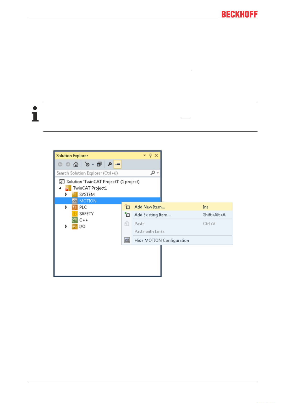
ü Requirement: EP7342 is integrated in a TwinCAT project.
1. Add a new NC task: Right-click on "MOTION" and select "Add New Item..."
EP7342-000226 Version: 1.0
Page 27
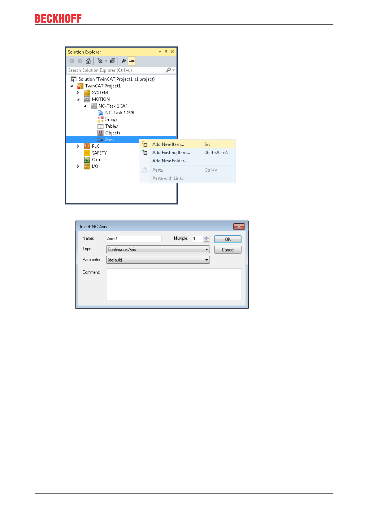
2. Right click on "Axes" and click on "Add New Item…“
Commissioning/Configuration
ð A dialog box appears:
3. In the "Type" field select "Continuous axis" and confirm with OK.
4. Double-click the new axis.
5. Click on the "Settings" tab
EP7342-0002 27Version: 1.0
Page 28
Commissioning/Configuration
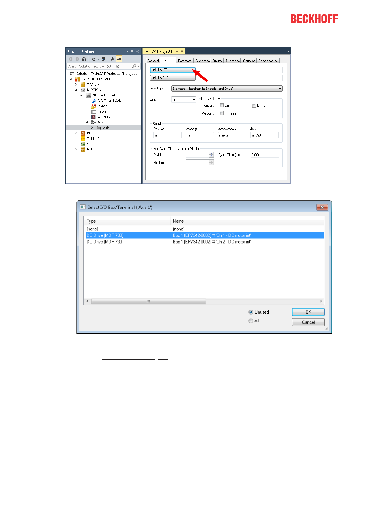
6. Click on "Link To I/O..."
ð A dialog box appears:
7. Select the appropriate entry and click "OK".
Note: EP7342 has two motor channels. The assignment of the connector pins to the motor channels can
be found in chapter Signal connection [}21].
ð The process data are linked to the NC task.
You need to set some parameters before you can start the motor. You will find these parameters in the
following chapters:
• Settings in the CoE register [}29]
• NC settings [}35]
EP7342-000228 Version: 1.0
Page 29
Commissioning/Configuration
5.3 Settings in the CoE register
The data given here exemplary for a DC motor type GR42X25 from the company Dunkermotoren. For other
motors the values may vary, depending on the application.
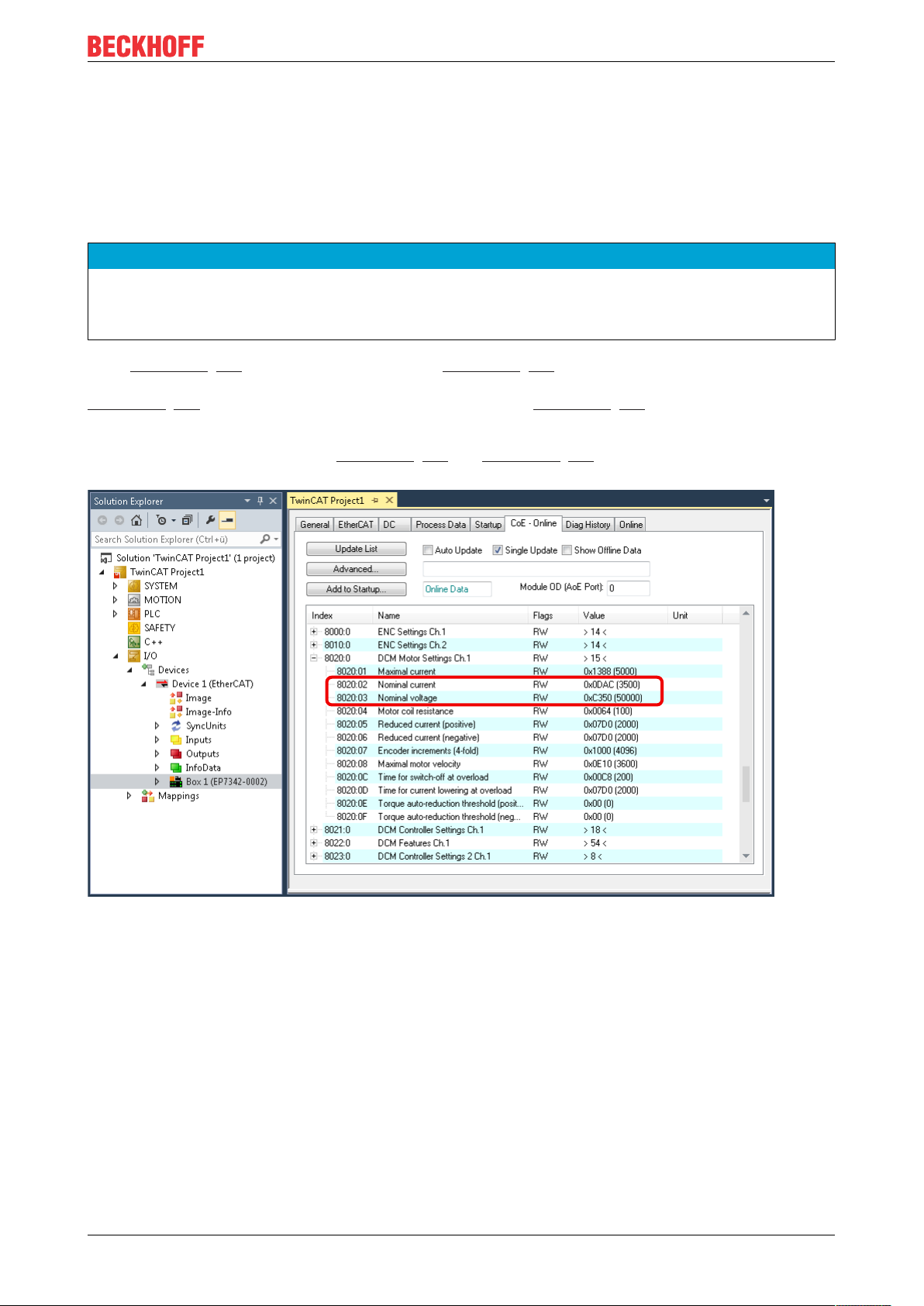
5.3.1 Adaptation of current and voltage
NOTE
The motor may overheat!
In order to prevent overheating of the connected motor it is important to adapt the current and voltage output from the stepper interface to the motor.
Index 0x8020:02 [}49] "Nominal current" and index 0x8020:03 [}49] "Nominal voltage" have be set
appropriately in the CoE register. In addition, you should also adapt the "Maximal current" in the index
0x8020:01 [}49] and the coil resistance of the motor in the index 0x8020:04 [}49] "Motor coil resistance"
to the connected motor.
Reducedcurrent can be set in index 0x8020:05 [}49] and 0x8020:06 [}49]. This reduces the coil current
when at a standstill (and therefore the power dissipation). Please note that this reduces the torque.
Fig.17: Adaptation of current and voltage
EP7342-0002 29Version: 1.0
Page 30
Commissioning/Configuration
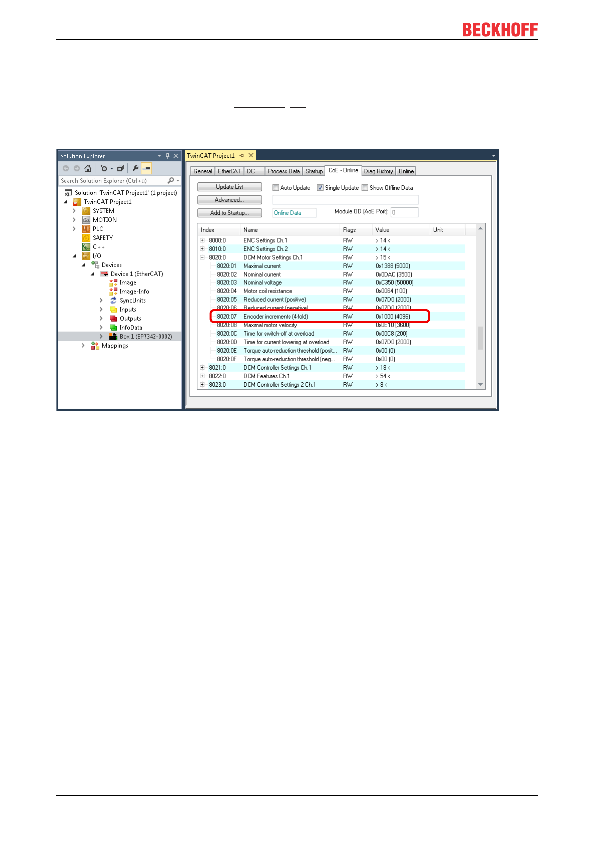
5.3.2 Adaptation of the encoder data
Different encoders are available with a different number of increments. You must specify the number of
increments of your encoder in the index 0x8020:07 [}49] "Encoder increments" (see fig. Adaptation of the
encoder data). In our example an encoder with 1024 increments is used, corresponding to 4096 increments
in the case of quadruple evaluation. The number of increments of your encoder can be found in the data
sheet for the encoder.
Fig.18: Adaptation of the encoder data
EP7342-000230 Version: 1.0
Page 31

Commissioning/Configuration
5.3.3 Adaptation of the maximal velocity
The maximum velocity with which your DC motor can move must be entered in index 0x8020:08 [}49]
"Maximum motor velocity". You can take this parameter from the name plate on the motor and write it 1:1
into the index. In the example the motor has a maximum velocity of 3600 revolutions per minute.
Fig.19: Adaptation of the maximal velocity
EP7342-0002 31Version: 1.0
Page 32

Commissioning/Configuration
5.3.4 Selection of the operating mode
You can select the operating mode in the index 0x8022:01 [}51] "Operation mode". It is recommended that
you select the operation mode "Automatic" (Fig. Setting the operation mode) and then set the suitable
operation mode for your application on the Process Data tab. Further information on this can be found in the
chapter "Process Data".
Fig.20: Setting the operation mode
Fig.21: Dialog box
EP7342-000232 Version: 1.0
Page 33

Commissioning/Configuration
5.3.5 Select info data
There is a possibility in the index 0x8022:11 [}51] "Select info data 1" and 0x8022:19 [}51] "Select info
data 2", to select two parameters that can be displayed in the process data (see fig. Selection of additional
information data).
These two parameters must be activated in the process data afterwards.
Fig.22: Selection of additional information data
Fig.23: Dialog box
EP7342-0002 33Version: 1.0
Page 34

Commissioning/Configuration
5.3.6 KA factor
The KA factor can be used to adapt the current during the acceleration phases. The current increase is
calculated as follows.
Current increaseinmA=velocity differencexKA/1000
The steeper the velocity ramp, the higher the current increase.
Fig.24: Velocity ramps
This value can be set in index 0x8023:07 [}52] "Ka factor (velo./pos.)" (see Fig. Setting the KA factor).
Fig.25: Setting the KA factor
EP7342-000234 Version: 1.0
Page 35

Commissioning/Configuration
5.4 NC settings
The specified data apply to a DC Motor GR42X25 of the Company "Dunker Motoren" and are intended as an
example. For other motors the values may vary, depending on the application.
5.4.1 Reference velocity selection
The maximum velocity is calculated based on the maximum motor speed (see name plate) and the distance
to be covered. In this case the basis is one revolution per second.
v
=(maximum motor velocity x 360°) / 60s
max
=((3600rpm)x360°)/60s
=21600revolutions/s
This is a theoretical value that is quite close to the practical value, although the value may vary, depending
on the load. To determine the actual value set the Kv factor to 0 and determine the final reference velocity
empirically. To this end move the motor using the keys F1 - F4 and compare the actual velocity and the
setpoint velocity. These values should be almost identical. If the actual velocity is greater, increase the
reference velocity slightly. If the Actual velocity is smaller than the Setpoint velocity, reduce the reference
velocity slightly. This empirical exercise should only be carried out once the other parameters have been set.
In our case the reference velocity is 25570 revolutions/s. Finally, adjust the maximum allowed velocity.
Fig.26: Reference velocity selection
EP7342-0002 35Version: 1.0
Page 36

Commissioning/Configuration
5.4.2 Dead time compensation
Dead time compensation
The dead time compensation of the axis can be set in the Time Compensation tab of the Axis1_ENC
encoder settings. It should, in theory, be 3 cycles of the NC cycle time, although in practice 4 cycles were
found to be preferable. The parameter Time Compensation Mode Encoder should be set to 'ON (with
velocity)', the parameter Encoder Delay in Cycles to 4.
Fig.27: Dead time compensation parameter
EP7342-000236 Version: 1.0
Page 37

Commissioning/Configuration
5.4.3 Scaling factor
The scaling factor can be changed by selecting "Axis 1_Enc" and tab "Parameter" in the NC (see fig. Setting
the Scaling Factor). The value can be calculated with the formulas specified below.
Fig.28: Setting the Scaling Factor
Calculation of the scaling factor
SF = distance per revolution / (increments x 4) = 360° / (1024 x 4) = 0.087890625 ° / INC
EP7342-0002 37Version: 1.0
Page 38

Commissioning/Configuration
5.4.4 Position lag monitoring
The position lag monitoring function checks whether the current position lag of an axis has exceeded the
limit value. The position lag is the difference between the setpoint (control value) and the actual value
reported back. Suboptimal parameter settings can lead to an error in position lag monitoring during the axis
movement. During commissioning it may therefore be advisable to increase the "Maximum Position Lag
Value" slightly.
NOTE
CAUTION: Damage to equipment, machines and peripheral components possible!
Setting the position lag monitoring parameters too high may result in damage to equipment, machines and
peripheral components.
Fig.29: Position lag monitoring
EP7342-000238 Version: 1.0
Page 39

Commissioning/Configuration
5.4.5 KV factors
In the NC two proportional factors Kv can be set under "Axis 1_Ctrl " in tab "Parameter". First select the
position controller Type with two P constants (with KA) under the "NC Controller" tab. The two P constants
are for the Standstill range and for the Moving range (see Fig. Setting the proportional factor KV). The
factors can be used to set the start-up torque and the braking torque to a different value than the drive
torque. The threshold value can be set directly below (Position control: Velocity threshold V dyn) between
0.0 (0%) and 1.0 (100%). Fig. Velocity ramp with KV factor limit values shows a speed ramp with thresholds
of 50%. The Kv factor for Standstill (t1 and t3) can be different than the Kv factor for Moving (t2). The factor at
standstill should always be greater than the factor during motion.
Fig.30: Velocity ramp with KV factor limit values
Fig.31: Setting the proportional factor K
v
EP7342-0002 39Version: 1.0
Page 40

Commissioning/Configuration
1.
2.
5.5 Commissioning the motor with the NC
Enabling an axis
• Once the parameters are set, the motor is basically ready for operation. Individual further parameters
have to be adapted to the respective application.
• To commission the axis, activate the configuration (Ctrl+Shift+F4), select the axis, select tab Online
and enable the axis under Set.
• Set all tick marks and set Override to 100% (see Fig. Enabling an axis). The axis can then be moved.
Fig.32: Enabling an axis
Move axis manually
You can now move the axis with the function keys F1, F2 (Backward) or F3, F4 (Forward).
You can adjust the Kv factor in order to approach a suitable factor. Set the value to 0 initially in order to set
the correct reference velocity. For calculating the reference velocity please refer to section "Selecting the
reference velocity". The calculation provides a relatively precise value, although the value may have to be
corrected slightly. To this end move the motor with a Kv factor of 0 until the actual velocity matches the
setpoint velocity.
EP7342-000240 Version: 1.0
Page 41

Commissioning/Configuration
Move axis automatically
Alternatively you can control the axis via the "Functions" tab. An example is provided below.
• Select as Reversing Sequence as the start type.
• Enter the required Target Position1, e.g. 5000°.
• Enter the required Target Velocity, e.g. 2000°/s.
• Enter the required Target Position2, e.g. 0°.
• Enter the required Idle Time, e.g. 1s.
• Select Start.
The motor now turns to position 1, remains there for 1 s and returns to position 2. This is repeated until Stop
is pressed.
EP7342-0002 41Version: 1.0
Page 42

Commissioning/Configuration
5.6 Operating modes
5.6.1 Overview
The operating modes Automatic, Velocity direct, Position controller, Path control and Brake resistor are
supported.
Automatic
In preparation!
Velocity, direct
This mode is intended for the cyclic velocity interface of a numeric controller (NC). In this mode, the NC
specifies a set velocity. Ramps for start-up and deceleration of the motor are also controlled by the NC.
Position controller
Refer to the Positioning Interface [}45] section for information about this operation mode!
Travel distance control
In preparation!
Brake resistor
Refer to the Chopper operation [}43] section for information about this operation mode
EP7342-000242 Version: 1.0
Page 43

Commissioning/Configuration
5.6.2 Chopper operation
You can connect a brake resistor (chopper) to one of the two motor channels instead of a DC motor and
enable "Chopper resistor" mode for this channel.
The motor must actively brake for positioning tasks. The mechanical energy is thereby converted back into
electrical energy. Small amounts of energy are absorbed by a capacitor in EP7342. Further storage
capacities, for example in the power supply unit, can also take up energy. The feedback leads in each case
to a voltage increase.
In order to avoid overvoltage, a brake resistor can be connected to the EP7342 in order to dissipate the
surplus energy in the form of heat. When the voltage reaches 110% of the nominal voltage [}29], e.g. 55V,
the correctly set output stage sends a fast-pulsed current through the brake resistor (see diagram).
Fig.33: ICH/IN. - UCH/UN characteristic curve
NOTE
Dimensioning of the brake resistor
The brake resistor should be dimensioned such that it can withstand the expected heat development without damage.
A brake resistor of 10Ω is recommended, which results in a pulse current of approx. 5.5A to 6.5A. The
maximum expected continuous power is 125W. However, the value typically lies significantly below that.
Power estimation
PN = IN² x R
PN = (5A)² x 10Ω
PN = 250W
EP7342-0002 43Version: 1.0
Page 44

Commissioning/Configuration
A maximum duty cycle of 50 % is possible. This results in a maximum continuous power of 125W.
A motor efficiency of 80 % is usual in practice.
The motor thus converts 80 % of the rated electrical power into kinetic energy when accelerating.
Conversely, when braking, the motor (as a generator) converts 80 % of the kinetic energy into electrical
power.
This results in a practical braking power of:
PCH = PN/2 x 80/100 x 80/100
PCH = 125W x 80/100 x 80/100
PCH = 80W
EP7342-000244 Version: 1.0
Page 45

Commissioning/Configuration
5.6.3 Positioning Interface
The "Positioning Interface" offers the option to execute motion commands directly on the box.
NOTE
Commissioning
Commissioning of the EL7342 "Positioning Interface" can be transferred to EP7342-0002.
The commissioning procedure is described in the chapter on "Basic principles for the Positioning Interface" of the EL7342 documentation.
EP7342-0002 45Version: 1.0
Page 46

Commissioning/Configuration
5.7 Restoring the delivery state
To restore the delivery state for backup objects in ELxxxx terminals / EPxxxx- and EPPxxxx boxes, the CoE
object Restore default parameters, SubIndex 001 can be selected in the TwinCAT System Manager (Config
mode).
Fig.34: Selecting the Restore default parameters PDO
Double-click on SubIndex 001 to enter the Set Value dialog. Enter the value 1684107116 in field Dec or the
value 0x64616F6C in field Hex and confirm with OK.
All backup objects are reset to the delivery state.
Fig.35: Entering a restore value in the Set Value dialog
Alternative restore value
In some older terminals / boxes the backup objects can be switched with an alternative restore
value:
Decimal value: 1819238756
Hexadecimal value: 0x6C6F6164
An incorrect entry for the restore value has no effect.
EP7342-000246 Version: 1.0
Page 47

Commissioning/Configuration
5.8 Decommissioning
WARNING
Risk of electric shock!
Bring the bus system into a safe, de-energized state before starting disassembly of the devices!
Disposal
In order to dispose of the device, it must be removed.
In accordance with the WEEE Directive 2012/19/EU, Beckhoff takes back old devices and accessories in
Germany for proper disposal. Transport costs will be borne by the sender.
Return the old devices with the note "for disposal" to:
Beckhoff Automation GmbH & Co. KG
Service Department
Stahlstraße 31
D-33415 Verl
EP7342-0002 47Version: 1.0
Page 48

CoE parameters
6 CoE parameters
EtherCAT XML Device Description
The display matches that of the CoE objects from the EtherCAT XML Device Description. We recommend downloading the latest XML file from the download area of the Beckhoff website and in-
stalling it according to installation instructions.
Parameterization via the CoE list (CAN over EtherCAT)
The EtherCAT device is parameterized via the CoE-Online tab (double-click on the respective object) or via the Process Data tab (allocation of PDOs). Please note the following general CoE notes
when using/manipulating the CoE parameters:
• Keep a startup list if components have to be replaced
• Differentiation between online/offline dictionary, existence of current XML description
• use “CoE reload” for resetting changes
Introduction
The CoE overview contains objects for different intended applications:
• Objects required for parameterization during commissioning:
◦ Restore object [}48]
◦ Configuration data
◦ Command object
• Profile-specific objects:
◦ Input data
◦ Output data
◦ Information and diagnosis data (channel specific)
◦ Configuration data (vendor-specific)
◦ Information and diagnosis data (device-specific)
• Standard objects
The following section first describes the objects required for normal operation, followed by a complete
overview of missing objects.
6.1 Restore object
Index 1011 Restore default parameters
Index
(hex)
1011:0 Restore default parame-
1011:01 SubIndex 001 If this object is set to “0x64616F6C” in the set value dia-
Name Meaning Data type Flags Default
Restore default parameters UINT8 RO 0x01 (1
ters
UINT32 RW 0x00000000 (0
log, all backup objects are reset to their delivery state.
)
dec
)
dec
EP7342-000248 Version: 1.0
Page 49

CoE parameters
6.2 Configuration data
Index 8000 ENC Settings Ch.1
Index (hex) Name Meaning Data type Flags Default
8000:0 ENC Settings Ch.1 Max. Subindex UINT8 RO 0x0E (14
8000:08 Disable filter 0: Activates the input filter (inputs A, /A, B, /B, C, /C
only)
1: Deactivates the input filter
If a filter is activated a signal edge must be present for
at least 2.4 µs in order to be counted as an increment.
8000:0A Enable micro incre-
ments
If activated, the terminal interpolates micro-increments
between the integral encoder increments in DC mode.
The lower 8 bits of the counter value are used in each
case for the display. A 32-bit counter thus becomes a
24+8-bit counter, a 16-bit counter becomes a 8+8-bit
counter.
8000:0E Reversion of rotation Activates reversion of rotation BOOLEAN RW 0x00 (0
Index 8010 ENC Settings Ch.2
Index (hex) Name Meaning Data type Flags Default
8010:0 ENC Settings Ch.2 Max. Subindex UINT8 RO 0x0E (14
8010:08 Disable filter 0: Activates the input filter (inputs A, /A, B, /B, C, /C
8010:0A Enable micro incre-
ments
8010:0E Reversion of rotation Activates reversion of rotation BOOLEAN RW 0x00 (0
only)
1: Deactivates the input filter
If a filter is activated a signal edge must be present for
at least 2.4 µs in order to be counted as an increment.
If activated, the terminal interpolates micro-increments
between the integral encoder increments in DC mode.
The lower 8 bits of the counter value are used in each
case for the display. A 32-bit counter thus becomes a
24+8-bit counter, a 16-bit counter becomes a 8+8-bit
counter.
BOOLEAN RW 0x00 (0
BOOLEAN RW 0x00 (0
BOOLEAN RW 0x00 (0
BOOLEAN RW 0x00 (0
)
dec
)
dec
)
dec
)
dec
)
dec
)
dec
)
dec
)
dec
Index 8020 DCM Motor Settings Ch.1
Index (hex) Name Meaning Data type Flags Default
8020:0 DCM Motor Settings
Ch.1
8020:01 Maximal current Maximum permanent motor coil current (unit: 1mA) UINT16 RW 0x1388
8020:02 Nominal current Motor nominal current (unit: 1mA) UINT16 RW 0x0DAC
8020:03 Nominal voltage Nominal voltage (supply voltage) of the motor (unit: 1
8020:04 Motor coil resistance Internal resistance of the motor (unit: 0.01 ohm) UINT16 RW 0x0064
8020:05 Reduced current (posi-
tive)
8020:06 Reduced current (neg-
ative)
8020:07 Encoder increments
(4-fold)
8020:08 Maximal motor velocity Nominal speed of the motor at the nominal voltage
8020:0C Time for switch-off at
overload
8020:0D Time for current lower-
ing at overload
8020:0E Torque auto-reduction
threshold (positive)
8020:0F Torque auto-reduction
threshold (negative)
Max. Subindex UINT8 RO 0x0F (15
(5000
(3500
UINT16 RW 0xC350
mV)
Reduced torque in positive direction of rotation (unit:
1mA)
Reduced torque in negative direction of rotation (unit:
1mA)
Number of encoder increments per revolution with
UINT16 RW 0x07D0
UINT16 RW 0x07D0
UINT16 RW 0x0000 (0
(50000
(100
dec
(2000
(2000
quadruple evaluation
UINT16 RW 0x0000 (0
(unit: 1 rpm)
Time for switch-off at overload (unit: 1ms) UINT16 RW 0x00C8
(200
dec
Time for current lowering at overload (from max. current to nominal current, unit: 1ms)
Process data threshold for automatic torque reduction
UINT16 RW 0x07D0
(2000
UINT8 RW 0x00 (0
in the positive direction of rotation
(unit: 1%)
Process data threshold for automatic torque reduction
UINT8 RW 0x00 (0
in the negative direction of rotation
(unit: 1%)
)
dec
)
dec
)
dec
)
dec
)
)
dec
)
dec
)
dec
)
dec
)
)
dec
)
dec
)
dec
EP7342-0002 49Version: 1.0
Page 50

CoE parameters
Index 8021 DCM Controller Settings Ch.1
Index (hex) Name Meaning Data type Flags Default
8021:0 DCM Controller Set-
tings Ch.1
8021:01 Kp factor (curr.) Kp control factor of the current controller UINT16 RW 0x00C8
8021:02 Ki factor (curr.) Ki control factor of the current controller UINT16 RW 0x0002 (2
8021:03 Inner window (curr.) Inner window for the I component (unit: 1%) UINT8 RW 0x00 (0
8021:05 Outer window (curr.) Outer window for the I component (unit: 1%) UINT8 RW 0x00 (0
8021:06 Filter cut off frequency
(curr.)
8021:11 Voltage adjustment
enable
8021:12 Current adjustment en-
able
Max. Subindex UINT8 RO 0x12 (18
(200
)
dec
Limit frequency of the current controller (unit: 1Hz) UINT16 RW 0x0000 (0
Activates the compensation of voltage fluctuations
BOOLEAN RW 0x00 (0
(only in the operating mode "Direct velocity")
Activates the R x I compensation BOOLEAN RW 0x00 (0
)
dec
)
dec
)
dec
)
dec
)
dec
)
dec
)
dec
EP7342-000250 Version: 1.0
Page 51

CoE parameters
Index 8022 DCM Features Ch.1
Index (hex) Name Meaning Data type Flags Default
8022:0 DCM Features Ch.1 Max. Subindex UINT8 RO 0x36 (54
8022:01 Operation mode Operation mode
0: Automatic
1: Velocity direct
2: Velocity controller
3: Position controller
...: reserved
15: Chopper resistor
Existing overvoltage (10% > nominal voltage
0x8020:03 [}49]) is reduced via connected chopper resistor.
8022:09 Invert motor polarity Inverts the direction of rotation of the motor BOOLEAN RW 0x00 (0
8022:0A Torque error enable Activates the automatic overload cut-off (see also
subindex 0x8020:0C [}49])
8022:0B Torque auto reduce Activates the automatic torque reduction (see also
subindex 0x8020:0D [}49] – 0x8020:0F [}49])
8022:11 Select info data 1 Selection "Info data 1"
0: Status word
1: Motor coil voltage
2: Motor coil current
3: Current limit
4: Control error
5: Duty cycle
....: reserved
7: Motor velocity
8: Overload time
...: reserved
101: Internal temperature
...: reserved
103: Control voltage
104: Motor supply voltage
...: reserved
150: Status word (drive controller)
151: State (drive controller)
...: reserved
8022:19 Select info data 2 Selection "Info data 2"
see subindex 0x8022:11 [}51]
8022:30 Invert digital input 1 Inversion of digital input 1 BOOLEAN RW 0x00 (0
8022:31 Invert digital input 2 Inversion of digital input 2 BOOLEAN RW 0x00 (0
8022:32 Function for input 1 Function of digital input 1
0: Normal input
1: Hardware enable
…: reserved
8022:36 Function for input 2 Function of digital input 2
see subindex 0x8022:32 [}51]
BIT4 RW 0x00 (0
BOOLEAN RW 0x00 (0
BOOLEAN RW 0x00 (0
UINT8 RW 0x01 (1
UINT8 RW 0x02 (2
BIT4 RW 0x00 (0
BIT4 RW 0x00 (0
)
dec
)
dec
)
dec
)
dec
)
dec
)
dec
)
dec
)
dec
)
dec
)
dec
)
dec
EP7342-0002 51Version: 1.0
Page 52

CoE parameters
Index 8023 DCM Controller Settings 2 Ch.1
Index (hex) Name Meaning Data type Flags Default
8023:0 DCM Controller Set-
tings 2 Ch.1
Max. Subindex UINT8 RO 0x08 (8
dec
8023:01 Kp factor (velo./pos.) Kp control factor of the velocity/position controller UINT16 RW 0x00C8
(200
)
dec
8023:02 Ki factor (velo./pos.) Ki control factor of the velocity/position controller UINT16 RW 0x0002 (2
8023:03 Inner window (velo./
pos.)
8023:05 Outer window (velo./
pos.)
8023:06 Filter cut off frequency
(velo./pos.)
Inner window for the I component (unit: 1%) UINT8 RW 0x00 (0
Outer window for the I component (unit: 1%) UINT8 RW 0x00 (0
Limit frequency of the velocity/position controller (unit:
UINT16 RW 0x0000 (0
1Hz)
dec
dec
8023:07 Ka factor (velo./pos.) Ka control factor of the velocity/position controller UINT16 RW 0x0000 (0
8023:08 Kd factor (velo./pos.) Kd control factor of the velocity/position controller UINT16 RW 0x0014 (20
Index 8030 DCM Motor Settings Ch.2
Index (hex) Name Meaning Data type Flags Default
8030:0 DCM Motor Settings
Ch.2
8030:01 Maximal current Maximum permanent motor coil current (unit: 1mA) UINT16 RW 0x1388
8030:02 Nominal current Motor nominal current (unit: 1mA) UINT16 RW 0x0DAC
8030:03 Nominal voltage Nominal voltage (supply voltage) of the motor (unit: 1
8030:04 Motor coil resistance Internal resistance of the motor (unit: 0.01 ohm) UINT16 RW 0x0064
8030:05 Reduced current (posi-
tive)
8030:06 Reduced current (neg-
ative)
8030:07 Encoder increments
(4-fold)
8030:08 Maximal motor velocity Rated motor velocity at nominal voltage (unit: 1rpm) UINT16 RW 0x0000 (0
8030:0C Time for switch-off at
overload
8030:0D Time for current lower-
ing at overload
8030:0E Torque auto-reduction
threshold (positive)
8030:0F Torque auto-reduction
threshold (negative)
Max. Subindex UINT8 RO 0x0F (15
(5000
dec
(3500
dec
UINT16 RW 0xC350
mV)
Reduced torque in positive direction of rotation (unit:
1mA)
Reduced torque in negative direction of rotation (unit:
1mA)
Number of encoder increments per revolution with
UINT16 RW 0x07D0
UINT16 RW 0x07D0
UINT16 RW 0x0000 (0
(50000
(100
dec
(2000
(2000
)
dec
dec
quadruple evaluation
Time for switch-off at overload (unit: 1ms) UINT16 RW 0x00C8
(200
)
dec
Time for current lowering at overload (from max. current to nominal current, unit: 1ms)
Process data threshold for automatic torque reduction
UINT16 RW 0x07D0
(2000
UINT8 RW 0x00 (0
dec
in the positive direction of rotation
(unit: 1%)
Process data threshold for automatic torque reduction
UINT8 RW 0x00 (0
in the negative direction of rotation
(unit: 1%)
)
)
dec
)
)
)
dec
dec
)
)
dec
)
)
)
dec
)
dec
)
dec
)
dec
)
)
dec
)
dec
)
)
Index 8031 DCM Controller Settings Ch.2
Index (hex) Name Meaning Data type Flags Default
8031:0 DCM Controller Set-
Max. Subindex UINT8 RO 0x12 (18
tings Ch.2
8031:01 Kp factor (curr.) Kp control factor of the current controller UINT16 RW 0x00C8
(200
)
dec
8031:02 Ki factor (curr.) Ki control factor of the current controller UINT16 RW 0x0002 (2
8031:03 Inner window (curr.) Inner window for the I component (unit: 1%) UINT8 RW 0x00 (0
8031:05 Outer window (curr.) Outer window for the I component (unit: 1%) UINT8 RW 0x00 (0
8031:06 Filter cut off frequency
Limit frequency of the current controller (unit: 1Hz) UINT16 RW 0x0000 (0
(curr.)
8031:11 Voltage adjustment
enable
8031:12 Current adjustment en-
Activates the compensation of voltage fluctuations
BOOLEAN RW 0x00 (0
(only in the operating mode "Direct velocity")
Activates the R x I compensation BOOLEAN RW 0x00 (0
able
EP7342-000252 Version: 1.0
)
dec
)
dec
)
dec
)
dec
)
dec
)
dec
)
dec
Page 53

CoE parameters
Index 8032 DCM Features Ch.2
Index (hex) Name Meaning Data type Flags Default
8032:0 DCM Features Ch.2 Max. Subindex UINT8 RO 0x36 (54
8032:01 Operation mode Operation mode
0: Automatic
1: Velocity direct
2: Velocity controller
3: Position controller
...: reserved
15: Chopper resistor
Existing overvoltage (10% > nominal voltage
0x8030:03 [}52]) is reduced via connected chopper resistor.
8032:09 Invert motor polarity Inverts the direction of rotation of the motor BOOLEAN RW 0x00 (0
8032:0A Torque error enable Activates the automatic overload cut-off (see also
subindex 0x8030:0C [}52])
8032:0B Torque auto reduce Activates the automatic torque reduction (see also
subindex 0x8030:0D [}52] – 0x8030:0F [}52])
8032:11 Select info data 1 Selection "Info data 1"
0: Status word
1: Motor coil voltage
2: Motor coil current
3: Current limit
4: Control error
5: Duty cycle
....: reserved
7: Motor velocity
8: Overload time
...: reserved
101: Internal temperature
...: reserved
103: Control voltage
104: Motor supply voltage
...: reserved
150: Status word (drive controller)
151: State (drive controller)
...: reserved
8032:19 Select info data 2 Selection "Info data 2"
see subindex 0x8032:11 [}53]
8032:30 Invert digital input 1 Inversion of digital input 1 BOOLEAN RW 0x00 (0
8032:31 Invert digital input 2 Inversion of digital input 2 BOOLEAN RW 0x00 (0
8032:32 Function for input 1 Function of digital input 1
0: Normal input
1: Hardware enable
...: reserved
8032:36 Function for input 2 Function of digital input 2
see subindex 0x8032:32 [}53]
BIT4 RW 0x00 (0
BOOLEAN RW 0x00 (0
BOOLEAN RW 0x00 (0
UINT8 RW 0x01 (1
UINT8 RW 0x02 (2
BIT4 RW 0x00 (0
BIT4 RW 0x00 (0
)
dec
)
dec
)
dec
)
dec
)
dec
)
dec
)
dec
)
dec
)
dec
)
dec
)
dec
EP7342-0002 53Version: 1.0
Page 54

CoE parameters
Index 8033 DCM Controller Settings 2 Ch.2
Index (hex) Name Meaning Data type Flags Default
8033:0 DCM Controller Set-
tings 2 Ch.2
Max. Subindex UINT8 RO 0x08 (8
dec
8033:01 Kp factor (velo./pos.) Kp control factor of the velocity/position controller UINT16 RW 0x00C8
(200
)
dec
8033:02 Ki factor (velo./pos.) Ki control factor of the velocity/position controller UINT16 RW 0x0002 (2
8033:03 Inner window (velo./
pos.)
8033:05 Outer window (velo./
pos.)
8033:06 Filter cut off frequency
(velo./pos.)
Inner window for the I component (unit: 1%) UINT8 RW 0x00 (0
Outer window for the I component (unit: 1%) UINT8 RW 0x00 (0
Limit frequency of the velocity/position controller (unit:
UINT16 RW 0x0000 (0
1Hz)
dec
dec
8033:07 Ka factor (velo./pos.) Ka control factor of the velocity/position controller UINT16 RW 0x0000 (0
8033:08 Kd factor (velo./pos.) Kd control factor of the velocity/position controller UINT16 RW 0x0014(20
Index 8040 POS Settings Ch.1
Index (hex) Name Meaning Data type Flags Default
8040:0 POS Settings Ch.1 Max. Subindex UINT8 RO 0x10 (16
8040:01 Velocity min. Minimum set velocity (range: 0-10000) INT16 RW 0x0064
(100
8040:02 Velocity max. Maximum set velocity (range: 0-10000) INT16 RW 0x2710
(10000
8040:03 Acceleration pos. Acceleration in positive direction of rotation (unit: 1 ms) UINT16 RW 0x03E8
(1000
8040:04 Acceleration neg. Acceleration in negative direction of rotation (unit: 1
ms)
UINT16 RW 0x03E8
(1000
8040:05 Deceleration pos. Deceleration in positive direction of rotation (unit: 1 ms) UINT16 RW 0x03E8
(1000
8040:06 Deceleration neg. Deceleration in negative direction of rotation (unit: 1
ms)
8040:07 Emergency decelera-
tion
Emergency deceleration (both directions of rotation,
unit: 1 ms)
UINT16 RW 0x03E8
(1000
UINT16 RW 0x0064
(100
8040:08 Calibration position Calibration position UINT32 RW 0x00000000
(0
8040:09 Calibration velocity (to-
wards plc cam)
8040:0A Calibration Velocity
(off plc cam)
Calibration velocity towards the cam (range: 0-10000) INT16 RW 0x03E8
(1000
Calibration velocity away from the cam (range:
0-10000)
INT16 RW 0x0064
(100
8040:0B Target window Target window UINT16 RW 0x000A (10
8040:0C In-Target timeout Timeout at target position (unit: 1 ms) UINT16 RW 0x03E8
(1000
8040:0D Dead time compensa-
tion
Dead time compensation (unit: 1 µs) INT16 RW 0x0064
(100
8040:0E Modulo factor Modulo factor/position UINT32 RW 0x00000000
(0
8040:0F Modulo tolerance win-
dow
Tolerance window for modulo positioning UINT32 RW 0x00000000
(0
8040:10 Position lag max. Max. permitted position lag UINT16 RW 0x0000 (0
dec
)
dec
)
dec
)
dec
)
dec
)
dec
)
dec
)
dec
)
dec
)
dec
)
dec
)
dec
)
dec
)
dec
)
dec
)
)
dec
)
)
)
dec
)
dec
)
dec
)
)
dec
)
dec
EP7342-000254 Version: 1.0
Page 55

CoE parameters
Index 8041 POS Features Ch.1
Index (hex) Name Meaning Data type Flags Default
8041:0 POS Features Ch.1 UINT8 RO 0x16 (22
8041:01 Start type Standard start type UINT16 RW 0x0001 (1
8041:11 Time information Time information in subindex 6pp0: 22 (“Actual drive
time”)
0: Elapsed time
current drive time since start of the travel command
...: reserved
8041:13 Invert calibration cam
Inversion of the direction of rotation towards the cam BOOLEAN RW 0x01 (1
search direction
8041:14 Invert sync impulse
Inversion of the direction of rotation away from the cam BOOLEAN RW 0x00 (0
search direction
8041:15 Emergency stop on
position lag error
- Lag error monitoring has triggered
- an emergency stop is triggered as soon as "Position
lag" = 1.
The "Misc Error" is set to 1 and a PDO error is generated.
8041:16 Enhanced diag history TRUE:
Additional messages are output during the travel command (each change of the state machine (index
0x9040:03 [}63]))
BIT2 RW 0x00 (0
BOOLEAN RW 0x00 (0
BOOLEAN RW 0x00 (0
)
dec
)
dec
)
dec
)
dec
)
dec
)
dec
)
dec
Index 8050 POS Settings Ch.2
Index (hex) Name Meaning Data type Flags Default
8050:0 POS Settings Ch.2 Max. Subindex UINT8 RO 0x10 (16
8050:01 Velocity min. Minimum set velocity (range: 0-10000) INT16 RW 0x0064
(100
8050:02 Velocity max. Maximum set velocity (range: 0-10000) INT16 RW 0x2710
(10000
8050:03 Acceleration pos. Acceleration in positive direction of rotation (unit: 1 ms) UINT16 RW 0x03E8
(1000
8050:04 Acceleration neg. Acceleration in negative direction of rotation (unit: 1
ms)
UINT16 RW 0x03E8
(1000
8050:05 Deceleration pos. Deceleration in positive direction of rotation (unit: 1 ms) UINT16 RW 0x03E8
(1000
8050:06 Deceleration neg. Deceleration in negative direction of rotation (unit: 1
ms)
8050:07 Emergency Decelera-
tion
Emergency deceleration (both directions of rotation,
unit: 1 ms)
UINT16 RW 0x03E8
(1000
UINT16 RW 0x0064
(100
8050:08 Calibration position Calibration position UINT32 RW 0x00000000
(0
8050:09 Calibration velocity (to-
wards plc cam)
8050:0A Calibration Velocity
(off plc cam)
Calibration velocity towards the cam (range: 0-10000) INT16 RW 0x03E8
(1000
Calibration velocity away from the cam (range:
0-10000)
INT16 RW 0x0064
(100
8050:0B Target window Target window UINT16 RW 0x000A (10
8050:0C In-Target timeout Timeout at target position (unit: 1 ms) UINT16 RW 0x03E8
(1000
8050:0D Dead time compensa-
tion
Dead time compensation (unit: 1 µs) INT16 RW 0x0064
(100
8050:0E Modulo factor Modulo factor/position UINT32 RW 0x00000000
(0
8050:0F Modulo tolerance win-
dow
Tolerance window for modulo positioning UINT32 RW 0x00000000
(0
8050:10 Position lag max. Max. permitted position lag UINT16 RW 0x0000 (0
dec
)
dec
)
dec
)
dec
)
dec
)
dec
)
dec
)
dec
)
dec
)
dec
)
dec
)
dec
)
dec
)
dec
)
dec
)
)
dec
)
dec
EP7342-0002 55Version: 1.0
Page 56

CoE parameters
Index 8051 POS Features Ch.2
Index (hex) Name Meaning Data type Flags Default
8051:0 POS Features Ch.2 Max. Subindex UINT8 RO 0x16 (22
8051:01 Start type Standard start type UINT16 RW 0x0001 (1
8051:11 Time information Time information in subindex 6pp0: 22 (“Actual drive
time”)
0: Elapsed time
current drive time since start of the travel command
...: reserved
BIT2 RW 0x00 (0
)
dec
)
dec
)
dec
8051:13 Invert calibration cam
Inversion of the direction of rotation towards the cam BOOLEAN RW 0x01 (1
search direction
8051:14 Invert sync impulse
Inversion of the direction of rotation away from the cam BOOLEAN RW 0x00 (0
search direction
8051:15 Emergency stop on
position lag error
- Lag error monitoring has triggered
- an emergency stop is triggered as soon as "Position
BOOLEAN RW 0x00 (0
lag" = 1.
The "Misc Error" is set to 1 and a PDO error is generated.
8051:16 Enhanced diag history TRUE:
BOOLEAN RW 0x00 (0
Additional messages are output during the travel command (each change of the state machine (index
0x9050:03 [}63]))
6.3 Command object
Index FB00 DCM Command
Index (hex) Name Meaning Data type Flags Default
FB00:0 DCM Command Max. Subindex UINT8 RO 0x03 (3
FB00:01 Request 0x1000 Clear diag history
Clear the Diag History
0x1100 Get build number:
Read out the build number
0x1101 Get build date
Read out the build date
0x1102 Get build time
Read out the build time
0x8000 Software reset
Perform a software reset (hardware is re-initialized with
the current CoE configuration; this otherwise happens
only during the transition to INIT)
FB00:02 Status 0: Finished, no error, no response
Command terminated without error and without response
1: Finished, no error, response
Command terminated without error and with response
2: Finished, error, no response
Command terminated with error and without response
3: Finished, error, response
Command terminated with error and with response
255: Executing
Command is being executed
FB00:03 Response dependent on the request OCTET-
OCTET-
RW {0}
STRING[2]
UINT8 RO 0x00 (0
RO {0}
STRING[4]
)
dec
)
dec
)
dec
)
dec
)
dec
)
dec
EP7342-000256 Version: 1.0
Page 57

CoE parameters
6.4 Input data
Index 6000 ENC Inputs Ch.1
Index (hex) Name Meaning Data type Flags Default
6000:0 ENC Inputs Ch.1 Max. Subindex UINT8 RO 0x16 (22
6000:02 Latch extern valid The counter value was locked via the external latch.
BOOLEAN RO 0x00 (0
The data with the index 0x6000:12 [}57] correspond
to the latched value with the bit set. In order to re-acti-
vate the latch input, index 0x7000:02 [}60] or object
index 0x7000:04 [}60] must first be cancelled and
then set again.
6000:03 Set counter done The counter was set. BOOLEAN RO 0x00 (0
6000:04 Counter underflow Counter underflow.
BOOLEAN RO 0x00 (0
Overflow/underflow control is inactive in combination
with a reset function (C/external).
6000:05 Counter overflow Counter overflow.
BOOLEAN RO 0x00 (0
Overflow/underflow control is inactive in combination
with a reset function (C/external).
6000:08 Extrapolation stall The extrapolated part of the counter is invalid. BOOLEAN RO 0x00 (0
6000:09 Status of input A Status of input A BOOLEAN RO 0x00 (0
6000:0A Status of input B Status of input B BOOLEAN RO 0x00 (0
6000:0D Status of extern latch Status of the extern latch input BOOLEAN RO 0x00 (0
6000:0E Sync error The Sync error bit is only required for DC mode. It indi-
BOOLEAN RO 0x00 (0
cates whether a synchronization error has occurred
during the previous cycle.
This means a SYNC signal was triggered in the terminal, although no new process data were available
(0=OK, 1=NOK).
6000:10 TxPDO Toggle The TxPDO toggle is toggled by the slave when the
BOOLEAN RO 0x00 (0
data of the associated TxPDO is updated.
6000:11 Counter value Counter value UINT32 RO 0x00000000
(0
6000:12 Latch value Latch value UINT32 RO 0x00000000
(0
6000:16 Timestamp Timestamp of the last counter change UINT32 RO 0x00000000
(0
dec
dec
dec
dec
dec
dec
dec
dec
dec
dec
dec
)
dec
)
dec
)
dec
)
)
)
)
)
)
)
)
)
)
)
EP7342-0002 57Version: 1.0
Page 58

CoE parameters
Index 6010 ENC Inputs Ch.2
Index (hex) Name Meaning Data type Flags Default
6010:0 ENC Inputs Ch.2 Max. Subindex UINT8 RO 0x16 (22
6010:02 Latch extern valid The counter value was locked via the external latch.
BOOLEAN RO 0x00 (0
The data with the index 0x6010:12 [}58] correspond
to the latched value with the bit set. In order to re-acti-
vate the latch input, index 0x7010:02 [}60] or object
index 0x7010:04 [}60] must first be cancelled and
then set again.
6010:03 Set counter done The counter was set. BOOLEAN RO 0x00 (0
6010:04 Counter underflow Counter underflow.
BOOLEAN RO 0x00 (0
Overflow/underflow control is inactive in combination
with a reset function (C/external).
6010:05 Counter overflow Counter overflow.
BOOLEAN RO 0x00 (0
Overflow/underflow control is inactive in combination
with a reset function (C/external).
6010:08 Extrapolation stall The extrapolated part of the counter is invalid BOOLEAN RO 0x00 (0
6010:09 Status of input A Status of input A BOOLEAN RO 0x00 (0
6010:0A Status of input B Status of input B BOOLEAN RO 0x00 (0
6010:0D Status of extern latch Status of the extern latch input BOOLEAN RO 0x00 (0
6010:0E Sync error The Sync error bit is only required for DC mode. It indi-
BOOLEAN RO 0x00 (0
cates whether a synchronization error has occurred
during the previous cycle.
This means a SYNC signal was triggered in the terminal, although no new process data were available
(0=OK, 1=NOK).
6010:10 TxPDO Toggle The TxPDO toggle is toggled by the slave when the
BOOLEAN RO 0x00 (0
data of the associated TxPDO is updated.
6010:11 Counter value Counter value UINT32 RO 0x00000000
(0
6010:12 Latch value Latch value UINT32 RO 0x00000000
(0
6010:16 Timestamp Timestamp of the last counter change UINT32 RO 0x00000000
(0
dec
dec
dec
dec
dec
dec
dec
dec
dec
dec
dec
)
dec
)
dec
)
dec
)
)
)
)
)
)
)
)
)
)
)
Index 6020 DCM Inputs Ch.1
Index (hex) Name Meaning Data type Flags Default
6020:0 DCM Inputs Ch.1 Max. Subindex UINT8 RO 0x12 (18
6020:01 Ready to enable Driver stage is ready for enabling BOOLEAN RO 0x00 (0
6020:02 Ready Driver stage is ready for operation BOOLEAN RO 0x00 (0
6020:03 Warning
6020:04 Error
A warning has occurred (see index 0xA020 [}64])
An error has occurred (see index 0xA020 [}64])
6020:05 Moving positive Driver stage is activated in positive direction BOOLEAN RO 0x00 (0
6020:06 Moving negative Driver stage is activated in negative direction BOOLEAN RO 0x00 (0
6020:07 Torque reduced Reduced torque is active BOOLEAN RO 0x00 (0
6020:0C Digital input 1 Digital input 1 BOOLEAN RO 0x00 (0
6020:0D Digital input 2 Digital input 2 BOOLEAN RO 0x00 (0
6020:0E Sync error The Sync error bit is only required for DC mode. It indi-
cates whether a synchronization error has occurred
during the previous cycle.
6020:10 TxPDO Toggle The TxPDO toggle is toggled by the slave when the
data of the associated TxPDO is updated.
6020:11 Info data 1 Synchronous information (selection via subindex
0x8022:11 [}51])
6020:12 Info data 2 Synchronous information (selection via subindex
0x8022:19 [}51])
BOOLEAN RO 0x00 (0
BOOLEAN RO 0x00 (0
BOOLEAN RO 0x00 (0
BOOLEAN RO 0x00 (0
UINT16 RO 0x0000 (0
UINT16 RO 0x0000 (0
)
dec
)
dec
)
dec
)
dec
)
dec
)
dec
)
dec
)
dec
)
dec
)
dec
)
dec
)
dec
)
dec
)
dec
EP7342-000258 Version: 1.0
Page 59

CoE parameters
Index 6030 DCM Inputs Ch.2
Index (hex) Name Meaning Data type Flags Default
6030:0 DCM Inputs Ch.2 Max. Subindex UINT8 RO 0x12 (18
6030:01 Ready to enable Driver stage is ready for enabling BOOLEAN RO 0x00 (0
6030:02 Ready Driver stage is ready for operation BOOLEAN RO 0x00 (0
6030:03 Warning
6030:04 Error
A warning has occurred (see index 0xA030 [}64])
An error has occurred (see index 0xA030 [}64])
6030:05 Moving positive Driver stage is activated in positive direction BOOLEAN RO 0x00 (0
6030:06 Moving negative Driver stage is activated in negative direction BOOLEAN RO 0x00 (0
6030:07 Torque reduced Reduced torque is active BOOLEAN RO 0x00 (0
6030:0C Digital input 1 Digital input 1 BOOLEAN RO 0x00 (0
6030:0D Digital input 2 Digital input 2 BOOLEAN RO 0x00 (0
6030:0E Sync error The Sync error bit is only required for DC mode. It indi-
cates whether a synchronization error has occurred
during the previous cycle.
6030:10 TxPDO Toggle The TxPDO toggle is toggled by the slave when the
data of the associated TxPDO is updated.
6030:11 Info data 1 Synchronous information (selection via subindex
0x8032:11 [}53])
6030:12 Info data 2 Synchronous information (selection via subindex
0x8032:19 [}53])
BOOLEAN RO 0x00 (0
BOOLEAN RO 0x00 (0
BOOLEAN RO 0x00 (0
BOOLEAN RO 0x00 (0
UINT16 RO 0x0000 (0
UINT16 RO 0x0000 (0
)
dec
)
dec
)
dec
)
dec
)
dec
)
dec
)
dec
)
dec
)
dec
)
dec
)
dec
)
dec
)
dec
)
dec
Index 6040 POS Inputs Ch.1
Index (hex) Name Meaning Data type Flags Default
6040:0 POS Inputs Ch.1 Max. Subindex UINT8 RO 0x22 (34
6040:01 Busy A current travel command is active BOOLEAN RO 0x00 (0
6040:02 In-Target Motor has arrived at target BOOLEAN RO 0x00 (0
6040:03 Warning A warning has occurred BOOLEAN RO 0x00 (0
6040:04 Error an error has occurred BOOLEAN RO 0x00 (0
6040:05 Calibrated Motor is calibrated BOOLEAN RO 0x00 (0
6040:06 Accelerate Motor is in the acceleration phase BOOLEAN RO 0x00 (0
6040:07 Decelerate Motor is in the deceleration phase BOOLEAN RO 0x00 (0
6040:11 Actual position Current target position of the travel command genera-
tor
UINT32 RO 0x00007FFF
(32767
6040:21 Actual velocity Current set velocity of the travel command generator INT16 RO 0x0000 (0
6040:22 Actual drive time Travel command time information (see subindex
8pp1:11)
UINT32 RO 0x00000000
(0
)
dec
Index 6050 POS Inputs Ch.2
Index (hex) Name Meaning Data type Flags Default
6050:0 POS Inputs Ch.2 Max. Subindex UINT8 RO 0x22 (34
6050:01 Busy A current travel command is active BOOLEAN RO 0x00 (0
6050:02 In-Target Motor has arrived at target BOOLEAN RO 0x00 (0
6050:03 Warning A warning has occurred BOOLEAN RO 0x00 (0
6050:04 Error an error has occurred BOOLEAN RO 0x00 (0
6050:05 Calibrated Motor is calibrated BOOLEAN RO 0x00 (0
6050:06 Accelerate Motor is in the acceleration phase BOOLEAN RO 0x00 (0
6050:07 Decelerate Motor is in the deceleration phase BOOLEAN RO 0x00 (0
6050:11 Actual position Current target position of the travel command genera-
tor
6050:21 Actual velocity Current set velocity of the travel command generator INT16 RO 0x0000 (0
6050:22 Actual drive time Travel command time information (see subindex
8pp1:11)
UINT32 RO 0x00007FFF
(32767
UINT32 RO 0x00000000
(0
)
dec
)
dec
)
dec
)
dec
)
dec
)
dec
)
dec
)
dec
)
dec
)
dec
)
dec
)
dec
)
dec
)
dec
)
dec
)
dec
)
dec
)
dec
)
dec
)
dec
)
dec
EP7342-0002 59Version: 1.0
Page 60

CoE parameters
6.5 Output data
Index 7000 ENC Outputs Ch.1
Index (hex) Name Meaning Data type Flags Default
7000:0 ENC Outputs Ch.1 Max. Subindex UINT8 RO 0x11 (17
7000:02 Enable latch extern on
positive edge
7000:03 Set counter Set counter BOOLEAN RO 0x00 (0
7000:04 Enable latch extern on
negative edge
7000:11 Set counter value The counter value to be set via "Set counter" (index
Index 7010 ENC Outputs Ch.2
Index (hex) Name Meaning Data type Flags Default
7010:0 ENC Outputs Ch.2 Max. Subindex UINT8 RO 0x11 (17
7010:02 Enable latch extern on
positive edge
7010:03 Set counter Set counter BOOLEAN RO 0x00 (0
7010:04 Enable latch extern on
negative edge
7010:11 Set counter value The counter value to be set via "Set counter" (index
Activate external latch with positive edge. BOOLEAN RO 0x00 (0
Activate external latch with negative edge. BOOLEAN RO 0x00 (0
UINT32 RO 0x00000000
(0
0x7000:03 [}60]).
)
dec
Activate external latch with positive edge. BOOLEAN RO 0x00 (0
Activate external latch with negative edge. BOOLEAN RO 0x00 (0
UINT32 RO 0x00000000
(0
0x7010:03 [}60]).
)
dec
)
dec
)
dec
)
dec
)
dec
)
dec
)
dec
)
dec
)
dec
Index 7020 DCM Outputs Ch.1
Index (hex) Name Meaning Data type Flags Default
7020:0 DCM Outputs Ch.1 Max. Subindex UINT8 RO 0x21 (33
7020:01 Enable Activates the output stage BOOLEAN RO 0x00 (0
7020:02 Reset All errors that may have occurred are reset by setting
BOOLEAN RO 0x00 (0
this bit (rising edge)
7020:03 Reduce torque Reduced torque (coil current) is active (see subindex
BOOLEAN RO 0x00 (0
dec
dec
dec
dec
0x8020:05 [}49] / 0x8020:06 [}49])
7020:11 Position Set position specification UINT32 RO 0x00000000
(0
)
dec
7020:21 Velocity Set velocity specification INT16 RO 0x0000 (0
Index 7030 DCM Outputs Ch.2
Index (hex) Name Meaning Data type Flags Default
7030:0 DCM Outputs Ch.2 Max. Subindex UINT8 RO 0x21 (33
7030:01 Enable Activates the output stage BOOLEAN RO 0x00 (0
7030:02 Reset All errors that may have occurred are reset by setting
BOOLEAN RO 0x00 (0
this bit (rising edge)
7030:03 Reduce torque Reduced torque (coil current) is active (see subindex
BOOLEAN RO 0x00 (0
0x8030:05 [}52] / 0x8030:06 [}52])
7030:11 Position Set position specification UINT32 RO 0x00000000
(0
7030:21 Velocity Set velocity specification INT16 RO 0x0000 (0
dec
dec
dec
dec
)
dec
)
)
)
)
)
dec
)
)
)
)
)
dec
EP7342-000260 Version: 1.0
Page 61

CoE parameters
Index 7040 POS Outputs Ch.1
Index (hex) Name Meaning Data type Flags Default
7040:0 POS Outputs Ch.1 Max. Subindex UINT8 RO 0x24 (36
7040:01 Execute Start travel command (rising edge), or prematurely
BOOLEAN RO 0x00 (0
abort travel command (falling edge)
7040:02 Emergency stop Prematurely abort travel command with an emergency
BOOLEAN RO 0x00 (0
ramp (rising edge)
7040:11 Target position Specification of the target position UINT32 RO 0x00007FFF
(32767
7040:21 Velocity Specification of the maximum set velocity INT16 RO 0x0000 (0
7040:22 Start type Specification of the start types
UINT16 RO 0x0000 (0
0x0000 Idle
No travel command is being executed
0x0001 Absolute
Absolute target position
0x0002 Relative
Target position relative to the start position
0x0003 Endless plus
Endless driving in positive direction of rotation
0x0004 Endless minus
Endless driving in negative direction of rotation
0x0105 Modulo short
Shortest distance to the next modulo position
0x0115 Modulo short extended
Shortest distance to the next modulo position (without
modulo window)
0x0205 Modulo plus
Drive in positive direction of rotation to the next modulo
position
0x0215 Modulo plus extended
Drive in positive direction of rotation to the next modulo
position (without modulo window)
0x0305 Modulo minus
Drive in negative direction of rotation to the next modulo position
0x0315 Modulo minus extended
Drive in negative direction of rotation to the next modulo position (without modulo window)
0x0405 Modulo current
Drive in the last implemented direction of rotation to
the next modulo position
0x0415 Modulo current extended
Drive in the last implemented direction of rotation to
the next modulo position (without modulo window)
0x0006 Additive
New target position relative/additive to the last target
position
0x6000 Calibration, Plc cam
Calibration with cam
0x6100 Calibration, Hw sync
Calibration with cam and C-track
0x6E00 Calibration, set manual
Set calibration manually
0x6E01 Calibration, set manual auto
Set calibration automatically
0x6F00 Calibration, clear manual
Clear calibration manually
7040:23 Acceleration Acceleration specification UINT16 RO 0x0000 (0
7040:24 Deceleration Deceleration specification UINT16 RO 0x0000 (0
dec
)
dec
)
dec
)
dec
)
)
dec
)
dec
)
dec
)
dec
EP7342-0002 61Version: 1.0
Page 62

CoE parameters
Index 7050 POS Outputs Ch.2
Index (hex) Name Meaning Data type Flags Default
7050:0 POS Outputs Ch.2 Max. Subindex UINT8 RO 0x24 (36
7050:01 Execute Start travel command (rising edge), or prematurely
BOOLEAN RO 0x00 (0
abort travel command (falling edge)
7050:02 Emergency Stop Prematurely abort travel command with an emergency
BOOLEAN RO 0x00 (0
ramp (rising edge)
7050:11 Target position Specification of the target position UINT32 RO 0x00007FFF
(32767
7050:21 Velocity Specification of the maximum set velocity INT16 RO 0x0000 (0
7050:22 Start type Specification of the start types 0x0000 Idle
UINT16 RO 0x0000 (0
No travel command is being executed
0x0001 Absolute
Absolute target position
0x0002 Relative
Target position relative to the start position
0x0003 Endless plus
Endless driving in positive direction of rotation
0x0004 Endless minus
Endless driving in negative direction of rotation
0x0105 Modulo short
Shortest distance to the next modulo position
0x0115 Modulo short extended
Shortest distance to the next modulo position (without
modulo window)
0x0205 Modulo plus
Drive in positive direction of rotation to the next modulo
position
0x0215 Modulo plus extended
Drive in positive direction of rotation to the next modulo
position (without modulo window)
0x0305 Modulo minus
Drive in negative direction of rotation to the next modulo position
0x0315 Modulo minus extended
Drive in negative direction of rotation to the next modulo position (without modulo window)
0x0405 Modulo current
Drive in the last implemented direction of rotation to
the next modulo position
0x0415 Modulo current extended
Drive in the last implemented direction of rotation to
the next modulo position (without modulo window)
0x0006 Additive
New target position relative/additive to the last target
position
0x6000 Calibration, Plc cam
Calibration with cam
0x6100 Calibration, Hw sync
Calibration with cam and C-track
0x6E00 Calibration, set manual
Set calibration manually
0x6E01 Calibration, set manual auto
Set calibration automatically
0x6F00 Calibration, clear manual
Clear calibration manually
7050:23 Acceleration Acceleration specification UINT16 RO 0x0000 (0
7050:24 Deceleration Deceleration specification UINT16 RO 0x0000 (0
dec
)
dec
)
dec
)
dec
)
)
dec
)
dec
)
dec
)
dec
EP7342-000262 Version: 1.0
Page 63

CoE parameters
6.6 Information and diagnosis data (channel specific)
Index 9020 DCM Info data Ch.1
Index (hex) Name Meaning Data type Flags Default
9020:0 DCM Info data Ch.1 Max. Subindex UINT8 RO 0x09 (9
9020:01 Status word Status word (see Index App0) UINT16 RO 0x0000 (0
9020:02 Motor coil voltage Present coil voltage UINT16 RO 0x0000 (0
9020:03 Motor coil current Present coil current INT16 RO 0x0000 (0
9020:04 Current limit Present current limit UINT16 RO 0x0000 (0
9020:05 Control error Present control error INT16 RO 0x0000 (0
9020:06 Duty cycle Present Duty-Cycle INT8 RO 0x00 (0
9020:08 Motor velocity Present motor velocity INT16 RO 0x0000 (0
9020:09 Overload time Time since overload UINT16 RO 0x0000 (0
Index 9030 DCM Info data Ch.2
Index (hex) Name Meaning Data type Flags Default
9030:0 DCM Info data Ch.2 Max. Subindex UINT8 RO 0x09 (9
9030:01 Status word Status word (see Index App0) UINT16 RO 0x0000 (0
9030:02 Motor coil voltage Present coil voltage UINT16 RO 0x0000 (0
9030:03 Motor coil current Present coil current INT16 RO 0x0000 (0
9030:04 Current limit Present current limit UINT16 RO 0x0000 (0
9030:05 Control error Present control error INT16 RO 0x0000 (0
9030:06 Duty cycle Present Duty-Cycle INT8 RO 0x00 (0
9030:08 Motor velocity Present motor velocity INT16 RO 0x0000 (0
9030:09 Overload time Time since overload UINT16 RO 0x0000 (0
)
dec
)
dec
)
dec
)
dec
)
dec
)
dec
)
dec
)
dec
)
dec
)
dec
)
dec
)
dec
)
dec
)
dec
)
dec
)
dec
)
dec
)
dec
Index 9040 POS Info data Ch.1
Index (hex) Name Meaning Data type Flags Default
9040:0 POS Info data Ch.1 Max. Subindex UINT8 RO 0x04 (4
9040:01 Status word Status word UINT16 0x0000 (0
9040:03 State (drive controller) Current step of the internal state machine UINT16 RO 0xFFFF
(65535
9040:04 Actual position lag Current position lag UINT16 0x0000 (0
Index 9050 POS Info data Ch.2
Index (hex) Name Meaning Data type Flags Default
9050:0 POS Info data Ch.2 Max. Subindex UINT8 RO 0x04 (4
9050:01 Status word Status word UINT16 RO 0x0000 (0
9050:03 State (drive controller) Current step of the internal state machine UINT16 RO 0xFFFF
(65535
9050:04 Actual position lag Current position lag UINT16 RO 0x0000 (0
)
dec
)
dec
)
dec
)
dec
)
dec
)
dec
)
dec
)
dec
EP7342-0002 63Version: 1.0
Page 64

CoE parameters
Index A020 DCM Diag data Ch.1
Index (hex) Name Meaning Data type Flags Default
A020:0 DCM Diag data Ch.1 Max. Subindex UINT8 RO 0x11 (17
A020:01 Saturated Driver stage operates with maximum
duty cycle
A020:02 Over temperature Internal terminal temperature is greater
than 80 °C
A020:03 Torque overload Present motor current exceeds the
nominal current (see 0x8020:02 [}49])
A020:04 Under voltage Supply voltage less than 7 V Error BOOLEAN RO 0x00 (0
A020:05 Over voltage Supply voltage 10 % higher than the
nominal voltage (see 0x8020:03) [}49]
A020:06 Short circuit Short circuit in the driver stage Error BOOLEAN RO 0x00 (0
A020:08 No control power No power supply to driver stage Error BOOLEAN RO 0x00 (0
A020:09 Misc error - initialization failed or
- internal temperature of the terminal
exceeds 100 °C (see 0xF80F:05) or
- motor current exceeds the nominal
current (see 0x8022:0A [}51])
A020:0A Configuration CoE change has not yet been adopted
into the current configuration
A020:11 Actual operation mode Present operating mode (in the case of automatic de-
tection of operating mode, see 0x8022:01 [}51])
Warning BOOLEAN RO 0x00 (0
Warning BOOLEAN RO 0x00 (0
Warning
BOOLEAN RO 0x00 (0
(8022:0A = 0) /
Error (8022:0A
= 1)
Error BOOLEAN RO 0x00 (0
Error BOOLEAN RO 0x00 (0
Warning BOOLEAN RO 0x00 (0
BIT4 RO 0x00 (0
)
dec
)
dec
)
dec
)
dec
)
dec
)
dec
)
dec
)
dec
)
dec
)
dec
)
dec
Index A030 DCM Diag data Ch.2
Index (hex) Name Meaning Data type Flags Default
A030:0 DCM Diag data Ch.1 Max. Subindex UINT8 RO 0x11 (17
A030:01 Saturated Driver stage operates with maximum
duty cycle
A030:02 Over temperature Internal terminal temperature is greater
than 80 °C
A030:03 Torque overload Present motor current exceeds the
nominal current (see 0x8030:02 [}52])
A030:04 Under voltage Supply voltage less than 7 V Error BOOLEAN RO 0x00 (0
A030:05 Over voltage Supply voltage 10 % higher than the
nominal voltage (see 0x8030:03) [}52]
A030:06 Short circuit Short circuit in the driver stage Error BOOLEAN RO 0x00 (0
A030:08 No control power No power supply to driver stage Error BOOLEAN RO 0x00 (0
A030:09 Misc error - initialization failed or
- internal temperature of the terminal
exceeds 100 °C (see 0xF80F:05) or
- motor current exceeds the nominal
current (see 0x8032:0A [}53])
A030:0A Configuration CoE change has not yet been adopted
into the current configuration
A030:11 Actual operation mode Present operating mode (in the case of automatic de-
tection of operating mode, see 0x8032:01 [}53])
Warning BOOLEAN RO 0x00 (0
Warning BOOLEAN RO 0x00 (0
Warning
BOOLEAN RO 0x00 (0
(0x8032:0A=
0) / Error
(0x8032:0A=
1)
Error BOOLEAN RO 0x00 (0
Error BOOLEAN RO 0x00 (0
Warning BOOLEAN RO 0x00 (0
BIT4 RO 0x00 (0
)
dec
)
dec
)
dec
)
dec
)
dec
)
dec
)
dec
)
dec
)
dec
)
dec
)
dec
EP7342-000264 Version: 1.0
Page 65

CoE parameters
Index A040 POS Diag data Ch.1
Index (hex) Name Meaning Data type Flags Default
A040:0 POS Diag data Ch.1 Max. Subindex UINT8 RO 0x6 (6
A040:01 Command rejected Travel command was rejected BOOLEAN RO 0x00 (0
A040:02 Command aborted Travel command was aborted BOOLEAN RO 0x00 (0
A040:03 Target overrun Target position was overrun in the opposite direction BOOLEAN RO 0x00 (0
A040:04 Target timeout
The motor did not reach the target window (0x8040:0B
BOOLEAN RO 0x00 (0
[}54]) within the configured time (0x8040:0C [}54]) af-
ter the end of the travel command.
A040:05 Position lag Position lag exceeded
BOOLEAN RO 0x00 (0
- The position lag monitoring is deactivated if "Position
lag max." = 0.
If a value is entered in "Position lag max.", then this
value is compared with "Actual position lag".
As soon as "Actual position lag" exceeds "Position lag
max.", "Position lag" = 1 is set and a PDO warning is
output.
A040:06 Emergency stop An emergency stop was triggered (automatic or man-
BOOLEAN RO 0x00 (0
ual).
Index A050 POS Diag data Ch.2
Index (hex) Name Meaning Data type Flags Default
A050:0 POS Diag data Ch.2 Max. Subindex UINT8 RO 0x6 (6
A050:01 Command rejected Travel command was rejected BOOLEAN RO 0x00 (0
A050:02 Command aborted Travel command was aborted BOOLEAN RO 0x00 (0
A050:03 Target overrun Target position was overrun in the opposite direction BOOLEAN RO 0x00 (0
A050:04 Target timeout
The motor did not reach the target window (0x8050:0B
[}55]) within the configured time (0x8050:0C [}55]) af-
ter the end of the travel command.
A050:05 Position lag Position lag exceeded
- The position lag monitoring is deactivated if "Position
lag max." = 0.
If a value is entered in "Position lag max.", then this
value is compared with "Actual position lag".
As soon as "Actual position lag" exceeds "Position lag
max.", "Position lag" = 1 is set and a PDO warning is
output.
A050:06 Emergency stop An emergency stop was triggered (automatic or man-
ual)
BOOLEAN RO 0x00 (0
BOOLEAN RO 0x00 (0
BOOLEAN RO 0x00 (0
)
dec
)
dec
)
dec
)
dec
)
dec
)
dec
)
dec
)
dec
)
dec
)
dec
)
dec
)
dec
)
dec
)
dec
6.7 Configuration data (vendor-specific)
Index F80F DCM Vendor data
Index (hex) Name Meaning Data type Flags Default
F80F:0 DCM Vendor data Max. Subindex UINT8 RO 0x06 (6
F80F:01 PWM Frequency DC link frequency (unit: 1 Hz) UINT16 RW 0x7530
F80F:02 Deadtime Dead time for pulse width modulation UINT16 RW 0x0102
F80F:03 Deadtime space Duty cycle limitation UINT16 RW 0x0009 (9
F80F:04 Warning temperature Threshold of the temperature warning (unit: 1 °C) INT8 RW 0x50 (80
F80F:05 Switch off temperature Switch-off temperature (unit: 1 °C) INT8 RW 0x64 (100
F80F:06 Analog trigger point Trigger point for AD conversion UINT16 RW 0x000A (10
EP7342-0002 65Version: 1.0
(30000
(258
dec
dec
dec
)
)
)
)
dec
)
dec
)
dec
)
dec
Page 66

CoE parameters
6.8 Information and diagnosis data (device-specific)
Index F900 DCM Info data
Index (hex) Name Meaning Data type Flags Default
F900:0 DCM Info data Max. Subindex UINT8 RO 0x06 (6
F900:01 Software version
(driver)
F900:02 Internal temperature Internal terminal temperature (unit: 1°C) INT8 RO 0x00 (0
F900:04 Control voltage Control voltage (unit: 1 mV) UINT16 RO 0x0000 (0
F900:05 Motor supply voltage Load voltage (unit: 1mV) UINT16 RO 0x0000 (0
F900:06 Cycle time Measured cycle time (unit: 1 µs) UINT16 RO 0x0000 (0
Software version of the driver card STRING RO
6.9 Standard objects
The standard objects have the same meaning for all EtherCAT slaves.
Index 1000 Device type
Index (hex) Name Meaning Data type Flags Default
1000:0 Device type Device type of the EtherCAT slave: the Lo-Word con-
tains the CoE profile used (5001). The Hi-Word contains the module profile according to the modular device profile.
UINT32 RO 0x00001389
(5001
dec
)
dec
)
dec
)
dec
)
dec
)
dec
)
Index 1008 Device name
Index (hex) Name Meaning Data type Flags Default
1008:0 Device name Device name of the EtherCAT slave STRING RO EP7342-0002
Index 1009 Hardware version
Index (hex) Name Meaning Data type Flags Default
1009:0 Hardware version Hardware version of the EtherCAT slave STRING RO
1)
Refer to Firmware and hardware versions [}7].
1)
Index 100A Software version
Index (hex) Name Meaning Data type Flags Default
100A:0 Software version Firmware version of the EtherCAT slave STRING RO
1)
Refer to Firmware and hardware versions [}7].
1)
Index 1018 Identity
Index (hex) Name Meaning Data type Flags Default
1018:0 Identity Information for identifying the slave UINT8 RO 0x04 (4
1018:01 Vendor ID Vendor ID of the EtherCAT slave UINT32 RO 0x00000002
(2
1018:02 Product code Product code of the EtherCAT slave UINT32 RO 0x1CAE4052
(481181778
1018:03 Revision Revision numberof the EtherCAT slave; the Low Word
UINT32 RO (bit 0-15) indicates the special terminal number, the
High Word (bit 16-31) refers to the device description
1018:04 Serial number Serial number of the EtherCAT slave; the Low Byte (bit
0-7) of the Low Word contains the year of production,
UINT32 RO 0x00000000
(0
the High Byte (bit 8-15) of the Low Word contains the
week of production, the High Word (bit 16-31) is 0
)
dec
)
dec
)
dec
)
dec
EP7342-000266 Version: 1.0
Page 67

CoE parameters
Index 10F0 Backup parameter handling
Index (hex) Name Meaning Data type Flags Default
10F0:0 Backup parameter
handling
10F0:01 Checksum Checksum across all backup entries of the EtherCAT
Information for standardized loading and saving of
backup entries
slave
UINT8 RO 0x01 (1
UINT32 RO 0x00000000
(0
)
dec
Index 1400 ENC RxPDO-Par Control compact Ch.1
Index (hex) Name Meaning Data type Flags Default
1400:0 ENC RxPDO-Par Con-
PDO Parameter RxPDO 1 UINT8 RO 0x06 (6
trol compact Ch.1
1400:06 Exclude RxPDOs Specifies the RxPDOs (index of RxPDO mapping ob-
jects) that must not be transferred together with Rx-
OCTETSTRING[6]
RO 01 16 00 00 00
00
PDO 1
Index 1401 ENC RxPDO-Par Control Ch.1
Index (hex) Name Meaning Data type Flags Default
1401:0 ENC RxPDO-Par Con-
trol Ch.1
1401:06 Exclude RxPDOs Specifies the RxPDOs (index of RxPDO mapping ob-
PDO Parameter RxPDO 2 UINT8 RO 0x06 (6
jects) that must not be transferred together with Rx-
OCTETSTRING[6]
RO 00 16 00 00 00
00
PDO 2
)
dec
)
dec
)
dec
Index 1402 ENC RxPDO-Par Control compact Ch.2
Index (hex) Name Meaning Data type Flags Default
1402:0 ENC RxPDO-Par Con-
PDO Parameter RxPDO 3 UINT8 RO 0x06 (6
trol compact Ch.2
1402:06 Exclude RxPDOs Specifies the RxPDOs (index of RxPDO mapping ob-
jects) that must not be transferred together with Rx-
OCTETSTRING[6]
RO 03 16 00 00 00
00
PDO 3
Index 1403 ENC RxPDO-Par Control Ch.2
Index (hex) Name Meaning Data type Flags Default
1403:0 ENC RxPDO-Par Con-
PDO Parameter RxPDO 4 UINT8 RO 0x06 (6
trol Ch.2
1403:06 Exclude RxPDOs Specifies the RxPDOs (index of RxPDO mapping ob-
jects) that must not be transferred together with Rx-
OCTETSTRING[6]
RO 02 16 00 00 00
00
PDO 4
Index 1405 DCM RxPDO-Par Position Ch.1
Index (hex) Name Meaning Data type Flags Default
1405:0 DCM RxPDO-Par Po-
sition Ch.1
1405:06 Exclude RxPDOs Specifies the RxPDOs (index of RxPDO mapping ob-
PDO Parameter RxPDO 6 UINT8 RO 0x06 (6
jects) that must not be transferred together with Rx-
OCTETSTRING[6]
RO 06 16 0A 16
0B 16
PDO 6
)
dec
)
dec
)
dec
Index 1406 DCM RxPDO-Par Velocity Ch.1
Index (hex) Name Meaning Data type Flags Default
1406:0 DCM RxPDO-Par Ve-
PDO Parameter RxPDO 7 UINT8 RO 0x06 (6
locity Ch.1
1406:06 Exclude RxPDOs Specifies the RxPDOs (index of RxPDO mapping ob-
jects) that must not be transferred together with Rx-
OCTETSTRING[6]
RO 05 16 0A 16
0B 16
PDO 7
EP7342-0002 67Version: 1.0
)
dec
Page 68

CoE parameters
Index 1408 DCM RxPDO-Par Position Ch.2
Index (hex) Name Meaning Data type Flags Default
1408:0 DCM RxPDO-Par Po-
PDO Parameter RxPDO 9 UINT8 RO 0x06 (6
sition Ch.2
1408:06 Exclude RxPDOs Specifies the RxPDOs (index of RxPDO mapping ob-
jects) that must not be transferred together with Rx-
OCTETSTRING[6]
RO 09 16 0C 16
0D 16
PDO 9
Index 1409 DCM RxPDO-Par Velocity Ch.2
Index (hex) Name Meaning Data type Flags Default
1409:0 DCM RxPDO-Par Ve-
PDO Parameter RxPDO 10 UINT8 RO 0x06 (6
locity Ch.2
1409:06 Exclude RxPDOs Specifies the RxPDOs (index of RxPDO mapping ob-
jects) that must not be transferred together with Rx-
OCTETSTRING[6]
RO 08 16 0C 16
0D 16
PDO 10
Index 140A POS RxPDO-Par Control compact Ch.1
Index (hex) Name Meaning Data type Flags Default
140A:0 POS RxPDO-Par Con-
trol compact Ch.1
140A:06 Exclude RxPDOs Specifies the RxPDOs (index of RxPDO mapping ob-
PDO Parameter RxPDO 11 UINT8 RO 0x06 (6
jects) that must not be transferred together with Rx-
OCTETSTRING[6]
RO 05 16 06 16
0B 16
PDO 11
)
dec
)
dec
)
dec
Index 140B POS RxPDO-Par Control Ch.1
Index (hex) Name Meaning Data type Flags Default
140B:0 POS RxPDO-Par Con-
PDO Parameter RxPDO 12 UINT8 RO 0x06 (6
trol Ch.1
140B:06 Exclude RxPDOs Specifies the RxPDOs (index of RxPDO mapping ob-
jects) that must not be transferred together with Rx-
OCTETSTRING[6]
RO 05 16 06 16
0A 16
PDO 12
Index 140C POS RxPDO-Par Control compact Ch.2
Index (hex) Name Meaning Data type Flags Default
140C:0 POS RxPDO-Par Con-
PDO Parameter RxPDO 13 UINT8 RO 0x06 (6
trol compact Ch.2
140C:06 Exclude RxPDOs Specifies the RxPDOs (index of RxPDO mapping ob-
jects) that must not be transferred together with Rx-
OCTETSTRING[6]
RO 08 16 09 16
0D 16
PDO 13
Index 140D POS RxPDO-Par Control Ch.2
Index (hex) Name Meaning Data type Flags Default
140D:0 POS RxPDO-Par Con-
trol Ch.2
140D:06 Exclude RxPDOs Specifies the RxPDOs (index of RxPDO mapping ob-
PDO Parameter RxPDO 14 UINT8 RO 0x06 (6
jects) that must not be transferred together with Rx-
OCTETSTRING[6]
RO 08 16 09 16
0C 16
PDO 14
)
dec
)
dec
)
dec
EP7342-000268 Version: 1.0
Page 69

CoE parameters
Index 1600 ENC RxPDO-Map Control compact Ch.1
Index (hex) Name Meaning Data type Flags Default
1600:0 ENC RxPDO-Map
Control compact Ch.1
PDO Mapping RxPDO 1 UINT8 RO 0x07 (7
)
dec
1600:01 SubIndex 001 1. PDO Mapping entry (1 bits align) UINT32 RO 0x0000:00, 1
1600:02 SubIndex 002 2. PDO Mapping entry (object 0x7000 (ENC Outputs
UINT32 RO 0x7000:02, 1
Ch.1), entry 0x02 (Enable latch extern on positive
edge))
1600:03 SubIndex 003 3. PDO Mapping entry (object 0x7000 (ENC Outputs
UINT32 RO 0x7000:03, 1
Ch.1), entry 0x03 (Set counter))
1600:04 SubIndex 004 4. PDO Mapping entry (object 0x7000 (ENC Outputs
UINT32 RO 0x7000:04, 1
Ch.1), entry 0x04 (Enable latch extern on negative
edge))
1600:05 SubIndex 005 5. PDO Mapping entry (4 bits align) UINT32 RO 0x0000:00, 4
1600:06 SubIndex 006 6. PDO Mapping entry (8 bits align) UINT32 RO 0x0000:00, 8
1600:07 SubIndex 007 7. PDO Mapping entry (object 0x7000 (ENC Outputs
UINT32 RO 0x7000:11, 16
Ch.1), entry 0x11 (Set counter value))
Index 1601 ENC RxPDO-Map Control Ch.1
Index (hex) Name Meaning Data type Flags Default
1601:0 ENC RxPDO-Map
Control Ch.1
1601:01 SubIndex 001 1. PDO Mapping entry (1 bits align) UINT32 RO 0x0000:00, 1
1601:02 SubIndex 002 2. PDO Mapping entry (object 0x7000 (ENC Outputs
1601:03 SubIndex 003 3. PDO Mapping entry (object 0x7000 (ENC Outputs
1601:04 SubIndex 004 4. PDO Mapping entry (object 0x7000 (ENC Outputs
1601:05 SubIndex 005 5. PDO Mapping entry (4 bits align) UINT32 RO 0x0000:00, 4
1601:06 SubIndex 006 6. PDO Mapping entry (8 bits align) UINT32 RO 0x0000:00, 8
1601:07 SubIndex 007 7. PDO Mapping entry (object 0x7000 (ENC Outputs
PDO Mapping RxPDO 2 UINT8 RO 0x07 (7
UINT32 RO 0x7000:02, 1
Ch.1), entry 0x02 (Enable latch extern on positive
edge))
UINT32 RO 0x7000:03, 1
Ch.1), entry 0x03 (Set counter))
UINT32 RO 0x7000:04, 1
Ch.1), entry 0x04 (Enable latch extern on negative
edge))
UINT32 RO 0x7000:11, 32
Ch.1), entry 0x11 (Set counter value))
)
dec
Index 1602 ENC RxPDO-Map Control compact Ch.2
Index (hex) Name Meaning Data type Flags Default
1602:0 ENC RxPDO-Map
Control compact Ch.2
1602:01 SubIndex 001 1. PDO Mapping entry (1 bits align) UINT32 RO 0x0000:00, 1
1602:02 SubIndex 002 2. PDO Mapping entry (object 0x7010 (ENC Outputs
1602:03 SubIndex 003 3. PDO Mapping entry (object 0x7010 (ENC Outputs
1602:04 SubIndex 004 4. PDO Mapping entry (object 0x7010 (ENC Outputs
1602:05 SubIndex 005 5. PDO Mapping entry (4 bits align) UINT32 RO 0x0000:00, 4
1602:06 SubIndex 006 6. PDO Mapping entry (8 bits align) UINT32 RO 0x0000:00, 8
1602:07 SubIndex 007 7. PDO Mapping entry (object 0x7010 (ENC Outputs
PDO Mapping RxPDO 3 UINT8 RO 0x07 (7
UINT32 RO 0x7010:02, 1
Ch.2), entry 0x02 (Enable latch extern on positive
edge))
UINT32 RO 0x7010:03, 1
Ch.2), entry 0x03 (Set counter))
UINT32 RO 0x7010:04, 1
Ch.2), entry 0x04 (Enable latch extern on negative
edge))
UINT32 RO 0x7010:11, 16
Ch.2), entry 0x11 (Set counter value))
)
dec
EP7342-0002 69Version: 1.0
Page 70

CoE parameters
Index 1603 ENC RxPDO-Map Control Ch.2
Index (hex) Name Meaning Data type Flags Default
1603:0 ENC RxPDO-Map
Control Ch.2
PDO Mapping RxPDO 4 UINT8 RO 0x07 (7
)
dec
1603:01 SubIndex 001 1. PDO Mapping entry (1 bits align) UINT32 RO 0x0000:00, 1
1603:02 SubIndex 002 2. PDO Mapping entry (object 0x7010 (ENC Outputs
UINT32 RO 0x7010:02, 1
Ch.2), entry 0x02 (Enable latch extern on positive
edge))
1603:03 SubIndex 003 3. PDO Mapping entry (object 0x7010 (ENC Outputs
UINT32 RO 0x7010:03, 1
Ch.2), entry 0x03 (Set counter))
1603:04 SubIndex 004 4. PDO Mapping entry (object 0x7010 (ENC Outputs
UINT32 RO 0x7010:04, 1
Ch.2), entry 0x04 (Enable latch extern on negative
edge))
1603:05 SubIndex 005 5. PDO Mapping entry (4 bits align) UINT32 RO 0x0000:00, 4
1603:06 SubIndex 006 6. PDO Mapping entry (8 bits align) UINT32 RO 0x0000:00, 8
1603:07 SubIndex 007 7. PDO Mapping entry (object 0x7010 (ENC Outputs
UINT32 RO 0x7010:11, 32
Ch.2), entry 0x11 (Set counter value))
Index 1604 DCM RxPDO-Map Control Ch.1
Index (hex) Name Meaning Data type Flags Default
1604:0 DCM RxPDO-Map
Control Ch.1
1604:01 SubIndex 001 1. PDO Mapping entry (object 0x7020 (DCM Outputs
1604:02 SubIndex 002 2. PDO Mapping entry (object 0x7020 (DCM Outputs
1604:03 SubIndex 003 3. PDO Mapping entry (object 0x7020 (DCM Outputs
1604:04 SubIndex 004 4. PDO Mapping entry (5 bits align) UINT32 RO 0x0000:00, 5
1604:05 SubIndex 005 5. PDO Mapping entry (8 bits align) UINT32 RO 0x0000:00, 8
PDO Mapping RxPDO 5 UINT8 RO 0x05 (5
UINT32 RO 0x7020:01, 1
Ch.1), entry 0x01 (Enable))
UINT32 RO 0x7020:02, 1
Ch.1), entry 0x02 (Reset))
UINT32 RO 0x7020:03, 1
Ch.1), entry 0x03 (Reduce torque))
)
dec
Index 1605 DCM RxPDO-Map Position Ch.1
Index (hex) Name Meaning Data type Flags Default
1605:0 DCM RxPDO-Map Po-
sition Ch.1
1605:01 SubIndex 001 1. PDO Mapping entry (object 0x7020 (DCM Outputs
PDO Mapping RxPDO 6 UINT8 RO 0x01 (1
UINT32 RO 0x7020:11, 32
)
dec
Ch.1), entry 0x11 (Position))
Index 1606 DCM RxPDO-Map Velocity Ch.1
Index (hex) Name Meaning Data type Flags Default
1606:0 DCM RxPDO-Map Ve-
locity Ch.1
1606:01 SubIndex 001 1. PDO Mapping entry (object 0x7020 (DCM Outputs
PDO Mapping RxPDO 7 UINT8 RO 0x01 (1
UINT32 RO 0x7020:21, 16
)
dec
Ch.1), entry 0x21 (Velocity))
Index 1607 DCM RxPDO-Map Control Ch.2
Index (hex) Name Meaning Data type Flags Default
1607:0 DCM RxPDO-Map
Control Ch.2
1607:01 SubIndex 001 1. PDO Mapping entry (object 0x7030 (DCM Outputs
1607:02 SubIndex 002 2. PDO Mapping entry (object 0x7030 (DCM Outputs
1607:03 SubIndex 003 3. PDO Mapping entry (object 0x7030 (DCM Outputs
1607:04 SubIndex 004 4. PDO Mapping entry (5 bits align) UINT32 RO 0x0000:00, 5
1607:05 SubIndex 005 5. PDO Mapping entry (8 bits align) UINT32 RO 0x0000:00, 8
PDO Mapping RxPDO 8 UINT8 RO 0x05 (5
UINT32 RO 0x7030:01, 1
Ch.2), entry 0x01 (Enable))
UINT32 RO 0x7030:02, 1
Ch.2), entry 0x02 (Reset))
UINT32 RO 0x7030:03, 1
Ch.2), entry 0x03 (Reduce torque))
)
dec
EP7342-000270 Version: 1.0
Page 71

CoE parameters
Index 1608 DCM RxPDO-Map Position Ch.2
Index (hex) Name Meaning Data type Flags Default
1608:0 DCM RxPDO-Map Po-
sition Ch.2
1608:01 SubIndex 001 1. PDO Mapping entry (object 0x7030 (DCM Outputs
PDO Mapping RxPDO 9 UINT8 RO 0x01 (1
UINT32 RO 0x7030:11, 32
)
dec
Ch.2), entry 0x11 (Position))
Index 1609 DCM RxPDO-Map Velocity Ch.2
Index (hex) Name Meaning Data type Flags Default
1609:0 DCM RxPDO-Map Ve-
locity Ch.2
1609:01 SubIndex 001 1. PDO Mapping entry (object 0x7030 (DCM Outputs
PDO Mapping RxPDO 10 UINT8 RO 0x01 (1
UINT32 RO 0x7030:21, 16
)
dec
Ch.2), entry 0x21 (Velocity))
Index 160A POS RxPDO-Map Control compact Ch.1
Index (hex) Name Meaning Data type Flags Default
160A:0 POS RxPDO-Map
Control compact Ch.1
160A:01 SubIndex 001 1. PDO Mapping entry (object 0x7040 (POS Outputs
160A:02 SubIndex 002 2. PDO Mapping entry (object 0x7040 (POS Outputs
160A:03 SubIndex 003 3. PDO Mapping entry (6 bits align) UINT32 RO 0x0000:00, 6
160A:04 SubIndex 004 4. PDO Mapping entry (8 bits align) UINT32 RO 0x0000:00, 8
160A:05 SubIndex 005 5. PDO Mapping entry (object 0x7040 (POS Outputs
PDO Mapping RxPDO 11 UINT8 RO 0x05 (5
UINT32 RO 0x7040:01, 1
Ch.1), entry 0x01 (Execute))
UINT32 RO 0x7040:02, 1
Ch.1), entry 0x02 (Emergency stop))
UINT32 RO 0x7040:11, 32
Ch.1), entry 0x11 (Target position))
)
dec
Index 160B POS RxPDO-Map Control Ch.1
Index (hex) Name Meaning Data type Flags Default
160B:0 POS RxPDO-Map
Control Ch.1
160B:01 SubIndex 001 1. PDO Mapping entry (object 0x7040 (POS Outputs
PDO Mapping RxPDO 12 UINT8 RO 0x09 (9
UINT32 RO 0x7040:01, 1
)
dec
Ch.1), entry 0x01 (Execute))
160B:02 SubIndex 002 2. PDO Mapping entry (object 0x7040 (POS Outputs
UINT32 RO 0x7040:02, 1
Ch.1), entry 0x02 (Emergency stop))
160B:03 SubIndex 003 3. PDO Mapping entry (6 bits align) UINT32 RO 0x0000:00, 6
160B:04 SubIndex 004 4. PDO Mapping entry (8 bits align) UINT32 RO 0x0000:00, 8
160B:05 SubIndex 005 5. PDO Mapping entry (object 0x7040 (POS Outputs
UINT32 RO 0x7040:11, 32
Ch.1), entry 0x11 (Target position))
160B:06 SubIndex 006 6. PDO Mapping entry (object 0x7040 (POS Outputs
UINT32 RO 0x7040:21, 16
Ch.1), entry 0x21 (Velocity))
160B:07 SubIndex 007 7. PDO Mapping entry (object 0x7040 (POS Outputs
UINT32 RO 0x7040:22, 16
Ch.1), entry 0x22 (Start type))
160B:08 SubIndex 008 8. PDO Mapping entry (object 0x7040 (POS Outputs
UINT32 RO 0x7040:23, 16
Ch.1), entry 0x23 (Acceleration))
160B:09 SubIndex 009 9. PDO Mapping entry (object 0x7040 (POS Outputs
UINT32 RO 0x7040:24, 16
Ch.1), entry 0x24 (Deceleration))
Index 160C POS RxPDO-Map Control compact Ch.2
Index (hex) Name Meaning Data type Flags Default
160C:0 POS RxPDO-Map
Control compact Ch.2
160C:01 SubIndex 001 1. PDO Mapping entry (object 0x7050 (POS Outputs
160C:02 SubIndex 002 2. PDO Mapping entry (object 0x7050 (POS Outputs
160C:03 SubIndex 003 3. PDO Mapping entry (6 bits align) UINT32 RO 0x0000:00, 6
160C:04 SubIndex 004 4. PDO Mapping entry (8 bits align) UINT32 RO 0x0000:00, 8
160C:05 SubIndex 005 5. PDO Mapping entry (object 0x7050 (POS Outputs
PDO Mapping RxPDO 13 UINT8 RO 0x05 (5
UINT32 RO 0x7050:01, 1
Ch.2), entry 0x01 (Execute))
UINT32 RO 0x7050:02, 1
Ch.2), entry 0x02 (Emergency stop))
UINT32 RO 0x7050:11, 32
Ch.2), entry 0x11 (Target position))
)
dec
EP7342-0002 71Version: 1.0
Page 72

CoE parameters
Index 160D POS RxPDO-Map Control Ch.2
Index (hex) Name Meaning Data type Flags Default
160D:0 POS RxPDO-Map
Control Ch.2
160D:01 SubIndex 001 1. PDO Mapping entry (object 0x7050 (POS Outputs
PDO Mapping RxPDO 14 UINT8 RO 0x09 (9
UINT32 RO 0x7050:01, 1
)
dec
Ch.2), entry 0x01 (Execute))
160D:02 SubIndex 002 2. PDO Mapping entry (object 0x7050 (POS Outputs
UINT32 RO 0x7050:02, 1
Ch.2), entry 0x02 (Emergency stop))
160D:03 SubIndex 003 3. PDO Mapping entry (6 bits align) UINT32 RO 0x0000:00, 6
160D:04 SubIndex 004 4. PDO Mapping entry (8 bits align) UINT32 RO 0x0000:00, 8
160D:05 SubIndex 005 5. PDO Mapping entry (object 0x7050 (POS Outputs
UINT32 RO 0x7050:11, 32
Ch.2), entry 0x11 (Target position))
160D:06 SubIndex 006 6. PDO Mapping entry (object 0x7050 (POS Outputs
UINT32 RO 0x7050:21, 16
Ch.2), entry 0x21 (Velocity))
160D:07 SubIndex 007 7. PDO Mapping entry (object 0x7050 (POS Outputs
UINT32 RO 0x7050:22, 16
Ch.2), entry 0x22 (Start type))
160D:08 SubIndex 008 8. PDO Mapping entry (object 0x7050 (POS Outputs
UINT32 RO 0x7050:23, 16
Ch.2), entry 0x23 (Acceleration))
160D:09 SubIndex 009 9. PDO Mapping entry (object 0x7050 (POS Outputs
UINT32 RO 0x7050:24, 16
Ch.2), entry 0x24 (Deceleration))
Index 1800 ENC TxPDO-Par Status compact Ch.1
Index (hex) Name Meaning Data type Flags Default
1800:0 ENC TxPDO-Par Sta-
PDO Parameter TxPDO 1 UINT8 RO 0x09 (9
tus compact Ch.1
1800:06 Exclude TxPDOs Specifies the TxPDOs (index of TxPDO mapping ob-
jects) that must not be transferred together with Tx-
OCTET-
STRING[2]
RO 01 1A
PDO 1
1800:09 TxPDO Toggle The TxPDO toggle is toggled with each update the cor-
BOOLEAN RO 0x00 (0
responding input data
Index 1801 ENC TxPDO-Par Status Ch.1
Index (hex) Name Meaning Data type Flags Default
1801:0 ENC TxPDO-Par Sta-
PDO Parameter TxPDO 2 UINT8 RO 0x09 (9
tus Ch.1
1801:06 Exclude TxPDOs Specifies the TxPDOs (index of TxPDO mapping ob-
jects) that must not be transferred together with Tx-
OCTET-
STRING[2]
RO 00 1A
PDO 2
1801:09 TxPDO Toggle The TxPDO toggle is toggled with each update the cor-
BOOLEAN RO 0x00 (0
responding input data
Index 1803 ENC TxPDO-Par Status compact Ch.2
Index (hex) Name Meaning Data type Flags Default
1803:0 ENC TxPDO-Par Sta-
tus compact Ch.2
1803:06 Exclude TxPDOs Specifies the TxPDOs (index of TxPDO mapping ob-
1803:09 TxPDO Toggle The TxPDO toggle is toggled with each update the cor-
PDO Parameter TxPDO 4 UINT8 RO 0x09 (9
jects) that must not be transferred together with Tx-
OCTET-
STRING[2]
RO 04 1A
PDO 4
BOOLEAN RO 0x00 (0
responding input data
)
dec
)
dec
)
dec
)
dec
)
dec
)
dec
Index 1804 ENC TxPDO-Par Status Ch.2
Index (hex) Name Meaning Data type Flags Default
1804:0 ENC TxPDO-Par Sta-
PDO Parameter TxPDO 5 UINT8 RO 0x09 (9
tus Ch.2
1804:06 Exclude TxPDOs Specifies the TxPDOs (index of TxPDO mapping ob-
jects) that must not be transferred together with Tx-
OCTET-
STRING[2]
RO 03 1A
PDO 5
1804:09 TxPDO Toggle The TxPDO toggle is toggled with each update the cor-
BOOLEAN RO 0x00 (0
responding input data
EP7342-000272 Version: 1.0
)
dec
)
dec
Page 73

CoE parameters
Index 180A POS TxPDO-Par Status compact Ch.1
Index (hex) Name Meaning Data type Flags Default
180A:0 POS TxPDO-Par Sta-
PDO Parameter TxPDO 11 UINT8 RO 0x06 (6
tus compact Ch.1
180A:06 Exclude TxPDOs Specifies the TxPDOs (index of TxPDO mapping ob-
jects) that must not be transferred together with Tx-
OCTET-
STRING[2]
RO 0B 1A
PDO 11
Index 180B POS TxPDO-Par Status Ch.1
Index (hex) Name Meaning Data type Flags Default
180B:0 POS TxPDO-Par Sta-
PDO Parameter TxPDO 12 UINT8 RO 0x06 (6
tus Ch.1
180B:06 Exclude TxPDOs Specifies the TxPDOs (index of TxPDO mapping ob-
jects) that must not be transferred together with Tx-
OCTET-
STRING[2]
RO 0A 1A
PDO 12
Index 180C POS TxPDO-Par Status compact Ch.2
Index (hex) Name Meaning Data type Flags Default
180C:0 POS TxPDO-Par Sta-
tus compact Ch.2
180C:06 Exclude TxPDOs Specifies the TxPDOs (index of TxPDO mapping ob-
PDO Parameter TxPDO 13 UINT8 RO 0x06 (6
jects) that must not be transferred together with Tx-
OCTET-
STRING[2]
RO 0D 1A
PDO 13
)
dec
)
dec
)
dec
Index 180D POS TxPDO-Par Status Ch.2
Index (hex) Name Meaning Data type Flags Default
180D:0 POS TxPDO-Par Sta-
tus Ch.2
180D:06 Exclude TxPDOs Specifies the TxPDOs (index of TxPDO mapping ob-
PDO Parameter TxPDO 14 UINT8 RO 0x06 (6
jects) that must not be transferred together with Tx-
OCTET-
STRING[2]
RO 0C 1A
PDO 14
)
dec
EP7342-0002 73Version: 1.0
Page 74

CoE parameters
Index 1A00 ENC TxPDO-Map Status compact Ch.1
Index (hex) Name Meaning Data type Flags Default
1A00:0 ENC TxPDO-Map Sta-
tus compact Ch.1
1A00:01 SubIndex 001 1. PDO Mapping entry (1 bits align) UINT32 RO 0x0000:00, 1
1A00:02 SubIndex 002 2. PDO Mapping entry (object 0x6000 (ENC Inputs
1A00:03 SubIndex 003 3. PDO Mapping entry (object 0x6000 (ENC Inputs
1A00:04 SubIndex 004 4. PDO Mapping entry (object 0x6000 (ENC Inputs
1A00:05 SubIndex 005 5. PDO Mapping entry (object 0x6000 (ENC Inputs
1A00:06 SubIndex 006 6. PDO Mapping entry (2 bits align) UINT32 RO 0x0000:00, 2
1A00:07 SubIndex 007 7. PDO Mapping entry (object 0x6000 (ENC Inputs
1A00:08 SubIndex 008 8. PDO Mapping entry (object 0x6000 (ENC Inputs
1A00:09 SubIndex 009 9. PDO Mapping entry (object 0x6000 (ENC Inputs
1A00:0A SubIndex 010 10. PDO Mapping entry (1 bits align) UINT32 RO 0x0000:00, 1
1A00:0B SubIndex 011 11. PDO Mapping entry (1 bits align) UINT32 RO 0x0000:00, 1
1A00:0C SubIndex 012 12. PDO Mapping entry (object 0x6000 (ENC Inputs
1A00:0D SubIndex 013 13. PDO Mapping entry (object 0x1C32 (SM output pa-
1A00:0E SubIndex 014 14. PDO Mapping entry (1 bits align) UINT32 RO 0x0000:00, 1
1A00:0F SubIndex 015 15. PDO Mapping entry (object 0x1800 (ENC TxPDO-
1A00:10 SubIndex 016 16. PDO Mapping entry (object 0x6000 (ENC Inputs
1A00:11 SubIndex 017 17. PDO Mapping entry (object 0x6000 (ENC Inputs
PDO Mapping TxPDO 1 UINT8 RO 0x11 (17
UINT32 RO 0x6000:02, 1
Ch.1), entry 0x02 (Latch extern valid))
UINT32 RO 0x6000:03, 1
Ch.1), entry 0x03 (Set counter done))
UINT32 RO 0x6000:04, 1
Ch.1), entry 0x04 (Counter underflow))
UINT32 RO 0x6000:05, 1
Ch.1), entry 0x05 (Counter overflow))
UINT32 RO 0x6000:08, 1
Ch.1), entry 0x08 (Extrapolation stall))
UINT32 RO 0x6000:09, 1
Ch.1), entry 0x09 (Status of input A))
UINT32 RO 0x6000:0A, 1
Ch.1), entry 0x0A (Status of input B))
UINT32 RO 0x6000:0D, 1
Ch.1), entry 0x0D (Status of extern latch))
UINT32 RO 0x1C32:20, 1
rameter), entry 0x20 (Sync error))
UINT32 RO 0x1800:09, 1
Par Status compact Ch.1), entry 0x09 (TxPDO Toggle))
UINT32 RO 0x6000:11, 16
Ch.1), entry 0x11 (Counter value))
UINT32 RO 0x6000:12, 16
Ch.1), entry 0x12 (Latch value))
dec
)
EP7342-000274 Version: 1.0
Page 75

CoE parameters
Index 1A01 ENC TxPDO-Map Status Ch.1
Index (hex) Name Meaning Data type Flags Default
1A01:0 ENC TxPDO-Map Sta-
tus Ch.1
1A01:01 SubIndex 001 1. PDO Mapping entry (1 bits align) UINT32 RO 0x0000:00, 1
1A01:02 SubIndex 002 2. PDO Mapping entry (object 0x6000 (ENC Inputs
1A01:03 SubIndex 003 3. PDO Mapping entry (object 0x6000 (ENC Inputs
1A01:04 SubIndex 004 4. PDO Mapping entry (object 0x6000 (ENC Inputs
1A01:05 SubIndex 005 5. PDO Mapping entry (object 0x6000 (ENC Inputs
1A01:06 SubIndex 006 6. PDO Mapping entry (2 bits align) UINT32 RO 0x0000:00, 2
1A01:07 SubIndex 007 7. PDO Mapping entry (object 0x6000 (ENC Inputs
1A01:08 SubIndex 008 8. PDO Mapping entry (object 0x6000 (ENC Inputs
1A01:09 SubIndex 009 9. PDO Mapping entry (object 0x6000 (ENC Inputs
1A01:0A SubIndex 010 10. PDO Mapping entry (1 bits align) UINT32 RO 0x0000:00, 1
1A01:0B SubIndex 011 11. PDO Mapping entry (1 bits align) UINT32 RO 0x0000:00, 1
1A01:0C SubIndex 012 12. PDO Mapping entry (object 0x6000 (ENC Inputs
1A01:0D SubIndex 013 13. PDO Mapping entry (object 0x1C32 (SM output pa-
1A01:0E SubIndex 014 14. PDO Mapping entry (1 bits align) UINT32 RO 0x0000:00, 1
1A01:0F SubIndex 015 15. PDO Mapping entry (object 0x1801 (ENC TxPDO-
1A01:10 SubIndex 016 16. PDO Mapping entry (object 0x6000 (ENC Inputs
1A01:11 SubIndex 017 17. PDO Mapping entry (object 0x6000 (ENC Inputs
PDO Mapping TxPDO 2 UINT8 RO 0x11 (17
UINT32 RO 0x6000:02, 1
Ch.1), entry 0x02 (Latch extern valid))
UINT32 RO 0x6000:03, 1
Ch.1), entry 0x03 (Set counter done))
UINT32 RO 0x6000:04, 1
Ch.1), entry 0x04 (Counter underflow))
UINT32 RO 0x6000:05, 1
Ch.1), entry 0x05 (Counter overflow))
UINT32 RO 0x6000:08, 1
Ch.1), entry 0x08 (Extrapolation stall))
UINT32 RO 0x6000:09, 1
Ch.1), entry 0x09 (Status of input A))
UINT32 RO 0x6000:0A, 1
Ch.1), entry 0x0A (Status of input B))
UINT32 RO 0x6000:0D, 1
Ch.1), entry 0x0D (Status of extern latch))
UINT32 RO 0x1C32:20, 1
rameter), entry 0x20 (Sync error))
UINT32 RO 0x1801:09, 1
Par Status Ch.1), entry 0x09 (TxPDO Toggle))
UINT32 RO 0x6000:11, 32
Ch.1), entry 0x11 (Counter value))
UINT32 RO 0x6000:12, 32
Ch.1), entry 0x12 (Latch value))
dec
)
Index 1A02 ENC TxPDO-Map Timest. compact Ch.1
Index (hex) Name Meaning Data type Flags Default
1A02:0 ENC TxPDO-Map
Timest. compact Ch.1
1A02:01 SubIndex 001 1. PDO Mapping entry (object 0x6000 (ENC Inputs
PDO Mapping TxPDO 3 UINT8 RO 0x01 (1
UINT32 RO 0x6000:16, 32
Ch.1), entry 0x16 (Timestamp))
)
dec
EP7342-0002 75Version: 1.0
Page 76

CoE parameters
Index 1A03 ENC TxPDO-Map Status compact Ch.2
Index (hex) Name Meaning Data type Flags Default
1A03:0 ENC TxPDO-Map Sta-
tus compact Ch.2
1A03:01 SubIndex 001 1. PDO Mapping entry (1 bits align) UINT32 RO 0x0000:00, 1
1A03:02 SubIndex 002 2. PDO Mapping entry (object 0x6010 (ENC Inputs
1A03:03 SubIndex 003 3. PDO Mapping entry (object 0x6010 (ENC Inputs
1A03:04 SubIndex 004 4. PDO Mapping entry (object 0x6010 (ENC Inputs
1A03:05 SubIndex 005 5. PDO Mapping entry (object 0x6010 (ENC Inputs
1A03:06 SubIndex 006 6. PDO Mapping entry (2 bits align) UINT32 RO 0x0000:00, 2
1A03:07 SubIndex 007 7. PDO Mapping entry (object 0x6010 (ENC Inputs
1A03:08 SubIndex 008 8. PDO Mapping entry (object 0x6010 (ENC Inputs
1A03:09 SubIndex 009 9. PDO Mapping entry (object 0x6010 (ENC Inputs
1A03:0A SubIndex 010 10. PDO Mapping entry (1 bits align) UINT32 RO 0x0000:00, 1
1A03:0B SubIndex 011 11. PDO Mapping entry (1 bits align) UINT32 RO 0x0000:00, 1
1A03:0C SubIndex 012 12. PDO Mapping entry (object 0x6010 (ENC Inputs
1A03:0D SubIndex 013 13. PDO Mapping entry (object 0x1C32 (SM output pa-
1A03:0E SubIndex 014 14. PDO Mapping entry (1 bits align) UINT32 RO 0x0000:00, 1
1A03:0F SubIndex 015 15. PDO Mapping entry (object 0x1803 (ENC TxPDO-
1A03:10 SubIndex 016 16. PDO Mapping entry (object 0x6010 (ENC Inputs
1A03:11 SubIndex 017 17. PDO Mapping entry (object 0x6010 (ENC Inputs
PDO Mapping TxPDO 4 UINT8 RO 0x11 (17
UINT32 RO 0x6010:02, 1
Ch.2), entry 0x02 (Latch extern valid))
UINT32 RO 0x6010:03, 1
Ch.2), entry 0x03 (Set counter done))
UINT32 RO 0x6010:04, 1
Ch.2), entry 0x04 (Counter underflow))
UINT32 RO 0x6010:05, 1
Ch.2), entry 0x05 (Counter overflow))
UINT32 RO 0x6010:08, 1
Ch.2), entry 0x08 (Extrapolation stall))
UINT32 RO 0x6010:09, 1
Ch.2), entry 0x09 (Status of input A))
UINT32 RO 0x6010:0A, 1
Ch.2), entry 0x0A (Status of input B))
UINT32 RO 0x6010:0D, 1
Ch.2), entry 0x0D (Status of extern latch))
UINT32 RO 0x1C32:20, 1
rameter), entry 0x20 (Sync error))
UINT32 RO 0x1803:09, 1
Par Status compact Ch.2), entry 0x09 (TxPDO Toggle))
UINT32 RO 0x6010:11, 16
Ch.2), entry 0x11 (Counter value))
UINT32 RO 0x6010:12, 16
Ch.2), entry 0x12 (Latch value))
dec
)
EP7342-000276 Version: 1.0
Page 77

CoE parameters
Index 1A04 ENC TxPDO-Map Status Ch.2
Index (hex) Name Meaning Data type Flags Default
1A04:0 ENC TxPDO-Map Sta-
tus Ch.2
1A04:01 SubIndex 001 1. PDO Mapping entry (1 bits align) UINT32 RO 0x0000:00, 1
1A04:02 SubIndex 002 2. PDO Mapping entry (object 0x6010 (ENC Inputs
1A04:03 SubIndex 003 3. PDO Mapping entry (object 0x6010 (ENC Inputs
1A04:04 SubIndex 004 4. PDO Mapping entry (object 0x6010 (ENC Inputs
1A04:05 SubIndex 005 5. PDO Mapping entry (object 0x6010 (ENC Inputs
1A04:06 SubIndex 006 6. PDO Mapping entry (2 bits align) UINT32 RO 0x0000:00, 2
1A04:07 SubIndex 007 7. PDO Mapping entry (object 0x6010 (ENC Inputs
1A04:08 SubIndex 008 8. PDO Mapping entry (object 0x6010 (ENC Inputs
1A04:09 SubIndex 009 9. PDO Mapping entry (object 0x6010 (ENC Inputs
1A04:0A SubIndex 010 10. PDO Mapping entry (1 bits align) UINT32 RO 0x0000:00, 1
1A04:0B SubIndex 011 11. PDO Mapping entry (1 bits align) UINT32 RO 0x0000:00, 1
1A04:0C SubIndex 012 12. PDO Mapping entry (object 0x6010 (ENC Inputs
1A04:0D SubIndex 013 13. PDO Mapping entry (object 0x1C32 (SM output pa-
1A04:0E SubIndex 014 14. PDO Mapping entry (1 bits align) UINT32 RO 0x0000:00, 1
1A04:0F SubIndex 015 15. PDO Mapping entry (object 0x1804 (ENC TxPDO-
1A04:10 SubIndex 016 16. PDO Mapping entry (object 0x6010 (ENC Inputs
1A04:11 SubIndex 017 17. PDO Mapping entry (object 0x6010 (ENC Inputs
PDO Mapping TxPDO 5 UINT8 RO 0x11 (17
UINT32 RO 0x6010:02, 1
Ch.2), entry 0x02 (Latch extern valid))
UINT32 RO 0x6010:03, 1
Ch.2), entry 0x03 (Set counter done))
UINT32 RO 0x6010:04, 1
Ch.2), entry 0x04 (Counter underflow))
UINT32 RO 0x6010:05, 1
Ch.2), entry 0x05 (Counter overflow))
UINT32 RO 0x6010:08, 1
Ch.2), entry 0x08 (Extrapolation stall))
UINT32 RO 0x6010:09, 1
Ch.2), entry 0x09 (Status of input A))
UINT32 RO 0x6010:0A, 1
Ch.2), entry 0x0A (Status of input B))
UINT32 RO 0x6010:0D, 1
Ch.2), entry 0x0D (Status of extern latch))
UINT32 RO 0x1C32:20, 1
rameter), entry 0x20 (Sync error))
UINT32 RO 0x1804:09, 1
Par Status Ch.2), entry 0x09 (TxPDO Toggle))
UINT32 RO 0x6010:11, 32
Ch.2), entry 0x11 (Counter value))
UINT32 RO 0x6010:12, 32
Ch.2), entry 0x12 (Latch value))
dec
)
Index 1A05 ENC TxPDO-Map Timest. compact Ch.2
Index (hex) Name Meaning Data type Flags Default
1A05:0 ENC TxPDO-Map
Timest. compact Ch.2
1A05:01 SubIndex 001 1. PDO Mapping entry (object 0x6010 (ENC Inputs
PDO Mapping TxPDO 6 UINT8 RO 0x01 (1
UINT32 RO 0x6010:16, 32
Ch.2), entry 0x16 (Timestamp))
)
dec
EP7342-0002 77Version: 1.0
Page 78

CoE parameters
Index 1A06 DCM TxPDO-Map Status Ch.1
Index (hex) Name Meaning Data type Flags Default
1A06:0 DCM TxPDO-Map Sta-
tus Ch.1
1A06:01 SubIndex 001 1. PDO Mapping entry (object 0x6020 (DCM Inputs
1A06:02 SubIndex 002 2. PDO Mapping entry (object 0x6020 (DCM Inputs
1A06:03 SubIndex 003 3. PDO Mapping entry (object 0x6020 (DCM Inputs
1A06:04 SubIndex 004 4. PDO Mapping entry (object 0x6020 (DCM Inputs
1A06:05 SubIndex 005 5. PDO Mapping entry (object 0x6020 (DCM Inputs
1A06:06 SubIndex 006 6. PDO Mapping entry (object 0x6020 (DCM Inputs
1A06:07 SubIndex 007 7. PDO Mapping entry (object 0x6020 (DCM Inputs
1A06:08 SubIndex 008 8. PDO Mapping entry (1 bits align) UINT32 RO 0x0000:00, 1
1A06:09 SubIndex 009 9. PDO Mapping entry (3 bits align) UINT32 RO 0x0000:00, 3
1A06:0A SubIndex 010 10. PDO Mapping entry (object 0x6020 (DCM Inputs
1A06:0B SubIndex 011 11. PDO Mapping entry (object 0x6020 (DCM Inputs
1A06:0C SubIndex 012 12. PDO Mapping entry (object 0x1C32 (SM output pa-
1A06:0D SubIndex 013 13. PDO Mapping entry (1 bits align) UINT32 RO 0x0000:00, 1
1A06:0E SubIndex 014 14. PDO Mapping entry (object 0x1806, entry 0x09) UINT32 RO 0x1806:09, 1
PDO Mapping TxPDO 7 UINT8 RO 0x0E (14
UINT32 RO 0x6020:01, 1
Ch.1), entry 0x01 (Ready to enable))
UINT32 RO 0x6020:02, 1
Ch.1), entry 0x02 (Ready))
UINT32 RO 0x6020:03, 1
Ch.1), entry 0x03 (Warning))
UINT32 RO 0x6020:04, 1
Ch.1), entry 0x04 (Error))
UINT32 RO 0x6020:05, 1
Ch.1), entry 0x05 (Moving positive))
UINT32 RO 0x6020:06, 1
Ch.1), entry 0x06 (Moving negative))
UINT32 RO 0x6020:07, 1
Ch.1), entry 0x07 (Torque reduced))
UINT32 RO 0x6020:0C, 1
Ch.1), entry 0x0C (Digital input 1))
UINT32 RO 0x6020:0D, 1
Ch.1), entry 0x0D (Digital input 2))
UINT32 RO 0x1C32:20, 1
rameter), entry 0x20 (Sync error))
dec
)
Index 1A07 DCM TxPDO-Map Synchron info data Ch.1
Index (hex) Name Meaning Data type Flags Default
1A07:0 DCM TxPDO-Map
Synchron info data
Ch.1
1A07:01 SubIndex 001 1. PDO Mapping entry (object 0x6020 (DCM Inputs
1A07:02 SubIndex 002 2. PDO Mapping entry (object 0x6020 (DCM Inputs
PDO Mapping TxPDO 8 UINT8 RO 0x02 (2
UINT32 RO 0x6020:11, 16
Ch.1), entry 0x11 (Info data 1))
UINT32 RO 0x6020:12, 16
Ch.1), entry 0x12 (Info data 2))
)
dec
EP7342-000278 Version: 1.0
Page 79

CoE parameters
Index 1A08 DCM TxPDO-Map Status Ch.2
Index (hex) Name Meaning Data type Flags Default
1A08:0 DCM TxPDO-Map Sta-
tus Ch.2
1A08:01 SubIndex 001 1. PDO Mapping entry (object 0x6030 (DCM Inputs
1A08:02 SubIndex 002 2. PDO Mapping entry (object 0x6030 (DCM Inputs
1A08:03 SubIndex 003 3. PDO Mapping entry (object 0x6030 (DCM Inputs
1A08:04 SubIndex 004 4. PDO Mapping entry (object 0x6030 (DCM Inputs
1A08:05 SubIndex 005 5. PDO Mapping entry (object 0x6030 (DCM Inputs
1A08:06 SubIndex 006 6. PDO Mapping entry (object 0x6030 (DCM Inputs
1A08:07 SubIndex 007 7. PDO Mapping entry (object 0x6030 (DCM Inputs
1A08:08 SubIndex 008 8. PDO Mapping entry (1 bits align) UINT32 RO 0x0000:00, 1
1A08:09 SubIndex 009 9. PDO Mapping entry (3 bits align) UINT32 RO 0x0000:00, 3
1A08:0A SubIndex 010 10. PDO Mapping entry (object 0x6030 (DCM Inputs
1A08:0B SubIndex 011 11. PDO Mapping entry (object 0x6030 (DCM Inputs
1A08:0C SubIndex 012 12. PDO Mapping entry (object 0x1C32 (SM output pa-
1A08:0D SubIndex 013 13. PDO Mapping entry (1 bits align) UINT32 RO 0x0000:00, 1
1A08:0E SubIndex 014 14. PDO Mapping entry (object 0x1808, entry 0x09) UINT32 RO 0x1808:09, 1
PDO Mapping TxPDO 9 UINT8 RO 0x0E (14
UINT32 RO 0x6030:01, 1
Ch.2), entry 0x01 (Ready to enable))
UINT32 RO 0x6030:02, 1
Ch.2), entry 0x02 (Ready))
UINT32 RO 0x6030:03, 1
Ch.2), entry 0x03 (Warning))
UINT32 RO 0x6030:04, 1
Ch.2), entry 0x04 (Error))
UINT32 RO 0x6030:05, 1
Ch.2), entry 0x05 (Moving positive))
UINT32 RO 0x6030:06, 1
Ch.2), entry 0x06 (Moving negative))
UINT32 RO 0x6030:07, 1
Ch.2), entry 0x07 (Torque reduced))
UINT32 RO 0x6030:0C, 1
Ch.2), entry 0x0C (Digital input 1))
UINT32 RO 0x6030:0D, 1
Ch.2), entry 0x0D (Digital input 2))
UINT32 RO 0x1C32:20, 1
rameter), entry 0x20 (Sync error))
dec
)
Index 1A09 DCM TxPDO-Map Synchron info data Ch.2
Index (hex) Name Meaning Data type Flags Default
1A09:0 DCM TxPDO-Map
Synchron info data
PDO Mapping TxPDO 10 UINT8 RO 0x02 (2
)
dec
Ch.2
1A09:01 SubIndex 001 1. PDO Mapping entry (object 0x6030 (DCM Inputs
UINT32 RO 0x6030:11, 16
Ch.2), entry 0x11 (Info data 1))
1A09:02 SubIndex 002 2. PDO Mapping entry (object 0x6030 (DCM Inputs
UINT32 RO 0x6030:12, 16
Ch.2), entry 0x12 (Info data 2))
Index 1A0A POS TxPDO-Map Status compact Ch.1
Index (hex) Name Meaning Data type Flags Default
1A0A:0 POS TxPDO-Map Sta-
tus compact Ch.1
1A0A:01 SubIndex 001 1. PDO Mapping entry (object 0x6040 (POS Inputs
1A0A:02 SubIndex 002 2. PDO Mapping entry (object 0x6040 (POS Inputs
1A0A:03 SubIndex 003 3. PDO Mapping entry (object 0x6040 (POS Inputs
1A0A:04 SubIndex 004 4. PDO Mapping entry (object 0x6040 (POS Inputs
1A0A:05 SubIndex 005 5. PDO Mapping entry (object 0x6040 (POS Inputs
1A0A:06 SubIndex 006 6. PDO Mapping entry (object 0x6040 (POS Inputs
1A0A:07 SubIndex 007 7. PDO Mapping entry (object 0x6040 (POS Inputs
1A0A:08 SubIndex 008 8. PDO Mapping entry (1 bits align) UINT32 RO 0x0000:00, 1
1A0A:09 SubIndex 009 9. PDO Mapping entry (8 bits align) UINT32 RO 0x0000:00, 8
PDO Mapping TxPDO 11 UINT8 RO 0x09 (9
UINT32 RO 0x6040:01, 1
Ch.1), entry 0x01 (Busy))
UINT32 RO 0x6040:02, 1
Ch.1), entry 0x02 (In-Target))
UINT32 RO 0x6040:03, 1
Ch.1), entry 0x03 (Warning))
UINT32 RO 0x6040:04, 1
Ch.1), entry 0x04 (Error))
UINT32 RO 0x6040:05, 1
Ch.1), entry 0x05 (Calibrated))
UINT32 RO 0x6040:06, 1
Ch.1), entry 0x06 (Accelerate))
UINT32 RO 0x6040:07, 1
Ch.1), entry 0x07 (Decelerate))
)
dec
EP7342-0002 79Version: 1.0
Page 80

CoE parameters
Index 1A0B POS TxPDO-Map Status Ch.1
Index (hex) Name Meaning Data type Flags Default
1A0B:0 POS TxPDO-Map Sta-
tus Ch.1
1A0B:01 SubIndex 001 1. PDO Mapping entry (object 0x6040 (POS Inputs
1A0B:02 SubIndex 002 2. PDO Mapping entry (object 0x6040 (POS Inputs
1A0B:03 SubIndex 003 3. PDO Mapping entry (object 0x6040 (POS Inputs
1A0B:04 SubIndex 004 4. PDO Mapping entry (object 0x6040 (POS Inputs
1A0B:05 SubIndex 005 5. PDO Mapping entry (object 0x6040 (POS Inputs
1A0B:06 SubIndex 006 6. PDO Mapping entry (object 0x6040 (POS Inputs
1A0B:07 SubIndex 007 7. PDO Mapping entry (object 0x6040 (POS Inputs
1A0B:08 SubIndex 008 8. PDO Mapping entry (1 bits align) UINT32 RO 0x0000:00, 1
1A0B:09 SubIndex 009 9. PDO Mapping entry (8 bits align) UINT32 RO 0x0000:00, 8
1A0B:0A SubIndex 010 10. PDO Mapping entry (object 0x6040 (POS Inputs
1A0B:0B SubIndex 011 11. PDO Mapping entry (object 0x6040 (POS Inputs
1A0B:0C SubIndex 012 12. PDO Mapping entry (object 0x6040 (POS Inputs
PDO Mapping TxPDO 12 UINT8 RO 0x0C (12
UINT32 RO 0x6040:01, 1
Ch.1), entry 0x01 (Busy))
UINT32 RO 0x6040:02, 1
Ch.1), entry 0x02 (In-Target))
UINT32 RO 0x6040:03, 1
Ch.1), entry 0x03 (Warning))
UINT32 RO 0x6040:04, 1
Ch.1), entry 0x04 (Error))
UINT32 RO 0x6040:05, 1
Ch.1), entry 0x05 (Calibrated))
UINT32 RO 0x6040:06, 1
Ch.1), entry 0x06 (Accelerate))
UINT32 RO 0x6040:07, 1
Ch.1), entry 0x07 (Decelerate))
UINT32 RO 0x6040:11, 32
Ch.1), entry 0x11 (Actual position))
UINT32 RO 0x6040:21, 16
Ch.1), entry 0x21 (Actual velocity))
UINT32 RO 0x6040:22, 32
Ch.1), entry 0x22 (Actual drive time))
dec
)
Index 1A0C POS TxPDO-Map Status compact Ch.2
Index (hex) Name Meaning Data type Flags Default
1A0C:0 POS TxPDO-Map Sta-
tus compact Ch.2
1A0C:01 SubIndex 001 1. PDO Mapping entry (object 0x6050 (POS Inputs
1A0C:02 SubIndex 002 2. PDO Mapping entry (object 0x6050 (POS Inputs
1A0C:03 SubIndex 003 3. PDO Mapping entry (object 0x6050 (POS Inputs
1A0C:04 SubIndex 004 4. PDO Mapping entry (object 0x6050 (POS Inputs
1A0C:05 SubIndex 005 5. PDO Mapping entry (object 0x6050 (POS Inputs
1A0C:06 SubIndex 006 6. PDO Mapping entry (object 0x6050 (POS Inputs
1A0C:07 SubIndex 007 7. PDO Mapping entry (object 0x6050 (POS Inputs
1A0C:08 SubIndex 008 8. PDO Mapping entry (1 bits align) UINT32 RO 0x0000:00, 1
1A0C:09 SubIndex 009 9. PDO Mapping entry (8 bits align) UINT32 RO 0x0000:00, 8
PDO Mapping TxPDO 13 UINT8 RO 0x09 (9
UINT32 RO 0x6050:01, 1
Ch.2), entry 0x01 (Busy))
UINT32 RO 0x6050:02, 1
Ch.2), entry 0x02 (In-Target))
UINT32 RO 0x6050:03, 1
Ch.2), entry 0x03 (Warning))
UINT32 RO 0x6050:04, 1
Ch.2), entry 0x04 (Error))
UINT32 RO 0x6050:05, 1
Ch.2), entry 0x05 (Calibrated))
UINT32 RO 0x6050:06, 1
Ch.2), entry 0x06 (Accelerate))
UINT32 RO 0x6050:07, 1
Ch.2), entry 0x07 (Decelerate))
)
dec
EP7342-000280 Version: 1.0
Page 81

CoE parameters
Index 1A0D POS TxPDO-Map Status Ch.2
Index (hex) Name Meaning Data type Flags Default
1A0D:0 POS TxPDO-Map Sta-
tus Ch.2
1A0D:01 SubIndex 001 1. PDO Mapping entry (object 0x6050 (POS Inputs
1A0D:02 SubIndex 002 2. PDO Mapping entry (object 0x6050 (POS Inputs
1A0D:03 SubIndex 003 3. PDO Mapping entry (object 0x6050 (POS Inputs
1A0D:04 SubIndex 004 4. PDO Mapping entry (object 0x6050 (POS Inputs
1A0D:05 SubIndex 005 5. PDO Mapping entry (object 0x6050 (POS Inputs
1A0D:06 SubIndex 006 6. PDO Mapping entry (object 0x6050 (POS Inputs
1A0D:07 SubIndex 007 7. PDO Mapping entry (object 0x6050 (POS Inputs
1A0D:08 SubIndex 008 8. PDO Mapping entry (1 bits align) UINT32 RO 0x0000:00, 1
1A0D:09 SubIndex 009 9. PDO Mapping entry (8 bits align) UINT32 RO 0x0000:00, 8
1A0D:0A SubIndex 010 10. PDO Mapping entry (object 0x6050 (POS Inputs
1A0D:0B SubIndex 011 11. PDO Mapping entry (object 0x6050 (POS Inputs
1A0D:0C SubIndex 012 12. PDO Mapping entry (object 0x6050 (POS Inputs
PDO Mapping TxPDO 14 UINT8 RO 0x0C (12
UINT32 RO 0x6050:01, 1
Ch.2), entry 0x01 (Busy))
UINT32 RO 0x6050:02, 1
Ch.2), entry 0x02 (In-Target))
UINT32 RO 0x6050:03, 1
Ch.2), entry 0x03 (Warning))
UINT32 RO 0x6050:04, 1
Ch.2), entry 0x04 (Error))
UINT32 RO 0x6050:05, 1
Ch.2), entry 0x05 (Calibrated))
UINT32 RO 0x6050:06, 1
Ch.2), entry 0x06 (Accelerate))
UINT32 RO 0x6050:07, 1
Ch.2), entry 0x07 (Decelerate))
UINT32 RO 0x6050:11, 32
Ch.2), entry 0x11 (Actual position))
UINT32 RO 0x6050:21, 16
Ch.2), entry 0x21 (Actual velocity))
UINT32 RO 0x6050:22, 32
Ch.2), entry 0x22 (Actual drive time))
dec
)
Index 1C00 Sync manager type
Index (hex) Name Meaning Data type Flags Default
1C00:0 Sync manager type Using the sync managers UINT8 RO 0x04 (4
1C00:01 SubIndex 001 Sync-Manager Type Channel 1: Mailbox Write UINT8 RO 0x01 (1
1C00:02 SubIndex 002 Sync-Manager Type Channel 2: Mailbox Read UINT8 RO 0x02 (2
1C00:03 SubIndex 003 Sync-Manager Type Channel 3: Process Data Write
UINT8 RO 0x03 (3
(Outputs)
1C00:04 SubIndex 004 Sync-Manager Type Channel 4: Process Data Read
UINT8 RO 0x04 (4
(Inputs)
Index 1C12 RxPDO assign
Index (hex) Name Meaning Data type Flags Default
1C12:0 RxPDO assign PDO Assign Outputs UINT8 RW 0x06 (6
1C12:01 SubIndex 001 1. allocated RxPDO (contains the index of the associ-
ated RxPDO mapping object)
1C12:02 SubIndex 002 2. allocated RxPDO (contains the index of the associ-
ated RxPDO mapping object)
1C12:03 SubIndex 003 3. allocated RxPDO (contains the index of the associ-
ated RxPDO mapping object)
1C12:04 SubIndex 004 4. allocated RxPDO (contains the index of the associ-
ated RxPDO mapping object)
1C12:05 SubIndex 005 5. allocated RxPDO (contains the index of the associ-
ated RxPDO mapping object)
1C12:06 SubIndex 006 6. allocated RxPDO (contains the index of the associ-
ated RxPDO mapping object)
UINT16 RW 0x1600
(5632
UINT16 RW 0x1602
(5634
UINT16 RW 0x1604
(5636
UINT16 RW 0x1606
(5638
UINT16 RW 0x1607
(5639
UINT16 RW 0x1609
(5641
)
dec
)
dec
)
dec
)
dec
)
dec
)
dec
)
dec
)
dec
)
dec
)
dec
)
dec
)
dec
EP7342-0002 81Version: 1.0
Page 82

CoE parameters
Index 1C13 TxPDO assign
Index (hex) Name Meaning Data type Flags Default
1C13:0 TxPDO assign PDO Assign Inputs UINT8 RW 0x04 (4
1C13:01 SubIndex 001 1. allocated TxPDO (contains the index of the associ-
ated TxPDO mapping object)
1C13:02 SubIndex 002 2. allocated TxPDO (contains the index of the associ-
ated TxPDO mapping object)
1C13:03 SubIndex 003 3. allocated TxPDO (contains the index of the associ-
ated TxPDO mapping object)
1C13:04 SubIndex 004 4. allocated TxPDO (contains the index of the associ-
ated TxPDO mapping object)
1C13:05 SubIndex 005 5. allocated TxPDO (contains the index of the associ-
ated TxPDO mapping object)
1C32:06 SubIndex 006 6. allocated TxPDO (contains the index of the associ-
ated TxPDO mapping object)
1C13:07 SubIndex 007 7. allocated TxPDO (contains the index of the associ-
ated TxPDO mapping object)
1C13:08 SubIndex 008 8. allocated TxPDO (contains the index of the associ-
ated TxPDO mapping object)
1C13:09 SubIndex 009 9. allocated TxPDO (contains the index of the associ-
ated TxPDO mapping object)
1C13:0A SubIndex 010 10. allocated TxPDO (contains the index of the associ-
ated TxPDO mapping object)
UINT16 RW 0x1A00
(6656
UINT16 RW 0x1A03
(6659
UINT16 RW 0x1A06
(6662
UINT16 RW 0x1A08
(6664
UINT16 RW 0x0000 (0
UINT16 RW 0x0000 (0
UINT16 RW 0x0000 (0
UINT16 RW 0x0000 (0
UINT16 RW 0x0000 (0
UINT16 RW 0x0000 (0
)
dec
)
dec
)
dec
)
dec
)
dec
)
dec
)
dec
)
dec
)
dec
)
dec
)
dec
EP7342-000282 Version: 1.0
Page 83

CoE parameters
Index 1C32 SM output parameter
Index (hex) Name Meaning Data type Flags Default
1C32:0 SM output parameter Synchronization parameters for the outputs UINT8 RO 0x20 (32
1C32:01 Sync mode Current synchronization mode:
UINT16 RW 0x0001 (1
• 0: Free Run
• 1: Synchronous with SM 2 event
• 2: DC-Mode - Synchronous with SYNC0 Event
• 3: DC-Mode - Synchronous with SYNC1 event
1C32:02 Cycle time Cycle time (in ns):
• Free Run: Cycle time of the local timer
UINT32 RW 0x000F4240
(1000000
• Synchron with SM 2 Event: Master cycle time
• DC mode: SYNC0/SYNC1 Cycle Time
1C32:03 Shift time Time between SYNC0 event and output of the outputs
(in ns, DC mode only)
1C32:04 Sync modes supported Supported synchronization modes:
• Bit 0 = 1: free run is supported
UINT32 RO 0x00000000
(0
UINT16 RO 0xC007
(49159
• Bit 1 = 1: Synchron with SM 2 event is
supported
• Bit 2-3 = 01: DC mode is supported
• Bit 4-5 = 10: Output shift with SYNC1 event
(only DC mode)
• Bit 14 = 1: dynamic times (measurement
through writing of 1C32:08 [}83])
1C32:05 Minimum cycle time Minimum cycle time (in ns) UINT32 RO 0x0003D090
(250000
1C32:06 Calc and copy time Minimum time between SYNC0 and SYNC1 event (in
ns, DC mode only)
UINT32 RO 0x00000000
(0
1C32:07 Minimum delay time UINT32 RO 0x00000000
(0
1C32:08 Command • 0: Measurement of the local cycle time is
UINT16 RW 0x0000 (0
stopped
• 1: Measurement of the local cycle time is
started
The entries 0x1C32:03, 0x1C32:05, 0x1C32:06,
0x1C32:09, 0x1C33:03 [}84], 0x1C33:06 [}83],
0x1C33:09 [}84] are updated with the maximum mea-
sured values.
For a subsequent measurement the measured values
are reset
1C32:09 Maximum delay time Time between SYNC1 event and output of the outputs
(in ns, DC mode only)
1C32:0B SM event missed
counter
1C32:0C Cycle exceeded
counter
Number of missed SM events in OPERATIONAL (DC
mode only)
Number of occasions the cycle time was exceeded in
OPERATIONAL (cycle was not completed in time or
UINT32 RO 0x00000000
(0
UINT16 RO 0x0000 (0
UINT16 RO 0x0000 (0
the next cycle began too early)
1C32:0D Shift too short counter Number of occasions that the interval between SYNC0
UINT16 RO 0x0000 (0
and SYNC1 event was too short (DC mode only)
1C32:20 Sync error The synchronization was not correct in the last cycle
BOOLEAN RO 0x00 (0
(outputs were output too late; DC mode only)
dec
dec
)
dec
)
dec
dec
)
dec
)
dec
)
dec
)
dec
)
)
dec
)
)
)
dec
)
dec
)
dec
)
dec
EP7342-0002 83Version: 1.0
Page 84

CoE parameters
Index 1C33 SM input parameter
Index (hex) Name Meaning Data type Flags Default
1C33:0 SM input parameter Synchronization parameters for the inputs UINT8 RO 0x20 (32
1C33:01 Sync mode Current synchronization mode:
UINT16 RW 0x0022 (34
• 0: Free Run
• 1: Synchron with SM 3 Event (no outputs
available)
• 2: DC - Synchron with SYNC0 Event
• 3: DC - Synchron with SYNC1 Event
• 34: Synchron with SM 2 Event (outputs
available)
1C33:02 Cycle time
as 0x1C32:02 [}83]
1C33:03 Shift time Time between SYNC0 event and reading of the inputs
(in ns, only DC mode)
1C33:04 Sync modes supported Supported synchronization modes:
• Bit 0: free run is supported
UINT32 RW 0x000F4240
(1000000
UINT32 RO 0x00000000
(0
UINT16 RO 0xC007
(49159
• Bit 1: Synchronous with SM 2 Event is
supported (outputs available)
• Bit 1: Synchronous with SM 3 Event is
supported (no outputs available)
• Bit 2-3 = 01: DC mode is supported
• Bit 4-5 = 01: input shift through local event
(outputs available)
• Bit 4-5 = 10: input shift with SYNC1 event (no
outputs available)
• Bit 14 = 1: dynamic times (measurement
through writing of 0x1C32:08 [}83] or 0x1C33:08
[}84])
1C33:05 Minimum cycle time
as 0x1C32:05 [}83]
1C33:06 Calc and copy time Time between reading of the inputs and availability of
the inputs for the master (in ns, only DC mode)
UINT32 RO 0x0003D090
(250000
UINT32 RO 0x00000000
(0
1C33:07 Minimum delay time UINT32 RO 0x00000000
(0
1C33:08 Command
as 1C32:08 [}83]
1C33:09 Maximum delay time Time between SYNC1 event and reading of the inputs
(in ns, only DC mode)
1C33:0B SM event missed
counter
1C33:0C Cycle exceeded
counter
1C33:0D Shift too short counter
1C33:20 Sync error
as 0x1C32:11 [}83]
as 0x1C32:12 [}83]
as 0x1C32:13 [}83]
as 0x1C32:32 [}83]
UINT16 RW 0x0000 (0
UINT32 RO 0x00000000
(0
UINT16 RO 0x0000 (0
UINT16 RO 0x0000 (0
UINT16 RO 0x0000 (0
BOOLEAN RO 0x00 (0
dec
)
dec
)
dec
dec
)
dec
)
dec
)
dec
dec
)
)
dec
)
dec
)
)
dec
)
dec
)
dec
)
dec
)
Index F000 Modular device profile
Index (hex) Name Meaning Data type Flags Default
F000:0 Modular device profile General information for the modular device profile UINT8 RO 0x02 (2
dec
F000:01 Module index distance Index distance of the objects of the individual channels UINT16 RO 0x0010 (16
F000:02 Maximum number of
Number of channels UINT16 RO 0x0006 (6
modules
Index F008 Code word
Index (hex) Name Meaning Data type Flags Default
F008:0 Code word reserved UINT32 RW 0x00000000
(0
)
dec
EP7342-000284 Version: 1.0
)
)
dec
)
dec
Page 85

CoE parameters
Index F010 Module list
Index (hex) Name Meaning Data type Flags Default
F010:0 Module list Max. Subindex UINT8 RW 0x06 (6
F010:01 SubIndex 001 Profile number of the encoder interface UINT32 RW 0x000001FF
(511
F010:02 SubIndex 002 Profile number of the encoder interface UINT32 RW 0x000001FF
(511
F010:03 SubIndex 003 Profile number of the DC motor interface UINT32 RW 0x000002DD
(733
F010:04 SubIndex 004 Profile number of the DC motor interface UINT32 RW 0x000002DD
(733
F010:05 SubIndex 005 Profile number of the positioning interface UINT32 RW 0x000002C0
(704
F010:06 SubIndex 006 Profile number of the positioning interface UINT32 RW 0x000002C0
(704
)
dec
)
dec
)
dec
)
dec
)
dec
)
dec
)
dec
EP7342-0002 85Version: 1.0
Page 86

Appendix
7 Appendix
7.1 General operating conditions
Protection degrees (IP-Code)
The standard IEC 60529 (DIN EN 60529) defines the degrees of protection in different classes.
1. Number: dust protection and
touch guard
0 Non-protected
1 Protected against access to hazardous parts with the back of a hand. Protected against solid
2 Protected against access to hazardous parts with a finger. Protected against solid foreign ob-
3 Protected against access to hazardous parts with a tool. Protected against solid foreign objects
4 Protected against access to hazardous parts with a wire. Protected against solid foreign objects
5 Protected against access to hazardous parts with a wire. Dust-protected. Intrusion of dust is not
6 Protected against access to hazardous parts with a wire. Dust-tight. No intrusion of dust.
Definition
foreign objects of Ø50mm
jects of Ø12.5mm.
Ø2.5mm.
Ø1mm.
totally prevented, but dust shall not penetrate in a quantity to interfere with satisfactory operation
of the device or to impair safety.
2. Number: water* protection Definition
0 Non-protected
1 Protected against water drops
2 Protected against water drops when enclosure tilted up to 15°.
3 Protected against spraying water. Water sprayed at an angle up to 60° on either side of the ver-
4 Protected against splashing water. Water splashed against the disclosure from any direction
5 Protected against water jets
6 Protected against powerful water jets
7 Protected against the effects of temporary immersion in water. Intrusion of water in quantities
tical shall have no harmful effects.
shall have no harmful effects
causing harmful effects shall not be possible when the enclosure is temporarily immersed in water for 30min. in 1m depth.
*) These protection classes define only protection against water!
Chemical Resistance
The Resistance relates to the Housing of the IP 67 modules and the used metal parts. In the table below you
will find some typical resistance.
Character Resistance
Steam at temperatures >100°C: not resistant
Sodium base liquor
(ph-Value > 12)
Acetic acid not resistant
Argon (technical clean) resistant
at room temperature: resistant
> 40°C: not resistant
Key
• resistant: Lifetime several months
• non inherently resistant: Lifetime several weeks
• not resistant: Lifetime several hours resp. early decomposition
EP7342-000286 Version: 1.0
Page 87

7.2 Accessories
7.2.1 Motor cables
ZK4000-6100-0xxx
4 x 0.5mm², M12 plug – open end
Use:
• Motor cable
• Motor supply cable
ZK4000-6100- 2005 2010 2020 2050 2100
Length 0.5m 1.0m 2.0m 5.0m 10.0m
Appendix
ZK4000-6200-0xxx
4 x 0.5mm², M12 socket – open end
Use:
• Cable for feeding in the motor supply in EP7041-2002
and EP7041-3002
• Motor cable for stepper motor AS1010, AS1020,
AS1030, AS1050 or AS1060
on stepper motor terminals from the series ELxxxx (Ebus) or KLxxxx (K-bus)
ZK4000-6200- 2005 2010 2020 2050 2100
Length 0.5m 1.0m 2.0m 5.0m 10.0m
7.2.2 Encoder cables
ZK4000-5151-0xxx
4 x 0.35mm², shielded, preassembled at both ends
Use:
• Encoder cable for stepper motor AS1020, AS1050 or
AS1060
ZK4000-5151- 2005 2010 2020
Length 0.5m 1.0m 2.0m
EP7342-0002 87Version: 1.0
Page 88

Appendix
ZK4000-5100-2xxx
4 x 0.35mm², shielded, M12 socket – open
end
Use:
• Encoder cable for other encoders
ZK4000-5100- 2005 2010 2020 2050 2100
Length 0.5m 1.0m 2.0m 5.0m 10.0m
EP7342-000288 Version: 1.0
Page 89

Appendix
7.3 Version identification of EtherCAT devices
Designation
A Beckhoff EtherCAT device has a 14-digit designation, made up of
• family key
• type
• version
• revision
Example Family Type Version Revision
EL3314-0000-0016 EL terminal
(12 mm, nonpluggable connection
level)
ES3602-0010-0017 ES terminal
(12 mm, pluggable
connection level)
CU2008-0000-0000 CU device 2008 (8-port fast ethernet switch) 0000 (basic type) 0000
3314 (4-channel thermocouple
terminal)
3602 (2-channel voltage
measurement)
0000 (basic type) 0016
0010 (highprecision version)
0017
Notes
• The elements mentioned above result in the technical designation. EL3314-0000-0016 is used in the
example below.
• EL3314-0000 is the order identifier, in the case of “-0000” usually abbreviated to EL3314. “-0016” is the
EtherCAT revision.
• The order identifier is made up of
- family key (EL, EP, CU, ES, KL, CX, etc.)
- type (3314)
- version (-0000)
• The revision -0016 shows the technical progress, such as the extension of features with regard to the
EtherCAT communication, and is managed by Beckhoff.
In principle, a device with a higher revision can replace a device with a lower revision, unless specified
otherwise, e.g. in the documentation.
Associated and synonymous with each revision there is usually a description (ESI, EtherCAT Slave
Information) in the form of an XML file, which is available for download from the Beckhoff web site.
From 2014/01 the revision is shown on the outside of the IP20 terminals, see Fig. “EL5021 EL terminal,
standard IP20 IO device with batch number and revision ID (since 2014/01)”.
• The type, version and revision are read as decimal numbers, even if they are technically saved in
hexadecimal.
Identification number
Beckhoff EtherCAT devices from the different lines have different kinds of identification numbers:
Production lot/batch number/serial number/date code/D number
The serial number for Beckhoff IO devices is usually the 8-digit number printed on the device or on a sticker.
The serial number indicates the configuration in delivery state and therefore refers to a whole production
batch, without distinguishing the individual modules of a batch.
Structure of the serial number: KKYYFFHH
KK - week of production (CW, calendar week)
YY - year of production
FF - firmware version
HH - hardware version
EP7342-0002 89Version: 1.0
Page 90

Appendix
Example with
Ser. no.: 12063A02: 12 - production week 12 06 - production year 2006 3A - firmware version 3A 02 hardware version 02
Exceptions can occur in the IP67 area, where the following syntax can be used (see respective device
documentation):
Syntax: D ww yy x y z u
D - prefix designation
ww - calendar week
yy - year
x - firmware version of the bus PCB
y - hardware version of the bus PCB
z - firmware version of the I/O PCB
u - hardware version of the I/O PCB
Example: D.22081501 calendar week 22 of the year 2008 firmware version of bus PCB: 1 hardware version
of bus PCB: 5 firmware version of I/O PCB: 0 (no firmware necessary for this PCB) hardware version of I/O
PCB: 1
Unique serial number/ID, ID number
In addition, in some series each individual module has its own unique serial number.
See also the further documentation in the area
• IP67: EtherCAT Box
• Safety: TwinSafe
• Terminals with factory calibration certificate and other measuring terminals
Examples of markings
Fig.36: EL5021 EL terminal, standard IP20 IO device with serial/ batch number and revision ID (since
2014/01)
EP7342-000290 Version: 1.0
Page 91

Fig.37: EK1100 EtherCAT coupler, standard IP20 IO device with serial/ batch number
Appendix
Fig.38: CU2016 switch with serial/ batch number
Fig.39: EL3202-0020 with serial/ batch number 26131006 and unique ID-number 204418
EP7342-0002 91Version: 1.0
Page 92

Appendix
Fig.40: EP1258-00001 IP67 EtherCAT Box with batch number/ date code 22090101 and unique serial
number 158102
Fig.41: EP1908-0002 IP67 EtherCAT Safety Box with batch number/ date code 071201FF and unique serial
number 00346070
Fig.42: EL2904 IP20 safety terminal with batch number/ date code 50110302 and unique serial number
00331701
Fig.43: ELM3604-0002 terminal with unique ID number (QR code) 100001051 and serial/ batch number
44160201
EP7342-000292 Version: 1.0
Page 93

Appendix
7.3.1 Beckhoff Identification Code (BIC)
The Beckhoff Identification Code (BIC) is increasingly being applied to Beckhoff products to uniquely identify
the product. The BIC is represented as a Data Matrix Code (DMC, code scheme ECC200), the content is
based on the ANSI standard MH10.8.2-2016.
Fig.44: BIC as data matrix code (DMC, code scheme ECC200)
The BIC will be introduced step by step across all product groups.
Depending on the product, it can be found in the following places:
• on the packaging unit
• directly on the product (if space suffices)
• on the packaging unit and the product
The BIC is machine-readable and contains information that can also be used by the customer for handling
and product management.
Each piece of information can be uniquely identified using the so-called data identifier
(ANSIMH10.8.2-2016). The data identifier is followed by a character string. Both together have a maximum
length according to the table below. If the information is shorter, spaces are added to it. The data under
positions 1 to 4 are always available.
The following information is contained:
EP7342-0002 93Version: 1.0
Page 94

Appendix
Item
Type of
no.
information
1 Beckhoff order
number
2 Beckhoff Traceability
Number (BTN)
3 Article description Beckhoff article
4 Quantity Quantity in packaging
5 Batch number Optional: Year and week
6 ID/serial number Optional: Present-day
7 Variant number Optional: Product variant
...
Explanation Data
Beckhoff order number 1P 8 1P072222
Unique serial number,
see note below
description, e.g.
EL1008
unit, e.g. 1, 10, etc.
of production
serial number system,
e.g. with safety products
number on the basis of
standard products
Number of digits
identifier
S 12 SBTNk4p562d7
1K 32 1KEL1809
Q 6 Q1
2P 14 2P401503180016
51S 12 51S678294104
30P 32 30PF971, 2*K183
incl. data identifier
Example
Further types of information and data identifiers are used by Beckhoff and serve internal processes.
Structure of the BIC
Example of composite information from item 1 to 4 and 6. The data identifiers are marked in red for better
display:
BTN
An important component of the BIC is the Beckhoff Traceability Number (BTN, item no.2). The BTN is a
unique serial number consisting of eight characters that will replace all other serial number systems at
Beckhoff in the long term (e.g. batch designations on IO components, previous serial number range for
safety products, etc.). The BTN will also be introduced step by step, so it may happen that the BTN is not yet
coded in the BIC.
NOTE
This information has been carefully prepared. However, the procedure described is constantly being further
developed. We reserve the right to revise and change procedures and documentation at any time and without prior notice. No claims for changes can be made from the information, illustrations and descriptions in
this information.
EP7342-000294 Version: 1.0
Page 95

Appendix
7.4 Support and Service
Beckhoff and their partners around the world offer comprehensive support and service, making available fast
and competent assistance with all questions related to Beckhoff products and system solutions.
Beckhoff's branch offices and representatives
Please contact your Beckhoff branch office or representative for local support and service on Beckhoff
products!
The addresses of Beckhoff's branch offices and representatives round the world can be found on her internet
pages:
http://www.beckhoff.com
You will also find further documentation for Beckhoff components there.
Beckhoff Headquarters
Beckhoff Automation GmbH & Co. KG
Huelshorstweg 20
33415 Verl
Germany
Phone: +49 5246 963 0
Fax: +49 5246 963 198
e-mail: info@beckhoff.com
Beckhoff Support
Support offers you comprehensive technical assistance, helping you not only with the application of
individual Beckhoff products, but also with other, wide-ranging services:
• support
• design, programming and commissioning of complex automation systems
• and extensive training program for Beckhoff system components
Hotline: +49 5246 963 157
Fax: +49 5246 963 9157
e-mail: support@beckhoff.com
Beckhoff Service
The Beckhoff Service Center supports you in all matters of after-sales service:
• on-site service
• repair service
• spare parts service
• hotline service
Hotline: +49 5246 963 460
Fax: +49 5246 963 479
e-mail: service@beckhoff.com
EP7342-0002 95Version: 1.0
Page 96

Page 97

More Information:
www.beckhoff.com/ep7342
Beckhoff Automation GmbH & Co. KG
Hülshorstweg 20
33415 Verl
Germany
Phone: +49 5246 9630
info@beckhoff.com
www.beckhoff.com
 Loading...