

Page 1
Documentation
EP7211
Servomotor module with OCT
Version:
Date:
1.0
2019-08-01
Page 2

Page 3

Table of contents
Table of contents
1 Foreword ....................................................................................................................................................5
1.1 Notes on the documentation..............................................................................................................5
1.2 Safety instructions .............................................................................................................................6
1.3 Documentation issue status ..............................................................................................................7
2 Product overview.......................................................................................................................................8
2.1 EtherCAT Box - Introduction..............................................................................................................8
2.2 EP7211-x034 - Introduction.............................................................................................................10
2.3 Technical data .................................................................................................................................11
2.4 Scope of supply ...............................................................................................................................12
2.5 Technology ......................................................................................................................................13
3 Mounting and cabling..............................................................................................................................15
3.1 Mounting .........................................................................................................................................15
3.1.1 Dimensions ...................................................................................................................... 15
3.1.2 Fixing ............................................................................................................................... 16
3.1.3 Functional earth (FE) ....................................................................................................... 16
3.2 Cabling ............................................................................................................................................17
3.2.1 Power supply ................................................................................................................... 18
3.2.2 EtherCAT ......................................................................................................................... 20
3.2.3 Motor, brake and feedback system.................................................................................. 22
3.2.4 Hardware Enable / Safe Torque Off ................................................................................ 24
3.2.5 Touch Probe .................................................................................................................... 27
4 Commissioning........................................................................................................................................29
4.1 Activate motor output stage.............................................................................................................29
4.2 Configuration in TwinCAT................................................................................................................29
4.3 Start-up and parameter configuration..............................................................................................30
4.3.1 Integration into the NC configuration ............................................................................... 30
4.3.2 Settings with the Drive Manager...................................................................................... 34
4.3.3 Settings in the CoE register ............................................................................................. 39
4.3.4 NC settings ...................................................................................................................... 42
4.3.5 Commissioning without NC, status word/control word..................................................... 48
4.3.6 Settings for the automatic configuration .......................................................................... 51
4.3.7 Configure end position monitoring ................................................................................... 53
4.3.8 Homing ............................................................................................................................ 54
4.3.9 Touch Probe .................................................................................................................... 57
4.4 Drive profiles....................................................................................................................................61
4.5 Operation modes .............................................................................................................................62
4.5.1 Overview.......................................................................................................................... 62
4.5.2 CSV ................................................................................................................................. 63
4.5.3 CST.................................................................................................................................. 66
4.5.4 CSTCA............................................................................................................................. 69
4.5.5 CSP ................................................................................................................................. 72
4.6 Process data MDP 742....................................................................................................................76
4.7 DS402 process data ........................................................................................................................80
EP7211 3Version: 1.0
Page 4

Table of contents
4.8 Object description (MDP 742) .........................................................................................................84
4.8.1 Restore object.................................................................................................................. 84
4.8.2 Configuration data ........................................................................................................... 84
4.8.3 Configuration data (vendor-specific)................................................................................ 91
4.8.4 Command object.............................................................................................................. 91
4.8.5 Input data......................................................................................................................... 91
4.8.6 Output data ...................................................................................................................... 93
4.8.7 Information / diagnosis data............................................................................................. 95
4.8.8 Standard objects.............................................................................................................. 98
4.9 Object description (DS402) ...........................................................................................................107
4.9.1 Configuration data ......................................................................................................... 108
4.9.2 Configuration data (vendor-specific).............................................................................. 113
4.9.3 Command object ........................................................................................................... 113
4.9.4 Input/output data............................................................................................................ 114
4.9.5 Information / diagnosis data .......................................................................................... 119
4.9.6 Standard objects............................................................................................................ 122
5 Appendix ................................................................................................................................................129
5.1 General operating conditions.........................................................................................................129
5.2 Firmware Update EL/ES/EM/ELM/EPxxxx ....................................................................................130
5.2.1 Device description ESI file/XML..................................................................................... 131
5.2.2 Firmware explanation .................................................................................................... 134
5.2.3 Updating controller firmware *.efw................................................................................. 135
5.2.4 FPGA firmware *.rbf....................................................................................................... 136
5.2.5 Simultaneous updating of several EtherCAT devices.................................................... 140
5.3 EtherCAT Box- / EtherCATPBox - Accessories ..........................................................................141
5.4 Servo technology - accessories.....................................................................................................141
5.5 General note on the introduction of the Beckhoff Identification Code (BIC) ..................................142
5.6 Support and Service ......................................................................................................................144
EP72114 Version: 1.0
Page 5

Foreword
1 Foreword
1.1 Notes on the documentation
Intended audience
This description is only intended for the use of trained specialists in control and automation engineering who
are familiar with the applicable national standards.
It is essential that the documentation and the following notes and explanations are followed when installing
and commissioning these components.
It is the duty of the technical personnel to use the documentation published at the respective time of each
installation and commissioning.
The responsible staff must ensure that the application or use of the products described satisfy all the
requirements for safety, including all the relevant laws, regulations, guidelines and standards.
Disclaimer
The documentation has been prepared with care. The products described are, however, constantly under
development.
We reserve the right to revise and change the documentation at any time and without prior announcement.
No claims for the modification of products that have already been supplied may be made on the basis of the
data, diagrams and descriptions in this documentation.
Trademarks
Beckhoff®, TwinCAT®, EtherCAT®, EtherCATG®, EtherCATG10®, EtherCATP®, SafetyoverEtherCAT®,
TwinSAFE®, XFC®, XTS® and XPlanar® are registered trademarks of and licensed by Beckhoff Automation
GmbH. Other designations used in this publication may be trademarks whose use by third parties for their
own purposes could violate the rights of the owners.
Patent Pending
The EtherCAT Technology is covered, including but not limited to the following patent applications and
patents: EP1590927, EP1789857, EP1456722, EP2137893, DE102015105702 with corresponding
applications or registrations in various other countries.
EtherCAT® is registered trademark and patented technology, licensed by Beckhoff Automation GmbH,
Germany.
Copyright
© Beckhoff Automation GmbH & Co. KG, Germany.
The reproduction, distribution and utilization of this document as well as the communication of its contents to
others without express authorization are prohibited.
Offenders will be held liable for the payment of damages. All rights reserved in the event of the grant of a
patent, utility model or design.
EP7211 5Version: 1.0
Page 6
Foreword
1.2 Safety instructions
Safety regulations
Please note the following safety instructions and explanations!
Product-specific safety instructions can be found on following pages or in the areas mounting, wiring,
commissioning etc.
Exclusion of liability
All the components are supplied in particular hardware and software configurations appropriate for the
application. Modifications to hardware or software configurations other than those described in the
documentation are not permitted, and nullify the liability of Beckhoff Automation GmbH & Co. KG.
Personnel qualification
This description is only intended for trained specialists in control, automation and drive engineering who are
familiar with the applicable national standards.
Description of instructions
In this documentation the following instructions are used.
These instructions must be read carefully and followed without fail!
DANGER
Serious risk of injury!
Failure to follow this safety instruction directly endangers the life and health of persons.
WARNING
Risk of injury!
Failure to follow this safety instruction endangers the life and health of persons.
CAUTION
Personal injuries!
Failure to follow this safety instruction can lead to injuries to persons.
NOTE
Damage to environment/equipment or data loss
Failure to follow this instruction can lead to environmental damage, equipment damage or data loss.
Tip or pointer
This symbol indicates information that contributes to better understanding.
EP72116 Version: 1.0
Page 7

Foreword
1.3 Documentation issue status
Version Comment
1.0 • First release
0.4 • Preliminary version
0.3 • Updates
0.2 • Technical data updated
0.1 • First draft
Firmware and hardware versions
This documentation refers to the firmware and hardware version that was applicable at the time the
documentation was written.
The module features are continuously improved and developed further. Modules having earlier production
statuses cannot have the same properties as modules with the latest status. However, existing properties
are retained and are not changed, so that older modules can always be replaced with new ones.
The firmware and hardware version (delivery state) can be found in the batch number (D-number) printed on
the side of the EtherCATBox.
Syntax of the batch number (D-number)
D: WW YY FF HH
WW - week of production (calendar week)
YY - year of production
FF - firmware version
HH - hardware version
Beckhoff Identification Code (BIC)
The Beckhoff Identification Code contains additional information about the delivery state of the module:
General note on the introduction of the Beckhoff Identification Code (BIC) [}142].
Example with D no. 29 10 02 01:
29 - week of production 29
10 - year of production 2010
02 - firmware version 02
01 - hardware version 01
EP7211 7Version: 1.0
Page 8
Product overview
2 Product overview
2.1 EtherCAT Box - Introduction
The EtherCAT system has been extended with EtherCAT Box modules with protection class IP67. Through
the integrated EtherCAT interface the modules can be connected directly to an EtherCAT network without an
additional Coupler Box. The high-performance of EtherCAT is thus maintained into each module.
The extremely low dimensions of only 126x30x26.5 mm (hxw xd) are identical to those of the Fieldbus
Box extension modules. They are thus particularly suitable for use where space is at a premium. The small
mass of the EtherCAT modules facilitates applications with mobile I/O interface (e.g. on a robot arm). The
EtherCAT connection is established via screened M8connectors.
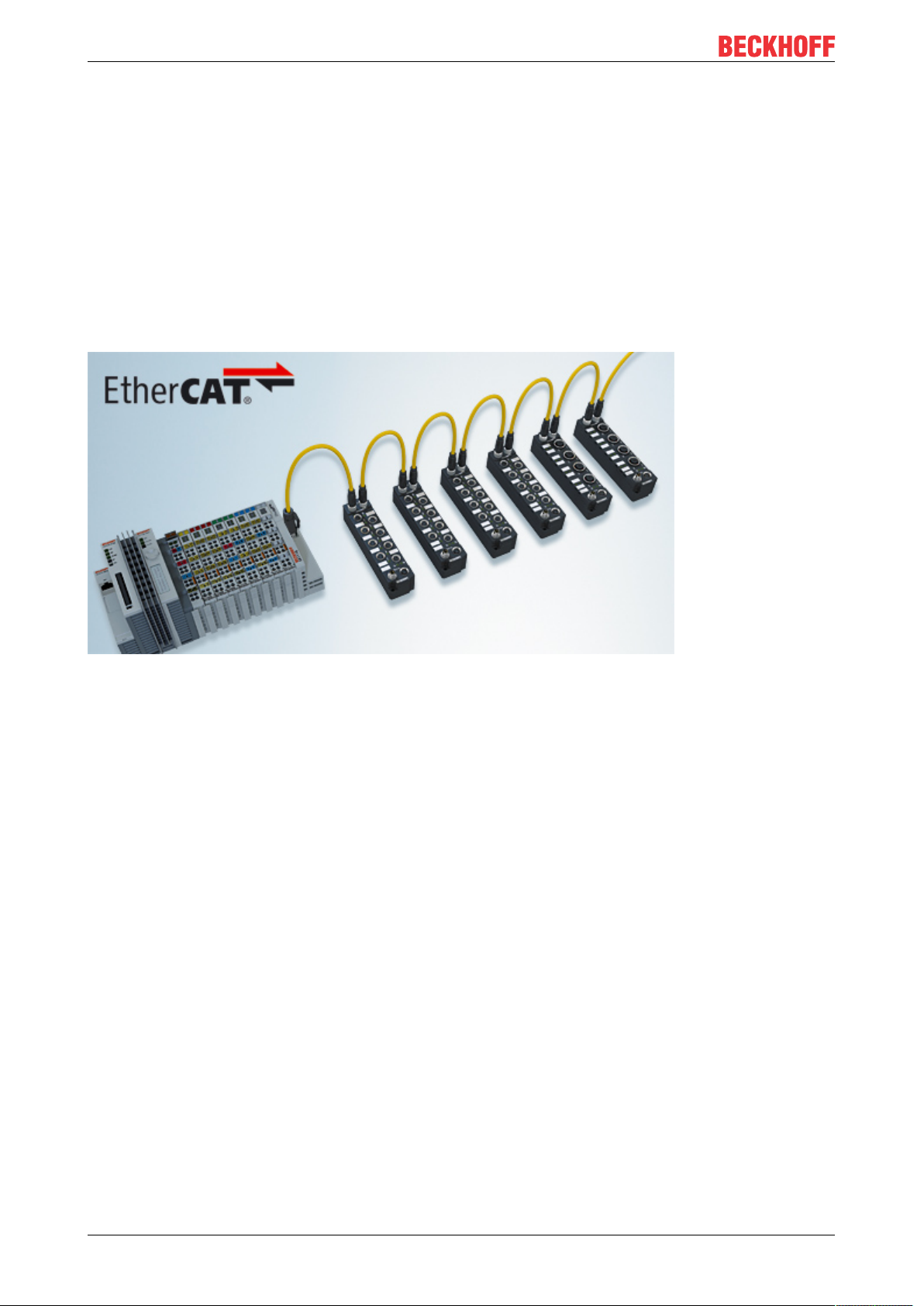
Fig.1: EtherCAT Box Modules within an EtherCAT network
The robust design of the EtherCAT Box modules enables them to be used directly at the machine. Control
cabinets and terminal boxes are now no longer required. The modules are fully sealed and therefore ideally
prepared for wet, dirty or dusty conditions.
Pre-assembled cables significantly simplify EtherCAT and signal wiring. Very few wiring errors are made, so
that commissioning is optimized. In addition to pre-assembled EtherCAT, power and sensor cables, fieldconfigurable connectors and cables are available for maximum flexibility. Depending on the application, the
sensors and actuators are connected through M8 or M12connectors.
The EtherCAT modules cover the typical range of requirements for I/O signals with protection class IP67:
• digital inputs with different filters (3.0ms or 10μs)
• digital outputs with 0.5 or 2A output current
• analog inputs and outputs with 16bit resolution
• Thermocouple and RTD inputs
• Stepper motor modules
XFC (eXtreme Fast Control Technology) modules, including inputs with time stamp, are also available.
EP72118 Version: 1.0
Page 9

Fig.2: EtherCAT Box with M8 connections for sensors/actuators
Product overview
Fig.3: EtherCAT Box with M12 connections for sensors/actuators
Basic EtherCAT documentation
You will find a detailed description of the EtherCAT system in the Basic System Documentation for
EtherCAT, which is available for download from our website (www.beckhoff.com) under Downloads.
EtherCAT XML Device Description
You will find XML files (XML Device Description Files) for Beckhoff EtherCAT modules on our website (www.beckhoff.com) under Downloads, in the Configuration Files area.
EP7211 9Version: 1.0
Page 10
Product overview
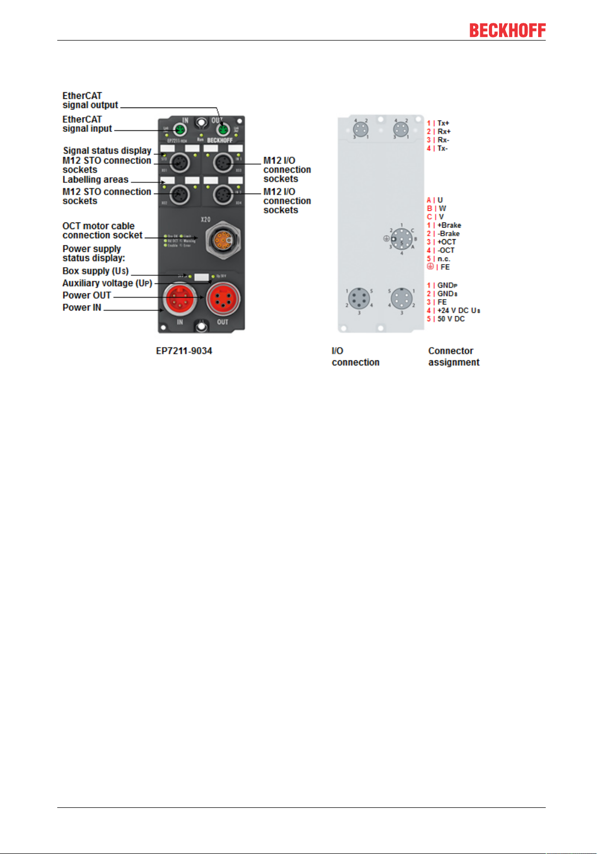
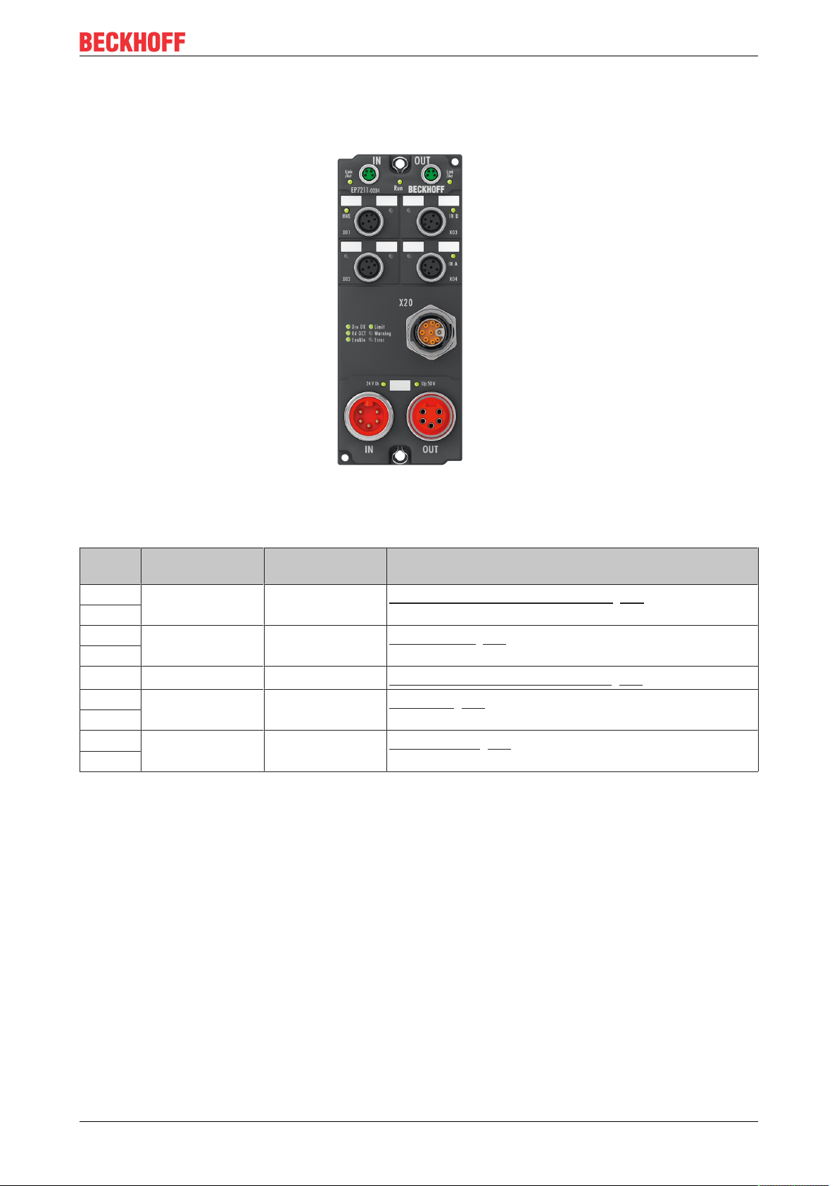
2.2 EP7211-x034 - Introduction
Fig.4: EP7211-9034
The EP7211-x034 EtherCAT Box is a single-channel servo drive for synchronous servomotors with OCT
feedback system.
It is intended for operation with motors from the AM81xx series. These motors have an electronic
identification plate. EP7211-x034 can read the electronic identification plate in order to set the motor
parameters in TwinCAT automatically.
The EP7211-9034 variant supports the "Safe Torque Off" (STO) function. This variant is non-reactive and
can be used in a safety application.
Process-side interfaces of EP7211-x034:
• Motor
• Motor brake
• OCT communication:
◦ Feedback
◦ Electronic identification plate readout
• 2 x touch probe
• Hardware Enable (EP7211-0034): digital input for activating the output stage
• Safe Torque Off (EP7211-9034)
The motor is connected via a hybrid cable. The hybrid cable contains the wires for the motor phases, the
brake and the OCT communication.
EP7211-x034 can be controlled via the MDP742 or alternatively the DS402 drive profile.
EP721110 Version: 1.0
Page 11

2.3 Technical data
Technical data EP7211-0034 EP7211-9034
Fieldbus
Fieldbus EtherCAT
Connection 2 x M8 socket (green)
Electrical isolation 500V (fieldbus / IO)
Distributed Clocks
Process image
Supply
Connection
Control voltage U
DC link supply voltage U
S
P
Supply of the module electronics from the control voltage U
Current consumption of the module
electronics
Current consumption from the
DC link supply voltage
Motor
Motor type Synchronous servomotor
Connection
Power rating P
Nominal output current I
Peak output current I
n
n
peak
Output frequency range 0..599Hz
PWM clock frequency 16kHz
Current controller frequency 32kHz
Speed controller frequency 16kHz
Drive profile [}61]
Motor brake
Output voltage 24VDC from the control voltage U
Output current max. 0.5A, short-circuit protected
Digital inputs
Interfaces 2 x touch probe
Yes
Dependent on the operation mode [}62]
Feed: 1 x 7/8" plug, 5-pin [}18]
Downstream connection: 1 x 7/8" socket, 5-pin [}18]
24VDC (-15% / +20%)
48VDC (8 - 50VDC), not protected against polarity reversal
S
typ. 120mA
typ. 50mA
1 x iTec socket, 9-pin, M23 [}22]
Hybrid connector for:
• 1 x motor
• 1 x feedback (OCT encoder)
• 1 x brake
max. 276W
4.5A
rms
9.0A
for 1s
rms
Alternatively:
• MDP 742 (default)
• CiA DS402
S
2 x touch probe
1 x Hardware Enable
1 x Safe Torque Off (STO)
Product overview
EP7211 11Version: 1.0
Page 12

Product overview
Technical data EP7211-0034 EP7211-9034
Environmental conditions
Permissible ambient temperature
during operation
Permissible ambient temperature
during storage
Vibration/ shock resistance conforms to EN60068-2-6/ EN60068-2-27
EMC immunity/emission conforms to EN61000-6-2/ EN61000-6-4
EMC category Category C3 (auxiliary filter required)
Protection class IP65, IP66, IP67 (conforms to EN 60529)
Mechanics
Dimensions 150mmx 60mmx 26.5mm (without plug connectors)
Weight approx.500g
Installation position variable
Approvals and conformity
Approvals CE, UL in preparation
-25°C ... +60°C
-40°C ... +85°C
Category C2, C1 in preparation (auxiliary filter required)
2.4 Scope of supply
Make sure that the following components are included in the scope of delivery:
• 1x EtherCAT Box EP7211-0034 / EP7211-9034
• 2x protective caps for EtherCAT socket (mounted)
• 1x protective cap for 7/8" socket (mounted)
• 10X labels, blank (1 strip of 10)
EP721112 Version: 1.0
Page 13
Product overview
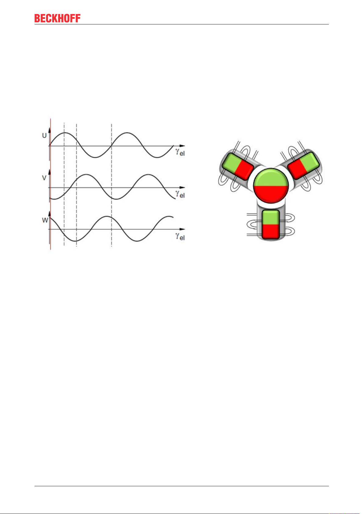
2.5 Technology
Servomotor
The servomotor is an electrical motor. Together with a servo drive the servomotor forms a drive. The
servomotor is operated in a closed control loop with position, torque or speed control.
EP7211-x034 supports control of permanent magnet synchronous motors. These consist of 3 coils which are
offset by 120° and a permanent magnet rotor.
Fig.5: Three synchronous motor coils, each offset by 120°
One Cable Technology (OCT)
In the servomotors from the AM8100-xF2 x series the feedback signals are transmitted directly via the power
supply cable, so that power and feedback system are combined in a single motor connection cable. With the
use of the One Cable technology, the information is sent reliably and without interference through a digital
interface. Since a cable and plug are omitted at both the motor and controller end, the component and
commissioning costs are reduced.
Thermal I²T motor model
The thermal I²T motor model represents the thermal behavior of the motor winding taking into account the
absolute thermal resistance Rth and the thermal capacity Cth of motor and the stator winding.
The model assumes that the motor reaches its maximum continuous operating temperature T
continuous operation with rated current I
. This temperature corresponds to 100% motor load. During
nom
nom
during
operation at rated current the motor model reaches a load of 63% after a time of τth=Rth∙Cth and slowly
reaches its continuous operating temperature.
If the motor is operated with a current that is greater than the rated current, the model reaches 100% load
more quickly.
If the load of the I²T model exceeds 100%, the requested set current is limited to the rated current, in order to
protect the motor winding thermally. The load reduces to a maximum of 100%. If the current falls below the
rated current, the load falls below 100% and the set current limitation is cancelled.
For a motor that has been cooled to ambient temperature, the time for reaching 100% load with a set current
that exceeds the rated current can be estimated with τth∙I
nom
²/I
actual
².
The actual load must be known for exact calculation of the time when the 100% load threshold is exceeded.
EP7211 13Version: 1.0
Page 14

Product overview
Fig.6: Limitation to the rated motor current
EP721114 Version: 1.0
Page 15

3 Mounting and cabling
150
60
141
Ø 4.5
3.1 Mounting
3.1.1 Dimensions
Mounting and cabling
Fig.7: Dimensions
All dimensions are given in millimeters.
Housing features
Housing material PA6 (polyamide)
Sealing compound polyurethane
Mounting two fastening holes Ø4.5mm for M4
Metal parts brass, nickel-plated
Contacts CuZn, gold-plated
Power feed through max. 16A at 40°C (according to IEC 60512-3)
Mounting position variable
Protection class IP65, IP66, IP67 (conforms to EN60529) when screwed together
Dimensions (HxWxD) approx. 150 x 60 x 26.5mm (without connectors)
EP7211 15Version: 1.0
Page 16

Mounting and cabling
FE
FE
3.1.2 Fixing
NOTE
Protect connectors against soiling!
Protection class IP67 can only be guaranteed if all cables and connectors are connected.
Protect the connections against soiling during mounting.
Mount the module with two M4 screws in the centrally located fastening holes.
The bolts must be longer than 15mm. The fastening holes in the modules have no thread.
Note when mounting that the overall height is increased further by the fieldbus connections. See chapter
Accessories.
3.1.3 Functional earth (FE)
All existing connections for the functional earth must be connected to earth:
• Fastening holes
• "FE" cores in the supply cables
Functional earth via the fastening holes
The fastening holes [}16] also serve as connections for the functional earth (FE).
Make sure that the box is earthed with low impedance via both fastening screws.
Fig.8: Functional earth via the fastening holes
Functional earth via the supply lines
The pins of the supply connectors [}18] marked with "FE" are directly connected to the functional earth
potential of the fastening holes.
Connect the functional earth of the "FE" cores in accordance with the following instructions:
• If the remote station is a device with a 7/8" connector: connect the devices with a pre-configured cable.
Possible types of preconfigured cables:
◦ Beckhoff ZK2030-1112-0xxx
◦ Beckhoff ZK2030-1114-0xxx
◦ Beckhoff ZK2030-1314-0xxx
• Otherwise: Earth the "FE" core with low impedance as near as possible to the remote station.
EP721116 Version: 1.0
Page 17
3.2 Cabling
X60 X61
X20
X04
X03
X02
X01
X40 X41
Mounting and cabling
Fig.9: Connector overview
Name Connector
type
X01 M12 0.6Nm
Tightening
torque
1)
Function
Hardware Enable / Safe Torque Off [}24]
X02
X03 M12 0.6Nm
1)
Touch Probe [}27]
X04
X20 iTec M23 -
X40 M8 0.4Nm
1)
Motor, brake and feedback system [}22]
EtherCAT [}20]
X41
X60 7/8" 1.5Nm
Power supply [}18]
X61
1)
Mount connectors on these plug connectors using a torque wrench, e.g. ZB8801 from Beckhoff.
EP7211 17Version: 1.0
Page 18

Mounting and cabling
1
2
3
4
5
IN
5
4
3
2
1
OUT
3.2.1 Power supply
3.2.1.1 Connection
Two 7/8" connectors at the low-end of the modules are used for feeding and routing the supply voltages:
• "IN" (male): left connector for feeding the supply voltages
• "OUT" (female): right connector for downstream connection
Fig.10: 7/8" connector pin assignment
NoteDefect possible through polarity reversal. The input for the DC link voltage Up is not protected
against polarity reversal. Ensure that the polarity is correct.
Pin Name Comment Core colors
1 GND
2 GND
P
S
GND to U
GND to U
P
S
Black
Blue
3 FE Functional earth Grey
4 +24 VDC U
5 +48 VDC U
1)
The core colors apply to cables of the type: Beckhoff ZK203x-xxxx.
S
P
Control voltage U
DC link voltage U
S
P
Brown
White
1)
EP721118 Version: 1.0
Page 19
Mounting and cabling
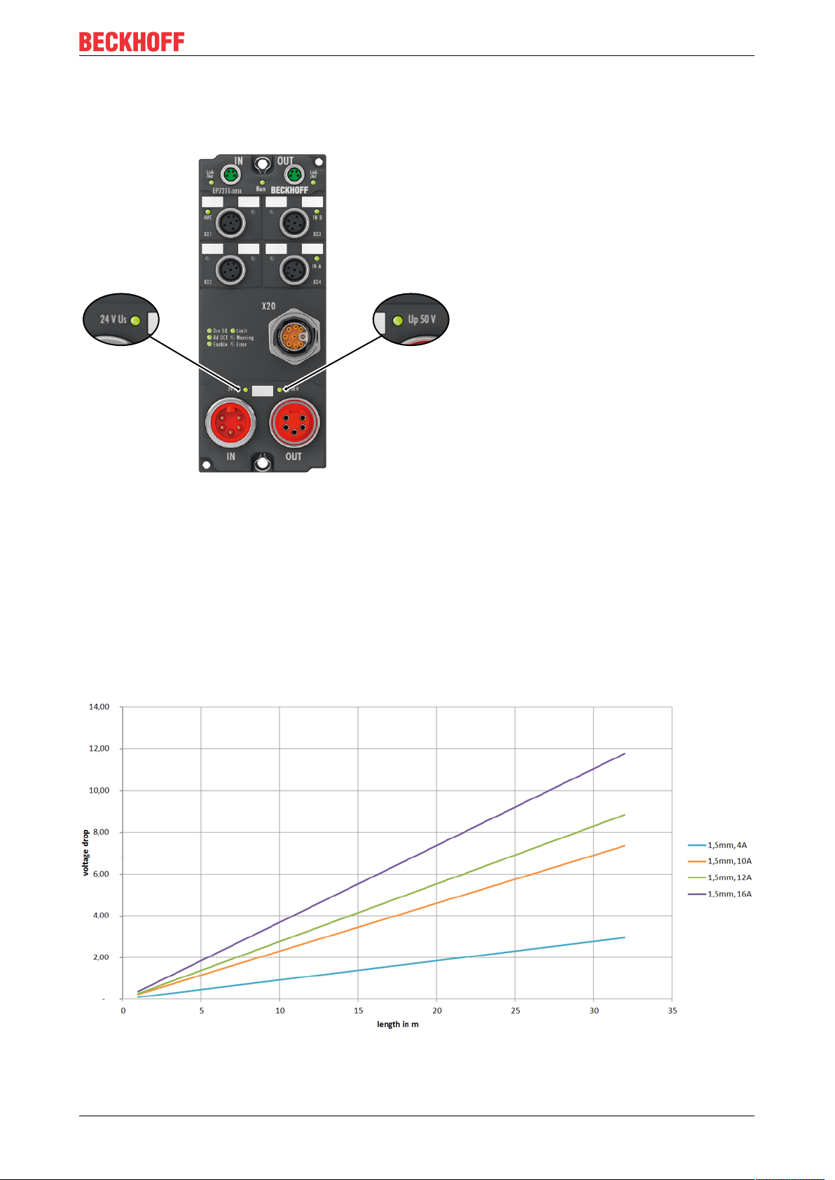
3.2.1.2 Status LEDs
The status of the supply voltages is signaled by two LEDs. A Status LED lights up green when the respective
supply voltage is present on the connector for the supply.
Fig.11: Power supply Status LEDs
3.2.1.3 Conductor losses
Take into account the voltage drop on the supply line when planning a system. Avoid the voltage drop being
so high that the supply voltage at the box lies below the minimum permissible value. See Technical data.
Variations in the voltage of the power supply unit must also be taken into account.
The following graph illustrates the dependence of the voltage drop on the core cross-section, current and
cable length:
Fig.12: Losses on the supply line
EP7211 19Version: 1.0
Page 20

Mounting and cabling
3.2.2 EtherCAT
3.2.2.1 Connection
EtherCAT Boxes (EPxxxx) have two green M8 sockets for the incoming and outgoing EtherCAT
connections.
Fig.13: EtherCAT connection
Fig.14: M8 socket pin assignment
Assignment
There are various different standards for the assignment and colors of connectors and cables for EtherCAT.
EtherCAT Plug connector Cable Standard
Signal M8 M12 RJ45
Tx + Pin 1 Pin 1 Pin 1 yellow
Tx - Pin 4 Pin 3 Pin 2 orange
Rx + Pin 2 Pin 2 Pin 3 white
Rx - Pin 3 Pin 4 Pin 6 blue
Shield Housing Shroud Shield Shield Shield
1
) colored markings according to EN 61918 in the four-pin RJ45 connector ZS1090-0003
2
) wire colors according to EN 61918
3
) wire colors
1
ZB9010, ZB9020,
ZB9030, ZB9032,
ZK1090-6292,
ZK1090-3xxx-xxxx
2
2
2
2
ZB9031 and old versions of ZB9030,
ZB9032,
ZK1090-3xxx-xxxx
orange/white
orange
blue/white
3
blue
3
3
3
TIA-568B
white/orange
orange
white/green
green
Assimilation of color coding for cable ZB9030, ZB9032 and ZK1090-3xxxx-xxxx (with
M8 connectors)
For unification, the prevalent cables ZB9030, ZB9032 and ZK1090-3xxx-xxxx were changed to the
colors of EN61918 (yellow, orange, white, blue). So different color coding exists. But the electrical
properties are absolutely identical.
EP721120 Version: 1.0
Page 21

3.2.2.2 Status LEDs
Mounting and cabling
Fig.15: EtherCAT Status LEDs
L/A (Link/Act)
A green LED labelled "L/A" or “Link/Act” is located next to each EtherCAT/EtherCATP socket. The LED
indicates the communication state of the respective socket:
LED Meaning
off no connection to the connected EtherCAT device
lit LINK: connection to the connected EtherCAT device
flashes ACT: communication with the connected EtherCAT device
Run
Each EtherCAT slave and each EtherCATP slave has a green LED labelled "Run". The LED signals the
status of the slave in the EtherCAT network:
LED Meaning
off Slave is in "Init" state
flashes uniformly Slave is in "Pre-Operational“ state
flashes sporadically Slave is in "Safe-Operational" state
lit Slave is in "Operational" state
A description of the EtherCAT slave states can be found under
https://infosys.beckhoff.com/content/1033/ethercatsystem/1036980875.html?id=8582353789396071752.
EP7211 21Version: 1.0
Page 22

Mounting and cabling
C
B
A
5
1
2
4
3
3.2.3 Motor, brake and feedback system
3.2.3.1 Connection
Fig.16: iTec socket pin assignment
Pin Name Comment Core colors
1 Brake + Motor brake + Red
2 Brake - Motor brake - Black
3 OCT + Data and supply for the OCT feedback system White
4 OCT - Data and supply for the OCT feedback system Blue
5 - A U Motor phase U Black
B W Motor phase W Grey
C V Motor phase V Brown
FE, shield Functional earth, cable shield green-yellow
1)
The core colors apply to the ZK470x-xxxx motor cables from Beckhoff.
1)
EP721122 Version: 1.0
Page 23

3.2.3.2 Status LEDs
Fig.17: Status LEDs of the motor connection
LED Displays
LED Display Meaning
Drv OK green
illuminated
Rd OCT flashing green The electronic identification plate is being read.
Enable green The driver stage is enabled.
Limit orange Limit reached (e.g. torque or speed limit).
Warning flashes Error while reading the electronic identification plate.
orange Warning. The "Warning" threshold value is exceeded.
The driver stage is ready for operation.
The LED is linked with bits 1 and 2 of the Status word1).
The LED is linked with bit 11 of the Status word1).
Possible reasons:
• Motor load (I²T) is higher than 100%
Mounting and cabling
• The motor output stage is not activated [}29]
• Maximum operating temperature exceeded
The LED is linked with bit 7 of the Status word1).
Error red Error. The “Error” threshold value is exceeded.
Possible reasons:
• Overcurrent
• STO triggered with active axis
• Voltage not available
• Feedback not connected
• Max. temperature (100 °C) exceeded
The LED is linked with bit 3 of the Status word1).
1)
Status word in the CoE directory:
• Device profile MDP742 [}92] (default)
• Device profile DS402 [}114]
EP7211 23Version: 1.0
Page 24

Mounting and cabling
1
2
3
4
5
3.2.4 Hardware Enable / Safe Torque Off
EP7211-0034 and EP7211-9034 differ from each other by the purpose of use of the digital input "Hardware
Enable" / "Safe Torque Off":
Hardware variant Designation of the digital input Purpose of use of the digital input
EP7211-0034 Hardware Enable (HWE)
EP7211-9034 Safe Torque Off (STO) Safe Torque Off
Safe Torque Off (STO)
Refer to the Application Guide TwinSAFE if you wish to use the EP7211-9034 in a safety application: an
application example with "Safe Torque Off" for EL72x1-9014 is described in chapter 2.27. EP7211-9034 can
be used instead of EL72x1-9014 in this application example if you observe the following note:
WARNING
Wiring of the STO
The wiring between EL2904 and the STO input of EP7211-9034 must be done with a separate sheathed
cable in order to be able to assume a fault exclusion for the cross-circuit or external power supply of the
wiring between EL2904 and EP7211-9034. Alternatively, the wiring is to be protected individually by an
earth connection.
The evaluation of this wiring and the evaluation of whether the fault exclusion is permissible must be done
by the machine manufacturer or user.
Activation of the motor output stage
[}29]
3.2.4.1 Connection
Connect the "Hardware Enable" / "Safe Torque Off" signal to the X01 or alternatively the X02 socket. The
X01 and X02 sockets have the same configuration and are bridged 1:1 inside the box.
Fig.18: M12 socket pin assignment
Pin Signal Core colors
1 n.c. Brown
2 n.c. White
3 n.c. Blue
4 EP7211-0034: Hardware Enable
EP7211-9034: Safe Torque Off
5 FE (Functional earth) Grey
1)
The core colors apply to cables of the types ZK2000-5xxx, ZK2000-6xxx and ZK2000-7xxx from Beckhoff.
Black
1)
EP721124 Version: 1.0
Page 25
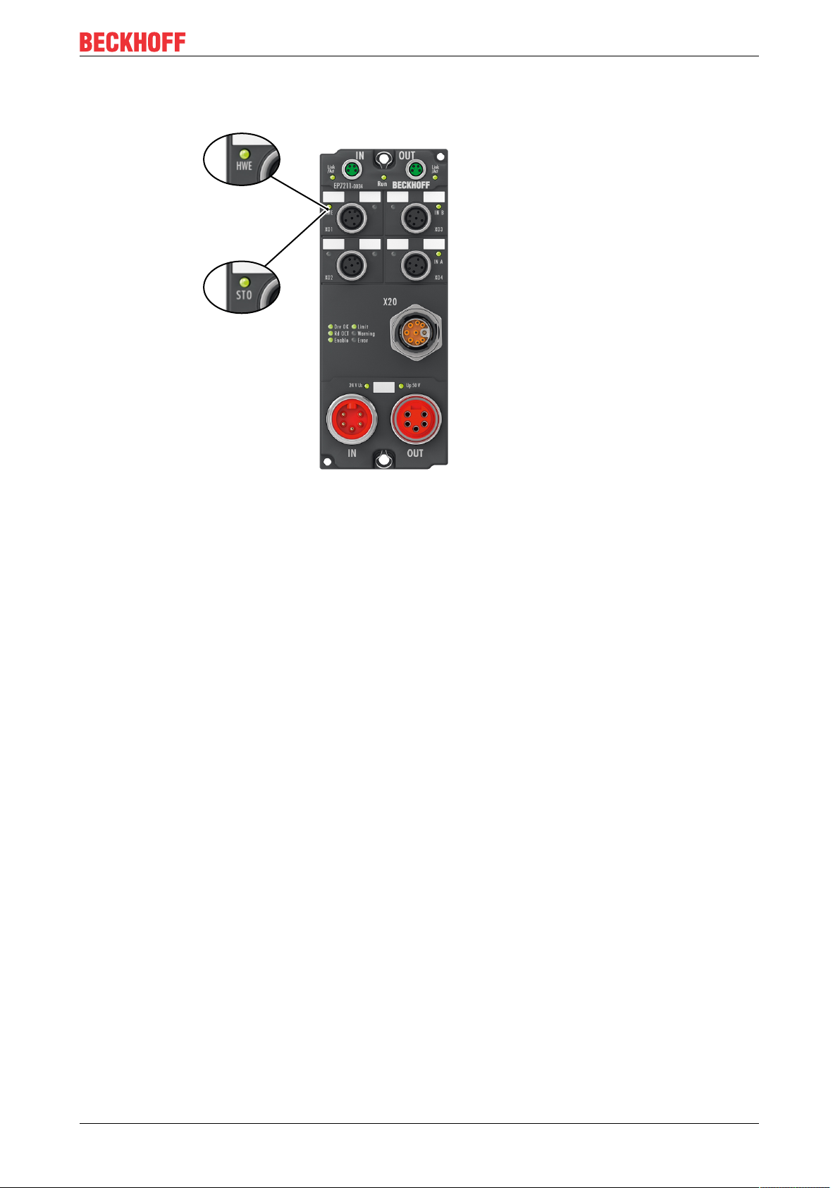
3.2.4.2 Status LEDs
EP7211-9034
EP7211-0034
Mounting and cabling
Fig.19: Status LEDs for HWE/STO
EP7211-0034
The green LED with the name "HWE" (Hardware Enable) lights when a high level is present on the
corresponding pin of X01 or X02.
→ The motor output stage is activated.
EP7211-9034
The green LED with the name "STO" (Safe Torque Off) lights when a high level is present on the
corresponding pin of X01 or X02.
→ The motor output stage is activated.
EP7211 25Version: 1.0
Page 26
Mounting and cabling
EP7211
HWE /
STO
EP7211
Box 1 Box 2
...
Cable
Cable
Cable
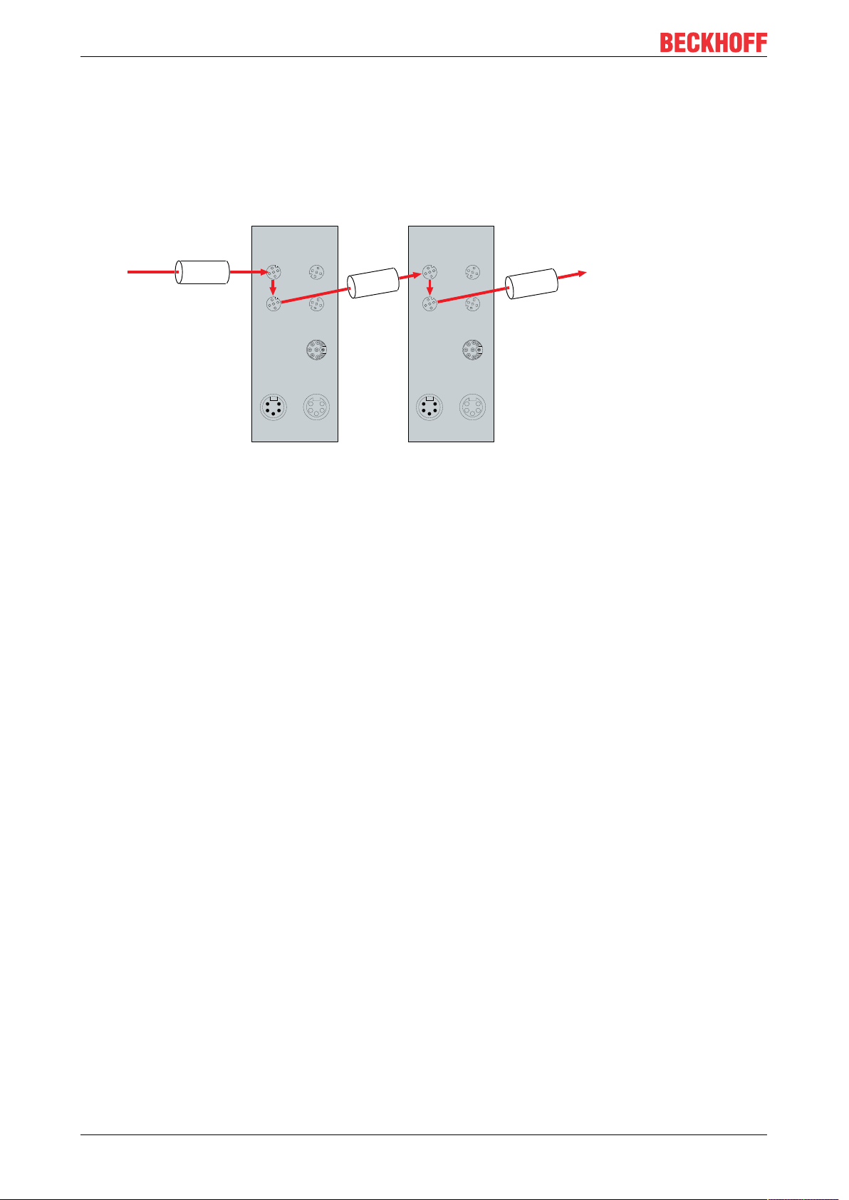
3.2.4.3 Cabling
The X01 and X02 sockets have the same configuration and are bridged 1:1 inside the box. This makes it
possible to forward the signal for "Hardware Enable" / "Safe Torque Off" from one box to the next.
Sample:
Fig.20: Sample: forwarded HWE/STO signal
EP721126 Version: 1.0
Page 27
Mounting and cabling
1
2
3
4
5
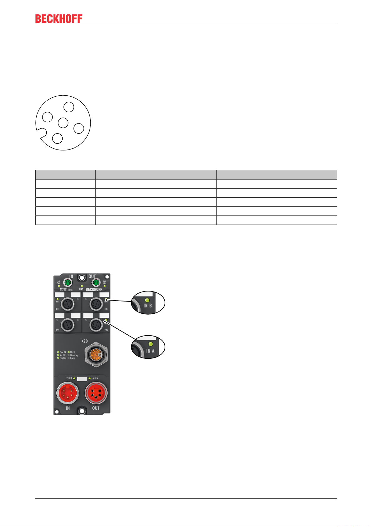
3.2.5 Touch Probe
3.2.5.1 Connection
Connect touch probes to the sockets X03 and X04. The X03 and X04 sockets have the same configuration
and are bridged 1:1 inside the box.
Fig.21: M12 socket pin assignment
Pin Signal Core colors
1 US: +24V
DC
Brown
1)
2 IN B = TP2 White
3 GND
S
Blue
4 IN A = TP1 Black
5 n.c. Grey
1)
The core colors apply to cables of the types ZK2000-5xxx, ZK2000-6xxx and ZK2000-7xxx from Beckhoff.
3.2.5.2 Status LEDs
Fig.22: Touch probe Status LEDs
The green LEDs with the names "IN A" and "IN B" light when a high level is present on the corresponding
pins of X03 or X04:
• IN A = TP1
• IN B = TP2
EP7211 27Version: 1.0
Page 28

Mounting and cabling
X03
X04
Cable
X03
X04
Cable
Cable
3.2.5.3 Cabling
The X03 and X04 sockets have the same configuration and are bridged 1:1 inside the box. This enables the
touch probes to be wired in two ways:
• One common cable (connection to X03 or X04)
• One cable per touch probe (connection to X03 and X04)
EP721128 Version: 1.0
Page 29

Commissioning
4 Commissioning
4.1 Activate motor output stage
Activate the motor output stage by applying a high level to the digital input Hardware Enable / Safe Torque
Off [}24].
4.2 Configuration in TwinCAT
An EtherCAT Box must be configured in TwinCAT so that its functions can be used in a PLC program.
The following link will take you to a quick start guide describing the configuration of an EtherCAT Box in
TwinCAT:
https://infosys.beckhoff.com/content/1033/epioconfiguration/index.html?id=6991403443235907429
EP7211 29Version: 1.0
Page 30
Commissioning
4.3 Start-up and parameter configuration
4.3.1 Integration into the NC configuration
(Master: TwinCAT 2.11 R3)
Installation of the latest XML device description
Please ensure that you have installed the corresponding latest XML device description in TwinCAT.
This can be downloaded from the Beckhoff Website and installed according to the installation in-
structions.
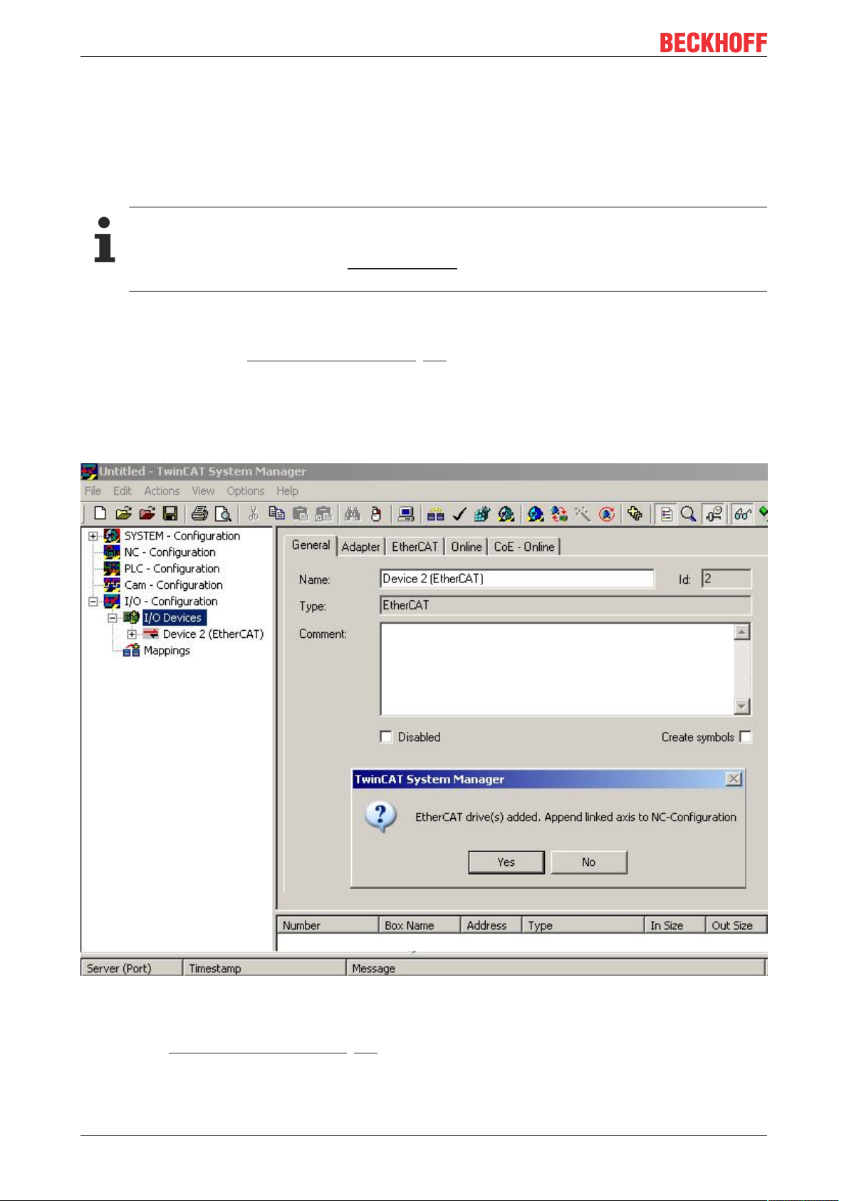
Integration into the NC can be accomplished as follows:
• The box must already have been added manually under I/O devices or have been scanned in by the
system (see section Configuration in TwinCAT [}29]).
Adding an axis automatically
• TwinCAT detects the new axes automatically once the IO modules have been successfully scanned.
The user is asked whether the detected axes should be added
automatically (see Fig. Axis detected). If this is confirmed, all axes are automatically liked to the NC.
Fig.23: Axis detected
• Several parameters have to be set before the motor can be started up. The values can be found in the
chapter Settings in the CoE register [}39].
Set these parameters before continuing with the motor commissioning.
EP721130 Version: 1.0
Page 31

Commissioning
Adding an axis manually
• First add a new task. Right-click on NC configuration and select "Append Task..." (see Fig. Adding a
new task).
• Rename the task if required and confirm with OK.
Fig.24: Adding a new task
• Right-click on Axes, then add a new axis (see Fig. Adding a new axis).
Fig.25: Adding a new axis
• Select Continuous Axis type and confirm with OK (see Fig. Selecting and confirming the axis type).
EP7211 31Version: 1.0
Page 32

Commissioning
Fig.26: Selecting and confirming the axis type
• Left-click your axis to select it. On the Settings tab, select "Link To..." (see Fig. Linking the axis with the
box).
Fig.27: Linking the axis with the box
• Select the appropriate box (CANopen DS402, EtherCAT CoE) and confirm with "OK".
Fig.28: Selection of the correct box
• All main links between the NC configuration and the box are set automatically (see Fig. Automatic
linking of all main variables)
EP721132 Version: 1.0
Page 33

Commissioning
Fig.29: Automatic linking of all main variables
• Several parameters have to be set before the motor can be started up. The values can be found in the
chapters Settings in the CoE register [}39] and NC settings [}42].
Set these parameters before continuing with the motor commissioning.
EP7211 33Version: 1.0
Page 34

Commissioning
4.3.2 Settings with the Drive Manager
(Master TwinCAT 2.11 R3)
The data given here serve as an example for a servomotor type AM8131-0F20-0000 from Beckhoff
Automation. For other motors the values may vary, depending on the application.
Table of contents
Start-up with the Drive Manager [}34]
Setting further parameters with the Drive Manager [}38]
Integral velocity controller component Tn [}38]
Proportional velocity controller component Kp
The TwinCAT Drive Manager is available for download in the AX5000 download package.
The TwinCAT Drive Manager for parameterizing an EL7211 is integrated in the System Manager, so that no
separate configuration tool is required. Once an EP7211 has been detected or entered, the TwinCAT Drive
Manager is available on the "Configuration" tab.
The following points are intended to enable you to start up the EP7211 quickly. More detailed information on
the Drive Manager can be found in the corresponding documentation "AX5000 Introduction in the
TCDrivemanager"
Start-up with the Drive Manager
• The box must already have been added manually under I/O devices or have been scanned in by the
system (see chapter Configuration in TwinCAT [}29])
• The box must already have been integrated in the NC (see chapter Integration into the NC
configuration [}30])
• Select the Drive Manager tab of the EP7211.
• Select the connected voltage under Power Management.
Fig.30: Selecting the connected voltage
• You can subsequently scan or select the connected motor under Channel A > Configuration > Motor
and Feedback. If you decide to use automatic scanning, click on Scan motor and feedback. The
electronic identification plate of the AM81xx-x2xx motor will then be read automatically. To do this it is
necessary for automatic scanning of the motor to be activated in the box (Index 0x8008 [}85], MDP
or Index 0x2018 [}113], DS402)
EP721134 Version: 1.0
Page 35

Commissioning
Fig.31: Automatic scanning of the connected motor
• If you decide to manually input the connected motor, please click on Select Motor.
Fig.32: Selecting the connected motor
• Select the suitable motor in the selection window and confirm with Ok.
EP7211 35Version: 1.0
Page 36

Commissioning
Fig.33: List of available motors
• Confirm the next dialog box with OK. All required parameters are automatically entered in the NC, and
the scaling factor is calculated. If this is not confirmed, these settings have to be entered manually. See
section NC settings [}42].
Fig.34: Confirmation of the automatic NC settings parameters
• The scaling can be determined under Scalings and NC Parameters. A motor revolution is defined as
360° as an example. All required parameters are adjusted automatically. The setting only becomes
active once the configuration is activated.
EP721136 Version: 1.0
Page 37

Commissioning
Fig.35: Adapting the scaling
All main parameters for the commissioning the motor are now set. The motor can now be commissioned with
the NC, for example. A brief description can be found in section "Commissioning the motor with the NC". Or
the NC can be addressed from the PLC. A sample program has been added in the documentation for this
also.
Some parameters can be adjusted manually for your particular application.
EP7211 37Version: 1.0
Page 38

Commissioning
Setting further parameters with the Drive Manager
The values specified here are exemplary, although in most cases they have led to excellent results.
Depending on the application, other values may yield better results.
These values can be changed during operation. Click on Download to apply the values.
Integral velocity controller component Tn
• Reduce the value, until the motor starts to oscillate slightly. Then increase the value by 10%.
Fig.36: Adapting Tn
Proportional velocity controller component Kp
• Increase the value, until the motor starts to oscillate slightly. Then reduce the value to 80%.
Fig.37: Adapting Kp
EP721138 Version: 1.0
Page 39

Commissioning
4.3.3 Settings in the CoE register
(Master TwinCAT 2.11 R3)
The data given here serve as an example for a servomotor type AM8131-0F20-0001 from Beckhoff
Automation. For other motors the values may vary, depending on the application.
Table of contents
Settings in the CoE register [}39]
Settings in the CoE register [}41]
Setting further parameters [}41]
Settings in the CoE register [}41]
Torque limitation [}41]
Settings in the CoE register [}41]
Settings in the CoE register [}41]
Inserting the motor XML file
Downloading the motor XML files
The motor XML files are available for download from the Beckhoff website.
To facilitate commissioning of the EP7211, motor XML files have been created for the servomotors that are
supported by the EP7211. The XML files can be read in the System Manager.
All CoE parameters and DS402 parameters are then set as required.
• To read the motor XML file, select the EP7211 and open the Startup tab. Right-click in the empty field
and select Import from XML...(see Fig. Importing the motor XML file).
Fig.38: Importing the motor XML file
• Select the motor XML file that matches the connected motor (see Fig. Selecting the correct motor XML
file)
EP7211 39Version: 1.0
Page 40

Commissioning
Fig.39: Selecting the correct motor XML file
• All required parameters are then set, and the motor can be put into operation (see Fig. CoE
parameters of the motor XML file).
Fig.40: CoE parameters of the motor XML file
Startup list
Any further application-specific settings should also be implemented in the Startup list. Otherwise
the modified settings will be overwritten next time the box starts up.
EP721140 Version: 1.0
Page 41

Commissioning
Adaptation of current and voltage
NOTE
The motor may overheat!
In order to prevent overheating of the connected motor, it is important to adjust the output voltage of the
box to the actually connected voltage.
This requires the index 0x8010:19 [}86] (0x2002:19 [}108], DS402 profile) "Nominal DC Link Voltage" of
the connected voltage to be set accordingly
Setting further parameters
Single-turn bits (MDP742: Index 0x8000:12 [}84] / DS402: Index 0x2010:12 [}112])/
Multi-turn bits (MDP742: Index 0x8000:13 [}84] / DS402: Index 0x2010:13 [}112])
Here the user can specify how many single-turn and multi-turn bits the box should display. A total of 32bits
are available. These 32bits can be subdivided as required.
The standard setting is 20 single-turn bits and 12 multi-turn bits.
Single-turn bits: number of bits relating to the resolution of one rotor rotation.
Multiturn bits: after a rotor rotation the multi-turn bits are incremented by one.
The motor may overheat!
If the number of single-turn bits is changed, the scaling factor [}44] in the NC has to be adjusted.
Fig.41: Multi-turn / single-turn bits
Torque limitation (MDP742: Index 0x7010:0B [}94] / DS402: Index 0x6072:0 [}116])
Limits the current / torque to this value. The value is specified in 1000th of the rated current.
Integral velocity controller component Tn (MDP742: Index 0x8010:14 [}86] / DS402: Index
0x2002:14 [}108])
The values specified here are exemplary, although in most cases they have led to excellent results.
Depending on the application, other values may yield better results.
• Reduce the value, until the motor starts to oscillate slightly. Then increase the value by 10%.
Proportional velocity controller component Kp (MDP742: Index 0x8010:15 [}86] / DS402: Index
0x2002:15 [}108])
The values specified here are exemplary, although in most cases they have led to excellent results.
Depending on the application, other values may yield better results.
EP7211 41Version: 1.0
Page 42

Commissioning
• Increase the value, until the motor starts to oscillate slightly. Then reduce the value to 80%.
4.3.4 NC settings
(Master TwinCAT 2.11 R3)
The data given here serve as an example for a servomotor type AM8122-0F20-0000 from Beckhoff
Automation. For other motors the values may vary, depending on the application.
Table of contents
Definition of the unit [}42]
Selecting the maximum velocity [}43]
Dead time compensation [}43]
NC settings [}44]
NC settings [}44]
Calculation of the scaling factor [}45]
Scaling output [}45]
NC settings [}45]
Commissioning the motor with the NC
Several important parameters are required for the commissioning with the NC. These should be set as
follows before commissioning. A fundamental factor for setting the following parameters is the unit in which
the NC is set to operate. For the following parameters it was assumed that one revolution corresponds to
360°.
Definition of the unit
The unit can be defined in the Settings tab for the axis.
Fig.42: Definition of the unit
EP721142 Version: 1.0
Page 43

Commissioning
Selecting the maximum velocity
The maximum permitted velocity is calculated based on the maximum motor speed (name plate) and the
distance, in this case in relation to 360° per second.
Fig.43: Adjusting the reference velocity
The reference velocity matches the maximum permitted velocity.
Below that separate values for the maximum and minimum velocity for manual NC mode can be set.
Dead time compensation
The dead time compensation can be adjusted on the Time Compensation tab of Axis1_ENC.
It should theoretically be 3 cycles of the NC cycle time, although in practice 4 cycles are preferable.
Therefore, the settings of the parameters Time Compensation Mode Encoder should be ‚ON (with velocity) )‘
and Encoder Delay in Cycles ‘4’.
Fig.44: Dead time compensation parameter
EP7211 43Version: 1.0
Page 44

Commissioning
Setting the encoder mask
The maximum values for the encoder mask can be set in the Parameter tab for the Axis1_ENC encoder
settings. EP7211 provides a maximum of 32bits for the encoder.
The parameter Encoder Mask (maximum encoder value) can be used to set the maximum number of
available bits. By default this is set to 0xFFFF FFFF, which corresponds to 32bits (20 single-turn bits and 12
multi-turn bits). The calculation is based on the following equation.
The parameter Encoder Sub Mask (absolute range maximum value) indicates how many bits of the
maximum encoder value are single-turn bits. The default setting is 20 (and therefore 12 multi-turn bits). The
calculation is based on the following equation.
Further calculation example with 13 single-turn bits and 8 multi-turn bits.
Fig.45: Setting the encoder mask
Scaling factor
The scaling factor can be changed by selecting "Axis 1_Enc" and tab Parameter in the NC (see Setting the
Scaling Factor). The value can be calculated with the formulas specified below. The calculation is based on
the assumption that one revolution corresponds to 360°.
The number of single-turn bits is taken into account in the calculation of the scaling factor. As indicated
above, the default setting for EP7211 is 20 single-turn bits. This value is also used for calculating the scaling
factor. If the single-turn bit value is changed, the scaling factor must be adjusted.
EP721144 Version: 1.0
Page 45

Calculation of the scaling factor
Commissioning
Fig.46: Setting the Scaling Factor
Scaling output
Enter the value 32 in the Parameter tab for the drive settings under Output Scaling (Velocity).
Fig.47: Output scaling
Position lag monitoring
The position lag monitoring function checks whether the current position lag of an axis has exceeded the
limit value. The position lag is the difference between the set value (control value) and the actual value
reported back. If the box parameters are set inadequately, the position lag monitoring function may report an
error when the axis is moved. During commissioning it may therefore be advisable to increase the limits of
the Position lag monitoring slightly.
EP7211 45Version: 1.0
Page 46

Commissioning
NOTE
Damage to equipment, machines and peripheral components possible!
Setting the position lag monitoring parameters too high may result in damage to equipment, machines and
peripheral components.
Fig.48: Lag monitoring
Commissioning the motor with the NC
• Once the parameters are set, the motor is basically ready for operation. Individual further parameters
have to be adapted to the respective application.
• To commission the axis, activate the configuration (Ctrl+Shift+F4), select the axis, select tab Online
and enable the axis under Set.
• Set all tick marks and set Override to 100% (see Fig. Enabling an axis). The axis can then be moved.
EP721146 Version: 1.0
Page 47

Commissioning
Fig.49: Enabling an axis
You can now move the axis with the function keys F1, F2 (Backward) or F3, F4 (Forward).
You can adjust the Kv factor in order to approach a suitable factor. Set the value to 0 initially in order to set
the correct reference velocity. For calculating the reference velocity please refer to section "Selecting the
maximum velocity [}43]". The calculation provides a relatively precise value, although the value may have to
be corrected slightly. To this end move the motor with a Kv factor of 0 until the actual velocity matches the
setpoint velocity.
Alternatively you can control the axis via the Functions tab. An example is provided below.
• Select as Reversing Sequence as the start type.
• Enter the required Target Position2, e.g. 12000°.
• Enter the required Target Velocity, e.g. 12000°/s.
• Enter the required Target Position1, e.g. 0°.
• Enter the required Idle Time, e.g. 2 s.
• Select Start.
EP7211 47Version: 1.0
Page 48

Commissioning
Fig.50: Reversing Sequence
The motor now turns to position 2, remains there for 2 seconds and returns to position 1. This is repeated
until Stop is pressed.
4.3.5 Commissioning without NC, status word/control word
(Master: TwinCAT 2.11 R3)
In principle, the operating modes CST, CSTCA, CSV and CSP can be used without TwinCAT NC.
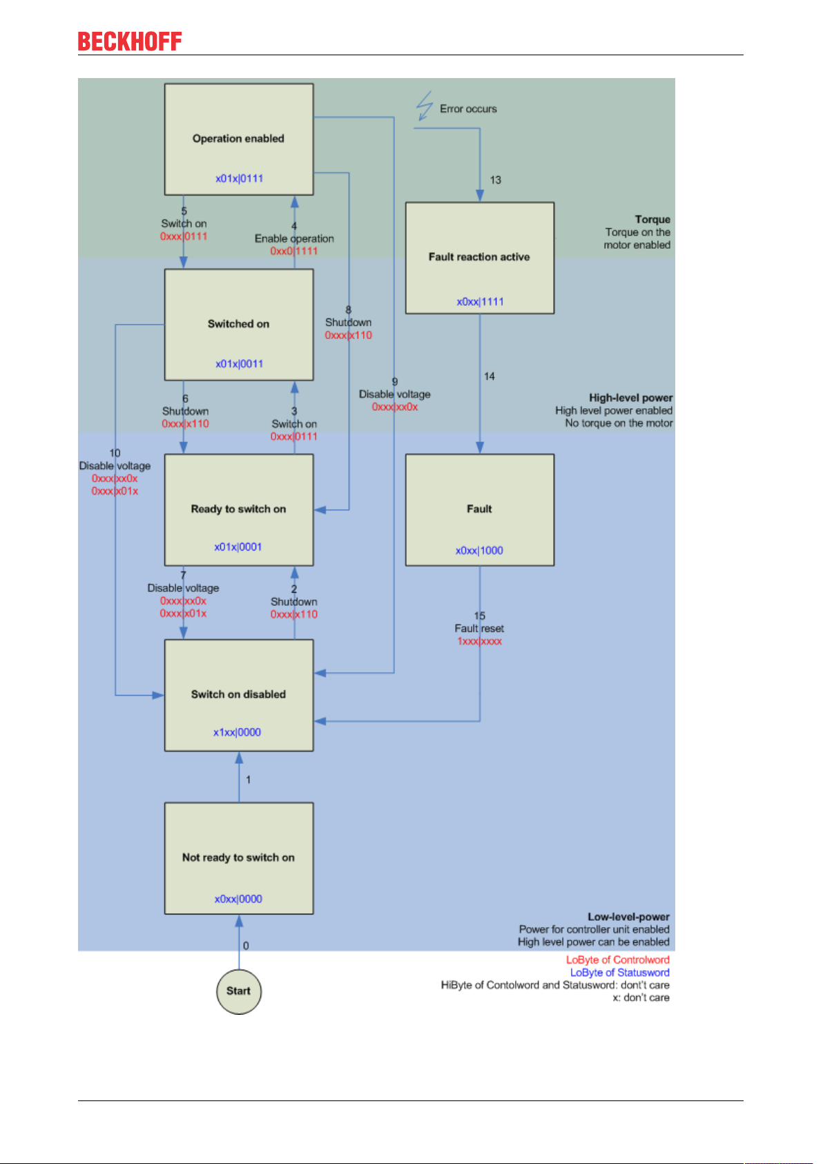
Output stage enabled via control word
The output stage has to be enabled for each operation mode. To this end enter the following values in the
specified order via the PLC control word (MDP742 [}94] / DS402 [}114]) (see Fig. DS402 State Machine).
The respective status messages are output in the status word (MDP742 [}92] / DS402 [}114]).
0
hex
80
(Fault reset)
hex
6
(Shutdown)
hex
7
(Switch on)
hex
F
(Enable operation)
hex
EP721148 Version: 1.0
Page 49
Commissioning
Fig.51: DS402 State Machine
EP7211 49Version: 1.0
Page 50

Commissioning
CST - cyclic synchronous torque
Select Cyclic synchronous torque mode in index 0x7010:03 [}94] Modes of operation (MDP) or 0x6060:0
[}115] Modes of operation (DS402). In the respective process data, the Predefined PDO Assignment: 'Cyclic
synchronous torque mode (CST)' should also be selected (see Process data MDP 742 [}76] or DS402
process data [}80]). The configuration then has to be reloaded in order to activate the selection.
Index 0x6010:03 [}92] Modes of operation display (MDP) or index 0x6061:0 [}115] Modes of operation
display (DS402) can be used to check the actual mode of the box.
Via the PLC a defined torque can be defined in the variable Target torque as a basis for the box control. The
torque is specified in 1000th of the rated current. A value of 1000
, for example, corresponds to the set
dec
index 0x8011:12 [}89] Rated current (MDP) or index 0x6075:0 [}116] Motor rated current (DS402). The
value 1
corresponds to one 1000th of the rated current.
dec
CSTCA - cyclic synchronous torque with commutation angle
Select Cyclic synchronous torque mode with commutation angle in index 0x7010:03 [}94] Modes of
operation (MDP) or index 0x6060:0 [}115] Modes of operation (DS402). In the respective process data, the
Predefined PDO Assignment: 'Cyclic synchronous torque mode with commutation angle mode (CSTCA)'
should also be selected (see Process data MDP 742 [}76] or DS402 process data [}80]). The configuration
then has to be reloaded in order to activate the selection.
Index 0x6010:03 [}92] Modes of operation display (MDP) or index 0x6061:0 [}115] Modes of operation
display (DS402) can be used to check the actual mode of the box.
Via the PLC a defined torque can be set in the Target torque variable as a basis for the box control and the
angle to be maintained with the set torque can be specified in the Commutation angle variable. The torque is
specified in 1000th of the rated current. A value of 1000
0x8011:12 [}89] Rated current (MDP) or index 0x6075:0 [}116] Motor rated current (DS402). The value 1
, for example, corresponds to the set index
dec
dec
corresponds to one 1000th of the rated current.
The angle value must be converted, 65536
corresponds to 360°.
dec
CSV - cyclic synchronous velocity
Select Cyclic synchronous velocity in index 0x7010:03 [}94] Modes of operation (MDP) or index 0x6060:0
[}115] Modes of operation (DS402). In the respective process data, the Predefined PDO Assignment: 'Cyclic
synchronous velocity mode (CSV)' should also be selected (see Process data MDP 742 [}76] or DS402
process data [}80]). The configuration then has to be reloaded in order to activate the selection.
Index 0x6010:03 [}92] Modes of operation display (MDP) or index 0x6061:0 [}115] Modes of operation
display (DS402) can be used to check the actual mode of the box.
Via the PLC a defined speed can be set in the variable Target velocity 0x7010:06 [}94] (MDP) or 0x60FF:0
[}118] (DS402) as a basis for the box control. The constant value Velocity encoder resolution in CoE object
0x9010:14 [}97] (MDP) or 0x6090:0 [}117] (DS402) corresponds to 1 revolution per second. If this value is
entered under Target velocity, the motor speed is 1 rpm. The velocity can be increased by entering a
suitable multiple of the Velocity encoder resolution value under Target velocity.
CSP - cyclic synchronous position
Select Cyclic synchronous position in index 0x7010:03 [}94] Modes of operation (MDP) or index 0x6060:0
[}115] Modes of operation (DS402).
In the respective process data, the Predefined PDO Assignment: 'Cyclic synchronous position mode (CSP)'
should also be selected (see Process data MDP 742 [}76] or DS402 process data [}80]). The configuration
then has to be reloaded in order to activate the selection.
Index 0x6010:03 [}92] Modes of operation display (MDP) or index 0x6061:0 [}115] Modes of operation
display (DS402) can be used to check the actual mode of the box.
Via the PLC a defined position can be set in the variable Target position 0x7010:05 [}94] (MDP) or
0x607A:0 [}116] (DS402) to which the motor is to drive. The calculated scaling factor is taken as the basis
for the calculation of the position. The value entered in the Target position variable must be multiplied by the
calculated scaling factor.
EP721150 Version: 1.0
Page 51

Commissioning
4.3.6 Settings for the automatic configuration
(Master TwinCAT 2.11 R3)
The EP7211 offers the option of automatically configuring the connected motor from the AM81xx series. The
electronic identification plate integrated in the motor is read and the necessary parameters of the box are
adapted accordingly.
The automatic configuration is switched off on delivery. The user has the possibility to adapt the automatic
configuration according to the flow chart shown below (see fig. Flow chart for the automatic configuration).
Overwriting of the parameters during automatic configuration
The parameters manually changed by the user in the parameter list of the automatic configuration
are automatically overwritten at the next start-up if automatic configuration is switched on.
• The automatic configuration can be switched on in the index 0x8001:01 [}85] (0x2018:01 [}113],
DS402 Profile) Enable autoconfig.
• In the index 0x8008:02 [}85] (0x2018:02 [}113], DS402 Profile) Reconfig identical motor, the user
can decide in the case of replacing an identical motor whether the box should automatically reconfigure the motor (setting = true) or whether the motor should be operated with the stored settings
(setting = false). The deactivation of this function can be advantageous, for example, if the user has
specially adjusted the motor to his application and does not want to lose these settings after replacing
the motor.
• In the index 0x8008:03 [}85] (0x2018:03 [}113], DS402 Profile) Reconfig non-identical motor , the
user can decide in the case of replacing a non-identical motor whether the box should automatically reconfigure the motor (setting = true) or whether the motor should be operated with the stored settings
(setting = false).
EP7211 51Version: 1.0
Page 52

Commissioning
Fig.52: Flow chart for the automatic configuration
EP721152 Version: 1.0
Page 53

Parameter list of the automatic configuration
The following parameters are affected by the automatic configuration.
Index (hex) Name Meaning
MDP 407 Profile DS402 Profile
8010:12 [}86] 2002:12 [}108]
8010:13 [}86] 2002:13 [}108]
8011:11 [}89] 2003:11 [}111]
8011:12 [}89] 2003:12 [}111]
8011:13 [}89] 2003:13 [}111]
8011:15 [}89] 2003:15 [}111]
8011:16 [}89] 2003:16 [}111]
8011:18 [}89] 2003:18 [}111]
8011:19 [}89] 2003:19 [}111]
8011:1B [}89] 2003:1B [}111]
8011:2B [}89] 2003:2B [}111]
8011:2C [}89] 2003:2C [}111]
8011:2D [}89] 2003:2D [}111]
8012:11 [}90] 2004:11 [}112]
8012:12 [}90] 2004:12 [}112]
8012:14 [}90] 2004:14 [}112]
Current loop integral time is calculated according to the symmetrical optimum
Current loop proportional gain is calculated according to the symmetrical optimum
Max. current is adopted directly from the electronic identification
plate of the connected motor
Rated current is adopted directly from the electronic identification
plate of the connected motor
Motor pole pairs is adopted directly from the electronic identification
plate of the connected motor
Commutation offset is always set to -90°
Torque constant is adopted directly from the electronic identification
plate of the connected motor
Rotor moment of inertia is adopted directly from the electronic identification
plate of the connected motor
Winding inductance is adopted directly from the electronic identification
plate of the connected motor
Motor speed limitation Calculation of the max. speed of the connected motor
Motor temperature warn level is adopted directly from the electronic identification
plate of the connected motor
Motor temperature error level is adopted directly from the electronic identification
plate of the connected motor
Motor thermal time constant is adopted directly from the electronic identification
plate of the connected motor
Release delay is adopted directly from the electronic identification
plate of the connected motor
Application delay is adopted directly from the electronic identification
plate of the connected motor
Brake moment of inertia is adopted directly from the electronic identification
plate of the connected motor
Commissioning
4.3.7 Configure end position monitoring
Software end position monitoring
The TwinCAT NC can be used to set software end position monitoring for EP7211 to ensure the safety of the
system. The axis does not move beyond the set position (maximum/minimum end position). End position
monitoring can be activated in the Parameter tab for the corresponding axis.
Fig.53: Pull-down menu for activating end position monitoring
EP7211 53Version: 1.0
Page 54

Commissioning
4.3.8 Homing
(Master TwinCAT 2.11 R3)
The data given here serve as an example for a servomotor type AM8131-0F20-0000 from Beckhoff
Automation. For other motors the values may vary, depending on the application.
Table of contents
Referencing [}54]
Function block "MC_Home" [}54]
Homing [}55]
Referencing
Referencing does not work via the online commissioning tab of the axis (see Fig. Online homing in the NC).
Fig.54: Online homing in the NC
Function block "MC_Home"
• Referencing must be done from the PLC. The function block MC_Home from the TC MC2 Lib is used
for this purpose.
• The following minimum configuration is required in MC_Home.
◦ HomingMode enables selection of mode to be used for referencing.
◦ Execute is used to initiate homing.
◦ bCalibrationCam, which has to be linked with your reference cam, is used to stop homing.
EP721154 Version: 1.0
Page 55

Commissioning
Fig.55: Configuration of the MC_Home block
• The following figure Extract from the functional description for MC_Home shows an extract from the
functional description of MC_Home. Full information can be found in the corresponding functional
description.
Fig.56: Extraction from the functional description for MC_Home
Reference modes
• EP7211 can be operated with the following NC reference modes (see Fig. Selection of the reference
modes in the NC).
• Default: Is suitable as a general setting and for most applications.
Once the motor reaches the reference cam, the direction is reversed. The declining cam signal causes
the motor to stop. The reference position is then set.
• Software Sync: The C track is modelled virtually.
EP7211 55Version: 1.0
Page 56

Commissioning
Fig.57: Selection of the reference modes in the NC
The velocity to be used for homing can also be set in the NC (Fig. Setting the reference velocity).
Fig.58: Setting the reference velocity
EP721156 Version: 1.0
Page 57

Commissioning
4.3.9 Touch Probe
(Master TwinCAT 2.11 R3)
Functional description
The touch probe function saves the current position of the motor when a signal edge is detected on a digital
input [}27].
The process data objects required for this can be activated on the Process data tab (see figs. Touch Probe
inputs and Touch Probe outputs).
EP7211 57Version: 1.0
Page 58

Commissioning
Fig.59: Touch Probe inputs
EP721158 Version: 1.0
Page 59

Commissioning
Fig.60: Touch Probe outputs
EP7211 59Version: 1.0
Page 60

Commissioning
Step-by-step
TP1 is used here as an example for the description of the function.
• TP1 Enable must be set to true in order to generally activate the Touch Probe function.
• Subsequently, you must decide whether the position is to be saved on a positive edge at input 1 (TP1
Enable pos edge = true), on a negative edge (TP1 Enable neg edge = true), or in both cases (both set
to ‘true’).
• With TP1 Continuous you can decide whether the position is to be saved only at the first event (TP1
Continuous = false) or whether this should take place at every event (TP1 Continuous = true).
For example, if TP1 Continous and TP1 Enablepos edge are set, the position is saved on each positive
edge at input 1 of the box.
If TP1 Enable neg edge is set and TP1 Continuous is not set, the position will only be saved on the first
negative edge at input 1 of the box. If you wish to repeat this procedure, you must first deactivate TP1
Enable and then activate it again. Then the position is saved again on the first negative edge.
• The TP1 Trigger mode has no function with the EP7211.
• The saved position of the positive edge can be read in the inputs of the process data under TP1 Pos
position, that of the negative edge under TP1 Neg position.
• The variables under Touch probe status are for the diagnosis.
• The Touch Probe inputs must be addressed with a 1-wire +24V signal.
EP721160 Version: 1.0
Page 61

Commissioning
4.4 Drive profiles
The EP7211 supports the MDP742 and DS402 drive profiles. Both drive profiles contain the same
parameters. The drive profiles define the presentation of the parameters in TwinCAT and the index, under
which the respective parameters are arranged in the object directory.
• The CoE objects in the MDP742 (Modular Device Profile) are allocated in the way that is common for
the Beckhoff IO modules.
• The DS402 drive profile is specified in IEC61800-7-200 (CiA402) and uses a different allocation of the
object directory structure.
The drive state machine in both profiles is based on the CiA402 State Machine [}48], which means the
functional behavior is identical.
The box is supplied ex factory with the MDP742 drive profile.
Changing the drive profile
You can change the drive profile by carrying out an EEPROM Update [}131]. Select the EEPROM
description on the basis of the following table.
Variant of the EP7211 Drive profile EEPROM description
EP7211-0034 MDP742 EP7211-0034
DS402 EP7211-0035
EP7211-9034 MDP742 EP7211-9034
DS402 EP7211-9035
The EEPROM description is at the same time the name of the IO module in the IO tree.
The CoE object description and the process data of the drive profiles are different. The motor XML files that
match the set profile must be used.
EP7211 61Version: 1.0
Page 62

Commissioning
4.5 Operation modes
4.5.1 Overview
Operation modes CST, CSTCA, CSV and CSP are supported. The operation mode is set in the CoE
directory in index 0x7010:03 [}94] Modes of operation (MDP) or index 0x6060:0 [}115] Modes of operation
(DS402). In the respective process data the user can additionally select the respective Predefined PDO
Assignment. All required variables are then in the process data.
CSV [}63] - cyclic synchronous velocity (velocity control)
The EP7211-x034 operates in the cyclic velocity interface in the CSV operation mode. A defined velocity can
be set via the Target velocity variable.
CST [}66] - cyclic synchronous torque (torque control)
The EP7211-x034 operates in the cyclic torque interface in the CST operation mode. A defined torque can
be set via the Target torque variable.
CSTCA [}69] - cyclic synchronous torque with commutation angle (torque control with commutation
angle)
This operation mode is also intended for use with the cyclic torque interface. In addition the user can specify
the commutation angle. The variable Commutation angle can be used to set an angle which is to be
maintained with a defined torque set in variable Target torque.
CSP [}72] - cyclic synchronous position (position control)
The EP7211-x034 operates in the cyclic position interface in the CSP operation mode. A defined position
can be set via the Target position variable.
For further information on the three operation modes described above please refer to section Commissioning
without NC [}48].
EP721162 Version: 1.0
Page 63

Commissioning
4.5.2 CSV
The EP7211-x034 operates in the cyclic velocity interface in the CSV operation mode. A defined velocity can
be set via the Target velocity variable.
Step-by-Step
• Add the box to the configuration as described in the chapter Configuration in TwinCAT [}29].
• Link the box with the NC as described in the chapter Integration into the NC configuration [}30].
• Import the motor XML file into the Startup directory as described in the chapter Settings in the CoE
[}39].
• Set the mode of operation in the CoE directory to Cyclic synchronous velocity mode (CSV), Fig.
Selection of the mode of operation.
Fig.61: Selection of the mode of operation
• Under Predefined PDO assignment, also select Cyclic synchronous velocity mode (CSV), Fig.
Selecting a predefined PDO assignment.
EP7211 63Version: 1.0
Page 64

Commissioning
Fig.62: Selecting a predefined PDO assignment
• Activate the configuration (Ctrl+Shift+F4)
• Run through the State Machine of the box. There are two ways to do this:
◦ If you use the TwinCAT NC.
The State Machine is run through automatically by the NC. You can enable the axis in the Online
tab of the axis.
Set all tick marks and set Override to 100% (see Fig. Set enables). The axis can then be moved.
EP721164 Version: 1.0
Page 65

Commissioning
Fig.63: Set enables
◦ If you don’t use the TwinCAT NC.
In this case you must run through the State Machine manually. To do this, follow the instructions in
the chapter Commissioning without the NC [}48].
• The cyclic variable Target velocity (Fig. Torque specification) can be used to specify a defined velocity.
The value in the index 0x9010:14 [}97] (0x6090 [}117], DS402) Velocity encoder resolution
corresponds to 1rpm.
Fig.64: Torque specification
EP7211 65Version: 1.0
Page 66

Commissioning
4.5.3 CST
The EP7211-x034 operates in the cyclic torque interface in the CST operation mode. A defined torque can
be set via the Target torque variable.
Step-by-Step
• Add the box to the configuration as described in the chapter Configuration in TwinCAT [}29].
• Link the box with the NC as described in the chapter Integration into the NC configuration [}30].
• Import the motor XML file into the Startup directory as described in the chapter Settings in the CoE
[}39].
• Set the mode of operation in the CoE directory to Cyclic synchronous torque mode (CST), Fig.
Selection of the mode of operation
Fig.65: Selection of the mode of operation
• Under Predefined PDO assignment, also select Cyclic synchronous torque mode (CST), Fig. Selecting
a predefined PDO assignment
EP721166 Version: 1.0
Page 67

Commissioning
Fig.66: Selecting a predefined PDO assignment
• Activate the configuration (Ctrl+Shift+F4)
• Run through the State Machine of the box. There are two ways to do this:
◦ If you use the TwinCAT NC.
The State Machine is run through automatically by the NC. You can enable the axis in the Online
tab of the axis.
Set all tick marks and set Override to 100% (see Fig. Set enabling). The axis can then be moved.
◦ If you don’t use the TwinCAT NC.
In this case you must run through the State Machine manually. To do this, follow the instructions in
the chapter Commissioning without the NC [}48].
EP7211 67Version: 1.0
Page 68

Commissioning
Fig.67: Set enabling
• The cyclic variable Target torque (Fig. Torque specification) can be used to specify a defined torque.
Fig.68: Torque specification
EP721168 Version: 1.0
Page 69

Commissioning
4.5.4 CSTCA
This operation mode is also intended for use with the cyclic torque interface. In addition the user can specify
the commutation angle. The variable Commutation angle can be used to set an angle which is to be
maintained with a defined torque set in variable Target torque.
Step-by-Step
• Add the box to the configuration as described in the chapter Configuration in TwinCAT [}29].
• Link the box with the NC as described in the chapter Integration into the NC configuration [}30].
• Import the motor XML file into the Startup directory as described in the chapter Settings in the CoE
[}39].
• Set the mode of operation in the CoE directory to Cyclic synchronous torque mode with commutation
angle (CSTCA), Fig. Selection of the mode of operation
Fig.69: Selection of the mode of operation
• Under Predefined PDO assignment, also select Cyclic synchronous torque mode with commutation
angle (CSTCA), Fig. Selecting a predefined PDO assignment.
EP7211 69Version: 1.0
Page 70

Commissioning
Fig.70: Selecting a predefined PDO assignment
• Activate the configuration (Ctrl+Shift+F4)
• Run through the State Machine of the box. There are two ways to do this:
◦ If you use the TwinCAT NC.
The State Machine is run through automatically by the NC. You can enable the axis in the Online
tab of the axis.
Set all tick marks and set Override to 100% (see Fig. Set enables). The axis can then be moved.
EP721170 Version: 1.0
Page 71

Commissioning
Fig.71: Set enables
◦ If you don’t use the TwinCAT NC.
In this case you must run through the State Machine manually. To do this, follow the instructions in
the chapter Commissioning without the NC [}48].
• You can specify a defined torque via the cyclic variable Target torque. The value is specified in 1000ths
of the rated current and the torque is calculated according to the following equation, where the rated
current refers to the value in the index 0x8011:12 [}89] rated current.
You can specify a defined angle via the cyclic variable Commutation angle. The value is specified in 360°/216.
Fig.72: Specification of torque and commutation angle
EP7211 71Version: 1.0
Page 72

Commissioning
4.5.5 CSP
The EP7211-x034 operates in the cyclic position interface in the CSP operation mode. A defined position
can be set via the Target position variable.
Minimum cycle time
The cycle time in CSP modus must be 2^n*125µs (where n = 1 to 8), i.e. 250µs, 500µs, 1ms,
2ms, 4ms, 8ms, 16ms or 32ms.
Step-by-Step
• Add the box to the configuration as described in the chapter Configuration in TwinCAT [}29].
• Link the box with the NC as described in the chapter Integration into the NC configuration [}30].
• Configure the motor with the help of the automatic configuration [}51] (OCT types only) using the
Drive Manager [}34] or import the motor XML file into the Start-up directory as described in the
chapter Settings in the CoE [}39].
• Set the mode of operation in the CoE directory to Cyclic synchronous position mode (CSP), Fig.
Selection of the mode of operation.
Fig.73: Selection of the mode of operation
• Under Predefined PDO assignment, also select Cyclic synchronous position mode (CSP), Fig.
Selecting a predefined PDO assignment.
EP721172 Version: 1.0
Page 73

Commissioning
Fig.74: Selecting a predefined PDO assignment
• Activate the configuration (Ctrl+Shift+F4)
• Run through the State Machine of the box. There are two ways to do this:
◦ If you use the TwinCAT NC.
The State Machine is run through automatically by the NC. You can enable the axis in the “Online”
tab of the axis.
Set all tick marks and set Override to 100% (see Fig. Set enabling). The axis can then be moved.
EP7211 73Version: 1.0
Page 74

Commissioning
Fig.75: Set enabling
◦ If you don’t use the TwinCAT NC.
In this case you must run through the State Machine manually. To do this, follow the instructions in
the chapter Commissioning without the NC [}48].
• You can specify a position via the cyclic variable Target position (fig. Position specification). The value
must be multiplied by the calculated scaling factor [}44] in order to obtain the correct position.
Fig.76: Position specification
EP721174 Version: 1.0
Page 75

Commissioning
Following error monitor
Furthermore, there is an option in CSP mode to activate a following error monitor. The following error monitor
is switched off on delivery. In all other modes this is not used and is ignored.
• The window of the following error monitor can be adjusted with the Following error window (Index
0x8010:50 MDP742 / Index 0x6065 DS402). The value set here – multiplied by the scaling factor –
specifies by what position the actual position may differ from the set position, positively and negatively.
The total accepted tolerance is thus twice as large as the position entered in the Following error
window (see fig. Following error window).
Fig.77: Following error window
• The time (in ms) allowed for a following error exceedance can be set with the Following error time out
(Index 0x8010:51 MDP742 / Index 0x6066 DS402). As soon as the target position is exceeded by
more than the position entered in the Following error window for the time entered in the Following error
time out, the box outputs an error and stops immediately.
• The current following error can be read in the Following error actual value (Index 0x6010:09 MDP742 /
Index 0x60F4 DS402).
Fig.78: Following error time out
The value 0xFFFFFF (- 1) in the Following error window means that the following error monitor is switched
off and corresponds to the delivery state.
The Following error time out is 0x0000 (0) on delivery.
EP7211 75Version: 1.0
Page 76

Commissioning
4.6 Process data MDP 742
Table of contents
• Sync Manger
• PDO Assignment
• Predefined PDO Assignment
Sync Manager (SM)
Sync Manager (SM) The extent of the process data that is made available can be changed through the
"Process data" tab (see following Fig.).
Fig.79: Process Data tab SM2, EP7211 (default)
EP721176 Version: 1.0
Page 77

Commissioning
Fig.80: Process Data tab SM3, EP7211 (default)
EP7211 77Version: 1.0
Page 78

Commissioning
PDO Assignment
In order to configure the process data, select the desired Sync Manager (SM 2 & 3 can be edited here) in the
upper left-hand "Sync Manager" box (see fig. Process data SM3 tab). The process data assigned to this
Sync Manager can then be switched on or off in the “PDO Assignment” box underneath. Restarting the
EtherCAT system, or reloading the configuration in Config mode (F4), causes the EtherCAT communication
to restart, and the process data is transferred from the box.
SM2, PDO Assignment 0x1C12
Index Size (byte.bit) Name PDO Content
0x1600 (default) 2.0 DRV Controlword
0x1601 (default) 4.0 DRV Target velocity
0x1602 2.0 DRV Target torque
0x1603 2.0 DRV Commutation angle
0x1604 2.0 DRV Torque limitation
0x1605 2.0 DRV Torque offset
0x1606 4.0 DRV Target position
0x1607 2.0 FB Touch probe control Index 0x7001:0
Index 0x7010:01 [}94]
Index 0x7010:06 [}94]
Index 0x7010:09 [}94]
Index 0x7010:0E [}94]
Index 0x7010:0B [}94]
Index 0x7010:0A [}94]
Index 0x7010:05 [}94]
Index 0x7001:01 [}93]
Index 0x7001:02 [}93]
Index 0x7001:03 [}93]
Index 0x7001:05 [}93]
Index 0x7001:06 [}93]
Index 0x7001:09 [}93]
Index 0x7001:0A [}93]
Index 0x7001:0B [}93]
Index 0x7001:0D [}93]
Index 0x7001:0E [}93]
TP1 Enable
TP1 Continous
TP1 Trigger mode
TP1 Enable pos. edge
TP1 Enable neg. edge
TP2 Enable
TP2 Continous
TP2 Trigger mode
TP2 Enable pos. edge
TP2 Enable neg. edge
SM3, PDO Assignment 0x1C13
Index Size (byte.bit) Name PDO Content
0x1A00 (default) 4.0 FB position
0x1A01 (default) 2.0 DRV Statusword
0x1A02 4.0 DRV Velocity actual value
0x1A03 2.0 DRV Torque actual value
0x1A04 2.0 DRV Info data 1
0x1A05 2.0 DRV Info data 2
0x1A06 4.0 DRV Following error actual value
0x1A07 2.0 FB Touch probe status Index 0x6001:0
0x1A08 4.0 FB Touch probe 1 pos. position
0x1A09 4.0 FB Touch probe 1 neg. position
0x1A0A 4.0 FB Touch probe 2 pos. position
0x1A0B 4.0 FB Touch probe 2 neg. position
Index 0x6000:11 [}91]
Index 0x6010:01 [}92]
Index 0x6010:07 [}92]
Index 0x6010:08 [}92]
Index 0x6010:12 [}92]
Index 0x6010:13 [}92]
Index 0x6010:09 [}92]
Index 0x6001:01 [}92]
Index 0x6001:02 [}92]
Index 0x6001:03 [}92]
Index 0x6001:08 [}92]
Index 0x6001:09 [}92]
Index 0x6001:0A [}92]
Index 0x6001:0B [}92]
Index 0x6001:10 [}92]
Index 0x6001:11 [}92]
Index 0x6001:12 [}92]
Index 0x6001:13 [}92]
Index 0x6001:14 [}92]
TP1 Enable
TP1 Pos. value stored
TP1 Neg. value stored
TP1 Input
TP2 Enable
TP2 Pos. value stored
TP2 Neg. value stored
TP2 Input
EP721178 Version: 1.0
Page 79

Commissioning
Predefined PDO Assignment
The "Predefined PDO Assignment" enables a simplified selection of the process data. The desired function is
selected on the lower part of the "Process Data" tab. As a result, all necessary PDOs are automatically
activated and the unnecessary PDOs are deactivated.
The following PDO assignments are available:
Name SM2, PDO assignment SM3, PDO assignment
Cyclic synchronous velocity mode (CSV)
Cyclic synchronous torque mode (CST)
Cyclic synchronous torque mode with commutation angle (CSTCA)
Cyclic synchronous position mode (CSP)
0x1600 [}99] (DRV Controlword)
0x1601 [}99] (DRV Target velocity)
0x1600 [}99] (DRV Controlword)
0x1602 [}99] (DRV Target torque)
0x1600 [}99] (DRV Controlword)
0x1602 [}99] (DRV Target torque)
0x1603 [}99] (DRV Commutation angle)
0x1600 [}99] (DRV Controlword)
0x1606 [}100] (DRV Target position)
0x1A00 [}100] (FB Position)
0x1A01 [}100] (DRV Statusword)
0x1A00 [}100] (FB Position)
0x1A01 [}100] (DRV Statusword)
0x1A03 [}101] (DRV Torque actual value)
0x1A01 [}100] (DRV Statusword)
0x1A00 [}100](FB Position)
0x1A01 [}100](DRV Statusword)
Fig.81: Process data tab - Predefined PDO Assignment
EP7211 79Version: 1.0
Page 80

Commissioning
4.7 DS402 process data
Table of contents
Sync Manager [}80]
PDO Assignment [}82]
Predefined PDO Assignment [}83]
Sync Manager (SM)
Sync Manager (SM). The extent of the process data that is made available can be changed via the "Process
data" tab (see Fig. Process data tab SM2 (default)).
Fig.82: Process Data tab SM2 (default)
EP721180 Version: 1.0
Page 81

Commissioning
Fig.83: Process Data tab SM3 (default)
EP7211 81Version: 1.0
Page 82

Commissioning
PDO Assignment
In order to configure the process data, select the desired Sync Manager (SM 2 & 3 can be edited) in the
upper left-hand "Sync Manager" box (see fig.). The process data assigned to this Sync Manager can then be
switched on or off in the “PDO Assignment” box underneath. Restarting the EtherCAT system, or reloading
the configuration in Config mode (F4), causes the EtherCAT communication to restart, and the process data
is transferred from the box.
SM2, PDO Assignment 0x1C12
Index Size (byte.bit) Name PDO Content
0x1600 (default) 2.0 DS402 Controlword
0x1601 (default) 4.0 DS402 Target velocity
0x1602 2.0 DS402 Target torque
0x1603 2.0 DS402 Commutation angle
0x1604 2.0 DS402 Torque limitation
0x1605 2.0 DS402 Torque offset
0x1606 4.0 DS402 Target position
0x1607 2.0 DS402 FB Touch probe function
Index 0x6040 [}114]
Index 0x60FF [}118]
Index 0x6071 [}116]
Index 0x60EA [}118]
Index 0x6072 [}116]
Index 0x2001:11 [}114]
Index 0x607A [}116]
Index 0x60B8 [}117]
Bit 0
Bit 1
Bit 2
Bit 4
Bit 5
Bit 8
Bit 9
Bit 10
Bit 12
Bit 13
TP1 Enable
TP1 Continous
TP1 Trigger mode
TP1 Enable pos. edge
TP1 Enable neg. edge
TP2 Enable
TP2 Continous
TP2 Trigger mode
TP2 Enable pos. edge
TP2 Enable neg. edge
SM3, PDO Assignment 0x1C13
Index Size (byte.bit) Name PDO Content
0x1A00 (default) 2.0 DS402 Statusword
0x1A01 (default) 4.0 DS402 Position actual value
0x1A02 4.0 DS402 Velocity actual value
0x1A03 2.0 DS402 Torque actual value
0x1A04 4.0 DS402 Following error actual
value
0x1A05 2.0 DS402 Touch probe status
0x1A06 4.0 DS402 Touch probe 1 pos. po-
sition
0x1A07 4.0 DS402 Touch probe 1 neg. po-
sition
0x1A08 4.0 DS402 Touch probe 2 pos. po-
sition
0x1A09 4.0 DS402 Touch probe 2 neg. po-
sition
Index 0x6041 [}114]
Index 0x6064 [}115]
Index 0x606C [}115]
Index 0x6077 [}116]
Index 0x60F4 [}118]
Index 0x60B9 [}117]
Bit 0
Bit 1
Bit 2
Bit 7
Bit 8
Bit 9
Bit 10
Index 6001:10
Index 0x60BA [}117]
Index 0x60BB [}117]
Index 0x60BC [}117]
Index 0x60BD [}118]
TP1 Enable
TP1 Pos. value stored
TP1 Neg. value stored
TP1 Input
TP2 Enable
TP2 Pos. value stored
TP2 Neg. value stored
TP2 Input
EP721182 Version: 1.0
Page 83

Commissioning
Predefined PDO Assignment
The "Predefined PDO Assignment" enables a simplified selection of the process data. The desired function is
selected on the lower part of the "Process Data" tab. As a result, all necessary PDOs are automatically
activated and the unnecessary PDOs are deactivated.
The following PDO assignments are available:
Name SM2, PDO assignment SM3, PDO assignment
Cyclic synchronous velocity mode (CSV)
Cyclic synchronous torque mode (CST)
Cyclic synchronous torque mode with commutation angle (CSTCA)
Cyclic synchronous position mode (CSP)
0x1600 [}123] (DS402 Controlword)
0x1601 [}123] (DS402 Target velocity)
0x1600 [}123] (DS402 Controlword)
0x1602 [}123] (DS402 Target torque)
0x1600 [}123] (DS402 Controlword)
0x1602 [}123] (DS402 Target torque)
0x1603 [}123] (DS402 Commutation an-
gle)
0x1600 [}123] (DS402 Controlword)
0x1606 [}124] (DS402 Target position)
0x1A00 [}124] (DS402 Statusword)
0x1A01 [}124] (DS402 Position actual
value)
0x1A00 [}124] (DS402 Statusword)
0x1A01 [}124] (DS402 Position actual
value)
0x1A03 [}124] (DS402 Torque actual value)
0x1A00 [}124] (DS402 Statusword)
0x1A00 [}124] (DS402 Statusword)
0x1A01 [}124] (DS402 Position actual
value)
Fig.84: Process data tab - Predefined PDO Assignment
EP7211 83Version: 1.0
Page 84

Commissioning
4.8 Object description (MDP 742)
EtherCAT XML Device Description
The display matches that of the CoE objects from the EtherCAT XML Device Description. We recommend downloading the latest XML file from the download area of the Beckhoff website and in-
stalling it according to installation instructions.
Parameterization via the CoE list (CAN over EtherCAT)
The box is parameterized via the CoE - Online tab (double-click on the respective object) or via the
Process Data tab (assignment of PDOs).
Please note the following general CoE information when using/manipulating the CoE parameters:
- Keep a startup list if components have to be replaced
- Differentiation between online/offline dictionary, existence of current XML description
- use "CoE reload" for resetting changes
NOTE
Risk of damage to the device!
We strongly advise not to change settings in the CoE objects while the axis is active, since this could impair
the control.
4.8.1 Restore object
Index 1011 Restore default parameters
Index (hex) Name Meaning Data type Flags Default
1011:0 Restore default param-
eters
1011:01 SubIndex 001 If this object is set to “0x64616F6C” in the set value di-
Restore default parameters UINT8 RO 0x01 (1
alog, all backup objects are reset to their delivery state.
UINT32 RW 0x00000000
(0
)
dec
dec
4.8.2 Configuration data
Index 8000 FB settings
Index (hex) Name Meaning Data type Flags Default
8000:0 FB Settings Maximum subindex UINT8 RO 0x13 (19
8000:01 Invert feedback direc-
tion
8000:02 Referenced BOOLEAN RW 0x00 (0
8000:11 Device type 3: OCT (not changeable) UINT32 RW 0x00000003
8000:12 Single-turn bits
8000:13 Multi-turn bits
8000:14 Observer bandwidth Bandwidth of the speed observer [Hz] UINT16 RW 0x01F4
8000:15 Observer feed-forward Load ratio [%]
8000:17 Position Offset UINT32 RW 0x00000000
Inverting the count direction BOOLEAN RW 0x00 (0
(3
Number of single-turn bits [}41]
Number of multi-turn bits [}41]
100% = load-free
50% = mass moments of inertia of input and output are
equal
UINT8 RW 0x14 (20
UINT8 RW 0x0C (12
(500
UINT8 RW 0x01 (0
(0
dec
dec
dec
)
dec
dec
dec
)
dec
dec
)
dec
)
)
)
)
)
)
)
EP721184 Version: 1.0
Page 85

Commissioning
Index 8008 FB OCT Settings
Index (hex) Name Meaning Data type Flags Default
8008:0 FB OCT Settings Maximum subindex UINT8 RO 0x00 (0
8008:01 Enable autoconfig Configuration takes place automatically after the read-
ing of the electronic type plate
(see Automatic scanning of the electronic type plates
[}51])
8008:02 Reconfig identical mo-
tor
When replacing identical motors, reconfiguration takes
place automatically after reading the electronic type
plate. Enable autoconfig must be activated.
(see Automatic scanning of the electronic type plates
[}51])
8008:03 Reconfig non-identical
motor
When replacing non-identical motors, reconfiguration
takes place automatically after reading the electronic
type plate. Enable autoconfig must be activated.
(see Automatic scanning of the electronic type plates
[}51])
BOOLEAN RW 0x00 (0
BOOLEAN RW 0x00 (0
BOOLEAN RW 0x00 (0
)
dec
)
dec
)
dec
)
dec
EP7211 85Version: 1.0
Page 86

Commissioning
Index 8010 DRV Amplifier Settings
Index (hex) Name Meaning Data type Flags Default
8010:0 DRV Amplifier Settings Maximum subindex UINT8 RO 0x42 (66
8010:01 Enable TxPDOToggle Show TxPDO toggle in status word (bit 10) BOOLEAN RW 0x00 (0
8010:02 Enable input cycle
1: enabled
BOOLEAN RW 0x00 (0
counter
Two-bit counter that is incremented with each process
data cycle up to a maximum value of 3, after which it
starts again at 0
The low bit is represented in bit 10 and the high bit in
bit 14 of the Status word.
8010:11 Device type 1: Servo drive (cannot be changed) UINT32 RW 0x00000001
(1
8010:12* Current loop integral
time
Integral component of current controller
Unit: 0.1ms
UINT16 RW 0x000A (10
This value is affected by automatic scanning.
(see Automatic scanning of the electronic identifica-
tion plates [}51])
8010:13* Current loop propor-
tional gain
Proportional component of current controller
Unit: 0.1V/A
UINT16 RW 0x0064
(100
This value is affected by automatic scanning.
(see Automatic scanning of the electronic identifica-
tion plates [}51])
8010:14 Velocity loop integral
time
8010:15 Velocity loop propor-
tional gain
8010:17 Position loop propor-
tional gain
8010:19 Nominal DC link volt-
age
8010:1A Min DC link voltage Minimum DC link voltage
8010:1B Max DC link voltage Maximum DC link voltage
8010:29 Amplifier I2T warn
level
8010:2A Amplifier I2T error
level
8010:2B Amplifier Temperature
warn level
8010:2C Amplifier Temperature
error level
8010:31 Velocity limitation Velocity limitation
8010:32 Short-Circuit Brake du-
ration max
8010:33 Stand still window Standstill window
Integral component of velocity controller
Unit: 0.1ms
Proportional component of velocity controller
Unit: mA / (rad/s)
Proportional component position controller
Unit: (rad/s) / rad
Nominal DC link voltage
Unit: mV
Unit: mV
Unit: mV
I²T model warning threshold
Unit: %
I²T model error threshold
Unit: %
Overtemperature warning threshold
Unit: 0.1 °C
Overtemperature error threshold
Unit: 0.1 °C
Unit: rpm
Max. duration of armature short circuit brake
Unit: ms
UINT32 RW 0x00000032
(50
UINT32 RW 0x00000096
(150
UINT32 RW 0x0000000A
(10
UINT32 RW 0x0000BB80
(48000
UINT32 RW 0x00001A90
(6800
UINT32 RW 0x0000EA60
(60000
UINT8 RW 0x50 (80
UINT8 RW 0x69 (105
UINT16 RW 0x0320
(800
UINT16 RW 0x03E8
(1000
UINT32 RW 0x00040000
(262144
UINT16 RW 0x03E8
(1000
UINT16 RW 0x0000 (0
Unit: rpm
dec
dec
dec
)
dec
)
dec
)
dec
)
dec
)
dec
)
dec
)
dec
)
dec
dec
)
dec
)
dec
dec
)
dec
)
)
)
)
dec
)
)
dec
)
)
dec
*) see index 9009 FB OCT Nameplate
EP721186 Version: 1.0
Page 87

Commissioning
Index (hex) Name Meaning Data type Flags Default
8010:39 Select info data 1 Selection "Info data 1"
Optional display of additional information in the cyclic
process data. The following parameters are available.
Torque current (filtered 1ms) [1000th of rated current]
DC link voltage [mV]
PCB temperature [0.1 °C]
Errors:
Bit0: ADC Error
Bit1: Overcurrent
Bit 2: Undervoltage
Bit 3: Overvoltage
Bit 4: Overtemperature
Bit 5: I2T Amplifier
Bit 6: I2T Motor
Bit 7: Encoder
Bit 8: Watchdog
Warnings:
Bit 2: Undervoltage
Bit 3: Overvoltage
Bit 4: Overtemperature
Bit 5: I2T Amplifier
Bit 6: I2T Motor
Bit 7: Encoder
I2T Motor [%]
I2T Amplifier [%]
Input Level:
Bit0: Digital Input 1 Level
Bit1: Digital Input 2 Level
Bit 8: STO Input Level (STO variant, only)
8010:3A Select info data 2 Selection "Info data 2"
Optional display of additional information in the cyclic
process data. The following parameters are available.
Torque current (filtered 1ms) [1000th of rated current]
DC link voltage [mV]
PCB temperature [0.1 °C]
Errors:
UINT8 RW 0x01 (1
UINT8 RW 0x01 (1
)
dec
)
dec
Bit0: ADC Error
Bit1: Overcurrent
Bit 2: Undervoltage
Bit 3: Overvoltage
Bit 4: Overtemperature
Bit 5: I2T Amplifier
Bit 6: I2T Motor
Bit 7: Encoder
Bit 8: Watchdog
Warnings:
Bit 2: Undervoltage
Bit 3: Overvoltage
Bit 4: Overtemperature
Bit 5: I2T Amplifier
Bit 6: I2T Motor
Bit 7: Encoder
I2T Motor [%]
I2T Amplifier [%]
Input Level:
Bit0: Digital Input 1 Level
Bit1: Digital Input 2 Level
Bit 8: STO Input Level (STO variant, only)
8010:41 Low-pass filter fre-
quency
Low-pass filter frequency
Unit: Hz
The following values can be set:
0 Hz = off
160Hz
320Hz
8010:49 Halt ramp deceleration Halt ramp deceleration
Unit: 0.1 rad / s²
UINT16 RW 0x0140
(320
)
dec
UINT32 RW 0x0000F570
(62832
)
dec
EP7211 87Version: 1.0
Page 88

Commissioning
Index (hex) Name Meaning Data type Flags Default
8010:50 Following error window Following error monitor: Following error window
Unit: the given value must be multiplied by the corresponding scaling factor
UINT32 RW 0xFFFFFFFF
(-1
dec
)
8010:51 Following error time
out
0xFFFFFFFF (-1
Any other value = following error monitor on
Following error monitor: Timeout
Unit: ms
) = following error monitor off
dec
If the following error is larger than the following error
window for a time that exceeds the timeout, this leads
to an error reaction
8010:52 Fault reaction option
code
Permitted values
0: Disable drive function, motor is free to rotate
1: Slow down on slow down ramp
8010:53 Position loop propor-
tional gain
Proportional component position controller
Unit: mA / (rad/s)
8010:54 Feature bits The adjustable motor current values can be interpreted
as peak values or rms values. The feature bit enables
the conversion.
Peak value → Bit 0 = 0 (default)
RMS value → Bit 0 = 1
normal output current → Bit 1 = 0 (default)
increased output current → Bit 1 = 1
From these, the following combinations can be set:
0
→ normal output current interpreted as peak value
dec
1
→ normal output current interpreted as rms value
dec
2
→ increased output current interpreted as peak
dec
value
3
→ increased output current interpreted as rms
dec
value
UINT16 RW 0x0000 (0
UINT16 RW 0x0000 (0
dec
)
dec
UINT32 RW 0x00000000 (0
)
dec
UINT32 RW 0x00000000 (0
)
dec
)
*) see index 9009 FB OCT Nameplate
EP721188 Version: 1.0
Page 89

Commissioning
Index 8011 DRV Motor Settings
Index (hex) Name Meaning Data type Flags Default
8011:0 DRV Motor Settings Maximum subindex UINT8 RO 0x2D (45
8011:11* Max current Peak current
Unit: mA
The adjustable motor current values can be interpreted
as peak values or rms values. The feature bit (8010:54
[}86]) enables the conversion.
Peak value → Bit 0 = 0 (default)
RMS value → Bit 0 = 1
This value is affected by automatic scanning.
(see Automatic scanning of the electronic identifica-
tion plates [}51])
8011:12* Rated current Nominal current
Unit: mA
The adjustable motor current values can be interpreted
as peak values or rms values. The feature bit (8010:54
[}86]) enables the conversion.
Peak value → Bit 0 = 0 (default)
RMS value → Bit 0 = 1
This value is affected by automatic scanning.
(see Automatic scanning of the electronic identifica-
tion plates [}51])
8011:13* Motor pole pairs Number of pole pairs
This value is affected by automatic scanning.
(see Automatic scanning of the electronic identifica-
tion plates [}51])
8011:15* Commutation offset Commutation offset (between electrical zero position
and mechanical single-turn zero position)
Unit:
UINT32 RW 0x00001770
(6000
dec
UINT32 RW 0x000003E8
(1000
dec
UINT8 RW 0x03 (3
INT16 RW 0x0000 (0
)
dec
)
)
)
dec
)
dec
This value is affected by automatic scanning.
(see Automatic scanning of the electronic identifica-
tion plates [}51])
8011:16* Torque constant Torque constant
Unit: mNm/A
This value is affected by automatic scanning.
(see Automatic scanning of the electronic identifica-
tion plates [}51])
8011:18* Rotor moment of iner-
tia
Mass moment of inertia of the motor
Unit: g cm^2
This value is affected by automatic scanning.
(see Automatic scanning of the electronic identifica-
tion plates [}51])
8011:19* Winding inductance Inductance
Unit: 0.1 mH
This value is affected by automatic scanning.
(see Automatic scanning of the electronic identifica-
tion plates [}51])
8011:1B* Motor speed limitation Velocity limitation
Unit: rpm
This value is affected by automatic scanning.
(see Automatic scanning of the electronic identifica-
tion plates [}51])
UINT32 RW 0x00000000
(0
)
dec
UINT32 RW 0x00000000
(0
)
dec
UINT16 RW 0x000E (14
UINT32 RW 0x00040000
(262144
dec
)
dec
)
*) see index 9009 FB OCT Nameplate
EP7211 89Version: 1.0
Page 90

Commissioning
Index (hex) Name Meaning Data type Flags Default
8011:29 I2T warn level I2T model warning threshold
UINT8 RW 0x50 (80
Unit: %
8011:2A I2T error level I2T model error threshold
UINT8 RW 0x69 (105
Unit: %
8011:2B* Motor Temperature
warn level
Overtemperature warning threshold
Unit: 0.1 °C
UINT16 RW 0x03E8
(1000
This value is affected by automatic scanning.
(see Automatic scanning of the electronic identifica-
tion plates [}51])
8011:2C* Motor Temperature er-
ror level
Overtemperature error threshold
Unit: 0.1 °C
UINT16 RW 0x05DC
(1500
This value is affected by automatic scanning.
(see Automatic scanning of the electronic identifica-
tion plates [}51])
8011:2D* Motor thermal time
constant
Thermal time constant
Unit: 0.1 s
UINT16 RW 0x0028 (40
This value is affected by automatic scanning.
(see Automatic scanning of the electronic identifica-
tion plates [}51])
*) see index 9009 FB OCT Nameplate
)
dec
)
dec
)
dec
)
dec
)
dec
Index 8012 DRV Brake Settings
Index (hex) Name Meaning Data type Flags Default
8012:0 DRV Brake Settings Maximum subindex UINT8 RO 0x14 (20
8012:01 Manual override (re-
lease)
8012:11* Release delay Time the holding brake requires for opening (releasing)
8012:12* Application delay Time the holding brake requires for closing (holding)
8012:13 Emergency application
timeout
8012:14* Brake moment of iner-
tia
Manual release of the motor holding brake BOOLEAN RW 0x00 (0
UINT16 RW 0x0000 (0
after the current was applied
This value is affected by automatic scanning.
(see Automatic scanning of the electronic type plates)
UINT16 RW 0x0000 (0
after the current was switched off
This value is affected by automatic scanning.
(see Automatic scanning of the electronic type plates)
Time the amplifier waits, until the rotation speed
UINT16 RW 0x0000 (0
reaches the stand still window after stop request (set
rotation speed 0 or Torque off). If the set waiting time
is exceeded, the holding brake is triggered independently of the rotation speed.
Note:
For rotatory axes and the setting „torque off“ in error
case, this parameter has to be set at least to the „coast
to the stop“ time of the axis.
For suspended (hanging) axes and the setting „torque
off“ in error case, this parameter has to be set to an
appropriate short time, to prevent the axis/load from
drop/fall.
Mass moment of inertia of the brake
UINT16 RW 0x0000 (0
Unit: g cm^2
)
dec
)
dec
)
dec
)
dec
)
dec
)
dec
This value is affected by automatic scanning.
(see Automatic scanning of the electronic type plates)
*) see index 9009 FB OCT Nameplate
EP721190 Version: 1.0
Page 91

Commissioning
4.8.3 Configuration data (vendor-specific)
Index 801F DRV Vendor data
Index (hex) Name Meaning Data type Flags Default
801F:0 DRV Vendor data Maximum subindex UINT8 RO 0x14 (20
801F:11 Amplifier peak current Peak current of the amplifier (peak value)
Unit: mA
801F:12 Amplifier rated current Tated current of the amplifier (peak value)
Unit: mA
801F:13 Amplifier thermal time
constant
801F:14 Amplifier overcurrent
threshold
Thermal time constant of the amplifier
Unit: 0.1 ms
Threshold value for short-circuit detection
Unit: mA
UINT32 RW 0x00001F40
(8000
UINT32 RW 0x00000FA0
(4000
UINT16 RW 0x0023 (35
UINT32 RW 0x00002EE0
(12000
4.8.4 Command object
Index FB00 command
Index (hex) Name Meaning Data type Flags Default
FB00:0 DCM Command Max. subindex UINT8 RO 0x03 (3
FB00:01 Request 0x1000 Clear the
Diag History
0x1100 Get build
number
0x1101 Get build
date
0x1102 Get build
time
0x8000 Software re-
set
FB00:02 Status 0 Finished,
no error,
no response
1 Finished,
no error,
response
2 Finished,
error,
no response
3 Finished,
error,
response
255 Executing Command is being executed
FB00:03 Response dependent on the request OCTET-
Clear the Diag History OCTET-
STRING[2]
Read out the build number
Read out the build date
Read out the build time
Perform a software reset
(hardware is re-initialized with
the current CoE configuration;
this otherwise happens only
during the transition to INIT)
Command terminated without
UINT8 RO 0x00 (0
error and without response
Command terminated without
error and with response
Command terminated with error and without response
Command terminated with error and with response
STRING[4]
RW {0}
RO {0}
)
dec
)
dec
)
dec
)
dec
)
dec
)
dec
)
dec
4.8.5 Input data
Index 6000 FB Inputs
Index (hex) Name Meaning Data type Flags Default
6000:0 FB Inputs Maximum subindex UINT8 RO 0x11 (17
6000:11 Position Position UINT32 RO 0x00000000
(0
EP7211 91Version: 1.0
dec
)
dec
)
Page 92

Commissioning
Index 6001 FB Touch probe inputs
Index (hex) Name Meaning Data type Flags Default
6001:0 FB Touch probe inputs Maximum subindex UINT8 RO 0x14 (20
6001:01 TP1 Enable Touchprobe 1 switched on BOOLEAN RO 0x00 (0
6001:02 TP1 pos value stored Positive value of Touchprobe 1 saved BOOLEAN RO 0x00 (0
6001:03 TP1 Neg value stored Negative value of Touchprobe 1 saved BOOLEAN RO 0x00 (0
6001:09 TP2 Enable Touchprobe 2 switched on BOOLEAN RO 0x00 (0
6001:0A TP2 pos value stored Positive value of Touchprobe 2 saved BOOLEAN RO 0x00 (0
6001:0B TP2 neg value stored Negative value of Touchprobe 2 saved BOOLEAN RO 0x00 (0
6001:11 TP1 pos position Positive value of Touchprobe 1
Unit: the given value must be multiplied by the corresponding scaling factor [}44]
6001:12 TP1 neg position Negative value of Touchprobe 1
Unit: the given value must be multiplied by the corresponding scaling factor [}44]
6001:13 TP2 pos position Positive value of Touchprobe 2
Unit: the given value must be multiplied by the corresponding scaling factor [}44]
6001:14 TP2 neg position Negative value of Touchprobe 2
Unit: the given value must be multiplied by the corresponding scaling factor [}44]
UINT32 RO 0x00000000
(0
)
dec
UINT32 RO 0x00000000
(0
)
dec
UINT32 RO 0x00000000
(0
)
dec
UINT32 RO 0x00000000
(0
)
dec
)
dec
)
dec
)
dec
)
dec
)
dec
)
dec
)
dec
Index 6010 DRV Inputs
Index (hex) Name Meaning Data type Flags Default
6010:0 DRV Inputs Maximum subindex UINT8 RO 0x13 (19
6010:01 Statusword Statusword
Bit 0: Ready to switch on
Bit 1: Switched on
Bit 2: Operation enabled
Bit 3: Fault
Bit 4: reserved
Bit 5: Quick stop (inverse)
Bit 6: Switch on disabled
Bit 7: Warning
Bit 8 + 9: reserved
Bit 10: TxPDOToggle (selection/deselection via
0x8010:01 [}86])
Bit 11: Internal limit active
Bit 12: (Target value ignored)
Bit 13 - 15: reserved
6010:03 Modes of operation
Modes of operation display.
display
Permitted values:
9: Cyclic synchronous velocity mode (CSV)
10: Cyclic synchronous torque mode (CST)
11: Cyclic synchronous torque mode with commutation
angle (CSTCA)
6010:06 Following error actual
value
Following error
Unit: the given value must be multiplied by the corre-
sponding scaling factor [}44]
6010:07 Velocity actual value Display of the current velocity value
Unit: see Index 0x9010:14 [}97]
6010:08 Position actual value Display of current torque value
The value is specified in 1000th of the rated current
(0x8011:12)
Equation for index 8010:54 [}86] = 0 :
M = ((Torque actual value / 1000) x (rated current /
√2)) x torque constant (8011:16 [}89])
UINT16 RO 0x0000 (0
UINT8 RO 0x00 (0
INT32 RO 0x00000000
(0
)
dec
INT32 RO 0x00000000
(0
)
dec
INT16 RO 0x0000 (0
)
dec
)
dec
)
dec
)
dec
Equation for index 8010:54 [}86] = 1 :
M = ((Torque actual value / 1000) x rated current)) x
torque constant (8011:16 [}89])
6010:12 Info data 1 Synchronous information (selection via subindex
0x8010:39 [}86])
6010:13 Info data 2 Synchronous information (selection via subindex
0x8010:3A [}86])
UINT16 RO 0x0000 (0
UINT16 RO 0x0000 (0
EP721192 Version: 1.0
)
dec
)
dec
Page 93

Commissioning
4.8.6 Output data
Index 7001 FB Touch probe outputs
Index (hex) Name Meaning Data type Flags Default
7001:0 FB Touch probe out-
puts
7001:01 TP1 Enable Switch on Touchprobe 1 BOOLEAN RO 0x00 (0
7001:02 TP1 Continous 0: triggered only on the first event
7001:03 TP1 Trigger mode Input 1 is triggered (not changeable) BIT2 RO 0x00 (0
7001:05 TP1 Enable pos edge Trigger on positive edge BOOLEAN RO 0x00 (0
7001:06 TP1 Enable neg edge Trigger on negative edge BOOLEAN RO 0x00 (0
7001:09 TP2 Enable Switch on Touchprobe 2 BOOLEAN RO 0x00 (0
7001:0A TP2 Continous 0: triggered only on the first event
7001:0B TP2 Trigger mode Input 2 is triggered (not changeable) BIT2 RO 0x00 (0
7001:0D TP2 Enable pos edge Trigger on positive edge BOOLEAN RO 0x00 (0
7001:0E TP2 Enable neg edge Trigger on negative edge BOOLEAN RO 0x00 (0
Maximum subindex UINT8 RO 0x0E (14
BOOLEAN RO 0x00 (0
1. triggered on every event
BOOLEAN RO 0x00 (0
1. triggered on every event
)
dec
)
dec
)
dec
)
dec
)
dec
)
dec
)
dec
)
dec
)
dec
)
dec
)
dec
EP7211 93Version: 1.0
Page 94

Commissioning
Index 7010 DRV Outputs
Index (hex) Name Meaning Data type Flags Default
7010:0 DRV Outputs Maximum subindex UINT8 RO 0x0E (14
7010:01 Controlword Controlword
Bit 0: Switch on
Bit 1: Enable voltage
Bit 2: Quick stop (inverse)
Bit 3: Enable operation
Bit 4 - 6: reserved
Bit 7: Fault reset
Bit 8 - 15: reserved
7010:03 Modes of operation Permitted values:
0x08: Cyclic synchronous position mode (CSP)
0x09: Cyclic synchronous velocity mode (CSV)
0x0A: Cyclic synchronous torque mode (CST)
0x0B: Cyclic synchronous torque mode with commutation angle (CSTCA)
7010:05 Target position Configured target position
Unit: the value must be multiplied by the corresponding scaling factor
7010:06 Target velocity Configured target velocity
The velocity scaling can be found in object 0x9010:14
(Velocity encoder resolution)
7010:09 Target torque Configured input value for torque monitoring
The value is specified in 1000th of the rated current
(0x8011:12 [}90])
Equation for index 8010:54 = 0 :
M = ((Torque actual value / 1000) x (rated current /
√2)) x torque constant (8011:16)
UINT16 RO 0x0000 (0
UINT8 RW 0x00 (0
INT32 RW 0x00000000
(0
)
dec
INT32 RO 0x00000000
(0
)
dec
INT16 RO 0x0000 (0
)
dec
)
dec
)
dec
)
dec
Equation for index 8010:54 = 1 :
M = ((Torque actual value / 1000) x rated current)) x
torque constant (8011:16)
7010:0A Torque offset Torque value offset
The value is specified in 1000th of the rated current
(0x8011:12 [}90])
Equation for index 8010:54 = 0 :
M = ((Torque actual value / 1000) x (rated current /
√2)) x torque constant (8011:16)
Equation for index 8010:54 = 1 :
M = ((Torque actual value / 1000) x rated current)) x
torque constant (8011:16)
7010:0B Torque limitation Torque threshold value for torque monitoring (bipolar
limit)
The value is specified in 1000th of the rated current
(0x8011:12 [}90])
Equation for index 8010:54 = 0 :
M = ((Torque actual value / 1000) x (rated current /
√2)) x torque constant (8011:16)
Equation for index 8010:54 = 1 :
M = ((Torque actual value / 1000) x rated current)) x
torque constant (8011:16)
7010:0E Commutation angle Commutation angle (for CSTCA mode)
Unit: 360° / 2
16
INT16 RO 0x0000 (0
UINT16 RW 0x7FFF
(32767
dec
UINT16 RO 0x0000 (0
)
dec
)
)
dec
EP721194 Version: 1.0
Page 95

Commissioning
4.8.7 Information / diagnosis data
Index 10F3 Diagnosis History
Index (hex) Name Meaning Data type Flags Default
10F3:0 Diagnosis History Maximum subindex UINT8 RO 0x37 (55
10F3:01 Maximum Messages Maximum number of stored messages. A maximum of
50 messages can be stored
10F3:02 Newest Message Subindex of the latest message UINT8 RO 0x00 (0
10F3:03 Newest Acknowledged
Subindex of the last confirmed message UINT8 RW 0x00 (0
Message
10F3:04 New Messages Avail-
Indicates that a new message is available BOOLEAN RO 0x00 (0
able
10F3:05 Flags not used UINT16 RW 0x0000 (0
10F3:06 Diagnosis Message
Message 1 OCTET-
001
... ... ... ... ... ...
10F3:37 Diagnosis Message
Message 50 OCTET-
050
Index 10F8 Actual Time Stamp
Index (hex) Name Meaning Data type Flags Default
10F8:0 Actual Time Stamp Time stamp UINT64 RO
UINT8 RO 0x00 (0
RO {0}
STRING[28]
RO {0}
STRING[28]
)
dec
)
dec
)
dec
)
dec
)
dec
)
dec
Index 9008 FB OCT Info data
(these data are always read in automatically from the electronic identification plate of the motor and serve
purely informative purposes)
Index (hex) Name Meaning Data type Flags Default
9008:0 FB OCT Info data Maximum subindex UINT8 RO 0x1F (31
9008:11 Encoder type Feedback type
2: rotary encoder, unipolar counting
9008:12 Resolution Resolution of the feedback
Unit: Steps per revolution
9008:13 Range Working area of the feedback. On leaving this range
there is an overflow of the position.
Unit: Revolutions
9008:14 Type Code Name Name of the feedback STRING RO
9008:15 Serial No Serial number of the feedback STRING RO
9008:16 Firmware Revision No Revision of the firmware STRING RO
9008:17 Firmware Date Date of the firmware STRING RO
9008:18 EEPROM Size EEPROM size UINT16 RO 0x0000 (0
9008:19 Temperature Temperature
Unit: 0.1°
9008:1A LED Current Current of the feedback LED
Unit: 0.1 mA
9008:1B Supply voltage Supply voltage of the feedback
Unit: mV
9008:1C Life- time Operating hour counter
Unit: Minutes
9008:1D Received Signal
Strength Indicator
9008:1E Slave Received Signal
Strength Indicator
Received signal strength at the box
Unit: %
Received signal strength at the encoder
Unit: %
9008:1F Line delay Running time of the signal in the cable
Unit: ns
UINT16 RO 0x0000 (0
UINT32 RO 0x00000000
(0
)
dec
UINT32 RO 0x00000000
(0
)
dec
INT16 RO 0x0000 (0
UINT16 RO 0x0000 (0
UINT32 RO 0x00000000
(0
)
dec
UINT32 RO 0x00000000
(0
)
dec
UINT16 RO 0x0000 (0
UINT16 RO 0x0000 (0
UINT16 RO 0x0000 (0
)
dec
)
dec
)
dec
)
dec
)
dec
)
dec
)
dec
)
dec
EP7211 95Version: 1.0
Page 96

Commissioning
Index 9009 FB OCT Nameplate
The parameters described in this index are always read from the electronic type plate of the connected
motor. These parameters automatically lead to the parameters marked with an asterisk (*) in this chapter, if
automatic scanning of the electronic type plate is switched on (index 8008).
Index (hex) Name Meaning Data type Flags Default
9009:0 FB OCT Nameplate Maximum subindex UINT8 RO 0x24 (36
9009:01 Motor vendor Motor vendor STRING RO
9009:02 Electric motor type Motor type STRING RO
9009:03 Serial No Serial number STRING RO
9009:04 Order code Order number
STRING RO
(In case of Autoconfig a check is made on the basis of
this index as to whether the motor is identical to the
predecessor)
9009:05 Motor construction Type of motor STRING RO
9009:06 Pole pairs Number of pole pairs UINT32 RO 0x00000000
(0
9009:07 Standstill current (rms) Effective holding current
Unit: mA
9009:08 Rated current (rms) Effective rated current
Unit: mA
9009:09 Peak current (rms) Effective peak current
Unit: mA
9009:0A Nominal voltage (rms) Effective nominal voltage
Unit: mV
9009:0B Max voltage (rms) Maximum voltage
Unit: mV
9009:0C Max winding du/dt Maximum permissible voltage rise on the winding
Unit: kV/s
9009:0D Max torque Maximum torque
UINT32 RO 0x00000000
(0
UINT32 RO 0x00000000
(0
UINT32 RO 0x00000000
(0
UINT32 RO 0x00000000
(0
UINT32 RO 0x00000000
(0
UINT32 RO 0x00000000
(0
UINT16 RO 0x0000 (0
Unit: mNm
9009:0E Torque constant Torque constant
UINT16 RO 0x0000 (0
Unit: mNm / A
9009:0F EMK (rms) Reverse voltage
Unit: mV / (rpm)
9009:10 Winding resistance
Ph-Ph 20°C
Coil resistance
Unit: mOhm
9009:11 Ld Ph-Ph Inductance in the direction of flow
UINT32 RO 0x00000000
(0
UINT16 RO 0x0000 (0
UINT16 RO 0x0000 (0
Unit: 0.1 mH
9009:12 Lq Ph-Ph Inductance in the torque-forming direction
UINT16 RO 0x0000 (0
Unit: 0.1 mH
dec
)
dec
)
dec
)
dec
)
dec
)
dec
)
dec
)
dec
dec
dec
)
dec
dec
dec
dec
)
)
)
)
)
)
EP721196 Version: 1.0
Page 97

Commissioning
Index (hex) Name Meaning Data type Flags Default
9009:13 Max speed Maximum speed
Unit: rpm
9009:14 Moment of inertia Mass moment of inertia
Unit: g cm^2
9009:15 T motor warn limit Motor temperature warning threshold
Unit: 0.1°C
9009:16 T motor shut down Motor temperature error threshold
Unit: 0.1°C
9009:17 Time constant i2t Time constant I2T model
Unit: s
9009:18 Motor thermal constant Thermal time constant of the motor
Unit: s
9009:1B Brake type Brake type
• no Brake
• holding Brake
9009:1C Min brake voltage Minimum brake voltage
Unit: mV
9009:1D Max brake voltage Maximum brake voltage
Unit: mV
9009:1E Min brake monitor cur-
rent
Minimum current for the monitoring of the brake
Unit: mA
9009:1F Brake holding torque Brake holding torque
Unit: mNm
9009:20 Brake T on Time until the brake is applied
Unit: ms
9009:21 Brake T off Time until the brake is released
Unit: ms
9009:22 Brake reduced holding
voltage
9009:23 Brake time to red.
holding volt.
9009:24 Motor temp sensor
connection
Reduced brake voltage
Unit: mV
Time from which the brake holds with reduced voltage
Unit: ms
Temperature sensor connection
Feedback port (not changeable)
UINT32 RO 0x00000000
(0
)
dec
UINT16 RO 0x0000 (0
UINT16 RO 0x0000 (0
UINT16 RO 0x0000 (0
UINT16 RO 0x0000 (0
UINT16 RO 0x0000 (0
STRING RO
UINT32 RO 0x00000000
(0
)
dec
UINT32 RO 0x00000000
(0
)
dec
UINT32 RO 0x00000000
(0
)
dec
UINT32 RO 0x00000000
(0
)
dec
UINT16 RO 0x0000 (0
UINT16 RO 0x0000 (0
UINT32 RO 0x00000000
(0
)
dec
UINT16 RO 0x0000 (0
STRING RO
)
dec
)
dec
)
dec
)
dec
)
dec
)
dec
)
dec
)
dec
Index 9010 DRV Info data
Index (hex) Name Meaning Data type Flags Default
9010:0 DRV info data Maximum subindex UINT8 RO 0x14 (20
9010:11 Amplifier temperature Internal temperature of the box
Unit: 0.1 °C
9010:12 DC link voltage DC link voltage
Unit: mV
9010:13 Supported drive
modes
Information about supported drive modes. (DS402: Object 0x6502)
Only modes CSV, CST, CSTCA and CSP are supported
Bit 0: PP
Bit 1: VL
Bit 2: PV
Bit 3: TQ
Bit 4: R
Bit 5: HM
Bit 6: IP
Bit 7: CSP
Bit 8: CSV
Bit 9: CST
Bit 10: CSTCA
Bit 11 - 15: reserved
Bit 16-31: Manufacturer-specific
9010:14 Velocity encoder reso-
lution
Display of configured encoder increments/s and motor
revolutions/s. The velocity encoder resolution is calculated according to the following formula:
Velocity Encoder Resolution = (encoder_increments /
s ) / (motor_revolutions / s)
UINT16 RO 0x0000 (0
UINT32 RO 0x00000000
(0
)
dec
UINT32 RO 0x00000000
(0
)
dec
UINT32 RO 0x00041893
(268435
)
dec
)
dec
)
dec
EP7211 97Version: 1.0
Page 98

Commissioning
Index 9018 DRV Info data
Index (hex) Name Meaning Data type Flags Default
9018:0 DRV Info data Maximum subindex UINT8 RO 0x11 (17
9018:11 Auxiliary voltage (10V)Auxiliary voltage
Unit: mV
UINT32 RO 0x00000000
(0
)
dec
Index A010 DRV Amplifier Diag data
Index (hex) Name Meaning Data type Flags Default
A010:0 DRV Amplifier Diag
Maximum subindex UINT8 RO 0x11 (17
data
A010:11 Amplifier I2T tempera-
ture
I2T model load
Unit: %
UINT8 RO 0x00 (0
Index A011 DRV Motor Diag data
Index (hex) Name Meaning Data type Flags Default
A011:0 DRV Motor Diag data Maximum subindex UINT8 RO 0x13 (19
A011:11 Motor I2T temperature I2T model load
Einheit: %
A011:13 Motor temperature Temperature utilization ratio
Unit: °
UINT8 RO 0x00 (0
INT16 RO 0x0000 (0
)
dec
)
dec
)
dec
)
dec
)
dec
)
dec
4.8.8 Standard objects
Index 1000 Device type
Index (hex) Name Meaning Data type Flags Default
1000:0 Device type Device type of the EtherCAT slave: the Lo-Word con-
tains the CoE profile used (5001). The Hi-Word contains the module profile according to the modular device profile.
Index 1008 Device name
Index (hex) Name Meaning Data type Flags Default
1008:0 Device name Device name of the EtherCAT slave STRING RO EP7211-0034
Index 1009 Hardware version
Index (hex) Name Meaning Data type Flags Default
1009:0 Hardware version Hardware version of the EtherCAT slave STRING RO
Index 100A Software version
Index (hex) Name Meaning Data type Flags Default
100A:0 Software version Firmware version of the EtherCAT slave STRING RO
UINT32 RO 0x00001389
(5001
)
dec
or
EP7211-9034
EP721198 Version: 1.0
Page 99

Commissioning
Index 1018 Identity
Index (hex) Name Meaning Data type Flags Default
1018:0 Identity Information for identifying the slave UINT8 RO 0x04 (4
)
dec
1018:01 Vendor ID Vendor ID of the EtherCAT slave UINT32 RO 0x00000002
(2
)
dec
1018:02 Product code Product code of the EtherCAT slave UINT32 RO 0x1C2B4052
(472596562
1018:03 Revision Revision numberof the EtherCAT slave; the low word
(bit 0-15) indicates the special terminal number, the
high word (bit 16-31) refers to the device description
1018:04 Serial number Serial number of the EtherCAT slave; the Low Byte (bit
0-7) of the Low Word contains the year of production,
the High Byte (bit 8-15) of the Low Word contains the
UINT32 RO 0x00000000
(0
)
dec
UINT32 RO 0x00000000
(0
)
dec
week of production, the High Word (bit 16-31) is 0
Index 10F0 Backup parameter handling
Index (hex) Name Meaning Data type Flags Default
10F0:0 Backup parameter
handling
10F0:01 Checksum Checksum across all backup entries of the EtherCAT
Information for standardized loading and saving of
backup entries
slave
UINT8 RO 0x01 (1
)
dec
UINT32 RO 0x00000000
(0
)
dec
)
dec
Index 1600 DRV RxPDO-Map Controlword
Index (hex) Name Meaning Data type Flags Default
1600:0 DRV RxPDO-Map
PDO Mapping RxPDO 1 UINT8 RO 0x01 (1
Controlword
1600:01 SubIndex 001 1. PDO Mapping entry (object 0x7010 (DRV Outputs),
UINT32 RO 0x7010:01, 16
entry 0x01 (Controlword))
Index 1601 DRV RxPDO-Map Target velocity
Index (hex) Name Meaning Data type Flags Default
1601:0 DRV RxPDO-Map Tar-
PDO Mapping RxPDO 2 UINT8 RO 0x01 (1
get velocity
1601:01 SubIndex 001 1. PDO Mapping entry (object 0x7010 (DRV Outputs),
UINT32 RO 0x7010:06, 32
entry 0x06 (Target velocity))
Index 1602 DRV RxPDO-Map Target torque
Index (hex) Name Meaning Data type Flags Default
1602:0 DRV RxPDO-Map Tar-
PDO Mapping RxPDO 3 UINT8 RO 0x01 (1
get torque
1602:01 SubIndex 001 1. PDO Mapping entry (object 0x7010 (DRV Outputs),
UINT32 RO 0x7010:09, 16
entry 0x09 (Target torque))
Index 1603 DRV RxPDO-Map Commutation angle
Index (hex) Name Meaning Data type Flags Default
1603:0 DRV RxPDO-Map
Commutation angle
1603:01 SubIndex 001 1. PDO Mapping entry (object 0x7010 (DRV Outputs),
PDO Mapping RxPDO 4 UINT8 RO 0x01 (1
UINT32 RO 0x7010:0E, 16
entry 0x0E (Commutation angle))
)
dec
)
dec
)
dec
)
dec
Index 1604 DRV RxPDO-Map Torque limitation
Index (hex) Name Meaning Data type Flags Default
1604:0 DRV RxPDO-Map
PDO Mapping RxPDO 5 UINT8 RO 0x01 (1
Torque limitation
1604:01 SubIndex 001 1. PDO Mapping entry (object 0x7010 (DRV Outputs),
UINT32 RO 0x7010:0B, 16
entry 0x0B (Torque limitation))
EP7211 99Version: 1.0
)
dec
Page 100

Commissioning
Index 1605 DRV RxPDO-Map Torque offset
Index (hex) Name Meaning Data type Flags Default
1605:0 DRV RxPDO-Map
Torque offset
1605:01 SubIndex 001 1. PDO Mapping entry (object 0x7010 (DRV Outputs),
PDO Mapping RxPDO 6 UINT8 RO 0x01 (1
UINT32 RO 0x7010:0A, 16
)
dec
entry 0x0A (Torque offset))
Index 1606 DRV RxPDO-Map Target position
Index (hex) Name Meaning Data type Flags Default
1606:0 DRV RxPDO-Map Tar-
get position
1606:01 SubIndex 001 1. PDO Mapping entry (object 0x7010 (DRV Outputs),
PDO Mapping RxPDO 7 UINT8 RO 0x01 (1
UINT32 RO 0x7010:05, 32
)
dec
entry 0x05 (Target postion))
Index 1607 FB RxPDO-Map Touch probe control
Index (hex) Name Meaning Data type Flags Default
1607:0 FB RxPDO-Map
Touch probe control
1607:01 SubIndex 001 1. PDO Mapping entry (object 0x7001 (FB Touch
1607:02 SubIndex 002 2. PDO Mapping entry (object 0x7001 (FB Touch
1607:03 SubIndex 003 3. PDO Mapping entry (object 0x7001 (FB Touch
1607:04 SubIndex 004 4. PDO Mapping entry (object 0x7001 (FB Touch
1607:05 SubIndex 005 5. PDO Mapping entry (object 0x7001 (FB Touch
1607:06 SubIndex 006 6. PDO Mapping entry (2 bits align) UINT32 RO 0x0000:00, 2
1607:07 SubIndex 007 7. PDO Mapping entry (object 0x7001 (FB Touch
1607:08 SubIndex 008 8. PDO Mapping entry (object 0x7001 (FB Touch
1607:09 SubIndex 009 9. PDO Mapping entry (object 0x7001 (FB Touch
1607:0A SubIndex 010 10. PDO Mapping entry (object 0x7001 (FB Touch
1607:0B SubIndex 011 11. PDO Mapping entry (object 0x7001 (FB Touch
1607:0C SubIndex 012 12. PDO Mapping entry (2 bits align) UINT32 RO 0x0000:00, 2
PDO Mapping RxPDO 8 UINT8 RO 0x0C (12
UINT32 RO 0x7001:01, 1
probe outputs), entry 0x01 (TP1 Enable))
UINT32 RO 0x7001:02, 1
probe outputs), entry 0x02 (TP1 Continous))
UINT32 RO 0x7001:03, 2
probe outputs), entry 0x03 (TP1 Trigger mode))
UINT32 RO 0x7001:05, 1
probe outputs), entry 0x05 (TP1 Enable pos edge))
UINT32 RO 0x7001:06, 1
probe outputs), entry 0x06 (TP1 Enable neg edge))
UINT32 RO 0x7001:09, 1
probe outputs), entry 0x09 (TP2 Enable))
UINT32 RO 0x7001:0A, 1
probe outputs), entry 0x0A (TP2 Continous))
UINT32 RO 0x7001:0B, 2
probe outputs), entry 0x0B (TP2 Trigger mode))
UINT32 RO 0x7001:0D, 1
probe outputs), entry 0x0D (TP2 Enable pos edge))
UINT32 RO 0x7001:0E, 1
probe outputs), entry 0x0E (TP2 Enable neg edge))
dec
)
Index 1A00 FB TxPDO-Map Position
Index (hex) Name Meaning Data type Flags Default
1A00:0 FB TxPDO-Map Posi-
PDO Mapping TxPDO 1 UINT8 RO 0x01 (1
tion
1A00:01 SubIndex 001 1. PDO Mapping entry (object 0x6000 (FB Inputs), en-
UINT32 RO 0x6000:11, 32
try 0x11 (Position))
Index 1A01 DRV TxPDO-Map Statusword
Index (hex) Name Meaning Data type Flags Default
1A01:0 DRV TxPDO-Map Sta-
tusword
1A01:01 SubIndex 001 1. PDO Mapping entry (object 0x6010 (DRV Inputs),
PDO Mapping TxPDO 2 UINT8 RO 0x01 (1
UINT32 RO 0x6010:01, 16
entry 0x01 (Statusword))
)
dec
)
dec
EP7211100 Version: 1.0
 Loading...