

Page 1
Documentation | EN
EP7047-1032
Stepper motor box with incremental encoder and vector control
2020-12-22 | Version: 1.0
Page 2

Page 3

Table of contents
Table of contents
1 Foreword ....................................................................................................................................................5
1.1 Notes on the documentation..............................................................................................................5
1.2 Safety instructions .............................................................................................................................6
1.3 Documentation Issue Status..............................................................................................................7
2 Product overview.......................................................................................................................................8
2.1 Introduction........................................................................................................................................8
2.2 Technical data ...................................................................................................................................9
2.3 Scope of supply ...............................................................................................................................10
2.4 Process image.................................................................................................................................11
2.4.1 "Predefined PDO Assignments" ...................................................................................... 11
2.4.2 Process data objects ....................................................................................................... 13
2.5 Technology ......................................................................................................................................18
2.5.1 Stepper motor .................................................................................................................. 19
2.5.2 Selecting a stepper motor................................................................................................ 22
2.5.3 Standard mode ................................................................................................................ 23
2.5.4 Field-oriented control ....................................................................................................... 25
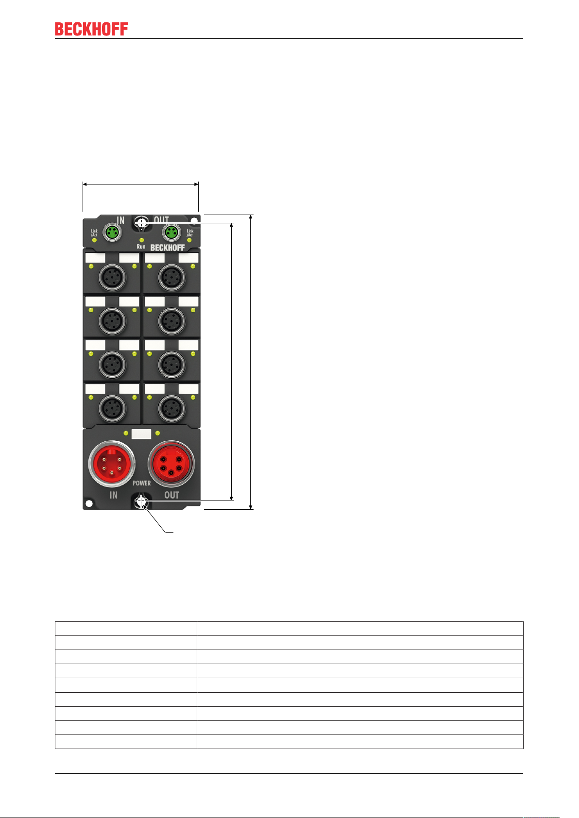
3 Mounting and connections.....................................................................................................................27
3.1 Mounting..........................................................................................................................................27
3.1.1 Dimensions ...................................................................................................................... 27
3.1.2 Fixing ............................................................................................................................... 28
3.1.3 Functional earth (FE) ....................................................................................................... 28
3.2 Connections.....................................................................................................................................29
3.2.1 Connector overview ......................................................................................................... 29
3.2.2 EtherCAT: X40 and X41 .................................................................................................. 30
3.2.3 Supply voltages: X60 and X61......................................................................................... 32
3.2.4 Incremental encoders: X03 or X04 .................................................................................. 34
3.2.5 Limit switch: X05.............................................................................................................. 35
3.2.6 Latch input: X06............................................................................................................... 36
3.2.7 Motor brake: X07 ............................................................................................................. 37
3.2.8 Stepper motor: X08.......................................................................................................... 38
4 Commissioning and configuration ........................................................................................................40
4.1 Integrating EP7047 into a TwinCAT project ....................................................................................40
4.2 Parameterizing EP7047...................................................................................................................41
4.2.1 Open the parameter directory (CoE) ............................................................................... 41
4.2.2 Setting important motor parameters ................................................................................ 42
4.2.3 Setting other important parameters ................................................................................. 44
4.3 Setting the operating mode .............................................................................................................45
4.3.1 Operating modes ............................................................................................................. 46
4.4 Parameterizing the NC axis.............................................................................................................52
4.4.1 Parameterizing the encoder............................................................................................. 54
4.4.2 Parameterizing the controller........................................................................................... 56
4.5 Performing a test run .......................................................................................................................58
4.5.1 Test run with TwinCAT NC .............................................................................................. 58
EP7047-1032 3Version: 1.0
Page 4

Table of contents
4.5.2 Test run without the TwinCAT NC ................................................................................... 59
4.6 Further applications .........................................................................................................................60
4.6.1 Using the "Positioning Interface" ..................................................................................... 60
4.6.2 Linking an NC axis with EP7047...................................................................................... 75
4.6.3 Determining the voltage constant of a motor experimentally........................................... 76
4.6.4 Restoring the delivery state ............................................................................................. 77
4.7 Decommissioning ............................................................................................................................78
5 Diagnosis..................................................................................................................................................79
5.1 Diagnostics – basic principles of diag messages ............................................................................79
5.2 Diag Messages of EtherCAT devices for drive technology .............................................................88
6 CoE parameters .......................................................................................................................................89
6.1 Object directory ...............................................................................................................................89
6.2 Data format of CoE parameters.......................................................................................................91
6.3 Object description............................................................................................................................92
6.3.1 Objects for parameterization............................................................................................ 92
6.3.2 Status objects .................................................................................................................. 96
6.3.3 Standard objects.............................................................................................................. 97
7 Appendix ..................................................................................................................................................99
7.1 General operating conditions...........................................................................................................99
7.2 Accessories ...................................................................................................................................100
7.3 Version identification of EtherCAT devices ...................................................................................101
7.3.1 Beckhoff Identification Code (BIC)................................................................................. 105
7.4 Support and Service ......................................................................................................................107
EP7047-10324 Version: 1.0
Page 5

Foreword
1 Foreword
1.1 Notes on the documentation
Intended audience
This description is only intended for the use of trained specialists in control and automation engineering who
are familiar with the applicable national standards.
It is essential that the documentation and the following notes and explanations are followed when installing
and commissioning these components.
It is the duty of the technical personnel to use the documentation published at the respective time of each
installation and commissioning.
The responsible staff must ensure that the application or use of the products described satisfy all the
requirements for safety, including all the relevant laws, regulations, guidelines and standards.
Disclaimer
The documentation has been prepared with care. The products described are, however, constantly under
development.
We reserve the right to revise and change the documentation at any time and without prior announcement.
No claims for the modification of products that have already been supplied may be made on the basis of the
data, diagrams and descriptions in this documentation.
Trademarks
Beckhoff®, TwinCAT®, EtherCAT®, EtherCATG®, EtherCATG10®, EtherCATP®, SafetyoverEtherCAT®,
TwinSAFE®, XFC®, XTS® and XPlanar® are registered trademarks of and licensed by Beckhoff Automation
GmbH. Other designations used in this publication may be trademarks whose use by third parties for their
own purposes could violate the rights of the owners.
Patent Pending
The EtherCAT Technology is covered, including but not limited to the following patent applications and
patents: EP1590927, EP1789857, EP1456722, EP2137893, DE102015105702 with corresponding
applications or registrations in various other countries.
EtherCAT® is registered trademark and patented technology, licensed by Beckhoff Automation GmbH,
Germany.
Copyright
© Beckhoff Automation GmbH & Co. KG, Germany.
The reproduction, distribution and utilization of this document as well as the communication of its contents to
others without express authorization are prohibited.
Offenders will be held liable for the payment of damages. All rights reserved in the event of the grant of a
patent, utility model or design.
EP7047-1032 5Version: 1.0
Page 6

Foreword
1.2 Safety instructions
Safety regulations
Please note the following safety instructions and explanations!
Product-specific safety instructions can be found on following pages or in the areas mounting, wiring,
commissioning etc.
Exclusion of liability
All the components are supplied in particular hardware and software configurations appropriate for the
application. Modifications to hardware or software configurations other than those described in the
documentation are not permitted, and nullify the liability of Beckhoff Automation GmbH & Co. KG.
Personnel qualification
This description is only intended for trained specialists in control, automation and drive engineering who are
familiar with the applicable national standards.
Description of instructions
In this documentation the following instructions are used.
These instructions must be read carefully and followed without fail!
DANGER
Serious risk of injury!
Failure to follow this safety instruction directly endangers the life and health of persons.
WARNING
Risk of injury!
Failure to follow this safety instruction endangers the life and health of persons.
CAUTION
Personal injuries!
Failure to follow this safety instruction can lead to injuries to persons.
NOTE
Damage to environment/equipment or data loss
Failure to follow this instruction can lead to environmental damage, equipment damage or data loss.
Tip or pointer
This symbol indicates information that contributes to better understanding.
EP7047-10326 Version: 1.0
Page 7

Foreword
1.3 Documentation Issue Status
Version Comment
1.0 • First release
Firmware and hardware versions
This documentation refers to the firmware and hardware version that was applicable at the time the
documentation was written.
The module features are continuously improved and developed further. Modules having earlier production
statuses cannot have the same properties as modules with the latest status. However, existing properties
are retained and are not changed, so that older modules can always be replaced with new ones.
Documentation Firmware Hardware
1.0 06 00
The firmware and hardware version (delivery state) can be found in the batch number (D-number) printed on
the side of the EtherCAT Box.
Syntax of the batch number (D-number)
D: WW YY FF HH
WW - week of production (calendar week)
YY - year of production
FF - firmware version
HH - hardware version
Further information on this topic: Version identification of EtherCAT devices [}101].
Example with D no. 29 10 02 01:
29 - week of production 29
10 - year of production 2010
02 - firmware version 02
01 - hardware version 01
EP7047-1032 7Version: 1.0
Page 8
Product overview
2 Product overview
2.1 Introduction
Stepper motor box with incremental encoder and field-oriented control, 48 V DC, 5 A
The EP7047-0032 EtherCAT Box is designed for the medium performance range of stepper motors. The
PWM output stages cover a wide range of voltages and currents. They are housed in the EtherCAT Box,
together with two inputs for limit switches. The EP7047-0032 can be adapted to the motor and the
application with just a few parameters. The torsionally stiff integrated encoder (1024 inc/rev) makes the
AS2000 stepper motor ideal for closed-loop control of the EP7047-0032. Either a 5 V or a 24 V single-ended
version can be used as an encoder.
Quick links
Technical data [}9]
Process image [}11]
Connections [}29]
Commissioning and configuration [}40]
EP7047-10328 Version: 1.0
Page 9

2.2 Technical data
All values are typical values over the entire temperature range, unless stated otherwise.
EtherCAT
Connection 2x M8 socket, 4-pin, green
Electrical isolation 500V
Supply voltages
Connection Input: 7/8" plug, 5-pin
Downstream connection: 7/8" socket, 5-pin
US nominal voltage 24VDC (-15%/ +20%)
US sum current
Current consumption from U
UP nominal voltage 8…48V
UP sum current
Current consumption from U
1)
S
max. 16Aat 40°C
120mA + current consumption of connected devices:
• encoder
• motor brake
• limit switches
1)
P
max. 16A at 40°C
= current consumption of the stepper motor
DC
Product overview
Stepper motor
Motor type 2-phase stepper motor, unipolar or bipolar
Connection 1x M12 socket, 5-pin
Current per phase max. 5A (overload-proof and short-circuit proof)
Maximum step frequency Adjustable:
1000/ 2000/ 4000/ 8000/ 16000 full steps per second
Microstepping up to 64x
2)
Current controller frequency approx. 30 kHz
Resolution approx. 5000 positions per revolution in typical applications
Encoder input
Number 1
encoder type Incremental encoders
Connection 1x M12 socket, 5-pin
Encoder supply Alternatively:
• 5VDC, max 0.5A, short-circuit proof
• 24V
max. 0.5A, not short-circuit proof
DC,
signals A, B, C; single-ended
(C = reference pulse / zero pulse)
Signal voltage "0" -3…2V
Signal voltage "1" 3.7…28V
Pulse frequency max. 400,000 increments per second (4-fold evaluation)
1)
This value corresponds to the current carrying capacity of the connections for the supply voltages.
2)
automatic switching, speed-dependent.
EP7047-1032 9Version: 1.0
Page 10

Product overview
Digital inputs for limit switches
Number 2
Nominal voltage high level 24V
DC
Digital output for the motor brake
Nominal voltage 24VDC from the control voltage U
S
Output current max. 0,5A
Environmental conditions
Ambient temperature during operation -25…+60°C
Ambient temperature during storage -40…+85°C
Vibration/ shock resistance conforms to EN60068-2-6/ EN60068-2-27
EMC immunity/ emission conforms to EN61000-6-2/ EN61000-6-4
Protection class IP65, IP66, IP67 conforms to EN60529
Housing data
Dimensions Wx Hx D 60mmx 150mmx 26,5mm (without connectors)
Weight approx. 440g
Material PA6 (polyamide)
Installation position variable
Approvals
Approvals CE, UL in preparation
2.3 Scope of supply
Make sure that the following components are included in the scope of delivery:
• 1x EP7047-1032 EtherCAT Box
• 1x Protective cap for supply voltage output, 7/8”, black (pre-fitted)
• 2x protective cap for EtherCAT socket, M8, green (pre-assembled)
• 10x labels, blank (1 strip of 10)
Pre-assembled protective caps do not ensure IP67 protection
Protective caps are pre-assembled at the factory to protect connectors during transport. They may
not be tight enough to ensure IP67 protection.
Ensure that the protective caps are correctly seated to ensure IP67 protection.
EP7047-103210 Version: 1.0
Page 11
Product overview
2.4 Process image
The scope of the process image is adjustable.
EP7047-1032 has several predefined variants of the process image: "Predefined PDO Assignments". Select
the "Predefined PDO Assignment" according to the operating mode [}45].
The factory default setting is "Velocity control compact" [}12].
2.4.1 "Predefined PDO Assignments"
Name Process image Process data objects
Position control
ENC Status [}13]
STM Status [}15]
ENC Control [}16]
STM Control [}17]
STM Position [}17]
Positioning interface
Positioning interface (Auto
start)
Positioning interface (Auto
start) with info data
ENC Status [}13]
STM Status [}15]
POS Status [}14]
ENC Control [}16]
STM Control [}17]
POS Control [}16]
ENC Status [}13]
STM Status [}15]
POS Status [}14]
ENC Control [}16]
STM Control [}17]
POS Control [}16]
POS Control 2 [}16]
ENC Status [}13]
STM Status [}15]
EP7047-1032 11Version: 1.0
STM Synchron info data [}15]
POS Status [}14]
ENC Control [}16]
STM Control [}17]
POS Control [}16]
POS Control 2 [}16]
Page 12
Product overview
Name Process image Process data objects
Positioning interface compact
ENC Status [}13]
STM Status [}15]
POS Status compact [}14]
ENC Control [}16]
STM Control [}17]
POS Control compact [}16]
Velocity control
Velocity control compact
(Factory setting)
Velocity control compact with
info data
ENC Status [}13]
STM Status [}15]
ENC Control [}16]
STM Control [}17]
STM Velocity [}17]
ENC Status compact [}13]
STM Status [}15]
ENC Control compact [}16]
STM Control [}17]
STM Velocity [}17]
ENC Status compact [}13]
STM Status [}15]
STM Synchron info data [}15]
ENC Control compact [}16]
STM Control [}17]
STM Velocity [}17]
EP7047-103212 Version: 1.0
Page 13

Product overview
2.4.2 Process data objects
2.4.2.1 "ENC status"
"ENC Status" contains the status variables of the encoder input. "ENC" is the abbreviation for "Encoder".
Status
• Latch C valid: A signal edge has been detected at
encoder signal "C". As a result, the "Counter value"
was written to the variable "Latch value" at the time of
the signal edge.
• Latch extern valid: A signal edge was detected at
the latch input X06 [}36]. As a result, the counter
value was written to the variable "Latch value" at the
time of the signal edge.
• Set counter done: The value from "Set counter
value" was written to the variable "Counter value" after
setting of "Set counter" (ENC Control [}16]).
• Counter underflow: The counter value "Counter
value" has fallen below the value 0.
• Counter overflow: The counter value "Counter value"
has exceeded the maximum value.
• Extrapolation stall: The extrapolated part of the
counter is invalid ("Micro increments").
• Status of input A: Current signal level of encoder
signal "A" (X03 / X04 [}34])
• Status of input B: Current signal level of encoder
signal "B" (X03 / X04 [}34])
• Status of input C: Current signal level of encoder
signal "C" (X03 / X04 [}34])
• Status of extern latch: Current signal level at the
latch input (X06 [}36])
• Sync error: Distributed Clocks synchronization error
in the previous cycle.
• TxPDO Toggle: This bit is inverted each time an input
data update occurs.
1)
1)
Counter value: The current counter value.
Latch value: Counter value stored at the time of the last
signal edge at latch input X06 or encoder signal "C".
1)
The latch function is deactivated in the factory setting. You may activate and configure the latch function in
1)
process data object "ENC Control" [}16] or "ENC Control compact" [}16].
2.4.2.2 "ENC Status compact"
This process data object is identical with "ENC status" [}13], see there.
EP7047-1032 13Version: 1.0
Page 14
Product overview
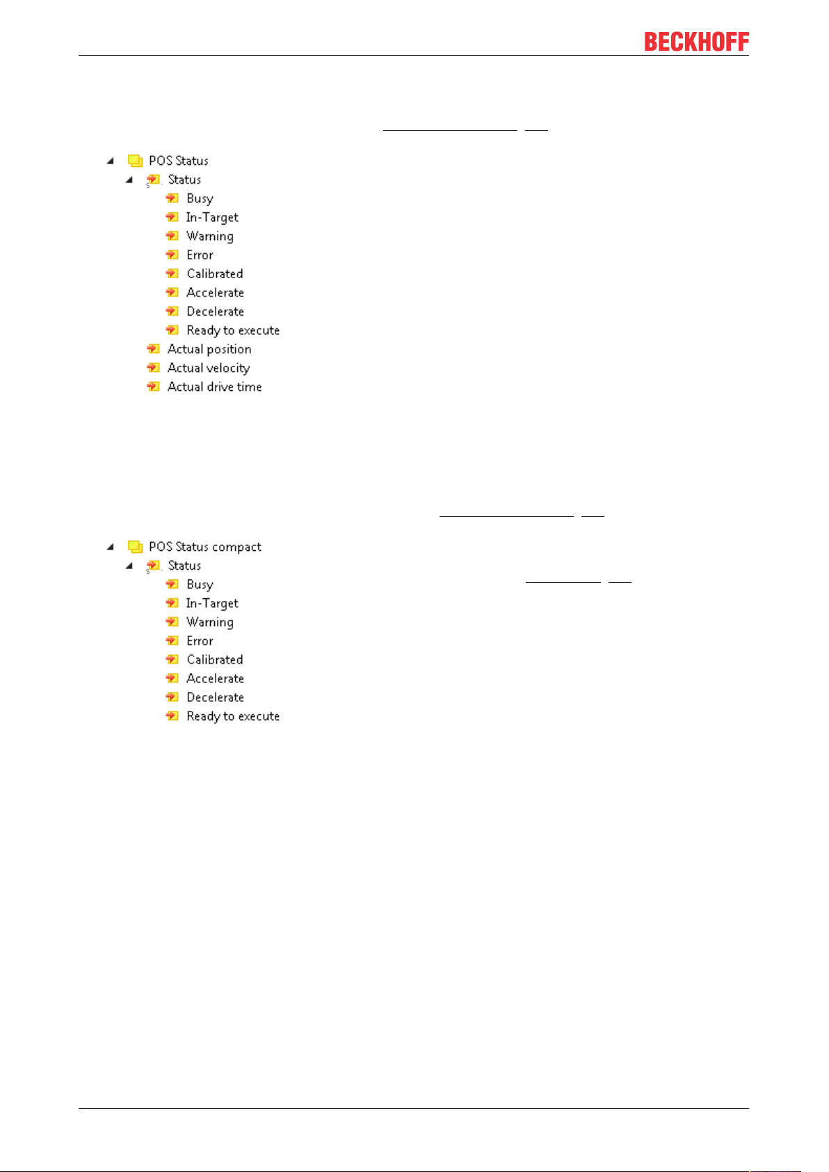
2.4.2.3 "POS Status"
"POS Status" contains the status variables of the Positioning Interface [}60].
Status
• Busy: A motion command is active.
• In-Target: The target position of the motion command
has been reached.
• Warning: Warning message.
• Error: Error message.
• Calibrated: The motor is calibrated.
• Accelerate: The motor accelerates.
• Decelerate: The motor brakes.
• Ready to execute: Ready for a motion command.
Actual position: current set position
Actual velocity: current set velocity
Actual drive time: the elapsed time of the motion
command.
2.4.2.4 "POS Status compact"
"POS Status compact" contains the status variables of the Positioning Interface [}60].
Status
This variable is identical to the "Status" variable in the
process data object "POS Status [}14]". See there.
EP7047-103214 Version: 1.0
Page 15
Product overview
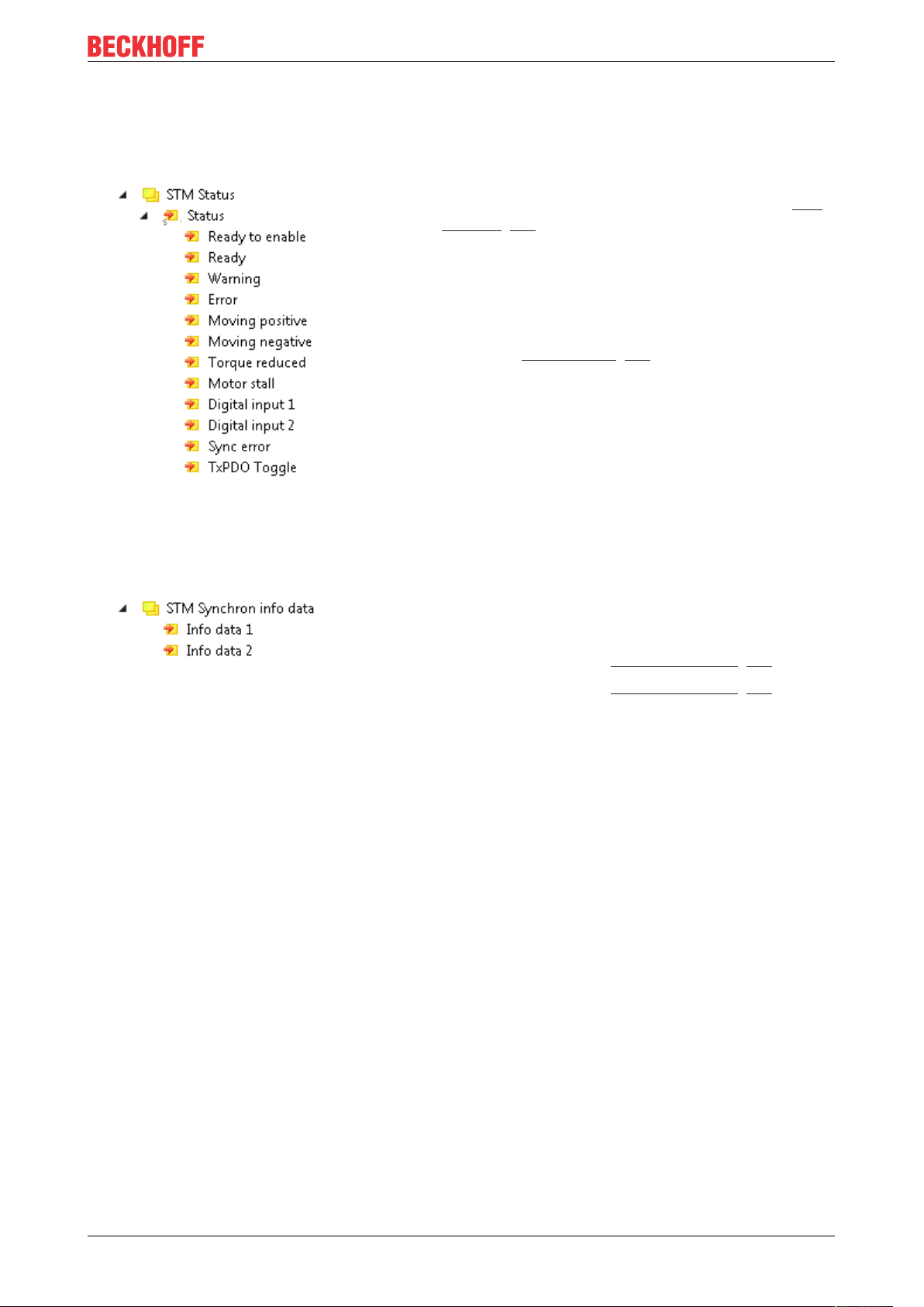
2.4.2.5 "STM Status"
„STM Status" contains the status bits of the stepper motor output stage. "STM" is the abbreviation for
"Stepper Motor".
Ready to enable: The output stage can be enabled. See
output variable "Enable" in the process data object STM
Control [}17].
Ready: The output stage is enabled.
Warning: Warning message.
Error: Error message. The output stage was switched
off due to an error. You can acknowledge the error
message with the output variable "Reset" in the process
data object STM Control [}17]
Moving positive: The speed is greater than 0.
Moving negative: The speed is less than 0.
Motor stall: A loss of step has occurred.
2.4.2.6 "STM Synchronous info data"
"STM" is the abbreviation for "Stepper Motor".
Info data n: Additional information from the box.
You can select what information these variables should
contain:
• Parameter 8012:11
• Parameter 8012:19
Select info data 1 [}94]
hex
Select info data 2 [}94]
hex
EP7047-1032 15Version: 1.0
Page 16

Product overview
2.4.2.7 "ENC Control"
Enable latch C: Activate edge trigger for encoder input
"C".
Enable latch extern on positive edge: Activate edge
trigger for positive signal edges at latch input X06
[}36].
Set counter: Accept the value of the variable "Set
counter value" as the current counter value.
Enable latch extern on negative edge: Activate edge
trigger for negative signal edges at latch input X06
[}36].
Set counter value: Default value for "Set counter".
2.4.2.8 "ENC Control compact"
This process data object is identical with "ENC Control" [}16].
2.4.2.9 "POS Control"
This process data object contains variables for controlling the Positioning Interface [}60].
2.4.2.10 "POS Control 2"
This process data object contains variables for controlling the Positioning Interface [}60].
2.4.2.11 "POS Control compact"
This process data object contains variables for controlling the Positioning Interface [}60].
EP7047-103216 Version: 1.0
Page 17
Product overview
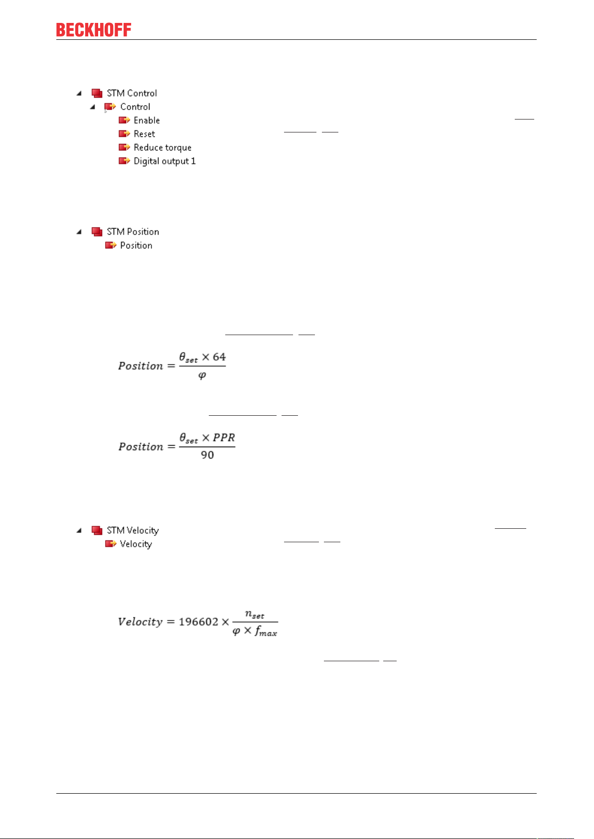
2.4.2.12 "STM Control"
Enable: Enable output stage.
Reset: Acknowledge error message, reset error status.
See input variable "Error" in the process data object STM
Status [}15]
2.4.2.13 "STM Position"
Position: Position setpoint.
Specify the position setpoint in increments.
Conversion from degrees (°) to increments: See below.
Conversion of position setpoints
The formula for converting a position setpoint from degrees (°) to increments depends on whether you are
using an encoder.
• If you are not using an encoder (feedback type [}94] = "Internal counter" ), use this formula:
Position: Setpoint [increments]
Θ
: Setpoint [°]
set
φ: Step angle of the motor [°]
(for AS10xx stepper motors: φ=1.8°)
• If you are using an encoder (feedback type [}94] = "Encoder" ), use this formula:
Position: Setpoint [increments]
Θ
: Setpoint [°]
set
PPR: Resolution of the encoder [increments/revolution]
(for AS10xx stepper motors: inc = 1024)
2.4.2.14 "STM Velocity"
Velocity: Speed setpoint in % of the parameter "Speed
range" [}44].
32767
-100%.
Conversion of speed setpoints
corresponds to 100%, -32767
dec
Velocity: Setpoint [increments/s]
n
: Setpoint [rpm]
set
φ: Step angle of the motor [°]
(for AS10xx stepper motors: φ=1.8°)
f
: "Speed range" [}44] [full steps/s]
max
corresponds to
dec
The speed setpoint can be positive or negative, depending on the desired direction of rotation of the motor.
EP7047-1032 17Version: 1.0
Page 18

Product overview
2.5 Technology
EP7047-1032 provides two basic modes of operation.
• In standard mode [}23] all unipolar and bipolar stepper motors that comply with the specifications of
EP7047-1032 can be controlled. Two currents with sine/cosine curve are provided. The current is
clocked with 64 kHz and resolved with up to 64-fold microstepping to achieve a smooth current.
• Extended mode [}25] is based on field-oriented control. This mode can only be used for stepper
motors from Beckhoff. The current is not only provided, but controlled in a comprehensive manner.
Typical stepper motor problems such as pronounced resonance are therefore finally a thing of the past.
Furthermore, the current is adjusted depending on the load, thereby enabling considerable energy
savings and lower thermal loads at the stepper motor.
Realisation of more demanding positioning tasks
More demanding positioning tasks can be realised via the TwinCAT automation software from Beckhoff. Like
other axes, EP7047-1032 is integrated via the TwinCAT System Manager and can be used like standard
servo axes. Special stepper motor features, such as speed reduction in the event of large following errors,
are automatically taken into account via the stepper motor axis option. The effort for changing from a
servomotor to a stepper motor - and back - is no greater than changing from one fieldbus to another one
under TwinCAT.
The output stages of EP7047-1032 have an overload protection in the form of an overtemperature warning
and switch-off. Together with short circuit detection, diagnostic data are accessible in the process image of
the controller. In addition, this status is displayed by LEDs, along with other information. The output stage is
switched on via an Enable-Bit. The motor current can be set and reduced via a parameter value.
Optimum adaptation to the motor and the implementation of energy-saving features require minimum
programming effort. Since all data are set in the form of parameters in the CoE register, it is easily possible
to replace an EtherCAT device or store certain parameters for transfer to the next project. It is therefore no
longer necessary to transfer certain potentiometer settings or to document DIP switch settings.
EP7047-103218 Version: 1.0
Page 19

Product overview
2.5.1 Stepper motor
Stepper motors are electric motors and are comparable with synchronous motors. The rotor is designed as a
permanent magnet, while the stator consists of a coil package. The frequency of the stator rotary field is
always in a fixed ratio relative to the rotor speed. In contrast to synchronous motors, stepper motors have a
large number of pole pairs. In a minimum control configuration, the stepper motor is moved from pole to pole,
or from step to step.
Stepper motors have been around for many years. They are robust, easy to control, and provide high torque.
In many applications, the step counting facility saves expensive feedback systems. Even with the
increasingly widespread use of synchronous servomotors, stepper motors are by no means "getting long in
the tooth". They are considered to represent mature technology and continue to be developed further in
order to reduce costs and physical size, increase torque and improve reliability. For a standard stepper
motor with 200 full steps, the best possible positioning accuracy is approx. 1.8°.
Today, the most widely used type in industry is the hybrid stepper motor type. In this type of motor the rotor
consists of a toothed iron core with one or a few permanent magnets in the rotor core. The rotor is designed
such that the polarity of successive teeth is inverse. This enables the production of motors with a high
number of steps, which is essential for positioning accuracy, combined with a relatively high torque. The
electrical behaviour of such a hybrid stepper motor is comparable with a multipole synchronous servomotor.
However, thanks to the synchronous toothing of stator and rotor, hybrid stepper motors offer a significantly
higher cogging torque.
Hybrid stepper motors with two or more phases are available on the market. Since EP7047-1032 is designed
for two-phase motors, the description focuses on the two-phase type, with the phases referred as A and B in
this documentation.
Stepper motor parameters
• Mechanical system
Irrespective of the drive and the stepper motor itself, the configuration of the mechanism attached to the
motor shaft has significant influence on the achievable control quality.
Natural resonances, load resonances, gear backlash (loose) and static friction have negative affect on the
controllability of the drive system. This often requires "softer" controller parameterisation, which in turn leads
to a higher position lag in the system. Sliding friction can result in reduced efficiency (due to increased
energy demand), but on the other hand it can have a positive effect on the control stability, due to its
dampening effect.
As a general rule, the "stiffer" the mechanics of a drive system, the easier it is to control, which is beneficial
for achieving a small position lag in the drive system.
• Speed
Stepper motors have low maximum speed, which is usually specified as a maximum step frequency.
• Number of phases
Motors with 2 to 5 phases are common. EP7047-1032 supports 2-phase motors. 4-phase motors are
basically 2-phase motors with separate winding ends. They can be connected directly to EP7047-1032.
• Torque
Refers to the maximum motor torque at different speeds. This parameter is usually represented by a
characteristic curve. Stepper motors have comparatively high torque in the lower speed range. In many
applications, this enables them to be used directly without gearing. Compared with other motors, stepper
motors can quite easily provide a holding moment of the same order of magnitude as the torque.
EP7047-1032 19Version: 1.0
Page 20
Product overview
• Cogging torque
In many cases the stepper motors design results in high cogging torque, which can lead to relatively strong
natural resonance in a motor- and load-dependent speed range. In relation to the cogging torque, increased
inertia often leads to a less strong resonance and smoother operation.
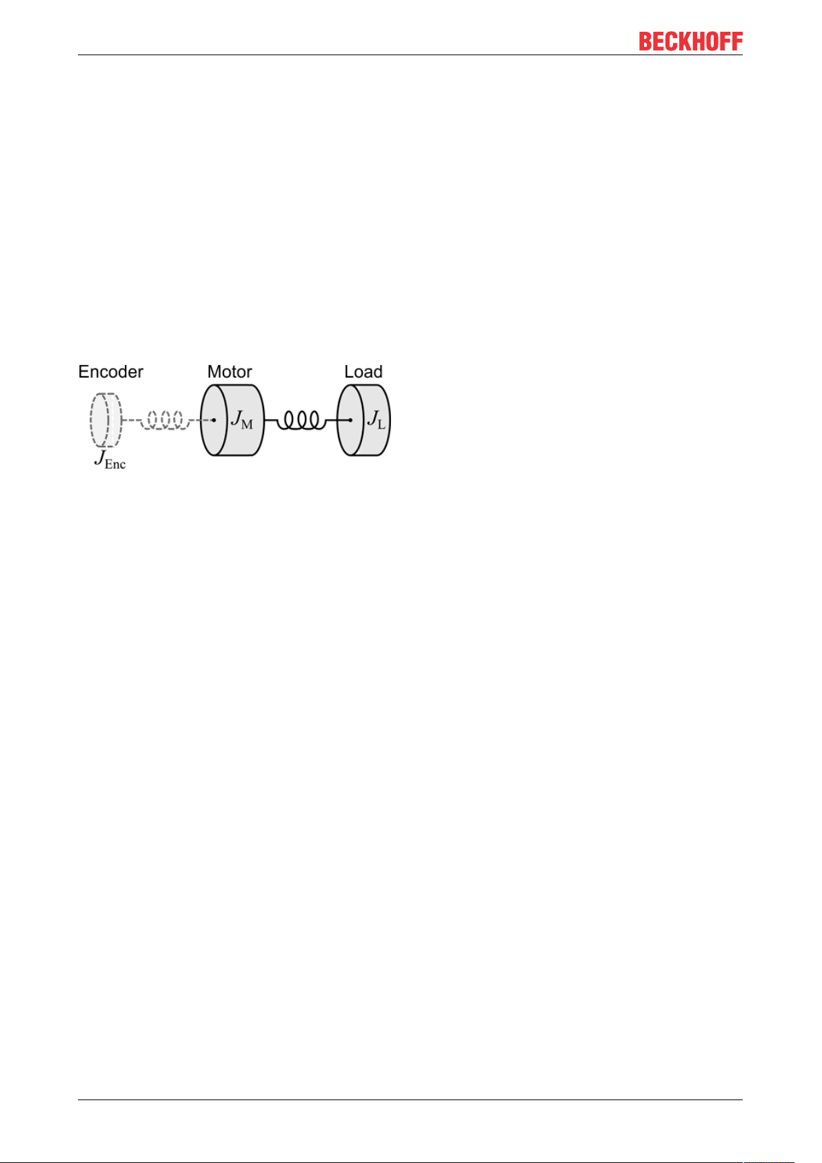
• Mass moment of inertia
In standard mode, the key parameter of the mechanical system is the mass moment of inertia JΣ. It is
essentially composed of the mass moment of inertia of the stepper motor rotor JM and the mass moment of
inertia of the connected load JL. The friction moment J
and the moment of inertia of the encoder J
fric
can be
Enc
neglected in a first approximation.
JƩ ≈ JM + J
L
The ratio between the load torque and the motor torque is defined by the constant kJ.
kJ ≈ JL / J
M
Fig.1: Simplified representation of the mass moments of inertia
As a first approximation, the coupling of the individual masses over the rotor shaft can be modelled as twomass oscillator. The resonance frequency between the motor and the encoder lies in a relatively high
frequency range, which is usually not relevant for stepper motor drives and is suppressed within the drive by
low-pass filtering. The resonance frequency between the motor and the load is frequently in the range
between 20 and 500 Hz. It is therefore often in the operating range of the drive control. Design measures to
reduce the influence of the load resonance include a small load ratio kJ and a rigid coupling of the motor
shaft to the connected load.
• Resonance
At certain speeds, stepper motors run less smoothly. This phenomenon is particularly pronounced when the
motor runs without coupled load, in which case it may even stop (in standard mode). This is caused by
resonance. A distinction can roughly be made between
• resonances in the lower frequency range up to approx. 250Hz; and
• resonances in the medium to upper frequency range.
Resonances in the medium to upper frequency range essentially result from electrical parameters such as
inductance of the motor winding and supply line capacity. They can be controlled relatively easily through
high pulsing of the control system.
Resonances in the lower range essentially result from the mechanical motor parameters. Apart from their
impact on smooth running, such resonances can lead to significant loss of torque, or even loss of step of the
motor, and are therefore particularly undesirable.
In principle, the stepper motor represents an oscillatory system (comparable to a mass/spring system),
consisting of the moving rotor with a moment of inertia and a magnetic field that creates a restoring force that
acts on the rotor. Moving and releasing the rotor creates a damped oscillation. If the control frequency
corresponds to the resonance frequency, the oscillation is amplified, so that in the worst case the rotor will
no longer follow the steps, but oscillate between two positions.
EP7047-1032 prevents this effect thanks to the field-oriented control (Extended Operation Modes) for all
Beckhoff stepper motors.
EP7047-103220 Version: 1.0
Page 21

Product overview
•Torque constant
In the Extended Operation Modes the torque constant kT is used as an additional parameter for the
mechanical controlled system. It indicates the ratio between the torque-forming motor current and the active
torque at the shaft. However, since the field-oriented operating mode is not common for stepper motors, the
torque constant is usually not listed in the motor data sheet.
Electrical system
• Nominal voltage, supply voltage and winding resistance
Under steady-state conditions, the rated current at the rated voltage depends on the winding resistance. This
voltage should not be confused with the supply voltage of the power output stage. EP7047-1032 applies a
controlled current to the motor winding. If the supply voltage falls below the nominal voltage, the power
output stage can no longer apply the full current, resulting in a loss of torque. It is desirable to aim for
systems with small winding resistance and high supply voltage in order to limit warming and achieve high
torque at high speeds.
• Induced countervoltage
Like servomotors, hybrid stepper motors induce a voltage ui [Vs/rad] in the stator winding of the motor, which
is proportional to the speed. It is also referred to as Back Electromotive Force (BEMF). In conjunction with
the DC link voltage (motor voltage), the induced countervoltage determines the physically achievable
maximum speed of the motor.
The ratio of the magnitude of the induced countervoltage and the motor speed varies depending on the
design and is described via the voltage constant ke.
ui = ke·ω
m
The motor parameter ke [mV/(rad/s)] is required for step loss recognition without encoder.
For stepper motors where the voltage constant is not specified in the data sheet, it can be relatively easily
determined using a digital multimeter. To this end the motor to be measured must be operated (within the
rated speed range) by an auxiliary motor via a coupling with constant speed. The motor phases of the motor
to be measured must be open (not connected or shorted). The multimeter can then be used to determine the
RMS value of the induced countervoltage, and therefore the voltage constant, at one of the two open motor
phases (A or B).
• Step angle
The step angle indicates the angle travelled during each step. Typical values are 3.6°, 1.8° and 0.9°. This
corresponds to 100, 200 and 400 steps per motor revolution. Together with the downstream transmission
ratio, this value is a measure for the positioning accuracy. For technical reasons, the step angle cannot be
reduced below a certain value. Positioning accuracy can only be improved further by mechanical means
(transmission). An elegant solution for increasing the positioning accuracy is the microstepping function. It
enables up to 64 intermediate steps. The smaller "artificial" step angle has a further positive effect: The drive
can be operated at higher speed, yet with the same precision. The maximum speed is unchanged, despite
the fact that the drive operates at the limit of mechanical resolution.
• Winding resistance, winding inductance
The winding inductance and winding resistance of the stepper motor stator determine the electrical motor
time constant Te = L / R, which is a key parameter for current controller configuration.
EP7047-1032 21Version: 1.0
Page 22

Product overview
2.5.2 Selecting a stepper motor
Specifying the stepper motor
1. Determine the required positioning accuracy and hence the step resolution. The first task is to determine the maximum resolution that can be achieved. The resolution can be increased via mechanical
gear reduction devices such as spindles, gearing or toothed racks. The 64-fold microstepping also has
to be taken into account.
2. Determine mass m and moment of inertia (J) of all parts to be moved
3. Calculate the acceleration resulting from the temporal requirements of the moved mass.
4. Calculate the forces from mass, moment of inertia, and the respective accelerations.
5. Convert the forces and velocities to the rotor axis, taking account of efficiencies, moments of friction
and mechanical parameters such as gear ratio. It is often best to start the calculation from the last
component, usually the load. Each further element transfers a force and velocity and leads to further
forces or torques due to friction. During positioning, the sum of all forces and torques acts on the motor shaft. The result is a velocity/torque curve that the motor has to provide.
6. Using the characteristic torque curve, select a motor that meets these minimum requirements. The
moment of inertia of the motor has to be added to the complete drive. Verify your selection. In order to
provide an adequate safety margin, the torque should be oversized by 20% to 30%. The optimisation
is different if the acceleration is mainly required for the rotor inertia. In this case, the motor should be
as small as possible.
7. Test the motor under actual application conditions: Monitor the housing temperatures during continuous operation. If the test results do not confirm the calculations, check the assumed parameters and
boundary conditions. It is important to also check side effects such as resonance, mechanical play,
settings for the maximum operation frequency and the ramp slope.
8. Different measures are available for optimising the performance of the drive: using lighter materials or
hollow instead of solid body, reducing mechanical mass. The control system can also have significant
influence on the behaviour of the drive. EP7047-1032 enables operation with different supply voltages.
The characteristic torque curve can be extended by increasing the voltage. In this case, a current increase factor can supply a higher torque at the crucial moment, while a general reduction of the current can significantly reduce the motor temperature. For specific applications, it may be advisable to
use a specially adapted motor winding.
EP7047-103222 Version: 1.0
Page 23
Product overview
2.5.3 Standard mode
Stepper motors were originally operated with very simple output stages, which were only able to switch the
voltage of the motor phases separately (nowadays current control takes place via PWM with pulse-width
modulation as standard). Initially the motor phases there were controlled individually in turn. A switching
sequence in the positive direction of rotation corresponds to the switching sequence (+A, +B, -A, -B).
Sequential switching results in rather irregular operation in this mode. In order to make the operation
smoother, so-called microstepping was introduced later, in which the four set voltages were extended by
intermediate values (e.g. from a stored sine table). These days, microstepping based on 64 steps is
commonly used.
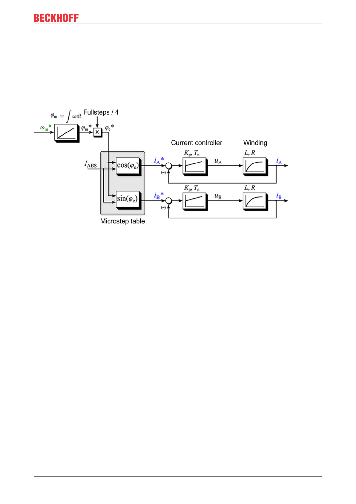
Fig.2: Control structure of a standard stepper motor drive
Neglecting the sampling resulting from the microstepping, the motor current I as function of the electrical
angle φe and of the magnitude of the motor current I
(when using a current controller) can be described as
ABS
follows:
I(φe) = IA+ jIB= I
cos(φe) + jI
ABS
ABS
sin(φe)
Represented by magnitude and angle:
I(φe ) = I
ABS
· e
jφe
It follows that a rotation of the electrical angle φe is equivalent to four full steps. (A stepper motor with 200
full steps therefore has 50 pole pairs).
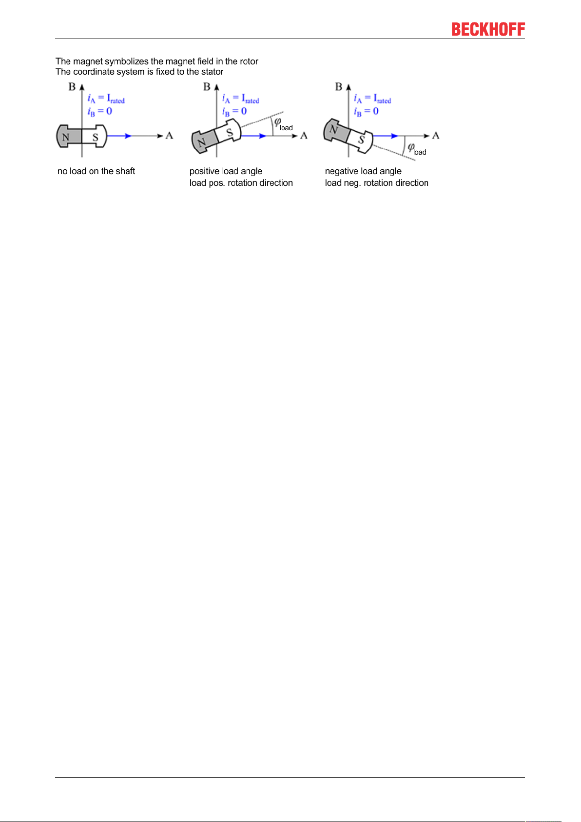
The shaft aligns itself if a constant current is set with no load at the motor shaft. Within a pole pairs the shaft
points in the direction of the active stator field.
If an external load is applied to the motor shaft, the shaft is turned out of the field direction, resulting in a load
angle (also referred to as angular displacement) (relative to an electric rotation of the angle φe). The load
angle depends on the design of the stepper motor itself, the motor current and the torque acting on the shaft.
The relationship is non-linear!
If the load angle exceeds a motor-dependent maximum value (i.e. if the maximum machine torque under
these boundary conditions is exceeded), the load torque can no longer be maintained by the motor. If the
shaft is turned further out of the rotary field, it "tips", resulting in one or more step losses. The "tip angle" may
vary between motor types. Often, it lies between around 45° and 65°.
EP7047-1032 23Version: 1.0
Page 24
Product overview
Fig.3: Behaviour of the rotor under load
The load angle is of interest for the user, because it allows conclusions about the load on the shaft. It is
measured by evaluating the induced countervoltage* and can be used to optimise the drive system.
EP7047-103224 Version: 1.0
Page 25
Product overview
2.5.4 Field-oriented control
In the Extended Operation Modes the stepper motor is operated like a servomotor, based on the principle of
field-oriented control.
Function
The operating behaviour of the motor corresponds to that of a traditional DC motor, with commutation via a
mechanical commutator. With a constant exciter field, the torque of the DC machine is directly proportional to
the stator current and can be directly influenced by it. The exciter field is generated, depending on the
machine type, by permanent magnets or, with a separately excited DC machine, for example, via a separate
excitation winding.
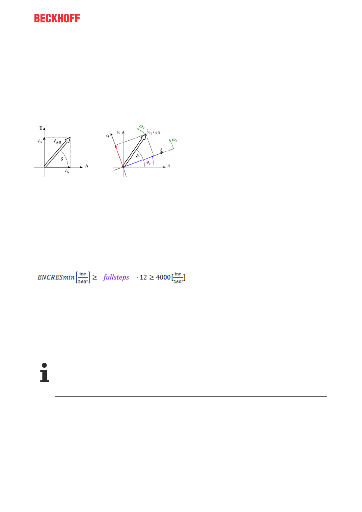
Fig.4: Coordinate transformation of field-oriented control
For servomotors and also hybrid stepper motors, initially there is no direct link between the phase currents
and the torque. Field and torque are decoupled mathematically via Park's transformation. Two current
components, "d" for "direct" in field direction and "q" for "quadrature" in torque-forming direction, are
calculated from the phase currents. Via the torque-forming current component iq, the torque of the machine
can now be regulated directly, like for a DC machine.
A prerequisite is that the rotor position is available with sufficiently high accuracy. For a stepper motor the
encoder resolution should be at least 4000 increments per mechanical revolution, in order to achieve
adequate positioning accuracy. The minimum encoder resolution also depends on the number of full steps
and can be calculated approximately as follows.
Fig.5: Calculation of the resolution
Commutation determination for Extended Operation Modes
Because the absolute actual position is not available for incremental encoders, on system start-up there is
no direct reference to the rotor position, which is required for field-oriented operation. Therefore, the
reference between the actual position and the rotor position must be generated at start-up via a commutation
determination process. During this process the rotor is moved forward and back several times up to two full
steps.
Commutation determination
• The maximum current should be set just below the rated motor current.
• During commutation determination the rotor shaft should not be subject to an external torque. If
this condition is not met, the Extended Operation Modes cannot be used.
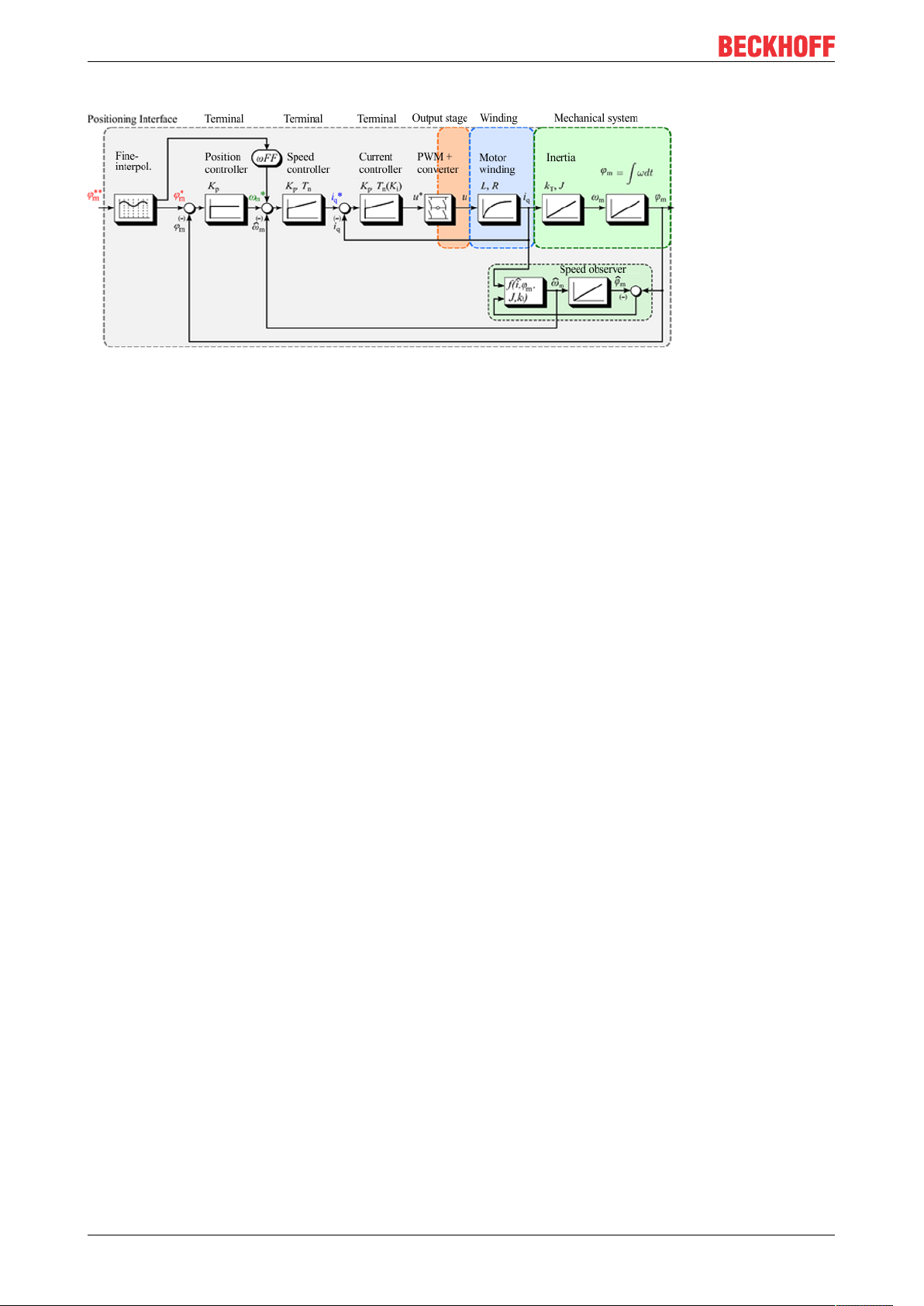
Control structure
The drive control structure is a cascade control structure with a position control loop and a lower-level speed
and current control loop. If a speed setpoint is specified, the external position control loop can be omitted.
EP7047-1032 25Version: 1.0
Page 26
Product overview
Fig.6: Cascade control structure with field-oriented control (Extended Operating modes)
Motor dependency
Due to the fact that the control is strongly dependent on the motor parameters, the controller parameters and
motor behaviour itself, field-oriented control is limited to Beckhoff motors. This mode is not supported for
motors from other manufacturers.
Main advantages compared with standard mode
• Low current consumption (almost full load-dependence)
• High efficiency
• Consistent dynamics compared with standard mode
• Step losses are inherently avoided
Requirement
• Encoder with sufficiently high resolution required (minimum 4000 [INC/360°])
• Slightly higher parametrisation effort required (speed controller)
• Commutation determination at startup (due to incremental encoder)
• Only possible with stepper motors from Beckhoff Automation (AS10xx)
EP7047-103226 Version: 1.0
Page 27
3 Mounting and connections
150
60
141
Ø 4.5
3.1 Mounting
3.1.1 Dimensions
Mounting and connections
Fig.7: Dimensions
All dimensions are given in millimeters.
Housing features
Housing material PA6 (polyamide)
Sealing compound polyurethane
Mounting two fastening holes Ø 4.5 mm for M4
Metal parts brass, nickel-plated
Contacts CuZn, gold-plated
Power feed through max. 16 A at 40°C (according to IEC 60512-3)
Installation position variable
Protection class IP65, IP66, IP67 (conforms to EN 60529) when screwed together
Dimensions (H x W x D) approx. 150 x 60 x 26.5mm (without connectors)
EP7047-1032 27Version: 1.0
Page 28
Mounting and connections
FE
FE
3.1.2 Fixing
NOTE
Dirt during assembly
Dirty connectors can lead to malfunctions. Protection class IP67 can only be guaranteed if all cables and
connectors are connected.
• Protect the plug connectors against dirt during the assembly.
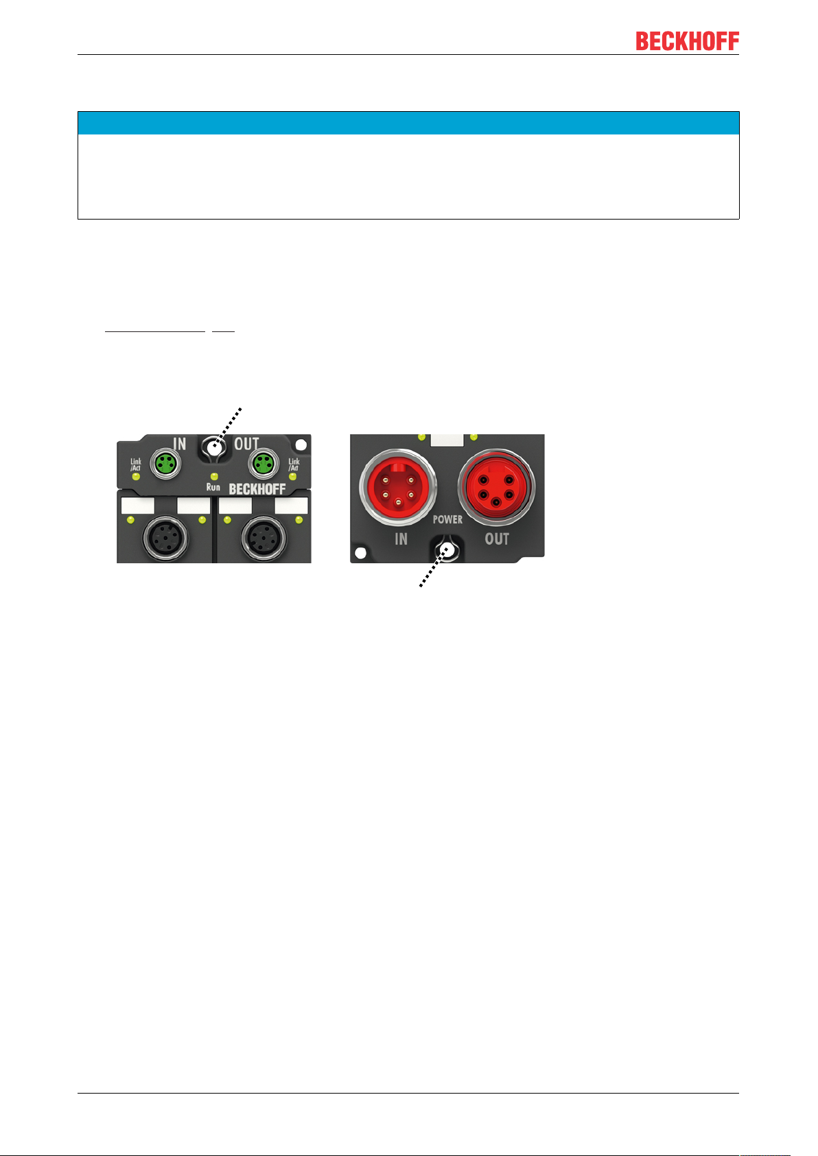
Mount the module with two M4 screws in the centrally located fastening holes.
3.1.3 Functional earth (FE)
The fastening holes [}28] also serve as connections for the functional earth (FE).
Make sure that the box is earthed with low impedance via both fastening screws. You can achieve this, for
example, by mounting the box on a grounded machine bed.
Fig.8: Functional earth via the fastening holes
EP7047-103228 Version: 1.0
Page 29
Mounting and connections
X60 X61
X01
X40 X41
X02
X05
X06
X03
X04
X07
X08
3.2 Connections
NOTE
Risk of confusion with M12 sockets
The M12 sockets X01 to X08 are assigned very different functions. Connecting a plug connector to the
wrong socket can result in damage.
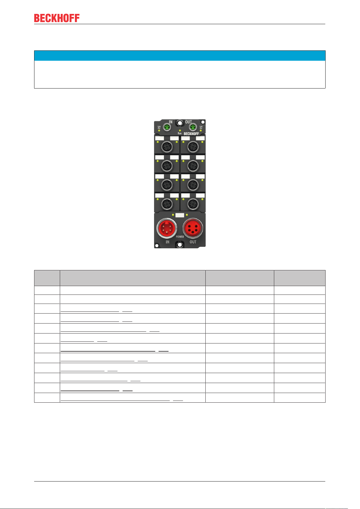
3.2.1 Connector overview
Fig.9: Connector overview
Name Function Connector
type
Tightening
torque
X01 - M12 socket 0.6Nm
X02 - M12 socket 0.6Nm
X03
X04
X05
X06
X07
X08
X40
X41
X60
X61
1)
Mount plugs on these connectors using a torque wrench, e.g. ZB8801 from Beckhoff.
Protective caps
Incremental encoder [}34] with 5 V supply
Incremental encoder [}34] with 24 V supply
Digital inputs for limit switches [}35]
Latch input [}36]
Digital output for the motor brake [}37]
Stepper motor connection [}38]
EtherCAT input [}30]
EtherCAT-Weiterleitung [}30]
Supply voltage input [}32]
Supply voltage downstream connection [}32]
M12 socket 0.6Nm
M12 socket 0.6Nm
M12 socket 0.6Nm
M12 socket 0.6Nm
M12 socket 0.6Nm
M12 socket 0.6Nm
M8 socket 0.4Nm
M8 socket 0.4Nm
7/8“ plug connector 1.5Nm
7/8“ socket 1.5Nm
• Seal unused connectors with protective caps.
• Ensure the correct seating of pre-assembled protective caps.
Protective caps are pre-assembled at the factory to protect connectors during transport. They may not
be tight enough to ensure IP67 protection.
1)
1)
1)
1)
1)
1)
1)
1)
1)
1)
EP7047-1032 29Version: 1.0
Page 30
Mounting and connections
3 1
24
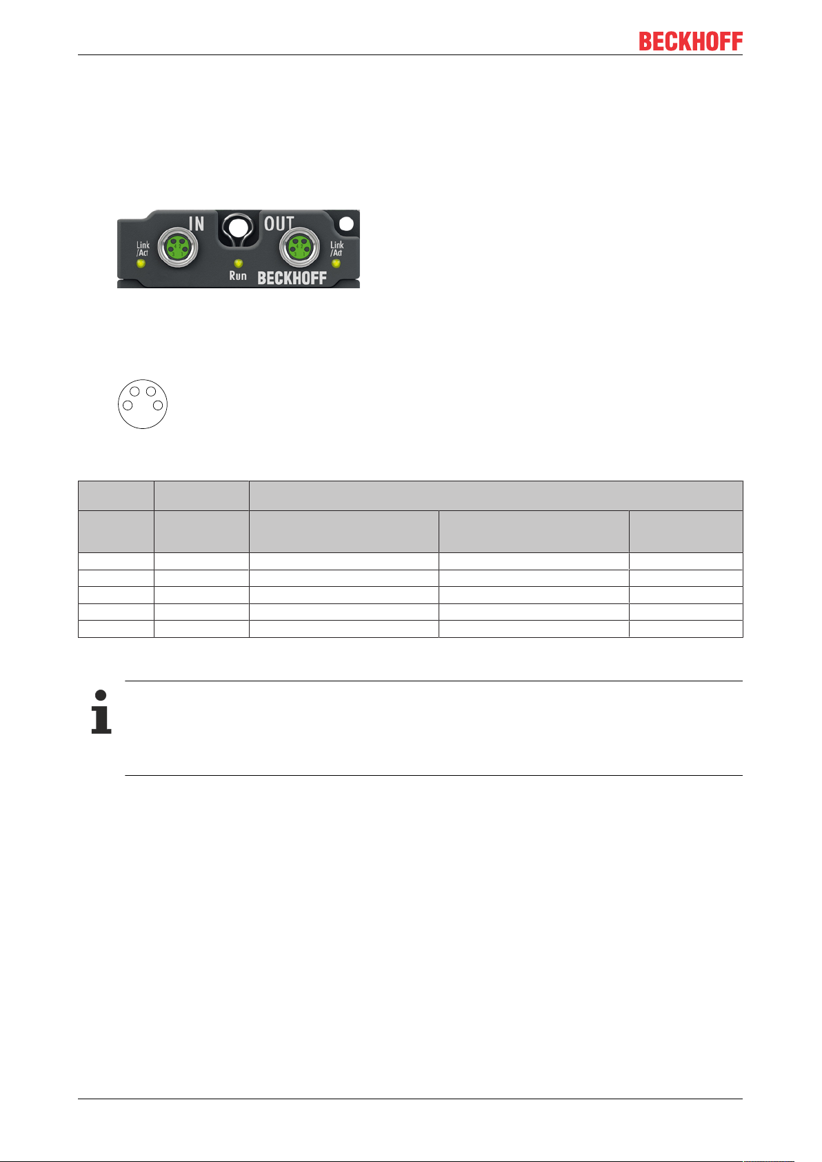
3.2.2 EtherCAT: X40 and X41
3.2.2.1 Connectors
EtherCAT Box Modules have two green M8 sockets for the incoming and downstream EtherCAT
connections.
Fig.10: EtherCAT connectors
Connection
Fig.11: M8 socket
EtherCAT M8
Signal Contact ZB9010, ZB9020, ZB9030, ZB9032,
Tx + 1 yellow
Tx - 4 orange
Rx + 2 white
Rx - 3 blue
Shield Housing Shield Shield Shield
1)
Core colors according to EN61918
connector
Core colors
ZK1090-6292,
ZK1090-3xxx-xxxx
1)
1)
1)
1)
ZB9031 and old versions of
ZB9030, ZB9032, ZK1090-3xxxxxxx
orange/white white/orange
orange orange
blue/white white/green
blue green
TIA-568B
Adaptation of core colors for cables ZB9030, ZB9032 and ZK1090-3xxxx-xxxx
For standardization, the core colors of the ZB9030, ZB9032 and ZK1090-3xxx-xxxx cables have
been changed to the EN61918 core colors: yellow, orange, white, blue. So there are different color
codes in circulation. The electrical properties of the cables have been retained when the core colors
were changed.
EP7047-103230 Version: 1.0
Page 31

Mounting and connections
3.2.2.2 Status LEDs
Fig.12: EtherCAT Status LEDs
L/A (Link/Act)
A green LED labelled "L/A" is located next to each EtherCAT socket. The LED indicates the communication
state of the respective socket:
LED Meaning
off no connection to the connected EtherCAT device
lit LINK: connection to the connected EtherCAT device
flashes ACT: communication with the connected EtherCAT device
Run
Each EtherCAT slave has a green LED labelled "Run". The LED signals the status of the slave in the
EtherCAT network:
LED Meaning
off Slave is in "Init" state
flashes uniformly Slave is in "Pre-Operational“ state
flashes sporadically Slave is in "Safe-Operational" state
lit Slave is in "Operational" state
Description of the EtherCAT slave states
3.2.2.3 Cables
For connecting EtherCAT devices only shielded Ethernet cables that meet the requirements of at least
category5 (CAT5) according to EN50173 or ISO/IEC11801 should be used.
EtherCAT uses four wires for signal transmission.
Thanks to automatic line detection ("Auto MDI-X"), both symmetrical (1:1) or cross-over cables can be used
between Beckhoff EtherCAT.
Detailed recommendations for the cabling of EtherCAT devices
EP7047-1032 31Version: 1.0
Page 32

Mounting and connections
1
2
3
4
5 5
4
3
2
1
Plug
Feed-in
Socket
Forwarding
3.2.3 Supply voltages: X60 and X61
EP7047 requires two supply voltages:
• Control voltage U
• DC link voltage U
S
P
3.2.3.1 Connectors
Two 7/8" connectors at the low-end of the modules are used for feeding and routing the supply voltages:
• "IN" (male): left connector for feeding the supply voltages
• "OUT" (female): right connector for downstream connection
Pin assignment
Fig.13: 7/8" connector pin assignment
NOTE
The input for UP is not protected against reverse polarity.
Defect possible through polarity reversal.
Pin Name Comment Core colors
1 GND
2 GND
P
S
GND to U
GND to U
P
S
Black
Blue
3 FE Functional earth Grey
4 +24 VDC U
5 +48 VDC U
1)
The core colors apply to cables of the type: Beckhoff ZK203x-xxxx.
S
P
Control voltage U
DC link voltage U
S
P
Brown
White
1)
EP7047-103232 Version: 1.0
Page 33

Mounting and connections
Vert. Faktor: 0,45 cm / V
5 10 15 20
2
4
6
8
10
250
0
12
30
Vert. Faktor: 0,45 cm / V
Voltage drop (V)
Cable length (m)
35
8 A
1.5 mm²
4 A
12 A
16 A
3.2.3.2 Status LEDs
The status of the supply voltages is signaled by two LEDs. A Status LED lights up green when the respective
supply voltage is present on the connector for the supply.
3.2.3.3 Conductor losses
Take into account the voltage drop on the supply line when planning a system. Avoid the voltage drop being
so high that the supply voltage at the box lies below the minimum nominal voltage.
Variations in the voltage of the power supply unit must also be taken into account.
Voltage drop on the supply line
EP7047-1032 33Version: 1.0
Page 34

Mounting and connections
1
2
3
4
5
GND
Pin 1
ENC_A
24V
Pin 3
Pin 2
C
B
A
ENC_B
Pin 4
ENC_C
Pin 5
5
4
3
2
1
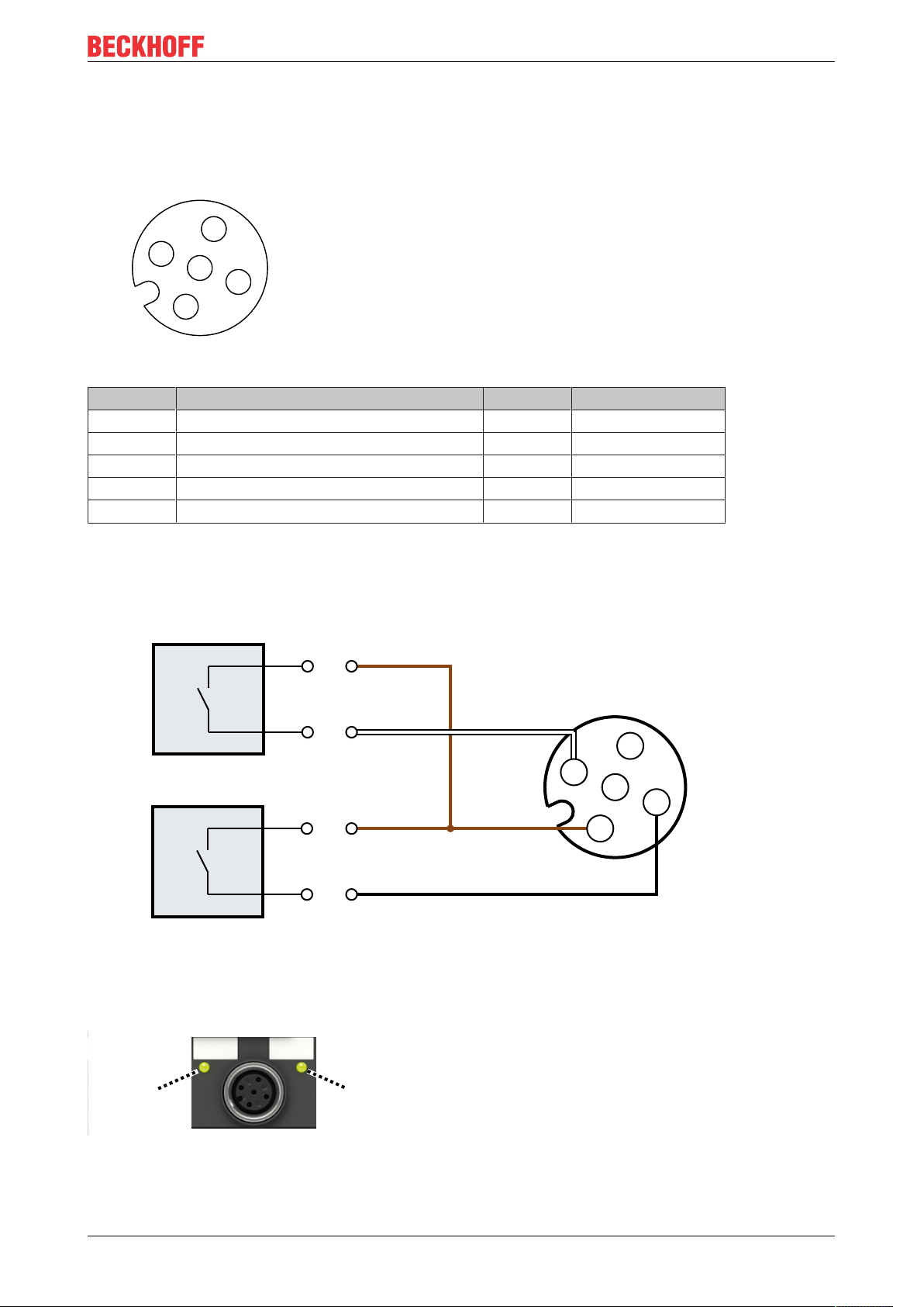
3.2.4 Incremental encoders: X03 or X04
EP7047 has two connectors for incremental encoders, but only one of these may be used:
• X03 for incremental encoders that require 5V supply voltage.
• X04 for incremental encoders that require 24V supply voltage.
NOTE
Only connect one encoder
Connecting two encoders simultaneously can result in damage.
NOTE
The encoder supply at X04 is not short-circuit proof (24V)
Risk of damage due to short circuit.
• Avoid short-circuiting the encoder supply voltage.
Pin assignment
Fig.14: M12 socket
Pin Function X03 X04 Core color
1 0V encoder supply GND
S
2 Encoder supply 5V 24V U
GND
S
S
brown
white
1)
3 Encoder signal input A ENC_A ENC_A blue
4 Encoder signal input B ENC_B ENC_B black
5 Reference pulse / zero pulse ENC_C ENC_C grey
1)
The wire colors apply to M12 encoder cables from Beckhoff: ZK4000-5100-2xxx, ZK4000-5151-0xxx.
Connection example
Fig.15: Connection example: Incremental encoders
EP7047-103234 Version: 1.0
Page 35
3.2.5 Limit switch: X05
1
2
3
4
5
Di1
Pin 4
24V
Pin 1
5
4
3
2
1
Di2
Pin 2
24V
Pin 1
Di1 Di2
You can connect up to two limit switches to X05.
Pin assignment
Fig.16: M12 socket
Mounting and connections
Pin Function Symbol Core color
1 Limit switch supply 24V
DC
US1
2)
brown
1)
2 Digital input2 Di2 white
3 Limit switch supply 0V GND
S
blue
4 Digital input1 Di1 black
5 Functional earth FE grey
1)
The core colors apply to M12 cables from Beckhoff: ZK2000-5xxx, ZK2000-6xxx, ZK2000-7xxx
2)
US1 is branched off from the supply voltage US.
Connection example
Fig.17: Connection example: Two limit switches, two-wire connection
Status LEDs
X05 has two green LEDs. An LED lights up when a high level is detected at the respective input.
Fig.18: Status LEDs for limit switch
EP7047-1032 35Version: 1.0
Page 36

Mounting and connections
1
2
3
4
5
3.2.6 Latch input: X06
Pin assignment
Fig.19: M12 socket
Pin Function Symbol Core color
1 Supply output 24V
DC
US1
2)
brown
1)
2 - - white
3 Supply output 0V
DC
GND
S
blue
4 Latch input LTC black
5 Functional earth FE grey
1)
The core colors apply to M12 cables from Beckhoff: ZK2000-5xxx, ZK2000-6xxx, ZK2000-7xxx
2)
US1 is branched off from the supply voltage US.
EP7047-103236 Version: 1.0
Page 37

3.2.7 Motor brake: X07
1
2
3
4
5
Pin assignment
Fig.20: M12 socket
Mounting and connections
Pin Function Symbol Core color
1)
1 - - brown
2 - - white
3 Ground GND
S
blue
4 Brake output BRK black
5 Functional earth FE grey
1)
The core colors apply to M12 cables from Beckhoff: ZK2000-5xxx, ZK2000-6xxx, ZK2000-7xxx
EP7047-1032 37Version: 1.0
Page 38

Mounting and connections
1
2
3
4
5
A2
A1
B1
5
4
3
2
1
B2
M
3.2.8 Stepper motor: X08
Pin assignment
Fig.21: M12 socket
Pin Function Symbol Core color
1 Motor winding A A1 brown
2 A2 white
3 Motor winding B B1 blue
4 B2 black
5 Functional earth FE grey
1)
The core colors apply to M12 cables from Beckhoff: ZK2000-5xxx, ZK2000-6xxx, ZK2000-7xxx
Connection examples
1)
Fig.22: Connection example: Bipolar stepper motor, serial connection
EP7047-103238 Version: 1.0
Page 39

A2
A1
B1
5
4
3
2
1
B2
M
Fig.23: Connection example: Bipolar stepper motor, parallel connection
A2
A1
B1
5
4
3
2
1
B2
M
Mounting and connections
Fig.24: Connection example: Unipolar stepper motor
In unipolar stepper motors only half of each winding is energized.
EP7047-1032 39Version: 1.0
Page 40

Commissioning and configuration
4 Commissioning and configuration
4.1 Integrating EP7047 into a TwinCAT project
1. Integrate EP7047-1032 as an I/O module in TwinCAT (Quick-Start Guide).
ð A dialog box appears:
You now have two options:
• Click "OK" (recommended) …
◦ … if you want to use the TwinCAT NC functions and you have not yet created the axis to be
controlled in the current TwinCAT project.
• Click "Cancel" …
◦ … if you have already created the axis to be controlled in TwinCAT.
◦ … if you do not want to use the TwinCAT NC functions.
Note: This information is not binding. In other words, you can link an NC axis with EP7047 [}75] at a later
stage or disconnect the link.
When you click "OK":
• In the Solution Explorer under the entry "MOTION", a new NC task "NC-Task 1 SAF" is created if no
NC task is available there yet.
• A new NC axis is created in the NC task under "Axes": „Axisn".
• The newly created NC axis is automatically linked to EP7047.
EP7047-103240 Version: 1.0
Page 41

Commissioning and configuration
1
2
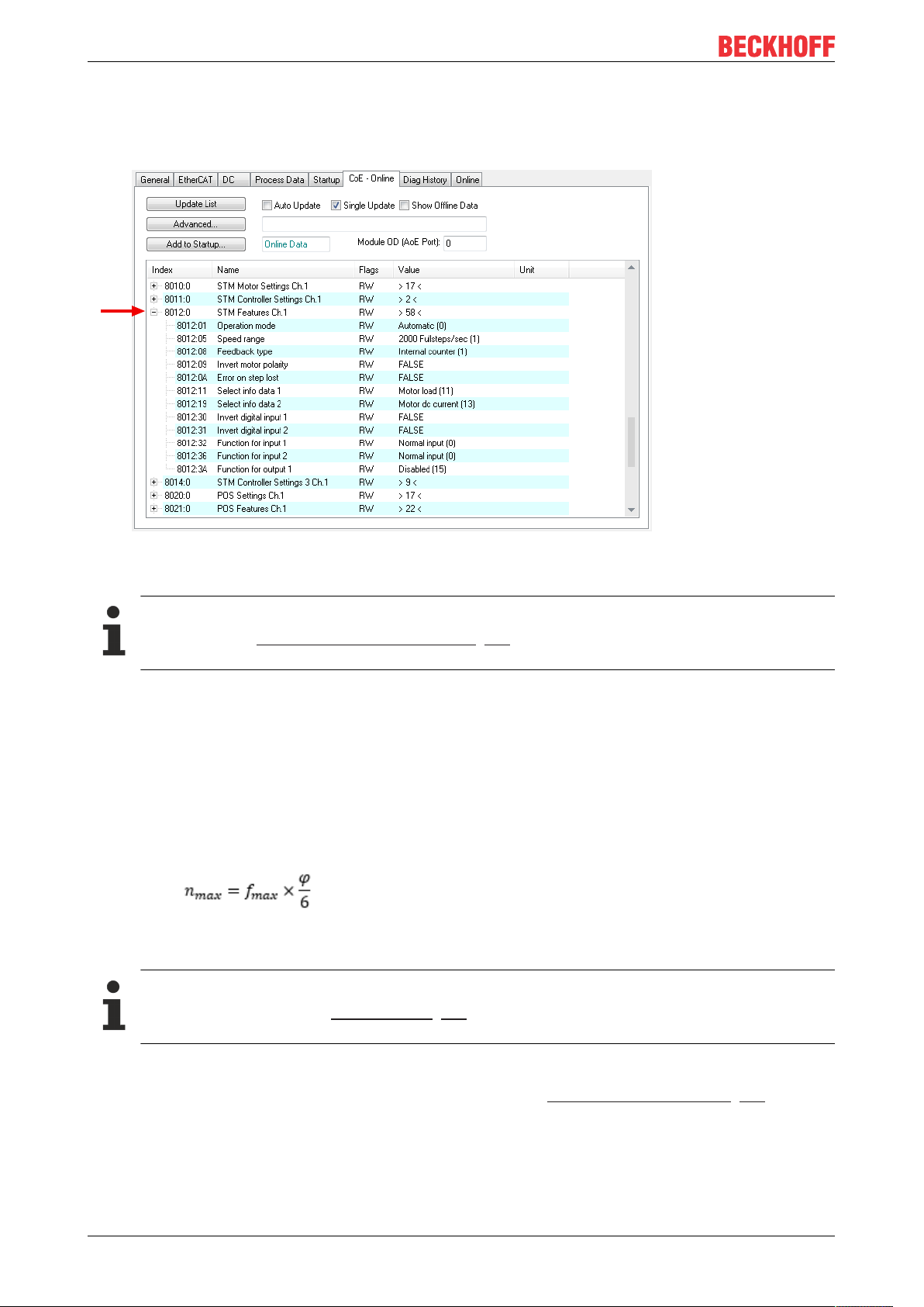
4.2 Parameterizing EP7047
4.2.1 Open the parameter directory (CoE)
1. In the Solution Explorer: double-click EP7047-1032.
2. Click on the "CoE - Online" tab.
ð You will see the CoE directory of EP7047-1032 where you can check and change the parameter values.
Resetting parameters to factory settings
If you do not know whether parameters have already been changed by the present EP7047, you
can reset all parameters to the factory settings [}77].
EP7047-1032 41Version: 1.0
Page 42

Commissioning and configuration
4.2.2 Setting important motor parameters
NOTE
Some motor parameters are not fault-tolerant
Incorrect motor parameters can result in damage.
• Take care when setting the motor parameters.
The motor parameters are stored in CoE object 8010
hex
.
To ensure safe commissioning, it is sufficient to set the following parameters correctly. Further motor
parameters are described under CoE object 8010
: STM Motor Settings Ch.1 [}92].
hex
8010:01 "Maximal current"
The maximum current that the current controller outputs per motor winding.
Unit: mA
Factory setting: 5000
dec
The maximum value that should be entered here is the nominal motor current. The nominal current can
usually be found in the data sheet of the motor.
8010:02 "Reduced current"
Winding current at motor standstill.
Unit: mA
Factory setting: 1000
dec
Criteria for setting this parameter:
• A lower value results in a lower power loss when the motor is at standstill.
• A higher value leads to a higher breakdown torque when the motor is at standstill.
EP7047-103242 Version: 1.0
Page 43

8010:03 "Nominal voltage"
The DC link voltage UP, which you connect to X60 [}32].
Risk of confusion: DC link voltage and nominal motor voltage
• Do not enter the nominal motor voltage here.
Unit: 10mV
Factory setting: 5000
dec
Commissioning and configuration
EP7047-1032 43Version: 1.0
Page 44
Commissioning and configuration
4.2.3 Setting other important parameters
Other important parameters are stored in CoE object 8012
8012:05 "Speed range"
hex
.
When changing "Speed range": adjust "Reference velocity"
Recalculate the parameter "Reference velocity" [}52] if you have changed the parameter "Speed
range".
The "Speed range" parameter has several functions:
• Upper limit of the output step frequency.
• Reference value for speed setpoints:
Speed setpoints are given in % of the "Speed range".
Unit: Full stepspersecond
Factory setting: "2000Fullsteps/sec"
The following formula can be used to determine the maximum achievable speed for a "Speed range":
n
: Maximum achievable speed [rpm]
max
f
: "Speed range" [full steps/s]
max
φ: Step angle of the motor [°]
8012:08 "Feedback type"
When changing the "Feedback type": adjust the "Scaling factor"
Recalculate the parameter Scaling factor [}54] if you have changed the "Feedback type" parameter.
Factory setting: "Internal counter"
• If you are using an encoder, set this parameter to "Encoder". Parameterize the encoder [}54].
• Otherwise set this parameter to "Internal counter".
EP7047-103244 Version: 1.0
Page 45

Commissioning and configuration
4.3 Setting the operating mode
1. Decide which operating mode is required for your application. Selection wizard [}46]
2. Set the operating mode via CoE parameter 8012:01
hex
.
3. Click the "Process data" tab.
4. Select a suitable "Predefined PDO Assignment" for the selected operating mode.
Suitable "Predefined PDO Assignments" for the individual operating modes can be found in chapter
Operating modes [}46].
Note:
- if you have set the "Automatic" [}47] operating mode, the selection of the "Predefined PDO
Assignment" determines the actual operating mode.
- if you select "Positioning Interface [...]", the link to an NC axis is broken.
5. Set all parameters required for the selected operating mode [}46].
EP7047-1032 45Version: 1.0
Page 46

Commissioning and configuration
4.3.1 Operating modes
"Automatic" [}47] (factory setting)
"Velocity direct" [}48]
"Position Controller" [}49]
"Ext. Velocity mode" [}50]
"Ext. Position mode" [}51]
4.3.1.1 Selection wizard
As a rule, the operating modes differ in whether the setpoint is a position or a speed.
Operating modes with position setpoint:
• "Position Controller" [}49]
• "Ext. Position mode" [}51]
Operating modes with speed setpoint:
• "Velocity direct" [}48]
• "Ext. Velocity mode" [}50]
Requirements
Velocity
direct
Position
controller
Ext. Velocity
mode
Ext. Position
mode
Motor from Beckhoff required? No No Yes Yes
Encoder required? No No Yes Yes
Pros and cons
Commutation finding
Velocity
direct
1)
No No Yes Yes
Position
controller
Ext. Velocity
mode
Ext. Position
mode
Control dynamics + + ++ ++
Step loss detection Yes Yes n/a
Load angle detection Yes Yes n/a
2)
3)
n/a
n/a
2)
3)
Load-dependent current No No Yes Yes
Energy efficiency o o ++ ++
Use of the Positioning Interface [}60]
No Yes No Yes
possible
1)
After the output stage is enabled, the rotor slightly moves in both directions.
During commutation determination the rotor shaft should not be subject to an external torque. See also [}25]
2)
Step losses are avoided
3)
The load angle is always 90°.
EP7047-103246 Version: 1.0
Page 47

Commissioning and configuration
4.3.1.2 "Automatic" operating mode
If the "Automatic" operating mode is set, EP7047-1032 selects the actual operating mode according to the
set "Predefined PDO assignment" [}11]:
Predefined PDO Assignment Operation mode
Position Control
Positioning Interface
Positioning Interface (Auto start)
Positioning Interface (Auto start) with info data
Positioning interface compact
Velocity control
Velocity control compact (factory setting)
Velocity control compact with info data
Position controller [}49]
Position controller [}49]
Position controller [}49]
Position controller [}49]
Position controller [}49]
Velocity direct [}48]
Velocity direct [}48]
Velocity direct [}48]
EP7047-1032 47Version: 1.0
Page 48

Commissioning and configuration
4.3.1.3 "Velocity direct" operating mode
Properties
• Speed control
• Specification of the speed via the "Velocity" variable in process data object STM Velocity [}17].
Possible "Predefined PDO Assignments"
• Velocity control [}12]
Parameter
Index
(hex)
8010:03 Nominal voltage The DC link voltage U
Name Description Unit Data
type
P
10 mV UINT 5000
Default
value
8011:01 Kp factor (curr.) Proportional component of the current controller UINT 150
8011:02 Ki factor (curr.) Integral component of the current controller UINT 10
Optional parameters
To use step loss detection and/or load angle detection without encoder, set the following parameters
additionally:
Index
(hex)
8010:05 Motor EMF The voltage constant ke for calculating the back
Name Description Unit Data
type
electromotive force (BEMF)
mV/
(rad/s)
UINT 0
Default
value
The voltage constant can be found in the data
sheet of the motor. Alternatively, you can
determine it experimentally [}76].
8010:0A Motor coil
The winding inductance of the motor. 0.01mH UINT 0
inductance
dec
dec
dec
EP7047-103248 Version: 1.0
Page 49

Commissioning and configuration
4.3.1.4 "Position controller" operating mode
Properties
• Position specification via the variable "Position" in process data object STM Position [}17].
• If you do not want to use the TwinCAT NC, you can use the Positioning Interface [}60].
Possible "Predefined PDO Assignments"
• Position control [}11]
• Positioning interface [}11]
• Positioning interface (Auto start) [}11]
• Positioning interface (Auto start) with info data [}11]
• Positioning interface compact [}12]
Parameter
Index
(hex)
8010:03 Nominal voltage The DC link voltage U
8010:04 Motor coil
Name Description Unit Data
type
P
10 mV UINT 5000
The winding resistance of the motor. 0.01Ω UINT 100
Default
value
resistance
8011:01 Kp factor (curr.) Proportional component of the current controller UINT 150
8011:02 Ki factor (curr.) Integral component of the current controller UINT 10
8014:01 Feed forward
(pos.)
Pre-control of the position controller. UDINT 100000
ec
8014:02 Kp factor (pos.) Proportional component of the position controller. UINT 500
Optional parameters
To use step loss detection and/or load angle detection without encoder, set the following parameters
additionally:
Index
(hex)
8010:05 Motor EMF The voltage constant ke for calculating the back
Name Description Unit Data
type
electromotive force (BEMF)
mV/
(rad/s)
UINT 0
Default
value
The voltage constant can be found in the data
sheet of the motor. Alternatively, you can
determine it experimentally [}76].
8010:0A Motor coil
The winding inductance of the motor. 0.01mH UINT 0
inductance
dec
dec
dec
dec
d
dec
EP7047-1032 49Version: 1.0
Page 50

Commissioning and configuration
4.3.1.5 "Ext. Velocity mode" operating mode
Properties
• Velocity control
• Field-oriented control [}25]
• Specification of the speed via the "Velocity" variable in process data object STM Velocity [}17].
Possible "Predefined PDO Assignments"
• Velocity control [}12]
• Velocity control compact [}12]
• Velocity control compact with info data [}12]
Parameter
Index
(hex)
8010:03 Nominal voltage The DC link voltage U
8010:07 Encoder
Name Description Unit Data
type
10 mV UINT 5000
- UINT 4096
increments (4fold)
P
Number of encoder increments per revolution with
4-fold evaluation.
Usually this is the resolution (ppr) of the encoder
Default
value
multiplied by 4.
8011:01 Kp factor (curr.) Proportional component of the current controller UINT 150
8011:02 Ki factor (curr.) Integral component of the current controller UINT 10
8014:03 Kp factor (velo.) Proportional component of the velocity controller. 0.1mA/
UDINT 50
dec
dec
dec
(rad/s)
8014:04 Tn (velo.) Time constant Tn of the velocity controller. 0.01ms UINT 50000
dec
dec
dec
EP7047-103250 Version: 1.0
Page 51

Commissioning and configuration
4.3.1.6 "Ext. Position mode" operating mode
Properties
• Position control
• Field-oriented control [}25]
• Position specification via the variable "Position" in process data object STM Position [}17].
Possible "Predefined PDO Assignments"
• Position control [}11]
• Positioning Interface [}11]
• Positioning Interface compact [}12]
• Positioning interface (Auto start) [}11]
• Positioning interface (Auto start) with info data [}11]
Parameter
Index
(hex)
8010:03 Nominal voltage The DC link voltage U
8010:04 Motor coil
Name Description Unit Data
type
P
10 mV UINT 5000
The winding resistance of the motor. 0.01Ω UINT 100
Default
value
dec
resistance
8010:07 Encoder
increments (4fold)
Number of encoder increments per revolution with
4-fold evaluation.
Usually this is the resolution (ppr) of the encoder
- UINT 4096
multiplied by 4.
8011:01 Kp factor (curr.) Proportional component of the current controller UINT 150
8011:02 Ki factor (curr.) Integral component of the current controller UINT 10
8014:01 Feed forward
Pre-control of the position controller. UDINT 100000
(pos.)
8014:02 Kp factor (pos.) Proportional component of the position controller. UINT 500
8014:03 Kp factor (velo.) Proportional component of the velocity controller. 0.1mA/
UDINT 50
dec
dec
ec
dec
dec
(rad/s)
8014:04 Tn (velo.) Time constant Tn of the velocity controller. 0.01ms UINT 50000
dec
dec
d
dec
EP7047-1032 51Version: 1.0
Page 52

Commissioning and configuration
4.4 Parameterizing the NC axis
Parameter "Reference Velocity"
Unit: °/s
Factory setting: 2200
dec
Calculate the "Reference Velocity" using this formula:
Example for an AS1050-0120 motor:
n
: "Reference Velocity" [°/s]
ref
f
: "Speed range" [}44] [full steps/s]
max
φ: Step angle of the motor [°]
EP7047-103252 Version: 1.0
Page 53

Commissioning and configuration
Setting the acceleration time
In order to pass through any resonances that may occur as quickly as possible, the ramps for the
acceleration time and the deceleration time should be as steep as possible.
NOTE
Short braking times can lead to overvoltages in the DC link.
In the event of an overvoltage in the DC link, a protective mechanism switches off the motor output stage.
The "Error" status bit in the process data object STM status [}15] is set.
• Check whether impermissibly high voltages occur in the DC link during braking.
• If necessary, connect EP9576-1032 in parallel with EP7047-1032 to prevent overvoltages in the DC link.
EP9576-1032 contains a brake resistor to dissipate drive-related overvoltages.
EP7047-1032 53Version: 1.0
Page 54

Commissioning and configuration
4.4.1 Parameterizing the encoder
Dead time compensation
The dead time compensation of the axis can be set in the Time Compensation tab of the Axis1_ENC
encoder settings. It should, in theory, be 3 cycles of the NC cycle time, although in practice 4 cycles were
found to be preferable. The parameter Time Compensation Mode Encoder should be set to 'ON (with
velocity)', the parameter Encoder Delay in Cycles to 4.
Scaling factor
The scaling factor can be changed by selecting "Axis 1_Enc" and tab "Parameter" in the NC (see "Setting
the Scaling Factor"). The value can be calculated with the formulas specified below.
Fig.25: Setting the Scaling Factor
Adaptation of the scaling factor
The feedback system is directly related to the scaling factor of the TwinCAT NC, so that the scaling
factor always has to be adjusted when the feedback system is changed.
EP7047-103254 Version: 1.0
Page 55

Commissioning and configuration
Calculation of the scaling factor
with encoder, 4-fold evaluation:
SF = distance per revolution / (increments x 4) = 360° / (1024 x 4) = 0.087890625 ° / INC
without encoder:
SF = distance per revolution / (full steps x microsteps) = 360° / (200 x 64) = 0.028125 ° / INC
EP7047-1032 55Version: 1.0
Page 56

Commissioning and configuration
4.4.2 Parameterizing the controller
Kv factors
In the NC two proportional factors Kv can be set under "Axis 1_Ctrl " in tab "Parameter". First select the
position controller Type with two P constants (with Ka) under the “NC Controller” tab. The two P constants
are for the Standstill range and for the Moving range (see Fig. "Setting the proportional factor Kv"). The
factors can be used to set the start-up torque and the braking torque to a different value than the drive
torque. The threshold value can be set directly below (Position control: Velocity threshold V dyn) between
0.0 (0%) and 1.0 (100%). Fig. "Velocity ramp with K factor limit values" shows a speed ramp with thresholds
of 30%. The Kv factor for Standstill (t1 and t3) can be different than the Kv factor for Moving (t2). In this case
the same factor was used, since for stepper motors this function is less crucial than for DC motors.
Fig.26: Speed ramp with K factor limit values
EP7047-103256 Version: 1.0
Page 57

Commissioning and configuration
Position lag monitoring
The position lag monitoring function checks whether the current position lag of an axis has exceeded the
limit value. The position lag is the difference between the set value (control value) and the actual value
reported back. If the parameters of EP7047-1032 are set inadequately, the position lag monitoring function
may report an error when the axis is moved. During commissioning it may therefore be advisable to increase
the limits of the Position lag monitoring slightly.
NOTE
ATTENTION: Damage to equipment, machines and peripheral components possible!
Setting the position lag monitoring parameters too high may result in damage to equipment, machines and
peripheral components.
Fig.27: Position lag monitoring parameters
Dead band for position errors
Microstepping can be used to target 200 * 64 = 12800 positions. Since the encoder can only scan 1024 * 4 =
4096 positions, positions between two encoder scan points may not be picked up correctly, in which case the
controller will control around this position The dead band for position errors is a tolerance range within which
the position is regarded as reached (Fig. "Dead band for position errors").
Fig.28: Dead band for position errors
EP7047-1032 57Version: 1.0
Page 58

Commissioning and configuration
1.
2.
3.
4.
5.
4.5 Performing a test run
NOTE
Important parameters must be set before the test run.
Risk of defect.
• Before the test run, carefully set the important motor parameters [}42].
The procedure for a test run depends on whether you are using TwinCAT NC or not.
• Test run with TwinCAT NC [}58]
• Test run without the TwinCAT NC [}59]
4.5.1 Test run with TwinCAT NC
ü Requirement: The I/O module of EP7047-1032 is linked to an NC axis.
1. Activate the TwinCAT configuration.
2. Double-click the NC axis.
3. Click the "Online" tab.
4. Click the "Set" button in the "Enabling" field.
5. Click the "All" button in the window that appears.
ð The output stage is enabled.
ð You can use the colored buttons to move the axis for testing purposes.
EP7047-103258 Version: 1.0
Page 59

4.5.2 Test run without the TwinCAT NC
ü Requirement: you are not using the "Positioning Interface".
1. Activate the TwinCAT configuration.
Commissioning and configuration
2. Set the variable "Enable" in the process data object "STM Control" to 1.
ð The output stage is enabled.
3. Specify a setpoint, depending on the operating mode [}45]:
Operation mode Process data object for specifying a setpoint
Velocity direct
Position controller
Ext. Velocity mode
Ext. Position mode
"STM Velocity" [}17]
"STM Position" [}17]
"STM Velocity" [}17]
"STM Position" [}17]
EP7047-1032 59Version: 1.0
Page 60

Commissioning and configuration
4.6 Further applications
4.6.1 Using the "Positioning Interface"
The "Positioning interface" can be used to execute motion commands without TwinCAT NC.
4.6.1.1 Basic principles: "Positioning interface"
Predefined PDO Assignment
The "Predefined PDO Assignment" enables a simplified selection of the process data. Select the function
“Positioning interface” or “Positioning interface compact” in the lower part of the Process data tab. As a
result, all necessary PDOs are automatically activated and the unnecessary PDOs are deactivated.
Fig.29: Predefined PDO Assignment
Parameter set
Two objects are at the user’s disposal in the CoE for the configuration – the “POS Settings” (Index 8020) and
the “POS Features” (Index 8021).
Fig.30: Settings objects in the CoE
EP7047-103260 Version: 1.0
Page 61

Commissioning and configuration
POS Settings
Velocity min.:
For reasons of performance when ramping down to the target position, EP7047-1032 needs a safety margin
of 0.5%. That means that, depending on the maximum velocity reached and the configured deceleration, the
time is calculated at which the deceleration ramp begins. In order to always reach the destination reliably,
0.5% is subtracted from the position determined. If the deceleration ramp has ended and the destination has
not yet been reached, EP7047-1032 drives at the velocity “Velocity min.” to the destination. It must be
configured in such a way that the motor is able to stop abruptly and without a step loss at this velocity.
Velocity max.:
The maximum velocity with which the motor drives during a travel command.
"Speed range" (index 8012:05)
Velocity min./max. are standardised to the configured "Speed range" (Index 8012:05). This means
that for a "Speed range" of 4000 full steps/second, for example, for a speed output of 100% (i.e.
4000 full steps/second) 10,000 should be entered under "Velocity max.", and 5,000 for 50% (i.e.
2000 full steps/second).
Acceleration pos.:
Acceleration time in the positive direction of rotation.
The 5 parameters for acceleration also refer to the set “Speed range” and are given in ms. With a setting of
1000, EP7047-1032 accelerates the motor from 0 to 100% in 1000 ms. At a speed of 50% the acceleration
time is linearly reduced to half accordingly.
Acceleration neg.:
Acceleration time in the negative direction of rotation.
Deceleration pos.:
Deceleration time in the positive direction of rotation.
Deceleration neg.:
Deceleration time in the negative direction of rotation.
Emergency deceleration:
Emergency deceleration time (both directions of rotation). If “Emergency stop” is set in the appropriate PDO,
the motor is stopped within this time.
Calibration position:
The current counter value is loaded with this value after calibration.
Calibration velocity (towards plc cam):
Velocity with which the motor travels towards the cam during calibration.
Calibration velocity (off plc cam):
Velocity with which the motor travels away from the cam during calibration.
EP7047-1032 61Version: 1.0
Page 62

Commissioning and configuration
Target window:
Target window of the travel distance control. “In-Target” is set if the motor comes to a stop within this target
window.
In-Target timeout:
“In-Target” is not set if the motor is not within the target window after the expiry of the travel distance control
after this set time. This condition can be recognised only by checking the falling edge of “Busy”.
Dead time compensation:
Compensation of the internal propagation delays. This parameter does not have to be changed with
standard applications.
Modulo factor:
The “Modulo factor” is referred to for the calculation of the target position and the direction of rotation in the
modulo operating modes. It refers to the controlled system.
Modulo tolerance window:
Tolerance window for the determination of the start condition of the modulo operating modes.
POS Features
Start type:
The “Start type” specifies the type of calculation used to determine the target position (see below).
Time information:
The meaning of the “Actual drive time” displayed is configured by this parameter. At present this value
cannot be changed, since there are no further selection options. The elapsed time of the travel command is
displayed.
Invert calibration cam search direction:
In relation to a positive direction of rotation, the direction of the search for the calibration cam is configured
here (travel towards the cam).
Invert sync impulse search direction:
In relation to a positive direction of rotation, the direction of the search is configured here in accordance with
the HW sync pulse (travel away from the cam).
Information and diagnostic data
Information and diagnostic data
Via the information and diagnostic data, the user can obtain a more exact statement about which error
occurred during a travel command.
EP7047-103262 Version: 1.0
Page 63

Commissioning and configuration
Fig.31: Diagnostic objects in the CoE
POS Info data
Status word:
The “Status word” reflects the status bits used in Index A020 in a data word, in order to be able to process
them more simply in the PLC. The positions of the bits correspond to the number of the subindex-1.
Bit 0: Command rejected
Bit 1: Command aborded
Bit 2: Target overrun
State (drive controller):
The current status of the internal state machine is displayed here (see below).
POS Diag data:
Command rejected:
A dynamic change of the target position is not accepted each time by EP7047-1032, since this is then not
possible. The new command is rejected in this case and indicated by the setting of this bit.
These 3 diagnostic bits are transmitted synchronously to the controller by setting “Warning” in the PDO.
Command aborted:
If the current travel command is prematurely aborted due to an internal error or by an “Emergency stop”.
Target overrun:
In the case of a dynamic change of the target position, the change may take place at a relatively late point in
time. The consequence of this may be that a change in the direction of rotation is necessary and that the
new target position may be overrun. “Target overrun” is set if this occurs.
States of the internal state machine
States of the internal state machine
The state (drive controller) (Index 9020:03) provides information about the current state of the internal state
machine. For diagnostic purposes this can be read out by the PLC for the propagation delay. The internal
cycle works constantly with 250 µs. A connected PLC cycle is very probably slower (e.g. 1 ms). For this
reason it may be the case that some states are not visible at all in the PLC, since these will sometimes run
through only one internal cycle.
EP7047-1032 63Version: 1.0
Page 64

Commissioning and configuration
Name ID Description
INIT 0x0000 Initialisation/preparation for the next travel command
IDLE 0x0001 Wait for the next travel command
START 0x0010 The new command is evaluated and the corresponding
calculations are performed
ACCEL 0x0011 Acceleration phase
CONST 0x0012 Constant phase
DECEL 0x0013 Deceleration phase
EMCY 0x0020 An “Emergency stop” has been triggered
STOP 0x0021 The motor has stopped
CALI_START 0x0100 Start of a calibration command
CALI_GO_CAM 0x0110 The motor is being driven towards the cam
CALI_ON_CAM 0x0111 The cam has been reached
CALI_GO_SYNC 0x0120 The motor is being driven in the direction of the HW sync pulse
CALI_LEAVE_CAM 0x0121 The motor is being driven away from the cam
CALI_STOP 0x0130 End of the calibration phase
CALIBRATED 0x0140 The motor is calibrated
NOT_CALIBRATED 0x0141 The motor is not calibrated
PRE_TARGET 0x1000 The set position has been reached; the position controller “pulls”
the motor further into the target; “In-Target timeout” is started
here
TARGET 0x1001 The motor has reached the target window within the timeout
TARGET_RESTART 0x1002 A dynamic change of the target position is processed here
END 0x2000 End of the positioning phase
WARNING 0x4000 A warning state occurred during the travel command; this is
processed here
ERROR 0x8000 An error state occurred during the travel command; this is
processed here
UNDEFINED 0xFFFF Undefined state (can occur, for example, if the driver stage has
no control voltage)
States of the internal state machine
Standard sequence of a travel command
Standard sequence of a travel command
The “normally” sequence of a travel command is shown in the following flow diagram.
Coarse distinction is made between these four stages:
StartUp:
Test the system and the ready status of the motor.
Start positioning:
Write all variables and calculate the desired target position with the appropriate “Start type”. Subsequently,
start the travel command.
Evaluate status:
Monitor the internal state of EP7047-1032 and, if necessary, dynamically change the target position.
Error handling:
In case of error, procure the necessary information from the CoE and evaluate it.
EP7047-103264 Version: 1.0
Page 65

Commissioning and configuration
Fig.32: Flow diagram for a travel command
Start types
The “Positioning interface” offers different types of positioning. The following table contains all commands
supported; these are divided into 4 groups.
EP7047-1032 65Version: 1.0
Page 66

Commissioning and configuration
Name Com-
mand
ABSOLUTE 0x0001
RELATIVE 0x0002 Relative positioning to a calculated target position; a
ENDLESS_PLUS 0x0003 Endless travel in the positive direction of rotation
ENDLESS_MINUS 0x0004 Endless travel in the negative direction of rotation
ADDITIVE 0x0006 Additive positioning to a calculated target position; a
ABSOLUTE_CHANGE 0x1001
RELATIVE_CHANGE 0x1002 Dynamic change of the target position during a travel
ADDITIVE_CHANGE 0x1006 Dynamic change of the target position during a travel
MODULO_SHORT 0x0105
MODULO_SHORT_EXT 0x0115 Modulo positioning along the shortest path to the
MODULO_PLUS 0x0205 Modulo positioning in the positive direction of rotation
MODULO_PLUS_EXT 0x0215 Modulo positioning in the positive direction of rotation
MODULO_MINUS 0x0305 Modulo positioning in the negative direction of
MODULO_MINUS_EXT 0x0315 Modulo positioning in the negative direction of
MODULO_CURRENT 0x0405 Modulo positioning in the last direction of rotation to
MODULO_CURRENT_EXT 0x0415 Modulo positioning in the last direction of rotation to
CALI_PLC_CAM 0x6000
CALI_HW_SYNC 0x6100 start a calibration with cam and HW sync pulse (C-
SET_CALIBRATION 0x6E00 Manually set the flag “Calibrated”
SET_CALIBRATION_AUTO 0x6E01 Automatically set the flag “Calibrated” on the first
CLEAR_CALIBRATION 0x6F00 Manually delete the calibration
Group Description
Standard
[}66]
Standard
Ext. [}68]
Modulo
[}69]
Calibration
[}68]
Absolute positioning to a specified target position
specified position difference is added to the current
position
(direct specification of a speed)
(direct specification of a speed)
specified position difference is added to the last
target position
Dynamic change of the target position during a travel
command to a new absolute position
command to a new relative position (the current
changing position value is used here also)
command to a new additive position (the last target
position is used here)
Modulo positioning along the shortest path to the
modulo position (positive or negative), calculated by
the “Modulo factor” (Index 8020:0E)
modulo position; the “Modulo tolerance
window” (Index 8020:0F) is ignored
to the calculated modulo position
to the calculated modulo position; the "Modulo
tolerance window" is ignored
rotation to the calculated modulo position
rotation to the calculated modulo position; the
"Modulo tolerance window" is ignored
the calculated modulo position
the calculated modulo position; the "Modulo tolerance
window" is ignored
Start a calibration with cam (digital inputs)
track)
rising edge on “Enable”
Supported "Start types" of the "Positioning interface"
ABSOLUTE:
The absolute positioning represents the simplest positioning case. A position B is specified and travelled to
from the start point A.
EP7047-103266 Version: 1.0
Page 67

Commissioning and configuration
Fig.33: Absolute positioning
RELATIVE:
In relative positioning, the user specifies a position delta S, which is added to the current position A,
producing the target position B.
Fig.34: Relative positioning
ENDLESS_PLUS / ENDLESS_MINUS:
The two start types “ENDLESS_PLUS” and “ENDLESS_MINUS” offer the possibility in the “Positioning
interface” to specify a direct motor velocity in order to travel endlessly in the positive or negative direction
with the specified accelerations.
Fig.35: Endless travel
ADDITIVE:
For additive positioning, the position delta S specified by the user is added to the target position E used for
the last travel command in order to calculate the target position B.
This kind of positioning resembles the relative positioning, but there is a difference. If the last travel
command was completed successfully, the new target position is the same. If there was an error, however,
be it that the motor entered a stall state or an “Emergency stop” was triggered, the current position is
arbitrary and not foreseeable. The user now has the advantage that he can use the last target position for
the calculation of the following target position.
EP7047-1032 67Version: 1.0
Page 68

Commissioning and configuration
Fig.36: Additive positioning
ABSOLUTE_CHANGE / RELATIVE_CHANGE / ADDITIVE_CHANGE:
These three kinds of positioning are completely identical to those described above. The important difference
thereby is that the user uses these commands during an active travel command in order to dynamically
specify a new target position.
The same rules and conditions apply as to the “normal” start types. “ABSOLUTE_CHANGE” and
“ADDITIVE_CHANGE” are unique in the calculation of the target position i.e. in absolute positioning an
absolute position is specified and in additive positioning a position delta is added to the momentarily active
target position.
NOTE
Caution when using the “RELATIVE_CHANGE” positioning
The change by means of "RELATIVE_CHANGE" must be used with caution, since the current position of
the motor is also used here as the start position. Due to propagation delays in the system, the position indicated in the PDO never corresponds to the actual position of the motor! Therefore a difference to the desired target position always results in the calculation of the transferred position delta.
Time of the change of the target position
A change of the target position cannot take place at an arbitrary point in time. If the calculation of
the output parameters shows that the new target position cannot be readily reached, the command
is rejected and the “Command rejected” bit is set. This is the case, for example, at standstill (since a
standard positioning is expected here) and in the acceleration phase (since at this point the braking
time cannot be calculated yet).
CALI_PLC_CAM / CALI_HW_SYNC / SET_CALIBRATION / SET_CALIBRATION_AUTO /
CLEAR_CALIBRATION:
The simplest calibration case is calibration by cam only (connected to one digital input).
Here, the motor travels in the 1st step with velocity 1 (Index 0x8020:09) in direction 1 (Index 0x8021:13)
towards the cam. Subsequently, in the 2nd step, it travels with velocity 2 (Index 0x8020:0A) in direction 2
(Index 8021:14) away from the cam. After the "In-Target timeout" (Index 8020:0C) has elapsed, the
calibration position (Index 0x8020:08) is taken on as the current position.
NOTE
Observe the switching hysteresis of the cam switch
With this simple calibration it must be noted that the position detection of the cam is only exact to a certain
degree. The digital inputs are not interrupt-controlled and are “only” polled. The internal propagation delays
may therefore result in a system-related position difference.
EP7047-103268 Version: 1.0
Page 69

Commissioning and configuration
Fig.37: Calibration with cam
For a more precise calibration, an HW sync pulse (C-track) is used in addition to the cam. This calibration
proceeds in exactly the same way as described above, up to the point at which the motor travels away from
the cam. The travel is not stopped immediately; instead, the sync pulse is awaited. Subsequently, the “In-
Target timeout” runs down again and the calibration position is taken on as the current position.
Fig.38: Calibration with cam and C-track
If calibration by hardware is not possible due to the circumstances of the application, the user can also set
the “Calibrated” bit manually or automatically. The manual setting or deletion takes place with the commands
“SET_CALIBRATION” and “CLEAR_CALIBRATION”.
It is simpler, however, if the standard start types (Index 0x8021:01) are set to “SET_CALIBRATION_AUTO”.
The “Calibrated” bit will now be set automatically by the first rising edge on “Enable”. The command is
conceived only for this purpose; therefore, it does not make sense to use it via the synchronous data
exchange.
MODULO:
The modulo position of the axis is a piece of additional information about the absolute axis position. Modulo
positioning represents the required target position in a different way. Contrary to the standard types of
positioning, the modulo positioning has several pitfalls, since the desired target position can be interpreted
differently.
The modulo positioning refers in principle to the "Modulo factor" (Index 0x8020:0E), which can be set in the
CoE. In the following examples, a rotary axis with a “Modulo factor” equivalent to 360 degrees is assumed.
The “Modulo tolerance window” (Index 0x8020:0F) defines a position window around the current modulo
target position of the axis. The window width is twice the specified value (set position ± tolerance value). A
detailed description of the tolerance window is provided below.
The positioning of an axis is always referenced to its current actual position. The actual position of an axis is
normally the target position of the last travel command. Under certain circumstances (incorrect positioning
due to the axis stalling, or a very coarse resolution of the connected encoder), however, a position not
expected by the user may arise. If this possibility is not considered, subsequent positioning may lead to
unexpected behaviour.
EP7047-1032 69Version: 1.0
Page 70

Commissioning and configuration
Fig.39: Effect of the modulo tolerance window - modulo target position 0° in positive direction
Example:
An axis is positioned to 0°, with the result that subsequently the actual position of the axis is exactly 0°. A
further modulo travel command to 360° in positive direction results in a full turn, with the subsequent modulo
position of the axis of once again being exactly 0°. If the axis comes to a stop somewhat in front of or behind
the target position for mechanical reasons, the next travel command does not behave as one would expect.
If the actual position lies slightly below 0° (see fig. 9, below left), a new travel command to 0° in the positive
direction leads only to a minimal movement. The deviation that arose beforehand is compensated and the
position is subsequently exactly 0° once more. If the position lies slightly above 0°, however, the same travel
command leads to a full revolution in order to reach the exact position of 0° again. This problem occurs if
complete turns by 360° or multiples of 360° were initiated. For positioning to an angle that is significantly
different from the current modulo position, the travel command is unambiguous.
In order to solve the problem, a “Modulo tolerance window” (Index 0x8020:0F) can be parameterized. This
ensures that small deviations from the position that are within the window do not lead to different axis
behavior. If, for example, a window of 1° is parameterized, in the case described above the axis will behave
identically, as long the actual position is between 359° and 1°. If the position exceeds 0° by less than 1°, the
axis is re-positioned in positive direction at a modulo start. In both cases, a target position of 0° therefore
leads to minimum movement to exactly 0°. A target position of 360° leads to a full turn in both cases.
For values that are within the window range, the modulo tolerance window can therefore lead to movements
against the specified direction. For small windows this is usually not a problem, because system deviations
between set and actual position are compensated in both directions. This means that the tolerance window
may also be used for axes that may only be moved in one direction due to their construction.
EP7047-103270 Version: 1.0
Page 71

Commissioning and configuration
Modulo positioning by less than one turn
Modulo positioning from a starting position to a non-identical target position is unambiguous and requires no
special consideration. A modulo target position in the range [0 ≤; position < 360] reaches the required target
in less than one whole turn. No motion occurs if target position and starting position are identical. Target
positions of more than 360 ° lead to one or more full turns before the axis travels to the required target
position.
For a movement from 270° to 0°, a modulo target position of 0° (not 360°) should therefore be specified,
because 360° is outside the basic range and would lead to an additional turn.
The modulo positioning distinguishes between three direction specifications: positive direction, negative
direction and along the shortest path (MODULO_PLUS, MODULO_MINUS, MODULO_SHORT). For
positioning along the shortest path, target positions of more than 360° are not sensible, because the
movement towards the target is always direct. In contrast to positive or negative direction, it is therefore not
possible to carry out several turns before the axis moves to the target.
NOTE
Only basic periods of less than 360° are permitted
For modulo positioning with start type "MODULO_SHORT", only modulo target positions within the basic
period (e.g. less than 360°) are permitted, otherwise an error is returned.
Positioning without the modulo tolerance window
The Modulo tolerance window” (Index 0x8020:0F) is always taken into account in the “normal” types
of modulo positioning. However, this is less desirable in some situations. In order to eliminate this
"disadvantage", the comparable start types "MODULO_SHORT_EXT", "MODULO_PLUS_EXT",
"MODULO_MINUS_EXT" and "MODULO_CURRENT_EXT" can be used, which ignore the modulo
tolerance window.
The following table shows some positioning examples:
Modulo start
type
MODULO_PLUS 90° 0° 270° 360° 0°
MODULO_PLUS 90° 360° 630° 720° 0°
MODULO_PLUS 90° 720° 990° 1080° 0°
MODULO_MINUS 90° 0° -90° 0° 0°
MODULO_MINUS 90° 360° -450° -360° 0°
MODULO_MINUS 90° 720° -810° -720° 0°
MODULO_SHORT90° 0° -90° 0° 0°
Examples of modulo positioning with less than one revolution
Modulo positioning with full turns
In principle, modulo positioning by one or full turns are no different than positioning to an angle that differs
from the starting position. No motion occurs if target position and starting position are identical. For a full
turn, 360° has to be added to the starting position. The behaviour described in the example [}70] shows that
special attention must be paid to positionings with whole revolutions. The following table shows positioning
examples for a starting position of approximately 90°. The modulo tolerance window is set to 1° here. Special
cases for which the starting position is outside this window are identified.
Absolute start
position
Modulo target
position
Relative travel
path
Absolute end
position
Modulo end
position
EP7047-1032 71Version: 1.0
Page 72

Commissioning and configuration
Modulo start
type
MODULO_PLUS 90.00° 90.00° 0.00° 90.00° 90.00°
MODULO_PLUS 90.90° 90.00° -0.90° 90.00° 90.00°
MODULO_PLUS 91.10° 90.00° 358.90° 450.00° 90.00° outside TF
MODULO_PLUS 89.10° 90.00° 0.90° 90.00° 90.00°
MODULO_PLUS 88.90° 90.00° 1.10° 90.00° 90.00° outside TF
MODULO_PLUS 90.00° 450.00 360.00° 450.00° 90.00°
MODULO_PLUS 90.90° 450.00° 359.10° 450.00° 90.00°
MODULO_PLUS 91.10° 450.00° 718.90° 810.00° 90.00° outside TF
MODULO_PLUS 89.10° 450.00° 360.90° 450.00° 90.00°
MODULO_PLUS 88.90° 450.00° 361.10° 450.00° 90.00° outside TF
MODULO_PLUS 90.00° 810.00 720.00° 810.00° 90.00°
MODULO_PLUS 90.90° 810.00 719.10° 810.00° 90.00°
MODULO_PLUS 91.10° 810.00 1078.90° 1170.00° 90.00° outside TF
MODULO_PLUS 89.10° 810.00 720.90° 810.00° 90.00°
MODULO_PLUS 88.90° 810.00 721.10° 810.00° 90.00° outside TF
MODULO_MINUS 90.00° 90.00° 0.00° 90.00° 90.00°
MODULO_MINUS 90.90° 90.00° -0.90° 90.00° 90.00°
MODULO_MINUS 91.10° 90.00° -1.10° 90.00° 90.00° outside TF
MODULO_MINUS 89.10° 90.00° 0.90° 90.00° 90.00°
MODULO_MINUS 88.90° 90.00° -358.90° -270.00° 90.00° outside TF
MODULO_MINUS 90.00° 450.00° -360.00° -270.00° 90.00°
MODULO_MINUS 90.90° 450.00° -360.90° -270.00° 90.00°
MODULO_MINUS 91.10° 450.00° -361.10° -270.00° 90.00° outside TF
MODULO_MINUS 89.10° 450.00° -359.10° -270.00° 90.00°
MODULO_MINUS 88.90° 450.00° -718.90° -630.00° 90.00° outside TF
MODULO_MINUS 90.00° 810.00° -720.00° -630.00° 90.00°
MODULO_MINUS 90.90° 810.00° -720.90° -630.00° 90.00°
MODULO_MINUS 91.10° 810.00° -721.10° -630.00° 90.00° outside TF
MODULO_MINUS 89.10° 810.00° -719.10° -630.00° 90.00°
MODULO_MINUS 88.90° 810.00° -1078.90° -990.00° 90.00° outside TF
Absolute
start position
Modulo
target position
Relative
travel path
Absolute
end position
Modulo end
position
Note
Examples of modulo positioning with whole revolutions
EP7047-103272 Version: 1.0
Page 73

Commissioning and configuration
Examples of two travel commands with a dynamic change of the target position
Without overrun of the target position
Time POS Outputs POS Inputs Description
t1: Execute = 1
Target position = 200000
Velocity = 2000
Start type = 0x0001
Acceleration = 1000
Deceleration = 1000
t2: Accelerate = 0 - End of the acceleration phase
Busy = 1
Accelerate = 1
- Specification of the first parameter
- Start of the acceleration phase
t3: Target position = 100000
Velocity = 1500
Start type = 0x1001
Acceleration = 2000
Deceleration = 2000
t4: Decelerate = 1 - Start of the deceleration phase
t5: Execute = 0 Busy = 0
In-Target = 1
Decelerate = 0
t6 - t9: - Absolute travel back to the start position
- Change of the parameters
- Activation by new start types
- End of the deceleration phase
- Motor is at the new target position
0
Fig.40: Scope recording of a travel command with a dynamic change of the target position, without
overrunning the target position
(The axis scaling refers only to the positions, not to the speed or the status bits)
EP7047-1032 73Version: 1.0
Page 74

Commissioning and configuration
With overrun of the target position
Time POS Outputs POS Inputs Description
t1: Execute = 1
Target position = 200000
Velocity = 5000
Start type = 0x0001
Acceleration = 3000
Deceleration = 5000
t2: Accelerate = 0 - End of the 1st acceleration phase
Busy = 1
Accelerate = 1
- Specification of the 1st parameter
- Start of the 1st acceleration phase
t3: Target position = 100000
Velocity = 1500
Start type = 0x1001
Acceleration = 1000
Deceleration = 2000
t4: Accelerate = 1
t5: Accelerate = 0
t6: Execute = 0 Busy = 0
t7 - t10: - Absolute travel back to the start position
Warning = 1
Decelerate = 1
Decelerate = 0
Decelerate = 1
In-Target = 1
Decelerate = 0
- Change of the parameters
- Activation by new start types
- Warning of overrunning the target
position
- Start of the 1st deceleration phase
- End of the 1st deceleration phase
- Start of the 2nd acceleration phase in the
opposite direction
- End of the 2nd acceleration phase
- Start of the 2nd deceleration phase
- End of the 2nd deceleration phase
- Motor is at the new target position
0
Fig.41: Scope recording of a travel command with a dynamic change of the target position, with overrunning
of the final target position
(The axis scaling refers only to the positions, not to the speed or the status bits)
EP7047-103274 Version: 1.0
Page 75

4.6.2 Linking an NC axis with EP7047
1
2
3
This step can usually be skipped
If you have carried out the commissioning in accordance with this documentation, an NC axis has
already been linked to EP7047-1032. See chapter Integrating EP7047 into a TwinCAT project [}40].
Commissioning and configuration
1. In the Solution Explorer: Double-click "Axis n".
2. Click on the "Settings" tab.
3. Click "Link to I/O".
ð A dialog box opens.
4. Select EP7047 and click "OK".
Note: If EP7047 is not available for selection here, please check:
- Is EP7047 included in the "I/O" section?
- Is a predefined "Positioning interface ..." process image selected?
ð The process data from EP7047 are linked to the axis.
EP7047-1032 75Version: 1.0
Page 76

Commissioning and configuration
4.6.3 Determining the voltage constant of a motor experimentally
If the voltage constant ke is not specified in the motor data sheet, you can determine it experimentally.
The voltage constant ke is only required if you are not using an encoder but want to use one of the following
functions:
• Load angle detection
• Step loss detection
The procedure is described in section "Induced countervoltage" [}21].
EP7047-103276 Version: 1.0
Page 77

Commissioning and configuration
4.6.4 Restoring the delivery state
To restore the delivery state for backup objects in ELxxxx terminals / EPxxxx- and EPPxxxx boxes, the CoE
object Restore default parameters, SubIndex 001 can be selected in the TwinCAT System Manager (Config
mode).
Fig.42: Selecting the Restore default parameters PDO
Double-click on SubIndex 001 to enter the Set Value dialog. Enter the value 1684107116 in field Dec or the
value 0x64616F6C in field Hex and confirm with OK.
All backup objects are reset to the delivery state.
Fig.43: Entering a restore value in the Set Value dialog
Alternative restore value
In some older terminals / boxes the backup objects can be switched with an alternative restore
value:
Decimal value: 1819238756
Hexadecimal value: 0x6C6F6164
An incorrect entry for the restore value has no effect.
EP7047-1032 77Version: 1.0
Page 78

Commissioning and configuration
4.7 Decommissioning
WARNING
Risk of electric shock!
Bring the bus system into a safe, de-energized state before starting disassembly of the devices!
Disposal
In order to dispose of the device, it must be removed.
In accordance with the WEEE Directive 2012/19/EU, Beckhoff takes back old devices and accessories in
Germany for proper disposal. Transport costs will be borne by the sender.
Return the old devices with the note "for disposal" to:
Beckhoff Automation GmbH & Co. KG
Service Department
Stahlstraße 31
D-33415 Verl
EP7047-103278 Version: 1.0
Page 79

Diagnosis
5 Diagnosis
5.1 Diagnostics – basic principles of diag messages
DiagMessages designates a system for the transmission of messages from an EtherCAT device to the
EtherCAT Master/TwinCAT. The messages are stored by the EtherCAT device in its own CoE under 0x10F3
and can be read by the application or the System Manager. An error message referenced via a code is
output for each event stored in the EtherCAT device (warning, error, status change).
Definition
The DiagMessages system is defined in the ETG (EtherCAT Technology Group) in the guideline ETG.1020,
chapter 13 “Diagnosis handling”. It is used so that pre-defined or flexible diagnostic messages can be
conveyed from an EtherCAT device to the Master. In accordance with the ETG, the process can therefore be
implemented supplier-independently. Support is optional. The firmware can store up to 250 DiagMessages in
its own CoE.
Each DiagMessage consists of
• Diag Code (4-byte)
• Flags (2-byte; info, warning or error)
• Text ID (2-byte; reference to explanatory text from the ESI/XML)
• Timestamp (8-byte, local time in the EtherCAT device or 64-bit Distributed Clock time, if available)
• Dynamic parameters added by the firmware
The DiagMessages are explained in text form in the ESI/XML file belonging to the EtherCAT device: on the
basis of the Text ID contained in the DiagMessage, the corresponding plain text message can be found in
the languages contained in the ESI/XML. In the case of Beckhoff products these are usually German and
English.
Via the entry NewMessagesAvailable the user receives information that new messages are available.
DiagMessages can be confirmed in the EtherCAT device: the last/latest unconfirmed message can be
confirmed by the user.
In the CoE both the control entries and the history itself can be found in the CoE object 0x10F3:
Fig.44: DiagMessages in the CoE
The subindex of the latest DiagMessage can be read under 0x10F3:02.
EP7047-1032 79Version: 1.0
Page 80

Diagnosis
Support for commissioning
The DiagMessages system is to be used above all during the commissioning of the plant. The diagnostic values e.g. in the StatusWord of the EtherCAT device (if available) are helpful for online diagnosis during the subsequent continuous operation.
TwinCAT System Manager implementation
From TwinCAT 2.11 DiagMessages, if available, are displayed in the EtherCAT device’s own interface.
Operation (collection, confirmation) also takes place via this interface.
Fig.45: Implementation of the DiagMessage system in the TwinCAT System Manager
The operating buttons (B) and the history read out (C) can be seen on the Diag History tab (A). The
components of the message:
• Info/Warning/Error
• Acknowledge flag (N = unconfirmed, Q = confirmed)
• Time stamp
• Text ID
• Plain text message according to ESI/XML data
The meanings of the buttons are self-explanatory.
DiagMessages within the ADS Logger/Eventlogger
Since TwinCAT 3.1 build 4022 DiagMessages send by the EtherCAT device are shown by the TwinCAT
ADS Logger. Given that DiagMessages are represented IO- comprehensive at one place, commissioning will
be simplified. In addition, the logger output could be stored into a data file – hence DiagMessages are
available long-term for analysis.
DiagMessages are actually only available locally in CoE 0x10F3 in the EtherCAT device and can be read out
manually if required, e.g. via the DiagHistory mentioned above.
In the latest developments, the EtherCAT devices are set by default to report the presence of a
DiagMessage as emergency via EtherCAT; the event logger can then retrieve the DiagMessage. The
function is activated in the EtherCAT device via 0x10F3:05, so such EtherCAT devices have the following
entry in the StartUp list by default:
Fig.46: Startup List
EP7047-103280 Version: 1.0
Page 81

Diagnosis
If the function is to be deactivated because, for example, many messages come in or the EventLogger is not
used, the StartUp entry can be deleted or set to 0.
Reading messages into the PLC
- In preparation -
Interpretation
Time stamp
The time stamp is obtained from the local clock of the EtherCAT device at the time of the event. The time is
usually the distributed clock time (DC) from register x910.
Please note: When EtherCAT is started, the DC time in the reference clock is set to the same time as the
local IPC/TwinCAT time. From this moment the DC time may differ from the IPC time, since the IPC time is
not adjusted. Significant time differences may develop after several weeks of operation without a EtherCAT
restart. As a remedy, external synchronization of the DC time can be used, or a manual correction
calculation can be applied, as required: The current DC time can be determined via the EtherCAT master or
from register x901 of the DC slave.
Structure of the Text ID
The structure of the MessageID is not subject to any standardization and can be supplier-specifically
defined. In the case of Beckhoff EtherCAT devices (EL, EP) it usually reads according to xyzz:
x y zz
0: Systeminfo
2: reserved
1: Info
4: Warning
8: Error
Example: Message 0x4413 --> Drive Warning Number 0x13
Overview of text IDs
Specific text IDs are listed in the device documentation.
0: System
1: General
2: Communication
3: Encoder
4: Drive
5: Inputs
6: I/O general
7: reserved
Error number
EP7047-1032 81Version: 1.0
Page 82

Diagnosis
Text ID Type Place Text Message Additional comment
0x0001 Information System No error No error
0x0002 Information System Communication established Connection established
0x0003 Information System Initialization: 0x%X, 0x%X, 0x%X General information; parameters depend on event. See
0x1000 Information System Information: 0x%X, 0x%X, 0x%X General information; parameters depend on event. See
0x1012 Information System EtherCAT state change Init -
PreOp
0x1021 Information System EtherCAT state change PreOp -
Init
0x1024 Information System EtherCAT state change PreOp -
Safe-Op
0x1042 Information System EtherCAT state change SafeOp -
PreOp
0x1048 Information System EtherCAT state change SafeOp -
Op
0x1084 Information System EtherCAT state change Op -
SafeOp
0x1100 Information General Detection of operation mode com-
pleted: 0x%X, %d
0x1135 Information General Cycle time o.k.: %d Cycle time OK
0x1157 Information General Data manually saved (Idx: 0x%X,
SubIdx: 0x%X)
0x1158 Information General Data automatically saved (Idx: 0x
%X, SubIdx: 0x%X)
0x1159 Information General Data deleted (Idx: 0x%X, SubIdx:
0x%X)
0x117F Information General Information: 0x%X, 0x%X, 0x%X Information
0x1201 Information Communication Communication re-established Communication to the field side restored
0x1300 Information Encoder Position set: %d, %d Position set - StartInputhandler
0x1303 Information Encoder Encoder Supply ok Encoder power supply unit OK
0x1304 Information Encoder Encoder initialization success-
fully, channel: %X
0x1305 Information Encoder Sent command encoder reset,
channel: %X
0x1400 Information Drive Drive is calibrated: %d, %d Drive is calibrated
0x1401 Information Drive Actual drive state: 0x%X, %d Current drive status
0x1705 Information CPU usage returns in normal
range (< 85%%)
0x1706 Information Channel is not in saturation any-
more
0x1707 Information Channel is not in overload any-
more
0x170A Information No channel range error anymore A measuring range error is no longer active
0x170C Information Calibration data saved Calibration data were saved
0x170D Information Calibration data will be applied
and saved after sending the command “0x5AFE”
device documentation for interpretation.
device documentation for interpretation.
Detection of the mode of operation ended
Data saved manually
Data saved automatically
Data deleted
This message appears, for example, if the voltage was
removed from the power contacts and re-applied during
operation.
Encoder initialization successfully completed
Send encoder reset command
Processor load is back in the normal range
Channel is no longer in saturation
Channel is no longer overloaded
Calibration data are not applied and saved until the
command "0x5AFE" is sent.
EP7047-103282 Version: 1.0
Page 83

Text ID Type Place Text Message Additional comment
0x2000 Information System %s: %s
0x2001 Information System %s: Network link lost Network connection lost
0x2002 Information System %s: Network link detected Network connection found
0x2003 Information System %s: no valid IP Configuration -
Dhcp client started
0x2004 Information System %s: valid IP Configuration (IP:
%d.%d.%d.%d) assigned by
Dhcp server %d.%d.%d.%d
0x2005 Information System %s: Dhcp client timed out DHCP client timeout
0x2006 Information System %s: Duplicate IP Address de-
tected (%d.%d.%d.%d)
0x2007 Information System %s: UDP handler initialized UDP handler initialized
0x2008 Information System %s: TCP handler initialized TCP handler initialized
0x2009 Information System %s: No more free TCP sockets
available
Invalid IP configuration
Valid IP configuration, assigned by the DHCP server
Duplicate IP address found
No free TCP sockets available.
Diagnosis
EP7047-1032 83Version: 1.0
Page 84

Diagnosis
Text ID Type Place Text Message Additional comment
0x4000 Warning Warning: 0x%X, 0x%X, 0x%X General warning; parameters depend on event. See
0x4001 Warning System Warning: 0x%X, 0x%X, 0x%X
0x4002 Warning System %s: %s Connection Open (IN:%d
OUT:%d API:%dms) from %d.
%d.%d.%d successful
0x4003 Warning System %s: %s Connection Close (IN:%d
OUT:%d) from %d.%d.%d.%d
successful
0x4004 Warning System %s: %s Connection (IN:%d OUT:
%d) with %d.%d.%d.%d timed
out
0x4005 Warning System %s: %s Connection Open (IN:%d
OUT:%d) from %d.%d.%d.%d denied (Error: %u)
0x4006 Warning System %s: %s Connection Open (IN:%d
OUT:%d) from %d.%d.%d.%d denied (Input Data Size expected:
%d Byte(s) received: %d Byte(s))
0x4007 Warning System %s: %s Connection Open (IN:%d
OUT:%d) from %d.%d.%d.%d denied (Output Data Size expected:
%d Byte(s) received: %d Byte(s))
0x4008 Warning System %s: %s Connection Open (IN:%d
OUT:%d) from %d.%d.%d.%d denied (RPI:%dms not supported ->
API:%dms)
0x4101 Warning General Terminal-Overtemperature Overtemperature. The internal temperature of the
0x4102 Warning General Discrepancy in the PDO-Configu-
ration
0x417F Warning General Warning: 0x%X, 0x%X, 0x%X
0x428D Warning General Challenge is not Random
0x4300 Warning Encoder Subincrements deactivated: %d,%dSub-increments deactivated (despite activated configu-
0x4301 Warning Encoder Encoder-Warning General encoder error
0x4302 Warning Encoder Maximum frequency of the input
signal is nearly reached (channel
%d)
0x4303 Warning Encoder Limit counter value was reduced
because of the PDO configuration
(channel %d)
0x4304 Warning Encoder Reset counter value was reduced
because of the PDO configuration
(channel %d)
0x4400 Warning Drive Drive is not calibrated: %d, %d Drive is not calibrated
0x4401 Warning Drive Starttype not supported: 0x%X,%dStart type is not supported
device documentation for interpretation.
EtherCAT device exceeds the parameterized warning
threshold.
The selected PDOs do not match the set operating
mode.
Sample: Drive operates in velocity mode, but the velocity PDO is but not mapped in the PDOs.
ration)
0x4402 Warning Drive Command rejected: %d, %d Command rejected
0x4405 Warning Drive Invalid modulo subtype: %d, %d Modulo sub-type invalid
0x4410 Warning Drive Target overrun: %d, %d Target position exceeded
0x4411 Warning Drive DC-Link undervoltage (Warning) The DC link voltage is lower than the parameterized
0x4412 Warning Drive DC-Link overvoltage (Warning) The DC link voltage is higher than the parameterized
0x4413 Warning Drive I2T-Model Amplifier overload
(Warning)
0x4414 Warning Drive I2T-Model Motor overload (Warn-
ing)
minimum voltage. Activation of the output stage is prevented.
maximum voltage. Activation of the output stage is prevented.
• The amplifier is being operated outside the
specification.
• The I2T-model of the amplifier is incorrectly
parameterized.
• The motor is being operated outside the
parameterized rated values.
EP7047-103284 Version: 1.0
Page 85

Diagnosis
Text ID Type Place Text Message Additional comment
• The I2T-model of the motor is incorrectly
parameterized.
0x4415 Warning Drive Speed limitation active The maximum speed is limited by the parameterized
0x4416 Warning Drive Step lost detected at position: 0x
%X%X
0x4417 Warning Drive Motor overtemperature The internal temperature of the motor exceeds the pa-
0x4418 Warning Drive Limit: Current Limit: current is limited
0x4419 Warning Drive Limit: Amplifier I2T-model ex-
ceeds 100%%
0x441A Warning Drive Limit: Motor I2T-model exceeds
100%%
0x441B Warning Drive Limit: Velocity limitation The threshold values for the maximum speed were ex-
0x441C Warning Drive STO while the axis was enabled An attempt was made to activate the axis, despite the
0x4600 Warning General IO Wrong supply voltage range Supply voltage not in the correct range
0x4610 Warning General IO Wrong output voltage range Output voltage not in the correct range
0x4705 Warning Processor usage at %d %% Processor load at %d %%
0x470A Warning EtherCAT Frame missed (change
Settings or DC Operation Mode
or Sync0 Shift Time)
objects (e.g. velocity limitation, motor speed limitation).
This warning is output if the set velocity is higher than
one of the parameterized limits.
Step loss detected
rameterized warning threshold
The threshold values for the maximum current were exceeded.
Limit: Motor I2T-model exceeds 100%
ceeded.
fact that no voltage is present at the STO input.
EtherCAT frame missed (change DC Operation Mode
or Sync0 Shift Time under Settings)
EP7047-1032 85Version: 1.0
Page 86

Diagnosis
Text ID Type Place Text Message Additional comment
0x8000 Error System %s: %s
0x8001 Error System Error: 0x%X, 0x%X, 0x%X General error; parameters depend on event. See de-
0x8002 Error System Communication aborted Communication aborted
0x8003 Error System Configuration error: 0x%X, 0x%X,
0x%X
0x8004 Error System %s: Unsuccessful FwdOpen-Re-
sponse received from %d.%d.%d.
%d (%s) (Error: %u)
0x8005 Error System %s: FwdClose-Request sent to
%d.%d.%d.%d (%s)
0x8006 Error System %s: Unsuccessful FwdClose-Re-
sponse received from %d.%d.%d.
%d (%s) (Error: %u)
0x8007 Error System %s: Connection with %d.%d.%d.
%d (%s) closed
0x8100 Error General Status word set: 0x%X, %d Error bit set in the status word
0x8101 Error General Operation mode incompatible to
PDO interface: 0x%X, %d
0x8102 Error General Invalid combination of Inputs and
Outputs PDOs
0x8103 Error General No variable linkage No variables linked
0x8104 Error General Terminal-Overtemperature The internal temperature of the EtherCAT device ex-
0x8105 Error General PD-Watchdog Communication between the fieldbus and the output
0x8135 Error General Cycle time has to be a multiple of
125 µs
0x8136 Error General Configuration error: invalid sam-
pling rate
0x8137 Error General Electronic type plate: CRC error Content of the external name plate memory invalid.
0x8140 Error General Sync Error Real-time violation
0x8141 Error General Sync%X Interrupt lost Sync%X Interrupt lost
0x8142 Error General Sync Interrupt asynchronous Sync Interrupt asynchronous
0x8143 Error General Jitter too big Jitter limit violation
0x817F Error General Error: 0x%X, 0x%X, 0x%X
0x8200 Error Communication Write access error: %d, %d Error while writing
0x8201 Error Communication No communication to field-side
(Auxiliary voltage missing)
0x8281 Error Communication Ownership failed: %X
0x8282 Error Communication To many Keys founded
0x8283 Error Communication Key Creation failed: %X
0x8284 Error Communication Key loading failed
0x8285 Error Communication Reading Public Key failed: %X
0x8286 Error Communication Reading Public EK failed: %X
0x8287 Error Communication Reading PCR Value failed: %X
0x8288 Error Communication Reading Certificate EK failed: %X
0x8289 Error Communication Challenge could not be hashed:
%X
0x828A Error Communication Tickstamp Process failed
0x828B Error Communication PCR Process failed: %X
0x828C Error Communication Quote Process failed: %X
0x82FF Error Communication Bootmode not activated Boot mode not activated
0x8300 Error Encoder Set position error: 0x%X, %d Error while setting the position
vice documentation for interpretation.
General; parameters depend on event.
See device documentation for interpretation.
Mode of operation incompatible with the PDO interface
Invalid combination of input and output PDOs
ceeds the parameterized error threshold. Activation of
the EtherCAT device is prevented
stage is secured by a Watchdog. The axis is stopped
automatically if the fieldbus communication is interrupted.
• The EtherCAT connection was interrupted
during operation.
• The Master was switched to Config mode
during operation.
The IO or NC cycle time divided by 125µs does not
produce a whole number.
Configuration error: Invalid sampling rate
• There is no voltage applied to the power
contacts.
• A firmware update has failed.
EP7047-103286 Version: 1.0
Page 87

Text ID Type Place Text Message Additional comment
0x8301 Error Encoder Encoder increments not config-
ured: 0x%X, %d
0x8302 Error Encoder Encoder error The amplitude of the resolver is too small
0x8303 Error Encoder Encoder power missing (channel
%d)
0x8304 Error Encoder Encoder communication error,
channel: %X
0x8305 Error Encoder EnDat2.2 is not supported, chan-
nel: %X
0x8306 Error Encoder Delay time, tolerance limit ex-
ceeded, 0x%X, channel: %X
0x8307 Error Encoder Delay time, maximum value ex-
ceeded, 0x%X, channel: %X
0x8308 Error Encoder Unsupported ordering designa-
tion, 0x%X, channel: %X (only 02
and 22 is supported)
0x8309 Error Encoder Encoder CRC error, channel: %X Encoder CRC error
0x830A Error Encoder Temperature %X could not be
read, channel: %X
0x830C Error Encoder Encoder Single-Cycle-Data Error,
channel. %X
0x830D Error Encoder Encoder Watchdog Error, chan-
nel. %X
0x8310 Error Encoder Initialisation error
0x8311 Error Encoder Maximum frequency of the input
signal is exceeded (channel %d)
0x8312 Error Encoder Encoder plausibility error (chan-
nel %d)
0x8313 Error Encoder Configuration error (channel %d)
0x8314 Error Encoder Synchronisation error
0x8315 Error Encoder Error status input (channel %d)
0x8400 Error Drive Incorrect drive configuration: 0x
%X, %d
0x8401 Error Drive Limiting of calibration velocity:
%d, %d
0x8402 Error Drive Emergency stop activated: 0x%X,%dEmergency stop activated
Encoder increments not configured
Encoder communication error
EnDat2.2 is not supported
Runtime measurement, tolerance exceeded
Runtime measurement, maximum value exceeded
Wrong EnDat order ID
Temperature cannot be read
CRC error detected. Check the transmission path and
the CRC polynomial
The sensor has not responded within a predefined time
period
Drive incorrectly configured
Limitation of the calibration velocity
Diagnosis
0x8403 Error Drive ADC Error Error during current measurement in the ADC
0x8404 Error Drive Overcurrent Overcurrent in phase U, V or W
0x8405 Error Drive Invalid modulo position: %d Modulo position invalid
0x8406 Error Drive DC-Link undervoltage (Error) The DC link voltage is lower than the parameterized
0x8407 Error Drive DC-Link overvoltage (Error) The DC link voltage is higher than the parameterized
0x8408 Error Drive I2T-Model Amplifier overload (Er-
ror)
0x8409 Error Drive I2T-Model motor overload (Error) • The motor is being operated outside the
0x840A Error Drive Overall current threshold ex-
ceeded
0x8415 Error Drive Invalid modulo factor: %d Modulo factor invalid
0x8416 Error Drive Motor overtemperature The internal temperature of the motor exceeds the pa-
0x8417 Error Drive Maximum rotating field velocity
exceeded
0x841C Error Drive STO while the axis was enabled An attempt was made to activate the axis, despite the
0x8550 Error Inputs Zero crossing phase %X missing Zero crossing phase %X missing
minimum voltage. Activation of the output stage is prevented.
maximum voltage. Activation of the output stage is prevented.
• The amplifier is being operated outside the
specification.
• The I2T-model of the amplifier is incorrectly
parameterized.
parameterized rated values.
• The I2T-model of the motor is incorrectly
parameterized.
Total current exceeded
rameterized error threshold. The motor stops immediately. Activation of the output stage is prevented.
Rotary field speed exceeds the value specified for dual
use (EU 1382/2014).
fact that no voltage is present at the STO input.
EP7047-1032 87Version: 1.0
Page 88

Diagnosis
Text ID Type Place Text Message Additional comment
0x8551 Error Inputs Phase sequence Error Wrong direction of rotation
0x8552 Error Inputs Overcurrent phase %X Overcurrent phase %X
0x8553 Error Inputs Overcurrent neutral wire Overcurrent neutral wire
0x8581 Error Inputs Wire broken Ch %D Wire broken Ch %d
0x8600 Error General IO Wrong supply voltage range Supply voltage not in the correct range
0x8601 Error General IO Supply voltage to low Supply voltage too low
0x8602 Error General IO Supply voltage to high Supply voltage too high
0x8603 Error General IO Over current of supply voltage Overcurrent of supply voltage
0x8610 Error General IO Wrong output voltage range Output voltage not in the correct range
0x8611 Error General IO Output voltage to low Output voltage too low
0x8612 Error General IO Output voltage to high Output voltage too high
0x8613 Error General IO Over current of output voltage Overcurrent of output voltage
0x8700 Error Channel/Interface not calibrated Channel/interface not synchronized
0x8701 Error Operating time was manipulated Operating time was manipulated
0x8702 Error Oversampling setting is not possi-
ble
0x8703 Error No slave controller found No slave controller found
0x8704 Error Slave controller is not in Boot-
strap
0x8705 Error Processor usage to high (>=
100%%)
0x8706 Error Channel in saturation Channel in saturation
0x8707 Error Channel overload Channel overload
0x8708 Error Overloadtime was manipulated Overload time was manipulated
0x8709 Error Saturationtime was manipulated Saturation time was manipulated
0x870A Error Channel range error Measuring range error for the channel
0x870B Error no ADC clock No ADC clock available
0xFFFF Information Debug: 0x%X, 0x%X, 0x%X Debug: 0x%X, 0x%X, 0x%X
Oversampling setting not possible
Slave controller is not in bootstrap
Processor load too high (>= 100%%)
5.2 Diag Messages of EtherCAT devices for drive technology
„Ack. Message“ Button
The ‚Ack. Message’ button has no effect on the Drive State Machine, pressing the button does not
make an axis reset.
The Drive State Machine has no influence on the error list, an axis reset also does not remove any
entries from the error list, however, this can be done by pressing the ‚Ack. Message’ button.
EP7047-103288 Version: 1.0
Page 89

6 CoE parameters
6.1 Object directory
CoE parameters are grouped into logical groups called "objects".
Object index (hex) Name
1000
1008
1009
100A
1011
1018
10F0 Backup parameter handling
10F3 Diagnosis History
10F8 Actual Time Stamp
1400 ENC RxPDO-Par Control compact
1401 ENC RxPDO-Par Control
1403 STM RxPDO-Par Position
1404 STM RxPDO-Par Velocity
1405 POS RxPDO-Par Control compact
1406 POS RxPDO-Par Control
1407 POS RxPDO-Par Control 2
1600 ENC RxPDO-Map Control compact
1601 ENC RxPDO-Map Control
1602 STM RxPDO-Map Control
1603 STM RxPDO-Map Position
1604 STM RxPDO-Map Velocity
1605 POS RxPDO-Map Control compact
1606 POS RxPDO-Map Control
1607 POS RxPDO-Map Control 2
1800 ENC TxPDO-Par Status compact
1801 ENC TxPDO-Par Status
1806 POS TxPDO-Par Status compact
1807 POS TxPDO-Par Status
1A00 ENC TxPDO-Map Status compact
1A01 ENC TxPDO-Map Status
1A02 ENC TxPDO-Map Timest. compact
1A03 STM TxPDO-Map Status
1A04 STM TxPDO-Map Synchron info data
1A05 STM TxPDO-Map Motor load
1A06 POS TxPDO-Map Status compact
1A07 POS TxPDO-Map Status
1A08 STM TxPDO-Map Internal position
1A09 STM TxPDO-Map External position
1A0A POS TxPDO-Map Actual position lag
Device type [}97]
Device name [}97]
Hardware version [}97]
Software version [}97]
Restore default parameters [}97]
Identity [}98]
CoE parameters
EP7047-1032 89Version: 1.0
Page 90

CoE parameters
Index (hex) Name
1C00 Sync manager type
1C12 RxPDO assign
1C13 TxPDO assign
1C32 SM output parameter
1C33 SM input parameter
6000 ENC Inputs Ch.1
6010 STM Inputs Ch.1
6020 POS Inputs Ch.1
7000 ENC Outputs Ch.1
7010 STM Outputs Ch.1
7020 POS Outputs Ch.1
7021 POS Outputs 2 Ch.1
8000
8010
8011
8012
8014
8020
8021
9010 STM Info data Ch.1
9020 POS Info data Ch.1
A010 STM Diag data Ch.1
A020 POS Diag data Ch.1
F000 Modular device profile
F008 Code word
F010 Module list
F081 Download revision
F083 BTN
F80F STM Vendor data
F900 STM Info data
FB00 STM Command
FB40 Memory interface
ENC Settings Ch.1 [}92]
STM Motor Settings Ch.1 [}93]
STM Controller Settings Ch.1 [}93]
STM Features Ch.1 [}94]
STM Controller Settings 3 Ch.1 [}95]
POS Settings Ch.1 [}95]
POS Features Ch.1 [}95]
EP7047-103290 Version: 1.0
Page 91

CoE parameters
6.2 Data format of CoE parameters
CoE parameters have different data formats.
The data format of the CoE parameters is specified by data type identifiers in the chapter Object description
[}92]:
Data type identifier Format Size
BOOL True / false 8-bit
SINT Short integer 8-bit
USINT Unsigned short integer 8-bit
INT Integer 16-bit
UINT Unsigned integer 16-bit
DINT Double integer 32-bit
UDINT Unsigned double integer 32-bit
STRING String max. 255characters,
1byte per character
The data type identifiers correspond to the data types that can also be used in TwinCAT in a PLC program.
EP7047-1032 91Version: 1.0
Page 92

CoE parameters
6.3 Object description
6.3.1 Objects for parameterization
Index8000: ENCSettingsCh.1
Access rights: read/write
Index
(hex)
8000:08 Disable filter Deactivates the input filter. - BOOL FALSE
8000:0A Enable micro
8000:0E Reversion of
Name Description Unit Data
type
increments
rotation
Enables extrapolation of the "Counter value". The
lower 8bits of the counter value are extrapolated.
Inverts the counting direction of the encoder. - BOOL FALSE
- BOOL FALSE
Default
value
EP7047-103292 Version: 1.0
Page 93

Index8010: STMMotorSettingsCh.1
Access rights: read/write
CoE parameters
Index
(hex)
8010:01 Maximal current The maximum current that the current controller
Name Description Unit Data
type
mA UINT 1000
Default
value
outputs per motor winding.
The maximum value that should be entered here
is the nominal motor current.
8010:02 Reduced current
Setpoint for the winding current when the motor is
mA UINT 1000
at standstill. [}42]
8010:03 Nominal voltage The DC link voltage U
8010:04 Motor coil
The winding resistance of the motor. 0.01Ω UINT 100
P
10 mV UINT 5000
resistance
8010:05 Motor EMF The voltage constant ke for calculating the back
electromotive force (BEMF)
mV/
(rad/s)
UINT 0
The voltage constant can be found in the data
sheet of the motor. Alternatively, you can
determine it experimentally [}76].
8010:06 Motor fullsteps Number of full steps per motor revolution. - UINT 200
8010:07 Encoder
increments (4fold)
Number of encoder increments per revolution with
4-fold evaluation.
Usually this is the resolution (ppr) of the encoder
- UINT 4096
multiplied by 4.
8010:09 Start velocity This value is a threshold value. EP7047 keeps the
0.01% UINT 0
motor at standstill, as long as the speed setting
"velocity" is smaller than this value.
dec
dec
dec
dec
dec
dec
It is specified in 0.01% of the parameter 8012:05
"Speed range" [}94].
8010:0A Motor coil
The winding inductance of the motor. 0.01mH UINT 0
inductance
8010:10 Drive on delay
time
Delay between enabling of the driver stage
(variable "Enable") and setting the "Ready" status
ms UINT 100
bit to 1.
8010:11 Drive off delay
time
Delay between setting the "Ready" status bit to 0
and disabling the driver stage.
ms UINT 150
Index8011: STMControllerSettingsCh.1
Access rights: read/write
Subindex
(hex)
Name Description Unit Data
type
Default
value
8011:01 Kp factor (curr.) Proportional component of the current controller UINT 150
8011:02 Ki factor (curr.) Integral component of the current controller UINT 10
dec
dec
dec
dec
EP7047-1032 93Version: 1.0
Page 94

CoE parameters
Index8012: STMFeaturesCh.1
Access rights: read/write
Subindex
Name Description Unit Data
(hex)
01 Operation mode
05 Speed range
Operation mode [}45]
0
: Automatic
dec
1
: Velocity direct
dec
2
: Position controller
dec
3
: Ext. Velocity mode
dec
4
: Ext. Position mode
dec
5
: Velocity sensorless (not recommended)
dec
The maximum step frequency [}44] that
EP7047-1032 outputs.
08 Feedback type Possible values:
0: "Encoder"
1: "Internal counter"
09 Invert motor
Reverses the direction of rotation of the motor. - BOOL FALSE
polarity
0A Error on step lost Activates the error message for step loss:
If this parameter is TRUE and a step loss is
detected:
• The output stage is switched off
• The variable "Error" in the process data object
"STM Status" [}15] is set to TRUE.
11 Select info data1 This value determines the content of the variable
"Info data 1" in the process data object "STM
Synchron info data" [}15].
Possible values:
0
: Status word
dec
7
: Motor velocity
dec
11
: Motor load
dec
13
: Motor dc current
dec
101
: Internal temperature
dec
103
: control voltage
dec
104
: Motor supply voltage
dec
150
: Drive – Status word
dec
151
: Drive – State
dec
152
: Drive - Position lag (low word)
dec
153
: Drive - Position lag (high word)
dec
19 Select info data2 This value determines the content of the variable
"Info data 2" in the process data object "STM
Synchron info data" [}15].
Possible values: see subindex 11 "Select info data
1"
Default
type
- USINT 0
Full
USINT 1
value
dec
dec
steps/ s
- USINT 1
dec
- BOOL FALSE
- USINT 11
- USINT 13
hex
dec
EP7047-103294 Version: 1.0
Page 95

Index 8014: STM Controller Settings 3 Ch.1
Access rights: read/write
CoE parameters
Index
(hex)
8014:01 Feed forward
8014:02 Kp factor (pos.) Proportional component of the position controller. UINT 500
8014:03 Kp factor (velo.) Proportional component of the velocity controller. 0.1mA/
Name Description Unit Data
type
Pre-control of the position controller. UDINT 100000
(pos.)
UDINT 50
Default
value
ec
dec
dec
(rad/s)
8014:04 Tn (velo.) Time constant Tn of the velocity controller. 0.01ms UINT 50000
Index 8020: POS Settings Ch.1
Access rights: read/write
See Positioning Interface [}60].
Index 8021: POS Features Ch.1
Access rights: read/write
See Positioning Interface [}60].
d
dec
EP7047-1032 95Version: 1.0
Page 96

CoE parameters
6.3.2 Status objects
Index 9010: STM Info data Ch.1
Access rights: read only
Subindex
(hex)
0B Motor load Current load angle / angular displacement (see
0E Tn (curr.) Internally calculated time constant of the current
Name Description Unit Data
chapter Standard mode [}23].)
controller.
Controller structure [}23]
type
0.01ms UINT 0
0.01ms UINT 0
Default
value
EP7047-103296 Version: 1.0
Page 97

6.3.3 Standard objects
Index 1000 Device type
Access rights: read only
CoE parameters
Subindex
(hex)
- Device type Bit 0..15: Device profile number
Name Description Unit Data
type
- UDINT 5001
Value
dec
Bit 16..31: Module profile number
(Device profile number 5001: Modular Device
Profile MDP)
Index 1008 Device name
Access rights: read only
Subindex
(hex)
Name Description Unit Data
type
Value
- Device name Name of the EtherCAT device - STRING EP7047
-1032
Index 1009 Hardware version
Access rights: read only
Subindex
(hex)
- Hardware version Hardware version of the EtherCAT device - STRING
1)
Refer to Firmware and hardware versions [}7].
Name Description Unit Data
type
Value
1)
Index 100A Software version
Access rights: read only
Subindex
(hex)
Name Description Unit Data
type
- Software version Firmware version of the EtherCAT device - STRING
1)
Refer to Firmware and hardware versions [}7].
Index 1011 Restore default parameters
Access rights: read/write
Subindex
(hex)
1 Subindex 001 Resets the CoE parameters to the factory settings.
Name Description Data
type
UDINT 0
To do this, write the value 0x64616F6C in this parameter.
Value
1)
Default
EP7047-1032 97Version: 1.0
Page 98

CoE parameters
Index 1018 Identity
Access rights: read only
Subindex
Name Description Data type Value
(hex)
01 Vendor ID Vendor identifier (2: Beckhoff Automation) UDINT 2
dec
02 Product code Product code UDINT 1B874052
03 Revision Bit0...15: Index number of the product version
Bit16...31: Revision of the device description
UDINT Bit 0...15:
1032
dec
(ESI)
04 Serial number Reserved UDINT 0
hex
EP7047-103298 Version: 1.0
Page 99

Appendix
7 Appendix
7.1 General operating conditions
Protection degrees (IP-Code)
The standard IEC 60529 (DIN EN 60529) defines the degrees of protection in different classes.
1. Number: dust protection and
touch guard
0 Non-protected
1 Protected against access to hazardous parts with the back of a hand. Protected against solid
2 Protected against access to hazardous parts with a finger. Protected against solid foreign ob-
3 Protected against access to hazardous parts with a tool. Protected against solid foreign objects
4 Protected against access to hazardous parts with a wire. Protected against solid foreign objects
5 Protected against access to hazardous parts with a wire. Dust-protected. Intrusion of dust is not
6 Protected against access to hazardous parts with a wire. Dust-tight. No intrusion of dust.
Definition
foreign objects of Ø50mm
jects of Ø12.5mm.
Ø2.5mm.
Ø1mm.
totally prevented, but dust shall not penetrate in a quantity to interfere with satisfactory operation
of the device or to impair safety.
2. Number: water* protection Definition
0 Non-protected
1 Protected against water drops
2 Protected against water drops when enclosure tilted up to 15°.
3 Protected against spraying water. Water sprayed at an angle up to 60° on either side of the ver-
4 Protected against splashing water. Water splashed against the disclosure from any direction
5 Protected against water jets
6 Protected against powerful water jets
7 Protected against the effects of temporary immersion in water. Intrusion of water in quantities
tical shall have no harmful effects.
shall have no harmful effects
causing harmful effects shall not be possible when the enclosure is temporarily immersed in water for 30min. in 1m depth.
*) These protection classes define only protection against water!
Chemical Resistance
The Resistance relates to the Housing of the IP 67 modules and the used metal parts. In the table below you
will find some typical resistance.
Character Resistance
Steam at temperatures >100°C: not resistant
Sodium base liquor
(ph-Value > 12)
Acetic acid not resistant
Argon (technical clean) resistant
at room temperature: resistant
> 40°C: not resistant
Key
• resistant: Lifetime several months
• non inherently resistant: Lifetime several weeks
• not resistant: Lifetime several hours resp. early decomposition
EP7047-1032 99Version: 1.0
Page 100

Appendix
7.2 Accessories
Protective caps for connectors
Ordering information Description
ZS5000-0010 Protective cap for M8 sockets, IP67 (50 pieces)
ZS5000-0020 Protective cap M12, IP67 (50 pieces)
Labelling material
Ordering information Description
ZS5100-0000 Inscription labels, unprinted, 4 strips of 10
ZS5000-xxxx Printed inscription labels on enquiry
Cables
A complete overview of pre-assembled cables for fieldbus components can be found here.
Ordering information Description Link
ZK1090-3xxx-xxxx EtherCAT cable M8, green
ZK2000-6xxx-xxxx Sensor cable M12, 4-pin
ZK2000-5xxx-xxxx
ZK2000-71xx-xxxx
ZK203x-xxxx-xxxx Power cable 7/8 ", 5-pin
ZK4000-5151-0xxx Encoder cable, shielded
ZK4000-6768-0xxx Motor cable, shielded
Sensor cable M12 5-pin
Website
Website
Website
Website
Website
Website
Tools
Ordering information Description
ZB8801-0000 Torque wrench for plugs, 0.4…1.0Nm
ZB8801-0001 Torque cable key for M8/ wrench size 9 for ZB8801-0000
ZB8801-0002 Torque cable key for M12/ wrench size 13 for ZB8801-0000
Further accessories
Further accessories can be found in the price list for fieldbus components from Beckhoff and online
at https://www.beckhoff.com.
EP7047-1032100 Version: 1.0
 Loading...