

Page 1

Documentation
EP7041
Stepper motor modules
Version:
Date:
2.3
2019-10-15
Page 2

Page 3

Table of contents
Table of contents
1 Foreword ....................................................................................................................................................5
1.1 Notes on the documentation..............................................................................................................5
1.2 Safety instructions .............................................................................................................................6
1.3 Documentation issue status ..............................................................................................................7
2 Product overview.......................................................................................................................................9
2.1 EtherCAT Box - Introduction..............................................................................................................9
2.2 Module overview..............................................................................................................................11
2.3 Introduction......................................................................................................................................12
2.3.1 EP7041-0002, EP7041 .................................................................................................... 12
2.3.2 EP7041-2002................................................................................................................... 13
2.3.3 EP7041-3002, EP7041-3102........................................................................................... 14
2.4 Technical data .................................................................................................................................15
2.5 Scope of supply ...............................................................................................................................16
2.6 EP7041 - Process image.................................................................................................................17
3 Installation................................................................................................................................................20
3.1 Mounting .........................................................................................................................................20
3.1.1 Dimensions ...................................................................................................................... 20
3.1.2 Fixing ............................................................................................................................... 21
3.1.3 Tightening torques for plug connectors ........................................................................... 21
3.2 Connection ......................................................................................................................................22
3.2.1 Supply voltages ............................................................................................................... 22
3.2.2 EtherCAT ......................................................................................................................... 24
3.2.3 Stepper motor, brake, encoder ........................................................................................ 26
3.3 ATEX notes .....................................................................................................................................30
3.3.1 ATEX - Special conditions ............................................................................................... 30
3.3.2 BG2000 - EtherCAT Box protection enclosures .............................................................. 31
3.3.3 ATEX Documentation ...................................................................................................... 32
4 Commissioning/Configuration ...............................................................................................................33
4.1 Integration in TwinCAT ....................................................................................................................33
4.1.1 Inserting into the EtherCAT network................................................................................ 33
4.1.2 Configuration via TwinCAT .............................................................................................. 36
4.1.3 Integration into the NC configuration ............................................................................... 44
4.1.4 Configuration of the main parameters ............................................................................. 48
4.1.5 Basic principles for the Positioning Interface ................................................................... 56
4.1.6 Application example......................................................................................................... 71
4.1.7 Restoring the delivery state ............................................................................................. 76
4.2 CoE objects EP7041-0002, EP7041-1002, EP7041-2002 ..............................................................77
4.2.1 Object description and parameterization ......................................................................... 77
4.3 CoE objects EP7041-3002, EP7041-3102 ....................................................................................103
4.3.1 Object description and parameterization ....................................................................... 103
5 Appendix ................................................................................................................................................128
5.1 General operating conditions.........................................................................................................128
5.2 EtherCAT Box- / EtherCATPBox - Accessories ..........................................................................129
EP7041 3Version: 2.3
Page 4

Table of contents
5.3 General note on the introduction of the Beckhoff Identification Code (BIC) ..................................130
5.4 Support and Service ......................................................................................................................132
EP70414 Version: 2.3
Page 5

Foreword
1 Foreword
1.1 Notes on the documentation
Intended audience
This description is only intended for the use of trained specialists in control and automation engineering who
are familiar with the applicable national standards.
It is essential that the documentation and the following notes and explanations are followed when installing
and commissioning these components.
It is the duty of the technical personnel to use the documentation published at the respective time of each
installation and commissioning.
The responsible staff must ensure that the application or use of the products described satisfy all the
requirements for safety, including all the relevant laws, regulations, guidelines and standards.
Disclaimer
The documentation has been prepared with care. The products described are, however, constantly under
development.
We reserve the right to revise and change the documentation at any time and without prior announcement.
No claims for the modification of products that have already been supplied may be made on the basis of the
data, diagrams and descriptions in this documentation.
Trademarks
Beckhoff®, TwinCAT®, EtherCAT®, EtherCATG®, EtherCATG10®, EtherCATP®, SafetyoverEtherCAT®,
TwinSAFE®, XFC®, XTS® and XPlanar® are registered trademarks of and licensed by Beckhoff Automation
GmbH. Other designations used in this publication may be trademarks whose use by third parties for their
own purposes could violate the rights of the owners.
Patent Pending
The EtherCAT Technology is covered, including but not limited to the following patent applications and
patents: EP1590927, EP1789857, EP1456722, EP2137893, DE102015105702 with corresponding
applications or registrations in various other countries.
EtherCAT® is registered trademark and patented technology, licensed by Beckhoff Automation GmbH,
Germany.
Copyright
© Beckhoff Automation GmbH & Co. KG, Germany.
The reproduction, distribution and utilization of this document as well as the communication of its contents to
others without express authorization are prohibited.
Offenders will be held liable for the payment of damages. All rights reserved in the event of the grant of a
patent, utility model or design.
EP7041 5Version: 2.3
Page 6

Foreword
1.2 Safety instructions
Safety regulations
Please note the following safety instructions and explanations!
Product-specific safety instructions can be found on following pages or in the areas mounting, wiring,
commissioning etc.
Exclusion of liability
All the components are supplied in particular hardware and software configurations appropriate for the
application. Modifications to hardware or software configurations other than those described in the
documentation are not permitted, and nullify the liability of Beckhoff Automation GmbH & Co. KG.
Personnel qualification
This description is only intended for trained specialists in control, automation and drive engineering who are
familiar with the applicable national standards.
Description of instructions
In this documentation the following instructions are used.
These instructions must be read carefully and followed without fail!
DANGER
Serious risk of injury!
Failure to follow this safety instruction directly endangers the life and health of persons.
WARNING
Risk of injury!
Failure to follow this safety instruction endangers the life and health of persons.
CAUTION
Personal injuries!
Failure to follow this safety instruction can lead to injuries to persons.
NOTE
Damage to environment/equipment or data loss
Failure to follow this instruction can lead to environmental damage, equipment damage or data loss.
Tip or pointer
This symbol indicates information that contributes to better understanding.
EP70416 Version: 2.3
Page 7

1.3 Documentation issue status
Version Modifications
2.3 • Technical data updated
2.2.0 • Update safety instructions
• Update chapter Mounting
2.1.0 • EP7041-3102 added
2.0.0 • Migration
1.7.0 • Preface updated
• Chapter on Nut torques for connectors updated
• Chapter on EtherCAT connection updated
• Chapter Signal cable updated
• Chapter Accessories updated
• Chapter Line losses updated
1.6.0 • Power connection updated
1.5.0 • Technical data updated
1.4.0 • Technical data updated
1.3.0 • Technical data updated
• Object descriptions updated
• Basics about Position Interface added
• Chapter Accessories updated
• Chapter on Nut torque for connectors updated
• Chapter Power connection updated
1.2.0 • Chapter Configuration of the main parameters updated
• Chapter Accessories added
1.1.0 • Technical data updated
• EP7041-2002 and EP7041-3002 added
• Overview of EtherCAT cables extended
• Overview of the signal cables updated
• Description of the power connection updated
• ATEX notes added
• Extended temperature range for activated modules documented
1.0.0 • Chapter on commissioning and configuration revised
0.6 • EP7041-1002 added
• Object description updated
• Nut torque for connectors added
• Overview of the signal cables added
0.5 • First preliminary version for EP7041-0002
Foreword
EP7041 7Version: 2.3
Page 8

Foreword
Firmware and hardware versions
This documentation refers to the firmware and hardware version that was applicable at the time the
documentation was written.
The module features are continuously improved and developed further. Modules having earlier production
statuses cannot have the same properties as modules with the latest status. However, existing properties
are retained and are not changed, so that older modules can always be replaced with new ones.
The firmware and hardware version (delivery state) can be found in the batch number (D-number) printed on
the side of the EtherCAT Box.
Documentation Version
2.3 11 14 10 12 11 13 07 10 07 07
2.2.0 11 14 10 12 11 13 07 10 07 06
2.1.0 11 12 10 10 11 11 06 08 06 04
2.0.0 11 11 10 09 11 10 06 08 - -
1.7.0 11 11 10 09 11 10 06 07
1.6.0 09 10 09 08 10 10 06 07
1.4.0 08 06 08 04 08 06 04 02
1.3.0 08 06 08 04 08 06 04 02
1.2.0 08 03 08 01 08 03 04 02
1.1.0 07 03 07 01 07 03 02 01
1.0.0 04 01 04 00 - - - -
0.6 04 01 04 00
0.5 03 01 - -
EP7041-0002 EP7041-1002 EP7041-2002 EP7041-3002 EP7041-3102
Firmware Hardware Firmware Hardware Firmware Hardware Firmware Hardware Firmware Hardware
Beckhoff Identification Code (BIC)
The Beckhoff Identification Code contains additional information about the delivery state of the module:
General note on the introduction of the Beckhoff Identification Code (BIC) [}130].
Syntax of the batch number (D number)
D: WW YY FF HH
WW - week of production (calendar week)
YY - year of production
FF - firmware version
HH - hardware version
Example with D No. 29 10 02 01:
29 - week of production 29
10 - year of production 2010
02 - firmware version 02
01 - hardware version 01
EP70418 Version: 2.3
Page 9

Product overview
2 Product overview
2.1 EtherCAT Box - Introduction
The EtherCAT system has been extended with EtherCAT Box modules with protection class IP67. Through
the integrated EtherCAT interface the modules can be connected directly to an EtherCAT network without an
additional Coupler Box. The high-performance of EtherCAT is thus maintained into each module.
The extremely low dimensions of only 126x30x26.5 mm (hxw xd) are identical to those of the Fieldbus
Box extension modules. They are thus particularly suitable for use where space is at a premium. The small
mass of the EtherCAT modules facilitates applications with mobile I/O interface (e.g. on a robot arm). The
EtherCAT connection is established via screened M8connectors.
Fig.1: EtherCAT Box Modules within an EtherCAT network
The robust design of the EtherCAT Box modules enables them to be used directly at the machine. Control
cabinets and terminal boxes are now no longer required. The modules are fully sealed and therefore ideally
prepared for wet, dirty or dusty conditions.
Pre-assembled cables significantly simplify EtherCAT and signal wiring. Very few wiring errors are made, so
that commissioning is optimized. In addition to pre-assembled EtherCAT, power and sensor cables, fieldconfigurable connectors and cables are available for maximum flexibility. Depending on the application, the
sensors and actuators are connected through M8 or M12connectors.
The EtherCAT modules cover the typical range of requirements for I/O signals with protection class IP67:
• digital inputs with different filters (3.0ms or 10μs)
• digital outputs with 0.5 or 2A output current
• analog inputs and outputs with 16bit resolution
• Thermocouple and RTD inputs
• Stepper motor modules
XFC (eXtreme Fast Control Technology) modules, including inputs with time stamp, are also available.
EP7041 9Version: 2.3
Page 10

Product overview
Fig.2: EtherCAT Box with M8 connections for sensors/actuators
Fig.3: EtherCAT Box with M12 connections for sensors/actuators
Basic EtherCAT documentation
You will find a detailed description of the EtherCAT system in the Basic System Documentation for
EtherCAT, which is available for download from our website (www.beckhoff.com) under Downloads.
EtherCAT XML Device Description
You will find XML files (XML Device Description Files) for Beckhoff EtherCAT modules on our website (www.beckhoff.com) under Downloads, in the Configuration Files area.
EP704110 Version: 2.3
Page 11

2.2 Module overview
Product overview
Fig.4: EP7041 with stepper motor
Module Output current for
EP7041-0002 [}12]
EP7041-1002 [}12]
EP7041-2002 [}13]
EP7041-3002 [}14]
EP7041-3102 [}14]
stepper motor
2 x 3.5A rated current,
2 x 5.0Apeakcurrent
2 x 1.0A rated current,
2 x 1.5Apeakcurrent
2 x 3.5A rated current,
2 x 5.0Apeakcurrent
2 x 3.5A rated current,
2 x 5.0Apeakcurrent
2 x 3.5A rated current,
2 x 5.0Apeakcurrent
Integrated connection for motor supply
M12, female • Designed for particularly quiet and precise motor operation.
M12, female • Designed for particularly quiet and precise motor operation.
M12, male • Designed for particularly quiet and precise motor operation.
M12, male • Designed for higher velocities.
M12, male • Designed for higher velocities.
Comment
• Smaller output current for stepper motors with lower power
consumption.
• Integrated connector for feeding the motor supply build with
pins (male).
• Integrated connector for feeding the motor supply build with
pins (male).
• Integrated connector for feeding the motor supply build with
pins (male).
• 5VDC encoder supply
EP7041 11Version: 2.3
Page 12

Product overview
2.3 Introduction
2.3.1 EP7041-0002, EP7041
Fig.5: EP7041-0002
Stepper Motor modules with interface for incremental encoder
The EP7041-0002 and EP7041-1002 EtherCAT Box Modules are intended for the direct connection of
different stepper motors.
Two versions are available:
• EP7041-0002: 2 x 3.5A rated current, (2 x 5.0Apeakcurrent)
• EP7041-1002: 2 x 1.0A rated current, (2 x 1.5Apeakcurrent)
The PWM output stages for two motor coils with compact design are located in the module together with two
inputs for limit switches and cover a wide voltage and current range.
A servo axis can easily be realized by connecting an incremental encoder.
Two digital inputs and a digital output (0.5A) enable connection of limit switches and a motor brake.
The modules can be adjusted to the motor and the application by changing various parameters.
64-fold micro-stepping ensures particularly quiet and precise motor operation.
Quick links
• Installation [}20]
• Configuration [}36]
EP704112 Version: 2.3
Page 13

2.3.2 EP7041-2002
Product overview
Fig.6: EP7041-2002
Stepper Motor modules with interface for incremental encoder
The EP7041-2002 EtherCAT Box is designed for direct connection of different stepper motors.
The PWM output stages for two motor coils with compact design are located in the module together with two
inputs for limit switches and cover a wide voltage and current range.
A servo axis can easily be realized by connecting an incremental encoder.
Two digital inputs and a digital output (0.5A) enable connection of limit switches and a motor brake.
The external motor is fed via an integrated plug.
The EP7041-2002 can be adjusted to the motor and the application by changing various parameters.
64-fold micro-stepping ensures particularly quiet and precise motor operation.
Quick-Links
• Installation [}20]
• Configuration [}36]
EP7041 13Version: 2.3
Page 14
Product overview
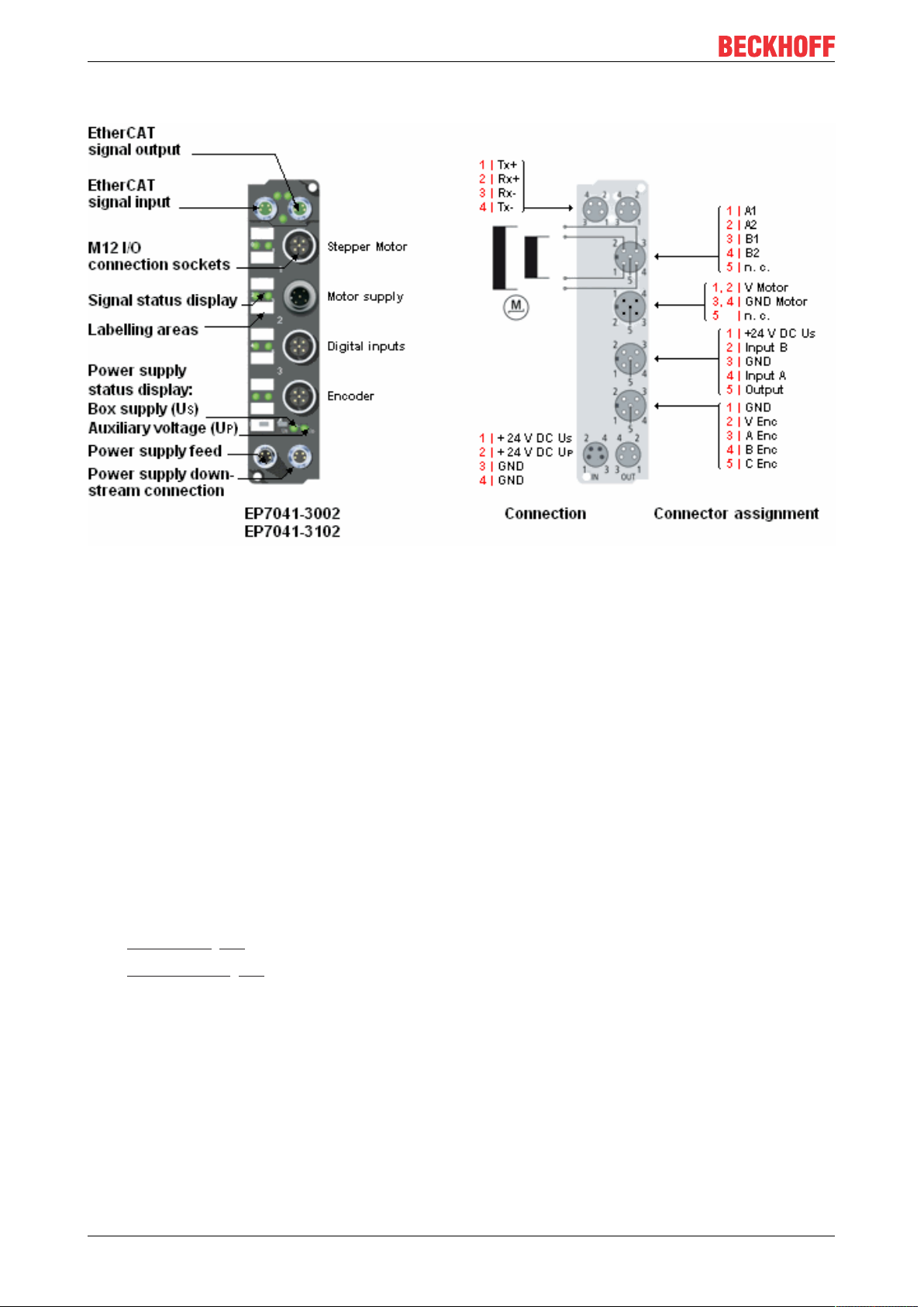
2.3.3 EP7041-3002, EP7041-3102
Fig.7: EP7041-3002 and EP7041-3102
Stepper Motor modules with interface for incremental encoder
The EP7041-3002 and EP7041-3102 EtherCAT Box Modules are designed for direct connection of different
stepper motors. The PWM output stages for two motor coils with compact design are located in the module
together with two inputs for limit switches and cover a wide voltage and current range.
A servo axis can easily be realized by connecting an incremental encoder. The modules supply the
incremental encoder with:
EP7041-3002: 24V
EP7041-3102: 5V
DC
DC
Two digital inputs and a digital output (0.5A) enable connection of limit switches and a motor brake.
The external motor is fed via an integrated plug.
EP7041-3002 and EP7041-3102 are designed for higher velocities and can be adjusted to the motor and the
application by changing various parameters.
Quick-Links
• Installation [}20]
• Configuration [}36]
EP704114 Version: 2.3
Page 15

Product overview
2.4 Technical data
All values are typical values at 25°C, unless otherwise stated.
Technical data EP7041-0002 EP7041-1002 EP7041-2002 EP7041-3002 EP7041-3102
Fieldbus
Fieldbus EtherCAT
Connection 2 x M8 socket, green
Electrical isolation 500V (fieldbus/ IO)
Process image Input: 2 x 16bit data, 1 x 16bit status
Supply voltages
Connection Feed: 1 x M8 plug, 4-pin
Control voltage U
S
Nominal voltage 24VDC (-15%/ +20%)
Sum current max. 4A
Consumers Module electronics: 120mA
Peripheral voltage U
Nominal voltage 24VDC (-15%/ +20%)
Sum current max. 4A
Consumers • Encoder
Motor
Motor type 2-phase stepper motor, unipolar or bipolar
Connection M12 socket
DC link voltage max. 50VDC, not protected against polarity reversal
Connection
Rated current per phase 3.5A 1.0A 3.5A
Peak current per phase 5.0A at 50°C 1.5A 5.0A at 50°C
Microstepping max. 64 microsteps
Step frequency max. 32,000 full steps per second (configurable)
Current controller frequency
Driver circuit 2x H-bridge
Protective functions Overload protection, short-circuit protection
Encoder input
encoder type Incremental encoder with single-ended output drivers:
Connection M12 socket
Signals A, B, C (reference pulse/zero pulse)
Low level -3.. 2V
High level 3.5.. 28V
Supply voltage 24VDC from peripheral voltage U
Supply current 0.5A, not short-circuit proof 0.3A
Pulse frequency maximum 400,000 increments/s (quadruple evaluation)
Output: 2 x 16bitdata, 1 x 16bit control
Downstream connection: 1 x M8 socket, 4-pin
1)
P
1)
• Digital output: Brake
M12 socket "2“ [}27] M12 connector "2“ [}27]
2)
approx. 30kHz
• Push-pull
• Open collector
DC
DC
3)
P
max. 256 microsteps
2)
max. 1VDC
2.5.. 28VDC
5V
DC
4)
4)
1)
Sum current of consumers and power transmission. This value corresponds to the
current carrying capacity of the connections for the supply voltages.
2)
EP7041 automatically selects the number of microsteps according to the speed
3)
Pull-up resistor required
4)
These levels apply from hardware version 09. Up to hardware version 08 the following levels apply:
• Low level: -3.. 2V
• High level: 3.5.. 28V
DC
DC
EP7041 15Version: 2.3
Page 16

Product overview
Technical data EP7041-0002 EP7041-1002 EP7041-2002 EP7041-3002 EP7041-3102
Digital inputs: limit switch
Number 2
Connection M12 socket
Signal voltage "0" -3V...2V
Signal voltage "1" 3.5V ...28V
Input current 5mA
Digital output: Brake
Number 1
Connection M12 socket
Output voltage 24VDC from peripheral voltage U
Output current 0.5A, short-circuit proof
Environmental conditions
Ambient temperature
during operation
Ambient temperature
during storage
Vibration/
shock resistance
EMC immunity/
emission
Protection class IP65, IP66, IP67 (conforms to EN 60529)
Mechanics
Dimensions approx. 126x 30x 26.5mm (without connectors)
Weight approx. 165g
Installation position up to 40°C ambient temperature: variable
Approvals and conformity
Approvals
-25 .. +60°C
0 .. +55°C according to ATEX, see special conditions [}30]
-40 .. +85°C
conforms to EN60068-2-6/ EN60068-2-27
conforms to EN61000-6-2/ EN61000-6-4
over 40°C ambient temperature: distance between 2 stepper motor modules at least 20mm
CE, ATEX [}30]
P
2.5 Scope of supply
Make sure that the following components are included in the scope of delivery:
• 1x EtherCAT Box EP7041
• 1x protective cap for supply voltage input, M8, transparent (pre-assembled)
• 1x protective cap for supply voltage output, M8, black (pre-assembled)
• 2x protective cap for EtherCAT socket, M8, green (pre-assembled)
• 10x labels, blank (1 strip of 10)
Pre-assembled protective caps do not ensure IP67 protection
Protective caps are pre-assembled at the factory to protect connectors during transport. They may
not be tight enough to ensure IP67 protection.
Ensure that the protective caps are correctly seated to ensure IP67 protection.
EP704116 Version: 2.3
Page 17

2.6 EP7041 - Process image
The TwinCAT System Manager displays the EP7041 data in a tree structure.
The tree shows
• ENC Status compact: encoder status
• STM Status: Stepper Motor Status
• ENC Control compact: Encoder Control
• STM Control: Stepper Motor Control
• STM Velocity: Stepper Motor Velocity
ENC Status compact
The status information for the encoder can be
found under ENC Status compact.
Product overview
EP7041 17Version: 2.3
Page 18

Product overview
STM Status
The status information for the stepper motor can
be found under STM Status.
ENC Control compact
STM Control
The control parameters for the encoder can be
found under ENC Control compact.
The control parameters for the stepper motor can
be found under STM Control.
EP704118 Version: 2.3
Page 19

STM Velocity
Product overview
The velocity settings for the stepper motor can be
found under STM Velocity.
EP7041 19Version: 2.3
Page 20

Installation
119
126
23
30
26.5
13.5
Ø 3.5
3 Installation
3.1 Mounting
3.1.1 Dimensions
Fig.8: Dimensions
All dimensions are given in millimeters.
Housing features
Housing material PA6 (polyamide)
Sealing compound polyurethane
Mounting two fastening holes Ø3.5mm for M3
Metal parts brass, nickel-plated
Contacts CuZn, gold-plated
Power feed through max. 4A
Mounting position variable
Protection class IP65, IP66, IP67 (conforms to EN60529) when screwed together
Dimensions (HxWxD) approx. 126 x 30 x 26.5mm (without connectors)
EP704120 Version: 2.3
Page 21

Installation
3.1.2 Fixing
NOTE
Dirt during assembly
Dirty plug connectors can lead to malfunctions. Protection class IP67 can only be guaranteed if all cables
and connectors are connected.
• Protect the plug connectors against dirt during the assembly.
Mount the module with two M3 screws on the fastening holes in the corners of the module. The fastening
holes have no thread.
3.1.3 Tightening torques for plug connectors
Screw connectors tight with a torque wrench. (e.g. ZB8801 from Beckhoff)
Connector diameter Tightening torque
M8 0.4Nm
M12 0.6Nm
EP7041 21Version: 2.3
Page 22

Installation
Plug
Feed-in
Socket
Forwarding
3 1
24
3 1
24
3.2 Connection
3.2.1 Supply voltages
The EtherCAT Box is supplied with two supply voltages. The ground potentials of the supply voltages are
galvanically connected together.
• Control voltage U
• Peripheral voltage U
S
P
Redirection of the supply voltages
The IN and OUT power connections are bridged in the module (not IP204x-Bxxx and IE204x). The supply
voltages US and UP can thus easily be transferred from EtherCATBox to EtherCATBox.
NOTE
Pay attention to the maximum permissible current!
Pay attention also for the redirection of the supply voltages US and UP, the maximum permissible current for
M8 connectors of 4A must not be exceeded!
3.2.1.1 Connector
NOTE
Risk of confusion: supply voltages and EtherCAT
Defect possible through incorrect insertion.
• Observe the color coding of the connectors:
black: Supply voltages
green: EtherCAT
Fig.9: Connectors for supply voltages
Fig.10: M8 connector
Contact Function Description Core color
1 U
2 U
3 GND
4 GND
1)
The core colors apply to cables of the type: Beckhoff ZK2020-xxxx-xxxx
S
P
S
P
Control voltage Brown
Peripheral voltage White
GND to U
GND to U
S
P
Blue
Black
1)
EP704122 Version: 2.3
Page 23

Installation
Vert. Faktor: 0,45 cm / V
5 10 15 20
2
4
6
8
10
250
0
12
30
Vert. Faktor: 0,45 cm / V
Voltage drop (V)
Cable length (m)
35
0,25 mm²
0,34 mm²
0,5 mm²
0,75 mm²
I = 2 A
Vert. Faktor: 0,45 cm / V
5 10 15 20
2
4
6
8
10
250
0
12
30
Vert. Faktor: 0,45 cm / V
Voltage drop (V)
Cable length (m)
35
0,25 mm²
0,34 mm²
0,5 mm²
0,75 mm²
I = 4 A
3.2.1.2 Status LEDs
Fig.11: Status LEDs for the power supply
LED Display Meaning
US (control voltage) off Supply voltage, US, is not present
green illuminated Supply voltage, US, is present
UP (peripheral voltage) off Supply voltage, UP, is not present
green illuminated Supply voltage, UP, is present
3.2.1.3 Conductor losses
Take into account the voltage drop on the supply line when planning a system. Avoid the voltage drop being
so high that the supply voltage at the box lies below the minimum nominal voltage.
Variations in the voltage of the power supply unit must also be taken into account.
Voltage drop on the supply line
EP7041 23Version: 2.3
Page 24

Installation
3 1
24
3.2.2 EtherCAT
3.2.2.1 Connector
EtherCAT Box Modules have two green M8 sockets for the incoming and downstream EtherCAT
connections.
Fig.12: EtherCAT connector
Connection
Fig.13: M8 socket
EtherCAT M8
Signal Contact ZB9010, ZB9020, ZB9030, ZB9032,
Tx + 1 yellow
Tx - 4 orange
Rx + 2 white
Rx - 3 blue
Shield Housing Shield Shield Shield
1)
Core colors according to EN61918
connector
Core colors
ZK1090-6292,
ZK1090-3xxx-xxxx
1)
1)
1)
1)
ZB9031 and old versions of
ZB9030, ZB9032, ZK1090-3xxxxxxx
orange/white white/orange
orange orange
blue/white white/green
blue green
TIA-568B
Adaptation of core colors for cables ZB9030, ZB9032 and ZK1090-3xxxx-xxxx
For standardization, the core colors of the ZB9030, ZB9032 and ZK1090-3xxx-xxxx cables have
been changed to the EN61918 core colors: yellow, orange, white, blue. So there are different color
codes in circulation. The electrical properties of the cables have been retained when the core colors
were changed.
EP704124 Version: 2.3
Page 25

Installation
3.2.2.2 Status LEDs
Fig.14: EtherCAT status LEDs
L/A (Link/Act)
A green LED labelled "L/A" is located next to each EtherCAT socket. The LED indicates the communication
state of the respective socket:
LED Meaning
off no connection to the connected EtherCAT device
lit LINK: connection to the connected EtherCAT device
flashes ACT: communication with the connected EtherCAT device
Run
Each EtherCAT slave has a green LED labelled "Run". The LED signals the status of the slave in the
EtherCAT network:
LED Meaning
off Slave is in "Init" state
flashes uniformly Slave is in "Pre-Operational“ state
flashes sporadically Slave is in "Safe-Operational" state
lit Slave is in "Operational" state
Description of the EtherCAT slave states
3.2.2.3 Cables
For connecting EtherCAT devices only shielded Ethernet cables that meet the requirements of at least
category5 (CAT5) according to EN50173 or ISO/IEC11801 should be used.
EtherCAT uses four wires for signal transmission.
Thanks to automatic line detection ("Auto MDI-X"), both symmetrical (1:1) or cross-over cables can be used
between Beckhoff EtherCAT.
Detailed recommendations for the cabling of EtherCAT devices
EP7041 25Version: 2.3
Page 26

Installation
3.2.3 Stepper motor, brake, encoder
3.2.3.1 Signal connection
Fig.15: Signal connection EP7041-3002
NOTE
Note the numbering of the M12 sockets
Mixing up the M12 connectors can damage the module.
M12 socket no.1: Stepper motor connection
Fig.16: Stepper motor connection
EP704126 Version: 2.3
Page 27

M12-Socket no.2: Connection for motor supply
NOTE
The motor supply connection is not protected against polarity reversal
Defect possible through polarity reversal.
• Ensure that the polarity is correct.
Fig.17: Connection for motor supply with EP7041-0002 [}12] and EP7041-1002 [}12]
Installation
Fig.18: Connection for motor supply with EP7041-2002 [}13] and EP7041-3002 [}14]
M12 socket no.3: Connection for digital inputs and outputs
The signal connection of the digital inputs and outputs is done via M12 connectors.
Fig.19: Connection for digital inputs and outputs
The sensors are supplied with a common maximum current of 0.5Afrom the control voltage Us.
The output is short-circuit-proof and is protected against polarity reversal.
LEDs indicate the signal state of the inputs and outputs.
EP7041 27Version: 2.3
Page 28

Installation
M12 socket no. 4: Encoder connection
NOTE
The encoder supply voltage is not short-circuit proof.
Risk of damage due to short circuit.
• Avoid short-circuiting the encoder supply voltage "V Enc“.
Encoder
Fig.20: Encoder connection
EP704128 Version: 2.3
Page 29

3.2.3.2 Status LEDs
Installation
Fig.21: LEDs EP7041-3002
Status LEDs at the M12 connections
Connection LED Display Meaning
M12 socket no.1:
Stepper motor
M12 socket no.2:
Motor supply
M12 socket no.3:
binary inputs
binary output
M12 socket no.4:
Encoder
S
left
R
right
V
left
O
right
DI 1
left
DI 2
right
C
left
A
right
green
yellow If motor is disabled: motor control in standby
red
green Motor is turning
red internal error
off Motor supply voltage is not present
green Motor supply voltage is present
off Binary output (M12 socket no.3, pin5) switched off (0V)
green Binary output (M12 socket no.3, pin5) switched on (24V)
off there is no signal (0V) on binary input1 (M12 socket no. 3, pin4)
green there is no signal (24V) on binary input1 (M12 socket no. 3, pin4)
off there is no signal (0V) on binary input 2 (M12 socket no. 3, pin2)
green there is no signal (24V) on binary input2 (M12 socket no. 3, pin2)
flashes Encoder track C
flashes Encoder trackA
Motor control is enabled (Index 0x6010:02 [}95] is set) and EP7041 is ready to operate
If motor is enabled: warning, configuration error. Check the motor status.
Error: Check DiagData (Index 0xA010 [}101])
EP7041 29Version: 2.3
Page 30

Installation
3.3 ATEX notes
3.3.1 ATEX - Special conditions
WARNING
Observe the special conditions for the intended use of EtherCAT Box modules in potentially explosive areas – directive 94/9/EU.
• The certified components are to be installed with a BG2000-0000 or BG2000-0010 protection enclosure
[}31] that guarantees a protection against mechanical hazards!
• If the temperatures during rated operation are higher than 70°C at the feed-in points of cables, lines or
pipes, or higher than 80°C at the wire branching points, then cables must be selected whose temperature data correspond to the actual measured temperature values!
• Observe the permissible ambient temperature range of 0 to 55°C for the use of EtherCAT Box modules
in potentially explosive areas!
• Measures must be taken to protect against the rated operating voltage being exceeded by more than
40% due to short-term interference voltages!
• The connections of the certified components may only be connected or disconnected if the supply voltage has been switched off or if a non-explosive atmosphere is ensured!
Standards
The fundamental health and safety requirements are fulfilled by compliance with the following standards:
• EN 60079-0: 2006
• EN 60079-15: 2005
Marking
The EtherCAT Box modules certified for potentially explosive areas bear the following marking:
II 3 GEx nA II T4DEKRA 11ATEX0080 XTa: 0 - 55°C
or
II 3 GEx nA nC IIC T4DEKRA 11ATEX0080 XTa: 0 - 55°C
Batch number (D number)
The EtherCAT Box modules bear a batch number (D number) that is structured as follows:
D: WW YY FF HH
WW - week of production (calendar week)
YY - year of production
FF - firmware version
HH - hardware version
Example with batch number 29 10 02 01:
29 - week of production 29
10 - year of production 2010
02 - firmware version 02
01 - hardware version 01
EP704130 Version: 2.3
Page 31

Installation
3.3.2 BG2000 - EtherCAT Box protection enclosures
WARNING
Risk of electric shock and damage of device!
Bring the EtherCAT system into a safe, powered down state before starting installation, disassembly or
wiring of the modules!
ATEX
WARNING
Mount a protection enclosure!
To fulfill the special conditions according to ATEX [}30], a BG2000-0000 or BG2000-0010 protection enclosure has to be mounted over the EtherCAT Box.
Installation
Put the cables for EtherCAT, power supply and sensors/actuators through the hole of the protection
enclosure.
Fig.22: BG2000 - putting the cables
Fix the wires for EtherCAT, power supply and sensors/actuators to the EtherCAT Box.
EP7041 31Version: 2.3
Page 32

Installation
Fig.23: BG2000 - fixing the cables
Mount the protection enclosure over the EtherCAT Box.
Fig.24: BG2000 - mounting the protection enclosure
3.3.3 ATEX Documentation
Notes about operation of EtherCAT Box Modules (EPxxxx-xxxx) in potentially explosive areas (ATEX)
Pay also attention to the continuative documentationNotes about operation of EtherCAT Box Modules (EPxxxx-xxxx) in potentially explosive areas (ATEX) that is available in the download area of
the Beckhoff homepage http:\\www.beckhoff.com!
EP704132 Version: 2.3
Page 33

Commissioning/Configuration
4 Commissioning/Configuration
4.1 Integration in TwinCAT
4.1.1 Inserting into the EtherCAT network
Installation of the latest XML device description
Please ensure that you have installed the latest XML device description in TwinCAT. This can be
downloaded from the Beckhoff website (http://www.beckhoff.de/english/download/elconfg.htm?
id=1983920606140) and installed according to the installation instructions.
At the Beckhoff TwinCAT System Manager the configuration tree can be build in two different ways:
• by scanning [}33] for existing hardware (called "online") and
• by manual inserting/appending [}33] of fieldbus devices, couplers and slaves.
Automatic scanning in of the box
• The EtherCAT system must be in a safe, de-energized state before the EtherCAT modules are
connected to the EtherCAT network!
• Switch on the operating voltage, open the TwinCAT System Manager [}36] (Config mode), and scan
in the devices (see Fig. 1). Acknowledge all dialogs with "OK", so that the configuration is in "FreeRun"
mode.
Fig.25: Scanning in the configuration (I/O Devices -> right-click -> Scan Devices...)
Appending a module manually
• The EtherCAT system must be in a safe, de-energized state before the EtherCAT modules are
connected to the EtherCAT network!
• Switch on the operating voltage, open the TwinCAT System Manager [}36] (Config mode)
• Append a new I/O device. In the dialog that appears select the device EtherCAT (Direct Mode), and
confirm with OK.
EP7041 33Version: 2.3
Page 34

Commissioning/Configuration
Fig.26: Appending a new I/O device (I/O Devices -> right-click -> Append Device...)
Fig.27: Selecting the device EtherCAT
• Append a new box.
Fig.28: Appending a new box (Device -> right-click -> Append Box...)
• In the dialog that appears select the desired box (e.g. EP2816-0008), and confirm with OK.
EP704134 Version: 2.3
Page 35

Commissioning/Configuration
Fig.29: Selecting a Box (e.g. EP2816-0008)
Fig.30: Appended Box in the TwinCAT tree
EP7041 35Version: 2.3
Page 36

Commissioning/Configuration
4.1.2 Configuration via TwinCAT
In the left-hand window of the TwinCAT System Manager, click on the branch of the EtherCAT Box you wish
to configure (EP2816-0008 in this example).
Fig.31: Branch of the EtherCAT box to be configured
In the right-hand window of the TwinCAT System manager, various tabs are now available for configuring
the EtherCAT Box.
General tab
Fig.32: General tab
Name Name of the EtherCAT device
Id Number of the EtherCAT device
Type EtherCAT device type
Comment Here you can add a comment (e.g. regarding the system).
Disabled Here you can deactivate the EtherCAT device.
Create symbols Access to this EtherCAT slave via ADS is only available if this checkbox is
activated.
EP704136 Version: 2.3
Page 37

Commissioning/Configuration
EtherCAT tab
Fig.33: EtherCAT tab
Type EtherCAT device type
Product/Revision Product and revision number of the EtherCAT device
Auto Inc Addr. Auto increment address of the EtherCAT device. The auto increment address can
be used for addressing each EtherCAT device in the communication ring through
its physical position. Auto increment addressing is used during the start-up phase
when the EtherCAT master allocates addresses to the EtherCAT devices. With
auto increment addressing the first EtherCAT slave in the ring has the address
0000
. For each further slave the address is decremented by 1 (FFFF
hex
, FFFE
hex
etc.).
EtherCAT Addr. Fixed address of an EtherCAT slave. This address is allocated by the EtherCAT
master during the start-up phase. Tick the checkbox to the left of the input field in
order to modify the default value.
Previous Port Name and port of the EtherCAT device to which this device is connected. If it is
possible to connect this device with another one without changing the order of the
EtherCAT devices in the communication ring, then this combobox is activated and
the EtherCAT device to which this device is to be connected can be selected.
Advanced Settings This button opens the dialogs for advanced settings.
hex
The link at the bottom of the tab points to the product page for this EtherCAT device on the web.
Process Data tab
Indicates the configuration of the process data. The input and output data of the EtherCAT slave are
represented as CANopen process data objects (PDO). The user can select a PDO via PDO assignment and
modify the content of the individual PDO via this dialog, if the EtherCAT slave supports this function.
EP7041 37Version: 2.3
Page 38

Commissioning/Configuration
Fig.34: Process Data tab
Sync Manager
Lists the configuration of the Sync Manager (SM).
If the EtherCAT device has a mailbox, SM0 is used for the mailbox output (MbxOut) and SM1 for the mailbox
input (MbxIn).
SM2 is used for the output process data (outputs) and SM3 (inputs) for the input process data.
If an input is selected, the corresponding PDO assignment is displayed in the PDO Assignment list below.
PDO Assignment
PDO assignment of the selected Sync Manager. All PDOs defined for this Sync Manager type are listed
here:
• If the output Sync Manager (outputs) is selected in the Sync Manager list, all RxPDOs are displayed.
• If the input Sync Manager (inputs) is selected in the Sync Manager list, all TxPDOs are displayed.
The selected entries are the PDOs involved in the process data transfer. In the tree diagram of the System
Manager these PDOs are displayed as variables of the EtherCAT device. The name of the variable is
identical to the Name parameter of the PDO, as displayed in the PDO list. If an entry in the PDO assignment
list is deactivated (not selected and greyed out), this indicates that the input is excluded from the PDO
assignment. In order to be able do select a greyed out PDO, the currently selected PDO has to be
deselected first.
EP704138 Version: 2.3
Page 39

Commissioning/Configuration
Activation of PDO assignment
• the EtherCAT slave has to run through the PS status transition cycle (from pre-operational to
safe-operational) once (see Online tab [}42]),
• and the System Manager has to reload the EtherCAT slaves ( button)
PDO list
List of all PDOs supported by this EtherCAT device. The content of the selected PDOs is displayed in the
PDO Content list. The PDO configuration can be modified by double-clicking on an entry.
Column Description
Index PDO index.
Size Size of the PDO in bytes.
Name Name of the PDO.
If this PDO is assigned to a Sync Manager, it appears as a variable of the slave with this
parameter as the name.
Flags F Fixed content: The content of this PDO is fixed and cannot be changed by the System
Manager.
M Mandatory PDO. This PDO is mandatory and must therefore be assigned to a Sync Manager!
Consequently, this PDO cannot be deleted from the PDO Assignment list
SM Sync Manager to which this PDO is assigned. If this entry is empty, this PDO does not take part in
the process data traffic.
SU Sync unit to which this PDO is assigned.
PDO Content
Indicates the content of the PDO. If flag F (fixed content) of the PDO is not set the content can be modified.
Download
If the device is intelligent and has a mailbox, the configuration of the PDO and the PDO assignments can be
downloaded to the device. This is an optional feature that is not supported by all EtherCAT slaves.
PDO Assignment
If this check box is selected, the PDO assignment that is configured in the PDO Assignment list is
downloaded to the device on startup. The required commands to be sent to the device can be viewed in the
Startup [}39] tab.
PDO Configuration
If this check box is selected, the configuration of the respective PDOs (as shown in the PDO list and the
PDO Content display) is downloaded to the EtherCAT slave.
Startup tab
The Startup tab is displayed if the EtherCAT slave has a mailbox and supports the CANopen over EtherCAT
(CoE) or Servo drive over EtherCAT protocol. This tab indicates which download requests are sent to the
mailbox during startup. It is also possible to add new mailbox requests to the list display. The download
requests are sent to the slave in the same order as they are shown in the list.
EP7041 39Version: 2.3
Page 40

Commissioning/Configuration
Fig.35: Startup tab
Column Description
Transition Transition to which the request is sent. This can either be
• the transition from pre-operational to safe-operational (PS), or
• the transition from safe-operational to operational (SO).
If the transition is enclosed in "<>" (e.g. <PS>), the mailbox request is fixed and cannot be
modified or deleted by the user.
Protocol Type of mailbox protocol
Index Index of the object
Data Date on which this object is to be downloaded.
Comment Description of the request to be sent to the mailbox
Move Up This button moves the selected request up by one position in the list.
Move Down This button moves the selected request down by one position in the list.
New This button adds a new mailbox download request to be sent during startup.
Delete This button deletes the selected entry.
Edit This button edits an existing request.
CoE - Online tab
The additional CoE - Online tab is displayed if the EtherCAT slave supports the CANopen over EtherCAT
(CoE) protocol. This dialog lists the content of the object directory of the slave (SDO upload) and enables the
user to modify the content of an object from this list. Details for the objects of the individual EtherCAT
devices can be found in the device-specific object descriptions.
EP704140 Version: 2.3
Page 41

Commissioning/Configuration
Fig.36: CoE - Online tab
Object list display
Column Description
Index Index and subindex of the object
Name Name of the object
Flags RW The object can be read, and data can be written to the object (read/write)
RO The object can be read, but no data can be written to the object (read only)
P An additional P identifies the object as a process data object.
Value Value of the object
Update List The Update list button updates all objects in the displayed list
Auto Update If this check box is selected, the content of the objects is updated automatically.
Advanced The Advanced button opens the Advanced Settings dialog. Here you can specify which
objects are displayed in the list.
EP7041 41Version: 2.3
Page 42

Commissioning/Configuration
Fig.37: Advanced settings
Online
- via SDO information
Offline
- via EDS file
Online tab
If this option button is selected, the list of the objects included in the object
directory of the slave is uploaded from the slave via SDO information. The list
below can be used to specify which object types are to be uploaded.
If this option button is selected, the list of the objects included in the object
directory is read from an EDS file provided by the user.
Fig.38: Online tab
EP704142 Version: 2.3
Page 43

Commissioning/Configuration
State Machine
Init This button attempts to set the EtherCAT device to the Init state.
Pre-Op This button attempts to set the EtherCAT device to the pre-operational state.
Op This button attempts to set the EtherCAT device to the operational state.
Bootstrap This button attempts to set the EtherCAT device to the Bootstrap state.
Safe-Op This button attempts to set the EtherCAT device to the safe-operational state.
Clear Error This button attempts to delete the fault display. If an EtherCAT slave fails during
change of state it sets an error flag.
Example: An EtherCAT slave is in PREOP state (pre-operational). The master now
requests the SAFEOP state (safe-operational). If the slave fails during change of
state it sets the error flag. The current state is now displayed as ERR PREOP. When
the Clear Error button is pressed the error flag is cleared, and the current state is
displayed as PREOP again.
Current State Indicates the current state of the EtherCAT device.
Requested State Indicates the state requested for the EtherCAT device.
DLL Status
Indicates the DLL status (data link layer status) of the individual ports of the EtherCAT slave. The DLL status
can have four different states:
Status Description
No Carrier / Open No carrier signal is available at the port, but the port is open.
No Carrier / Closed No carrier signal is available at the port, and the port is closed.
Carrier / Open A carrier signal is available at the port, and the port is open.
Carrier / Closed A carrier signal is available at the port, but the port is closed.
File Access over EtherCAT
Download With this button a file can be written to the EtherCAT device.
Upload With this button a file can be read from the EtherCAT device.
EP7041 43Version: 2.3
Page 44

Commissioning/Configuration
4.1.3 Integration into the NC configuration
(Master: TwinCAT 2.11)
Installation of the latest XML device description
Please ensure that you have installed the corresponding latest XML device description in TwinCAT.
This can be downloaded from the Beckhoff website (http://www.beckhoff.de/german/default.htm?
download/elconfg.htm) and installed according to the installation instructions.
Integration into the NC can be accomplished as follows:
• The terminal must already have been inserted manually under I/O devices or have been scanned in by
the system (see section "Inserting the terminal in the EtherCAT Terminal network").
• First add a new task. Right-click on NC configuration and select "Append Task..." (see Fig. Adding a
new task).
• Rename the task if required and confirm with OK.
Fig.39: Adding a new task
• Right-click on Axes, then add a new axis (see Fig. Linking the axis with the terminal).
Fig.40: Adding a new axis
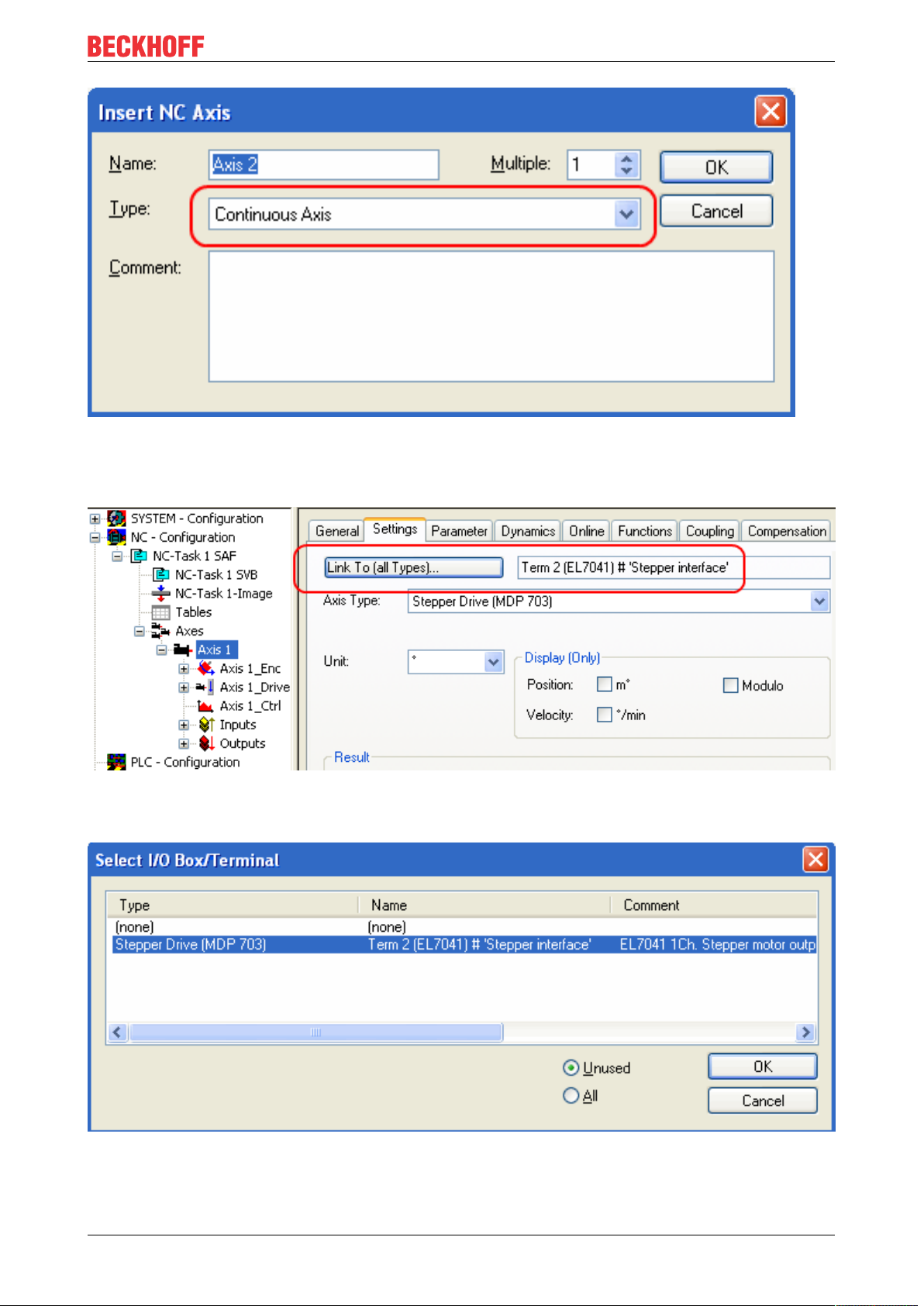
• Select Continuous Axis type and confirm with OK (see Fig. 3).
EP704144 Version: 2.3
Page 45
Commissioning/Configuration
Fig.41: Selecting and confirming the axis type
• Left-click your axis to select it. Under the Settings tab select "Link To..." (see Fig. Linking the axis with
the terminal).
Fig.42: Linking the axis with the terminal
• Select the right terminal (Stepper Drive (MDP 703)) and confirm with OK.
Fig.43: Selecting the right terminal
• All main links between the NC configuration and the terminal are set automatically (see Fig. "Automatic
linking of all main variables")
EP7041 45Version: 2.3
Page 46

Commissioning/Configuration
Fig.44: Automatic linking of all main variables
• Several parameters have to be set before the motor can be started up. The values can be found in
section "Configuration of the main parameters [}48]". Please set these parameters before continuing
with the motor commissioning procedure.
Commissioning the motor with the NC
• Once the parameters are set, the motor is basically ready for operation. Individual further parameters
have to be adapted to the respective application.
• To commission the axis, activate the configuration (Ctrl+Shift+F4), select the axis, select tab Online
and enable the axis under Set.
• Set all check marks and set Override to 100 (see Fig. 7). The axis can then be moved.
EP704146 Version: 2.3
Page 47

Commissioning/Configuration
Fig.45: Enabling an axis
You can now move the axis with the function keys F1, F2 (Backward) or F3, F4 (Forward).
Alternatively you can control the axis via the Functions tab.
Example
• Select as Reversing Sequence as the start mode.
• Enter the required Target Position1, e.g. 5000°.
• Enter the required Target Velocity, e.g. 1200°/s.
• Enter the required Target Position2, e.g. 0°.
• Enter the required Idle Time, e.g. 1 s.
• Select Start.
EP7041 47Version: 2.3
Page 48

Commissioning/Configuration
Fig.46: Axis control, "Functions" tab
The motor now travels to Position1, remains there for 1s and then returns to Position2. This is repeated
until you click Stop.
4.1.4 Configuration of the main parameters
The data specified here apply to an AS 1050-0120 stepper motor and are intended as an example. For other
motors the values may vary, depending on the application.
Setting the CoE objects
Execution of changes
Changes to CoE objects are only executed after the module has been placed in the Init state.
Changes are only active after that.
Adaptation of current and voltage
NOTE
The motor may overheat!
In order to prevent overheating of the connected motor it is important to adapt the current and voltage output from the stepper interface to the motor.
To do this, set the indices 0x8010:01 [}78] Maximal current and 0x8010:03 [}78]Nominal voltage in the
CoE register to suitable values (see Fig. Adaptation of current and voltage).
EP704148 Version: 2.3
Page 49

Commissioning/Configuration
Reduced current can be set in index 0x8010:02 [}78]. This reduces the coil current when at a standstill
(and therefore the power dissipation). Please note that the torque is also reduced.
Fig.47: Adaptation of current and voltage
Base frequency selection
Microstepping is set to 1/64 and cannot be changed. However, the base frequency can be changed (default:
2000). To do this, mark the module and select the CoE Online tab. Change the base frequency by doubleclicking on the index 0x8012:05 [}79] Speedrange (Fig. Setting the base frequency).
Fig.48: Setting the base frequency
Selecting the feedback system
The module with encoder connections provides a choice of two possibilities for the feedback system:
• Internal Counter (default): Use internal counter for position feedback
• Encoder: Use external encoder for position feedback
EP7041 49Version: 2.3
Page 50

Commissioning/Configuration
Setting the feedback type
By default, the stepper module is set to internal counter. If an external encoder is used, the setting
must be changed by double-clicking on the index 0x8012:08 [}79] Feedback type in the Enum
menu (Fig. Selecting the feedback system).
Fig.49: Selecting the feedback system
KA factor (EP7041-0002 [}12] and EP7041-1002 [}12]only)
The KA factor can be used to adapt the current during the acceleration phases. The current increase is
calculated as follows.
Current increaseinmA=speed differencexKA/1000
The steeper the speed ramp, the higher the current increase.
EP704150 Version: 2.3
Page 51

Commissioning/Configuration
Fig.50: Speed ramps
This value can be set in index 0x8011:07 [}78] Ka factor (curr.) (see fig. Setting the KA factor).
Fig.51: Setting the KA factor
NC settings
Reference speed selection
The maximum speed can be calculated from the base frequency and the motor frequency.
v
=basefrequency/motorfrequency=(2000fullsteps/s)/(200fullsteps/rev)=10revolutions/s
max
The reference speed can be calculated by multiplying the maximum speed with the distance per revolution.
v
=10revolutions/sx360°=3600°/s
ref
EP7041 51Version: 2.3
Page 52

Commissioning/Configuration
Fig.52: Reference speed parameter
Dead time compensation
The dead time compensation should theoretically be 3cycles of the NC cycle time, although in practice
4cycles are preferable. At a cycle time of 2ms it should therefore be 0.008s. The dead time compensation
can be found under Advanced Settings in the encoder parameters.
Fig.53: Dead time compensation parameter
Scaling factor
The scaling factor can be changed by selecting NC Axis 1_Enc and the Parameter tab in the NC (see fig.
Setting the scaling factor (example with encoder)). The value can be calculated with the formulas specified
below.
EP704152 Version: 2.3
Page 53

Commissioning/Configuration
Fig.54: Setting the scaling factor (example with encoder)
Calculation of the scaling factor
with encoder:
SF=distance per revolution/incrementsx4=360°/1024x4=0.087890625mm/INC
without encoder:
SF=distanceperrevolution/fullstepsxmicrosteps=360°/200x64=0.028125mm/INC
Position lag monitoring
The position lag monitoring function checks whether the current position lag of an axis has exceeded the
limit value. The position lag is the difference between the set value (control value) and the actual value
reported back. If the terminal parameters are set inadequately, the position lag monitoring function may
report an error when the axis is moved. During commissioning it may therefore be advisable to increase the
limits of the Position lag monitoring slightly.
NOTE
ATTENTION: Damage to equipment, machines and peripheral components possible!
Setting the position lag monitoring parameters too high may result in damage to equipment, machines and
peripheral components.
EP7041 53Version: 2.3
Page 54

Commissioning/Configuration
Fig.55: Position lag monitoring parameters
Kv factors (only with external encoder)
In the NC two proportional factors Kv can be set under Axis 1_Ctrl on the Parameter tab. First select the
position controller Type with two P constants (with KA) under the NC Controller tab. The two P constants are
for the Standstill range and for the Moving range (see Fig. Setting the proportional factor KV). The factors can
be used to set the start-up torque and the braking torque to a different value than the drive torque. The
threshold value can be set directly below (Position control: Velocity threshold V dyn) between 0.0 (0%) and
1.0 (100%). Fig. Velocity ramp with KV factor limit values shows a speed ramp with thresholds of 30%. The
Kv factor for Standstill (t1 and t3) can be different than the Kv factor for Moving (t2). In this case the same
factor was used, since for stepper motors this function is less crucial than for DC motors.
Fig.56: Speed ramp with KV factor limit values
EP704154 Version: 2.3
Page 55

Commissioning/Configuration
Fig.57: Setting the proportional factor K
V
Dead band for position errors
Microstepping can be used to target 200x64=12800positions. Since the encoder can only scan
1024x4=4096positions, positions between two encoder scan points may not be picked up correctly, in
which case the terminal will control around this position. The dead band for position errors is a tolerance
range within which the position is regarded as "reached" (Fig. Dead band for position errors).
Fig.58: Dead band for position errors
Setting the acceleration time
In order to pass through any resonances that may occur as quickly as possible, the ramps for the
acceleration time and the deceleration time should be as steep as possible.
EP7041 55Version: 2.3
Page 56

Commissioning/Configuration
Fig.59: Setting the acceleration time
4.1.5 Basic principles for the Positioning Interface
The Positioning interface offers the user a possibility to implement travel commands directly on the terminal.
4.1.5.1 Predefined PDO Assignment
The "Predefined PDO Assignment" enables a simplified selection of the process data. Select the function
"Positioning interface" or "Positioning interface compact" in the lower part of the Process data tab. As a
result, all necessary PDOs are automatically activated and the unnecessary PDOs are deactivated.
Fig.60: Predefined PDO Assignment
4.1.5.2 Parameter set
Two objects are at the user’s disposal in the CoE for the configuration – the "POS Settings" (Index 0x8020)
and the "POS Features" (Index 0x8021).
EP704156 Version: 2.3
Page 57

Commissioning/Configuration
Fig.61: Settings objects in the CoE
POS Settings: Velocity min.:
For reasons of performance when ramping down to the target position, the terminal needs a safety margin of
0.5%. That means that, depending on the maximum velocity reached and the configured deceleration, the
time is calculated at which the deceleration ramp begins. In order to always reach the destination reliably,
0.5% is subtracted from the position determined. If the deceleration ramp has ended and the destination has
not yet been reached, the terminal drives at the velocity “Velocity min.” to the destination. It must be
configured in such a way that the motor is able to stop abruptly and without a step loss at this velocity.
Velocity max.:
The maximum velocity with which the motor drives during a travel command
"Speed range" (index 0x8012:05) [applies to EL70x1]
Velocity min./max. are standardized to the configured "Speed range" (Index 0x8012:05). This
means that for a "Speed range" of 4000 full steps/second, for example, for a speed output of 100%
(i.e. 4000 full steps/second) 10,000 should be entered under "Velocity max.", and 5,000 for 50%
(i.e. 2000 full steps/second).
Acceleration pos.:
Acceleration time in the positive direction of rotation.
The 5 parameters for acceleration also refer to the set “Speed range” and are given in ms. With a setting of
1000, the terminal accelerates the motor from 0 to 100% in 1000 ms. At a speed of 50% the acceleration
time is linearly reduced to half accordingly.
Acceleration neg.:
Acceleration time in the negative direction of rotation.
Deceleration pos.:
Deceleration time in the positive direction of rotation.
Deceleration neg.:
Deceleration time in the negative direction of rotation.
EP7041 57Version: 2.3
Page 58

Commissioning/Configuration
Emergency deceleration:
Emergency deceleration time (both directions of rotation). If “Emergency stop” is set in the appropriate PDO,
the motor is stopped within this time.
Calibration position:
The current counter value is loaded with this value after calibration.
Calibration velocity (towards plc cam):
Velocity with which the motor travels towards the cam during calibration.
Calibration velocity (off plc cam):
Velocity with which the motor travels away from the cam during calibration.
Target window:
Target window of the travel distance control. "In-Target" is set if the motor comes to a stop within this target
window.
In-Target timeout:
"In-Target" is not set if the motor is not within the target window after the expiry of the travel distance control
after this set time. This condition can be recognized only by checking the falling edge of “Busy”.
Dead time compensation:
Compensation of the internal propagation delays. This parameter does not have to be changed with
standard applications.
Modulo factor:
The “Modulo factor” is referred to for the calculation of the target position and the direction of rotation in the
modulo operating modes. It refers to the controlled system.
Modulo tolerance window:
Tolerance window for the determination of the start condition of the modulo operating modes.
POS Features:
Start type:
The "Start type" specifies the type of calculation used to determine the target position (see below).
Time information:
The meaning of the "Actual drive time" displayed is configured by this parameter. At present this value
cannot be changed, since there are no further selection options. The elapsed time of the travel command is
displayed.
Invert calibration cam search direction:
In relation to a positive direction of rotation, the direction of the search for the calibration cam is configured
here (travel towards the cam).
Invert sync impulse search direction:
In relation to a positive direction of rotation, the direction of the search is configured here in accordance with
the HW sync pulse (travel away from the cam).
4.1.5.3 Information and diagnostic data
Via the information and diagnostic data, the user can obtain a more exact statement about which error
occurred during a travel command.
EP704158 Version: 2.3
Page 59

Commissioning/Configuration
Fig.62: Diagnostic objects in the CoE
POS Info data:
Status word:
The "Status word" reflects the status bits used in Index 0xA020 in a data word, in order to be able to process
them more simply in the PLC. The positions of the bits correspond to the number of the subindex-1.
Bit 0: Command rejected
Bit 1: Command aborded
Bit 2: Target overrun
State (drive controller):
The current status of the internal state machine is displayed here (see below).
POS Diag data:
Command rejected:
A dynamic change of the target position is not accepted each time by the terminal, since this is then not
possible. The new command is rejected in this case and indicated by the setting of this bit.
These 3 diagnostic bits are transmitted synchronously to the controller by setting “Warning” in the PDO.
Command aborted:
The current travel command was prematurely aborted due to an internal error or by an "Emergency stop".
Target overrun:
In the case of a dynamic change of the target position, the change may take place at a relatively late point in
time. The consequence of this may be that a change in the direction of rotation is necessary and that the
new target position may be overrun. “Target overrun” is set if this occurs.
4.1.5.4 States of the internal state machine
The state (drive controller) (Index 0x9020:03) provides information about the current state of the internal
state machine. For diagnostic purposes this can be read out by the PLC for the propagation delay. The
internal cycle works constantly with 250 µs. A connected PLC cycle is very probably slower (e.g. 1 ms). For
this reason it may be the case that some states are not visible at all in the PLC, since these will sometimes
run through only one internal cycle.
EP7041 59Version: 2.3
Page 60

Commissioning/Configuration
Name ID Description
INIT 0x0000 Initialization/preparation for the next travel command.
IDLE 0x0001 Wait for the next travel command.
START 0x0010 The new command is evaluated and the corresponding calculations are
performed.
ACCEL 0x0011 Acceleration phase.
CONST 0x0012 Constant phase
DECEL 0x0013 Deceleration phase
EMCY 0x0020 An "Emergency stop" has been triggered.
STOP 0x0021 The motor has stopped.
CALI_START 0x0100 Start of a calibration command.
CALI_GO_CAM 0x0110 The motor is being driven towards the cam.
CALI_ON_CAM 0x0111 The cam has been reached.
CALI_GO_SYNC 0x0120 The motor is being driven in the direction of the HW sync pulse.
CALI_LEAVE_CAM0x0121 The motor is being driven away from the cam.
CALI_STOP 0x0130 End of the calibration phase.
CALIBRATED 0x0140 The motor is calibrated.
NOT_CALIBRATED0x0141 The motor is not calibrated.
PRE_TARGET 0x1000 The set position has been reached; the position controller "pulls" the motor
further into the target; "In-Target timeout" is started here.
TARGET 0x1001 The motor has reached the target window within the timeout.
TARGET_RESTART0x1002 A dynamic change of the target position is processed here.
END 0x2000 End of the positioning phase.
WARNING 0x4000 A warning state occurred during the travel command; this is processed here.
ERROR 0x8000 An error state occurred during the travel command; this is processed here.
UNDEFINED 0xFFFF Undefined state (can occur, for example, if the driver stage has no control
voltage).
Table 1: States of the internal state machine
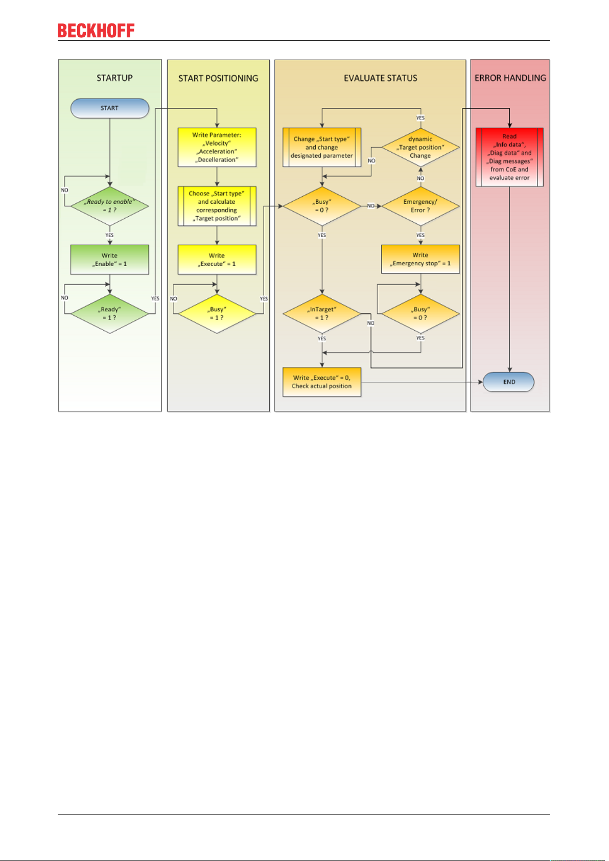
4.1.5.5 Standard sequence of a travel command
The “normally” sequence of a travel command is shown in the following flow diagram.
Coarse distinction is made between these four stages:
Startup
Test the system and the ready status of the motor.
Start positioning
Write all variables and calculate the desired target position with the appropriate “Start type”. Subsequently,
start the travel command.
Evaluate status
Monitor the terminal state and, if necessary, dynamically change the target position.
Error handling
In case of error, procure the necessary information from the CoE and evaluate it.
EP704160 Version: 2.3
Page 61
Commissioning/Configuration
Fig.63: Flow diagram for a travel command
4.1.5.6 Start types
The Positioning interface offers different types of positioning. The following table contains all commands
supported; these are divided into 4 groups.
EP7041 61Version: 2.3
Page 62

Commissioning/Configuration
Name Command Group Description
ABSOLUTE 0x0001
RELATIVE 0x0002 Relative positioning to a calculated target position; a specified posi-
ENDLESS_PLUS 0x0003 Endless travel in the positive direction of rotation (direct specification
ENDLESS_MINUS 0x0004 Endless travel in the negative direction of rotation (direct specifica-
ADDITIVE 0x0006 Additive positioning to a calculated target position; a specified posi-
ABSOLUTE_CHANGE 0x1001
RELATIVE_CHANGE 0x1002 Dynamic change of the target position during a travel command to a
ADDITIVE_CHANGE 0x1006 Dynamic change of the target position during a travel command to a
MODULO_SHORT 0x0105
MODULO_SHORT_EXT 0x0115 Modulo positioning along the shortest path to the modulo position;
MODULO_PLUS 0x0205 Modulo positioning in the positive direction of rotation to the calcu-
MODULO_PLUS_EXT 0x0215 Modulo positioning in the positive direction of rotation to the calcu-
MODULO_MINUS 0x0305 Modulo positioning in the negative direction of rotation to the calcu-
MODULO_MINUS_EXT 0x0315 Modulo positioning in the negative direction of rotation to the calcu-
MODULO_CURRENT 0x0405 Modulo positioning in the last direction of rotation to the calculated
MODULO_CURRENT_EXT 0x0415 Modulo positioning in the last direction of rotation to the calculated
CALI_PLC_CAM 0x6000
CALI_HW_SYNC 0x6100 Start a calibration with cam and HW sync pulse (C-track)
SET_CALIBRATION 0x6E00 Manually set the terminal to "Calibrated"
SET_CALIBRATION_AUTO 0x6E01 Automatically set the terminal to "Calibrated" on the first rising edge
CLEAR_CALIBRATION 0x6F00 Manually delete the calibration
Standard [}62]
Standard Ext.
[}63]
Modulo [}65]
Calibration [}64]
Absolute positioning to a specified target position
tion difference is added to the current position
of a speed)
tion of a speed)
tion difference is added to the last target position
Dynamic change of the target position during a travel command to a
new absolute position
new relative position (the current changing position value is used
here also)
new additive position (the last target position is used here)
Modulo positioning along the shortest path to the modulo position
(positive or negative), calculated by the "Modulo factor" (Index
0x8020:0E)
the "Modulo tolerance window" (Index 0x8020:0F) is ignored
lated modulo position
lated modulo position; the "Modulo tolerance window" is ignored
lated modulo position
lated modulo position; the "Modulo tolerance window" is ignored
modulo position
modulo position; the "Modulo tolerance window" is ignored
Start a calibration with cam (digital inputs)
on "Enable"
Table 2: Supported “Start types” of the “Positioning interface”
ABSOLUTE
The absolute positioning represents the simplest positioning case. A position B is specified and travelled to
from the start point A.
Fig.64: Absolute positioning
RELATIVE
In relative positioning, the user specifies a position delta S, which is added to the current position A,
producing the target position B.
EP704162 Version: 2.3
Page 63

Commissioning/Configuration
Fig.65: Relative positioning
ENDLESS_PLUS / ENDLESS_MINUS
The two start types ENDLESS_PLUS and ENDLESS_MINUS offer the possibility in the Positioning Interface
to specify a direct motor velocity in order to travel endlessly in the positive or negative direction with the
specified accelerations.
Fig.66: Endless travel
ADDITIVE
For additive positioning, the position delta S specified by the user is added to the target position E used for
the last travel command in order to calculate the target position B.
This kind of positioning resembles the relative positioning, but there is a difference. If the last travel
command was completed successfully, the new target position is the same. If there was an error, however,
be it that the motor entered a stall state or an Emergency stop was triggered, the current position is arbitrary
and not foreseeable. The user now has the advantage that he can use the last target position for the
calculation of the following target position.
Fig.67: Additive positioning
ABSOLUTE_CHANGE / RELATIVE_CHANGE / ADDITIVE_CHANGE
These three kinds of positioning are completely identical to those described above. The important difference
thereby is that the user uses these commands during an active travel command in order to dynamically
specify a new target position.
The same rules and conditions apply as to the “normal” start types. ABSOLUTE_CHANGE and
ADDITIVE_CHANGE are unique in the calculation of the target position i.e. in absolute positioning an
absolute position is specified and in additive positioning a position delta is added to the momentarily active
target position.
EP7041 63Version: 2.3
Page 64

Commissioning/Configuration
NOTE
Caution when using the RELATIVE_CHANGE positioning
The change by means of RELATIVE_CHANGE must be used with caution, since the current position of the
motor is also used here as the start position. Due to propagation delays in the system, the position indicated in the PDO never corresponds to the actual position of the motor! Therefore a difference to the desired target position always results in the calculation of the transferred position delta.
Time of the change of the target position
A change of the target position cannot take place at an arbitrary point in time. If the calculation of
the output parameters shows that the new target position cannot be readily reached, the command
is rejected by the terminal and the Command rejected [}58] bit is set. This is the case, for example,
at standstill (since the terminal expects a standard positioning here) and in the acceleration phase
(since at this point the braking time cannot be calculated yet).
CALI_PLC_CAM/ CALI_HW_SYNC/ SET_CALIBRATION/ SET_CALIBRATION_AUTO/
CLEAR_CALIBRATION:
The simplest calibration case is calibration by cam only (connected to one digital input).
Here, the motor travels in the 1st step with velocity 1 (Index 0x8020:09) in direction 1 (Index 0x8021:13)
towards the cam. Subsequently, in the 2nd step, it travels with velocity 2 (Index 0x8020:0A) in direction 2
(Index 0x8021:14) away from the cam. After the In-Target timeout"(Index 0x8020:0C) has elapsed, the
calibration position (Index 0x8020:08) is taken on by the terminal as the current position.
NOTE
Observe the switching hysteresis of the cam switch
With this simple calibration it must be noted that the position detection of the cam is only exact to a certain
degree. The digital inputs are not interrupt-controlled and are "only" polled. The internal propagation delays
may therefore result in a system-related position difference.
Fig.68: Calibration with cam
For a more precise calibration, an HW sync pulse (C-track) is used in addition to the cam. This calibration
proceeds in exactly the same way as described above, up to the point at which the motor travels away from
the cam. The travel is not stopped immediately; instead, the sync pulse is awaited. Subsequently, the In-
Target timeout runs down again and the calibration position is taken on by the terminal as the current
position.
Fig.69: Calibration with cam and C-track
EP704164 Version: 2.3
Page 65

Commissioning/Configuration
If calibration by hardware is not possible due to the circumstances of the application, the user can also set
the Calibrated bit manually or automatically. The manual setting or deletion takes place with the commands
SET_CALIBRATION and CLEAR_CALIBRATION.
It is simpler, however, if the standard start types (Index 0x8021:01) are set to SET_CALIBRATION_AUTO.
The Calibrated bit will now be set automatically by the first rising edge on Enable. The command is
conceived only for this purpose; therefore, it does not make sense to use it via the synchronous data
exchange.
4.1.5.7 Modulo - general description
MODULO
The modulo position of the axis is a piece of additional information about the absolute axis position. Modulo
positioning represents the required target position in a different way. Contrary to the standard types of
positioning, the modulo positioning has several pitfalls, since the desired target position can be interpreted
differently.
The modulo positioning refers in principle to the Modulo factor (Index 0x8020:0E), which can be set in the
CoE. In the following examples, a rotary axis with a "Modulo factor" equivalent to 360 degrees is assumed.
The Modulo tolerance window (Index 0x8020:0F) defines a position window around the current modulo
target position of the axis. The window width is twice the specified value (set position ± tolerance value). A
detailed description of the tolerance window is provided below.
The positioning of an axis is always referenced to its current actual position. The actual position of an axis is
normally the position moved to with the last travel command. Under certain circumstances (incorrect
positioning due to the axis stalling, or a very coarse resolution of the connected encoder), however, a
position not expected by the user may arise. If this possibility is not considered, subsequent positioning may
lead to unexpected behavior.
EP7041 65Version: 2.3
Page 66

Commissioning/Configuration
Fig.70: Effect of the modulo tolerance window - modulo target position 0° in positive direction
Example
An axis is positioned to 0°, with the result that subsequently the actual position of the axis is exactly 0°. A
further modulo travel command to 360° in positive direction results in a full turn, with the subsequent modulo
position of the axis of once again being exactly 0°. If the axis comes to a stop somewhat in front of or behind
the target position for mechanical reasons, the next travel command does not behave as one would expect.
If the actual position lies slightly below 0° (see fig. Calibration with cam, below left), a new travel command to
0° in the positive direction leads only to a minimal movement. The deviation that arose beforehand is
compensated and the position is subsequently exactly 0° once more. If the position lies slightly above 0°,
however, the same travel command leads to a full revolution in order to reach the exact position of 0° again.
This problem occurs if complete turns by 360° or multiples of 360° were initiated. For positioning to an angle
that is significantly different from the current modulo position, the travel command is unambiguous.
In order to solve the problem, a "Modulo tolerance window" (Index 0x8020:0F) can be parameterized. This
ensures that small deviations from the position that are within the window do not lead to different axis
behavior. If, for example, a window of 1° is parameterized, in the case described above the axis will behave
EP704166 Version: 2.3
Page 67

Commissioning/Configuration
identically, as long the actual position is between 359° and 1°. If the position exceeds 0° by less than 1°, the
axis is re-positioned in positive direction at a modulo start. In both cases, a target position of 0° therefore
leads to minimum movement to exactly 0°. A target position of 360° leads to a full turn in both cases.
For values that are within the window range, the modulo tolerance window can therefore lead to movements
against the specified direction. For small windows this is usually not a problem, because system deviations
between set and actual position are compensated in both directions. This means that the tolerance window
may also be used for axes that may only be moved in one direction due to their construction.
Modulo positioning by less than one turn
Modulo positioning from a starting position to a non-identical target position is unambiguous and requires no
special consideration. A modulo target position in the range [0 ≤; position < 360] reaches the required target
in less than one whole turn. No motion occurs if target position and starting position are identical. Target
positions of more than 360° lead to one or more full turns before the axis travels to the required target
position.
For a movement from 270° to 0°, a modulo target position of 0° (not 360°) should therefore be specified,
because 360° is outside the basic range and would lead to an additional turn.
The modulo positioning distinguishes between three direction specifications: positive direction, negative
direction and along the shortest path (MODULO_PLUS, MODULO_MINUS, MODULO_SHORT). For
positioning along the shortest path, target positions of more than 360° are not sensible, because the
movement towards the target is always direct. In contrast to positive or negative direction, it is therefore not
possible to carry out several turns before the axis moves to the target.
NOTE
Only basic periods of less than 360° are permitted
For modulo positioning with start type "MODULO_SHORT", only modulo target positions within the basic
period (e.g. less than 360°) are permitted, otherwise an error is returned.
Positioning without the modulo tolerance window
The "Modulo tolerance window" (Index 0x8020:0F) is always taken into account in the "normal"
types of modulo positioning. However, this is less desirable in some situations. In order to eliminate
this "disadvantage", the comparable start types "MODULO_SHORT_EXT", "MODULO_PLUS_EXT", "MODULO_MINUS_EXT" and "MODULO_CURRENT_EXT" can be used, which
ignore the modulo tolerance window.
The following table shows examples of modulo positioning with less than one revolution.
Modulo start type Absolute start
position
MODULO_PLUS 90° 0° 270° 360° 0°
MODULO_PLUS 90° 360° 630° 720° 0°
MODULO_PLUS 90° 720° 990° 1080° 0°
MODULO_MINUS 90° 0° -90° 0° 0°
MODULO_MINUS 90° 360° -450° -360° 0°
MODULO_MINUS 90° 720° -810° -720° 0°
MODULO_SHORT 90° 0° -90° 0° 0°
Modulo target position
Relative travel
path
Absolute end
position
Modulo end
position
Modulo positioning with full turns
In principle, modulo positioning by one or full turns are no different than positioning to an angle that differs
from the starting position. No motion occurs if target position and starting position are identical. For a full
turn, 360° has to be added to the starting position. The behavior described in the example shows that special
attention must be paid to positionings with whole revolutions. The following table shows positioning
examples for a starting position of approximately 90°. The modulo tolerance window is set to 1° here. Special
cases for which the starting position is outside this window are identified.
The following table shows examples of modulo positioning with whole revolutions
EP7041 67Version: 2.3
Page 68

Commissioning/Configuration
Modulo start type Absolute start
position
MODULO_PLUS 90.00° 90.00° 0.00° 90.00° 90.00°
MODULO_PLUS 90.90° 90.00° -0.90° 90.00° 90.00°
MODULO_PLUS 91.10° 90.00° 358.90° 450.00° 90.00° outside TF
MODULO_PLUS 89.10° 90.00° 0.90° 90.00° 90.00°
MODULO_PLUS 88.90° 90.00° 1.10° 90.00° 90.00° outside TF
MODULO_PLUS 90.00° 450.00 360.00° 450.00° 90.00°
MODULO_PLUS 90.90° 450.00° 359.10° 450.00° 90.00°
MODULO_PLUS 91.10° 450.00° 718.90° 810.00° 90.00° outside TF
MODULO_PLUS 89.10° 450.00° 360.90° 450.00° 90.00°
MODULO_PLUS 88.90° 450.00° 361.10° 450.00° 90.00° outside TF
MODULO_PLUS 90.00° 810.00 720.00° 810.00° 90.00°
MODULO_PLUS 90.90° 810.00 719.10° 810.00° 90.00°
MODULO_PLUS 91.10° 810.00 1078.90° 1170.00° 90.00° outside TF
MODULO_PLUS 89.10° 810.00 720.90° 810.00° 90.00°
MODULO_PLUS 88.90° 810.00 721.10° 810.00° 90.00° outside TF
MODULO_MINUS 90.00° 90.00° 0.00° 90.00° 90.00°
MODULO_MINUS 90.90° 90.00° -0.90° 90.00° 90.00°
MODULO_MINUS 91.10° 90.00° -1.10° 90.00° 90.00° outside TF
MODULO_MINUS 89.10° 90.00° 0.90° 90.00° 90.00°
MODULO_MINUS 88.90° 90.00° -358.90° -270.00° 90.00° outside TF
MODULO_MINUS 90.00° 450.00° -360.00° -270.00° 90.00°
MODULO_MINUS 90.90° 450.00° -360.90° -270.00° 90.00°
MODULO_MINUS 91.10° 450.00° -361.10° -270.00° 90.00° outside TF
MODULO_MINUS 89.10° 450.00° -359.10° -270.00° 90.00°
MODULO_MINUS 88.90° 450.00° -718.90° -630.00° 90.00° outside TF
MODULO_MINUS 90.00° 810.00° -720.00° -630.00° 90.00°
MODULO_MINUS 90.90° 810.00° -720.90° -630.00° 90.00°
MODULO_MINUS 91.10° 810.00° -721.10° -630.00° 90.00° outside TF
MODULO_MINUS 89.10° 810.00° -719.10° -630.00° 90.00°
MODULO_MINUS 88.90° 810.00° -1078.90° -990.00° 90.00° outside TF
Modulo target position
Relative
travel path
Absolute
end position
Modulo end
position
Note
EP704168 Version: 2.3
Page 69

Commissioning/Configuration
4.1.5.8 Examples of two travel commands with a dynamic change of the target position
Without overrun of the target position
Time POS Outputs POS Inputs Description
t1: Execute = 1
Target position = 200000
Velocity = 2000
Start type = 0x0001
Acceleration = 1000
Deceleration = 1000
t2: Accelerate = 0 • End of the acceleration phase
t3: Target position = 100000
Velocity = 1500
Start type = 0x1001
Acceleration = 2000
Deceleration = 2000
t4: Decelerate = 1 • Start of the deceleration phase
t5: Execute = 0 Busy = 0
t6 - t9: • Absolute travel back to the start position 0
Busy = 1
Accelerate = 1
In-Target = 1
Decelerate = 0
• Specification of the first parameter
• Start of the acceleration phase
• Change of the parameters
• Activation by new start types
• End of the deceleration phase
• Motor is at the new target position
Fig.71: Scope recording without overrunning the target position
The axis scaling refers only to the positions, not to the speed or the status bits.
EP7041 69Version: 2.3
Page 70

Commissioning/Configuration
With overrun of the target position
Time POS Outputs POS Inputs Description
t1: Execute = 1
Target position = 200000
Velocity = 5000
Start type = 0x0001
Acceleration = 3000
Deceleration = 5000
t2: Accelerate = 0 • End of the 1st acceleration phase
t3: Target position = 100000
Velocity = 1500
Start type = 0x1001
Acceleration = 1000
Deceleration = 2000
Busy = 1
Accelerate = 1
Warning = 1
Decelerate = 1
• Specification of the 1st parameter
• Start of the 1st acceleration phase
• Change of the parameters
• Activation by new start types
• Warning of overrunning the target position
• Start of the 1st deceleration phase
t4: Accelerate = 1
Decelerate = 0
t5: Accelerate = 0
Decelerate = 1
t6: Execute = 0 Busy = 0
In-Target = 1
Decelerate = 0
t7 - t10: • Absolute travel back to the start position 0
• End of the 1st deceleration phase
• Start of the 2nd acceleration phase in the
opposite direction
• End of the 2nd acceleration phase
• Start of the 2nd deceleration phase
• End of the 2nd deceleration phase
• Motor is at the new target position
Fig.72: Scope recording with overrunning of the final target position
The axis scaling refers only to the positions, not to the speed or the status bits.
EP704170 Version: 2.3
Page 71

Commissioning/Configuration
4.1.6 Application example
EtherCAT XML Device Description
The display matches that of the CoE objects from the EtherCAT XML Device Description. We recommend downloading the latest XML file from the download area of the Beckhoff website and in-
stalling it according to installation instructions.
Motor control with visualization
Sample program (https://infosys.beckhoff.com/content/1033/EP7041/Resources/zip/3696560907.zip)
Used Master: TwinCAT 2.11 (for older versions the control loop has to be programmed manually; in this case
it is already implemented in the NC).
This application example demonstrates movement of a motor to any position or in continuous mode with the
aid of visualization. The velocity, the starting acceleration and the deceleration can be specified.
The sample program consists of 2 files (PLC file and System Manager file).
First open the PLC file and compile it so that you have the *.tpy file available that is required for the System
Manager.
Please note that you may have to adjust the target platform in the PLC program (default: PC or CX 8x86). If
required, you can select the right target platform in the Resources -> Controller configuration tab.
Fig.73: Selection of the target platform
Please note the following for the System Manager file:
• Start the System Manager in Config mode.
• Please ensure that the I/O configuration matches your actual configuration. In the sample program only
one EL7041 is integrated. If further terminals are connected you have to add them or re-scan your
configuration.
• You have to adjust the MAC address. To do this, click on your EtherCAT device, then select the
Adapter tab and click on Search after the MAC address (see Fig. Selecting the MAC address). Select
the right adapter.
EP7041 71Version: 2.3
Page 72

Commissioning/Configuration
Fig.74: Selecting the MAC address
• In the PLC configuration you have to adjust the path for the PLC program. Click on the appended PLC
program and select the tab IEC1131 (see Fig. Changing the PLC path). Select Change and enter the
correct path.
Fig.75: Changing the PLC path
• Under NC configuration an EL7041 is already linked to the NC. To change the link or add additional
devices proceed as described under "Integration into the NC configuration".
The PLC program is configured as follows. The libraries TcMC.lib and TcNC.libmust be integrated (see Fig.
Required libraries).
EP704172 Version: 2.3
Page 73

Commissioning/Configuration
Fig.76: Required libraries
Once this is done, certain global variables are declared (see Fig. Global variables). The data types
PLCTONC_AXLESTRUCT and NCTOPLC_AXLESTRUCT deal with the communication between the PLC
and the NC.
Fig.77: Global variables
Once the global variables have been declared, programming can commence. Start with declaring local
variables (see Fig. Local variables).
MC_Direction is an enumeration type that specifies the direction of movement for the MC_MoveVelocity
function block, which in turn initiates continuous travel of the motor.
An axis reset is carried out with the MC_Reset function block. Absolute positioning is carried out with the
MC_MoveAbsolute function block. The current axis position can be read with the MC_ActualPosition function
block.
MC_Power enables the axis; MC_Stop is required for stopping the axis.
Fig.78: Local variables
The program code is as follows (see Fig. Program code):
EP7041 73Version: 2.3
Page 74

Commissioning/Configuration
Fig.79: Program code
The motor can then be operated with the aid of the following visualization (see Fig. Visualization).
Press Enable to enable the axis. In "Free run mode" you can now use the Left or Right buttons, and the
motor will run with a speed defined under fbMoveVelocity_Axis_1 in the selected direction. In "Absolute
mode" you can specify a Velocity, Acceleration, Deceleration and the Setpoint Position and initiate the
motion with Start Job. If no values are entered for acceleration and deceleration the default value of the NC
is used.
EP704174 Version: 2.3
Page 75

Commissioning/Configuration
Fig.80: Visualization
Information on function blocks and data types
Further information on the function blocks and data types used can be found in the Beckhoff Information System.
EP7041 75Version: 2.3
Page 76

Commissioning/Configuration
4.1.7 Restoring the delivery state
To restore the delivery state for backup objects in ELxxxx terminals / EPxxxx- and EPPxxxx boxes, the CoE
object Restore default parameters, SubIndex 001 can be selected in the TwinCAT System Manager (Config
mode).
Fig.81: Selecting the Restore default parameters PDO
Double-click on SubIndex 001 to enter the Set Value dialog. Enter the value 1684107116 in field Dec or the
value 0x64616F6C in field Hex and confirm with OK.
All backup objects are reset to the delivery state.
Fig.82: Entering a restore value in the Set Value dialog
Alternative restore value
In some older terminals / boxes the backup objects can be switched with an alternative restore
value:
Decimal value: 1819238756
Hexadecimal value: 0x6C6F6164
An incorrect entry for the restore value has no effect.
EP704176 Version: 2.3
Page 77

Commissioning/Configuration
4.2 CoE objects EP7041-0002, EP7041-1002, EP7041-2002
4.2.1 Object description and parameterization
Applies to EP7041-0002 [}12], EP7041-1002 [}12] and EP7041-2002 [}13].
EtherCAT XML Device Description
The display matches that of the CoE objects from the EtherCAT XML Device Description. We recommend downloading the latest XML file from the download area of the Beckhoff website and installing it according to installation instructions.
Parameterization via the CoE list (CAN over EtherCAT)
The EtherCAT device is parameterized via the CoE - Online tab [}40] (double-click on the respective object) or via the Process Data [}37] tab (allocation of PDOs).
Introduction
The CoE overview contains objects for different intended applications:
• Objects required for parameterization during commissioning [}78]
• Objects for indicating internal settings [}83] (may be fixed)
• Further profile-specific objects [}95] indicating inputs, outputs and status information
The following section first describes the objects required for normal operation, followed by a complete
overview of missing objects.
EP7041 77Version: 2.3
Page 78

Commissioning/Configuration
4.2.1.1 Objects for commissioning
Index 1011 Restore default parameters
Index (hex) Name Meaning Data type Flags Default
1011:0 Restore default pa-
rameters
1011:01 SubIndex 001 If this object is set to "0x64616F6C" in the set value dia-
Index 8000 ENC Settings Ch.1
Index (hex) Name Meaning Data type Flags Default
8000:0 ENC Settings Ch.1 Maximum subindex UINT8 RO 0x0F (15
8000:08 Disable filter Deactivates the input filters. BOOLEAN RW 0x00 (0
8000:0A Enable micro incre-
ments
8000:0E Reversion of rotation Activates reversion of rotation of the encoder. BOOLEAN RW 0x00 (0
Index 8010 STM Motor Settings Ch.1
Index (hex) Name Meaning Data type Flags Default
8010:0 STM Motor Settings
Ch.1
8010:01 Maximal current Maximum permanent motor coil current (unit: 1mA) UINT16 RW 0x1388
8010:02 Reduced current Reduced coil current (reduced torque, unit: 1mA) UINT16 RW 0x09C4
8010:03 Nominal voltage Nominal voltage (supply voltage) of the motor (unit:
8010:04 Motor coil resistance Internal resistance of a coil (unit: 0.01ohm) UINT16 RW 0x0064
8010:05 Motor EMF Motor countervoltage (unit: 1mV/1000digit) UINT16 RW 0x0000 (0
8010:06 Motor fullsteps Motor full steps per revolution UINT16 RW 0x00C8
8010:07 Encoder increments
(4-fold)
8010:09 Start velocity Maximum possible start velocity of the motor UINT16 RW 0x0064
8010:10 Drive on delay time Switch-on delay of the driver stage (unit: ms) UINT16 RW 0x0064
8010:11 Drive off delay time Switch-off delay of the driver stage (unit: ms) UINT16 RW 0x0096
Restore default parameters UINT8 RO 0x01 (1
UINT32 RW 0x00000000
log, all backup objects are reset to their delivery state.
(0
)
dec
The lower 8bits of the counter value are extrapolated. BOOLEAN RW 0x00 (0
Maximum subindex UINT8 RO 0x11 (17
(5000
dec
(2500
dec
UINT16 RW 0xC350
1mV)
Encoder increments per revolution (quadruple evalua-
UINT16 RW 0x0000 (0
(50000
(100
dec
(200
dec
tion)
(100
dec
(100
dec
(150
dec
)
)
)
)
)
)
dec
)
dec
)
dec
)
dec
)
dec
)
dec
)
)
)
dec
)
dec
)
dec
Index 8011 STM Controller Settings Ch.1
Index (hex) Name Meaning Data type Flags Default
8011:0 STM Controller Set-
tings Ch.1
8011:01 Kp factor (curr.) Kp control factor (proportional component) for the current
8011:02 Ki factor (curr.) Ki control factor (integral component) for the current con-
8011:03 Inner window (curr.) Inner window for the I component of the current controller
8011:05 Outer window (curr.) Outer window for the I component of the current con-
8011:06 Filter cut off frequency
(curr.)
8011:07 Ka factor (curr.) Ka control factor (acceleration component) for the current
8011:08 Kd factor (curr.) Kd control factor (deceleration component) for the cur-
Maximum subindex UINT8 RO 0x06 (6
UINT16 RW 0x00C8
controller (unit: 0.001)
(200
dec
UINT16 RW 0x0002 (2
troller (unit: 0.001)
UINT8 RW 0x00 (0
(unit: 1%)
UINT8 RW 0x00 (0
troller (unit: 1%)
Filter limit frequency of the current controller (low-pass,
UINT16 RW 0x0000 (0
unit: 1 Hz)
UINT16 RW 0x0000 (0
controller (unit: 0.001)
UINT16 RW 0x0064
rentcontroller (unit: 0.001)
(100
dec
)
dec
)
)
dec
)
dec
)
dec
)
dec
)
dec
)
EP704178 Version: 2.3
Page 79

Commissioning/Configuration
Index 8012 STM Features Ch.1
Index (hex) Name Meaning Data type Flags Default
8012:0 STM Features Ch.1 Maximum subindex UINT8 RO 0x36 (54
8012:01 Operation mode Operation mode (currently only direct velocity is sup-
ported)
0 Automatic
1 Direct velocity
2 Velocity controller
3 Position controller
8012:05 Speed range Preselection of the speed range BIT3 RW 0x01 (1
0 1000 full steps/second
1 2000 full steps/second
2 4000 full steps/second
3 8000 full steps/second
4 16000 full steps/second
5 32000 full steps/second
8012:08 Feedback type Selection of the feedback system BIT1 RW 0x01 (1
0 External encoder
1 Internal counter
8012:09 Invert motor polarity Activates reversal of the motor rotation direction. BOOLEAN RW 0x00 (0
8012:11 Select info data 1
Select "Info data 1" (see 0x6010:11 [}95])
0 Status word
1 Motor voltage coil A (unit 1mV)
2 Motor voltage coil B (unit 1mV)
3 Motor current coil A (unit 1mA)
4 Motor current coil B (unit 1mA)
5 Duty cycle coil A (unit 1%)
6 Duty cycle coil B (unit 1%)
7 Current velocity (value range +/- 10000)
... reserved
101 Internal temperature of the driver card
... reserved
103 Control voltage
104 Motor supply voltage
... reserved
150 Drive – Status word
151 Drive - State
152 Drive – Position lag (low word)
153 Drive – Position lag (high word)
... reserved
255 reserved
BIT4 RW 0x01 (1
UINT8 RW 0x03 (3
)
dec
)
dec
)
dec
)
dec
)
dec
)
dec
EP7041 79Version: 2.3
Page 80

Commissioning/Configuration
Index (hex) Name Meaning Data type Flags Default
8012:19 Select info data 2 Selection "Info data 2" UINT8 RW 0x04 (4
0 Status word
1 Motor voltage coil A (unit 1mV)
2 Motor voltage coil B (unit 1mV)
3 Motor current coil A (unit 1mA)
4 Motor current coil B (unit 1mA)
5 Duty cycle coil A (unit 1%)
6 Duty cycle coil B (unit 1%)
7 Current velocity (value range +/- 10000)
... reserved
101 Internal temperature of the driver card
... reserved
103 Control voltage
104 Motor supply voltage
... reserved
150 Drive – Status word
151 Drive – State
152 Drive – Position lag (low word)
153 Drive – Position lag (high word)
... reserved
255 reserved
8012:30 Invert digital input 1 Inversion of digital input 1 BOOLEAN RW 0x00 (0
8012:31 Invert digital input 2 Inversion of digital input 2 BOOLEAN RW 0x00 (0
8012:32 Function for input 1 Selection of the function for input 1 BIT4 RW 0x00 (0
0 Normal input
1 Hardware Enable
2 Plc cam
3 Auto start
8012:36 Function for input 2 Selection of the function for input 2 BIT4 RW 0x00 (0
0 Normal input
1 Hardware Enable
2 Plc cam
3 Auto start
8012:3A Function for output 1 Selection of the function for output 1 BIT4 RW 0x00 (0
0 Normal output
1 Brake
If the bit in 0x7010:01 [}96] is set, the output is
switched with the delay time set in 0x8010:10
[}78] and 0x8010:11 [}78] of the driver stage.
)
dec
)
dec
)
dec
)
dec
)
dec
)
dec
Index 8013 STM Controller Settings 2 Ch.1
Index (hex) Name Meaning Data type Flags Default
8013:0 STM Controller Set-
tings 2 Ch.1
8013:01 Kp factor (velo.) Kp control factor (proportional component) for the veloc-
8013:02 Ki factor (velo.) Ki control factor (integral component) for the velocity con-
8013:03 Inner window (velo.) Inner window for the I component of the velocity con-
8013:05 Outer window (velo.) Outer window for the I component of the velocity con-
8013:06 Filter cut off frequency
(velo.)
Maximum subindex UINT8 RO 0x06 (6
UINT16 RW 0x03E8
ity controller (unit: 0.001)
(1000
UINT16 RW 0x0000 (0
troller (unit: 0.001)
UINT8 RW 0x00 (0
troller (unit: 1%)
UINT8 RW 0x00 (0
troller (unit: 1%)
Filter limit frequency of the velocity controller (low-pass,
UINT16 RW 0x0000 (0
unit: 1Hz)
)
dec
)
dec
)
dec
)
dec
)
dec
)
dec
EP704180 Version: 2.3
Page 81

Commissioning/Configuration
Index 8020 POS Settings Ch.1
Index (hex) Name Meaning Data type Flags Default
8020:0 POS Settings Ch.1 Maximum subindex UINT8 RO 0x10(16
8020:01 Velocity min. Minimum set velocity (range: 0-10000) INT16 RW 0x0064
8020:02 Velocity max. Maximum set velocity (range: 0-10000) INT16 RW 0x2710
8020:03 Acceleration pos. Acceleration in positive direction of rotation (unit: 1 ms) UINT16 RW 0x03E8
8020:04 Acceleration neg. Acceleration in negative direction of rotation (unit: 1 ms) UINT16 RW 0x03E8
8020:05 Deceleration pos. Deceleration in positive direction of rotation (unit: 1 ms) UINT16 RW 0x03E8
8020:06 Deceleration neg. Deceleration in negative direction of rotation (unit: 1 ms) UINT16 RW 0x03E8
8020:07 Emergency decelera-
tion
Emergency deceleration (both directions of rotation, unit:
1 ms)
UINT16 RW 0x0064
8020:08 Calibration position Calibration position UINT32 RW 0x00000000
8020:09 Calibration velocity
Calibration velocity towards the cam (range: 0-10000) INT16 RW 0x0064
(towards plc cam)
8020:0A Calibration Velocity
Calibration velocity away from the cam (range: 0-10000) INT16 RW 0x000A (10
(off plc cam)
8020:0B Target window Target window UINT16 RW 0x000A (10
8020:0C In-Target timeout Timeout at target position (unit: 1 ms) UINT16 RW 0x03E8
8020:0D Dead time compensa-
Dead time compensation (unit: 1 µs) INT16 RW 0x0032 (50
tion
8020:0E Modulo factor Modulo factor/position UINT32 RW 0x00000000
8020:0F Modulo tolerance win-
Tolerance window for modulo positioning UINT32 RW 0x00000000
dow
8020:10 Position lag max. max. position lag UINT16 RW 0x0000 (0
(100
dec
(10000
(1000
(1000
(1000
(1000
(100
dec
(0
)
dec
(100
dec
(1000
(0
)
dec
(0
)
dec
dec
)
)
dec
)
dec
)
dec
)
dec
)
dec
)
)
)
dec
)
)
dec
)
dec
)
dec
)
dez
EP7041 81Version: 2.3
Page 82

Commissioning/Configuration
Index 8021 POS Features Ch.1
Index Name Meaning Data type Flags Default value
8021:0 POS Features Ch.1 Maximum subindex UINT8 RO 0x16 (22
8021:01 Start type permitted values: UINT16 RW 0x0001 (1
0: Idle
1: Absolute
2: Relative
3: Endless plus
4: Endless minus
6: Additive
24832: Calibration (Hardware sync)
24576: Calibration (Plc cam)
28416: Calibration (Clear manual)
28160: Calibration (Set manual)
28161: Calibration (Set manual auto)
1029: Modulo current
773: Modulo minus
517: Modulo plus
261: Modulo short
8021:11 Time information permitted values: BIT2 RW 0x00 (0
0: Elapsed time
current drive time since start of the travel command
8021:13 Invert calibration cam
Inversion of the direction of rotation towards the cam BOOLEAN RW 0x01 (1
search direction
8021:14 Invert sync impulse
Inversion of the direction of rotation away from the cam BOOLEAN RW 0x00 (0
search direction
8021:15 Emergency stop on
position lag error
8021:16 Enhanced diag history Provides detailed messages about the status of the posi-
Triggers an emergency stop if the maximum following error is exceeded
BOOLEAN RW 0x00 (0
BOOLEAN RW 0x00 (0
tioning interface in the diag history
dec
dec
)
dec
)
dec
)
dec
)
dec
)
dec
)
)
Index FB00 STM Command
Index (hex) Name Meaning Data type Flags Default
FB00:0 STM Command Maximum subindex UINT8 RO 0x03 (3
FB00:01 Request Requesting a command OCTET-
0x8000 Software reset
STRING[2]
FB00:02 Status Status of the command UINT8 RO 0x00 (0
0 No error, without return value
1 No error, with return value
2 With error, without return value
3 With error, with return value
... reserved
255 Command execution active
FB00:03 Response Return value of the executed command OCTET-
STRING[4]
RW {0}
RO {0}
)
dec
)
dec
EP704182 Version: 2.3
Page 83

Commissioning/Configuration
4.2.1.2 Standardobjekte (0x1000 .. 0x1FFF)
The standard objects have the same meaning for all EtherCAT slaves.
Index 1000 Device type
Index (hex) Name Meaning Data type Flags Default
1000:0 Device type Device type of the EtherCAT slave: The Lo-Word con-
tains the CoE profile used (5001). The Hi-Word contains
the module profile according to the modular device profile.
Index 1008 Device name
Index (hex) Name Meaning Data type Flags Default
1008:0 Device name Device name of the EtherCAT slave STRING RO EP7041-0002
Index 1009 Hardware version
Index (hex) Name Meaning Data type Flags Default
1009:0 Hardware version Hardware version of the EtherCAT slave STRING RO 00
Index 100A Software version
UINT32 RO 0x00001389
(5001
)
dec
Index (hex) Name Meaning Data type Flags Default
100A:0 Software version Firmware version of the EtherCAT slave STRING RO 01
Index 1018 Identity
Index (hex) Name Meaning Data type Flags Default
1018:0 Identity Information for identifying the slave UINT8 RO 0x04 (4
dez
1018:01 Vendor ID Vendor ID of the EtherCAT slave UINT32 RO 0x00000002
(2
)
dez
1018:02 Product code Product code of the EtherCAT slave UINT32 RO 0x1B813052
(461451346
)
1018:03 Revision Revision number of the EtherCAT slave; the low word (bit
0-15) indicates the special terminal number, the high
UINT32 RO 0x00100000
(1048576
word (bit 16-31) refers to the device description
1018:04 Serial number Serial number of the EtherCAT slave; the low byte (bit
0-7) of the low word contains the year of production, the
high byte (bit 8-15) of the low word contains the week of
UINT32 RO 0x00000000
(0
)
dez
production, the high word (bit 16-31) is 0
Index 10F0 Backup parameter handling
Index (hex) Name Meaning Data type Flags Default
10F0:0 Backup parameter
handling
10F0:01 Checksum Checksum across all backup entries of the EtherCAT
Information for standardized loading and saving of
backup entries
slave
UINT8 RO 0x01 (1
dec
UINT32 RO 0x00000000
(0
)
dec
)
dez
)
dez
)
EP7041 83Version: 2.3
Page 84

Commissioning/Configuration
Index 10F3 Diagnosis History
Index (hex) Name Meaning Data type Flags Default
10F3:0 Diagnosis History Maximum Subindex UINT8 RO 0x37 (55
10F3:01 Maximum Messages Maximum number of stored messages. A maximum of
UINT8 RO 0x00 (0
50 messages can be stored.
10F3:02 Newest Message Subindex of the latest message UINT8 RO 0x00 (0
10F3:03 Newest Acknowledged
Subindex of the last confirmed message UINT8 RW 0x00 (0
Message
10F3:04 New Messages Avail-
Indicates that a new message is available BOOLEAN RO 0x00 (0
able
10F3:05 Flags not used UINT16 RW 0x0000 (0
10F3:06 Diagnosis Message
001
Message 1 OCTET-
STRING[28]
RO {0}
... ... ... ... ... ...
10F3:37 Diagnosis Message
050
Message 50 OCTET-
STRING[28]
RO {0}
Index 10F8 Actual Time Stamp
Index (hex) Name Meaning Data type Flags Default
10F8:0 Actual Time Stamp Time stamp UINT64 RO
)
dec
)
dec
)
dec
)
dec
)
dec
)
dec
Index 1400 ENC RxPDO-Par Control compact
Index (hex) Name Meaning Data type Flags Default
1400:0 ENC RxPDO-Par
PDO Parameter RxPDO 1 UINT8 RO 0x06 (6
Control compact
1400:06 Exclude RxPDOs Specifies the RxPDOs (index of RxPDO mapping ob-
jects) that must not be transferred together with RxPDO
OCTETSTRING[6]
RO 01 16 00 00
00 00
1
Index 1401 ENC RxPDO-Par Control
Index (hex) Name Meaning Data type Flags Default
1401:0 ENC RxPDO-Par
PDO Parameter RxPDO 2 UINT8 RO 0x06 (6
Control
1401:06 Exclude RxPDOs Specifies the RxPDOs (index of RxPDO mapping ob-
jects) that must not be transferred together with RxPDO
OCTETSTRING[6]
RO 00 16 00 00
00 00
2
Index 1403 STM RxPDO-Par Position
Index (hex) Name Meaning Data type Flags Default
1403:0 STM RxPDO-Par Po-
sition
1403:06 Exclude RxPDOs Specifies the RxPDOs (index of RxPDO mapping ob-
PDO Parameter RxPDO 4 UINT8 RO 0x06 (6
jects) that must not be transferred together with RxPDO
OCTETSTRING[6]
RO 04 16 05 16
06 16
4
)
dec
)
dec
)
dec
Index 1404 STM RxPDO-Par Velocity
Index (hex) Name Meaning Data type Flags Default
1404:0 STM RxPDO-Par Ve-
locity
1404:06 Exclude RxPDOs Specifies the RxPDOs (index of RxPDO mapping ob-
PDO Parameter RxPDO 5 UINT8 RO 0x06 (6
jects) that must not be transferred together with RxPDO
OCTETSTRING[6]
RO 03 16 05 16
06 16
5
)
dec
EP704184 Version: 2.3
Page 85

Commissioning/Configuration
Index 1405 POS RxPDO-Par Control compact
Index (hex) Name Meaning Data type Flags Default
1405:0 POS RxPDO-Par
PDO Parameter RxPDO 6 UINT8 RO 0x06 (6
Control compact
1405:06 Exclude RxPDOs Specifies the RxPDOs (index of RxPDO mapping ob-
jects) that must not be transferred together with RxPDO
OCTETSTRING[6]
RO 03 16 04 16
06 16
6
Index 1406 POS RxPDO-Par Control
Index (hex) Name Meaning Data type Flags Default
1406:0 POS RxPDO-Par
PDO Parameter RxPDO 7 UINT8 RO 0x06 (6
Control
1406:06 Exclude RxPDOs Specifies the RxPDOs (index of RxPDO mapping ob-
jects) that must not be transferred together with RxPDO
OCTETSTRING[6]
RO 03 16 04 16
05 16
7
Index 1407 POS RxPDO-Par Control 2
Index (hex) Name Meaning Data type Flags Default
1407:0 POS RxPDO-Par
Control
1407:06 Exclude RxPDOs Specifies the RxPDOs (index of RxPDO mapping ob-
PDO Parameter RxPDO 8 UINT8 RO 0x06 (6
jects) that must not be transferred together with RxPDO
OCTETSTRING[6]
RO 03 16 04 16
05 16
8
)
dec
)
dec
)
dez
Index 1600 ENC RxPDO-Map Control compact
Index (hex) Name Meaning Data type Flags Default
1600:0 ENC RxPDO-Map
Control compact
1600:01 SubIndex 001 1. PDO Mapping entry (object 0x7000 (ENC Outputs
PDO Mapping RxPDO 1 UINT8 RO 0x07 (7
UINT32 RO 0x7000:01, 1
)
dec
Ch.1), entry 0x01 (Enable latch C))
1600:02 SubIndex 002 2. PDO Mapping entry (object 0x7000 (ENC Outputs
UINT32 RO 0x7000:02, 1
Ch.1), entry 0x02 (Enable latch extern on positive edge))
1600:03 SubIndex 003 3. PDO Mapping entry (object 0x7000 (ENC Outputs
UINT32 RO 0x7000:03, 1
Ch.1), entry 0x03 (Set counter))
1600:04 SubIndex 004 4. PDO Mapping entry (object 0x7000 (ENC Outputs
UINT32 RO 0x7000:04, 1
Ch.1), entry 0x04 (Enable latch extern on negative
edge))
1600:05 SubIndex 005 5. PDO Mapping entry (4bits align) UINT32 RO 0x0000:00, 4
1600:06 SubIndex 006 6. PDO Mapping entry (8bits align) UINT32 RO 0x0000:00, 8
1600:07 SubIndex 007 7. PDO Mapping entry (object 0x7000 (ENC Outputs
UINT32 RO 0x7000:11, 16
Ch.1), entry 0x11 (Set counter value))
Index 1601 ENC RxPDO-Map Control
Index (hex) Name Meaning Data type Flags Default
1601:0 ENC RxPDO-Map
Control
1601:01 SubIndex 001 1. PDO Mapping entry (object 0x7000 (ENC Outputs
1601:02 SubIndex 002 2. PDO Mapping entry (object 0x7000 (ENC Outputs
1601:03 SubIndex 003 3. PDO Mapping entry (object 0x7000 (ENC Outputs
1601:04 SubIndex 004 4. PDO Mapping entry (object 0x7000 (ENC Outputs
1601:05 SubIndex 005 5. PDO Mapping entry (4 bits align) UINT32 RO 0x0000:00, 4
1601:06 SubIndex 006 6. PDO Mapping entry (8 bits align) UINT32 RO 0x0000:00, 8
1601:07 SubIndex 007 7. PDO Mapping entry (object 0x7000 (ENC Outputs
PDO Mapping RxPDO 2 UINT8 RO 0x07 (7
UINT32 RO 0x7000:01, 1
Ch.1), entry 0x01 (Enable latch C))
UINT32 RO 0x7000:02, 1
Ch.1), entry 0x02 (Enable latch extern on positive edge))
UINT32 RO 0x7000:03, 1
Ch.1), entry 0x03 (Set counter))
UINT32 RO 0x7000:04, 1
Ch.1), entry 0x04 (Enable latch extern on negative
edge))
UINT32 RO 0x7000:11, 32
Ch.1), entry 0x11 (Set counter value))
)
dec
EP7041 85Version: 2.3
Page 86

Commissioning/Configuration
Index 1602 STM RxPDO-Map Control
Index (hex) Name Meaning Data type Flags Default
1602:0 STM RxPDO-Map
Control
1602:01 SubIndex 001 1. PDO Mapping entry (object 0x7010 (STM Outputs
PDO Mapping RxPDO 3 UINT8 RO 0x07 (7
UINT32 RO 0x7010:01, 1
)
dec
Ch.1), entry 0x01 (Enable))
1602:02 SubIndex 002 2. PDO Mapping entry (object 0x7010 (STM Outputs
UINT32 RO 0x7010:02, 1
Ch.1), entry 0x02 (Reset))
1602:03 SubIndex 003 3. PDO Mapping entry (object 0x7010 (STM Outputs
UINT32 RO 0x7010:03, 1
Ch.1), entry 0x03 (Reduce torque))
1602:04 SubIndex 004 4. PDO Mapping entry (5bits align) UINT32 RO 0x0000:00, 5
1602:05 SubIndex 005 5. PDO Mapping entry (3bits align) UINT32 RO 0x0000:00, 3
1602:06 SubIndex 006 6. PDO Mapping entry (object 0x7010 (STM Outputs
UINT32 RO 0x7010:0C, 1
Ch.1), entry 0x0C (Digital output 1))
1602:07 SubIndex 007 7. PDO Mapping entry (4bits align) UINT32 RO 0x0000:00, 4
Index 1603 STM RxPDO-Map Position
Index (hex) Name Meaning Data type Flags Default
1603:0 STM RxPDO-Map Po-
sition
1603:01 SubIndex 001 1. PDO Mapping entry (object 0x7010 (STM Outputs
PDO Mapping RxPDO 4 UINT8 RO 0x01 (1
UINT32 RO 0x7010:11, 32
Ch.1), entry 0x11 (Position))
)
dec
Index 1604 STM RxPDO-Map Velocity
Index (hex) Name Meaning Data type Flags Default
1604:0 STM RxPDO-Map Ve-
locity
1604:01 SubIndex 001 1. PDO Mapping entry (object 0x7010 (STM Outputs
PDO Mapping RxPDO 5 UINT8 RO 0x01 (1
UINT32 RO 0x7010:21, 16
)
dec
Ch.1), entry 0x21 (Velocity))
Index 1605 POS RxPDO-Map Control compact
Index (hex) Name Meaning Data type Flags Default
1605:0 POS RxPDO-Map
Control compact
1605:01 SubIndex 001 1. PDO Mapping entry (object 0x7020 (POS Outputs
1605:02 SubIndex 002 2. PDO Mapping entry (object 0x7020 (POS Outputs
1605:03 SubIndex 003 3. PDO Mapping entry (6bits align) UINT32 RO 0x0000:00, 6
1605:04 SubIndex 004 4. PDO Mapping entry (8bits align) UINT32 RO 0x0000:00, 8
1605:05 SubIndex 005 5. PDO Mapping entry (object 0x7020 (POS Outputs
PDO Mapping RxPDO 6 UINT8 RO 0x05 (5
UINT32 RO 0x7020:01, 1
Ch.1), entry 0x01 (Execute))
UINT32 RO 0x7020:02, 1
Ch.1), entry 0x02 (Emergency stop))
UINT32 RO 0x7020:11, 32
Ch.1), entry 0x11 (Target position))
)
dec
EP704186 Version: 2.3
Page 87

Commissioning/Configuration
Index 1606 POS RxPDO-Map Control
Index (hex) Name Meaning Data type Flags Default
1606:0 POS RxPDO-Map
Control
1606:01 SubIndex 001 1. PDO Mapping entry (object 0x7020 (POS Outputs
PDO Mapping RxPDO 7 UINT8 RO 0x09 (9
UINT32 RO 0x7020:01, 1
)
dec
Ch.1), entry 0x01 (Execute))
1606:02 SubIndex 002 2. PDO Mapping entry (object 0x7020 (POS Outputs
UINT32 RO 0x7020:02, 1
Ch.1), entry 0x02 (Emergency stop))
1606:03 SubIndex 003 3. PDO Mapping entry (6bits align) UINT32 RO 0x0000:00, 6
1606:04 SubIndex 004 4. PDO Mapping entry (8bits align) UINT32 RO 0x0000:00, 8
1606:05 SubIndex 005 5. PDO Mapping entry (object 0x7020 (POS Outputs
UINT32 RO 0x7020:11, 32
Ch.1), entry 0x11 (Target position))
1606:06 SubIndex 006 6. PDO Mapping entry (object 0x7020 (POS Outputs
UINT32 RO 0x7020:21, 16
Ch.1), entry 0x21 (Velocity))
1606:07 SubIndex 007 7. PDO Mapping entry (object 0x7020 (POS Outputs
UINT32 RO 0x7020:22, 16
Ch.1), entry 0x22 (Start type))
1606:08 SubIndex 008 8. PDO Mapping entry (object 0x7020 (POS Outputs
UINT32 RO 0x7020:23, 16
Ch.1), entry 0x23 (Acceleration))
1606:09 SubIndex 009 9. PDO Mapping entry (object 0x7020 (POS Outputs
UINT32 RO 0x7020:24, 16
Ch.1), entry 0x24 (Deceleration))
Index 1607 POS RxPDO-Map Control 2
Index (hex) Name Meaning Data type Flags Default
1607:0 POS RxPDO-Map
Control 2
PDO Mapping RxPDO 8 UINT8 RO 0x09 (9
)
dez
1607:01 SubIndex 001 1. PDO Mapping entry UINT32 RO 0x0000:00,2
1607:02 SubIndex 002 2. PDO Mapping entry (object 0x7020 (POS Outputs 2
UINT32 RO 0x7020:03, 1
Ch.1), entry 0x03 (Enable auto start))
1607:03 SubIndex 003 3. PDO Mapping entry (6bits align) UINT32 RO 0x0000:00,5
1607:04 SubIndex 004 4. PDO Mapping entry (8bits align) UINT32 RO 0x0000:00, 8
1607:05 SubIndex 005 5. PDO Mapping entry (object 0x7021 (POS Outputs 2
UINT32 RO 0x7021:11, 32
Ch.1), entry 0x11 (Target position))
1607:06 SubIndex 006 6. PDO Mapping entry (object 0x7021 (POS Outputs 2
UINT32 RO 0x7021:21, 16
Ch.1), entry 0x21 (Velocity))
1607:07 SubIndex 007 7. PDO Mapping entry (object 0x7021 (POS Outputs 2
UINT32 RO 0x7021:22, 16
Ch.1), entry 0x22 (Start type))
1607:08 SubIndex 008 8. PDO Mapping entry (object 0x7021 (POS Outputs 2
UINT32 RO 0x7021:23, 16
Ch.1), entry 0x23 (Acceleration))
1607:09 SubIndex 009 9. PDO Mapping entry (object 0x7021 (POS Outputs 2
UINT32 RO 0x7021:24, 16
Ch.1), entry 0x24 (Deceleration))
Index 1800 ENC TxPDO-Par Status compact
Index (hex) Name Meaning Data type Flags Default
1800:0 ENC TxPDO-Par Sta-
tus compact
1800:06 Exclude TxPDOs Specifies the TxPDOs (index of TxPDO mapping objects)
PDO Parameter TxPDO 1 UINT8 RO 0x06 (6
that must not be transferred together with TxPDO 1
OCTET-
STRING[2]
RO 01 1A
)
dec
Index 1801 ENC TxPDO-Par Status
Index (hex) Name Meaning Data type Flags Default
1801:0 ENC TxPDO-Par Sta-
PDO Parameter TxPDO 2 UINT8 RO 0x06 (6
tus
1801:06 Exclude TxPDOs Specifies the TxPDOs (index of TxPDO mapping objects)
that must not be transferred together with TxPDO 2
OCTET-
STRING[2]
RO 00 1A
EP7041 87Version: 2.3
)
dec
Page 88

Commissioning/Configuration
Index 1805 POS TxPDO-Par Status compact
Index (hex) Name Meaning Data type Flags Default
1805:0 POS TxPDO-Par Sta-
tus compact
1805:06 Exclude TxPDOs Specifies the RxPDOs (index of RxPDO mapping ob-
PDO Parameter TxPDO 7 UINT8 RO 0x06 (6
jects) that must not be transferred together with RxPDO
OCTET-
STRING[2]
RO 06 1A
)
dez
7
Index 1806 POS TxPDO-Par Status
Index (hex) Name Meaning Data type Flags Default
1806:0 POS TxPDO-Par Sta-
tus
1806:06 Exclude TxPDOs Specifies the RxPDOs (index of RxPDO mapping ob-
PDO Parameter TxPDO 8 UINT8 RO 0x06 (6
jects) that must not be transferred together with RxPDO
OCTET-
STRING[2]
RO 05 1A
)
dez
8
Index 1A00 ENC TxPDO-Map Status compact
Index (hex) Name Meaning Data type Flags Default
1A00:0 ENC TxPDO-Map
Status compact
1A00:01 SubIndex 001 1. PDO Mapping entry (object 0x6000 (ENC Inputs
1A00:02 SubIndex 002 2. PDO Mapping entry (object 0x6000 (ENC Inputs
1A00:03 SubIndex 003 3. PDO Mapping entry (object 0x6000 (ENC Inputs
1A00:04 SubIndex 004 4. PDO Mapping entry (object 0x6000 (ENC Inputs
1A00:05 SubIndex 005 5. PDO Mapping entry (object 0x6000 (ENC Inputs
1A00:06 SubIndex 006 6. PDO Mapping entry (2bits align) UINT32 RO 0x0000:00, 2
1A00:07 SubIndex 007 7. PDO Mapping entry (object 0x6000 (ENC Inputs
1A00:08 SubIndex 008 8. PDO Mapping entry (object 0x6000 (ENC Inputs
1A00:09 SubIndex 009 9. PDO Mapping entry (object 0x6000 (ENC Inputs
1A00:0A SubIndex 010 10. PDO Mapping entry (object 0x6000 (ENC Inputs
1A00:0B SubIndex 011 11. PDO Mapping entry (1bits align) UINT32 RO 0x0000:00, 1
1A00:0C SubIndex 012 12. PDO Mapping entry (object 0x6000 (ENC Inputs
1A00:0D SubIndex 013 13. PDO Mapping entry (object 0x1C32 (SM output pa-
1A00:0E SubIndex 014 14. PDO Mapping entry (1bits align) UINT32 RO 0x0000:00, 1
1A00:0F SubIndex 015 15. PDO Mapping entry (object 0x1800 (ENC TxPDO-
1A00:10 SubIndex 016 16. PDO Mapping entry (object 0x6000 (ENC Inputs
1A00:11 SubIndex 017 17. PDO Mapping entry (object 0x6000 (ENC Inputs
PDO Mapping TxPDO 1 UINT8 RO 0x11 (17
UINT32 RO 0x6000:01, 1
Ch.1), entry 0x01 (Latch C valid))
UINT32 RO 0x6000:02, 1
Ch.1), entry 0x02 (Latch extern valid))
UINT32 RO 0x6000:03, 1
Ch.1), entry 0x03 (Set counter done))
UINT32 RO 0x6000:04, 1
Ch.1), entry 0x04 (Counter underflow))
UINT32 RO 0x6000:05, 1
Ch.1), entry 0x05 (Counter overflow))
UINT32 RO 0x6000:08, 1
Ch.1), entry 0x08 (Extrapolation stall))
UINT32 RO 0x6000:09, 1
Ch.1), entry 0x09 (Status of input A))
UINT32 RO 0x6000:0A, 1
Ch.1), entry 0x0A (Status of input B))
UINT32 RO 0x6000:0B, 1
Ch.1), entry 0x0B (Status of input C))
UINT32 RO 0x6000:0D, 1
Ch.1), entry 0x0D (Status of extern latch))
UINT32 RO 0x1C32:20, 1
rameter), entry 0x20 (Sync error))
UINT32 RO 0x1800:09, 1
Par Status compact), entry 0x09)
UINT32 RO 0x6000:11, 16
Ch.1), entry 0x11 (Counter value))
UINT32 RO 0x6000:12, 16
Ch.1), entry 0x12 (Latch value))
dec
)
EP704188 Version: 2.3
Page 89

Commissioning/Configuration
Index 1A01 ENC TxPDO-Map Status
Index (hex) Name Meaning Data type Flags Default
1A01:0 ENC TxPDO-Map
Status
1A01:01 SubIndex 001 1. PDO Mapping entry (object 0x6000 (ENC Inputs
1A01:02 SubIndex 002 2. PDO Mapping entry (object 0x6000 (ENC Inputs
1A01:03 SubIndex 003 3. PDO Mapping entry (object 0x6000 (ENC Inputs
1A01:04 SubIndex 004 4. PDO Mapping entry (object 0x6000 (ENC Inputs
1A01:05 SubIndex 005 5. PDO Mapping entry (object 0x6000 (ENC Inputs
1A01:06 SubIndex 006 6. PDO Mapping entry (2bits align) UINT32 RO 0x0000:00, 2
1A01:07 SubIndex 007 7. PDO Mapping entry (object 0x6000 (ENC Inputs
1A01:08 SubIndex 008 8. PDO Mapping entry (object 0x6000 (ENC Inputs
1A01:09 SubIndex 009 9. PDO Mapping entry (object 0x6000 (ENC Inputs
1A01:0A SubIndex 010 10. PDO Mapping entry (object 0x6000 (ENC Inputs
1A01:0B SubIndex 011 11. PDO Mapping entry (1bits align) UINT32 RO 0x0000:00, 1
1A01:0C SubIndex 012 12. PDO Mapping entry (object 0x6000 (ENC Inputs
1A01:0D SubIndex 013 13. PDO Mapping entry (object 0x1C32 (SM output pa-
1A01:0E SubIndex 014 14. PDO Mapping entry (1bits align) UINT32 RO 0x0000:00, 1
1A01:0F SubIndex 015 15. PDO Mapping entry (object 0x1801 (ENC TxPDO-
1A01:10 SubIndex 016 16. PDO Mapping entry (object 0x6000 (ENC Inputs
1A01:11 SubIndex 017 17. PDO Mapping entry (object 0x6000 (ENC Inputs
PDO Mapping TxPDO 2 UINT8 RO 0x11 (17
UINT32 RO 0x6000:01, 1
Ch.1), entry 0x01 (Latch C valid))
UINT32 RO 0x6000:02, 1
Ch.1), entry 0x02 (Latch extern valid))
UINT32 RO 0x6000:03, 1
Ch.1), entry 0x03 (Set counter done))
UINT32 RO 0x6000:04, 1
Ch.1), entry 0x04 (Counter underflow))
UINT32 RO 0x6000:05, 1
Ch.1), entry 0x05 (Counter overflow))
UINT32 RO 0x6000:08, 1
Ch.1), entry 0x08 (Extrapolation stall))
UINT32 RO 0x6000:09, 1
Ch.1), entry 0x09 (Status of input A))
UINT32 RO 0x6000:0A, 1
Ch.1), entry 0x0A (Status of input B))
UINT32 RO 0x6000:0B, 1
Ch.1), entry 0x0B (Status of input C))
UINT32 RO 0x6000:0D, 1
Ch.1), entry 0x0D (Status of extern latch))
UINT32 RO 0x1C32:20, 1
rameter), entry 0x20 (Sync error))
UINT32 RO 0x1801:09, 1
Par Status), entry 0x09)
UINT32 RO 0x6000:11, 32
Ch.1), entry 0x11 (Counter value))
UINT32 RO 0x6000:12, 32
Ch.1), entry 0x12 (Latch value))
dec
)
Index 1A02 ENC TxPDO-Map Timest. compact
Index (hex) Name Meaning Data type Flags Default
1A02:0 ENC TxPDO-Map
Timest. compact
1A02:01 SubIndex 001 1. PDO Mapping entry (object 0x6000 (ENC Inputs
PDO Mapping TxPDO 3 UINT8 RO 0x01 (1
UINT32 RO 0x6000:16, 32
Ch.1), entry 0x16 (Timestamp))
)
dec
EP7041 89Version: 2.3
Page 90

Commissioning/Configuration
Index 1A03 STM TxPDO-Map Status
Index (hex) Name Meaning Data type Flags Default
1A03:0 STM TxPDO-Map
Status
1A03:01 SubIndex 001 1. PDO Mapping entry (object 0x6010 (STM Inputs
1A03:02 SubIndex 002 2. PDO Mapping entry (object 0x6010 (STM Inputs
1A03:03 SubIndex 003 3. PDO Mapping entry (object 0x6010 (STM Inputs
1A03:04 SubIndex 004 4. PDO Mapping entry (object 0x6010 (STM Inputs
1A03:05 SubIndex 005 5. PDO Mapping entry (object 0x6010 (STM Inputs
1A03:06 SubIndex 006 6. PDO Mapping entry (object 0x6010 (STM Inputs
1A03:07 SubIndex 007 7. PDO Mapping entry (object 0x6010 (STM Inputs
1A03:08 SubIndex 008 8. PDO Mapping entry (1bits align) UINT32 RO 0x6010:08, 1
1A03:09 SubIndex 009 9. PDO Mapping entry (3bits align) UINT32 RO 0x0000:00, 3
1A03:0A SubIndex 010 10. PDO Mapping entry (object 0x6010 (STM Inputs
1A03:0B SubIndex 011 11. PDO Mapping entry (object 0x6010 (STM Inputs
1A03:0C SubIndex 012 12. PDO Mapping entry (object 0x1C32 (SM output pa-
1A03:0D SubIndex 013 13. PDO Mapping entry (1bits align) UINT32 RO 0x0000:00, 1
1A03:0E SubIndex 014 14. PDO Mapping entry (object 0x1803, entry 0x09) UINT32 RO 0x6010:10, 1
PDO Mapping TxPDO 4 UINT8 RO 0x0E (14
UINT32 RO 0x6010:01, 1
Ch.1), entry 0x01 (Ready to enable))
UINT32 RO 0x6010:02, 1
Ch.1), entry 0x02 (Ready))
UINT32 RO 0x6010:03, 1
Ch.1), entry 0x03 (Warning))
UINT32 RO 0x6010:04, 1
Ch.1), entry 0x04 (Error))
UINT32 RO 0x6010:05, 1
Ch.1), entry 0x05 (Moving positive))
UINT32 RO 0x6010:06, 1
Ch.1), entry 0x06 (Moving negative))
UINT32 RO 0x6010:07, 1
Ch.1), entry 0x07 (Torque reduced))
UINT32 RO 0x6010:0C, 1
Ch.1), entry 0x0C (Digital input 1))
UINT32 RO 0x6010:0D, 1
Ch.1), entry 0x0D (Digital input 2))
UINT32 RO 0x6010:0E, 1
rameter), entry 0x20 (Sync error))
dec
)
Index 1A04 STM TxPDO-Map Synchron info data
Index (hex) Name Meaning Data type Flags Default
1A04:0 STM TxPDO-Map
Synchron info data
1A04:01 SubIndex 001 1. PDO Mapping entry (object 0x6010 (STM Inputs
PDO Mapping TxPDO 5 UINT8 RO 0x02 (2
UINT32 RO 0x6010:11, 16
)
dec
Ch.1), entry 0x11 (Info data 1))
1A04:02 SubIndex 002 2. PDO Mapping entry (object 0x6010 (STM Inputs
UINT32 RO 0x6010:12, 16
Ch.1), entry 0x12 (Info data 2))
Index 1A05 POS TxPDO-Map Status compact
Index (hex) Name Meaning Data type Flags Default
1A05:0 POS TxPDO-Map
Status compact
1A05:01 SubIndex 001 1. PDO Mapping entry (object 0x6020 (POS Inputs
1A05:02 SubIndex 002 2. PDO Mapping entry (object 0x6020 (POS Inputs
1A05:03 SubIndex 003 3. PDO Mapping entry (object 0x6020 (POS Inputs
1A05:04 SubIndex 004 4. PDO Mapping entry (object 0x6020 (POS Inputs
1A05:05 SubIndex 005 5. PDO Mapping entry (object 0x6020 (POS Inputs
1A05:06 SubIndex 006 6. PDO Mapping entry (object 0x6020 (POS Inputs
1A05:07 SubIndex 007 7. PDO Mapping entry (object 0x6020 (POS Inputs
1A05:08 SubIndex 008 8. PDO Mapping entry (1bits align) UINT32 RO 0x0000:00, 1
1A05:09 SubIndex 009 9. PDO Mapping entry (8bits align) UINT32 RO 0x0000:00, 8
PDO Mapping TxPDO 7 UINT8 RO 0x09 (9
UINT32 RO 0x6020:01, 1
Ch.1), entry 0x01 (Busy))
UINT32 RO 0x6020:02, 1
Ch.1), entry 0x02 (In-Target))
UINT32 RO 0x6020:03, 1
Ch.1), entry 0x03 (Warning))
UINT32 RO 0x6020:04, 1
Ch.1), entry 0x04 (Error))
UINT32 RO 0x6020:05, 1
Ch.1), entry 0x05 (Calibrated))
UINT32 RO 0x6020:06, 1
Ch.1), entry 0x06 (Accelerate))
UINT32 RO 0x6020:07, 1
Ch.1), entry 0x07 (Decelerate))
)
dez
EP704190 Version: 2.3
Page 91

Commissioning/Configuration
Index 1A06 POS TxPDO-Map Status
Index (hex) Name Meaning Data type Flags Default
1A06:0 POS TxPDO-Map
Status compact
1A06:01 SubIndex 001 1. PDO Mapping entry (object 0x6020 (POS Inputs
1A06:02 SubIndex 002 2. PDO Mapping entry (object 0x6020 (POS Inputs
1A06:03 SubIndex 003 3. PDO Mapping entry (object 0x6020 (POS Inputs
1A06:04 SubIndex 004 4. PDO Mapping entry (object 0x6020 (POS Inputs
1A06:05 SubIndex 005 5. PDO Mapping entry (object 0x6020 (POS Inputs
1A06:06 SubIndex 006 6. PDO Mapping entry (object 0x6020 (POS Inputs
1A06:07 SubIndex 007 7. PDO Mapping entry (object 0x6020 (POS Inputs
1A06:08 SubIndex 008 8. PDO Mapping entry (object 0x6020 (POS Inputs
1A06:09 SubIndex 009 9. PDO Mapping entry (8bits align) UINT32 RO 0x0000:00, 8
1A06:0A SubIndex 010 10. PDO Mapping entry (object 0x6020 (POS Inputs
1A06:0B SubIndex 011 11. PDO Mapping entry (object 0x6020 (POS Inputs
1A06:0C SubIndex 012 12. PDO Mapping entry (object 0x6020 (POS Inputs
PDO Mapping TxPDO 7 UINT8 RO 0x09 (9
UINT32 RO 0x6020:01, 1
Ch.1), entry 0x01 (Busy))
UINT32 RO 0x6020:02, 1
Ch.1), entry 0x02 (In-Target))
UINT32 RO 0x6020:03, 1
Ch.1), entry 0x03 (Warning))
UINT32 RO 0x6020:04, 1
Ch.1), entry 0x04 (Error))
UINT32 RO 0x6020:05, 1
Ch.1), entry 0x05 (Calibrated))
UINT32 RO 0x6020:06, 1
Ch.1), entry 0x06 (Accelerate))
UINT32 RO 0x6020:07, 1
Ch.1), entry 0x07 (Decelerate))
UINT32 RO 0x6020:08, 1
Ch.1), entry 0x08 (Ready to execute))
UINT32 RO 0x6020:11, 32
Ch.1), entry 0x11 (Actual position))
UINT32 RO 0x6020:21, 16
Ch.1), entry 0x21 (Actual velocity))
UINT32 RO 0x6020:22, 32
Ch.1), entry 0x22 (Actual drive time))
)
dez
Index 1A07 STM TxPDO-Map Internal position
Index (hex) Name Meaning Data type Flags Default
1A07:0 POS TxPDO-Map
PDO Mapping TxPDO 8 UINT8 RO 0x01 (1
Status
1A07:01 SubIndex 001 1. PDO Mapping entry (object 0x6010 (STM Inputs
UINT32 RO 0x6010:14, 32
Ch.1), entry 0x14 (Internal position))
Index 1A08 STM TxPDO-Map External position
Index (hex) Name Meaning Data type Flags Default
1A08:0 POS TxPDO-Map
PDO Mapping TxPDO 8 UINT8 RO 0x01 (1
Status
1A08:01 SubIndex 001 1. PDO Mapping entry (object 0x6010 (STM Inputs
UINT32 RO 0x6010:15, 32
Ch.1), entry 0x115 (External position))
Index 1A09 POS TxPDO-Map Actual position lag
Index (hex) Name Meaning Data type Flags Default
1A09:0 POS TxPDO-Map
PDO Mapping TxPDO 8 UINT8 RO 0x01 (1
Status
1A09:01 SubIndex 001 1. PDO Mapping entry (object 0x6020 (STM Inputs
UINT32 RO 0x6020:23, 32
Ch.1), entry 0x23 (Actual position lag))
Index 1C00 Sync manager type
Index (hex) Name Meaning Data type Flags Default
1C00:0 Sync manager type Benutzung der Sync Manager UINT8 RO 0x04 (4
1C00:01 SubIndex 001 Sync-Manager Type Channel 1: Mailbox Write UINT8 RO 0x01 (1
1C00:02 SubIndex 002 Sync-Manager Type Channel 2: Mailbox Read UINT8 RO 0x02 (2
1C00:03 SubIndex 003 Sync-Manager Type Channel 3: Process Data Write
(Outputs)
1C00:04 SubIndex 004 Sync-Manager Type Channel 4: Process Data Read (In-
puts)
UINT8 RO 0x03 (3
UINT8 RO 0x04 (4
)
dez
)
dez
)
dez
)
dez
)
dez
)
dez
)
dez
)
dez
EP7041 91Version: 2.3
Page 92

Commissioning/Configuration
Index 1C12 RxPDO assign
Index (hex) Name Meaning Data type Flags Default
1C12:0 RxPDO assign PDO Assign Outputs UINT8 RW 0x03 (3
1C12:01 Subindex 001 1. allocated RxPDO (contains the index of the associated
RxPDO mapping object)
1C12:02 Subindex 002 2. allocated RxPDO (contains the index of the associated
RxPDO mapping object)
1C12:03 Subindex 003 3. allocated RxPDO (contains the index of the associated
RxPDO mapping object)
UINT16 RW 0x1600
(5632
UINT16 RW 0x1602
(5634
UINT16 RW 0x1604
(5636
Index 1C13 TxPDO assign
Index (hex) Name Meaning Data type Flags Default
1C13:0 TxPDO assign PDO Assign Inputs UINT8 RW 0x02 (2
1C13:01 Subindex 001 1. allocated TxPDO (contains the index of the associated
TxPDO mapping object)
1C13:02 Subindex 002 2. allocated TxPDO (contains the index of the associated
TxPDO mapping object)
1C13:03 Subindex 003 3. allocated TxPDO (contains the index of the associated
TxPDO mapping object)
1C13:04 Subindex 004 4. allocated TxPDO (contains the index of the associated
TxPDO mapping object)
1C13:05 Subindex 005 5. allocated TxPDO (contains the index of the associated
TxPDO mapping object)
1C13:06 Subindex 006 6. allocated TxPDO (contains the index of the associated
TxPDO mapping object)
1C13:07 Subindex 007 7. allocated TxPDO (contains the index of the associated
TxPDO mapping object)
1C13:08 Subindex 008 8. allocated TxPDO (contains the index of the associated
TxPDO mapping object)
UINT16 RW 0x1A00
(6656
UINT16 RW 0x1A03
(6659
UINT16 RW 0x0000 (0
UINT16 RW 0x0000 (0
UINT16 RW 0x0000 (0
UINT16 RW 0x0000 (0
UINT16 RW 0x0000 (0
UINT16 RW 0x0000 (0
)
dez
)
dez
)
dez
)
dez
)
dez
)
dez
)
dez
)
dez
)
dez
)
dez
)
dez
)
dez
)
dez
EP704192 Version: 2.3
Page 93

Commissioning/Configuration
Index 1C32 SM output parameter
Index (hex) Name Meaning Data type Flags Default
1C32:0 SM output parameter Synchronization parameters for the outputs UINT8 RO 0x20 (32
1C32:01 Sync mode Current synchronization mode:
UINT16 RW 0x0001 (1
• 0: Free Run
• 1: Synchron with SM 2 Event
• 2: DC-Mode - Synchron with SYNC0 Event
• 3: DC-Mode - Synchron with SYNC1 Event
1C32:02 Cycle time Cycle time (in ns):
• Free Run: Cycle time of the local timer
UINT32 RW 0x000F4240
(1000000
• Synchron with SM 2 Event: Master cycle time
• DC-Mode: SYNC0/SYNC1 Cycle Time
1C32:03 Shift time Time between SYNC0 event and output of the outputs (in
ns, DC mode only)
1C32:04 Sync modes sup-
ported
Supported synchronization modes:
• Bit 0 = 1: free run is supported
UINT32 RO 0x00000000
(0
UINT16 RO 0xC007
(49159
• Bit 1 = 1: Synchronous with SM 2 event is
supported
• Bit 2-3 = 01: DC mode is supported
• Bit 4-5 = 10: Output shift with SYNC1 event (only
DC mode)
• Bit 14 = 1: dynamic times (measurement through
writing of 0x1C32:08 [}93])
1C32:05 Minimum cycle time Minimum cycle time (in ns) UINT32 RO 0x000249F0
(150000
1C32:06 Calc and copy time Minimum time between SYNC0 and SYNC1 event (in ns,
DC mode only)
1C32:08 Command • 0: Measurement of the local cycle time is stopped
UINT32 RO 0x00000000
(0
UINT16 RW 0x0000 (0
• 1: Measurement of the local cycle time is started
The entries 0x1C32:03 [}93], 0x1C32:05 [}93],
0x1C32:06 [}93], 0x1C32:09 [}93], 0x1C33:03 [}94],
0x1C33:06 [}93], 0x1C33:09 [}94] are updated with
the maximum measured values.
For a subsequent measurement the measured values
are reset
1C32:09 Delay time Time between SYNC1 event and output of the outputs (in
ns, DC mode only)
1C32:0B SM event missed
counter
1C32:0C Cycle exceeded
counter
Number of missed SM events in OPERATIONAL (DC
mode only)
Number of occasions the cycle time was exceeded in
OPERATIONAL (cycle was not completed in time or the
UINT32 RO 0x00000000
(0
UINT16 RO 0x0000 (0
UINT16 RO 0x0000 (0
next cycle began too early)
1C32:0D Shift too short counter Number of occasions that the interval between SYNC0
UINT16 RO 0x0000 (0
and SYNC1 event was too short (DC mode only)
1C32:20 Sync error The synchronization was not correct in the last cycle
BOOLEAN RO 0x00 (0
(outputs were output too late; DC mode only)
dec
)
dec
)
dec
dec
)
dec
)
dec
dec
)
)
dec
)
dec
)
)
dec
)
dec
)
dec
)
dec
)
EP7041 93Version: 2.3
Page 94

Commissioning/Configuration
Index 1C33 SM input parameter
Index (hex) Name Meaning Data type Flags Default
1C33:0 SM input parameter Synchronization parameters for the inputs UINT8 RO 0x20 (32
1C33:01 Sync mode Current synchronization mode:
• 0: Free Run
• 1: Synchronous with SM 3 Event (no outputs
available)
• 2: DC - Synchron with SYNC0 Event
• 3: DC - Synchron with SYNC1 Event
• 34: Synchronous with SM 2 Event (outputs
available)
1C33:02 Cycle time
as 0x1C32:02 [}93]
1C33:03 Shift time Time between SYNC0 event and reading of the inputs (in
ns, only DC mode)
1C33:04 Sync modes sup-
ported
Supported synchronization modes:
• Bit 0: free run is supported
• Bit 1: Synchronous with SM 2 Event is supported
(outputs available)
• Bit 1: Synchronous with SM 3 Event is supported
(no outputs available)
• Bit 2-3 = 01: DC mode is supported
• Bit 4-5 = 01: Input shift through local event
(outputs available)
• Bit 4-5 = 10: Input shift with SYNC1 event (no
outputs available)
• Bit 14 = 1: dynamic times (measurement through
writing of 0x1C32:08 [}93] or 0x1C33:08 [}94])
1C33:05 Minimum cycle time
as 0x1C32:05 [}93]
1C33:06 Calc and copy time Time between reading of the inputs and availability of the
inputs for the master (in ns, only DC mode)
1C33:08 Command
as 0x1C32:08 [}93]
1C33:09 Delay time Time between SYNC1 event and reading of the inputs (in
ns, only DC mode)
1C33:0B SM event missed
counter
1C33:0C Cycle exceeded
counter
1C33:0D Shift too short counter
1C33:20 Sync error
as 0x1C32:11 [}93]
as 0x1C32:12 [}93]
as 0x1C32:13 [}93]
as 0x1C32:32 [}93]
UINT16 RW 0x0022 (34
UINT32 RW 0x000F4240
(1000000
UINT32 RO 0x00000000
(0
)
dec
UINT16 RO 0xC007
(49159
UINT32 RO 0x000249F0
(150000
UINT32 RO 0x00000000
(0
)
dec
UINT16 RW 0x0000 (0
UINT32 RO 0x00000000
(0
)
dec
UINT16 RO 0x0000 (0
UINT16 RO 0x0000 (0
UINT16 RO 0x0000 (0
BOOLEAN RO 0x00 (0
)
dec
)
dec
)
dec
)
dec
)
dec
)
dec
)
dec
)
dec
)
dec
)
dec
EP704194 Version: 2.3
Page 95

Commissioning/Configuration
4.2.1.3 Profile-specific objects (0x6000 .. 0xFFFF)
The profile-specific objects have the same meaning for all EtherCAT slaves that support the profile 5001.
Index 6000 ENC Inputs Ch.1
Index (hex) Name Meaning Data type Flags Default
6000:0 ENC Inputs Ch.1 Maximum subindex UINT8 RO 0x16 (22
6000:01 Latch C valid The counter value was latched with the C track. BOOLEAN RO 0x00 (0
6000:02 Latch extern valid The counter value was stored via the external latch. BOOLEAN RO 0x00 (0
6000:03 Set counter done The counter was set. BOOLEAN RO 0x00 (0
6000:04 Counter underflow Counter underflow. BOOLEAN RO 0x00 (0
6000:05 Counter overflow Counter overflow. BOOLEAN RO 0x00 (0
6000:08 Extrapolation stall The extrapolated part of the counter is invalid BOOLEAN RO 0x00 (0
6000:09 Status of input A Status of the A-input. BOOLEAN RO 0x00 (0
6000:0A Status of input B Status of the B-input. BOOLEAN RO 0x00 (0
6000:0B Status of input C Status of the C-input. BOOLEAN RO 0x00 (0
6000:0D Status of extern latch Status of the ext. latch input. BOOLEAN RO 0x00 (0
6000:0E Sync error The Sync error bit is only required for DC mode. It indi-
BOOLEAN RO 0x00 (0
cates whether a synchronization error has occurred during the previous cycle.
6000:10 TxPDO Toggle The TxPDO toggle is toggled by the slave when the data
BOOLEAN RO 0x00 (0
of the associated TxPDO is updated.
6000:11 Counter value The counter value. UINT32 RO 0x00000000
(0
6000:12 Latch value The latch value. UINT32 RO 0x00000000
(0
6000:16 Timestamp Time stamp of the last counter change. UINT32 RO 0x00000000
(0
dec
dec
dec
dec
dec
dec
dec
dec
dec
dec
dec
dec
dec
)
dec
)
dec
)
dec
)
)
)
)
)
)
)
)
)
)
)
)
)
Index 6010 STM Inputs Ch.1
Index (hex) Name Meaning Data type Flags Default
6010:0 STM Inputs Ch.1 Maximum subindex UINT8 RO 0x12 (18
6010:01 Ready to enable Driver stage is ready for enabling BOOLEAN RO 0x00 (0
6010:02 Ready Driver stage is ready for operation BOOLEAN RO 0x00 (0
6010:03 Warning A warning has occurred BOOLEAN RO 0x00 (0
6010:04 Error
An error has occurred (see index 0xA010 [}101])
BOOLEAN RO 0x00 (0
6010:05 Moving positive Motor turns in positive direction BOOLEAN RO 0x00 (0
6010:06 Moving negative Motor turns in negative direction BOOLEAN RO 0x00 (0
6010:07 Torque reduced Reduced torque is active BOOLEAN RO 0x00 (0
6010:0C Digital input 1 Digital input 1 BOOLEAN RO 0x00 (0
6010:0D Digital input 2 Digital input 2 BOOLEAN RO 0x00 (0
6010:0E Sync error The Sync error bit is only required for DC mode. It indi-
BOOLEAN RO 0x00 (0
cates whether a synchronization error has occurred during the previous cycle.
6010:10 TxPDO Toggle The TxPDO toggle is toggled by the slave when the data
BOOLEAN RO 0x00 (0
of the associated TxPDO is updated.
6010:11 Info data 1 Synchronous information (selection via subindex
UINT16 RO 0x0000 (0
0x8012:11 [}79])
6010:12 Info data 2 Synchronous information (selection via subindex
UINT16 RO 0x0000 (0
0x8012:19 [}79])
6010:14 Internal position Internal microstep position UINT32 RO 0x00000000
(0
6010:15 External position Encoder position UINT32 RO 0x00000000
(0
dec
dec
dec
dec
dec
dec
dec
dec
dec
dec
dec
dec
)
dez
)
dez
)
)
)
)
)
)
)
)
)
)
)
)
)
dec
)
dec
EP7041 95Version: 2.3
Page 96

Commissioning/Configuration
Index 6020 POS Inputs Ch.1
Index (hex) Name Meaning Data type Flags Default
6020:0 POS Inputs Ch.1 Maximum subindex UINT8 RO 0x22 (34
6020:01 Busy A current travel command is active BOOLEAN RO 0x00 (0
6020:02 In-Target Motor has arrived at target BOOLEAN RO 0x00 (0
6020:03 Warning A warning has occurred BOOLEAN RO 0x00 (0
6020:04 Error an error has occurred BOOLEAN RO 0x00 (0
6020:05 Calibrated Motor is calibrated BOOLEAN RO 0x00 (0
6020:06 Accelerate Motor is in the acceleration phase BOOLEAN RO 0x00 (0
6020:07 Decelerate Motor is in the deceleration phase BOOLEAN RO 0x00 (0
6020:08 Ready to execute BOOLEAN RO 0x00 (0
dec
)
dec
)
dec
)
dec
)
dec
)
dec
)
dec
)
dec
)
dec
6020:11 Actual position Current target position of the travel command generator UINT32 RO 0x00007FFF
(32767
)
dec
6020:21 Actual velocity Current set velocity of the travel command generator INT16 RO 0x0000 (0
6020:22 Actual drive time Travel command time information (see subindex
0x8021:11)
UINT32 RO 0x00000000
(0
)
dec
6020:23 Actual position lag UINT32 RO 0x00000000
(0
)
dec
Index 7000 ENC Outputs Ch.1
Index (hex) Name Meaning Data type Flags Default
7000:0 ENC Outputs Ch.1 Maximum subindex UINT8 RO 0x11 (17
7000:01 Enable latch C Activate latching via the C-track. BOOLEAN RO 0x00 (0
7000:02 Enable latch extern
Activate external latch with positive edge. BOOLEAN RO 0x00 (0
on positive edge
7000:03 Set counter Set the counter value. BOOLEAN RO 0x00 (0
7000:04 Enable latch extern
Activate external latch with negative edge. BOOLEAN RO 0x00 (0
on negative edge
7000:11 Set counter value This is the counter value to be set via "Set counter". UINT32 RO 0x00000000
(0
dec
)
dec
)
dec
)
dec
)
dec
)
dec
)
)
dec
)
Index 7010 STM Outputs Ch.1
Index (hex) Name Meaning Data type Flags Default
7010:0 STM Outputs Ch.1 Maximum subindex UINT8 RO 0x21 (33
7010:01 Enable
activates the output stage (see subindex 0x8012:3A
BOOLEAN RO 0x00 (0
[}79])
7010:02 Reset all errors that may have occurred are reset by setting this
BOOLEAN RO 0x00 (0
bit (rising edge)
7010:03 Reduce torque Activation of reduced torque (coil current) (see subindex
BOOLEAN RO 0x00 (0
0x8010:02 [}78])
7010:0C Digital output 1 Signal at digital output 1 BOOLEAN RO 0x00 (0
7010:11 Position Set position UINT32 RO 0x00000000
(0
7010:21 Velocity Set velocity INT16 RO 0x0000 (0
dec
dec
dec
dec
dec
)
dec
)
)
)
)
)
)
dec
EP704196 Version: 2.3
Page 97

Index 7020 POS Outputs Ch.1
Commissioning/Configuration
EP7041 97Version: 2.3
Page 98

Commissioning/Configuration
Index (hex) Name Meaning Data type Flags Default
7020:0 POS Outputs Ch.1 Maximum subindex UINT8 RO 0x24 (36
7020:01 Execute Start travel command (rising edge), or prematurely abort
BOOLEAN RO 0x00 (0
travel command (falling edge)
7020:02 Emergency Stop Prematurely abort travel command with an emergency
BOOLEAN RO 0x00 (0
ramp (rising edge)
7020:11 Target position Specification of the target position UINT32 RO 0x00007FFF
(32767
7020:21 Velocity Specification of the maximum set velocity INT16 RO 0x0000 (0
7020:22 Start type Specifica-
tion of the
start types
0x0000 Idle No travel com-
mand is being executed
UINT16 RO 0x0000 (0
0x0001 Absolute Absolute target
position
0x0002 Relative Target position
relative to the
start position
0x0003 Endless plus Endless driving in
positive direction
of rotation
0x0004 Endless mi-
nus
Endless driving in
negative direction
of rotation
0x0105 Modulo short Shortest distance
to the next modulo position
0x0115 Modulo short
extended
Shortest distance
to the next modulo position (without modulo window)
0x0205 Modulo plus Drive in positive
direction of rotation to the next
modulo position
0x0215 Modulo plus
extended
Drive in positive
direction of rotation to the next
modulo position
(without modulo
window)
0x0305 Modulo minus Drive in negative
direction of rotation to the next
modulo position
0x0315 Modulo minus
extended
Drive in negative
direction of rotation to the next
modulo position
(without modulo
window)
0x0405 Modulo cur-
rent
Drive in the last
implemented direction of rotation
to the next modulo position
0x0415 Modulo cur-
rent extended
Drive in the last
implemented direction of rotation
to the next modulo position (without modulo window)
0x0006 Additive New target posi-
tion relative/additive to the last target position
0x6000 Calibration,
Plc cam
0x6100 Calibration,
Hw sync
Calibration with
cam
Calibration with
cam and C-track
dec
)
dec
)
dec
)
dec
)
)
dec
)
dec
EP704198 Version: 2.3
Page 99

Commissioning/Configuration
Index (hex) Name Meaning Data type Flags Default
0x6E00 Calibration,
set manual
0x6E01 Calibration,
set manual
Set calibration
manually
Set calibration automatically
auto
0x6F00 Calibration,
clear manual
7020:23 Acceleration Acceleration specification UINT16 RO 0x0000 (0
7020:24 Deceleration Deceleration specification UINT16 RO 0x0000 (0
Clear calibration
manually
dec
dec
Index 7021 POS Outputs 2 Ch.1 (part 1)
Index (hex) Name Meaning Data type Flags Default value
7021:0 POS Outputs Ch.1 Maximum subindex UINT8 RO 0x24 (36
7021:03 Enable auto start Enable auto start BOOLEAN RO 0x00 (0
dec
)
dec
7021:11 Target position Specification of the target position UINT32 RO 0x00000000
(0
)
dec
7021:21 Velocity Specification of the maximum set velocity INT16 RO 0x0000 (0
dec
Index 7021 POS Outputs 2 Ch.1 (part 2)
Index (hex) Name Meaning Data type Flags Default value
7021:22 Start type
0x0000 Idle: No travel command is being executed UINT16 RO 0x0000 (0
0x0001 Absolute: Absolute target position UINT16 RO 0x0000 (0
0x1001 Absolute (Change): Change during an active travel command UINT16 RO 0x0000 (0
0x0002 Relative: Target position relative to the current position UINT16 RO 0x0000 (0
0x1002 Relative (Change): Change during an active travel command UINT16 RO 0x0000 (0
0x0003 Endless plus: Endless driving in positive direction of rotation UINT16 RO 0x0000 (0
0x0004 Endless minus: Endless driving in negative direction of rotation UINT16 RO 0x0000 (0
0x0105 Modulo short: Shortest distance to the next modulo position UINT16 RO 0x0000 (0
0x0115 Modulo short extended: Shortest distance to the next modulo position
UINT16 RO 0x0000 (0
(without modulo window)
0x0205 Modulo plus: Drive in positive direction of rotation to the next modulo po-
UINT16 RO 0x0000 (0
sition
0x0215 Modulo plus extended: Drive in positive direction of rotation to the next
UINT16 RO 0x0000 (0
modulo position (without modulo window)
0x0305 Modulo minus: Drive in negative direction of rotation to the next modulo
UINT16 RO 0x0000 (0
position
0x0315 Modulo minus extended: Drive in negative direction of rotation to the
UINT16 RO 0x0000 (0
next modulo position (without modulo window)
0x0405 Modulo current: Drive in the last implemented direction of rotation to the
UINT16 RO 0x0000 (0
next modulo position
0x0415 Modulo current extended: Drive in the last implemented direction of rota-
UINT16 RO 0x0000 (0
tion to the next modulo position (without modulo window)
0x0006 Additive: New target position relative/additive to the last target position UINT16 RO 0x0000 (0
0x1006 Additive (Change): Change during an active travel command UINT16 RO 0x0000 (0
0x6000 Calibration, PLC cam: Calibration with cam UINT16 RO 0x0000 (0
0x6100 Calibration, HW sync: Calibration with cam and C-track UINT16 RO 0x0000 (0
0x6E00 Calibration, set manual: Set calibration manually UINT16 RO 0x0000 (0
0x6E01 Calibration, set manual auto: Set automatic calibration, for "Enable = 1" UINT16 RO 0x0000 (0
0x6F00 Calibration, clear manual: Clear calibration manually UINT16 RO 0x0000 (0
7021:23 Acceleration Acceleration specification UINT16 RO 0x0000 (0
7021:24 Deceleration Deceleration specification UINT16 RO 0x0000 (0
dec
dec
dec
dec
dec
dec
dec
dec
dec
dec
dec
dec
dec
dec
dec
dec
dec
dec
dec
dec
dec
dec
dec
dec
)
)
)
)
)
)
)
)
)
)
)
)
)
)
)
)
)
)
)
)
)
)
)
)
)
)
)
)
Index F081 Download revision
Index (hex) Name Meaning Data type Flags Default
F081:0 Download revision Reserved UINT8 RO 0x01 (1
dec
F081:01 Revision number Reserved UINT32 RW 0x00000000
(0
)
dec
EP7041 99Version: 2.3
)
Page 100

Commissioning/Configuration
Index 9010 STM Info data Ch.1
Index (hex) Name Meaning Data type Flags Default
9010:0 STM Info data Ch.1 Maximum subindex UINT8 RO 0x08 (8
9010:01 Status word
Status word (see index 0xA010 [}101])
UINT16 RO 0x0000 (0
9010:02 Motor coil voltage A Motor voltage coil A (unit 1mV) UINT16 RO 0x0000 (0
9010:03 Motor coil voltage B Motor voltage coil B (unit 1mV) UINT16 RO 0x0000 (0
9010:04 Motor coil current A Motor current coil A (unit 1mA) INT16 RO 0x0000 (0
9010:05 Motor coil current B Motor current coil B (unit 1mA) INT16 RO 0x0000 (0
9010:06 Duty cycle A Duty cycle coil A (unit 1%) INT8 RO 0x00 (0
9010:07 Duty cycle B Duty cycle coil B (unit 1%) INT8 RO 0x00 (0
9010:08 Motor velocity Current velocity (value range +/- 10000) INT16 RO 0x0000 (0
)
dec
dec
dec
dec
dec
dec
)
dec
)
dec
dec
Index 9020 POS Info data Ch.1
Index Name Meaning Data type Flags Default value
9020:0 POS Info data Ch.1 Maximum subindex UINT8 RO 0x04 (4
9020:03 State (drive controller) permitted values: UINT16 RO 0x0000 (0
0: Init
1: Idle
272: Go cam
273: On cam
16: Start
17: Acceleration
18: Constant
19: Deceleration
288: Go sync impulse
289: Leave cam
4096: Pre target
4097: In target
32: Emergency Stop
33: Normal stop
304: Calibration stop
8192: Drive end
8193: Wait for init
320: Is calibrated
321: Not calibrated
16384: Drive warning
32768: Error
65535: Undefined
256: Calibration start
9020:04 Actual position lag Current step error INT32 RO 0x00000000
(0
)
dec
dec
)
dec
)
)
)
)
)
)
)
EP7041100 Version: 2.3
 Loading...