


Model AFII Oil
Burner
AFII 85, AFII 100, AFII 150
Types ‘HLX’ & ‘FBX’ Air Tube Combinations
Voltage: 120 volts AC/60 Hz
AFII Burner with
Type ‘HLX’ Air Tube
! WARNING Potential for Fire, Smoke and Asphyxiation Hazards
Incorrect installation, adjustment, or misuse of this burner could result in death, severe personal injury, or substantial property damage.
To the Homeowner or Equipment Owner:
•Please read and carefully follow all instructions provided in this manual regarding your responsibilities in caring for your heating equipment.
•Contact a professional, qualified service agency for installation, start-up or service work.
To the Professional, Qualified Installer or Service Agency:
•Please read and carefully follow all instructions provided in this manual before installing, starting, or servicing this burner or heating system.
•The Installation must be made in accordance with all state and local codes having jurisdiction.
|
|
|
RWB 6104 BAFII R01 |
Page 1 |
|
Page 2 |
RWB 6104 BAFII R01 |

Table of Contents |
|
General Information |
|
Hazard Definitions ........................................................................................................................................ |
4 |
Owner’s Responsibility................................................................................................................................ |
4 |
Information To Be Used Only By Qualified Service Technicians |
|
General Information ......................................................................................................................................... |
5 |
General Specifications………………………………………………………….. ....................................................5 |
|
Notice Special Requirements........................................................................................................................... |
5 |
Inspect/Prepare Installation Site................................................................................................................. |
5 |
Clearances to Burner and Appliance............................................................................................................... |
5 |
Inspect Chimney or Direct Vent System ......................................................................................................... |
6 |
Combustion Air Supply..................................................................................................................................... |
6 |
Direct/Sidewall Venting Application ................................................................................................................ |
6 |
Fuel Line Installation......................................................................................................................................... |
6 |
Fuel Line Valves and Filters ............................................................................................................................. |
6 |
Prepare the Burner........................................................................................................................................... |
7 |
General ......................................................................................................................................................... |
7 |
Low Fire Rate Baffle (if specified).................................................................................................................... |
7 |
Mount Burner on Appliance ............................................................................................................................. |
7 |
Connect Fuel Lines ........................................................................................................................................... |
7 |
Wiring Connection Diagram ............................................................................................................................. |
8 |
Start the Burner and Set Combustion ...................................................................................................... |
8 |
Start-up Burner.................................................................................................................................................. |
8 |
Set Combustion with Test Instruments........................................................................................................... |
8 |
Trained Service Technician’s Regular Maintenance ........................................................................ |
10 |
Removing Nozzle Line for Service................................................................................................................. |
10 |
Nozzle Installation ........................................................................................................................................... |
11 |
Check/Adjust Electrodes ................................................................................................................................ |
13 |
Blower Wheel Replacement ........................................................................................................................... |
13 |
Replacement Parts ................................................................................................................. |
14 |
Replacement Parts Diagram........................................................................................................................... |
14 |
Replacement Parts List................................................................................................................................... |
15 |
Beckett Limited Warranty Information ................................................................................................... |
16 |
RWB 6104 BAFII R01 |
Page 3 |
General Information
General Information
To the Owner:
Thank you for purchasing a Beckett burner for use with your heating appliance. Please pay attention to the Safety Warnings contained within this instruction manual. Keep this manual for your records and provide it to your qualified service agency for use in professionally setting up and maintaining your burner
Your burner will provide years of efficient operation if it is professionally installed and maintained by a qualified service technician. If at any time the burner does not appear to be operating properly, immediately contact your qualified service agency for consultation.
We recommend annual inspection/service of your oil heating system by a qualified service agency.
• Hazard Definitions
! DANGER Indicates an imminently hazardous situation, which, if not
avoided, will result in death, serious injury, or property damage.
! WARNING Indicates a potentially hazardous situation, which,
if not avoided, could result in death, severe personal injury, and/or substantial property damage.
|
Indicates a potentially haz- |
|
! CAUTION |
||
ardous situation, which, if |
not avoided, may result in personal injury or property damage.
Within the boundaries of the hazard warning, there will be information presented describing consequences if the warning is not heeded and instructions on how to avoid the hazard.
NOTICE
Intended to bring special attention to information, but not related to personal injury or property damage.
! WARNING Owner’s Responsibility
Incorrect installation, adjustment, and use of this burner could result in severe personal injury, death, or sub-
stantial property damage from fire, carbon monoxide poisoning, soot or explosion.
Contact a professional, qualified service agency for the installation, adjustment and service of your oil heating system. This work requires technical training, trade experience, licensing or certification in some states and the proper use of special combustion test instruments.
Please carefully read and comply with the following instructions:
•Never store or use gasoline or other flammable liquids or vapors near this burner or appliance.
•Never attempt to burn garbage or refuse in this appliance.
•Never attempt to light the burner/appliance by throwing burning material into the appliance.
•Never attempt to burn any fuel not specified and approved for use in this burner.
•Never restrict the air inlet openings to the burner or the combustion air ventilation openings in the room.
!WARNING ProfessionalRequired Service
Incorrect installation, adjustment, and use of this burner could result in severe personal injury, death, or
substantial property damage from fire, carbon monoxide poisoning, soot or explo-
sion.
Please read and understand the manual supplied with this equipment. This equipment must be installed, adjusted and put into operation only by a qualified individual or service agency that is:
•Licensed or certified to install and provide technical service to oil heating systems.
•Experienced with all applicable codes, standards and ordinances.
•Responsible for the correct installation and commission of this equipment.
•Skilled in the adjustment of oil burners using combustion test instruments.
The installation must strictly comply with all applicable codes, authorities having jurisdiction and the latest revision of the National Fire Protection Association Standard for the installation of Oil-burning Equipment, NFPA 31 (or CSA B139 and B140 in Canada).
Regulation by these authorities take precedence over the general instructions provided in this installation manual.
Page 4 |
RWB 6104 BAFII R01 |
General Information
• General Specification
Table 1 – Burner Specifications
Capacity |
‘HLX’ Heads |
|
|
|
|
Firing rate: |
- |
0.40 – 1.50 GPH |
|
|
Input: Min./Max |
- |
56,000 /210,000 Btu/h |
|
|
|
|
|
|
|
‘FBX’ Heads |
|
|
|
|
Firing rate: |
- |
0.40 – 1.35 GPH |
|
|
Input: Min./Max. - |
56,000/189,000 Btu/h |
||
|
|
|||
Certification/ |
UL certified to comply with ANSI/UL296 & |
|||
Approvals |
tested to CSA B140.0 |
|
||
Fuels |
U. S No. 1 or No. 2 heating oil only (ASTM |
|||
|
D396) |
|
||
|
Canada No. 1 stove oil or No. 2 furnace oil |
|||
|
only |
|
|
|
Electrical |
Power supply - 120 volts AC, 60 Hz, single |
|||
|
phase |
|
|
|
|
Operating load - 5.8 Amps max |
|||
|
Motor - 1/7 hp, 3450 rpm, NEMA 48M |
|||
|
frame PSC rotation CCW when |
|||
|
facing shaft end |
|||
|
Ignition - Continuous duty solid-state igniter |
|||
Fuel pump |
Outlet pressure |
- |
Note 1 |
|
Air tube |
ATC code - See Table 2 |
|||
|
|
|
||
Dimensions |
Height (maximum) - |
13 inches |
||
(with cover) |
Width (maximum) |
- |
14 inches |
|
|
Depth |
|
- |
6-11/16 inches |
|
Air tube diameter |
- |
3-1/2 inches |
|
*Note 1. See appliance manufacturer’s burner specifications for recommended outlet pressure.
• Notice Special Requirements
For recommended installation practice in Canada, refer to the latest version of CSA Standard B139 & B140.
Concealed damage — If you discover damage to the burner or controls during unpacking, notify the carrier at once and file the appropriate claim.
When contacting Beckett for service information — Please record the burner serial number (and have available when calling or writing). You will find the serial number on the silver label located on the left rear of the burner. Refer to Figure 1.
Inspect/Prepare Installation Site
• Clearances to Burner and Appliance
Provide space around burner and appliance for ease of service and maintenance. Check the minimum clearances against those shown by the appliance manufacturer and by applicable building codes.
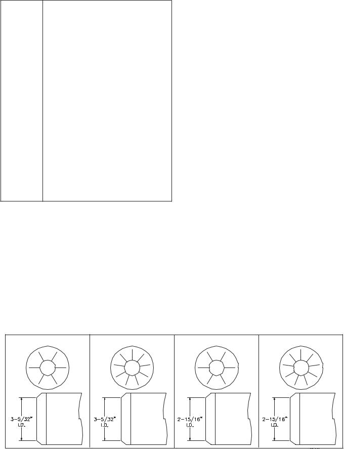
Table 2 – Air Tube Combinations (ATC) & Dimensions
|
|
ATC codes for usable air tube lengths dim. “A” (Figure 3) |
Firing rate range (gph)Min-Max |
|||||||
|
|
3” |
5” |
7” |
9” |
ATC Code |
Head |
AFII 85 |
AFII 100 |
AFII 150 |
Adjustable |
w/stop screwHead Design |
HLX30 |
HLX50 |
HLX70 |
HLX90 |
HB |
AF2-6 |
0.4-0.85 gph |
0.65-1.00 gph |
0.75-1.35 gph |
HLX30 |
HLX50 |
HLX70 |
HLX90 |
HE |
AF2-9 |
N/A |
0.65-1.00 gph |
0.75-1.35 gph |
||
|
|
HLX30 |
HLX50 |
HLX70 |
HLX90 |
HC |
AF2-9 |
N/A |
0.65-1.00 gph |
0.75-1.50 gph |
|
|
HLX30 |
HLX50 |
HLX70 |
HLX90 |
HD |
AF2-6 |
0.40-0.85 gph |
0.65-1.00 gph |
0.75-1.10 gph |
|
|
|
|
|
|
|
|
|
|
|
DesignHead |
|
FBX30 |
FBX50 |
FBX70 |
FBX90 |
HFXS |
FB0 |
0.40-0.65 gph |
0.55-0.75 gph |
0.75-1.00 gph |
Fixed- |
FBX30 |
FBX50 |
FBX70 |
FBX90 |
HGXS |
FB3 |
0.55-0.85 gph |
0.55-1.10 gph |
0.85-1.20 gph |
|
|
|
|||||||||
|
|
FBX30 |
FBX50 |
FBX70 |
FBX90 |
HHXS |
FB4 |
N/A |
0.75-1.10 gph |
1.10-1.25 gph |
|
|
FBX30 |
FBX50 |
FBX70 |
FBX90 |
HIXS |
FB6 |
N/A |
0.85-1.15 gph |
1.15-1.35 gph |
|
|
|
|
|
|
|
|
|
|
|
|
|
HB 6 slot |
|
HC 9 slot |
|
HD 6 slot |
HE 9 slot |
|||
RWB 6104 BAFII R01 |
Page 5 |
 Loading...