


PARTS & ACCESSORIES
Description / Applications
The Beckett AquaSmart™ is an advanced boiler control designed for use on residential and light commercial boiler systems. All models include the option of enabling Beckett HeatManager™ dynamic temperature reset that, when selected, provides up to 20% fuel consumption savings. The control includes a backlit LCD digital display with touch pad to easily program temperature limits, differentials, and other advanced options. The AquaSmart™ also has memory storage of system history for help with diagnostics and troubleshooting.

Table of Contents |
|
Features........................................................................ |
2 |
Technical Specifications............................................. |
3 |
Electrical Ratings .......................................................................... |
3 |
Temperature Ranges and Differentials.......................................... |
3 |
Environmental Ratings .................................................................. |
3 |
Approvals ...................................................................................... |
3 |
Installation.................................................................... |
4 |
Mounting ....................................................................................... |
4 |
AquaSmart Models and Cross-Reference Guide.......................... |
5 |
Removing the Control to be Replaced .......................................... |
7 |
Installing the Temperature Sensor ................................................ |
7 |
Installing the 2-in-1 Sensor ........................................................... |
8 |
2-in-1 Sensor Technical Specifications ......................................... |
8 |
2-in-1 Installation Instructions ....................................................... |
9 |
Test the Low Water Cut-off (LWCO) Safety Function.................... |
9 |
Installing the AquaSmart Control ..................................................... |
10 |
Immersion Well or 2-in-1 Sensor................................................ |
10 |
Appliance Surface ...................................................................... |
10 |
Wiring ........................................................................ |
10 |
Wiring the AquaSmart Control..................................................... |
11 |
Programming Basic Functions ................................ |
25 |
A. Temperature High Limit.......................................................... |
25 |
B. Temperature Low Limit........................................................... |
25 |
C. Temperature High Limit Differential ....................................... |
25 |
D. Temperature Low Limit Differential ........................................ |
26 |
Programming Additional Options ............................ |
26 |
A. Changing the Heat Manager Settings.................................... |
26 |
B. Viewing the Boiler Cycle History............................................ |
26 |
C. Changing the Circulator Settings........................................... |
27 |
D. Changing Domestic Hot Water Priority (DHWP) Setting ....... |
28 |
E. Selecting Fahrenheit or Celsius Temperature Display........... |
28 |
F. Changing Low Water Cut-Off (LWCO) Setting ....................... |
28 |
AquaSmart Operation ............................................... |
30 |
Control Checkout Procedure...................................................... |
30 |
How a Boiler Control Works ....................................................... |
31 |
Display Boiler Status Mode ........................................................ |
32 |
Troubleshooting ........................................................ |
32 |
Lockout....................................................................................... |
32 |
HeatManager Technology ......................................... |
32 |
Final Checklist ........................................................... |
33 |
Accessories ............................................................... |
33 |
Service........................................................................ |
33 |
Mounting Template.................................................... |
35 |
Limited Warranty Information .................................. |
36 |
2
Features
○HeatManager™ dynamic temperature reset for additional energy savings
—DOE 2012 Compliant
—Meets NR CAN proposed 2012 requirements
○Advanced microprocessor-based design
○Backlit LCD digital display with installer programming touch pad
○Quick access to system cycle history
○Onboard power disconnect switch (optional)
○High/Low limit and High/Low differential adjustments
○24Vac Thermostat compatible
○Circulator control - 120Vac
○Zone Control - 120Vac (programmable priority override for domestic hot water)
○Temperature sensor mounts in standard immersion wells
○Compatible retrofit for most standard boiler temperature controls
○Programmable circulator-on and -off delays
○Helps prevent freeze-up by energizing circulator and ZC if an error condition is detected.
○Periodically exercises circulator pump to help prevent sieze-up.
○Cold-start compatible
○6-pin vent damper receptacle on 7500B for easy wiring to most vent dampers.
Electrical Shock, Fire, Explosion and Burn Hazards
This control must be installed, adjusted and put into operation only by a trained, licensed, qualified professional or service agency in accordance with the National Electric Code ANSI/NFPA 70 (Canada CSA C22.1) state, local codes and authorities having jurisdiction.
yThe installer must carefully read and follow the installation and service instructions contained in this manual and make them available to the equipment owner, so they can be kept for future reference.
yThis product is not suitable for temperature control of pools, spas, or Jacuzzis.
yThis product is not to be used as a step or a shelf.

Figure 1 - Getting to know the AquaSmart 7600 Series Control
Electrical Shock Hazard
The AquaSmart control should only be operated with the door attached and securely closed.
Communication Port |
|
TW/TR Terminals |
|
Sensor Mount |
|
|
Touch Pad |
|
Sensor Jack |
Clamping Screw For Sensor |
|
Power Disconnect Switch (Optional) |
|
Rotate door until grooves |
Pull door up |
are aligned |
|
Door Removal |
|
Technical Specifications
Do Not Use This Control in an Application that is Not
Within the Ratings Listed in This Section. Improper Control Operation May Result.
Temperature Ranges and Differentials
○High Limit Setting Range: 100 to 240°F (37 to 115°C)
○High Limit Differential Range: 5 to 45°F (2 to 25°C)
○Low Limit Setting Range: 100 to 220°F (37 to 104°C)
○Low Limit Differential Range: 10 to 45°F (5 to 25°C)
○Factory Range Stops available - consult factory
Electrical Ratings
Input Voltage: 120 Vac - 50/60 Hz.
Input Current: 0.1 A + B1 + C1 + ZC
MAX Input Current: 20A (Reduce to 15A if optional power disconnect switch is used)
24 Vac Thermostat Anticipator Current: 0.1 Amp.
Burner Current Rating (B1):
7600A (oil): 7.4 A at 120 Vac FLA; 44.4 A inrush LRA. 7600B (gas): 1.25 A at 24 Vac; 30 VA (total load).
Circulator Current Rating (C1): 7.4 A at 120 Vac FLA; 44.4 A inrush LRA.
Zone Control Current Rating (ZC): 7.4 A at 120 Vac FLA; 44.4 A inrush LRA.
Environmental Ratings
○Storage Temperature: -40 to +150°F (-40 to +65°C)
○Operating Temperature: -4 to +150°F (-20 to +65°C) 7600B at 50 Hz: -4 to +140°F (-20 to +60°C)
○Maximum Sensing Element Temperature: 250°F (121°C)
○Relative Humidity: 5 to 85% RH, non-condensing and non-crystallizing
Approvals
Underwriters Laboratories Listed to UL353,
UL1998 for U.S. and Canada;
CSA C22.2 No. 24
AquaSmart Boiler Control Manual |
3 |
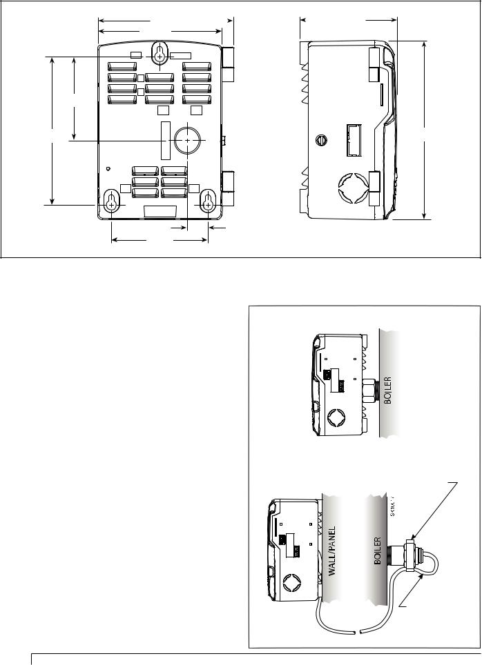
Figure 2 - Basic Dimensions (inches)
|
|
|
|
3.51 |
4.92 |
|
|
|
|
|
|
|||
|
|
|
|
|
4.50
|
3.04 |
5.38 |
6.50 |
|
SK10013 |
.75
3.50
Installation
Mounting
OEM Installation: When replacing an OEM-installed AquaSmart, consult the appliance manufacturer’s wiring diagrams and instructions for additional information.
Retrofit Installation: The AquaSmart can be used to replace most standard boiler temperature controls. For a cross-reference of compatible replacements, refer to
Table 1.
There are two basic methods for mounting the AquaSmart to the boiler as outlined in Figure 3.
1.Sensor/Immersion Well Mounting – This is the most common method. If the existing well is not suitable for any reason, a standard design aftermarket immersion well with the proper dimensions can be purchased from a HVAC distributor. The AquaSmart can then be mounted in the typical way.
2.Surface Mounting – This is sometimes required and is part of the AquaSmart base design. The base has adequate clearance built-in to accommodate the temperature sensor lead exiting the back of the control. A remote mounting kit (Pt. No. 7600RMU) that includes a 48” extension cable and mounting screws can be purchased separately for applications where needed.
Figure 3 - Mounting Options
Sensor/Immersion Well Mounting:
Surface Mounting:
Position the strain relief over the hex, capturing the sensor cable and crimp to secure.
Sensor Lead (a 48” extension cable can be purchased separately)
4

AquaSmart Models and Cross-Reference Guide
Table 1a - Direct Replacements
Honeywell |
Beckett |
Notes |
|
Replacement |
|||
|
|
||
|
|
Must confirm that 7600 VA rating is adequate to meet VA requirements of system. |
|
L7148F (All) |
7600B |
Make sure 7600 B1 output does not exceed 1.25A @ 24VAC (30 VA). |
|
L8148E (All) |
7600 outputs are not rated for 240 VAC. |
||
|
|||
|
|
B2, TW and TR terminals replace TV, T and Z, respectively. |
|
|
|
|
|
L8124A (All) |
7600A |
7600 outputs are not rated for 240 VAC. |
|
L8124C (All) |
|||
|
|
||
L7124A/C (All) |
|
|
|
L7148A (All) |
7600A |
The 7600 has no Honeywell EnviraCOMTM Communications port. |
|
L7224A/C/U (All) |
The diagnostic LED lights are replaced by the 7600’s display. |
||
|
|||
L7248A/C (All) |
|
|
|
|
|
7600 outputs are not rated for 240 VAC. |
|
L8148A (All) |
7600A |
B1 terminal on 7600 utilizes a 1/4” quick connect. |
|
|
|
Set low limit on 7600 to OFF. |
|
L8124E 1016 |
7600B |
7600 outputs are not rated for 240 VAC. |
|
L8148E 1265 |
B2, TW and TR terminals replace TV, T and Z, respectively. |
||
|
|||
L8124M (All) |
7600A |
For replacement with the 7600: Turn low limit off so the circulator is controlled directly by the thermostat and ZC is constantly powered. |
|
L8151A |
7600A |
7600 outputs are not rated for 240 VAC. |
|
Remote mount sensor cable needed (Part No. 52120) |
|||
|
|
||
|
|
|
|
Hydrolevel |
Beckett |
Notes |
|
Replacement |
|||
|
|
||
3100 |
7600B |
Not a suitable replacement if Low Water Cutoff (LWCO) functionality of the 3100 is used. |
|
3150 |
7600A |
Not a suitable replacement if Low Water Cutoff (LWCO) functionality of the 3150 is used. |
|
|
|
|
|
Carlin |
Beckett |
Notes |
|
Replacement |
|||
|
|
||
90524A |
7600A |
Make sure 7600 outputs do not exceed 7.4A. |
|
Available operating limit and differential ranges are not equivalent. Compare the settings to the AquaSmart ranges before replacing. |
|||
|
|
The diagnostic LED lights are replaced by the 7600’s display. |
|
|
|
|
|
White Rodgers |
Beckett |
Notes |
|
Replacement |
|||
|
|
||
11C15-11 |
7600A |
Make sure 7600 outputs do not exceed 7.4A @ 120 VAC. 7600 outputs are not rated for 240 VAC. |
|
8B48A-217 |
7600A |
|
|
11C30-3 |
7600A |
Make sure 7600 outputs do not exceed 7.4A @ 120 VAC. 7600 outputs are not rated for 240 VAC. |
|
11B54-4 |
Available operating limit and differential ranges are not equivalent. Compare the settings to the AquaSmart ranges before replacing. |
||
|
|||
8F48A-351 |
7600B |
|
|
8B43A-601 |
|
||
|
|
||
11C61-12 |
7600A |
Not a suitable replacement if SPDT switch action is required; only break-on-rise available on 7600. |
|
Make sure 7600 outputs do not exceed 7.4A @ 120 VAC. 7600 outputs are not rated for 240 VAC. |
|||
|
|
||
|
|
|
|
|
|
|
Burn, Scald, Explosion, and Equipment Malfunction Hazard
Replacement of the following controls must be done only by a qualified service agency or technician who is trained and experienced in the use of boiler controls.
Carefully follow these guidelines and the directions provided by the manufacturer of the control being replaced.
Note: Beckett assumes no liability for incorrect installation or replacement.
Table 1b - Functional Replacement (Advanced Wiring Needed)
Honeywell |
Beckett |
Notes |
|
||
Replacement |
|
||||
|
|
|
|
||
|
|
|
|
||
L4006A (All) |
7600A or 7600B |
Make sure 7600 outputs do not exceed 7.4A @ 120 VAC. 7600 outputs are not rated for 240 VAC. |
|
||
L4006G 1022 |
7600 will require an additional wire (L2) for operation. Short TW-TR terminals. C1, C2, ZC, and ZR are unused. |
|
|||
(Based on System |
|
||||
L4006H 1004 |
Set low limit on 7600 to OFF. |
|
|||
Voltage |
|
||||
L4008A (All) |
Available operating limit and/or differential ranges may not be equivalent. Compare the settings to the AquaSmart ranges before replacing. |
||||
Requirements) |
|||||
L4080B/D |
To use with a millivolt system, an appropriate voltage relay with isolated gold plated contacts must be added to switch the millivolt circuit. |
|
|||
|
|
||||
|
|
|
|
||
|
7600A or 7600B |
Requires the addition of a manual-reset high limit. |
|
||
L4006E (All) |
Make sure 7600 outputs do not exceed 7.4A @ 120 VAC. 7600 outputs are not rated for 240 VAC. |
|
|||
(Based on System |
7600 will require an additional wire (L2) for operation. Short TW-TR terminals. C1, C2, ZC, and ZR are unused. |
|
|||
L4008E (All) |
|
||||
Voltage |
Set low limit on 7600 to OFF. |
|
|||
L4080F/G |
|
||||
Requirements) |
Available operating limit and/or differential ranges may not be equivalent. Compare the settings to the AquaSmart ranges before replacing. |
||||
|
|||||
|
|
To use with a millivolt system, an appropriate voltage relay with isolated gold plated contacts must be added to switch the millivolt circuit. |
|
||
|
|
|
|
|
|
|
|
|
|
5 |
|
AquaSmart Boiler Control Manual |
|
||||
Table 1b (continued from previous page)
Honeywell |
Beckett |
Notes |
|
Replacement |
|||
|
|
||
|
7600A or 7600B |
|
|
L4081A/B |
(Based on System |
Remove switching relay, if used, from the system when replacing the L4081 or L6081. |
|
L6081A/C |
Voltage |
Make sure 7600 outputs do not exceed 7.4A @ 120 VAC. 7600 outputs are not rated for 240 VAC. |
|
|
Requirements) |
|
|
|
|
|
|
|
|
Not a suitable replacement if SPDT switch action is required; only break-on-rise available on 7600. |
|
L6006A (All) |
7600A or 7600B |
To use with a millivolt system an appropriate voltage relay with isolated gold plated contacts must be added to switch the millivolt circuit. |
|
L6006C 1018 |
(Based on System |
Make sure 7600 outputs do not exceed 7.4A @ 120 VAC. 7600 outputs are not rated for 240 VAC. |
|
L6008A 1192 |
Voltage |
7600 will require an additional wire (L2) for operation. Short TW-TR terminals. C1, C2, ZC, and ZR are unused. |
|
L6008A 1242 |
Requirements) |
Set low limit on 7600 to OFF. |
|
|
|
Available operating limit and/or differential ranges may not be equivalent. Compare the settings to the AquaSmart ranges before replacing. |
|
|
|
|
|
|
7600A or 7600B |
|
|
L8124B 1039 |
(Based on System |
To use with a millivolt system an appropriate voltage relay with isolated gold plated contacts must be added to switch the millivolt circuit. |
|
L8148J 1009 |
Voltage |
7600 outputs are not rated for 240 VAC. |
|
|
Requirements) |
|
|
|
|
|
|
Carlin |
Beckett |
Notes |
|
Replacement |
|||
|
|
7600A or 7600B
90200A (Based on System Voltage
Requirements)
Make sure 7600 outputs do not exceed 7.4A. Set low limit on 7600 to OFF.
Available operating limit and differential ranges are not equivalent. Compare the settings to the AquaSmart ranges before replacing.
90000 (All) |
7600A or 7600B |
Requires the addition of a manual-reset high limit. |
|
90200E |
(Based on System |
Make sure 7600 outputs do not exceed 7.4A. |
|
90200EL |
Voltage |
Set low limit on 7600 to OFF. |
|
90300B |
Requirements) |
Available operating limit and differential ranges are not equivalent. Compare the settings to the AquaSmart ranges before replacing. |
|
|
|
|
|
|
7600A or 7600B |
Not a suitable replacement if SPDT switch action is required; only break-on-rise available on 7600. |
|
90200D |
(Based on System |
Make sure 7600 outputs do not exceed 7.4A. |
|
Voltage |
Set low limit on 7600 to OFF. |
||
|
|||
|
Requirements) |
Available operating limit and differential ranges are not equivalent. Compare the settings to the AquaSmart ranges before replacing. |
|
|
|
|
|
White |
Beckett |
Notes |
|
Rodgers |
Replacement |
||
|
11B06-1 |
|
11D18-1 |
7600A or 7600B |
11B18-101 |
(Based on System |
11B30-104 |
Voltage |
11B02-1 |
Requirements) |
1145-33 |
|
|
|
Make sure 7600 outputs do not exceed 7.4A @ 120 VAC. 7600 outputs are not rated for 240 VAC.
7600 will require an additional wire (L2) for operation. Short TW-TR terminals. C1, C2, ZC, and ZR are unused. Set low limit on 7600 to OFF.
11B06-46 |
7600A or 7600B |
Make sure 7600 outputs do not exceed 7.4A @ 120 VAC. 7600 outputs are not rated for 240 VAC. |
|
(Based on System |
7600 will require an additional wire (L2) for operation. Short TW-TR terminals. C1, C2, ZC, and ZR are unused. |
||
11B95-31 |
|||
Voltage |
Set low limit on 7600 to OFF. |
||
11B18-153 |
|||
Requirements) |
Available operating limit and/or differential ranges are not equivalent. Compare the settings to the AquaSmart ranges before replacing. |
||
|
|||
|
|
|
|
11D82-1 |
7600A or 7600B |
Not a suitable replacement if SPDT switch action is required; only break-on-rise available on 7600. |
|
11D31-1 |
|||
(Based on System |
7600 outputs are not rated for 240 VAC. |
||
1131-102 |
|||
Voltage |
7600 will require an additional wire (L2) for operation. Short TW-TR terminals. C1, C2, ZC, and ZR are unused. |
||
1127-2 |
|||
Requirements) |
Set low limit on 7600 to OFF. |
||
11A79-2 |
|||
|
|
||
|
|
|
|
|
|
Not a suitable replacement if SPDT switch action is required; only break-on-rise available on 7600. |
|
|
7600A or 7600B |
7600 outputs are not rated for 240 VAC. |
|
1127-9 |
(Based on System |
7600 will require an additional wire (L2) for operation. Short TW-TR terminals. C1, C2, ZC, and ZR are unused. |
|
Voltage |
Set low limit on 7600 to OFF. |
||
|
|||
|
Requirements) |
Available operating limit and/or differential ranges may not be equivalent. Compare the settings to the AquaSmart ranges before |
|
|
|
replacing. |
|
|
|
|
7600A or 7600B
11B27-9 (Based on System Voltage
Requirements)
Requires the addition of a manual-reset high limit.
Make sure 7600 outputs do not exceed 7.4A @ 120 VAC. 7600 outputs are not rated for 240 VAC.
7600 will require an additional wire (L2) for operation. Short TW-TR terminals. C1, C2, ZC, and ZR are unused. Set low limit on 7600 to OFF.
Available operating limit and/or differential ranges are not equivalent. Compare the settings to the AquaSmart ranges before replacing.
7600A or 7600B
(Based on System
8J48A-209 To use with a millivolt system an appropriate voltage relay with isolated gold plated contacts must be added to switch the millivolt circuit. Voltage
Requirements)
6
Removing the Control to be Replaced
Electrical shock hazard.
Disconnect all electrical power to the appliance circuit before replacing the control. There may be more than one disconnect switch.
1.Compare the attached wires to available wiring diagrams on the control cover and to the devices to which they can be traced. If wiring diagrams have been lost they are available later in this manual.
2.Label each wire accordingly, to ensure accurate reconnection. (Masking tape works well for labeling.)
3.Remove each wire from the old control. Make sure each label is intact.
4.Loosen the control mounting arrangement and remove the control from the system.
5.Make note of the temperature settings for high limit, low limit and differentials. This will provide important reference data for the new control adjustment. Please note that differentials may be used differently in other manufacturer’s controls. See Figure 19 & 16 toward end of manual for a description of how the AquaSmart’s differentials work. Consult the manual of the control being replaced for information regarding its differentials.
Installing the Temperature Sensor
This is very important for successful control operation.
Burn and Scald Hazard
Excessive water temperatures could cause explosion, burns, scalding, pressure relief flooding and fitting leaks.
yCarefully follow the outlined procedures for temperature sensor installation to ensure accurate water temperature sensing and effective control operation.
yMake sure the plumbing for domestic hot water has anti-scald valve protection.
1.Make sure the immersion well is clean inside, has no leaks, is of proper length and is otherwise suitable for receiving the new control and temperature sensor.
2.Replace questionable wells with new ones and use pipe sealant to seal the threads.
3.Grasp the sensor lead, just behind the sensor probe and carefully insert it into the well until it comes to rest at the very end of the well. The sensor is designed with radial splines to provide a snug fit in most standard wells.
4.The thermal time constant of the sensor is 40 seconds. Consider using thermal grease if faster response in desired.
5.Surface mounting may require additional lead length to reach the control receptacle. Use the extension cable (part no. 52120), found in the 7600RMU Remote Mount Kit, to extend the lead by 48”.
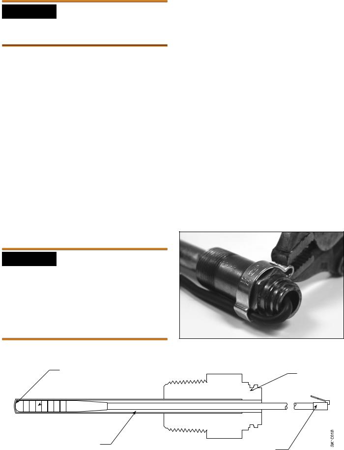
6.Install the strain relief (part no. 3266201) as shown, capturing the cable against the hex. Crimp the strain relief opposite side of the cable. This anchors the sensor securely inside the immersion well.
7.Plug the temperature sensor lead terminal into the receptacle on the control base. See Figure 10.
Note: The sensor is not tested and approved for being mounted to the outside of a pipe. It is for use in immersion wells only.
Figure 4b - Strain Relief
Figure 4a - Installation of Temperature Sensor in Immersion Well
Sensor must butt against end |
Brass Fitting |
|
 Temperature Sensor
Copper Well Tube
Sensor connects to Beckett AquaSmart
AquaSmart Boiler Control Manual |
7 |
Installing the 2-in-1 Sensor
Do not use in steam applications. For use in
hot water boilers or water heaters only. Do not use outside of the intended use and specifications.
Leak, Burn, and Scald Hazards
Incompatible thread sealants could severely damage the sensor threads.
yOnly use Teflon® Tape or Rectorseal® No. 5® (soft-set).
yDO NOT use any anaerobic fast-setting sealants such as, but not limited to, Loctite®, Leak Lock®, Permatex®, or Gasoila®.
yCall RWB Technical Services at 1(800)645-2876 to confirm, if unsure.
For proper operation, there must be a secure electrical bond
between the green sensor wire from the sensor and the boiler metal vessel in direct contact with the boiler water. Failure to secure an electrical bond will result in the AquaSmart locking out and displaying, “LOCKOUT - LOW WATER”.
Explosion,
Burn and Scald Hazards
Excessive water temperatures could cause explosion, burns, scalding, pressure relief flooding and fitting leaks.
yThe 2-in-1 Sensor shall only be installed by a trained professional.
yThe sensor must be installed in the proper location for correct low water cut-off (LWCO) operation in accordance with the Boiler Manufacturer’s instructions.
yThe 2-in-1 sensor body is installed directly into the boiler wall tapped hole in place of an immersion well.
yCarefully follow the outlined procedures for temperature sensor installation to ensure accurate water temperature sensing and effective control operation.
yMake sure the plumbing for domestic hot water has anti-scald valve protection.
yFollow all applicable safety codes, rules and guidelines for installing an immersion well. Improper installation can result in the Boiler overheating.
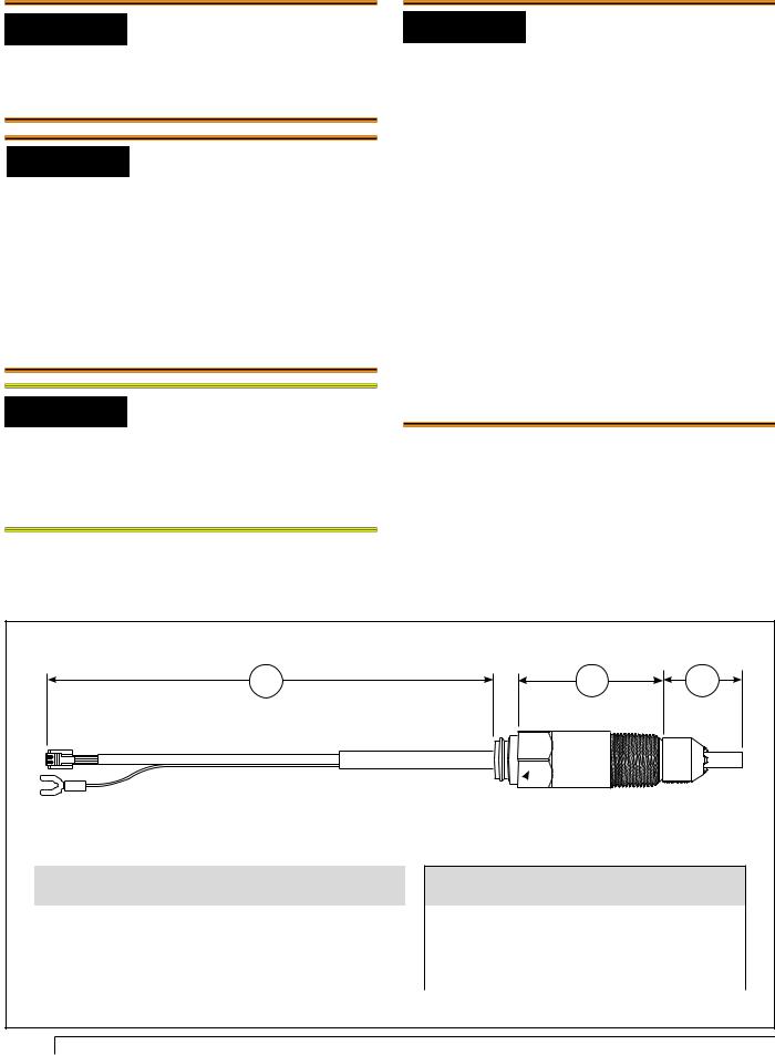
Figure 5 - Overall Dimensions & Specifications
A |
B |
C |
1-1/8” hex 
Part No. |
A |
B |
C |
|
Lead Length |
Insulation Depth |
Insertion Depth |
||
|
||||
|
|
|
|
|
76002N1S01 |
8-1/4” |
1-1/2” |
1-5/8” |
|
76002N1S02 |
6-1/4” |
3-1/2” |
1-5/8” |
|
76002N1S05 |
5” |
4-3/4” |
1-5/8” |
|
76002N1S06 |
8-1/4” |
1-1/2” |
7/8” |
|
|
|
|
|
Specifications
Storage Temperature Range |
-40° to 250°F |
Operating Temperature Range |
-32° to 250°F |
Maximum Pressure |
250 PSIG |
Installation Torque Range (Screw-in) |
185 - 200 in/lbs. |
|
|
8
2-in-1 Installation Instructions
This is very important for successful control operation.
1.Remove the existing immersion well. Clean the threads in the boiler port tapping. Follow all applicable safety codes, rules and guidelines for removing/ installing immersion wells.
2.Apply pipe sealant to the 2-in-1 sensor threads and install it securely into the port. BECKETT RECOMMENDS ONLY TO USE TEFLON TAPE OR RECTORSEAL NO. 5 PIPE SEALANT.
3.Tighten with 1-1/8” open end or box wrench. Pipe wrenches, pliers, and adjustable wrenches will damage/round-off the hex.
4.Securely install the AquaSmart control to the sensor. Plug the 2-in-1 Sensor RJ connector (phone jack style) into the receptacle (Item a, Figure 6) on the control.
5.Route the 36” green wire through the AquaSmart bottom rectangular slot (Item c, Figure 6). Securely install the fork connector of the 36” ground wire and the ground wire from the 2-in-1 sensor under the ground screw at the bottom of the control (Item b,
Figure 6).
6.Thoroughly clean the pipe surface and securely tighten the pipe clamp on the water inlet pipe to the boiler as close to the boiler as possible.
7.Route the 36” green ground wire to the pipe clamp then cut to proper length, if necessary.
8.Strip the wire and insert the stripped end into hole on the pipe clamp (item d, Figure 7). Tighten retaining screw against the wire making sure that you have good contact.
9.Complete control wiring and fill the appliance with water to the pressure required, according to appliance manufacturer’s instructions. Make sure all air is purged from the system and there are no leaks. Turn on power to the appliance and observe one call for heat cycle with shut off at set temperature.
Test the Low Water Cut-off (LWCO) Safety Function
WARNING! Avoid touching or shorting the live terminals during this test.
Turn electric power ON to energize AquaSmart control. Perform the following tests to verify the LWCO function.
•For AquaSmart 7600A: Remove the green sensor lead from the ground screw. The sensor should cause the AquaSmart display to indicate, “LOCKOUT – LOW WATER”. If it does not, replace the sensor.
•For AquaSmart 7600B: Remove the green sensor lead from the ground screw and remove both the B1 and B2 (24 Vac) leads from their terminals. The sensor should cause the AquaSmart display to indicate, “LOCKOUT – LOW WATER”. If it does not, replace the sensor.
•Attach wires and tighten terminal screws securely when testing is complete.
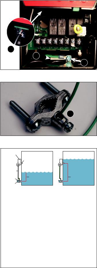
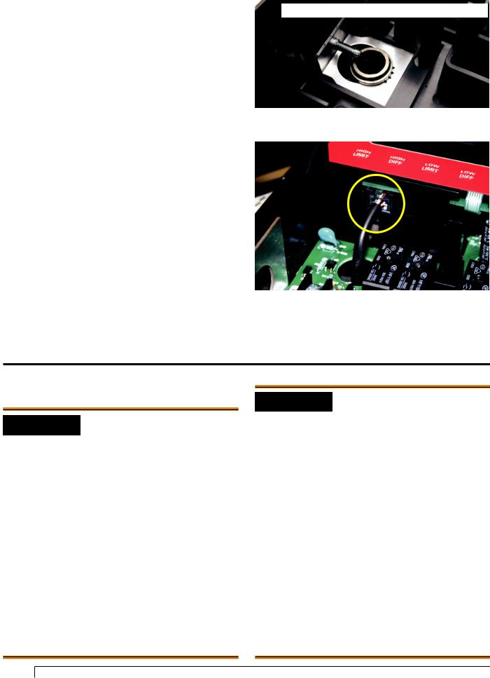
Figure 6 - Sensor lead & ground screw connections
a
c
b
Figure 7 - Ground Clamp and Grounding Wire
d
Figure 8 - Sensor Water Detection Method
AquaSmart
Boiler Control
|
2-IN-1 SENSOR |
|
|
Ground Screw |
Water Not Present |
|
|
|
Water Present |
||
Ground Wire |
|
|
|
Pipe Clamp |
Incomplete |
Complete |
|
Circuit |
Circuit |
||
|
|||
Water Inlet |
|
|
The AquaSmart 2-in-1 Sensor uses the “conduction” method to detect whether water is present in the boiler. This is done by using the water in the boiler itself to “conduct” a signal and complete an electrical circuit. It is necessary that the ground wire from the sensor be bonded to the boiler wall (not the jacket - unless the jacket is bonded to the boiler wall). When water is not present, there is no “conduction” and the circuit is incomplete.
For the AquaSmart we recommend that a grounding pipe clamp be mounted to the water inlet pipe, and that a ground wire be bonded from the pipe clamp to the green terminal inside the AquaSmart control. The 2-in-1 sensor green “ground wire” shall also be bonded to the green terminal in the AquaSmart control.
AquaSmart Boiler Control Manual |
9 |
Installing the AquaSmart Control
(Refer back to Figure 3 for appropriate mounting method).
Immersion Well or 2-in-1 Sensor
1.Mount the control by aligning the 7/8” diameter hole (found on back) around the mating feature of the immersion well or 2-in-1 sensor and press into place. Position the control upright and tighten down the #10 screw located on the left side of the control. Tighten so that control is securely in place (Figure 9).
2.Plug the temperature sensor lead terminal into the receptacle on the control base. See Figure 10.
Appliance Surface
1.Use the AquaSmart mounting template to locate the mounting holes in a desired location on mounting surface. The template can be found in the back of this manual.
2.Use (3) #8 x 3/4” self drilling screws (.110 hole diameter if pre-drilling) included in the installation kit. Run screws into mounting surface, leaving a 1/4” space between bottom of screw head and mounting surface.
3.Open the cover of the AquaSmart control to expose key hole locations in plastic case. Align key holes over mounting screws and secure in place.
4.Plug the temperature sensor lead terminal into the receptacle on the control base. See Figure 10.
5.If necessary, use the 48” cable extension to connect sensor to control base. Refer back to Figure 3.
Figure 9 - Mounting Clamp and Screw for Immersion Well
For clarity, the printed circuit board is not shown.
Figure 10 - Temperature Sensor Lead/Receptacle
Wiring
Electrical Shock, Fire,
Explosion and Burn Hazards
This control must be installed, adjusted and put into operation only by a trained, licensed, qualified professional or service agency in accordance with
the latest revision of the National Electric Code ANSI/ NFPA 70 (Canada CSA C22.1) state, local codes and authorities having jurisdiction.
yFollow the appliance manufacturer’s wiring diagrams and note all safety controls.
yTypical safety controls include high temperature or pressure limits, low water cutoffs, anti-scald valves, pressure relief valves and water feed valves.
yVerify all limits and safety controls are installed and functioning correctly, as specified by the appliance manufacturer, applicable safety standards, codes and all authorities having jurisdiction.
yProvide ground wiring to the appliance, burner and controls.
10
Electrical Shock Hazard.
Can Cause Severe Injury, Death, or Equipment Damage.
Disconnect power before wiring to prevent electrical shock or equipment damage.
yAll wiring must comply with local electrical codes and ordinances. The limits given in the specifications section must not be exceeded when applying this control. Terminals on the AquaSmart are approved for copper wire only.
yRefer to the label on the inside of the AquaSmart door or to Technical Specifications in this manual for Electrical ratings and maximum load information. Use manufacturer instructions when wiring controlled equipment or refer to typical hookups in Figure 12 through Figure 17.
yMore than one service switch may be needed to disconnect all power to the AquaSmart. The optional power disconnect switch interrupts power to the AquaSmart control. Depending on system wiring, some terminals and connections (most notably ZR and the input to the optional power disconnect switch) may still be live.
Explosion Hazard. Can Cause Severe Injury, Death
or Property Damage.
Use this product only in systems with a pressure relief valve.
Wiring the AquaSmart Control
○Consult the appliance wiring diagrams to check the manufacturer’s specifications.
○Refer to Figure 12 through Figure 17 for some typical wiring diagrams.
○Verify the wires are still labeled correctly and make connections to the appropriate terminals on the control wiring terminal strip.
○Provide disconnect means and overload protection as required on power supply.
○Connect control conduit bracket to earth ground using the supplied grounding screw.
○B1 terminal is a 1/4 in. tab terminal (quick connect).
Some Thermostats Are Polarity Sensitive
Reversed polarity could cause erratic cycling of the boiler control.
yConnect the red thermostat wire (from the RH or R
terminal of the thermostat) to the TR terminal on the control.
yConnect the white thermostat wire (from the W terminal of the thermostat) to the TW terminal on the control.
Figure 11 - TR, B2, & Vent Damper Connections
TR
6-Position Vent
Damper Receptacle
B2
Observe proper polarity when wiring L1 and L2. If polarity is reversed, a
call for heat on the ZR input may not be recognized.
7600B only: TERMINALS TR (Z or hot) and B2 (TV or ground) offer a
24-volt supply for operating other 24 VAC equipment on the boiler. IMPORTANT: TO PREVENT DAMAGE TO
THE CONTROL, DO NOT OVERLOAD THE TRANSFORMER. The AquaSmart is equipped with a 30VA transformer. Make sure that the total load, including the burner circuit and TR & B2 connections do not exceed 30VA. See Figure 11.
How to calculate VA - Add all AMP ratings of 24VAC components in this circuit and multiply sum by 24 volts.
(Example: .4 + .4 + .2 + .2 = 1.2A x 24V = 28.8 VA)
When powering multiple circulators from the C1 and C2 terminals, take extra care not to exceed the output’s reading. If the sum
of the full load amps of all the circulators exceeds the output’s rating, use the C1 and C2 terminals to power the coil of a multiple-pole contactor; the contacts of which can be wired to switch L1 to each circulator.
To wire a vent damper to the 7600B, first remove jumper plug from 6-
position receptacle and then connect 6-pin connector of the vent damper to the receptacle. See Figure 11. Once the 7600B is operated with a vent damper, it will not function without one (even if the jumper plug is replaced).
Water Flow Symbols Key (Figures 12 through 17)
-Air Vent
-Air Separator
-Expansion Tank
-Isolation Valve
-Pressure Regulator
Z- Zone Valve
-Check Valve
-Circulator
AquaSmart Boiler Control Manual |
11 |
 Loading...