


Beckett AF/AFG Oil Burner Manual
Type ‘M’ Air Tube Combination
(AFG Models only)
Type ‘L1’ Head |
Type ‘V1’ Head |
! WARNING Potential for Fire, Smoke and Asphyxiation Hazards
Incorrect installation, adjustment, or misuse of this burner could result in death, severe personal injury, or substantial property damage.
To the Homeowner or Equipment Owner:
yPlease read and carefully follow all instructions provided in this manual regarding your responsibilities in caring for your heating equipment.
yContact a professional, qualified service agency for installation, start-up or service work.
ySave this manual for future reference.
To the Professional, Qualified Installer or Service Agency:
yPlease read and carefully follow all instructions provided in this manual before installing, starting, or servicing this burner or heating system.
yThe Installation must be made in accordance with all state and local codes having jurisdiction.
RWB 6104 BAFG R02 |
Page 1 |

Table of Contents |
|
Hazard Definitions and Owner’s Information ........................................................................................ |
3 |
Information To Be Used Only By Qualified Service Technicians |
|
General Information ......................................................................................................................................... |
3 |
Table 1 Burner Specification................................................................................................................................ |
4 |
Table 2 Air Tube Combination (ATC) Codes ………………………………………………………….. .....................4 |
|
Notice Special Requirements .............................................................................................................................. |
5 |
Inspect/Prepare Installation Site................................................................................................................. |
5 |
Chimney or Vent ................................................................................................................................................. |
5 |
Combustion Air Supply ........................................................................................................................................ |
5 |
Clearances to burner and appliance ................................................................................................................... |
6 |
Combustion chamber - Burner Retrofitting.......................................................................................................... |
6 |
Prepare the Burner........................................................................................................................................... |
6 |
Low Firing Rate Baffle ......................................................................................................................................... |
6 |
Burner Fuel Unit .................................................................................................................................................. |
6 |
Nozzle and Pump Pressure................................................................................................................................. |
6 |
Attach Air Tube .................................................................................................................................................... |
7 |
Install Burner Nozzle ........................................................................................................................................... |
7 |
Check/Adjust Electrodes ..................................................................................................................................... |
7 |
Check/Adjust ‘Z’ Dimension - F Heads................................................................................................................ |
8 |
Check/Adjust ‘Z’ Dimension - L & V Heads ......................................................................................................... |
9 |
Servicing nozzle line assembly ......................................................................................................................... |
10 |
Mount burner on appliance......................................................................................................................... |
10 |
Mounting Options .............................................................................................................................................. |
10 |
Mounting Dimensions........................................................................................................................................ |
10 |
Connect Fuel Lines ........................................................................................................................................... |
10 |
Wire Burner ....................................................................................................................................................... |
11 |
Burner Packaged with Appliance....................................................................................................................... |
11 |
Burner Installed at Job Site ............................................................................................................................... |
11 |
Special Wiring Required with Covered Burners ................................................................................................ |
11 |
Start-up Burner/Set Combustion.............................................................................................................. |
13 |
Set Combustion with Test Instruments .............................................................................................................. |
13 |
Perform Regular Maintenance................................................................................................................... |
14 |
Parts Diagram................................................................................................................................................... |
15 |
Beckett Limited Warranty Information ................................................................................................... |
16 |
NOTICE
This manual contains information that applies to both AF and AFG burners. These burners may appear to be basically identical, but there are differences in design and performance. Please review the comparison chart below:
Feature |
AF |
AFG |
Static Pressure Capability |
Conventional - Low range |
Enhanced - Medium range |
Blower Wheel Design |
Standard strip |
Special tablock |
Inlet Airflow Design |
Standard inlet bell |
Special airguide |
UL Air Tube Combinations |
“F” Series ONLY |
“F” or “M” Series |
Igniter Gaskets Baseplate/Barrier |
Optional, as specified |
Required, always specified |
Low Firing Rate Baffle |
Not required |
Required, per specification |
Page 2 |
RWB 6104 BAFG R02 |
Hazard Definitions
! DANGER Indicates an imminently haz- ardous situation, which, if not
avoided, will result in death, serious injury, or property damage.
WARNING Indicates a potentially
! hazardous situation, which, if not avoided, could result in death, severe personal injury, and/or substantial property damage.
CAUTION Indicates a potentially haz- ! ardous situation, which, if
not avoided, may result in personal injury or property damage.
Within the boundaries of the hazard warning, there will be information presented describing consequences if the warning is not heeded and instructions on how to avoid the hazard.
NOTICE
Intended to bring special attention to information, but not related to personal injury or property damage.
! WARNING Owner’s Responsibility
Incorrect installation, adjustment, and use of this burner could result in severe personal injury, death, or substantial property damage from fire,
carbon monoxide poisoning, soot or explosion.
Contact a professional, qualified service agency for the installation, adjustment and service of your oil heating system. This work requires technical training, trade experience, licensing or certification in some states and the proper use of special combustion test instruments.
Please carefully read and comply with the following instructions:
yNever store or use gasoline or other flammable liquids or vapors near this burner or appliance.
yNever attempt to burn garbage or refuse in this appliance.
yNever attempt to light the burner/appliance by throwing burning material into the appliance.
yNever attempt to burn any fuel not specified and approved for use in this burner.
yNever restrict the air inlet openings to the burner or the combustion air ventilation openings in the room.
General Information
To the Owner:
Thank you for purchasing a Beckett burner for use with your heating appliance. Please pay attention to the Safety Warnings contained within this instruction manual. Keep this manual for your records and provide it to your qualified service agency for use in professionally setting up and maintaining your oil burner.
Your Beckett burner will provide years of efficient operation if it is professionally installed and maintained by a qualified service technician. If at any time the burner does not appear to be operating properly, im- mediately contact your qualified service agency
for consultation.
We recommend annual inspection/service of your oil heating system by a qualified service agency.
Daily – Check the room in which your burner/appliance is installed. Make sure:
•Air ventilation openings are clean and unobstructed
•Nothing is blocking burner inlet air openings
•No combustible materials are stored near the heating appliance
•There are no signs of oil or water leaking around the burner or appliance
Weekly
• Check your oil tank level. Always keep your oil tank full, especially during the summer, in order to prevent condensation of moisture on the inside surface of the tank.
! WARNING Do NOT Alter the Original Burner Design
Tampering with or altering the burner design could seriously impair performance, resulting in loss of static pressure, damage to the system components, reduced air volume, heavy smoke, flame impingement, appliance sooting, hot gas puff-back, and asphyxiation or fire hazards.
Maintain the design to its original configuration. Only use parts specified for AF or AFG Burners
Do NOT remove the air guide from the AFG chassis.
Do NOT use ‘M’ Series air tube combinations on AF Burners.
Never try to convert and AF to and AFG or vice versa Any design alteration will:
yVoid UL Listing
yVoid manufacturer’s warranties
ySeriously impact burner performance
yGreatly increase your liability risk
RWB 6104 BAFG R02 |
Page 3 |

General Specifications
Table 1 – Burner Specifications
Capacity |
‘F’ Head (AF & AFG) |
||
(Note 1) |
Firing rate range: |
..............0.40 – 3.00 GPH |
|
|
Input: ....................... |
|
56,000 – 420,000 Btu |
|
|
||
|
‘L1’ Head (AFG Only) |
||
|
Firing rate range: .................. |
0.40 - 1.10 GPH |
|
|
Input: ..................... |
|
56,000 – 154,000 Btu/h |
|
‘L2’ Head (AFG Only) |
||
|
Firing rate range: ................. |
0.50 - 1.00 GPH |
|
|
Input: ...................... |
|
70,000 – 140,000 Btu/h |
|
‘V1’ Head (AFG Only) |
||
|
Firing rate range: ................. |
0.75 - 2.75 GPH |
|
|
Input: .................... |
|
105,000 – 385,000 Btu/h |
Certifications/ |
UL certified to comply with ANSI/UL296 & |
||
Approvals |
tested to CSA B140.0 |
||
Fuels |
U. S: No.1 or No.2 heating oil only |
||
|
(ASTM D396) |
||
|
Canada: No. 1 stove oil or No. 2 furnace oil |
||
|
|
only |
|
Electrical |
Power supply: ............... |
120 volts AC, 60 Hz, |
|
|
|
|
single phase |
|
Operating load: ....................... |
5.8 Amps max |
|
|
Motor: ............ |
1/7 hp, 3450 rpm, NEMA 48M |
|
|
|
frame PSC rotation CCW |
|
|
|
when facing shaft end |
|
|
Ignition: ... |
Continuous duty solid-state igniter |
|
Fuel pump |
Outlet pressure: .................................. |
Note 2 |
|
|
|
|
|
Air tube |
ATC code: |
................................... |
See Table 2 |
|
|
|
|
Dimensions |
Height (maximum) ....................... |
12.5 inches |
|
(with cover) |
Width (maximum) .......................... |
15 inches |
|
|
Depth ......................................... |
|
9.25 inches |
|
Air tube diameter ....................... |
4.00 inches |
|
Note 1: Approval agency listed rating for these burners is 0.40 to 3.00 gph. However, the firing rate range is limited by the specific air tube combination being used. Refer to Table 2.
Note 2. See appliance manufacturer’s burner specifications for recommended pump discharge pressure.
|
Professional Service |
|
! WARNING |
||
Required |
Incorrect installation, adjustment, and use of this burner could result in severe personal injury, death, or substantial property damage from
fire, carbon monoxide poisoning, soot or explosion.
Please read and understand the manual supplied with this equipment. This equipment must be installed, adjusted and put into operation only by a qualified individual or service agency that is:
yLicensed or certified to install and provide technical service to oil heating systems.
yExperienced with all applicable codes, standards and ordinances.
yResponsible for the correct installation and commission of this equipment.
ySkilled in the adjustment of oil burners using combustion test instruments.
The installation must strictly comply with all applicable codes, authorities having jurisdiction and the latest revision of the National Fire Protection Association Standard for the installation of Oil-burning Equipment, NFPA 31 (or CSA B139 and B140 in Canada).
Regulation by these authorities take precedence over the general instructions provided in this installation manual.
Table 2 – Air Tube Combination (ATC) codes
Firing |
Head |
Static |
Ven- |
|
|
|
ATC Codes for usable air tube lengths |
|
|
|
|||
Rate |
|
plate |
turi |
|
|
|
|
(‘A’ in inches; See Figure 3.) |
|
|
|
||
(gph) |
|
size |
|
|
|
|
|
|
|
|
|
|
|
(min- |
|
(inch- |
|
4-1/2 |
5 |
5-3/8 |
6-5/8 |
7 |
7-1/4 |
9 |
10-1/2 |
13 |
16 |
max) |
|
es) |
|
|
|
|
|
|
|
|
|
|
|
0.50-0.75 |
F0 |
3-3/8U |
None |
AF44XR |
- |
AF53XR |
AF65XR |
- |
AF72XR |
AF90XR |
AF104XR |
AF130XR |
A160XR |
|
|
|
|
|
|
|
|
|
|
|
|
|
|
0.75-1.25 |
F3 |
2-3/4U |
None |
AF44XN |
- |
AF53XN |
AF65XN |
- |
AF72XN |
AF90XN |
AF104XN |
AF130XN |
AF160XN |
0.85-1.35 |
F4 |
2-3/4U |
None |
AF44WH |
- |
AF53WH |
AF65WH |
- |
AF72WH |
AF90WH |
AF104WH |
AF130WH |
AF160WH |
|
|
|
|
|
|
|
|
|
|
|
|
|
|
0.85-1.65 |
F6 |
2-3/4U |
None |
AF44YB |
- |
AF53YB |
AF65YB |
- |
AF72YB |
AF90YB |
AF104YB |
AF130YB |
AF160YB |
1.10-2.00 |
F12 |
2-3/4U |
None |
AF44XO |
- |
AF53XO |
AF65XO |
- |
AF72XO |
AF90XO |
AF104XO |
AF130XO |
AF160XO |
|
|
|
|
|
|
|
|
|
|
|
|
|
|
1.65-2.50 |
F22 |
2-3/4U |
None |
AF44XP |
- |
AF53XP |
AF56XP |
- |
AF72XP |
AF90XP |
AF104XP |
AF130XP |
AF160XP |
|
|
|
|
|
|
|
|
|
|
|
|
|
|
2.50-3.00 |
F31 |
None |
None |
AF44XS |
- |
AF53XS |
AF65XS |
- |
AF72XS |
AF90XS |
AF104XS |
AF130XS |
AF160XS |
0.50-1.10 |
L1 |
3-3/8U |
8hole |
- |
AFG50MB |
- |
- |
AFG70MB |
- |
AFG90MB |
- |
- |
- |
|
|
|
|
|
|
|
|
|
|
|
|
|
|
0.50-1.00 |
L2 |
2-3/4U |
8hole |
|
AFG50MP |
- |
- |
AFG70MP |
- |
AFG90MP |
- |
- |
- |
0.75-2.75 |
V1 |
2-3/4U |
8hole |
- |
AFG50MD |
- |
- |
AFG70MD |
- |
AFG90MD |
- |
- |
- |
|
|
|
|
|
|
|
|
|
|
|
|
|
|
0.40-0.75 |
F0 |
3-1/2U |
None |
AF44WG |
- |
AF53WG |
AF65WG |
- |
AF72WG |
AF90WG |
AF104WG |
AF130WG |
A160WG |
Page 4 |
RWB 6104 BAFG R02 |
Notice Special Requirements
yFor recommended installation practice in Canada, refer to the latest version of CSA Standard B139 & B140.
yConcealed damage — If you discover damage to the burner or controls during unpacking, notify the carrier at once and file the appropriate claim.
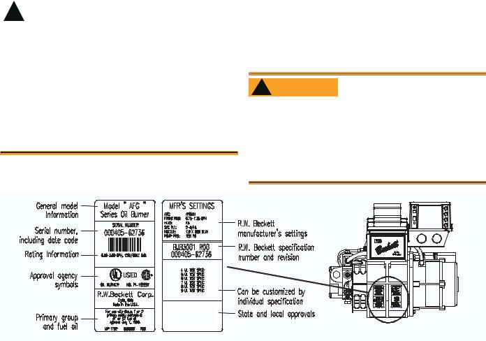
yWhen contacting Beckett for service information
— Please record the burner serial number (and have available when calling or writing). You will find the serial number on the silver label located on the left rear of the burner. Refer to Figure 1.
Inspect/Prepare Installation Site
Chimney or vent
yInspect the chimney or vent, making sure it is properly sized and in good condition for use.
yFor those installations not requiring a chimney, such as through-the-wall vented appliances, follow the instructions given by the appliance and power venter (if used) manufacturers.
|
|
Adequate Combustion |
|
! WARNING |
|
|
and Ventilation Air Supply |
|
|
|
Required |
Failure to provide adequate air supply could seriously affect the burner performance and result in damage to the equipment, asphyxiation, explosion or fire hazards.
yThe burner cannot properly burn the fuel if it is not supplied with a reliable combustion air source.
yFollow the guidelines in the latest editions of the NFPA 31 and CSA-B139 regarding providing adequate air for combustion and ventilation.
Figure 1. Burner label location
Combustion air supply
See NFPA 31 Standard for complete details.
Appliance located in confined space
The confined space should have two (2) permanent openings: one near the top of the enclosure and one near the bottom of the enclosure. Each opening shall have a free area of not less than (1) one square inch per 1,000 BTU’s per hour of the total input rating of all appliances within the enclosure. The openings shall have free access to the building interior, which should have adequate infiltration from the outside.
Exhaust fans and other air-using devices
Size air openings large enough to allow for all airusing devices in addition to the minimum area required for combustion air. If there is any possibility of the equipment room developing negative pressure (because of exhaust fans or clothes dryers, for example), either pipe combustion air directly to the burner or provide a sealed enclosure for the burner and supply it with its own combustion air supply.
Direct air supply and sidewall venting
y Some AFG burners are equipped with combustion air boots to allow use of outside air for combustion.
y When sidewall venting appliances, carefully follow appliance and power venter instructions for installation and wiring.
! WARNING Follow the Outside Air Kit Instructions Exactly
Failure to comply could result in impaired combustion, appliance soot-up, puffback of smoke, and fire or asphyxiation hazards.
yDo not attempt to install outside air piping to the burner without using the outside air kit and instructions.
SK9475
RWB 6104 BAFG R02 |
Page 5 |
 Loading...