


MODEL AFII Oil
Burner
Instruction Manual
AFII 85, AFII 100, AFII 150
Types “HLX” & “FBX” air tube combinations
Voltage: 120 Vac / 60 Hz
AFII burner with type “HLX” air tube
Type “FBX” air tube combinations
AFII
Beckett

Instruction Manual – Model AFII Oil Burner |
Beckett |
|
Contents
Prepare before installing
Verify specifications ……………………………….…………………..…….………….. 3 Be aware of hazard definitions …………….…………….…..………..………………..3 Check certifications/approvals ……………………………………..…………………...3
Notice special requirements ………………….…………...…………..……………….. 3
Prepare burner & site
Inspect/prepare installation site ……………………...…………..………………….… 4 Prepare burner ……………………………...…..…………………..……………………5
HLX arrangement……………….…………….………………………..………………... 6
FBX arrangement …………………………………….….…………..………………….. 7
Adjust, pipe, & wire burner
Mount burner on appliance ………………………………..…………..……………….. 8 Connect fuel lines ………………………………………………………..……………… 8 Wire burner ………………………………………………………………..……………...8, 9
Startup & adjust burner
Startup burner/set combustion ………..……………..….…………..………………….10 Set combustion with instruments …………..………….…………..…………………...10
Service & maintain burner
Perform regular maintenance …………………..……….……………..……….………10 To replace the blower wheel ………………………..……………….………………….10
Replacement parts ……………………………………………………………………….11
Owner’s information and warranty ………………………………….………….……… 12
Table 1 – Air Tube Combination (ATC) codes
AFII AIR TUBE COMBINATION AND FIRING RATE CHART
|
USABLE AIR TUBE LENGTH DIM. “A” (see Fig. 5) |
|
|
|
FIRING RATE RANGE |
|||||||
3” |
|
5” |
7” |
9” |
ATC Code |
|
Head |
|
AFII 85 |
|
AFII 100 |
AFII 150 |
|
|
|
|
|
|
|
|
|
|
|
|
|
|
|
Head Design – Adjustable w/ stop screw |
– typical applications: Wet base boilers |
|
||||||||
HLX30 |
|
HLX50 |
HLX70 |
HLX90 |
HB |
|
AF2-6 |
0.40-0.85 gph |
|
0.65-1.00 gph |
0.75-1.35 gph |
|
|
|
|
|
|
|
|
|
|
|
|
|
|
HLX30 |
|
HLX50 |
HLX70 |
HLX90 |
HC |
|
AF2-9 |
|
N/A |
|
0.65-1.00 gph |
0.75-1.50 gph |
HLX30 |
|
HLX50 |
HLX70 |
HLX90 |
HD |
|
AF2-6 |
0.40-0.85 gph |
|
0.65-1.00 gph |
0.75-1.10 gph |
|
|
|
|
|
|
|
|
|
|
|
|
|
|
HLX30 |
|
HLX50 |
HLX70 |
HLX90 |
HE |
|
AF2-9 |
|
N/A |
|
0.65-1.00 gph |
0.75-1.35 gph |
|
|
Head Design – Fixed – typical applications: Furnaces, Dry base boilers, Water heaters |
|
|||||||||
FBX30 |
|
FBX50 |
FBX70 |
FBX90 |
HFXS |
|
FB0 |
0.40-0.65 gph |
|
0.55-0.75 gph |
0.75-1.00 gph |
|
|
|
|
|
|
|
|
|
|
|
|
|
|
FBX30 |
|
FBX50 |
FBX70 |
FBX90 |
HGXS |
|
FB3 |
|
0.55-0.85 gph |
|
0.55-1.10 gph |
0.85-1.20 gph |
FBX30 |
|
FBX50 |
FBX70 |
FBX90 |
HHXS |
|
FB4 |
N/A |
|
0.75-1.10 gph |
1.10-1.25 gph |
|
|
|
|
|
|
|
|
|
|
|
|
|
|
FBX30 |
|
FBX50 |
FBX70 |
FBX90 |
HIXS |
|
FB6 |
|
N/A |
|
0.85-1.15 gph |
1.15-1.35 gph |
|
|
|
|
|
|
|
|
|
|
|
|
|
2

Beckett
Instruction Manual – Model AFII Oil Burner
Prepare before installing
Verify specifications
Capacity |
“HLX” heads |
|
Firing rate ..……..……………....…... 0.40 – 1.50 GPH |
|
Input ..………..….…………… 56,000 – 210,000 Btu/h |
|
|
|
“FBX” heads |
|
Firing rate ..…..……………………… 0.40 - 1.35 GPH |
|
Input ..………….…..………….56,000 – 189,000 Btu/h |
Fuels |
U. S. …. No. 1 or No. 2 heating oil only (ASTM D396) |
|
Canada ….... No. 1 stove oil or No. 2 furnace oil only |
Electrical |
Power supply ....…….... 120 VAC/60 Hz/single phase |
|
Operating load ……….… 5.8 Amps maximum; Note 1 |
|
Motor …..……… ……………………..1/7 hp, 3450 rpm |
|
……….……...…… rotation CW when facing shaft end |
|
Ignition .……... Continuous duty iron-core transformer |
|
OR ………..... Continuous duty solid state igniter |
Fuel unit |
Outlet pressure ………..…..……………………. Note 2 |
Air tube |
ATC code ……………………….. See Table 1, page 2 |
Dimensions |
Height (maximum) ……….…….….…………13 inches |
|
Width (maximum) ………….………..….. …..14 inches |
|
Depth (chassis only) ………….……….6-11/16 inches |
|
Air tube diameter ………………………….3 ½ inches |
|
|
Note 1. A burner with an electronic igniter will have a lower operating current. The actual load should be determined by a current meter.
Note 2. See appliance manufacturer’s burner specifications for recommended outlet pressure. Pressure is 140 psig unless otherwise noted.
Be aware of hazard definitions
DANGER |
Denotes presence of a hazard which, if ignored, will result in |
severe personal injury, death, or substantial property damage. |
|
|
Denotes presence of a hazard which, if ignored, could result in |
WARNING |
|
severe personal injury, death, or substantial property damage.
CAUTION Denotes presence of a hazard which, if ignored, could result in minor personal injury or property damage.
NOTICE |
Intended to bring special attention to information, but not |
related to personal injury or property damage.
Check certifications/approvals
•Underwriters Laboratories has certified this burner to comply with ANSI/UL 296 and has listed it for use with #1 or #2 fuel oil as specified in ASTM D396. Low sulfur #1 and #2 fuel oils reduce heat exchanger deposits with all burners compared to the standard fuels. Reduced deposits extend the service interval for cleaning and improve the efficiency of the appliance over time. Low sulfur fuels reduce particulate and oxides of nitrogen emissions as well. The Oilheat Manufacturers' Association recommends these fuels as the preferred fuels for this burner.
•State and local approvals are shown on burner rating label (see below).
•All oil burners should be installed in accordance with regulations of the latest revision of the National Fire Protection Association Standard NFPA 31 and in complete accordance with all local codes and authorities having jurisdiction. Regulation of these authorities take precedence over the general instructions provided in this installation manual.
•For recommended installation practice in Canada, refer to the latest version of CSA Standard B139.
Notice special requirements
DANGER This equipment must be installed, adjusted and started only
by a qualified service agency – an individual or agency, licensed and experienced with all codes and ordinances, who is responsible for the installation and adjustment of the equipment. The installation must comply with all local codes and ordinances and with the latest revision of the National Fire Protection Standard for Oil-Burning Equipment, NFPA 31 (or CSA B139).
WARNING |
Read all instructions before proceeding. Follow all |
instructions completely. Failure to follow these instructions could result in equipment malfunction, causing severe personal injury, death or substantial property damage.
NOTICE Concealed damage — If you discover damage to the burner or controls during unpacking, notify the carrier at once and file the appropriate claim.
NOTICE When contacting Beckett for service information — Please record the burner serial number (and have available when calling or writing). You will find the serial number on the silver label located on the top right of the burner, to the left of the air dial. See illustration below.
SK9642 |
3 |
Instruction Manual – Model AFII Oil Burner
Prepare burner & site
Inspect/prepare installation site
Chimney or vent
•Inspect the chimney or vent, making sure it is properly sized and in good condition for use.
•For those installations not requiring a chimney, such as through-the-wall vented appliances, follow the instructions given by the appliance and power venter (if used) manufacturers.
Beckett
Inspect/prepare installation site (continued)
Exhaust fans and other air-using devices
Size air openings large enough to allow for all air-using devices in addition to the minimum area required for combustion air. If there is any possibility of the equipment room developing negative pressure (because of exhaust fans or clothes dryers, for example), pipe combustion air directly to the burner.
Direct air supply and sidewall venting
•When sidewall venting appliances, carefully follow appliance and power venter instructions for installation and wiring.
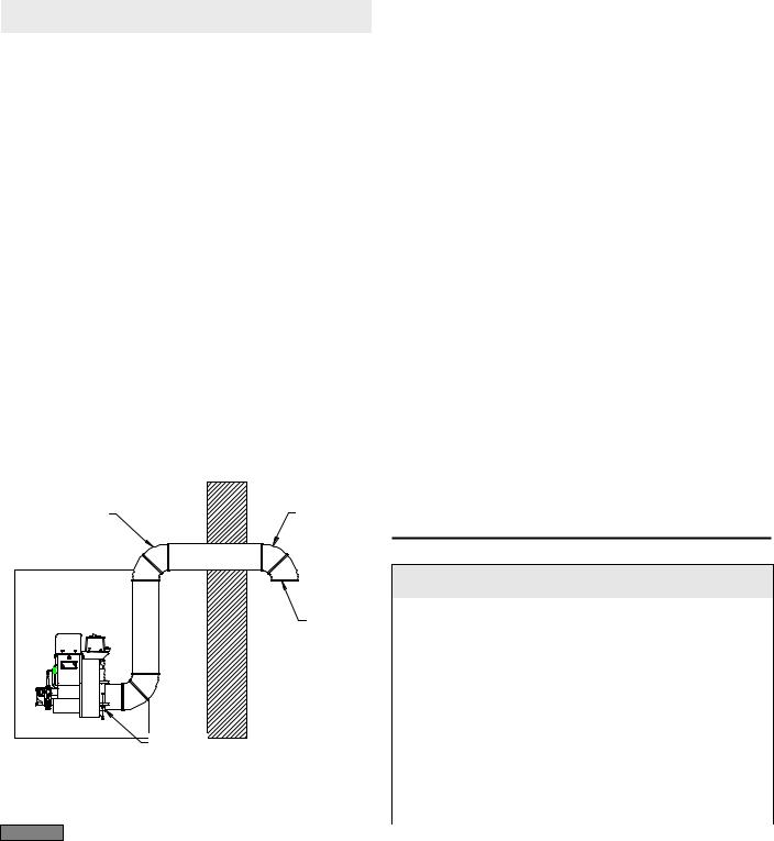
•AFII burners are equipped with a removable air inlet to allow use of a 4” duct to supply outside air for combustion. Do not exceed 70 equivalent feet. Allow 6 feet for each elbow.
1.Remove the inlet cover.
2.Insert 4" duct into the inlet ring.
3.Fasten duct into place using at least 3 sheet metal screws evenly spaced around the inlet ring. Refer to Figure 1.
4.Remove the barometric draft control unless it is in the same atmospheric pressure zone as the inlet.
On the outside of the home use a 90° elbow pointed downward with a 1/4" mesh screen over its opening. The air inlet elbow must be located above the snow line and in such a way as to prevent leaves and/or other debris from blocking the air flow. Such debris will prevent proper operation of the burner. Refer to local codes for proper location of inlet.
Figure 1 – Outside air connection
4 IN. DUCT |
AIR |
|
INLET |
|
ELBOW |
¼” MESH SCREEN
INLET |
|
RING |
SK8810 |
|
Combustion air supply
See NFPA Standard 31 for complete details.
WARNING If the burner is not supplied with a reliable combustion air source, the burner cannot properly burn the fuel. This would result in incomplete combustion, causing sooting and possible emission of carbon monoxide. Severe personal injury, death or substantial property damage could occur.
Appliance located in confined space
The confined space should have two (2) permanent openings: one near the top of the enclosure and one near the bottom of the enclosure. Each opening shall have a free area of not less than (1) one square inch per 1,000 BTU’s per hour of the total input rating of all appliances within the enclosure. The openings shall have free access to the building interior, which should have adequate infiltration from the outside.
Clearances to burner and appliance
•Provide space around burner and appliance for easy service and maintenance.
•Check minimum clearances against those shown by the appliance manufacturer and by applicable building codes.
Combustion chamber — Burner retrofitting
Verify that the appliance combustion chamber provides at least the minimum dimensions given in Table 2.
CAUTION |
When retrofitting an appliance that has an unlined stainless |
|
steel combustion chamber, chamber burnout could result from the use of a high performance burner. Protect the chamber from high temperatures through the use of "wet-pac" or a similar ceramic liner. Some equipment may utilize a stainless steel combustion chamber that has been designed and tested by the manufacturer for use with a flame retention burner, therefore ceramic protection would not be necessary. Refer to appliance manufacturer’s instructions. Failure to comply could result in damage to heating equipment.
Table 2 – Minimum combustion chamber dimensions
Chamber dimension (inches)
Firing |
Round |
Rectangular |
|
Floor to |
|
rate |
|
|
Height |
||
I.D. |
|
|
nozzle |
||
(gph) |
Width |
Length |
|
||
|
|
|
|||
|
|
|
|
|
|
0.50 |
8 |
7 |
8 |
12 |
5-6 |
|
|
|
|
|
|
0.75 |
9 |
8 |
9 |
12 |
5-6 |
|
|
|
|
|
|
1.00 |
10 |
9 |
10 |
12 ½ |
5-6 |
|
|
|
|
|
|
1.25 |
11 |
10 |
11 |
12 ½ |
5-6 |
|
|
|
|
|
|
1.50 |
12 |
11 |
12 |
13 |
6-7 |
|
|
|
|
|
|
4
 Loading...