

Page 1
www.basler.com
+1 618.654.2341 (USA)
info@basler.com
INTRODUCTION
BE3 phase sequence relays detect reverse phase
connections of lines, transformers, motors, and gener ators.
An incorrect phase sequence causes the BE3-47 to deenergize, preventing the starting of incorrectly connected
equipment.
SPECIFICATIONS
Inputs
All units are self powered.
Nominal Voltage: 120 Vac, 240 Vac, 380 Vac, or
480 Vac
Overload Withstand: 1.25 times nominal continuously.
2 times nominal for 3 s.
Frequency: 50, 60, or 400 Hz
Burden: <3 VA
Outputs
Relay Type: D.P.D.T.
AC Rating: 250 V, 5 A, non-resistive,
1200 VA
DC Rating: 125 V, 1 A, resistive, 120 W
Mechanical Life: 5 million operations
Temperature
Operating Temperature: 0°C (32°F) to 60°C (140°F)
Functional Temperature: –25°C (–13°F) to 70°C (158°F)
Storage Temperature: –40°C (–40°F) to 70°C (158°F)
Temperature Coefficient: 0.03% per °C (300 ppm/°C)
Humidity
Relative Humidity: 95% non-condensing
Physical
Mounting: DIN rail 1.38” by 0.29” (35 mm by
7.5 mm)
Case: Complies with IEC 529, DIN
40050, BS 5490
Case Material: Complies with UL 94VO
Weight: 0.88 lb (0.4 kg)
Size: 2.17” wide (55 mm)
Agency
cULus listed to UL 508 and CSA C22.2 No. 14
CE compliant
GOST-R certified per the relevant standards of Gosstandart
of Russia
Model
BE3-47
OPERATION
The BE3-47 output relay energizes when the relay senses a
nominal three-phase input with the correct phase sequence.
The output relay de-energizes when an input with an
incorrect phase sequence is detected. Two LED indicators
are provided. The green 123 LED lights to indicate correct
phase sequence. The red 321 LED lights to indicate
incorrect phase sequence.
INSTALLATION
BE3 phase sequence relays are designed for mounting on
standard DIN rails that comply to DIN-EN 50022. Mounting
involves hooking the top edge of the cutout on the base of
the case over one edge of the DIN rail. The opposite side of
the cutout containing the release clip is then pushed over
the opposite side of the DIN rail. To remove or reposition the
relay, lever the release clip and move the relay as required.
BE3 relays should be installed in a dry, vibration-free
location where the ambient temperature does not exceed
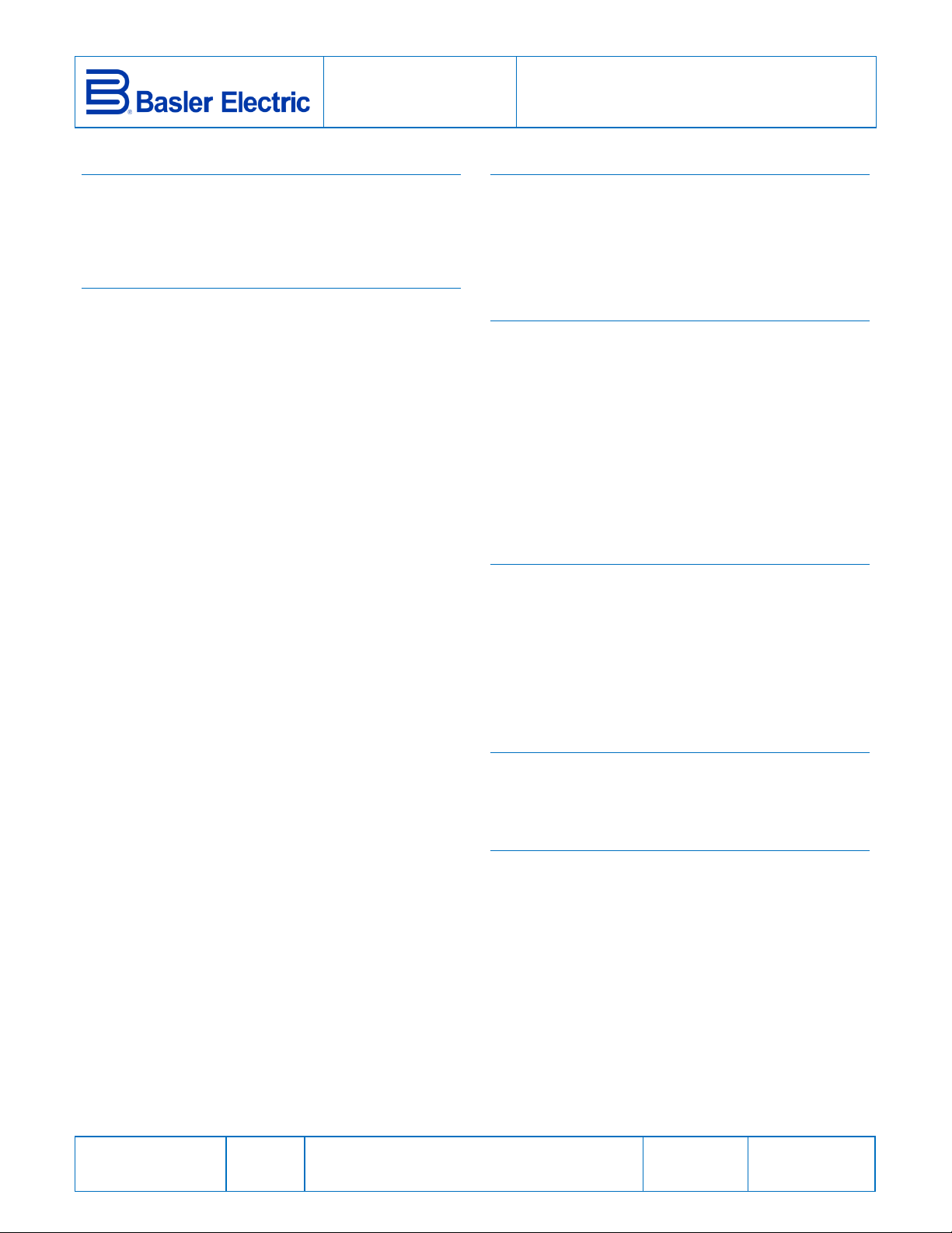
the operating temperature range. Connections to the relay
should be made using wire that meets applicable codes and
is properly sized for the application. Figure 1 shows the
terminal connections for the BE3-47 relay.
CALIBRATION
The BE3-47 has no adjustments and no cali bration is
necessary. The following procedure may be used to verify
proper operation.
1. Apply a nominal, three-phase input with the correct
phase sequence. The output relay should energize and
the green 123 LED should light.
2. Apply a nominal, three-phase input with an incorrect
phase sequence. The output relay should de-energize
and the red 321 LED should light.
MAINTENANCE
BE3 relays are solid-state devices that require no
maintenance. In the event that your relay requires repair,
contact Basler Electric, Highland, IL, USA for return
authorization.
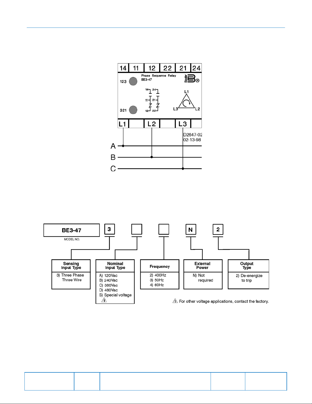
ORDERING INFORMATION
Figure 2 shows the BE3 phase sequence relay style chart.
Publication
9320200990
Revision
D
Instructions
Date
04/14
Copyright
2014
Page 2
FIGURES
Figure 1. BE3-47 Phase Sequence Connections
Publication
9320200990
Revision
D
Figure 2. BE3-47 Style Number Identification Chart
Instructions
Date
04/14
Page
2 of 2
 Loading...