


Portable Combustion Analyzer
Operation and Maintenance Manual
Instruction 0024-9472
Rev. 2 – August 2012
Product Leadership • Training • Service • Reliability

PCA 3 Manual
WARRANTY POLICY
Bacharach, Inc. warrants to Buyer that at the time of delivery this Product will be free from defects in material and manufacture and will conform substantially to Bacharach Inc.’s applicable specifications. Bacharach’s liability and Buyer’s remedy under this warranty are limited to the repair or replacement, at Bacharach’s option, of this Product or parts thereof returned to Seller at the factory of manufacture and shown to Bacharach Inc.’s reasonable satisfaction to have been defective; provided that written notice of the defect shall have been given by Buyer to Bacharach Inc. within two (2) years after the date of delivery of this Product by Bacharach, Inc. The Oxygen (O2) sensor has a limited warranty of one (1) year. Routine service and calibration are excluded from this warranty.
Bacharach, Inc. warrants to Buyer that it will convey good title to this Product. Bacharach’s liability and Buyer’s remedy under this warranty of title are limited to the removal of any title defects or, at the election of Bacharach, to the replacement of this Product or parts thereof that are defective in title.
THE FOREGOING WARRANTIES ARE EXCLUSIVE AND ARE GIVEN AND ACCEPTED IN LIEU OF (I) ANY AND ALL OTHER WARRANTIES, EXPRESS OR IMPLIED, INCLUDING WITHOUT LIMITATION THE IMPLIED WARRANTIES OF MERCHANTABILITY AND FITNESS FOR A PARTICULAR PURPOSE: AND (II) ANY OBLIGATION, LIABILITY, RIGHT, CLAIM OR REMEDY IN CONTRACT OR TORT, WHETHER OR NOT ARISING FROM BACHARACH’S NEGLIGENCE, ACTUAL OR IMPLIED. The remedies of the Buyer shall be limited to those provided herein to the exclusion of any and all other remedies including, without limitation incidental or consequential damages. No agreement varying or extending the foregoing warranties, remedies or this limitation will be binding upon Bacharach, Inc. unless in writing, signed by a duly authorized officer of Bacharach.
Register Your Warranty by Visiting
www.MyBacharach.com
NOTICE
Product improvements and enhancements are continuous, therefore the specifications and information contained in this document may change without notice.
Bacharach, Inc. shall not be liable for errors contained herein or for incidental or consequential damages in connection with the furnishing, performance, or use of this material.
No part of this document may be photocopied, reproduced, or translated to another language without the prior written consent of Bacharach, Inc.
Copyright © 2012, Bacharach, Inc., all rights reserved.
BACHARACH, PCA, B-SMART, and FYRITE are registered trademarks of Bacharach, Inc. All other trademarks, trade names, service marks and logos referenced herein belong to their respective companies.
2 |
0024-9472 Rev 2 |

|
|
PCA 3 Manual |
|
TABLE OF CONTENTS |
|
CHAPTER 1. |
INTRODUCTION ........................................................................ |
7 |
1.1. About This Manual ....................................................................................... |
7 |
|
1.2. Conventions ................................................................................................. |
7 |
|
1.3. Safety ........................................................................................................... |
|
7 |
1.4. General Description ..................................................................................... |
9 |
|
1.5. Operation Overview..................................................................................... |
9 |
|
1.5.1. Turning On the PCA®3 ...................................................................... |
9 |
|
1.5.2. The Combustion Test..................................................................... |
10 |
|
1.5.3. Turning Off the PCA®3.................................................................... |
10 |
|
1.6. Features and Benefits ................................................................................ |
11 |
|
1.7. Sales Combo and Model Configurations .................................................... |
12 |
|
1.8. Specifications ............................................................................................. |
13 |
|
CHAPTER 2. |
HARDWARE ............................................................................ |
15 |
2.1. Overview .................................................................................................... |
|
15 |
2.2. Front Panel Buttons ................................................................................... |
16 |
|
2.3. Backlit Display ............................................................................................ |
17 |
|
2.4. Battery Compartment ................................................................................ |
17 |
|
2.5. AC Adapter Connector (POWER)................................................................ |
17 |
|
2.6. Probe Connectors (Gas, Pressure, T-Stack)................................................ |
18 |
|
2.7. Differential Pressure Connector (∆P)......................................................... |
19 |
|
2.8. Primary Air Thermocouple Connector (T-AIR) ........................................... |
19 |
|
2.9. Computer Interface (USB).......................................................................... |
19 |
|
2.10. Wireless Printer Port (IrDA) ..................................................................... |
19 |
|
2.11. Options Connector (OPT) ......................................................................... |
19 |
|
CHAPTER 3. |
INITIAL SETUP ......................................................................... |
20 |
3.1. Overview .................................................................................................... |
|
20 |
3.2. Power ......................................................................................................... |
|
20 |
3.3. Connecting the Probe and Hose Assembly ................................................ |
21 |
|
3.4. Preparing to Configure the PCA®3.............................................................. |
21 |
|
CHAPTER 4. |
CONFIGURATION PROCEDURES .............................................. |
23 |
4.1. Default Operating Parameters ................................................................... |
23 |
|
4.2. Fuel Selection ............................................................................................. |
23 |
|
4.3. Auto/Manual CO Zero Selections............................................................... |
24 |
|
4.4. Temperature Units Selection ..................................................................... |
25 |
|
4.5. Pressure Units Selection ............................................................................ |
26 |
|
4.6. Pollution Units Selection ............................................................................ |
27 |
|
0024-9472 Rev 2 |
3 |

PCA 3 Manual
4.7. Date Setup.................................................................................................. |
27 |
4.8. Time Setup ................................................................................................. |
28 |
4.9. O2 Reference Setup .................................................................................... |
29 |
4.10. Print Pressure Selection ........................................................................... |
30 |
4.11. Zoom Display Selection ............................................................................ |
30 |
4.12. Logging Selection ..................................................................................... |
31 |
4.13. Button Sound Selection............................................................................ |
31 |
4.14. Test ID Information .................................................................................. |
32 |
4.14.1. Entering or Editing a Test ID ........................................................ |
32 |
4.14.2. Selecting a Test ID ....................................................................... |
33 |
4.14.3. Clearing Test ID Information........................................................ |
33 |
4.15. User Name ............................................................................................... |
34 |
4.15.1. Entering a User Name.................................................................. |
34 |
4.15.2. Clearing a User Name .................................................................. |
35 |
4.16. Language .................................................................................................. |
36 |
4.17. Cal Reminder Period ................................................................................ |
36 |
4.18. Run/Hold Screen Format.......................................................................... |
37 |
CHAPTER 5. OPERATION ............................................................................ |
40 |
5.1. Operating Tips............................................................................................ |
40 |
5.2. Turning On the Analyzer ............................................................................ |
41 |
5.3. Low Battery Alarm ..................................................................................... |
42 |
5.4. Locating Sampling Points ........................................................................... |
42 |
5.5. Performing a Combustion Test .................................................................. |
43 |
5.6. Selecting a Pressure Label.......................................................................... |
45 |
5.7. Temperature Label Selection and Measurement ...................................... |
46 |
5.8. Performing a Draft / Pressure Measurement ............................................ |
47 |
5.9. Saving Test Data......................................................................................... |
48 |
5.10. Ending a Combustion Test........................................................................ |
49 |
5.11. Emptying the Water Trap......................................................................... |
49 |
5.12. Data Logging............................................................................................. |
50 |
5.12.1. Overview...................................................................................... |
50 |
5.12.2. Turning On Data Logging ............................................................. |
51 |
5.12.3. Setting the Logging Interval and Duration................................... |
52 |
5.12.4. Starting the Data Logging Process ............................................... |
53 |
5.12.5. Ending the Data Logging Process................................................. |
53 |
5.13. Memory Functions ................................................................................... |
54 |
5.13.1. Overview...................................................................................... |
54 |
5.13.2. Recalling Combustion Test Data.................................................. |
54 |
5.13.3. Recalling Logged Test Data.......................................................... |
55 |
5.13.4. Clearing Memory ......................................................................... |
56 |
4 |
0024-9472 Rev 2 |

|
|
PCA 3 Manual |
5.14. Downloading Stored Data to a Computer................................................ |
57 |
|
5.15. Importing Saved Data into a Spreadsheet ............................................... |
57 |
|
5.16. Printing Test Data..................................................................................... |
59 |
|
5.17. Turning Off the Analyzer and Purging...................................................... |
61 |
|
CHAPTER 6. |
CALIBRATION .......................................................................... |
62 |
6.1. B-Smart Sensors ......................................................................................... |
62 |
|
6.2. Starting a Calibration ................................................................................. |
62 |
|
6.3. B-Smart® Sensor Replacement and Calibration.......................................... |
63 |
|
6.4. Pressure Sensor Calibration ....................................................................... |
64 |
|
6.4.1. Material Required.......................................................................... |
64 |
|
6.4.2. Procedure ...................................................................................... |
64 |
|
6.5. T-Stack Calibration ..................................................................................... |
65 |
|
6.5.1. Material Required.......................................................................... |
66 |
|
6.5.2. TS-Zero Procedure ......................................................................... |
66 |
|
6.5.3. TS-Span Procedure ........................................................................ |
67 |
|
6.6. T-Air Calibration ......................................................................................... |
67 |
|
6.6.1. Material Required.......................................................................... |
67 |
|
6.6.2. TA-Zero Procedure......................................................................... |
67 |
|
6.6.3. TA-Span Procedure ........................................................................ |
69 |
|
6.7. COLOW Sensor Calibration ........................................................................... |
69 |
|
6.7.1. Material Required.......................................................................... |
69 |
|
6.7.2. Procedure ...................................................................................... |
70 |
|
6.8. SO2 Sensor Calibration ............................................................................... |
72 |
|
6.8.1. Material Required.......................................................................... |
72 |
|
6.8.2. Procedure ...................................................................................... |
72 |
|
6.9. NO Sensor Calibration................................................................................ |
73 |
|
6.9.1. Material Required.......................................................................... |
73 |
|
6.9.2. Procedure ...................................................................................... |
73 |
|
6.10. NO2 Sensor Calibration............................................................................. |
74 |
|
6.10.1. Material Required........................................................................ |
74 |
|
6.10.2. Procedure .................................................................................... |
74 |
|
6.11. COHIGH Sensor Calibration......................................................................... |
76 |
|
6.11.1. Material Required........................................................................ |
76 |
|
6.11.2. Procedure .................................................................................... |
76 |
|
CHAPTER 7. |
MAINTENANCE ....................................................................... |
78 |
7.1. Overview |
.................................................................................................... |
78 |
7.2. PCA®3 Disassembly..................................................................................... |
78 |
|
7.2.1. Tools ...............................................................................Required |
78 |
|
7.2.2. Procedure ...................................................................................... |
78 |
|
0024-9472 Rev 2 |
5 |

PCA 3 Manual
7.3. Emptying the Water Trap Chamber ........................................................... |
83 |
|
7.4. Replacing the Filter Element ...................................................................... |
83 |
|
7.4.1. Material Required.......................................................................... |
83 |
|
7.4.2. Procedure ...................................................................................... |
83 |
|
7.5. Sensor Replacement .................................................................................. |
84 |
|
7.6. Nitric Oxide (NO) Sensor Battery Replacement ......................................... |
86 |
|
7.6.1. Material Required.......................................................................... |
86 |
|
7.6.2. Procedure ...................................................................................... |
86 |
|
7.7. Cleaning the Probe..................................................................................... |
87 |
|
7.7.1. Equipment Required...................................................................... |
87 |
|
7.7.2. Procedure ...................................................................................... |
87 |
|
CHAPTER 8. |
TROUBLESHOOTING ............................................................... |
88 |
8.1. Error Symbols............................................................................................. |
88 |
|
8.2. Diagnostics and Status Screens.................................................................. |
88 |
|
8.3. Accessing the Diagnostic Menu ................................................................. |
89 |
|
8.4. Accessing the Status Menu ........................................................................ |
89 |
|
8.5. Error Messages (After Warm-up)............................................................... |
89 |
|
8.6. Replacement Parts ..................................................................................... |
90 |
|
8.7. Accessories................................................................................................. |
93 |
|
8.8. Analyzer Repair .......................................................................................... |
95 |
|
8.9. Service Centers........................................................................................... |
95 |
|
CHAPTER 9. |
DECLARATION OF CONFORMITY ............................................. |
96 |
6 |
0024-9472 Rev 2 |
PCA 3 Manual
CHAPTER 1. INTRODUCTION
1.1. About This Manual
Thank you for investing in a Bacharach PCA®3 Combustion Analyzer. To assure operator safety and the proper use of the PCA®3, please read the contents of this manual for important information on the operation and maintenance of the analyzer.
1.2. Conventions
WARNING: A warning statement denotes a potential hazard associated with the use of this equipment. Failure to follow this information could result in serious personal injury or death.
CAUTION: A caution statement indicates a potentially hazardous situation which, if not avoided, may result in minor or moderate injury. Caution statements may also be used to alert against unsafe practices.
IMPORTANT: An important statement provides emphasis of an important feature, operation, etc. Failure to follow this information could void your warranty, result in improper operation, or cause equipment damage.
NOTE: A note statement provides emphasis of a feature, operation, practice, etc.
1.3. Safety
WARNING: This analyzer is not intended to be used as a safety device.
WARNING: When testing an appliance, a full visual inspection of the appliance should be performed to ensure its safe operation.
CAUTION: This analyzer is not intended to be used on a continuous basis.
0024-9472 Rev 2 |
7 |
PCA 3 Manual
CAUTION: Do not store instrument or its sensors with solvents or products that contain solvents.
CAUTION: Except for sensor and battery replacement, this analyzer should only be opened and/or serviced by authorized Bacharach personnel. Failure to comply may void the warranty.
HAZARDOUS AREA WARNING: This instrument has not been
designed to be intrinsically safe for use in areas classified as hazardous locations. For your safety, DO NOT use it in hazardous (classified) locations.
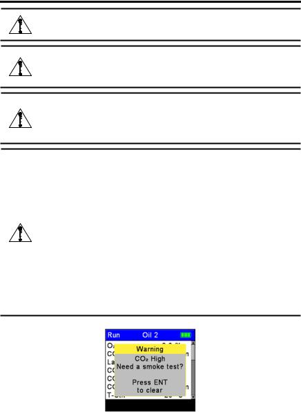
CAUTION: When the instrument is used in an inefficient furnace or boiler application where there is a high emission of soot, the probe’s sample filter may become clogged. Before every use check the filter to confirm that it is clean or replace it with a new filter.
To prevent this from occurring, a smoke test should be performed before operating under such conditions. This ensures that the furnace or boiler is burning at a level appropriate for the use of this instrument.
When the CO2 level exceeds the allowable threshold, a warning will appear prompting the user to consider performing a smoke test (see Figure 1-1). This screen is removed by pressing the ENT button. Once the warning is cleared, it will not be displayed again for that particular test. If a new test is started (by pressing the HOLD button), the warning will be displayed again if the limit has been exceeded.
Figure 1-1. High CO2 Warning
8 |
0024-9472 Rev 2 |
PCA 3 Manual
1.4. General Description
The PCA®3 is a commercial-grade hand-held combustion and emissions analyzer designed for on-demand sampling of light industrial, institutional, commercial and residential furnaces, appliances, and boilers.
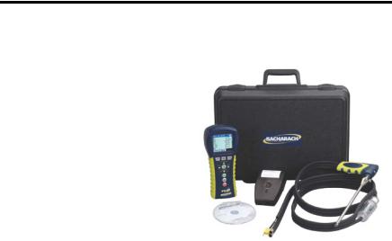
The basic instrument is supplied with a probe and hose assembly, instruction manual, factory calibrated smart sensors, 4 ‘AA’ alkaline batteries, boot, Fyrite® User Software, USB cable, and carrying case. Refer to Figure 1-2.
The PCA®3 can measure up to four |
|
gases simultaneously, so it is the |
|
perfect tool for service technicians, |
|
inspectors, and boiler contractors |
|
who need to determine combustion |
|
efficiency, excess air, stack gas O2 |
|
and CO levels, stack temperature, |
Figure 1-2. A Typical PCA®3 Kit |
draft, and differential pressure. |
The analyzer can also directly measure and display NO, NO2 and SO2 with the installation of the appropriate sensors. Combustion efficiency calculations can be conducted for a variety of fuels (see Specifications later in this chapter).
B-Smart® sensor technology allows a new sensor to be installed in the field without having to calibrate the analyzer with gas before use.
Advanced data storage and communication features allow the operator to store up to 500 individual combustion test records, which can later be recalled for viewing, printing, or downloading to a personal computer. In its data logging mode, the analyzer can store an additional 500 data logged records. The optional AC power adapter allows the analyzer to run for extended periods of time while data logging.
The optional sample conditioning probe is recommended when measuring NO2 and SO2 to ensure the highest degree of measurement accuracy.
A probe and hose assembly with an integral thermocouple and filter/water trap connect to the bottom of the analyzer, providing the means of drawing in gas samples and for measuring stack temperature and draft.
1.5. Operation Overview
1.5.1. Turning On the PCA®3
The PCA®3 is turned ON by pressing its red I/O button. A warm-up period of 60 seconds then begins, during which time the analyzer performs self diagnostics. At the end of the warm-up period, if no errors were detected the instrument will display the Combustion Test HOLD screen. If errors were detected, the message
0024-9472 Rev 2 |
9 |

PCA 3 Manual
“ERRORS DETECTED” is displayed along with a list of the errors. These errors must be corrected before proceeding with the combustion test.
Before starting a test be sure to select the fuel being burned. The default fuel selected is Natural Gas. Note that the name of the fuel being burned is indicated at the top of the run/hold screen.
1.5.2. The Combustion Test
To assure correct combustion efficiency calculations, the analyzer must know the burner’s primary-air temperature. The analyzer normally uses its internal temperature sensor for the primary-air temperature value, but this method is only acceptable if the burner is using ambient room air. If the burner is drawing in cold outside air, we recommend that the optional T-AIR thermocouple be used. This thermocouple plugs into the bottom of the analyzer and is placed in the burner’s primary-air stream.
Begin the combustion test by first inserting the analyzer’s probe tube into the stack-gas stream of the appliance under test, and then pressing the RUN/HOLD
button to display the Combustion Test RUN screen. The analyzer will begin to continuously monitor the stack temperature, %O2 and emission levels in the stack gas and then display measured and calculated values on its display. The recommended time required to achieve a stable measurement is a minimum of 3 minutes.
During a test, the COLOW sensor is protected from high CO levels by being automatically flushed with fresh air when the detected CO level exceeds 4,000 ppm. The analyzer will automatically start using its optional COHIGH sensor, if installed, at CO levels starting at 4,001 ppm, thus providing continuous CO readings up to 20,000 ppm.
A keypad backlight enables a user to read the keypad in dimly-lit areas. Turn the keypad backlight ON and OFF by briefly pressing the I/O button.
1.5.3. Turning Off the PCA®3
The analyzer is turned OFF by pressing and holding down the I/O button for at least 2 seconds. Note that there is a 5-second delay before the analyzer actually turns OFF, during which time the analyzer can be turned back ON by pressing the RUN/HOLD button. In addition, there is a gas-purge feature that keeps the analyzer’s pump running if the gas level inside the sensor chambers is abnormally high at shutdown. With the probe removed from the stack and sampling fresh air, the analyzer purges itself until the detected gas concentrations drop below predetermined levels.
10 |
0024-9472 Rev 2 |
PCA 3 Manual
1.6. Features and Benefits
•Powered by 4 ‘AA’ alkaline batteries or NiMH rechargeable batteries. An optional AC adapter provides extended operation.
•O2 and COLOW measurement standard. Optional measurement of up to two additional gases, including COHIGH, NO, NO2, or SO2.
•With the appropriate sensors installed, the analyzer optionally displays
pollution conversions for CO, NO, NO2, and SO2. Pollution conversions include ppm, #/MBTU, mg/m3, and g/GJ.
•B-Smart® sensor technology allows pre-calibrated sensors to be installed in
the field. Sensors are provided with data that can be entered through the PCA®3 software, or instrument calibration menus, for easy calibration.
•Automatic flushing of the COLOW sensor with fresh air if the CO level exceeds 4,000 ppm, thus protecting the COLOW sensor from high CO levels. To measure CO levels above 4,000 ppm, the analyzer automatically switches to its COHIGH sensor, if installed.
•Automatic purging of the gas-sample system if the detected gas levels are abnormally high when the analyzer is turned OFF.
•Displays temperatures in either °F or °C
•Displays pressure in either inwc, mb, Pa, or hPa
•Backlit color graphic LCD with zoom capabilities
•Low battery alarm
•Stores 500 individual combustion records, which can later be recalled for viewing, printing, or downloading to a personal computer. Stores an additional 500 data logged records.
•Wireless IrDA link for printing current and stored combustion records, pressure records, calibration data, and diagnostic data
•USB connectivity for downloading data to personal computer
•Field replaceable sensors and thermocouple
•Two year warranty on analyzer and all gas sensors except the O2 sensor which has a one (1) year warranty.
•Language options including English, French, and Spanish
•Custom Display Formats
•Calibration Reminders: PCA®3 can be configured to remind the user that calibration is past due.
•Auto/manual zeroing option allows the operator to select the start-up mode. Auto-zero determines the zero reading of the CO channel in fresh air and provides an offset for the CO measurements. Also, all sensing channels are automatically zeroed on ambient air when the analyzer is first turned ON. Manual zero is used to detect CO that may be present during start-up.
0024-9472 Rev 2 |
11 |

PCA 3 Manual
1.7. Sales Combo and Model Configurations
Sales Combo
(0024-xxxx)
Sales Combo Kit
(0024-xxxx)
Model Type
PCA®3 Only Part Number
(0024-xxxx)
8440 |
8441 |
8442 |
8443 |
8444 |
8445 |
8446 |
|
|
|
|
|
|
|
8447 |
8448 |
8449 |
8450 |
8451 |
8452 |
8453 |
|
|
|
|
|
|
|
225 |
235 |
245 |
255 |
265 |
275 |
285 |
|
|
|
|
|
|
|
7320 |
7321 |
7322 |
7323 |
7324 |
7325 |
7326 |
|
|
|
|
|
|
|
Measurements |
|
|
|
|
|
|
|
|
|
|
|
|
|
|
|
|
|
|
|
|
|
|
|
Oxygen (O2) |
• |
• |
• |
• |
• |
• |
• |
Stack Temperature |
• |
• |
• |
• |
• |
• |
• |
|
|
|
|
|
|
|
|
Primary/Ambient Air Temperature |
• |
• |
• |
• |
• |
• |
• |
|
|
|
|
|
|
|
|
Carbon Monoxide Low (COLOW) |
• |
• |
• |
• |
• |
• |
• |
Pressure/Draft |
• |
• |
• |
• |
• |
• |
• |
|
|
|
|
|
|
|
|
Carbon Monoxide High (COHIGH) |
|
|
• |
|
|
|
• |
Nitric Oxide (NO) |
|
• |
|
|
• |
• |
• |
|
|
|
|
|
|
|
|
Nitrogen Dioxide (NO2) |
|
|
|
|
• |
|
|
Sulfur Dioxide (SO2) |
|
|
|
• |
|
• |
|
Calculations |
|
|
|
|
|
|
|
|
|
|
|
|
|
|
|
Combustion Efficiency |
• |
• |
• |
• |
• |
• |
• |
|
|
|
|
|
|
|
|
Excess Air |
• |
• |
• |
• |
• |
• |
• |
|
|
|
|
|
|
|
|
Carbon Dioxide (CO2) |
• |
• |
• |
• |
• |
• |
• |
NOx (NOx = NO + NO2) |
|
|
|
|
• |
|
|
NOx referenced to % O2 |
|
|
|
|
• |
|
|
CO referenced to % O2 |
• |
• |
• |
• |
• |
• |
• |
NO referenced to % O2 |
|
• |
|
|
• |
• |
• |
NO2 referenced to % O2 |
|
|
|
|
• |
|
|
SO2 referenced to % O2 |
|
|
|
• |
|
• |
|
12 |
0024-9472 Rev 2 |

|
|
PCA 3 Manual |
|
1.8. Specifications |
|
|
|
|
|
Measurement (Based on Installed Sensors) |
Display Range |
|
Oxygen |
0.1 to 20.9% |
|
Stack Temperature |
-4 to 2,192 °F (-20 to 1,200 °C) |
|
Primary/Ambient Air Temperature |
-4 to 999 °F (-20 to 537 °C) |
|
Carbon Monoxide (CO) (H2 compensated) |
0 to 4,000 ppm |
|
Pressure/Draft |
±72” H2O (±179 mb) |
|
CO High Range |
4,001 to 20,000 ppm |
|
Nitric Oxide (NO) |
0 to 3,000 ppm |
|
Nitrogen Dioxide (NO2) |
0 to 500 ppm |
|
Sulfur Dioxide (SO2) |
0 to 5,000 ppm |
|
|
|
|
Calculated Value (Based on Installed Sensors) |
Display Range |
|
Combustion Efficiency |
0.1 to 100% |
|
Excess Air |
1 to 250% |
|
Carbon Dioxide (dry basis) |
0.1 to fuel-dependent max in % |
|
NOx (NOx = NO + NO2) |
0 to 3,500 ppm |
|
NOx referenced to %O2 |
0 to 9,999 ppm |
|
CO referenced to %O2 |
0 to 9,999 ppm |
|
NO referenced to %O2 |
0 to 9,999 ppm |
|
NO2 referenced to %O2 |
0 to 9,999 ppm |
|
SO2 referenced to %O2 |
0 to 9,999 ppm |
NOTE: Calculations are performed only when the measured oxygen level is below 16.0% and the stack temperature is below 2,000 °F (1,093 °C).
0024-9472 Rev 2 |
13 |

PCA 3 Manual
Reading |
Performance Accuracy |
|
O2 |
±0.3% O2 on practical concentrations of stack gas |
|
(mix of O2, CO2, and N2) |
||
|
||
CO |
Greater of ±5% of reading or ±10 ppm, between 0-2,000 ppm, |
|
±10% of reading between 2,001 and 20,000 ppm. |
||
|
||
NO |
Greater of ±5% of reading or 5 ppm |
|
NO2 |
Greater of ±5% of reading or ±5 ppm between 0-500 ppm |
|
SO2 |
Greater of ±5% of reading or ±10 ppm between 0-2,000 ppm |
|
|
±4 °F (±2 °C) between 32 and 255 °F (0 and 124 °C) |
|
Stack Gas Temp |
±6 °F between 256 and 480 °F (±3 °C between 125 and 249 °C) |
|
|
±8 °F between 481 and 752 °F (±4 °C between 250 and 400 °C) |
|
Primary/Ambient |
±2 °F between 32 and 212 °F (±1 °C between 0 and 100 °C) |
|
Air Temp |
||
|
||
|
±0.02 inches from -1 to 1 inwc; |
|
Pressure/Draft |
±2% of reading from -10 to 10 inwc; |
|
|
±3% of reading from -40 to 40 inwc |
|
System Flow Rate |
200 cc/min minimum |
|
with Probe |
||
|
General Specification |
|
|
Description |
||||
|
|
||||||
Dimensions (H x W x D) |
9.0 x 3.0 x 2.5 inches (22.9 x 7.6 x 6.3 cm) |
||||||
Weight |
|
Analyzer with Batteries: |
........................... |
1.4 lb (0.6 kg) |
|||
|
Probe/Hose Assembly: |
|
1.0 lb (0.5 kg) |
||||
|
|
|
|||||
|
|
• |
Natural Gas |
|
• |
Wood |
|
Fuels Available for |
• |
Coal |
|
• |
Kerosene |
||
• |
Oil #2 |
|
• |
Bagasse |
|||
Combustion Calculations |
|
||||||
• |
Oil #4 |
|
• |
Propane |
|||
|
|
|
|||||
|
|
• |
Oil #6 |
|
• |
Digester Gas |
|
Warm-up Time |
60 seconds (Sensors checked and auto zeroed) |
||||||
|
4 “AA” Batteries |
Alkaline:.............................. |
|
10 hours of operation (min) |
|||
Power |
(Disposable) |
NiMH Rechargeable: ................... |
|
Operating time varies |
|||
AC Adapter |
100-240 VAC; 50/60 Hz: |
Continuous use |
|||||
|
|||||||
|
(Optional) |
||||||
|
|
|
|
|
|
||
Operating Temperature |
Analyzer: ................................ |
|
32 to 104 °F (0 to 40 °C) |
||||
Probe Tip: |
|
|
1,472 °F (800 °C) Max. |
||||
|
|
|
|
||||
Operating Humidity |
Analyzer: ...................... |
|
15 to 90% RH, non-condensing |
||||
Operating Air Pressure |
Analyzer: ................................................... |
|
|
Atmospheric |
|||
Probe: |
10″ H2O (25 mb) draft max. at probe tip |
||||||
|
|
||||||
Memory |
|
500 complete combustion test records |
|||||
|
500 complete logged combustion test records |
||||||
|
|
||||||
Interfaces |
|
Printer:.......................... |
|
Infrared (IrDA) communications |
|||
|
Computer: |
|
USB 2.0 (mini-B connector) |
||||
|
|
|
|||||
14 |
0024-9472 Rev 2 |

PCA 3 Manual
CHAPTER 2. HARDWARE
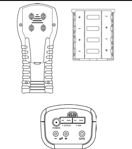
2.1. Overview
Figure 2-1. Front and Bottom Views Showing Key Components
0024-9472 Rev 2 |
15 |

PCA 3 Manual
2.2. Front Panel Buttons
The PCA®3 is controlled by various buttons, while a color graphic LCD (with automatic dimming feature) is used to display all combustion and emission test data and analyzer parameters. Descriptions of the front panel buttons are given below. Note that a button may perform multiple functions depending on the current screen that is displayed.
|
|
Transmits the data displayed on the screen to a printer |
|
|
|
|
through the IrDA communications port. |
|
F1 |
PAGE- |
When viewing the Memory or Logging Directory, each |
|
|
|
press of this button pages down through the directory. |
|
|
|
Holding this button down speeds up the paging process. |
|
|
MENU |
Displays the Main Menu. |
|
F2 |
ZERO |
When viewing the Pressure screen, this button zeros the |
|
|
pressure sensor to current atmospheric conditions. When |
|
|
|
|
viewing the Temperature screen, this button zeroes the |
|
|
|
temperature channel difference. |
|
|
SAVE |
Saves the data currently displayed on the LCD in |
|
|
|
memory. Up to 500 individual Combustion Test, |
|
|
|
Temperature, and Pressure records can be saved. After |
|
|
|
500 records have been saved, the memory must be |
|
F3 |
|
cleared to continue saving additional data. The analyzer |
|
|
|
will not overwrite old data. |
|
|
PAGE+ When viewing the Memory or Logging Directory, each |
|
|
|
|
press of this button pages through the directory. Holding |
|
|
|
this button speeds the paging process. |
|
▲ |
The arrow buttons move the cursor on the LCD. In screens that |
|
|
▼ |
require the entry of alphanumerical data, use the◄► buttons to |
|
|
◄ |
move cursor across the screen and then use the▲▼ buttons to |
|
|
► |
increment and decrement the data. When viewing a menu, use the |
|
|
|
◄► buttons to quickly move to the top and bottom of the menu. |
|
|
|
Selects a highlighted item. In addition, if changes were made to |
|
|
ENT |
one of the analyzer’s operating parameters (e.g., date, time, O2 |
|
|
reference, etc.), pressing this button confirms those changes and |
||
|
|
||
|
|
saves them in memory. |
|
|
|
|
|
|
|
Starts and stops a combustion test when the Combustion Test |
|
|
|
screen is displayed. Pressing this button in any other screen |
|
|
RUN/ |
returns the analyzer to the Combustion Test HOLD screen. |
|
|
HOLD |
Pressing this button during the 5 second turn-off-delay period will |
|
|
|
abort the turn-off process and also return the analyzer to the |
|
|
|
Combustion Test HOLD screen. |
|
|
|
Displays a previously viewed screen. In addition, if changes were |
|
|
|
made to one of the analyzer’s operating parameters (e.g., date, |
|
|
ESC |
time, O2 |
reference, etc.), pressing this button aborts those |
|
|
changes, restores the old values, and then displays the previously |
|
|
|
viewed screen. |
|
|
I/O |
Turns the analyzer ON and OFF, and is also used to turn the |
|
|
keypad LEDs ON and OFF. |
||
|
|
||
|
|
|
|
16 |
0024-9472 Rev 2 |
PCA 3 Manual
For example, the functions of the F1, F2, and F3 buttons are defined by labels appearing above them on the LCD. The labels that appear depend on the functions that can be performed in the particular screen being displayed.
NOTE: A keypad backlight enables a user to read the keypad in dimly-lit areas. Turn the keypad backlight ON and OFF by briefly pressing the I/O button.
NOTE: When the analyzer is turned OFF, there is a 5-second delay, during which time an operator can keep the analyzer turned ON by pressing the RUN / HOLD button. Also note that if the measured emission levels are above predetermined limits at the time the instrument is turned OFF, the pump is automatically started and purges the sensor compartment with fresh air until the gas levels inside the analyzer are reduced. If desired, the purging process can be aborted by again pressing the I/O button, though it is not recommended.
2.3. Backlit Display
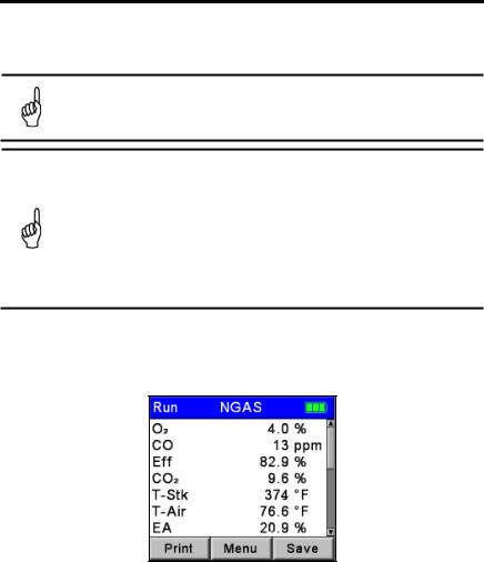
A large backlit color graphic display shows multiple combustion test values simultaneously, and includes a zoom capability that provides extra large text.
Figure 2-2. Sample Display
2.4. Battery Compartment
The PCA®3 is powered by either its four internal batteries or by an optional AC power adapter that operates from any convenient source of 100–240 VAC, 50/60 Hz power. Batteries may be either disposable alkaline or rechargeable NiMH.
2.5. AC Adapter Connector (POWER)
The AC power adapter P/N 0024-1254 can be used as an external power supply, which will run the analyzer on a continuous basis. It uses 100-240 VAC at 50/60 Hz.
0024-9472 Rev 2 |
17 |
PCA 3 Manual
Figure 2-3. Battery Compartment
Figure 2-4. Bottom View Showing Connectors
2.6. Probe Connectors (Gas, Pressure, T-Stack)
The probe and hose assembly are connected to the analyzer by way of the following connectors.
•Stack-gas thermocouple to the analyzer’s T-STACK connector
•Stack-gas hose to the analyzer’s GAS connector
•Draft hose to the analyzer’s +∆P connector
Observe that the probe connectors are of different sizes and shapes, which prevents incorrect connection to their associated connectors on the analyzer. See Figure 2-5.
18 |
0024-9472 Rev 2 |
PCA 3 Manual
Figure 2-5. Probe Connectors GAS, +∆P, and T-STACK
2.7. Differential Pressure Connector (∆P)
Draft is measured by connecting the probe’s draft hose to the +∆P fitting, while leaving the -∆P fitting open to the atmosphere. See Figure 2-5.
In addition to measuring draft, the “+” and “-” ∆P fittings can also be used to measure the differential pressure between two areas by first connecting a hose (P/N 0024-1103) to the -∆P fitting, and then inserting the open end of this hose into the area being used as the reference pressure. The analyzer’s probe is then inserted into the area where differential pressure is to be measured.
2.8. Primary Air Thermocouple Connector (T-AIR)
If thermocouple P/N 0104-1797 (10 feet long) or Utility Wand P/N 0104-1799 (12-inch ridged probe with handle and 5 foot coiled cable) is to be used to measure the burner’s primary air temperature, then connect either of these thermocouples to the analyzer’s T-AIR connector. See Figure 3-2 on page 22.
2.9. Computer Interface (USB)
Data stored in the analyzer’s memory can be downloaded to a personal computer by connecting USB data cable P/N 0104-4032 between the USB ports of the computer and analyzer. The PCA®3’s USB port is on its right side. See Figure 2-1 on page 15.
2.10. Wireless Printer Port (IrDA)
Data that has been stored in the analyzer’s memory can be printed on a compatible IrDA (Infrared data associated) wireless printer by aligning their IrDA communication ports. The IrDA port of the PCA®3 is located at the top of the device. See Figure 2-1 on page 15.
2.11. Options Connector (OPT)
The options connector is used for optional external measurement features. Refer to Figure 3-2 on page 22.
0024-9472 Rev 2 |
19 |
PCA 3 Manual
CHAPTER 3. INITIAL SETUP
3.1. Overview
Before configuring or using the PCA®3, you MUST:
•provide power
•connect the probe and hose assembly.
3.2.Power
Three options are available to power the PCA®3:
•disposable alkaline batteries
•rechargeable NiMH batteries
•AC power adapter.
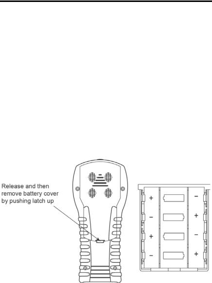
If you are using either alkaline or NiMH rechargeable batteries to power the analyzer, follow the instructions below to install or replace the batteries.
•Remove the battery cover from back of unit (Figure 3-1).
•Remove (and properly dispose of) any old batteries.
•Install a set of four ‘AA’ alkaline or NiMH batteries, per the “+” and “-” markings inside the battery compartment.
•Replace the battery cover.
Figure 3-1. Battery Cover and Compartment
The AC power adapter is capable of powering the analyzer on a continuous basis. The adapter plugs into an appropriate 100-240 VAC, 50/60 Hz wall outlet, and produces an output of +6 VDC. The adapter’s output connector plugs into the analyzer’s POWER jack located on the bottom of the unit (refer to Figure 3-2 on page 22).
20 |
0024-9472 Rev 2 |
PCA 3 Manual
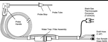
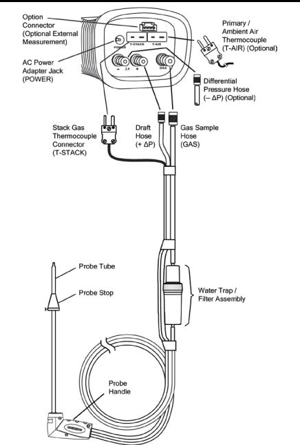
3.3. Connecting the Probe and Hose Assembly
To attach the probe and hose assembly to the analyzer follow the steps below and refer to Figure 3-2 on page 22.
1.Push the gas sample hose connector, the larger of the two connectors (giving a slight twist), onto the analyzer’s GAS fitting.
2.Push the draft hose connector, the smaller connector (giving a slight twist), onto the analyzers +∆P fitting.
3.Push the stack gas thermocouple connector into the T-STACK jack (connector fits in only one way).
4.Push the optional primary/ambient air thermocouple into the T-AIR jack (connector fits in only one way).
IMPORTANT: To assure the accurate calculation of combustion efficiency, the optional primary/ambient air thermocouple must be used when the burner’s primary-air temperature is not the same as the room temperature.
5.Inspect all hoses for cracks. If any hose is found to be defective, replace the entire probe and hose assembly. Check that the water trap is empty, and the filter is not dirty or saturated with water.
3.4.Preparing to Configure the PCA®3
After initial setup is complete, turn on the PCA®3. For detailed power-up instructions, refer to Turning On the PCA®3 on pages 9 and 41. You are now ready to configure your PCA®3 for your particular application and to your particular preferences. Refer to Configuration Procedures on page 23. You configure the PCA®3 by navigating the menus and changing key parameter values. It may be helpful to review Front Panel Buttons on page 16 in preparation for navigating the menu interface of the PCA®3.
0024-9472 Rev 2 |
21 |
PCA 3 Manual
Figure 3-2. Connecting the Probe to the Analyzer
22 |
0024-9472 Rev 2 |

PCA 3 Manual
CHAPTER 4. CONFIGURATION PROCEDURES
4.1. Default Operating Parameters
The PCA®3 is set up at the factory for the following operating parameters. To change any of these parameters, perform the associated procedure that follows.
Parameter |
Factory Default |
To Change Value, See… |
|
Fuel |
Natural Gas |
Page 23 |
|
Auto/Manual CO Zero |
Auto Zero |
Page 24 |
|
Temperature Units |
°F |
Page 25 |
|
Pressure Units |
Inches of Water Column (inwc) |
Page 26 |
|
Pollution Units |
ppm |
Page 27 |
|
Date |
Current MM/DD/YY |
Page 27 |
|
Time |
Current EST HH:MM AM/PM |
Page 28 |
|
O2 Reference |
0% |
Page 29 |
|
Print Pressure |
No |
Page 30 |
|
Zoom |
Standard |
Page 30 |
|
Logging |
No |
Page 31 |
|
Button Sound |
On |
Page 31 |
|
Test ID Information |
<blank> |
Page 32 |
|
User Name |
<blank> |
Page 34 |
|
Language |
English |
Page 36 |
|
Calibration Reminder |
Never |
Page 36 |
|
Run/Hold Screen |
See page 37 for default |
Page 37 |
|
Format |
|||
|
|
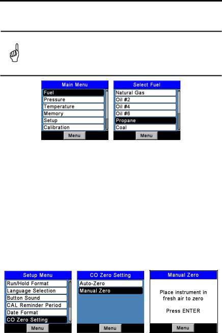
4.2. Fuel Selection
To assure the accurate calculation of combustion efficiency, select the fuel being burned as follows.
1.Display the MAIN MENU by pressing the MENU (F2) button. If necessary, press ESC until MENU appears above F2.
2.Use the ▲▼ buttons to highlight FUEL and then press ENT to display the FUEL MENU.
3.Use the ▲▼ buttons to scroll through the list of available fuels until the desired fuel is highlighted. In the example shown, PROPANE has been selected (If custom fuels are added, they will be displayed at the bottom of the list).
NOTE: Use the ◄► buttons to quickly scroll to the bottom and top of the list.
0024-9472 Rev 2 |
23 |
PCA 3 Manual
4.Press ENT to save the selection and display the Combustion Test HOLD screen. Observe that the name of the selected fuel should now appear at the top of the screen.
NOTE: In addition to the standard fuels programmed into the PCA®3, Bacharach can develop custom fuel codes based on the customers specific needs. The PCA®3 can be programmed with 2 additional fuels which can be added to the instrument using the Fyrite User Software (FUS). Consult factory for price and delivery.
Figure 4-1. Fuel Selection
4.3. Auto/Manual CO Zero Selections
Select how the PCA®3 performs a zero function.
1.Display the MAIN MENU by pressing the MENU (F2) button. If necessary, press ESC until MENU appears above F2.
2.Use the ▲▼ buttons to highlight SETUP, and then press ENT to display the SETUP MENU.
3.Use the ▲▼ buttons to highlight CO Zero Setting, and then press ENT to display the CO ZERO SETTING MENU.
4.Use the ▲▼ buttons to highlight the desired zeroing option (Manual or
Auto-Zero). In the example shown, Manual Zero has been selected.
5.Place the instrument in fresh air to zero, and press ENT to start a 60second count down.
6.Press ENT to save and re-display the SETUP MENU.
Figure 4-2. Auto/Manual Zero Selection
24 |
0024-9472 Rev 2 |

PCA 3 Manual
NOTE: The PCA®3 performs a zero function during warm-up. Among other purposes, an auto-zero determines the “zero reading” of the CO channel in fresh air and provides an offset for the CO measurement. A manual zero detects background CO during startup.
Manual Zero: When the CO channel is set to manual zero, the analyzer does not zero the CO sensor to ambient conditions during start up. In this mode, the “fresh air zero” established during manual mode setup is stored in memory and used for the calculation of CO.
Auto Zero: |
When the CO channel is set to auto zero, the CO sensor is zeroed |
|
to the ambient CO level during start up. Important: When using |
|
this mode, the analyzer must be turned ON in fresh air; otherwise, |
|
incorrect CO readings will occur. |
Auto Zero determines the zero reading of the CO channel in fresh air and provides an offset for the CO measurements. Manual zero is used to detect CO that may be present during start-up. The auto/manual zeroing option allows the operator to select the start-up mode. It is selectable from the CO Zero Setting of the Setup Menu.
NOTE: Both methods take the user through a 60-second count down to establish a new zero. The manual mode establishes a fresh air zero and stores it for use during instrument startup.
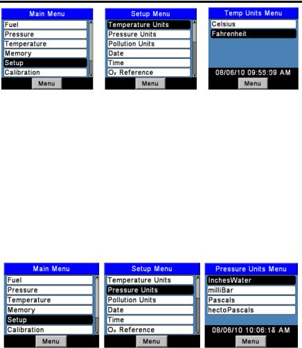
4.4. Temperature Units Selection
Select to display temperature in either °F or °C as follows.
1.Display the MAIN MENU by pressing the MENU (F2) button. If necessary, press ESC until MENU appears above F2.
2.Use the ▲▼ buttons to highlight SETUP, and then press ENT to display the SETUP MENU.
3.Use the ▲▼ buttons to highlight TEMP UNITS, and then press ENT to display the TEMP UNITS MENU.
4.Use the ▲▼ buttons to highlight the desired temperature units. In the example shown, Fahrenheit has been selected.
5.Press ENT to save the selection and re-display the SETUP MENU.
0024-9472 Rev 2 |
25 |
PCA 3 Manual
Figure 4-3. Temperature Units Selection
4.5. Pressure Units Selection
Select to display pressure in Inches of Water Column (inwc), millibar (mb), Pascals (Pa), or hectoPascals (hPa) as follows.
1.Display the MAIN MENU by pressing the MENU (F2) button. If necessary, press ESC until MENU appears above F2.
2.Use the ▲▼ buttons to highlight SETUP, and then press ENT to display the SETUP MENU.
3.Use the ▲▼ buttons to highlight PRESSURE UNITS, and then press
ENT to display the PRESSURE UNITS MENU.
4.Use the▲▼ buttons to high light the desired pressure units. In the example shown, InchesWater has been selected.
5.Press ENT to save the selection and re-display the SETUP MENU.
Figure 4-4. Pressure Units Selection
26 |
0024-9472 Rev 2 |
PCA 3 Manual
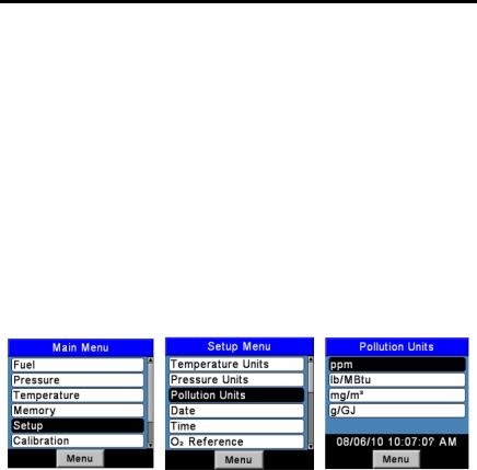
4.6. Pollution Units Selection
The PCA®3 is capable of converting the measured ppm levels of CO, NO, NO2, and SO2 to various pollution units using CFR40 Part 60 emission factors. Note that the pollution unit conversions for NO, NO2 and NOx are based on the molecular weight of NO2.
Configure the PCA®3 to display pollution units in parts per million (ppm), pounds of pollutant per million BTU (#/Mbtu), milligrams of pollutant per cubic meter of gas (mg/m3), or grams of pollutant per gigajoule (g/GJ) as follows.
1.Display the MAIN MENU by pressing the MENU (F2) button. If necessary, press ESC until MENU appears above F2.
2.Use the ▲▼ buttons to highlight SETUP, and then press ENT to display the SETUP MENU.
3.Use the ▲▼ buttons to highlight POLLUTION UNITS, and then press
ENT to display the POLLUTION UNITS MENU.
4.Use the▲▼ buttons to highlight the desired pollution units. In th e example shown, ppm has been selected.
5.Press ENT to save the selection and re-display the SETUP MENU.
Figure 4-5. Pollution Units Selection
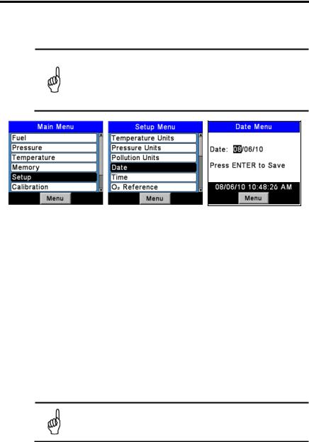
4.7. Date Setup
The date is stored in the format: MM/DD/YY. Its value is part of the date and time stamp that is saved along with each combustion test record. Set the analyzer’s internal clock to the current date as follows.
1.Display the MAIN MENU by pressing the MENU (F2) button. If necessary, press ESC until MENU appears above F2.
2.Use the ▲▼ buttons to highlight SETUP, and then press ENT to display the SETUP MENU.
3.Use the ▲▼ buttons to highlight DATE, and then press ENT to display the DATE MENU.
4.First use the ◄► buttons to move the cursor across the screen until it is over the digit to be changed, and then press the▲▼ buttons until the desired value is displayed.
0024-9472 Rev 2 |
27 |
PCA 3 Manual
5.Repeat Step 4 until the values for month, day, and year have been set.
6.Press ENT to save the selection and re-display the SETUP MENU, or press ESC to abort this procedure and retain the old date values.
NOTE: The real time clock is powered by the main batteries and is maintained by a coin cell battery on the Main PCB in the absence of batteries. Bacharach recommends changing the coin cell (P/N 0204-0020) every 5 years.
Figure 4-6. Date Setup
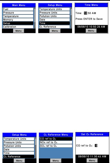
4.8. Time Setup
The time is stored in the format: hh:mm:ss AM/PM. Its value is part of the date and time stamp that is saved along with each combustion test record. Set the analyzer’s internal clock to the current time as follows.
1.Display the MAIN MENU by pressing the MENU (F2) button. If necessary, press ESC until MENU appears above F2.
2.Use the ▲▼ buttons to highlight SETUP, and then press ENT to display the SETUP MENU.
3.Use the ▲▼ buttons to highlight TIME, and then press ENT to display the TIME MENU.
4.First use the ◄► buttons to move the cursor across the screen until it is over the digit to be changed, and then press the▲▼ buttons until the desired value is displayed.
5.Repeat Step 4 until values for hour, minute, and meridian are set.
NOTE: The value for seconds cannot be entered, but is displayed and stored as part of the combustion test record.
6.Press ENT to save the displayed time values and re-display the SETUP MENU, or press ESC to abort and retain the old time values.
28 |
0024-9472 Rev 2 |
PCA 3 Manual
Figure 4-7. Time Setup
4.9. O2 Reference Setup
The measured values of CO, NOx, and SO2 can be individually referenced to a specific O2 percentage of between 0 and 15%. Individually set up the O2 reference value for each of the above gases as follows.
1.Display the MAIN MENU by pressing the MENU (F2) button. If necessary, press ESC until MENU appears above F2.
2.Use the ▲▼ buttons to highlight SETUP, and then press ENT to display the SETUP MENU.
3.Use the▲▼ buttons to highlight O 2 REF, and then press ENT to display the O2 REFERENCE screen.
4.Use the ▲▼ buttons to highlight the desired measurement, and then
press ENT to display the REF TO O2 screen for that measurement. In the example shown, CO has been selected.
5.First use the ◄► buttons to move the cursor across the screen until it is over the digit to be changed, and then press the▲▼ buttons until the desired value is displayed.
6.Press ENT to save the displayed value and re-display the O2 REFERENCE screen, or press ESC to abort this procedure and retain the old O2 reference value.
7.If the O2 reference value for more than one gas is being set, repeat Steps 4, 5, and 6 for each measurement.
Figure 4-8. O2 Reference Setup
0024-9472 Rev 2 |
29 |
PCA 3 Manual
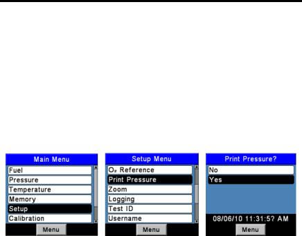
4.10. Print Pressure Selection
Select whether to print or not print the pressure measurement on the combustion test printout as follows.
1.Display the MAIN MENU by pressing the MENU (F2) button. If necessary, press ESC until MENU appears above F2.
2.Use the ▲▼ buttons to highlight SETUP, and then press ENT to display the SETUP MENU.
3.Use the ▲▼ buttons to highlight PRINT PRESSURE, and then press
ENT to display the PRINT PRESSURE screen.
4.Use the ▲▼ buttons to highlight either No (do not print pressure) or Yes
(print pressure). In the example shown, Yes has been selected.
5.Press ENT to save the selection and re-display the SETUP MENU.
Figure 4-9. Print Pressure Selection
4.11. Zoom Display Selection
Combustion test data in the Run/Hold screen can be shown with enlarged characters to make viewing easier. The operator can set zoom levels to Standard, 2X, or 3X. The Standard zoom setting will display seven lines of combustion test data at one time, 2X which will display five lines of combustion test data with enlarged characters, and 3X which will display four lines of combustion test data with enlarged characters. The operator can scroll through the complete list of measured and calculated data no matter what zoom level has been selected. Select desired zoom level as follows:
1.Display the MAIN MENU by pressing the MENU (F2) button. If necessary, press ESC until MENU appears above F2.
2.Use the ▲▼ buttons to highlight SETUP, and then press ENT to display the SETUP MENU.
3.Use the ▲▼ buttons to highlight ZOOM, and then press ENT to display the ZOOM screen.
4.Use the ▲▼ buttons to select the desired Zoom level. Options include
STANDARD, 2X, and 3X. Standard will display seven lines of Combustion test data, 2X will display five, and 3X will display four.
5.Press ENT to save the selection and re-display the SETUP MENU.
30 |
0024-9472 Rev 2 |
 Loading...