


Portable Combustion Analyzer
Instruction 24-9448
Operation & Maintenance
Rev. 4 - July 2009
Product Leadership • Training • Service • Reliability
WARRANTY
Bacharach, Inc. warrants to Buyer that at the time of delivery this Product will be free from defects in material and manufacture and will conform substantially to Bacharach Inc.’s applicable specifications. Bacharach’s liability and Buyer’s remedy under this warranty are limited to the repair or replacement, at Bacharach’s option, of this Product or parts thereof returned to Seller at the factory of manufacture and shown to Bacharach Inc.’s reasonable satisfaction to have been defective; provided that written notice of the defect shall have been given by Buyer to Bacharach Inc. within two (2) years after the date of delivery of this Product by Bacharach, Inc. The Oxygen (O2) sensor has a limited warranty of one (1) year. Routine service and calibration are excluded from this warranty.
Bacharach, Inc. warrants to Buyer that it will convey good title to this Product. Bacharach’s liability and Buyer’s remedy under this warranty of title are limited to the removal of any title defects or, at the election of Bacharach, to the replacement of this Product or parts thereof that are defective in title.
THE FOREGOING WARRANTIES ARE EXCLUSIVE AND ARE GIVEN AND ACCEPTED IN LIEU OF (I) ANY AND ALL OTHER WARRANTIES, EXPRESS OR IMPLIED, INCLUDING WITHOUT LIMITATION THE IMPLIED WARRANTIES OF MERCHANTABILITY AND FITNESS FOR A PARTICULAR PURPOSE: AND (II) ANY OBLIGATION, LIABILITY, RIGHT, CLAIM OR REMEDY IN CONTRACT OR TORT, WHETHER OR NOT ARISING FROM BACHRACH’S NEGLIGENCE, ACTUAL OR IMPLIED. The remedies of the Buyer shall be limited to those provided herein to the exclusion of any and all other remedies including, without limitation incidental or consequential damages. No agreement varying or extending the foregoing warranties, remedies or this limitation will be binding upon Bacharach, Inc. unless in writing, signed by a duly authorized officer of Bacharach.
Register Your Warranty by Visiting
www.bacharach-inc.com
Notice:
Product improvements and enhancements are continuous, therefore the specifications and information contained in this document may change without notice.
Bacharach, Inc. shall not be liable for errors contained herein or for incidental or consequential damages in connection with the furnishing, performance, or use of this material.
No part of this document may be photocopied, reproduced, or translated to another language without the prior written consent of Bacharach, Inc.
Copyright © 2006, Bacharach, Inc., all rights reserved.
BACHARACH is a registered trademark of Bacharach, Inc. All other trademarks,
trade names, service marks and logos referenced herein belong to their respective companies.
A |
Instruction 24-9448 |

Contents
Contents
1 Introduction.. . . . . . . . . . . . . . . . . . . . . . . . . . . . . . . . . . |
. |
1-1 |
||
1.1 |
PCA 2 General Description. . . . . . . . . . . . . . . |
1-1 |
||
1.2 |
Sales Combo & Model Configurations. . . . . . . . . . . |
|
.1-2 |
|
1.3 |
Features & Benefits . . . . . . . . . . . . . . . . . . |
. |
.1-4 |
|
1.4 |
Operational Overview. . . . . . . . . . . . . . . . . |
1-5 |
||
1.5 |
Connector Descriptions. . . . . . . . . . . . . . . . . .1-6 |
|||
|
1.5.1 |
Probe Connections (Gas, Pressure, T-Stack). . . . . . |
. |
.1-6 |
|
1.5.2 |
T-AIR (Primary Air Thermocouple). . . . . . . . . |
1-6 |
|
|
1.5.3 |
POWER (AC Adapter) . . . . . . . . . . . . . . |
. |
1-8 |
|
1.5.4 |
∆P (Differential Pressure). . . . . . . . . . . . . |
|
.1-8 |
|
1.5.5 |
USB (Computer Interface). . . . . . . . . . . . . |
|
.1-8 |
|
1.5.6 |
IrDA (Printer Interface). . . . . . . . . . . . . . |
. |
.1-8 |
1.6 |
1.5.7 |
OPT (Option). . . . . . . . . . . . . . . . . . |
1-9 |
|
Front Panel Buttons . . . . . . . . . . . . . . . . . . |
|
.1-9 |
||
2 Specifications. . . . . . . . . . . . . . . . . . . . . . . . . . . . . . . . . 2-1
3 Initial Setup.. . . . . . . . . . . . . . . . . . . . . . . . . . . . . . . . . . 3-1
3.1Scope . . . . . . . . . . . . . . . . . . . . . . . . .3-1
3.2Power. . . . . . . . . . . . . . . . . . . . . . . . .3-1
3.2.1Installing or Replacing Batteries. . . . . . . . . . . 3-1
3.2.2Using the AC Power Adapter. . . . . . . . . . . . .3-2
3.3Connecting the Probe and Hose Assembly. . . . . . . . . . 3-2
3.4Operating Parameters. . . . . . . . . . . . . . . . . . 3-4
3.5Fuel Selection . . . . . . . . . . . . . . . . . . . . . 3-4
3.6Temperature Units Selection . . . . . . . . . . . . . . . 3-5
3.7Pressure Units Selection. . . . . . . . . . . . . . . . . 3-6
3.8Pollution Units Selection. . . . . . . . . . . . . . . . . 3-7
3.9Date Setup. . . . . . . . . . . . . . . . . . . . . . 3-8
3.10Time Setup. . . . . . . . . . . . . . . . . . . . . . 3-9
3.11O2 Reference Setup. . . . . . . . . . . . . . . . . . 3-10
3.12Print Pressure Selection. . . . . . . . . . . . . . . . 3-11
3.13Zoom-Display Selection. . . . . . . . . . . . . . . . .3-12
3.14Battery Charger Selection. . . . . . . . . . . . . . . .3-13
3.15Logging Selection . . . . . . . . . . . . . . . . . . .3-14
3.16Button Sound. . . . . . . . . . . . . . . . . . . . .3-14
3.17Test ID Information. . . . . . . . . . . . . . . . . . . . . . . . . . . . . . . . . . .3-15
3.18Username. . . . . . . . . . . . . . . . . . . . . . . . . . . . . . . . . . . . . . . . . . .3-17
3.19Language. . . . . . . . . . . . . . . . . . . . . . . . . . . . . . . . . . . . . . . . . . . 3-19
3.20Cal Reminder Period. . . . . . . . . . . . . . . . . . . . . . . . . . . . . . . . . .3-20
3.21Run/Hold Screen Format . . . . . . . . . . . . . . . .3-21
Instruction 24-9448 |
|

Contents
4 Operation.. . . . . . . . . . . . . . . . . . . . . . . . . . . . . . . . . . . . |
4-1 |
|
4.1 |
Operating Tips. . . . . . . . . . . . . . . . . . . . |
. 4-1 |
4.2 |
Turning ON the Analyzer and Warm Up . . . . . . . . . |
. 4-2 |
4.3 |
Selecting a Fuel. . . . . . . . . . . . . . . . . . . . |
4-3 |
4.4 |
Sampling Point . . . . . . . . . . . . . . . . . . . . |
4-4 |
4.5 |
Performing a Combustion Test. . . . . . . . . . . . . . |
4-5 |
4.6Pressure Label Selection. . . . . . . . . . . . . . . . . 4-7
4.7Temperature Measurement Label . . . . . . . . . . . . . 4-8
4.8Making a Draft / Pressure Measurement . . . . . . . . . . 4-9
4.9Saving Test Data. . . . . . . . . . . . . . . . . . . .4-10
4.10Ending a Combustion Test . . . . . . . . . . . . . . . 4-11
4.11Emptying the Water Trap. . . . . . . . . . . . . . . .4-11
4.12Turning OFF the Analyzer & Purging . . . . . . . . . . 4-12
4.13Low Battery Alarm. . . . . . . . . . . . . . . . . . 4-12
4.14Data Logging. . . . . . . . . . . . . . . . . . . . .4-13
4.14.1Turning ON Data Logging. . . . . . . . . . . . .4-14
4.14.2Setting the Logging Interval and Duration. . . . . . 4-15
4.14.3Starting the Data Logging Process. . . . . . . . . 4-16
4.14.4Ending the Data Logging Process. . . . . . . . . .4-17
4.15Memory . . . . . . . . . . . . . . . . . . . . . . .4-17
4.15.1Recalling Combustion Test Data. . . . . . . . . . 4-18
4.15.2Recalling Logged Test Data. . . . . . . . . . . . 4-19
4.15.3Clearing Memory . . . . . . . . . . . . . . . . 4-20
4.16Downloading Stored Data to a Computer. . . . . . . . . .4-21
4.16.1PCA 2 Data Recovery Program Installation. . . . . 4-22
4.16.2Computer to PCA 2 Connection & USB Device
Driver Installation. . . . . . . . . . . . . . . 4-24
4.16.3Recovering Data. . . . . . . . . . . . . . . . 4-26
4.17Importing Saved Data Into a Spreadsheet. . . . . . . . . .4-29
4.18Printing Test Data. . . . . . . . . . . . . . . . . . .4-31
5 Calibration.. . . . . . . . . . . . . . . . . . . . . . . . . . . . . . . . . . . |
. |
5-1 |
|
5.1 |
Smart Sensors. . . . . . . . . . . . . . . . . . . . |
5-1 |
|
5.2 |
Starting a Calibration. . . . . . . . . . . . . . . . . |
. |
5-1 |
5.3 |
Pressure Sensor Calibration. . . . . . . . . . . . . . . |
. |
5-2 |
5.4 |
T-Stack Calibration. . . . . . . . . . . . . . . . . . |
5-4 |
|
5.5 |
T-Air Calibration. . . . . . . . . . . . . . . . . . . |
. |
5-6 |
5.6 |
CO-LO Sensor Calibration. . . . . . . . . . . . . . . |
. |
5-8 |
5.7 |
SO2 Sensor Calibration. . . . . . . . . . . . . . . . . |
|
5-10 |
5.8NO Sensor Calibration . . . . . . . . . . . . . . . . . 5-11
5.9NO2 Sensor Calibration. . . . . . . . . . . . . . . . . 5-12
5.10CO-HI Sensor Calibration. . . . . . . . . . . . . . . .5-13
ii |
Instruction 24-9448 |

Contents
6 Maintenance. . . . . . . . . . . . . . . . . . . . . . . . . . . . . . . . . . |
|
6-1 |
||
6.1 |
PCA 2 Disassembly. . . . . . . . . . . . . . . . . . |
. |
6-2 |
|
6.2 |
Water Trap / Filter Maintenance. . . . . . . . . . . . . |
|
6-6 |
|
|
6.2.1 |
Emptying the Water Trap Chamber . . . . . . . . . |
|
6-6 |
6.3 |
6.2.2 |
Replacing the Filter Element. . . . . . . . . . . . |
. |
6-6 |
Smart Sensor Replacement. . . . . . . . . . . . . . . |
6-7 |
|||
6.4 |
Sensor Only Replacement. . . . . . . . . . . . . . . . |
|
6-8 |
|
6.5 |
Nitric Oxide Sensor Battery Replacement. . . . . . . . . |
.6-10 |
||
6.6 |
Thermocouple Replacement . . . . . . . . . . . . . . . |
|
6-11 |
|
6.7 |
Pump Replacement. . . . . . . . . . . . . . . . . . |
.6-13 |
||
6.8 |
Cleaning the Probe. . . . . . . . . . . . . . . . . . |
.6-14 |
||
7 Troubleshooting.. . . . . . . . . . . . . . . . . . . . . . . . . . . . . . |
|
7-1 |
|
7.1 |
Analyzer Repair. . . . . . . . . . . . . . . . . . . . |
. |
.7-1 |
7.2 |
Error Symbols. . . . . . . . . . . . . . . . . . . . |
7-1 |
|
7.3 |
Error Messages Displayed After Warm-Up. . . . . . . . . |
. |
.7-2 |
7.4 |
Diagnostics and Status Screens. . . . . . . . . . . . . |
7-3 |
|
8 Parts & Service.. . . . . . . . . . . . . . . . . . . . . . . . . . . . . . . |
8-1 |
|
8.1 |
Replacement Parts. . . . . . . . . . . . . . . . . . . |
.8-1 |
8.2 |
Accessories. . . . . . . . . . . . . . . . . . . . . . |
8-4 |
8.3 |
Service Centers. . . . . . . . . . . . . . . . . . . . |
8-6 |
Instruction 24-9448 |
iii |

Contents
Notes:
iv |
Instruction 24-9448 |

Introduction
1 Introduction
1.1 PCA 2 General Description
The PCA 2 is a commercial-grade hand-held combustion and emissions analyzer designed for on-demand sampling of light industrial, institutional, commercial and residential furnaces, appliances, and boilers. The basic instrument is supplied with a probe and hose assembly, instruction manual, factory calibrated smart sensors, 4 'AA' alkaline batteries, Data Download Software with USB cable and carrying case.
Because of the PCA 2’s ability to measure up to four gases simultaneously, it is the perfect tool for service technicians, inspectors and boiler contractors who need to determine combustion efficiency, excess air, stack gas O2 and CO levels, stack temperature, draft, and differential pressure. The analyzer can also directly measure and display NO, NO2 and SO2 with the installation of the appropriate sensors. Combustion efficiency calculations can be conducted for the following fuels: natural gas, oil #2, oil #4, oil #6, propane, coal, wood, kerosene, bagasse, and digester gas. A large backlit graphical display shows up to eight combustion test values simultaneously, and includes a zoom capability that provides an extra large display.
Smart sensor technology allows a new sensor to be installed in the field without having to calibrate the analyzer before use. New and innovative probe and analyzer designs allow the PCA 2 to be easily serviced, thus lowering the cost of ownership.
Advanced data storage and communication features allow the operator to store up to 500 individual combustion test records, which can later be recalled for viewing, printing, or downloading to a personal computer. In
its data logging mode, the analyzer can store an additional 500 data logged records.
An optional AC power adapter allows the analyzer to run continuously for data logging purposes.
The optional sample conditioning probe is recommended when measuring NO2 and SO2 to ensure the highest degree of measurement accuracy.
Instruction 24-9448 |
1-1 |

Introduction
1.2 Sales Combo & Model Configurations
Sales Combo |
|
24-8350 |
24-8351 |
24-8352 |
Sales Combo (Kit) |
|
24-8370 |
24-8371 |
24-8372 |
Model Type |
|
225 |
235 |
245 |
PCA2 Only Part Number |
|
24-7301 |
24-7302 |
24-7303 |
Measurements |
|
|
||
Oxygen (O2) |
|
3 |
3 |
3 |
Stack Temperature |
|
3 |
3 |
3 |
Primary / Ambient Air Temperature |
|
3 |
3 |
3 |
Carbon Monoxide Low (COLow) |
|
3 |
3 |
3 |
Pressure / Draft |
|
3 |
3 |
3 |
Carbon Monoxide High (COHigh) |
|
|
|
3 |
Nitric Oxide (NO) |
|
|
3 |
|
Nitrogen Dioxide (NO2) |
|
|
|
|
Sulfur Dioxide (SO2) |
|
|
|
|
Calculations |
|
|
|
|
Combustion Efficiency |
|
3 |
3 |
3 |
Excess Air |
|
3 |
3 |
3 |
Carbon Dioxide (CO2) |
|
3 |
3 |
3 |
NOx (NOx = NO + NO2) |
|
|
|
|
NOx referenced to %O2 |
|
|
|
|
CO referenced to %O2 |
|
3 |
3 |
3 |
NO referenced to %O2 |
|
|
3 |
|
NO2 referenced to %O2 |
|
|
|
|
SO2 referenced to %O2 |
|
|
|
|
Refer to Section 8.2 for a listing of standard and optional accessories.
1-2 |
Instruction 24-9448 |

Introduction
Sales Combo |
|
24-8353 |
24-8354 |
24-8355 |
Sales Combo (Kit) |
|
24-8373 |
24-8374 |
24-8375 |
Model Type |
|
255 |
265 |
275 |
PCA2 Only Part Number |
|
24-7304 |
24-7305 |
24-7306 |
Measurements |
|
|
||
Oxygen (O2) |
|
3 |
3 |
3 |
Stack Temperature |
|
3 |
3 |
3 |
Primary / Ambient Air Temperature |
|
3 |
3 |
3 |
Carbon Monoxide Low (COLow) |
|
3 |
3 |
3 |
Pressure / Draft |
|
3 |
3 |
3 |
Carbon Monoxide High (COHigh) |
|
|
|
|
Nitric Oxide (NO) |
|
|
3 |
3 |
Nitrogen Dioxide (NO2) |
|
|
3 |
|
Sulfur Dioxide (SO2) |
|
3 |
|
3 |
Calculations |
|
|
|
|
Combustion Efficiency |
|
3 |
3 |
3 |
Excess Air |
|
3 |
3 |
3 |
Carbon Dioxide (CO2) |
|
3 |
3 |
3 |
NOx (NOx = NO + NO2) |
|
|
3 |
|
NOx referenced to %O2 |
|
|
3 |
|
CO referenced to %O2 |
|
3 |
3 |
3 |
NO referenced to %O2 |
|
|
3 |
3 |
NO2 referenced to %O2 |
|
|
3 |
|
SO2 referenced to %O2 |
|
3 |
|
3 |
Instruction 24-9448 |
1-3 |

Introduction
1.3 Features & Benefits
•Powered by 4 ‘AA’ alkaline batteries, or NiMH rechargeable batteries. An optional AC power adapter provides continuous operation.
•Internal charging circuit allows rechargeable batteries to be charged inside the analyzer with the use of the optional AC power adapter.
•O2 and COLow measurement standard. Optional measurement of up to two additional gases: COHigh, NO, NO2, or SO2.
•With the appropriate sensors installed, the analyzer optionally displays pollution conversions for CO, NO, NO2, and SO2. Pollution conversions include ppm, #/MBTU, mg/m3, and g/GJ.
•Smart sensor technology allows pre-calibrated sensors to be installed in the field.
•Automatic zero of all sensing channels on ambient air when the analyzer is first turned ON.
•Automatic flushing of the COLow sensor with fresh air if the CO level exceeds 4,000 ppm, thus protecting the COLow sensor from high CO levels. To measure CO levels above 4,000 ppm, the analyzer automatically switches to its COHigh sensor, if installed.
•Automatic purging of the gas-sample system if the detected gas levels are abnormally high when the analyzer is turned OFF.
•Displays temperatures in either °F or °C.
•Displays pressure in either inwc, mb, Pa, or hPa.
•Backlit graphic LCD with zoom capabilities.
•Low battery alarm.
•Stores 500 individual combustion records, which can later be recalled for viewing, printing, or downloading to a personal computer. Stores an additional 500 data logged records.
•Wireless IrDA link used for printing current and stored combustion records, pressure records, sensor calibration data, and diagnostic data.
•USB connectivity for downloading stored data to a personal computer.
•Field replaceable sensors and thermocouple.
•Two year warranty on analyzer and all gas sensors except the O2 sensor which has a one (1) year warranty.
1-4 |
Instruction 24-9448 |
Introduction
•Language options including English, French, and Spanish •Custom Display Formats
•Calibration Reminders - PCA2 can be set up to remind the user that calibration is past due.
1.4 Operational Overview
The PCA 2 is powered by either its 4 internal batteries, or by an optional AC power adapter that operates from any convenient source of 100–
240 VAC, 50/60 Hz power. The type of batteries used can be either disposable alkaline or rechargeable NiMH. Note that rechargeable batteries can be charged inside the analyzer using the optional AC power adapter.
The PCA 2 is controlled by 11 front panel push buttons, while a graphical LCD is used to display all combustion and emission test data and analyzer parameters.
A probe and hose assembly, with an integral thermocouple and filter/wa- ter-trap connect to the bottom of the analyzer, thus providing the means of drawing in gas samples, and for measuring stack temperature and draft.
The PCA 2 is turned ON by pressing its red I/O button. A warm-up period of 60 seconds then begins, during which time the analyzer performs self diagnostics. At the end of the warm-up period, if no errors were detected the instrument will display the Combustion Test HOLD screen. If errors were detected, the message “ERRORS DETECTED” is displayed along with a list of the errors. These errors must be corrected before proceeding with the combustion test.
Before starting a test be sure to select the fuel being burned. The default fuel selected is Natural Gas. Note that the name of the fuel being burned is indicated at the top of the display. To change the fuel: first, press the MENU (F2) button; next, select FUEL from the menu; then use the  buttons to highlight the fuel being burned; and finally, press the green ENT button to select the highlighted fuel.
To assure correct combustion-efficiency calculations, the analyzer must know the burner’s primary-air temperature. The analyzer normally uses its internal temperature sensor for the primary-air temperature value, but this method is only acceptable if the burner is using ambient room air. If the burner is drawing in cold outside air, we recommend that the optional T- AIR thermocouple be used. This thermocouple plugs into the bottom of the
Instruction 24-9448 |
1-5 |

Introduction
analyzer and is placed in the burner’s primary-air stream.
Begin the combustion test by first inserting the analyzer’s probe tube into the stack-gas stream of the appliance under test, and then pressing the RUN/HOLD button to display the Combustion Test RUN screen. The analyzer will begin to continuously monitor the stack temperature, %O2 and emission levels in the stack gas and then display measured and calculated values on its LCD. Values are listed in Section 2 Specifications.
During a test, the COLow sensor is protected from high CO levels by being automatically flushed with fresh air when the detected CO level exceeds 4,000 ppm. The analyzer will automatically start using its optional CO- High sensor, if installed, at CO levels starting at 4,001 ppm, thus providing continuous CO readings up to 20,000 ppm.
A backlight enables a user to read the display in dimly-lit areas. Turn the backlight ON and OFF by briefly pressing the I/O button.
The analyzer is turned OFF by pressing and holding down the I/O button for at least 2 seconds. Note that there is a 5-second delay before the analyzer actually turns OFF, during which time the analyzer can be turned back ON by pressing the run/hold button. In addition, there is a gas-purge feature that keeps the analyzer’s pump running if the gas level inside the sensor chambers is abnormally high at shutdown. With the probe removed from the stack and sampling fresh air, the analyzer purges itself until the detected gas concentrations drop below predetermined levels.
1.5 Connector Descriptions
1.5.1 Probe Connections (Gas, Pressure, T-Stack)
Attach the probe and hose assembly to the analyzer by connecting its . . .
•stack-gas thermocouple to the analyzer's T-STACK connector,
•stack-gas hose to the analyzer's GAS connector,
•draft hose to the analyzer's +∆P connector.
Observe that the probe connectors are of different sizes and shapes, which prevent incorrect connection to their associated connectors on the analyzer.
1-6 |
Instruction 24-9448 |

|
|
|
Introduction |
IrDA – Wireless printer |
|
|
LCD – 160 x 160 |
communications port |
|
|
graphic display |
ENT: |
|
|
F1 / F2 / F3 – |
• Selects a highlighted |
|
|
Soft Menu Buttons, |
|
|
whose functions are |
|
menu item, or confirms the |
|
|
|
|
|
defined by labels |
|
entry of data |
|
|
|
|
|
appearing above them |
|
|
|
|
|
|
|
|
on LCD |
|
|
|
USB – Computer |
RUN / HOLD: |
|
|
communications |
|
|
connector |
|
|
|
|
|
• Starts and stops a combustion |
|
|
|
efficiency test |
|
|
|
• Pressing this button during |
|
|
Arrow Buttons: |
the 5 second turn-off period will |
|
|
– Moves cursor |
keep the analyzer turned ON |
|
|
up the display, |
|
|
|
or increments an |
ESC – Displays previous menu |
|
|
alphanumerical value |
or previously viewed screen |
|
|
– Moves cursor |
|
|
|
down the display, |
I/O – Press from between |
|
|
or decrements an |
|
|
alphanumerical value |
|
1 and 2 seconds to turn |
|
|
|
|
|
– Moves cursor left, |
|
analyzer ON and OFF |
|
|
|
|
|
|
or moves to top of |
|
|
|
menu list |
– With analyzer turned |
|
|
– Moves cursor right, |
ON, press briefly to turn |
|
|
|
|
|
or moves to bottom of |
|
backlight ON and OFF |
|
|
|
|
|
menu list |
|
|
|
|
|
T-STACK – Probe’s stack-gas |
|
|
OPT – Option external |
thermocouple connector |
|
|
measurement connector |
|
|
|
T-AIR – Primary / |
POWER – AC power adapter |
T-STACK |
T-AIR |
ambient air thermo |
|
|
couple connector |
|
connector |
|
|
|
|
|
|
|
|
|
|
GAS – Probe’s gas |
|
|
|
hose connector |
“–∆P” Reference |
|
“+∆P” Probe’s draft |
|
pressure hose fitting |
|
hose fitting |
|
|
Figure 1-1. PCA 2 Components |
Instruction 24-9448 |
1-7 |

Introduction
1.5.2 T-AIR (Primary Air Thermocouple)
If thermocouple P/N 104-1797 (10 feet long) or Utility Wand P/N 104-1799 (12 inch ridged probe with handle and 5 foot coiled cable) is to be used
to measure the burner’s primary air temperature, then connect either of these thermocouples to the analyzer’s T-AIR connector.
1.5.3 POWER (AC Adapter)
The AC power adapter P/N 24-1404 can be used as an external power supply, which will run the analyzer on a continuous basis.
When using rechargeable NiMH batteries, the AC power adapter can also be used to charge the batteries while inside the analyzer. The analyzer’s rapid-charger circuit, however, must first be turned ON per Section 3.16. The rapid charger will charge a set of depleted batteries in approximately 2 - 3 hours.
When disposable alkaline batteries are used, the analyzer’s battery charger circuit must be OFF to prevent the batteries from overheating. As a precaution, the charger circuit is automatically toggled back to its OFF state when the analyzer is turned OFF.
1.5.4 ∆P (Differential Pressure)
Draft is measured by connecting the probe’s draft hose to the +∆P fitting, while leaving the –∆P fitting open to the atmosphere.
In addition to measuring draft, the “+” and “–” ∆P fittings can also be used to measure the differential pressure between two areas by first connecting a hose P/N 24-1103 to the –∆P fitting, and then inserting the open end of this hose into the area being used as the reference pressure. The analyzer’s probe is then inserted into the area where differential pressure is to be measured. Refer to Section 4.6.
1.5.5 USB (Computer Interface)
Data that has been stored in the analyzer’s memory can be downloaded to a personal computer by connecting USB data cable P/N 104-4032 between the USB ports of the computer and analyzer. Refer to Section 4.14.2.
1.5.6 IrDA (Printer Interface)
Data that has been stored in the analyzer’s memory can be printed on a
1-8 |
Instruction 24-9448 |

Introduction
compatible IrDA wireless printer by aligning their IrDA communication ports. Refer to Section 4.16.
1.5.7 OPT (Option)
The option connector is used for optional external measurement features.
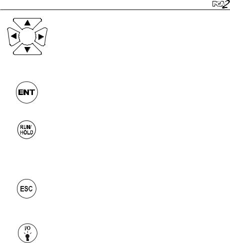
1.6 Front Panel Buttons
Descriptions of the front panel buttons are given below. Note that a control may perform multiple functions as determined by what screen is being displayed at the time.


 The functions of these buttons are defined by labels ap-
pearing above them on the LCD. The labels that appear depend on the functions that can be performed in the particular screen being displayed.
PRINT (F1): Transmits the data displayed on the screen to a printer through the IrDA communications port.
Menu (F2): Displays the Main Menu.
SAVE (F3): Saves the data currently displayed on the LCD in memory. Up to 500 individual Combustion Test and Pressure records can be saved. After 500 records have been saved, the memory must be cleared to continue saving additional data. The analyzer will not overwrite old data.
ZERO (F2): When viewing the Pressure screen, this button zeros the pressure sensor to current atmospheric conditions. When viewing the Temperature screen, this button zeroes the temperature channel difference.
PAGE– (F1): When viewing the Memory or Logging Directory, each press of this button pages down through the directory. Holding this button down speeds up the paging process.
PAGE+ (F3): When viewing the Memory or Logging Directory, each press of this button pages up through the directory. Holding this button down speeds up the paging process.
Instruction 24-9448 |
1-9 |
Introduction
The arrow buttons move the cursor on the LCD in the direction of the arrow. In screens that require the entry of alphanumerical data, use the 
 buttons to move cursor across the screen and then use the
  buttons to increment and decrement the data. When viewing a menu, use the
 buttons to quickly move to the top and bottom of the menu.
Selects a highlighted menu. In addition, if changes were made to one of the analyzer’s operating parameters (e.g., date, time, O2 reference, etc.), pressing this button confirms those changes and saves them in memory.
Starts and stops a combustion test when the Combustion Test screen is displayed. Pressing this button in any other screen returns the analyzer to the Combustion Test HOLD screen. Pressing this button during the 5 second turn-off-delay period will abort the turn-off process and also return the analyzer to the Combustion Test HOLD screen.
Displays a previously viewed screen. In addition, if changes were made to one of the analyzer’s operating parameters (e.g., date, time, O2 reference, etc.), pressing this button aborts those changes, restores the old values, and then displays the previously viewed screen.
Turns the analyzer ON and OFF, and is also used to turn the backlight and button LEDs ON and OFF.
Note that when the analyzer is turned OFF, there is a 5 second delay, during which time an operator can keep the analyzer turned ON by pressing the RUN / HOLD button. Also note that if the measured emission levels are above predetermined limits at the time the instrument is turned OFF, the pump is automatically started and purges the sensor compartment with fresh air until
the gas levels inside the analyzer are reduced. If desired, the purging process can be aborted by again pressing the I/O button.
1-10 |
Instruction 24-9448 |

Specifications
2 Specifications
The PCA 2 Directly Measures and Displays:
The gases displayed depend on the analyzer’s model number. Refer to Section 1.2.
Oxygen . . . . . . . . . . . . . . . . . . . . . . . . 0 to 20.9% Stack Temperature. . . . . . . . . . . –4 to 2,192 ºF (–20 to 1,200 ºC) Primary / Ambient Air Temperature . . . . . –4 to 999 ºF (–20 to 537 ºC) Carbon Monoxide (CO) (H2 compensated). . . . . . . . . 0 to 4,000 ppm Pressure / Draft. . . . . . . . . . . . . . . . . ±72 "H2O (±180 mb) CO High Range . . . . . . . . . . . . . . . . 4,001 to 20,000 ppm Nitric Oxide (NO). . . . . . . . . . . . . . . . . . 0 to 3,000 ppm Nitrogen Dioxide (NO2). . . . . . . . . . . . . . . . 0 to 500 ppm Sulfur Dioxide (SO2) . . . . . . . . . . . . . . . . . 0 to 5,000 ppm
The PCA 2 Calculates and Displays:
Calculations are performed only when the measured oxygen level is below 16.0%, and the stack temperature is below 2,000 °F (1,093 ºC).
Combustion Efficiency. . . . . . . . . . . . . . . . . .0.1 to 100% Excess Air. . . . . . . . . . . . . . . . . . . . . . . 1 to 250% Carbon Dioxide (dry basis). . . . . . 0.1 to fuel dependent maximum in % NOx (NOx = NO + NO2). . . . . . . . . . . . . . . . 0 to 3,500 ppm NOx referenced to %O2 . . . . . . . . . . . . . . . . 0 to 9,999 ppm CO referenced to %O2. . . . . . . . . . . . . . . . . 0 to 9,999 ppm NO reference to %O2 . . . . . . . . . . . . . . . . . 0 to 9,999 ppm NO2 reference to %O2. . . . . . . . . . . . . . . . . 0 to 9,999 ppm SO2 reference to %O2. . . . . . . . . . . . . . . . . 0 to 9,999 ppm
Fuels Available for Combustion Calculations:
•Natural Gas |
•Coal |
•Oil #2 |
•Wood |
•Oil #4 |
•Kerosene |
•Oil #6 |
•Bagasse |
•Propane |
•Digester Gas |
Instruction 24-9448 |
2-1 |

Specifications
Normal Operating Conditions:
Temperature:
Analyzer . . . . . . . . . . . . . . . . 32 to 104 ºF (0 to 40 ºC) Probe Tip. . . . . . . . . . . . . . . . . 1,472 ºF (800 ºC) Max.
Humidity:
Analyzer . . . . . . . .15 to 90% Relative Humidity, non-condensing
Air Pressure:
Analyzer . . . . . . . . . . . . . . . . . . . . . Atmospheric Probe. . . . . . . . . . . 10" H2O (25 mb) draft max. at probe tip
Performance:
Accuracy:
O2. . . . . . . . . . . . . . . ±0.3% O2 on practical concentrations of stack gas (mix of O2, CO2 and N2)
CO . . . . . . . . . . . . . . ±5% of reading or ±10 ppm, whichever is greater between 0–2,000 ppm, and ±10% of reading between 2,001–20,000 ppm.
NO. . . . . . . . . . . . . . ±5% of reading or ±5 ppm, whichever is greater between 0–2,000 ppm
NO2 . . . . . . . . . . . . . ±5% of reading or ±5 ppm, whichever is greater between 0–500 ppm
SO2 . . . . . . . . . . . . . ±5% of reading or ±10 ppm, whichever is greater between 0–2,000 ppm
Stack Gas Temp.. . . . . . . . ±4 ºF between 32 and 255 ºF (±2 ºC between 0 and 124 ºC) ±6 ºF between 256 and 480 ºF (±3 ºC between 125 and 249 ºC) ±8 ºF between 481 and 752 ºF (±4 °C between 250 and 400 °C)
Primary / Ambient Air Temp.. . . ±2 ºF between 32 and 212 ºF (±1 °C between 0 and 100 °C)
Pressure / Draft. . . . . . . . . ±2% of reading or ±0.02 "H2O (±0.05 mb), whichever is greater
System Flow Rate with Probe. . . . 200 cc/min minimum
2-2 |
Instruction 24-9448 |

Specifications
Power Requirements:
Four disposable ‘AA’ alkaline batteries provide at least 15 hours of continuous operation. NiMH rechargeable batteries can also be used, with the operating time dependent on battery type and condition.
An optional AC power adapter, which runs from any convenient source of 100–240 VAC, 50/60 Hz power, can be used to power the analyzer on a continuous basis. If using rechargeable batteries, the AC power adapter can also be used to charge the batteries while inside the analyzer.
Warm-Up Time:
60 seconds. Sensors are checked and auto zeroed during warm-up.
Memory:
•500 complete combustion test records
•500 complete logged combustion test records
Interfaces:
•Printer – Infrared (IrDA) communications
•Computer – USB
Dimensions:
9H x 3W x 2.5D inches (22.9 x 7.6 x 6.3 cm)
Weight:
•Analyzer – 1.4 lb (0.6 kg) w/ batteries
•Probe & Hose Assembly – 1 lb (0.5 kg)
Instruction 24-9448 |
2-3 |

Specifications
Notes:
2-4 |
Instruction 24-9448 |
Initial Setup
3 Initial Setup
3.1 Scope
Before using the PCA 2, you MUST:
•Install batteries, or plug in the optional AC power adapter (Section 3.2)
•Connect the probe and hose assembly (Section 3.3)
•Check, and if necessary, make changes to the analyzer’s configuration (Section 3.4)
3.2 Power
3.2.1 Installing or Replacing Batteries
Either alkaline or NiMH rechargeable batteries can used to power the analyzer. Note that if rechargeable batteries are used, they can be recharged while installed inside the analyzer using the optional AC power adapter (refer to Section 3.2.2).
Install or replace the batteries as described below:
1.Remove battery cover from back of unit (Figure 3-1.)
2.Remove (and properly dispose of) any old batteries.
3.Install a set of four ‘AA’ alkaline or NiMH batteries, per the “+” and “–” markings inside the battery compartment.
4.Replace battery cover.
Release and then remove battery cover by pushing latch up
Figure 3-1. Installing Batteries
Instruction 24-9448 |
3-1 |

Initial Setup
3.2.2 Using the AC Power Adapter
The AC power adapter is capable of powering the analyzer on a continuous basis. The adapter plugs into an appropriate 100–240 VAC, 50/60 Hz wall outlet, and produces an output of +9 VDC. The adapter’s output connector plugs into the analyzer’s POWER jack located on the bottom of the unit (Figure 3-2).
If NiMH rechargeable batteries are used, the adapter can also rapid charge these batteries in approximately 2 - 3 hours while still inside the analyzer. For the batteries to be charged, however, the analyzer’s battery charger circuit must be turned ON per Section 3.16.
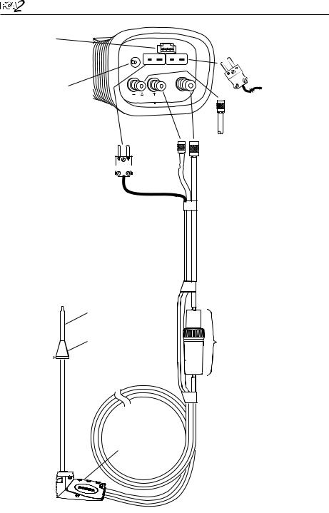
3.3 Connecting the Probe and Hose Assembly
Do the following to attach the probe and hose assembly to the analyzer (Figure 3-2):
1.Push the gas-sample hose connector, the larger of the two connectors (giving a slight twist), onto the analyzer’s GAS fitting.
2.Push the draft-hose connector, the smaller connector (giving a slight twist), onto the analyzer’s +∆P fitting.
3.Push the stack-gas thermocouple connector into the T-STACK jack (connector fits in only one way).
NOTE: The analyzer has a built-in temperature sensor for measuring ambient temperature. Perform Step 4 only if the optional primary / ambient air thermocouple is used.
4.Push the optional primary / ambient air thermocouple into the T-AIR jack (connector fits in only one way).
IMPORTANT: To assure the accurate calculation of combustion efficiency, the optional primary / ambient air thermocouple must be used when the burner’s primary-air temperature is not the same as the room temperature.
5.Inspect all hoses for cracks. If any hose is found to be defective, replace the entire probe and hose assembly. Check that the water trap is empty, and that the filter is not dirty or saturated with water.
3-2 |
Instruction 24-9448 |
Initial Setup
Option
Connector
(Optional External
Measurement)
POWER
AC Power
Adapter Jack (POWER)
Stack Gas
Thermocouple 

Connector
(T-STACK)
Probe Tube
Probe Stop
|
Primary / |
|
|
Ambient Air |
|
T-STACK T-AIR |
Thermocouple |
|
(T-AIR) (Optional) |
||
|
||
GAS |
|
|
|
Differential |
|
|
Pressure Hose |
|
|
(— ∆P) (Optional) |
|
Draft |
Gas Sample |
|
Hose |
Hose |
|
(+ ∆P) |
(GAS) |
Water Trap /
Filter Assembly
Probe
Handle
Figure 3-2. Connecting the Probe and Hose Assembly to the PCA 2
Instruction 24-9448 |
3-3 |

Initial Setup
3.4 Operating Parameters
The PCA 2 is set up at the factory for the following operating parameters:
Fuel. . . . . . . . . . . Natural Gas
Temperature Units. . . . . °F
Pressure Units. . . . . . .Inches of Water Column (inwc) Pollution Units. . . . . . .ppm
Date. . . . . . . . . . . Current MM/DD/YY
Time. . . . . . . . . . .Current EST HH:MM AM/PM O2 Reference. . . . . . . .0%
Print Pressure. . . . . . .No
Zoom. . . . . . . . . . .No
Battery Charger. . . . . . OFF
Logging. . . . . . . . . .No
Button Sound. . . . . . . ON
To change any of these parameters, perform the associated procedure provided in Sections 3.5 thru 3.22.
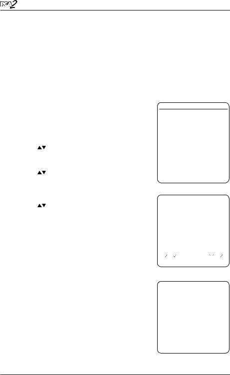
3.5 Fuel Selection
To assure the accurate calculation of combustion efficiency, select the fuel being burned as follows:
1.Display the MAIN MENU by pressing the MENU (F2) button. If necessary, press ESC until MENU appears above F2.
2.Use the  buttons to highlight FUEL, and then press ENT to display the FUEL MENU.
3.Use the  buttons to scroll through the list of available fuels until the desired fuel is highlighted. In the example shown, PROPANE has been selected. (If custom fuels are added, they will be displayed at the bottom of the list)
TIP: Use the 
 buttons to quickly scroll to the bottom and top of the list.
4.Press ENT to save the selection and display the Combustion Test HOLD screen. Observe
MAIN MENU
FUEL
PRESSURE
TEMPERATURE
MEMORY
SETUP
CALIBRATION
DIAGNOSTICS
STATUS
|
MENU |
|
F1 |
F2 |
F3 |
FUEL MENU
NATURAL GAS
OIL #2
OIL #4
OIL #6
PROPANE
COAL |
|
|
WOOD |
|
|
|
(more) |
|
|
|
|
|
MENU |
|
F1 |
F2 |
F3 |
Instruction 24-9448

Initial Setup
that the name of the selected fuel should now appear at the top of the screen.
Note: In addition to the standard fuels programmed into the PCA2, Bacharach can develop custom fuel codes based on the customers specific needs. The PCA2 can be programmed with 2 additional fuels which can be added to the instrument using the PC based software provided. Consult factory for price and delivery.
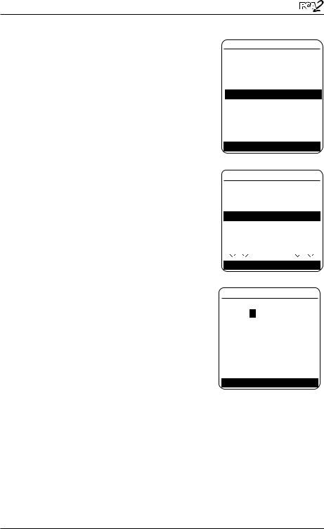
3.6 Temperature Units Selection
Select to display temperature in either °F or °C as follows:
1.Display the MAIN MENU by pressing the MENU (F2) button. If necessary, press ESC until MENU appears above F2.
2.Use the  buttons to highlight SETUP, and then press ENT to display the SETUP MENU.
3.Use the  buttons to highlight TEMP UNITS, and then press ENT to display the TEMP UNITS MENU.
4.Use the  buttons to highlight the desired temperature units. In the example shown, Fahrenheit has been selected.
5.Press ENT to save the selection and re-display the SETUP MENU.
MAIN MENU
FUEL
PRESSURE
TEMPERATURE
MEMORY
SETUP
CALIBRATION
DIAGNOSTICS
STATUS
|
MENU |
|
F1 |
F2 |
F3 |
SETUP MENU
TEMP UNITS
PRESSURE UNITS POLLUTION UNITS DATE
TIME
O2 REFERENCE PRINT PRESSURE
(more)
MENU
F1 |
F2 |
F3 |
TEMP UNITS MENU
Celsius
Fahrenheit
05/26/06 09:25:30 AM
MENU
F1 |
F2 |
F3 |
Instruction 24-9448

Initial Setup
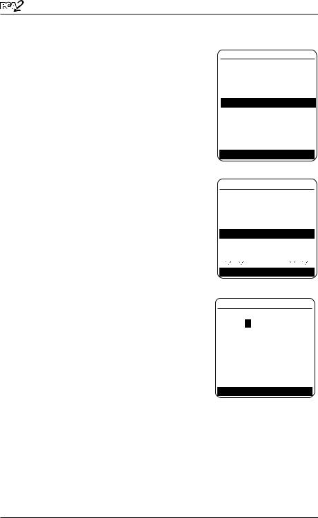
3.7 Pressure Units Selection
Select to display pressure in Inches of Water Column (inwc), millibar (mb), Pascals (Pa), or hectoPascals (hPa) as follows:
1. Display the MAIN MENU by pressing the |
FUEL |
|
|
|
||
PRESSURE |
|
|
||||
MENU (F2) button. If necessary, press ESC |
|
|
||||
TEMPERATURE |
|
|
||||
until MENU appears above F2. |
MEMORY |
|
|
|
||
|
|
|
SETUP |
|
|
|
2. Use the |
buttons to highlight SETUP, and |
CALIBRATION |
|
|
||
|
|
|
|
|
||
then press ENT to display the SETUP MENU. |
DIAGNOSTICS |
|
|
|||
|
|
|
STATUS |
|
|
|
3. Use the |
buttons to highlight PRESSURE |
|
|
|
|
|
UNITS, and then press ENT to display the |
|
|
MENU |
|
|
|
|
F1 |
F2 |
F3 |
|
||
PRESSURE UNITS MENU. |
|
|||||
|
|
|
|
|||
4. Use the |
buttons to highlight the de- |
SETUP MENU |
|
|
||
TEMP UNITS |
|
|
||||
sired pressure units. In the example shown, |
|
|
||||
PRESSURE UNITS |
|
|
||||
InchesWater has been selected. |
POLLUTION UNITS |
|
|
|||
5. Press ENT to save the selection and re-display |
DATE |
|
|
|
||
TIME |
|
|
|
|||
the SETUP MENU. |
|
|
|
|||
O2 REFERENCE |
|
|
||||
|
|
|
|
|
||
|
|
|
PRINT PRESSURE |
|
|
|
|
|
|
|
(more) |
|
|
|
|
|
|
|
|
|
|
|
|
|
MENU |
|
|
|
|
|
F1 |
F2 |
F3 |
|
|
|
|
PRESSURE UNITS MENU |
|
||
|
|
|
InchesWater |
|
|
|
|
|
|
milliBar |
|
|
|
|
|
|
Pascals |
|
|
|
|
|
|
hectoPascals |
|
|
|
|
|
|
05/26/06 09:25:30 AM |
|
||
|
|
|
|
|
|
|
|
|
|
|
MENU |
|
|
|
|
|
F1 |
F2 |
F3 |
|
Instruction 24-9448
Initial Setup
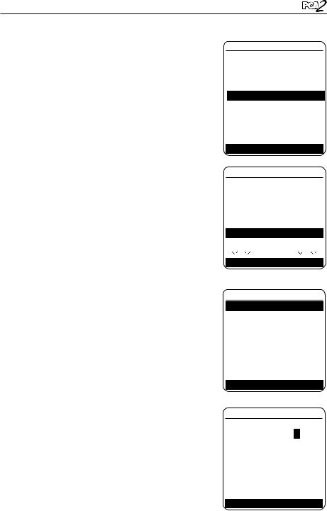
3.8 Pollution Units Selection
The PCA 2 is capable of converting the measured ppm levels of CO, NO, NO2, and SO2 to various pollution units using CFR40 Part 60 emission factors. Note that the pollution-unit conversions for NO, NO2 and NOx are based on the molecular weight of NO2.
Select to display pollution units in parts per million (ppm), pounds of pollutant per million BTU (#/Mbtu), milligrams of pollutant per cubic meter of gas (mg/m3), or grams of pollutant per gigajoule (g/GJ) as follows:
1. Display the MAIN MENU by pressing the |
FUEL |
|
|
|
||
|
|
|
|
|||
MENU (F2) button. If necessary, press ESC |
PRESSURE |
|
|
|||
TEMPERATURE |
|
|
||||
until MENU appears above F2. |
|
|
||||
MEMORY |
|
|
|
|||
|
|
|
|
|
|
|
2. Use the |
buttons to highlight SETUP, and |
SETUP |
|
|
|
|
CALIBRATION |
|
|
||||
then press ENT to display the SETUP MENU. |
DIAGNOSTICS |
|
|
|||
|
|
|
STATUS |
|
|
|
3. Use the |
buttons to highlight POLLUTION |
|
|
|
|
|
UNITS, and then press ENT to display the |
|
|
MENU |
|
|
|
|
F1 |
F2 |
F3 |
|
||
POLLUTION UNITS MENU. |
|
|||||
|
|
|
|
|||
4. Use the |
buttons to highlight the desired |
SETUP MENU |
|
|
||
TEMP UNITS |
|
|
||||
pollution units. In the example shown, ppm |
PRESSURE UNITS |
|
|
|||
has been selected. |
POLLUTION UNITS |
|
|
|||
DATE |
|
|
|
|||
|
|
|
|
|
|
|
5. Press ENT to save the selection and re-display |
TIME |
|
|
|
||
the SETUP MENU. |
O2 REFERENCE |
|
|
|||
PRINT PRESSURE |
|
|
||||
|
|
|
|
(more) |
|
|
|
|
|
|
|
|
|
|
|
|
|
MENU |
|
|
|
|
|
F1 |
F2 |
F3 |
|
|
|
|
POLLUTION UNITS MENU |
|
||
|
|
|
|
|
|
|
|
|
|
ppm |
|
|
|
|
|
|
#/Mbtu |
|
|
|
|
|
|
mg/m3 |
|
|
|
|
|
|
g/GJ |
|
|
|
|
|
|
05/26/06 09:25:30 AM |
|
||
|
|
|
|
|
|
|
|
|
|
|
MENU |
|
|
|
|
|
F1 |
F2 |
F3 |
|
Instruction 24-9448
Initial Setup
3.9 Date Setup
The date is stored in the format: MM/DD/YY. Its value is part of the date and time stamp that is saved along with each combustion test record.
Set the analyzer’s internal clock to the current date as follows:
1.Display the MAIN MENU by pressing the MENU (F2) button. If necessary, press ESC until MENU appears above F2.
2.Use the  buttons to highlight SETUP, and then press ENT to display the SETUP MENU.
3.Use the  buttons to highlight DATE, and then press ENT to display the DATE MENU.
4.First use the 
 buttons to move the cursor across the screen until it is over the digit to be changed, and then press the
  buttons until the desired value is displayed.
5.Repeat Step 4 until the values for month, day, and year have been set.
6.Press ENT to save the displayed date values and re-display the SETUP MENU, or press ESC to abort this procedure and retain the old date values.
MAIN MENU
FUEL
PRESSURE
TEMPERATURE
MEMORY
SETUP
CALIBRATION
DIAGNOSTICS
STATUS
|
MENU |
|
F1 |
F2 |
F3 |
SETUP MENU
TEMP UNITS PRESSURE UNITS POLLUTION UNITS
DATE
TIME
O2 REFERENCE PRINT PRESSURE
(more) MENU
F1 |
F2 |
F3 |
DATE MENU
DATE 05/26/06
Press ENTER to Save
05/26/06 09:25:30 AM
MENU
F1 |
F2 |
F3 |
Note: The Date and Time real time clock is powered by the main batteries and is maintained by a supercap on the Main PCB for approximately 1-2 days in the absence of batteries. The supercap is intended to maintain the real time clock when the batteries are changed when exhausted. If the batteries are removed for extended periods of time such as when the PCA2 is not in use (off-season storage), simply reset the time and date after fresh batteries are installed when it is placed back in service.
Instruction 24-9448
Initial Setup
3.10 Time Setup
The time is stored in the format: hh:mm:ss AM/ PM. Its value is part of the date and time stamp that is saved along with each combustion test record.
Set the analyzer’s internal clock to the current time as follows:
1.Display the MAIN MENU by pressing the MENU (F2) button. If necessary, press ESC until MENU appears above F2.
2.Use the  buttons to highlight SETUP, and then press ENT to display the SETUP MENU.
3.Use the  buttons to highlight TIME, and then press ENT to display the TIME MENU.
4.First use the 
 buttons to move the cursor across the screen until it is over the digit to be changed, and then press the
  buttons until the desired value is displayed.
5.Repeat Step 4 until the values for hour, minute, and meridiem have been set.
MAIN MENU
FUEL
PRESSURE
TEMPERATURE
MEMORY
SETUP
CALIBRATION
DIAGNOSTICS
STATUS
|
MENU |
|
F1 |
F2 |
F3 |
SETUP MENU
TEMP UNITS PRESSURE UNITS POLLUTION UNITS DATE
TIME
O2 REFERENCE PRINT PRESSURE
(more) MENU
F1 |
F2 |
F3 |
TIME MENU
TIME 09:25 AM
NOTE: The value for seconds cannot be en-
tered, but are displayed and stored as part of Press ENTER to Save the combustion test record.
6.Press ENT to save the displayed time values and re-display the SETUP MENU, or press ESC to abort this procedure and retain the old time values.
05/26/06 09:25:30 AM
MENU
F1 |
F2 |
F3 |
Instruction 24-9448
Initial Setup
3.11 O2 Reference Setup
The measured values of CO, NOx, and SO2 can be individually referenced to a specific O2 percentage of between 0 and 15%.
Individually set up the O2 reference value for each of the above gases as follows:
1.Display the MAIN MENU by pressing the MENU (F2) button. If necessary, press ESC until MENU appears above F2.
2.Use the  buttons to highlight SETUP, and then press ENT to display the SETUP MENU.
3.Use the  buttons to highlight O2 REF, and then press ENT to display the O2 REFERENCE screen.
4.Use the  buttons to highlight the desired measurement, and then press ENT to display the REF TO O2 screen for that measurement. In the example shown, CO has been selected.
5.First use the 
 buttons to move the cursor across the screen until it is over the digit to be changed, and then press the
  buttons until the desired value is displayed.
6.Press ENT to save the displayed value and redisplay the O2 REFERENCE screen, or press ESC to abort this procedure and retain the old O2 reference value.
7.If the O2 reference value for more than one gas is being set, then repeat Steps 4, 5, and 6 for each measurement.
MAIN MENU
FUEL
PRESSURE
TEMPERATURE
MEMORY
SETUP
CALIBRATION
DIAGNOSTICS
STATUS
|
MENU |
|
F1 |
F2 |
F3 |
SETUP MENU
TEMP UNITS
PRESSURE UNITS
POLLUTION UNITS
DATE
TIME
O2 REFERENCE PRINT PRESSURE
(more) MENU
F1 |
F2 |
F3 |
O2 REFERENCE
CO Ref to O2
NOx Ref to O2
SO2 Ref to O2
05/26/06 09:25:30 AM
|
MENU |
|
F1 |
F2 |
F3 |
SET O2 REFERENCE
CO REF TO O2: 0
05/26/06 09:25:30 AM
MENU
F1 |
F2 |
F3 |
10 |
Instruction 24-9448 |
 Loading...