


Gas Detector and Controllers
Installation and Operation Manual
Instruction 6109-9000
Revision 4 – June 2014
Product Leadership • Training • Service • Reliability

MGD-100 Manual
WARRANTY POLICY
BACHARACH, INC. WARRANTS THIS INSTRUMENT, EXCLUDING SENSORS, TO BE FREE FROM DEFECTS IN MATERIALS AND WORKMANSHIP FOR A PERIOD OF ONE YEAR FROM THE DATE OF PURCHASE BY THE ORIGINAL OWNER. THE SENSORS HAVE A WARRANTY PERIOD OF ONE YEAR FROM THE DATE OF PURCHASE. IF THE PRODUCT SHOULD BECOME DEFECTIVE WITHIN THIS WARRANTY PERIOD, WE WILL REPAIR OR REPLACE IT AT OUR DISCRETION.
THE WARRANTY STATUS MAY BE AFFECTED IF THE INSTRUMENT HAS NOT BEEN USED AND MAINTAINED PER THE INSTRUCTIONS IN THIS MANUAL OR HAS BEEN ABUSED, DAMAGED, OR MODIFIED IN ANY WAY. THIS INSTRUMENT IS ONLY TO BE USED FOR PURPOSES STATED HEREIN. THE MANUFACTURER IS NOT LIABLE FOR AUXILIARY INTERFACED EQUIPMENT OR CONSEQUENTIAL DAMAGE.
DUE TO ONGOING RESEARCH, DEVELOPMENT, AND PRODUCT TESTING, THE MANUFACTURER RESERVES THE RIGHT TO CHANGE SPECIFICATIONS WITHOUT NOTICE. THE INFORMATION CONTAINED HEREIN IS BASED ON DATA CONSIDERED ACCURATE. HOWEVER, NO WARRANTY IS EXPRESSED OR IMPLIED REGARDING THE ACCURACY OF THIS DATA.
ALL GOODS MUST BE SHIPPED TO THE MANUFACTURER BY PREPAID FREIGHT. ALL RETURNED GOODS MUST BE PRE-AUTHORIZED BY OBTAINING A RETURN MERCHANDISE AUTHORIZATION (RMA) NUMBER. CONTACT THE MANUFACTURER FOR A NUMBER AND PROCEDURES REQUIRED FOR PRODUCT TRANSPORT.
SERVICE POLICY
BACHARACH, INC. MAINTAINS AN INSTRUMENT SERVICE FACILITY AT THE FACTORY. SOME BACHARACH DISTRIBUTORS / AGENTS MAY ALSO HAVE REPAIR FACILITIES, HOWEVER, BACHARACH ASSUMES NO LIABILITY FOR SERVICE PERFORMED BY ANYONE OTHER THAN BACHARACH PERSONNEL. REPAIRS ARE WARRANTED FOR 90 DAYS AFTER DATE OF SHIPMENT (SENSORS, PUMPS, FILTERS AND BATTERIES HAVE INDIVIDUAL WARRANTIES). SHOULD YOUR INSTRUMENT REQUIRE NON-WARRANTY REPAIR, YOU MAY CONTACT THE DISTRIBUTOR FROM WHOM IT WAS PURCHASED OR YOU MAY CONTACT BACHARACH DIRECTLY.
IF BACHARACH IS TO DO THE REPAIR WORK, SEND THE INSTRUMENT, PREPAID, TO BACHARACH, INC. AT THE FOLLOWING ADDRESS.
BACHARACH, INC.
621 HUNT VALLEY CIRCLE NEW KENSINGTON, PA 15068
ATTENTION: SERVICE DEPARTMENT
ALWAYS INCLUDE YOUR RMA #, ADDRESS, TELEPHONE NUMBER, CONTACT NAME, SHIPPING/BILLING INFORMATION AND A DESCRIPTION OF THE DEFECT AS YOU PERCEIVE IT. YOU WILL BE CONTACTED WITH A COST ESTIMATE FOR EXPECTED REPAIRS PRIOR TO THE PERFORMANCE OF ANY SERVICE WORK. FOR LIABILITY REASONS, BACHARACH HAS A POLICY OF
2 |
6109-9000 Rev 4 |

MGD-100 Manual
PERFORMING ALL NEEDED REPAIRS TO RESTORE THE INSTRUMENT TO FULL OPERATING CONDITION.
PRIOR TO SHIPPING EQUIPMENT TO BACHARACH, CONTACT OUR OFFICE FOR AN RMA # (RETURNED MERCHANDISE AUTHORIZATION). ALL RETURNED GOODS MUST BE ACCOMPANIED WITH AN RMA NUMBER.
PACK THE EQUIPMENT WELL (IN ITS ORIGINAL PACKING IF POSSIBLE), AS BACHARACH CANNOT BE HELD RESPONSIBLE FOR ANY DAMAGE INCURRED DURING SHIPPING TO OUR FACILITY.
NOTICES
COPYRIGHTS: THIS MANUAL IS SUBJECT TO COPYRIGHT PROTECTION; ALL RIGHTS ARE RESERVED UNDER INTERNATIONAL AND DOMESTIC COPYRIGHT LAWS. THIS MANUAL MAY NOT BE COPIED OR TRANSLATED, IN WHOLE OR IN PART, IN ANY MANNER OR FORMAT, WITHOUT THE WRITTEN PERMISSION OF BACHARACH, INC.
ALL SOFTWARE USED AND/OR DISTRIBUTED BY BACHARACH IS SUBJECT TO COPYRIGHT PROTECTION. ALL RIGHTS ARE RESERVED. NO PARTY MAY USE OR COPY SUCH SOFTWARE IN ANY MANNER OR FORMAT, EXCEPT TO THE EXTENT THAT BACHARACH GRANTS THEM A LICENSE TO DO SO. IF THIS SOFTWARE IS BEING LOADED ONTO MORE THAN ONE COMPUTER, EXTRA SOFTWARE LICENSES MUST BE PURCHASED.
TECHNICIAN USE ONLY
THIS UNIT MUST BE INSTALLED BY A SUITABLY QUALIFIED TECHNICIAN WHO WILL INSTALL THIS UNIT IN ACCORDANCE WITH THESE INSTRUCTIONS AND THE STANDARDS IN THEIR PARTICULAR INDUSTRY/COUNTRY. OPERATORS OF THE UNIT SHOULD BE AWARE OF THE REGULATIONS AND STANDARDS IN THEIR INDUSTRY/COUNTRY FOR THE OPERATION OF THIS UNIT. THESE NOTES ARE ONLY INTENDED AS A GUIDE AND THE MANUFACTURER BEARS NO RESPONSIBILITY FOR THE INSTALLATION OR OPERATION OF THIS UNIT.
FAILURE TO INSTALL AND OPERATE THE UNIT IN ACCORDANCE WITH THESE INSTRUCTIONS AND WITH INDUSTRY GUIDELINES MAY CAUSE SERIOUS INJURY INCLUDING DEATH AND THE MANUFACTURER WILL NOT BE HELD RESPONSIBLE IN THIS REGARD.
6109-9000 Rev 4 |
3 |

MGD-100 Manual
Table of Contents
SECTION 1. |
OVERVIEW ................................................................................ |
5 |
1.1. General Information................................................................................ |
5 |
|
1.2. Technical Specifications ........................................................................ |
10 |
|
SECTION 2. |
PLACING SENSORS .................................................................. |
13 |
2.1. Installation Warnings ............................................................................ |
13 |
|
2.2. General Guidelines ................................................................................ |
13 |
|
2.3. Machinery Rooms ................................................................................. |
15 |
|
2.4. Refrigerated Spaces............................................................................... |
16 |
|
2.5. Chillers................................................................................................... |
16 |
|
2.6. Air Conditioning (Direct Systems VRF/VRV) .......................................... |
17 |
|
SECTION 3. |
HOUSING DIMENSIONS .......................................................... |
18 |
SECTION 4. |
WIRING INSTRUCTIONS .......................................................... |
23 |
4.1. Wiring MGD-100s .................................................................................. |
23 |
|
4.2. External Audible Alarm.......................................................................... |
24 |
|
4.3. DC Output.............................................................................................. |
24 |
|
4.4. Relays |
.................................................................................................... |
25 |
4.5. Power .................................................................................Connection |
25 |
|
SECTION 5. ............................................OPERATION AND STABILIZATION |
30 |
|
SECTION 6. ..................................FUNCTIONAL TESTS AND CALIBRATION |
32 |
|
6.1. Introduction .......................................................................................... |
32 |
|
6.2. Electrical ......................................................................................Reset |
34 |
|
6.3. Bump .........................................................................................Testing |
35 |
|
6.4. Calibration .............................................................................Overview |
38 |
|
6.5. Calibration ...............................................................................Options |
38 |
|
6.6. Sensor .........................................................................Board Exchange |
38 |
|
6.7. On-Site .........................................................................Gas Calibration |
39 |
|
SECTION 7. ............................................................... |
TROUBLESHOOTING |
41 |
DECLARATION ....................................................................OF CONFORMITY |
43 |
|
4 |
6109-9000 Rev 4 |

MGD-100 Manual
Section 1. Overview
1.1. General Information
The MGD-100 is the ideal gas detection solution for installations requiring a quality and affordable stand-alone gas detector. It consists of 1 to 6 remote gas sensors connected to and powered by a controller. The controller provides visual, audible, and relay alarms on the detection of gases. The system is available with one or two levels of alarm.
The MGD-100 can be used for:
•detecting refrigerant gases (including NH3 and CO2)
•speedy detection of combustible gases
•detection of toxic and VOC gases.
A range of gas detector and sensor enclosures are available for special applications.
The MGD-100 Controller is required. With the MGD-100, it creates a stand-alone gas detection system and is used to remotely monitor up to six MGD-100 devices. Models are available with 1, 2, 4, and 6 channels. Wiring diagrams are provided later in this manual.
6109-9000 Rev 4 |
5 |

MGD-100 Manual
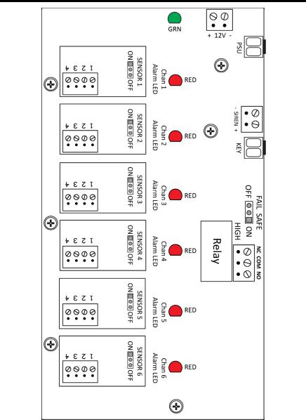
Figure 1. MGD-100 1- and 2-Channel Controller PCB
(Single Level Alarm)
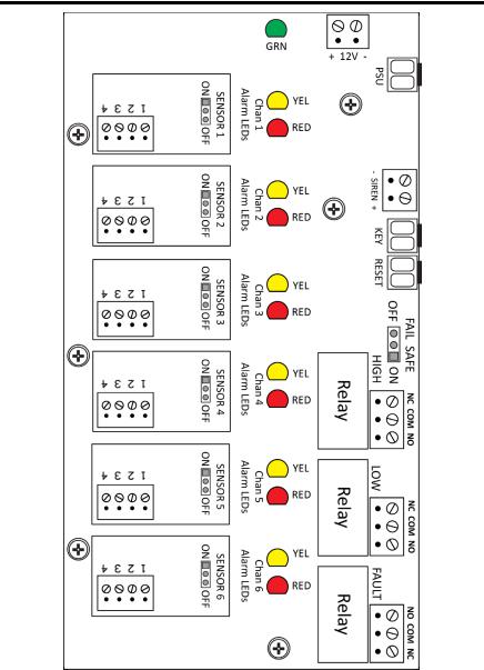
Figure 2. MGD-100 1- and 2-Channel Controller PCB
(Dual Level Alarm)
6 |
6109-9000 Rev 4 |
MGD-100 Manual
Figure 3. MGD-100 4- and 6-Channel Controller PCB
(Single Level Alarm)
6109-9000 Rev 4 |
7 |
MGD-100 Manual
Figure 4. MGD-100 4- and 6-Channel Controller PCB
(Dual Level Alarm)
8 |
6109-9000 Rev 4 |
MGD-100 Manual
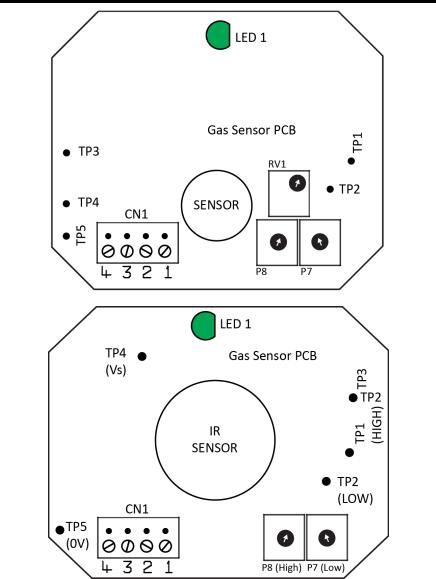
Figure 5. Examples MGD-100 PCBs
6109-9000 Rev 4 |
9 |

MGD-100 Manual
1.2. Technical Specifications
Specification |
|
|
Description |
|
|
Power Supply |
|
100 - 230 VAC 50 - 60 Hz, or 12 VDC (specified at |
|||
|
|
time of order) |
|
|
|
Alarm Silence |
|
Key Switch |
|
|
|
|
|
|
|
|
|
Alarm Delay |
|
Preset: 25 sec (low), 30 sec (high) |
|
||
|
|
|
|
|
|
Power |
|
Green |
|
|
|
Monitoring LED |
|
|
|
|
|
Alarm Relay(s) |
|
10 A, 120V/230V |
|
|
|
|
|
|
|
|
|
Warm-up Delay |
|
Minimum of 3 minutes |
|
|
|
|
|
|
|
|
|
Communications |
|
4-conductor cable (stranded); 500 ft (152 m) max; |
|||
Wiring |
|
22 AWG; Max 8.8Ω/wire |
|
|
|
|
|
|
|
|
|
Approvals |
|
UL/CSA/IEC/EN 61010-1; CE |
|
||
|
|
|
|
|
|
Sensor |
|
1- and 2-channel |
4- and 6-channel |
||
Channels |
|
systems |
systems |
||
Max Power |
|
15 W |
25 W |
||
|
|
|
|
|
|
Alarm Levels |
|
1 Level |
2 Levels |
1 Level |
2 Levels |
Audible Alarm |
|
Internal, |
Internal, |
Internal, |
Internal, |
(Buzzer) |
|
continuous |
intermittent |
continuous |
intermittent |
|
|
|
(low), |
|
(low), |
|
|
|
continuous |
|
continuous |
|
|
|
(high) |
|
(high) |
Alarm Reset |
|
Automatic |
Automatic |
Automatic |
Automatic |
|
|
|
(low |
|
(low |
|
|
|
alarm), |
|
alarm), |
|
|
|
manual |
|
manual |
|
|
|
(high |
|
(high |
|
|
|
alarm) |
|
alarm) |
Visual Alarm |
|
Red |
Yellow, |
Red |
Yellow, |
LED(s) |
|
|
Red |
|
Red |
Fault |
|
Red LED |
Red LED |
Red LED |
Red LED, |
Indication(s) |
|
|
|
|
relay |
10 |
6109-9000 Rev 4 |
|
|
|
|
|
|
|
MGD-100 Manual |
|
|
|
|
|
|
|
|
|
|
|
Specification |
|
|
|
Description |
|
||
|
|
|
1- and 2-chan systems |
|
4- and 6-chan systems |
|||
|
|
|
|
|
|
|
|
|
|
Std. Enclosure |
|
MGD: IP41 |
|
|
MGD: IP41 |
||
|
Ratings |
|
Controller: IP51 |
|
Controller: IP51 |
|||
|
|
|
|
|
|
|
|
|
|
Dimensions |
|
8.4” x 4.1” x 3.15” |
|
10.3” x 10.4” x 303” |
|||
|
and Weight: |
|
214 x 105 x 80 mm |
|
262 x 265 x 84 mm |
|||
|
Controller |
|
2.2 lbs / 1.0 kg |
|
5.1 lbs / 2.3 kg |
|||
|
|
|
|
|||||
|
|
|
|
|
|
|
|
|
|
Sensor |
|
Type/Enclosure |
|
|
Dimensions |
Weights |
|
|
Dimensions |
|
|
|
|
|
|
|
|
|
|
|
3.35” x 5.59” x 2.09” |
6.3 oz |
|||
|
and Weights |
|
IP41 |
|
||||
|
|
|
86 x 142 x 53 mm |
180 g |
||||
|
|
|
|
|
||||
|
|
|
|
|
|
|
||
|
|
|
IP66 |
|
6.89” x 6.5” x 3.29” |
1 lb 6 oz |
||
|
|
|
|
175 x 165 x 82 mm |
629 g |
|||
|
|
|
|
|
||||
|
|
|
|
|
|
|
||
|
|
|
IP66 w/ Splash |
|
6.89” x 8.9” x 3.29” |
1 lb 9 oz |
||
|
|
|
Guard |
|
175 x 225 x 82 mm |
700 g |
||
|
|
|
|
|
|
|
||
|
|
|
IP66 w/ Remote |
|
6.89” x 6.1” x 3.29” |
1 lb 11 |
||
|
|
|
|
175 x 155 x 82 mm |
oz |
|||
|
|
|
Sensor |
|
||||
|
|
|
|
|
|
|
790 g |
|
|
|
|
|
|
|
|
|
|
|
|
|
IP66 w/ Exd |
|
6.89” x 6.1” x 3.29” |
2 lb 10 |
||
|
|
|
|
175 x 155 x 82 mm |
oz |
|||
|
|
|
Remote Head |
|
||||
|
|
|
|
|
|
|
1185 g |
|
|
|
|
|
|
|
|
|
|
|
|
|
|
|
|
|
||
|
|
|
IP66 w/ PRV |
|
6.89” x 6.1” x 3.29” |
2 lb 0.3 |
||
|
|
|
|
175 x 155 x 82 mm |
oz |
|||
|
|
|
Sensor Head |
|
||||
|
|
|
|
|
|
|
916 g |
|
|
|
|
|
|
|
|
|
|
|
|
|
|
|
|
|
||
|
|
|
IP66 Airflow/ |
|
6.89” x 4.9” x 3.29” |
1 lb 4 oz |
||
|
|
|
Duct (See Table) |
|
175 x 125 x 82 mm |
578 g |
||
|
|
|
|
|
|
|
||
|
|
|
Exd (ATEX only) |
|
5.12” x 6.3” x 3.54” |
9 lb 4 oz |
||
|
|
|
|
130 x 160 x 90 mm |
4200 g |
|||
|
|
|
|
|
||||
|
|
|
|
|
|
|
|
|
|
|
|
|
|
|
|
|
|
NOTE: The hazardous area Exd Gas Monitor products are designed with individually certified Exd main housing enclosures and certified Exd remote or attached sensor enclosures. The main housing enclosure and its PCB assembly are also Exd certified, but the final Exd Gas Monitor assemblies (main enclosure and/or sensor assembly) are not currently Exd certified, but are pending additional testing.
6109-9000 Rev 4 |
11 |

MGD-100 Manual
Supported CFM and Duct Sizes for the Duct Mount Housing
Units |
|
|
Duct Size |
|
|
|
|
|
|
||
|
|
|
|
|
|
Inches |
12 x 12 |
12 x 24 |
18 x 18 |
24 x 24 |
24 round |
|
|
|
|
|
|
Feet |
1 x 1 |
1 x 2 |
1.5 x 1.5 |
2 x 2 |
Pi x 1 x 1 |
|
|
|
|
|
|
Area (ft2) |
1 |
2 |
2.25 |
4 |
3.14 |
CFM |
|
Ft/min (Based on CFM and Duct Size) |
|
||
|
|
|
|
|
|
2800 |
2800 |
n/a |
n/a |
n/a |
n/a |
3000 |
3000 |
n/a |
n/a |
n/a |
n/a |
3400 |
3400 |
n/a |
n/a |
n/a |
n/a |
3800 |
3800 |
n/a |
n/a |
n/a |
n/a |
4000 |
4000 |
n/a |
n/a |
n/a |
n/a |
4400 |
4400 |
n/a |
n/a |
n/a |
n/a |
4800 |
4800 |
n/a |
n/a |
n/a |
n/a |
5000 |
5000 |
2500 |
n/a |
n/a |
n/a |
5400 |
5400 |
2700 |
n/a |
n/a |
n/a |
5800 |
5800 |
2900 |
2578 |
n/a |
n/a |
6000 |
6000 |
3000 |
2667 |
n/a |
n/a |
6400 |
6400 |
3200 |
2844 |
n/a |
n/a |
6800 |
6800 |
3400 |
3022 |
n/a |
n/a |
7000 |
7000 |
3500 |
3111 |
n/a |
n/a |
7400 |
7400 |
3700 |
3289 |
n/a |
n/a |
7800 |
7800 |
3900 |
3467 |
n/a |
n/a |
8000 |
8000 |
4000 |
3556 |
n/a |
2548 |
8400 |
8400 |
4200 |
3733 |
n/a |
2675 |
8800 |
8800 |
4400 |
3911 |
n/a |
2803 |
9000 |
9000 |
4500 |
4000 |
n/a |
2866 |
9400 |
9400 |
4700 |
4178 |
n/a |
2994 |
9800 |
9800 |
4900 |
4356 |
n/a |
3121 |
10000 |
10000 |
5000 |
4444 |
2500 |
3185 |
12 |
6109-9000 Rev 4 |
MGD-100 Manual
Section 2. Placing Sensors
2.1. Installation Warnings
NOTE: This instrument can be equipped with a semiconductor sensor for the detection of refrigerant, combustible and VOC gases. Semiconductor sensors are not gas specific and respond to a variety of other gases including propane exhaust, cleaners, and solvents. Changes in temperature and humidity may also affect the sensor’s performance.
WARNING: Explosion hazard! Do not mount the MGD-100 in an area that may contain flammable liquids, vapors, or aerosols. Operation of any electrical equipment in such an environment constitutes a safety hazard.
CAUTION: The MGD-100 contains sensitive electronic components that can be easily damaged. Do not touch nor disturb any of these components.
NOTE: The mounting location of the monitor should allow it to be easily accessible for visual monitoring and servicing.
NOTE: The monitor must be connected by a marked, suitably located and easily reached switch or circuit-breaker as means of disconnection.
NOTE: Connect monitor power and signaling terminals using wiring that complies with local electrical codes or regulations for the intended application.
2.2. General Guidelines
NOTE: The MGD-100 should be installed plumb and level and securely fastened to a rigid mounting surface.
The MGD-100 controller and its sensor(s) should be positioned carefully to avoid mechanical damage (from moving machinery, doors, etc.) and thermal extremes (close to heaters). Units should not be placed unprotected in direct strong drafts/airflows and areas where water or moisture is present unless an appropriate enclosure is used.
6109-9000 Rev 4 |
13 |

MGD-100 Manual
Avoid routing sensor cabling outside of premises, or between buildings via overhead cables. Also, sensor wiring should be kept to a minimum of 20 in (500mm) from the main power supply and telephone cables.
When connecting the main power supply and/or sensor cables ensure a second mechanical fixing is used. Use a cable tie inside the enclosure within 1 in (25mm) of the cable termination.
When power to the unit is switched on, there is a 3-minute delay before the system activates. This allows the sensors to warm up to the correct temperature for gas detection. On a two-alarm unit, the green light on the alarm panel comes on after the delay, indicating that the system is ready. On a one-alarm system the green light comes on immediately. When a unit has been off or stored for a long time the stabilizing period may be longer than 3 minutes. After the 3 minutes has expired, alarms may activate. You may deactivate the siren until stabilization is complete. (Use the key switch on two-alarm units. Remove jumper JP1 in the case of a one-alarm unit).
Mount the controller using the mounting holes in the base such that the sensor cable terminal blocks are at the bottom of the unit in a convenient position.
Sensors must be located within the appropriate wire lengths from the controller.
In all cases the sensor supplied is designed for maximum sensitivity to a particular gas. However, in certain circumstances false alarms may be caused by the occasional presence of sufficiently high concentrations of other gaseous impurities. Examples of situations where such abnormalities may arise include the following:
•Plant room maintenance activity involving solvent or paint fumes or refrigerant leaks.
•Accidental gas migration in fruit ripening/storage facilities (bananas - ethylene, apples - carbon dioxide).
•Heavy localized exhaust fumes (carbon monoxide, dioxide, propane) from engine-driven forklifts in confined spaces or close to sensors.
A sensor response delay is built in to the system to minimize the possibilities of false alarms.
14 |
6109-9000 Rev 4 |
 Loading...