

Page 1

EMERGE® MPX EXTENDER SYSTEM
Installer/User Guide
Page 2

USA Notification
WARNING: Changes or modifications to this unit not expressly approved by the party
responsible for compliance could void the user’s authority to operate the equipment.
NOTE: This equipment has been tested and found to comply with the limits for a Class B
digital device, pursuant to Part 15 of the FCC Rules. These limits are designed to provide
reasonable protection against harmful interference in a residential installation. This
equipment generates, uses and can radiate radio frequency energy and, if not installed and
used in accordance with the instructions, may cause harmful interference to radio
communications. However, there is no guarantee that interference will not occur in a
particular installation. If this equipment does cause harmful interference to radio or television
reception, which can be determined by turning the equipment off and on, the user is
encouraged to try to correct the interference by one of the following measures:
• Reorient or relocate the receiving antenna.
• Increase the separation between the equipment and receiver.
• Connect the equipment into an outlet on a circuit different from that to which the receiver
is connected.
• Consult the dealer or an experienced radio/TV technician for help.
FCC Radiation Exposure Statement: This equipment complies with FCC radiation exposure
limits set forth for an uncontrolled environment. This equipment should be installed to
provide a 20 cm separation from all persons. This transmitter must not be co-located or
operating in conjunction with any other antenna or transmitter. Operations in the 5.15-
5.25GHz band are restricted to indoor usage only.
Canadian Notification
This digital apparatus does not exceed the Class B limits for radio noise emissions from
digital apparatus set out in the Radio Interference Regulations of the Canadian Department
of Communications.
Le présent appareil numérique n’émet pas de bruits radioélectriques dépassant les limites
applicables aux appareils numériques de la classe B prescrites dans le Règlement sur le
brouillage radioélectrique édicté par le Ministère des Communications du Canada.
Safety and EMC Approvals and Markings
FCCClass B, UL, cUL, RoHS, CE, ICES-003, WEEE
Page 3

Emerge® MPX Extender
System
Installer/User Guide
Avocent, the Avocent logo, The Power of Being There and Emerge are registered
trademarks of Avocent Corporation or its affiliates in the U.S. and other countries.
All other marks are the property of their respective owners.
© 2010 Avocent Corporation. 590-974-501B
Page 4

Instructions
This symbol is intended to alert the user to the presence of important operating and
maintenance (servicing) instructions in the literature accompanying the appliance.
Dangerous Voltage
This symbol is intended to alert the user to the presence of uninsulated dangerous
voltage within the product’s enclosure that may be of sufficient magnitude to constitute
a risk of electric shock to persons.
Power On
This symbol indicates the principal on/off switch is in the on position.
Power Off
This symbol indicates the principal on/off switch is in the off position.
Protective Grounding Terminal
This symbol indicates a terminal which must be connected to earth ground prior to
making any other connections to the equipment.
Page 5

T A BL E O F C ON T E N TS
Product Overview 1
Introduction 1
Features and Benefits 1
Video 2
Audio 2
Control 2
Browser-based user interface 2
System Overview 3
Hardware Overview 4
MPX 1450/1550 transmitter 4
MPX 1450/1550 receiver 7
MPX 1450/1550 access points 8
Compatibility with Attached Devices 10
EDID compatibility 10
Video Cross Conversion 11
Installation 13
Installation Overview 13
Getting started 13
Maximizing Your Wireless Range 14
Transmitter Configuration 15
(Optional) Transmitter media LAN settings 18
Validating media LAN connectivity 21
Access point installation 22
Receiver Configuration 23
Accessing your receiver’s web interface 23
(Optional) MPX receiver control LAN (L1) settings 24
Receiver display device settings 24
(Optional) Receiver media LAN settings 26
(Optional) Configuring receiver system settings 27
Designating a specific transmitter 27
iii
Page 6

Setting explicit receiver bindings (suggested) 28
Transmitter and Receiver Placement (MPX 1550 System Only) 30
Mounting options 35
Wall mounting 35
Table mounting 36
Initiating a Media Session 37
Operation 39
Status Monitoring 39
Connection status 39
MPX status LEDs 41
System Tuning 45
Audio 45
Video 45
Transmitter/access point tuning parameters 46
Receiver tuning parameters 48
Serial Control 49
IR Control 52
Advanced Source Device Settings 57
Displaying Firmware and Hardware Versions 58
Firmware version checking 59
Upgrading MPX firmware 59
System Reboot 62
Reset to Factory Defaults 62
Appendix A: Technical Support 63
Appendix B: System Definitions 64
Appendix C: Supported ISO Country Codes 67
Appendix D: Technical Specifications 69
Appendix E: Video Troubleshooting 73
iv Emerge® MPX Extender System Installer/User Guide
Page 7

Product Overview
1
1
Introduction
The Emerge® multipoint high-definition (HD)wired/wireless extender (MPX) system provides
wireless and wired connectivity for distribution of HD video content to one or more destinations.
The MPX extender system consists of transmitters, access points and receivers that form a
managed audio/video (A/V) extender network able to deliver a synchronized stream of HD video
and audio to as many as 64 display devices. Designed for professional A/V applications, the
MPX extender system features an integrated digital video interface (DVI-I) connector that
supports direct connection to HDMI, DVI-D, DVI-A, RGB and Component source and display
devices.
NOTE: References to "extender system"in this document refer to transmitters, receivers and accesspoints
collectively.
The MPX 1550 transmitter combines Avocent’s field-proven MPX extender technology with
IEEE 802.11n MIMO-based radios to set the highest standard for wireless HD video distribution
in terms of visual acuity, transmission distance and noise immunity. The MPX 1450 transmitter
offers all the same capabilities and features of the MPX 1550 transmitter in hardwired
environments using the existing network infrastructure. All transmitter models support up to eight
receivers, and the MPX 1450 and MPX 1550 transmitters and receivers can also be expanded
using MPX access points to increase the number of displays for large-scale venues involving
multiple floors, departments or buildings such as universities, theme parks, hospitals and airports.
For ease of installation and configuration, Emerge MPX extender systems feature an on-board
web interface that also offers powerful diagnostic tools for local or remote management.
Features and Benefits
• Wired or wireless extender systems – Emerge MPX extender systems provide installation
flexibility for wireless (MPX 1550 extender system only) or wired high-definition
applications.
Page 8

• Point-to-multipoint distribution – By adding MPX 1450 and 1550 access point expansion
units, an Emerge MPX extender system can be expanded to distribute HD video and audio
to as many as 64 display devices.
• Advanced encryption standard (AES) 128 bit encryption – A/V information is encrypted
with built-in AES for secure transmission.
• Small form factor – A smaller profile allows convenient installation and saves space where
it's needed the most.
• Dynamic binding - A transmitter can be configured to only allow specific receivers to
connect to it. Likewise, a receiver can be configured to only connect to a specific
transmitter. Specification is made using unique MAC addresses.
Video
Emerge MPX 1450/1550 transmitters and receivers feature a single DVI-I media port that
supports RGB, Component, DVI-A, DVI-D and HDMI video. Additional connectors are
provided for extension of serial and infrared (IR) data.
Audio
MPX extender systems support embedded HDMI digital audio and external analog audio via
white and red RCAconnectors.
Control
MPX extender systems allow both RS-232 and infrared control of source and display devices
and IR receiver and emitter capability. They support broadcast and bi-directional IR data
transfers for session control from the point of display or for display control from the location of
the source device; mini-jack cables allow IR blasters and receivers to be optimally placed. A
serial interface allows integration with third-party control systems.
Browser-based user interface
Browser-based configuration is available for MPX transmitters, access points and receivers. The
web interface allows local or remote control and configuration of the system without special
software tools. Through the web interface, you can configure system, network, source device
and display device settings; display hardware and firmware versions, connection status and
signal strength; update firmware; reboot the system; reset to factory defaults; and change your
password.
2 Emerge® MPX Extender System Installer/User Guide
Page 9

System Overview
The following diagram illustrates a typical configuration, including a single transmitter and up
to eight receiver units, and an expanded configuration, including a single transmitter, up to
eight access points and up to eight receiver units (MPX 1550 extender system shown).
Figure 1.1: Typical and Expanded MPX Multipoint Extender System Configuration
Table 1.1: Descriptions
Number Item
1 Source Device
2 MPXTransmitter
Chapter 1: Product Overview 3
Page 10

Number Item
3 MPXReceiver
4 DisplayDevice
5 Access Point
The MPX 1450 extender system versus the MPX 1550 extender system
The MPX 1550 extender system offers a wired or wireless solution for HD video distribution. It
features a default omni antenna with a signal strength of up to 150 feet through three interior
walls or 300 feet line of sight. The MPX 1450 extender system offers all the same capabilities
and features of the MPX 1550 extender system in hardwired environments using the existing
network infrastructure. Both the MPX 1450 and MPX 1550 extender systems have a wired
maximum video bit rate of 80 Mbps and the MPX 1550 extender system has a wireless
maximum video bit rate of 50 Mbps (1-to-many) or 110 Mbps (1-to-1). All transmitter models
support up to eight receivers, and the number of displays can be expanded using MPX
1450/1550AP access point expansion units.
Hardware Overview
MPX 1450/1550 transmitter
The transmitter digitally-encodes, compresses, encrypts and sends media signals from a source
device to a group of bound receivers.
NOTE: See "System Definitions" on page 64 for a list of common components.
The front panel of the MPX 1450/1550 transmitter and receivers are identical. The MPX 1550
units are shown as examples; the MPX 1450 units have no antennas because they are wiredonly.
4 Emerge® MPX Extender System Installer/User Guide
Page 11

Figure 1.2: MPX 1550 Transmitter
Chapter 1: Product Overview 5
Page 12

Table 1.2: MPX 1550 Transmitter Descriptions
Number
Item Description
1 Unit Reset Recessed button.
2 Front Status LEDs
Five colored LEDs that communicate the current state of the device.
See MPX status LEDs on page 41 for a detailed description of LED
status indicators.
3
Infrared Transmitter
Port - IR(Tx)
Transmitssignalsfrom an IRremote controller for transmission
through the extender network. The dual IR(Tx) emitter connects to the
port via a 3.5 mm jack.
4
Infrared Receiver Port IR(Rx)
Captures signals from an IR remote controller for transmission through
the extender network. An optional IR receiver connects to the port via a
2.5 mm mini jack.
5
Power DC power input port.
6
Serial Port
RJ-45 connector for attachment of optional DB9-UNI or DB9-DUAL
adaptor. The dual adaptor splitsthe port into two RS-232 DB9 female
connectors and supports serial passthrough for control of display
devices.
7
L1 LAN Port
RJ-45, 10/100 Mbps Ethernet for web-based management of the
transmitter.
8
L2 LAN Port
RJ-45, 10/100 Mbps Ethernet for transfer of A/V media from the
transmitter to all bound receivers/accesspoints.
9
RCA Audio Provides support for unbalanced analog stereo (left and right) audio.
10
Universal A/V Port
Provides connectivity to a wide range of display devices, including
HDMI, DVI-D, DVI-A, RGB and Component.
11
Omni-directional
Antenna
(Supported on the MPX 1550 extender system only) Used to establish
the wireless linkbetween the transmitter/accesspoints and bound
receivers. Avocent offers specialized antennas for improved distance or
higher performance in certain bands. See the Avocent web site for
more information.
6 Emerge® MPX Extender System Installer/User Guide
Page 13

MPX 1450/1550 receiver
The receiver decrypts, uncompresses and converts media signals into the desired format and
outputs the signals to the connected display device. The following diagram illustrates the
receiver (the omni-directional antenna applies only to the MPX 1550 receiver).
Figure 1.3: MPX 1550 Receiver
Chapter 1: Product Overview 7
Page 14

Table 1.3: MPX 1550 Receiver Descriptions
Number
Item Description
1
Unit Reset Recessed button.
2 Front Status LEDs
Five colored LEDs that communicate the current state of the device.
See MPX status LEDs on page 41 for a detailed description of LED
status indicators.
3
Infrared Transmit Port IR(Tx)
Transmitssignalsfrom an IRremote controller for transmission
through the extender network. The dual IR(Tx) emitter connects to the
port via a 3.5 mm jack.
4
Infrared Receiver Port -
IR(Rx)
Captures signals from an IR remote controller for transmission through
the extender network. An optional IR receiver connects to the port via a
2.5 mm mini jack.
5
Power
DC power input port.
6 Rear Status LEDs
Offers a subset of front panel status LED information. Rear status LEDs
are useful when front panel status LEDs are not visible due to
orientation of a deployed receiver.
7 Serial Port
RJ-45 connector for attachment of optional DB9-UNI or DB9-DUAL
adaptor. The dual adaptor splitsthe port into two RS-232 DB9 female
connectors. Supports serialpassthrough for control of displaydevices.
8 LAN Port
RJ-45, 10/100 Ethernet that provides combined media and control LAN
functionality.
9 Universal A/V Port
A DVI-I connector that provides connectivityto a wide range of display
devices, including HDMI, DVI-D, DVI-A, RGB and Component.
10 RCA Audio Provides support for unbalanced analog stereo (left and right) audio.
11
Omni-directional
Antenna
(Supported on the MPX 1550 extender system only) Used to establish
the wireless linkbetween the transmitter/accesspoints and bound
receivers. Avocent offers specialized antennas for improved distance or
higher performance in certain bands. See the Avocent web site for
more information.
MPX 1450/1550 access points
In installations that require more than eight display devices, up to eight MPX 1450/1550AP
access point expansion units can be added. Each expansion unit can support up to eight MPX
8 Emerge® MPX Extender System Installer/User Guide
Page 15

receivers to allow up to 64 display devices attached to a single transmitter. The inbound media
interface for both MPX 1450AP and MPX 1550AP access points must be wired. While the
outbound media interface for MPX 1450AP access points must be wired, the MPX 1550AP
access points can be wired or wireless.
Figure 1.4: MPX 1550AP Access Point
Table 1.4: MPX 1550AP Access Point Descriptions
Number Item Description
1 Unit Reset Recessed button.
Chapter 1: Product Overview 9
Page 16

Number Item Description
2 Front Status LEDs
Five colored LEDs that communicate the current state of the device.
See MPX status LEDs on page 41 for a detailed description of LED
status indicators.
3 Power DC power input port.
4 Serial Port
RJ-45 connector for attachment of optional DB9-UNI or DB9-DUAL
adaptor. The dual adaptor splitsthe port into two RS-232 DB9 female
connectors. Supports serialpassthrough for control of displaydevices.
5 L1 LAN Port
RJ-45, 10/100 Mbps Ethernet for web-based management of the
transmitter.
6 L2 LAN Port
RJ-45, 10/100 Mbps Ethernet for transfer of A/V media from the
transmitter to all bound receivers/accesspoints.
7
Omni-directional
Antenna
(Supported on the MPX 1550 extender system only) Used to establish
the wireless linkbetween the transmitter/accesspoints and bound
receivers. Avocent offers specialized antennas for improved distance
or higher performance in certain bands. See the Avocent web site for
more information.
Compatibility with Attached Devices
The following sections provide guidelines regarding compatibility with source and display
devices.
EDID compatibility
Display devices communicate with source devices using Extended Display Identification Data
(EDID), a Video Electronics Standards Association (VESA) standard data format that contains
basic information about a monitor and its capabilities, including vendor information, maximum
image size, color characteristics, factory pre-set timings, frequency range limits and character
strings for the monitor name and serial number.
EDID information stored in a display device is read by the MPX receiver via the video cable
through a digital path called the Display Data Channel (DDC). The receiver forwards this
information to the transmitter across the media LAN. The transmitter passes the EDID
information to the source device, allowing Plug and Play functionality among display and
source devices.
An MPX extender sytem group has a single primary receiver, which has special responsibilities
with regard to serial, IR and video functionality. Regarding video, only the primary receiver
10 Emerge® MPX Extender System Installer/User Guide
Page 17

passes its EDID information back to the transmitter. The display device attached to the primary
receiver should be representative of the displays attached to other receivers.
The MPX transmitter is pre-configured with default EDID information, which indicates support
for a fixed set of low video resolutions at 60 Hz. Higher resolutions are added as the transmitter
learns the capabilities of the attached display devices from actively bound MPX receivers. This
active EDIDinformation is stored in non-volatile memory and is maintained by the transmitter
unless it is intentionally restored to factory default settings. The process occurs as follows:
• The active EDID string is blank.
• When a receiver binding occurs, if the receiver is not the primary and if the active EDID
string is blank, the transmitter merges the received and default EDID strings so the
resulting string represents the common features supported by both devices. This new string
is stored as the active EDID and reported to the source device.
• When the primary receiver binds with the transmitter the first time, the merge process is
repeated using the default and primary EDID settings.
• When bindings are established with subsequent receivers, no action is taken.
• If a different receiver is selected as the primary via the transmitter’s web interface, the
merge process is repeated when a new primary EDID string is received.
• If the primary display device is replaced with a different model, the receiver reports the
information to the transmitter and a merge process takes place.
NOTE: If an accesspoint is used between the primary receiver and the transmitter, the primary receiver needs to
be configured as "Primary" on the accesspoint; likewise, the access point needs to be configured as "Primary" on
the receiver.
NOTE: A blank screen may temporarily occur as EDID changes are being processed. Restart the video session for
the change to take effect.
Video Cross Conversion
MPX extender systems are able to pass both interlaced and progressive video formats, but they
do not support interlacing or deinterlacing. It is possible cross-convert a signal from one video
format to another through the extender network. For example, RGB video received by
transmitter may be converted for output to an HDMI display device by an MPX receiver. The
receiver is able output either HDMI or DVI-D signaling as long as the input and output
resolutions are consistent. The system does not provide video scaling.
Chapter 1: Product Overview 11
Page 18

12 Emerge® MPX Extender System Installer/User Guide
Page 19

Installation
2
13
Installation Overview
Complete the following steps in order to begin installation of your MPX extender system.
• Take proper precautions against antistatic discharge.
• Remove your MPX transmitter, access points (optional), antennas (MPX 1550 extender
system only), and receivers from their boxes.
• Refer to the following kit contents list to ensure that you have all the items necessary for
yourinstallation.
• Place the units on a stable working surface. To prevent radio receivers from being overdriven, allow a distance of at least three feet between adjacent units.
• For the MPX 1550 extender system, connect the antennas. Fold the antennas inward while
the extender system units are in close proximity to each other. This will prevent excessive
signal strength, which may cause data loss andchoppy video.
• Ensure that all units are turned off at this time.
Getting started
Before installing your MPX extender system, refer to the following list to ensure you have all
items that shipped with the MPX extender system.
Supplied with the MPX extender system
• MPXtransmitter, access point(s) or receiver as appropriate
• 3 omni-directional antennas (MPX 1550 extender system only)
• Adaptor for RGB video (MPX 1450/1550T transmitter only)
• Power supply and ACline cord
• Quick Installation Guide
Page 20

Maximizing Your Wireless Range
The number, thickness and location of walls, ceilings and other objects that signals pass
through affect the range of MPX extender system units. A typical wall has metal or wood studs
covered on each side by a single layer of gypsum or plaster board. Useful transmission range
varies depending on the types of materials, obstructions and background radio frequency noise
at your place of installation.
To maximize your wireless range:
1. Keep the number of walls and ceilings between the transmitter and receiver to a minimum.
2. Position a direct line between your transmitter and receiver so that the signal travels
straight through a wall or ceiling. A wall that is 1.5 feet thick (.5 meters) at a 45° angle
appears to be almost 3 feet (1 meter) thick; at a 2° angle, it looks over 42 feet (14 meters)
thick.
3. If possible, position your devices and extender system units so the signal passes through
drywall or open doorways and not other materials. Building materials such as a solid metal
doors or aluminum studs can impede the wireless signal and will have a negative effect on
the wirelessrange.
4. Keep your MPX transmitter and receivers away (at least 3 to 6 feet or 1 to 2 meters) from
electrical devices or appliances that generate RF noise.
5. Antenna extension cables result in signal loss. When possible, move the transmitter or
receiver into the desired position in lieu of using an extension cable. When cables are
necessary, use the shortest Avocent-certified cable that allows you to properly position
your antenna. Daisy-chaining of antenna extension cables is not supported. Carefully
follow the installation instructions provided with your cable kit and properly configure the
extender when using extension cables.
NOTE: Signals will not pass through concrete walls/floors or titanium coated glass.
MPX extender system units provide wireless transmission over the Unlicensed National
Information Infrastructure (UNII) and on the Industrial, Scientific and Medical (ISM) radio
bands.
MPX extender system units are able to operate over following bands:
• UNII 1: (4 channels bonded to two 40 MHz channels) 5.15-5.25 GHz
• UNII 3: (5 channels bonded to two 40 MHz channels) 5.725 to 5.825 GHz
14 Emerge® MPX Extender System Installer/User Guide
Page 21

Transmitter Configuration
NOTE: If you prefer to mount your transmitter and receivers prior to configuration, see Mounting options on page
35.
The transmitter can be configured by using an intuitive web interface, which can be accessed
via the control LAN port with a web browser. The following steps guide you through this
process.
To configure transmitter control LAN (L1) settings:
1. Connect the power supply to the transmitter. When the unit is turned on, the two green
LEDs will light up alternately and all other LEDs will turnoff.
2. Using an Ethernet crossover cable or hub, connect a browser client to the control LAN port
(labeled L1) on the rear of the transmitter.
3. The default IP address for L1 of the transmitter is 192.168.1.1 with a subnet mask of
255.255.255.0. This may be changed using the web interface via a client computer's web
browser that is configured so it can directly access the transmitter.
4. Launch a browser session to the IP address of the transmitter to invoke its web utility via
L1, the control LAN port. The Transmitter Menu will appear.
5. Leave the username blank and type the default password, Admin (case sensitive).
6. For the MPX 1550 transmitter, if the unit has not been configured, you will be prompted to
enter a country code. This code is used by the product to establish allowable settings for
wireless bands, channels and powerlimits. For more information on country codes, see
Supported ISO Country Codes on page 67.
7. If desired, select Change Password to change the system password.
a. Type the old login password.
b. Type the new login password. The length of the password must be between 0 and 31
characters and may contain any combination of letters, digits and printable characters,
but is case sensitive.
c. Type the new login password again to verify.
d. Apply the changes.
8. Click Control LAN Settings and configure as follows.
Chapter 2: Installation 15
Page 22

a. Type the IP address for L1 (control LAN) to match the network where it will be
placed. Use this address for subsequent browser connections. Type the subnet mask for
L1.
b. Type the gateway address for L1, or 0.0.0.0 if there is no gateway.
c. The LAN Speed / Duplex setting allows you to manually select 10 or 100 Mbps LAN
speed and full or half duplex operation. By default, these settings are automatically
negotiated with your switch or hub. To ensure interoperability, compatible settings
must be selected on the Ethernet switch and MPX extender system units.
9. Apply the changes.
NOTE: Do not use the following reserved IP addresses: 224.xxx.xxx.xxx to 255.xxx.xxx.xxx. Be careful not to cause
conflict with the Control LAN IP addressesof other units on the same network or with the Media LANIP addresses
configured in the Media LAN Settings page.
NOTE: Once you change the IP addressof a unit, the browser session will terminate. Your browser session must
be re-established using the new address of the unit.
To configure transmitter source device settings:
The transmitter features a DVI-I dual-link media input port that supports DVI-D, HDMI, DVIA, RGB and Component video. To detect and process a video stream, the transmitter must be
appropriately configured.
Source Device Settings are used to configure the media cable type and display information data
(EDID) settings. Advanced settings for video positioning (panning) and clock phase
adjustments are also provided.
1. Within the web interface Transmitter Menu, select Source Device Settings.
2. The Cable Type Settings drop-down menu is used to configure the transmitter for the type
of video cable used to interconnect with the source device. Use the options as follows:
• Auto: (default) Select this option when using HDMI cable, DVI-D cable, HD15 RGB
cable if the supplied Avocent RGB adaptor is used or three-wire Component video
cable if the optional Avocent Component video adaptor-cable is used (not included).
• Manual (HDMI/DVI): Select this option to override display information data (EDID)
provided by your display device to HDMI or DVI-D source devices. Depending upon
your source device, this may provide explicit control over video resolutions options
available to users of the source device.
• Manual (RGB): You must select this option when using RGB cables without the
Avocent-supplied adaptor. You may also select this option to override display
information data (EDID) provided by your display device to RGB (also referred to as
16 Emerge® MPX Extender System Installer/User Guide
Page 23

VGA) source devices. Depending upon your source device, this may provide explicit
control over video resolutions options available to users of the source device.
• Manual (Component): You must select this option when using three-wire Component
cables without the optional Avocent Component video adaptor.
3. The MPX transmitter acts like a display device attached to the video source device; as
such, it will provide capabilities information back to the source device using an EDID
string. The Video Resolution Settings drop-down menu defines the way in which the
transmitter presents itself to the source device when queried for resolution (EDID)
information. Use the various options as follows:
• Primary: (default) This setting requests the transmitter to report the subset of
resolutions that are supported both by itself and the display device attached to the
primary receiver.
• Custom: This option requests the transmitter to report a custom set of resolutions to the
source device. Depending upon your source device, this may provide explicit control
over video resolutions options available to users of the source device. Cable Type
Settings must be set to Manual (HDMI/DVI) or Manual (RGB) for this option to be
available. This option will cause a resolution table to be displayed. Select the set of
resolutions that you want the transmitter to present to the source device.
Chapter 2: Installation 17
Page 24

Figure 2.1: Transmitter Custom Resolution Settings
• None: This setting invalidates resolution management on the transmitter, which causes
some RGB source devices to treat the transmitter as a default monitor. Choose this
mode with caution as it may allow users of the source device to select a resolution or
refresh rate that is not supported by this transmitter or by a display device attached to
an MPX receiver. Cable Type Settings must be set to Manual (RGB) for this option to
be available.
(Optional)To configure transmitter system settings:
1. Within the web interface Transmitter Menu, select System Settings.
2. If you want to select a transmitter by name rather than by MAC address, you can select a
name to identify the transmitter and type it in the Device Name text box. This name will
be displayed throughout the web interface.
18 Emerge® MPX Extender System Installer/User Guide
Page 25

3. For secure web access, HTTPS access can be used to access the web interface. The HTTPS
Required setting allows you to explicitly set HTTPS as the transport protocol for access to
the web interface. If selected, you must install the certificate from the MPX transmitter onto
your browser client. HTTPS ensures encryption of all web content. If this setting is
disabled, you may obtain a secure web session with the transmitter by launching an HTTPS
session rather than an HTTP session from your browser client.
4. The Remote Console feature allows for centralized control of the MPX extender system.
Contact Avocent technical support before you enable thisfeature.
NOTE: The Remote Console feature should only be enabled on a secure network, as it potentiallycreates a
security hole.
5. Apply the changes.
(Optional) Transmitter media LAN settings
The MPX 1550 transmitter offers additional wireless Media LAN settings that you may
optimize. These involve the topology of your extender network, broadcasting ofESSID and
transmitter power attenuation. The transmitter offers explicit modes for 1-to-1 and 1-to-many
(default configuration) operation. If your deployment consists of a transmitter and a single
receiver, you may select 1-to-1 topology mode, which optimizes the radio for 1-to-1
transmission and increases the default Video Data Rate. These optimizations should result in
fewer lost data packets and increased video acuity.
To select 1-to-1 topology (MPX 1550 extender system only):
1. Within the web interface Transmitter Menu, select Media LAN Settings – Basic LAN
Settings.
2. In the Topology Configuration drop-down menu, select 1-to-1.
3. Apply the change.
Chapter 2: Installation 19
Page 26

Figure 2.2: Transmitter Basic LAN Settings
An MPX 1550 transmitter is a specialized wireless access point. It broadcasts a name (ESSID),
which enables MPX receivers to locate and bind to it. Although it is not possible to alter this
name, you may disable the broadcasting of this name if all receivers have been explicitly
configured with the MAC address of the transmitter.
NOTE: Disabling of ESSID makes the transmitter invisible to MPX receivers and other clients that are not aware of
it. New receivers cannot be bound to the transmitter while this function is disabled.
To disable ESSID broadcast:
1. In the ESSID broadcast drop-down menu, select Disabled.
2. Apply the change.
The MPX 1550 transmitter allows you to attenuate its wireless transmission power. The unit is
pre-configured for legal settings, but it is recommended to reduce the transmission power if the
transmitter and receiver are located in close proximity. This prevents over-saturation of the
receiver’s radio and reduces the radius of the transmission range, making the wireless channel
available for transmitters and receivers that might be installed in neighboring rooms.
20 Emerge® MPX Extender System Installer/User Guide
Page 27

To attenuate transmission power:
1. In the Transmit Power Attenuation drop-down menu, select the appropriate attenuation
value.
2. Apply the change.
NOTE: Selection of this setting causes the transmitter to temporarily drop active bindings.
NOTE: Each 3dB of attenuation reduces signal strength by one half. Thus, the setting for -3dB results in one-half
power. The setting for -6dB results in one-quarter power, and the setting for -9dB results in one-eighth power. For
a small conference room, -9dB setting should be adequate; for larger auditoriums, -3dB should be adequate. For
maximum distance and wall penetration, -0dB is recommended.
To configure advanced IP settings:
1. Within the web interface Transmitter Menu, select Media LAN Settings – Advanced IP
Settings.
2. You can customize the Unicast IP Settings (namely subnet addresses and masks) for the
wired or wireless outbound media LAN connections. These settings allow you to place
multiple transmitters on a single LAN or to share it with existing equipment.
NOTE: Unicast IP Settings are used by a transmitter to exchange control messages with each of its bound
receivers. T he Unicast IP Settings of a receiver must match those of the transmitter to which it binds.
3. You can customize the multicast IP address range used for A/V streaming. This setting is
set by a transmitter and is shared by all of its bound receivers. The first octet must be 239
and the last octet must be zero. You can set the middle two octets between zero and 255
inclusively.
NOTE: The Transmitter Number setting on the Basic LAN Settings tab allows multiple transmitters to operate with
the same Unicast IP Settings and Multicast IP Address Range on a wired LAN. You can set the Transmitter Number
to zero for all units if each unit has unique Unicast IP Settings and Multicast IP Address Range.
Chapter 2: Installation 21
Page 28
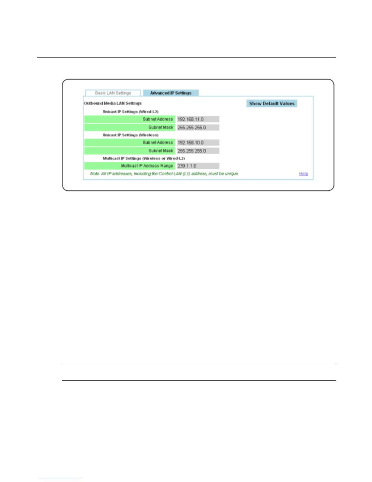
Figure 2.3: Transmitter Advanced IPSettings
Validating media LAN connectivity
Media session data (audio, video and control information) is transferred from an MPX 1450
transmitter to bound receivers through the L2 wired LAN interface. The MPX 1550 transmitter
supports both the wireless (default configuration) and wired LAN interfaces. Once the units are
turned on, MPX receivers begin to search both wired and wireless media LAN interfaces for an
accessible MPX transmitter. The following sections will guide you through a quick test of the
wireless and wired modes of operation.
(Optional) Wired media LAN (L2) setup
Perform the following steps if you wish to use MPX transmitters and receivers in a wired mode
of operation.
To set up a wired media LAN:
1. Connect the media LAN ports of the MPX transmitter and all receivers using standard 100
Mbps Ethernet hubs or switches and UTP cabling. Crossover cables may be used for pointto-point applications.
NOTE: Wired connection should be made to the L2 port of MPX transmitters and to the LAN port, indicated by the
LAN symbol, on MPX receivers.
2. Within the web interface Transmitter Menu, select Media LAN Settings.
3. Select the Selects Wired Connection radio button.
22 Emerge® MPX Extender System Installer/User Guide
Page 29

NOTE: The IP address of the MPX receiver’s media LAN port is dynamically assigned by its transmitter at bind time.
This process is similar to DHCP.
4. You may place more than one transmitter on a wired media LAN. Skip to the next step if
you are only installing one transmitter.
To install multiple transmitters, select a unique Transmitter Number from the pulldown menu on the Media LAN Settings page.
NOTE: To allow multiple groupings of transmitters and receivers to share a wired media LAN, each transmitter and
its group of receivers must have a unique set of IP addresses.The Transmitter Number setting is used to select a
unique base address for a transmitter and its associated receivers. When placing multiple transmitters on a wired
media LAN, you must budget the bandwidth available to each transmitter to avoid excessive contention. The total
video data rate across all transmitters should not exceed 60 Mbps. SeeTransmitter/access point tuning parameters
on page 46 for more information.
NOTE: Media LAN traffic is timestamped and latency sensitive by nature. For this reason, media LAN IP addresses
are not routable. A wired media LAN may be interconnected using industry-standard Ethernet cables, hubs and
switches. VLAN capable switches may also be used. Extended distance may be accomplished via fiber-based interswitch links. In all cases, the media LAN must comprise a single subnet. It is not recommended to share the media
LAN with other devices.
5. Apply the changes.
Dynamic binding
By default, the MPX transmitter accepts bind requests from eight receivers. Bound receivers are
listed on the Bindings page of the Transmitter Menu.
To validate your media LAN and bindings:
1. Plug all receiver line cords into the AC mains and turn on your receivers.
2. Wait for the LEDs on all units to bind with the transmitter. When the receivers have
successfully initialized and bound with the transmitter, the two green LEDs will cease to
alternate.
3. Within the web interface Transmitter Menu, select Bindings.
4. Scroll down to the Detected Receivers table to verify that all active receivers are listed (by
MAC address). If a receiver is not listed, verify its power state or LAN connectivity. If your
transmitter is configured for wireless operation and the receiver is not listed, you may need
to adjust the transmitter power settings. See Fine tuning suggestions on page 77 for more
information.
Access point installation
An MPX 1450/1550AP access point expansion unit acts like another receiver for the
transmitter, allowing you to transmit data to more than eight display devices.
Chapter 2: Installation 23
Page 30

To set up an MPX 1450/1550APexpansion unit:
1. Connect the power supply to the access point.
2. In the Active Receivers list, click the MAC address of the first access point to access its
web interface.
3. Apply the appropriate country code (MPX 1550 extender system only).
4. When the connection resumes, select System Settings to enter a name for the access point.
5. To configure an access point to ignore all but the currently detected transmitter, select the
detected transmitter from the Bindings page to move it into the Configured Transmitter
table. The connection will reset.
6. Repeat for each access point.
NOTE: For MPX 1450 accesspoints, the outbound Media interface must be wired. For MPX 1550 accesspoints, it
can be configured as wired or wireless. For wired outbound Media interface, it is important to ensure receivers use
the same Unicast IP Settings (Subnet Address/Mask) as the access point.
Connecting anaccess point in wired mode
By default, a receiver connects to a transmitter in wired mode. To allow a wired receiver to
connect to an access point in wired mode, configure the Inbound Unicast IP Settings on the
Media LAN Settings – Advanced IP Settings page to match the Outbound Unicast IP Settings
of the access point. For example, in factory default condition, you should set it to 192.168.12.0.
See (Optional) Receiver media LAN settings on page 26.
Receiver Configuration
Accessing your receiver’s web interface
The web interface of an MPX receiver may be accessed via the web interface of the transmitter,
or you may directly access the receiver's web interface via its LANport. To access the Receiver
Menu through the transmitter, web queries and responses are forwarded automatically between
the transmitter and receiver over the wired or wireless media LAN.
The Transmitter Menu provides web links to all actively bound receivers. Until device names
are configured, a receiver is identified by its MAC address. A similar link back to the
transmitter is provided in the web interface Receiver Menu.
NOTE: Transmitter Configuration on page 15 for detailed instructionsfor configuring the receiver password.
24 Emerge® MPX Extender System Installer/User Guide
Page 31

(Optional) MPX receiver control LAN (L1) settings
To establish a dedicated wired control LAN for management of an MPX extender system, you
must establish unique IP addresses for the control LAN ports of each receiver and transmitter to
be placed on the shared LAN.
To establish a wired control LAN for MPX receivers:
1. Interconnect the control LAN ports of the MPX receivers using industry-standard
10/100Mbps Ethernet components.
2. Connect your browser client to the control LAN.
3. Turn on a single MPX receiver and leave all other receivers with default addresses turned
off.
4. Launch a browser session to the default IP address of the MPX receiver, which is
192.168.1.2 with a subnet mask of 255.255.255.0.
5. If prompted, type the default password, Admin (case sensitive).
6. Within the Receiver Menu, select Control LAN Settings and set the parameters asfollows:
a. Enter the IP address of the control LAN to match the subnet on which it will be
placed. Use this address for subsequent browser connections. Do not use the reserved
IP address, 0.0.0.0.
NOTE: To prevent confusion between multiple receivers, it is recommended that you label each receiver with its
new IP address.
b. Enter the control LAN subnet mask.
c. Enter the control LAN gateway address, or 0.0.0.0 if there is no gateway.
7. Apply the changes.
8. Return to step 3 until all MPX receivers are configured with unique IP addresses.
Receiver display device settings
The MPX 1450/1550 receiver features a DVI-I dual-link media input port that supports DVI-D,
HDMI, DVI-A, RGBHV and Component video.
Within the Display Device Settings page in the Receiver Menu, you can configure its output
video mode and override any display information data provided by your display device with a
custom set of resolutions.
Chapter 2: Installation 25
Page 32

To configure receiver display device settings:
1. Within the Receiver Menu, select Display Device Settings, then select one of the following
options from the Cable Type and Resolution Settings drop-down menu.
a. Plug and Play: (default) This option allows the receiver to auto-detect DVI-D/HDMI
displays, RGB displays (if the video cabling and display support DDC functionality)
and Component video displays (if the optional Avocent Component adaptor-cable is
used). When MPX receivers are configured for Plug and Play, they are able to
distinguish an RGB display device from the EDID information received from the
display.
NOTE: MPX receivers cannot override EDID information received from HDMI and DVI-D display devices. To do so,
use the controls provided on Source Device Settings page in the Transmitter Menu.
b. Manual (RGB): This option requests the receiver to override EDID information, if any,
that it is able to read from the display device. You must select this option if your
display device provides invalid or no EDID information or if cabling problems or
active devices such as video splitters prevent this information from being read by the
receiver. Otherwise, the MPX receiver assumes that a display device is not present and
will not establish a video session. If this is the primary (or only) receiver, as selected
via the transmitter bindings table, this custom set of resolutions is forwarded to the
transmitter. Should you wish to take control over resolution management for any other
reason, it is best to do so via the Source Device Settings page in the Transmitter Menu.
Transmitter settings override EDID information received from all receivers. The
selected set of resolutions are passed to the MPX transmitter.
26 Emerge® MPX Extender System Installer/User Guide
Page 33

Figure 2.4: Receiver Manual Resolution Settings
c. Manual (Component): You must select this option for the receiver to output
Component video if the optional Avocent DVI to Component adaptor-cable is not
used. This setting also requests the receiver to generate EDID information on behalf of
the Component display device. If this is the primary (or only) receiver as selected via
the Bindings page in the Transmitter Menu, then this information will be forwarded to
the transmitter.
(Optional) Receiver media LAN settings
To configure advanced IP settings:
1. Within the Receiver Menu, select Media LAN Settings – Advanced IP Settings.
2. You can customize the Unicast IP Settings (namely subnet addresses and masks) for the
wired or wireless inbound media LAN connections. These settings must match those of the
transmitter to which the receiver binds.
NOTE: Unicast IP Settings are used by a receiver to exchange control messages with the transmitter to which it
binds.
Chapter 2: Installation 27
Page 34

3. By default, a receiver is set up to connect to a transmitter in wired mode, using subnet
address 192.168.11.0. To connect to an access point in default condition, you should
change the Unicast IP (Wired) Subnet Address to 192.168.12.0.
NOTE: See "Video Troubleshooting" on page 73 for information regarding the Media LAN Performance table.
Figure 2.5: Receiver Advanced IP Settings
(Optional) Configuring receiver system settings
To configure receiver system settings:
1. Within the web interface Receiver Menu, select System Settings.
2. Type a Device Name to associate a name with the unit. The device name may contain any
combination of printable characters, but cannot exceed 127 characters.
3. The Display Status Screens page allows you enable and disable the display of status
messages on the display device. Status messages include diagnostic information that may
be useful during initial installation.
4. Apply the changes.
Designating a specific transmitter
When a receiver is rebooted, it searches for an MPX transmitter and attempts to bind with the
first detected transmitter if a specific transmitter is not designated. You may wish to constrain a
receiver to a specific transmitter for the following reasons:
• If multiple transmitters are in close proximity, this allows each receiver to be tied to a
specifictransmitter.
28 Emerge® MPX Extender System Installer/User Guide
Page 35
• Designation of a specific transmitter ensures that rogue transmitters are ignored by your
receivers.
• If all receivers are tied to specific transmitter, it is possible to disable ESSID broadcast on
your transmitter. Disabling of ESSID broadcast provides yet another layer of security for
your system (MPX 1550 extender system only).
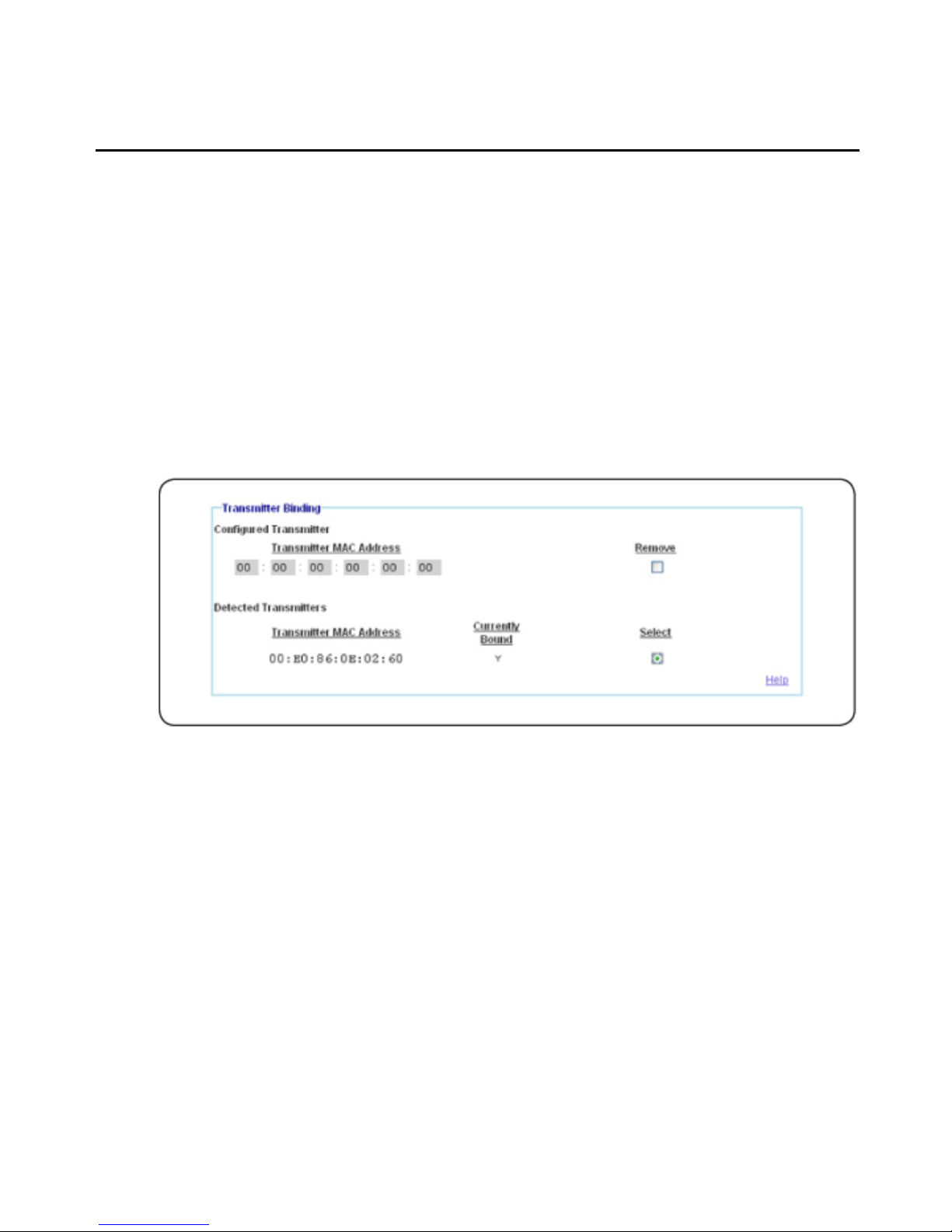
To designate a specific transmitter:
1. Within the web interface Receiver Menu, select Bindings.
2. Select the desired transmitter in the Detected Transmitters table or enter the MAC address
of the desired transmitter directly in the Configured Transmitter table.
3. Apply the changes.
Figure 2.6: Transmitter Binding Page
Setting explicit receiver bindings (suggested)
By default, a transmitter will accept bind requests from any receiver. A bound receiver
participates in media sessions with the transmitter. The explicit bindings feature allows you to
configure the transmitter to only accept bind requests from a list of specific receivers; other
requests will be rejected. Unbound receivers may be bound by a differenttransmitter.
Explicit bindings offer the followingbenefits:
• Loss of connection with dynamically bound receivers is not treated as an error
condition by the transmitter. Explicitly bound receivers will be flagged as nonresponsive if they drop connection with the transmitter.
Chapter 2: Installation 29
Page 36

• Explicit bindings allow for the selection of a primary receiver, which enables the
following functionality:
• It allows for bi-directional serial and IR communications. Without a primary, serial
and IR data is broadcast by the transmitter to all receivers and return data are
ignored. The primary receiver selection may be changed as needed throughout a
video session.
• It allows a particular display device to be established as the source for EDID
information. Without a primary receiver, EDID information is accepted from the
first receiver that connects to a transmitter, which may result in seemingly random
behavior if the various display devices offer different EDID information.
• Multi-transmitter configurations require explicit pairings of receivers to transmitters.
The Bindings page in the Transmitter Menu contains separate tables for detected receivers and
configured receivers. The Detected Receivers table lists each receiver that has requested binding
from the transmitter. Each entry provides the MAC address and bind status of the receiver. The
Configured Receivers table provides explicit controls for receiver binding. A check box is
provided to add detected receivers to the Configured Receivers table. You can also enable the
Automatically Bind Detected Receivers option to create a global setting for receiver bind
requests.
NOTE: Automatic binding results in a dynamic extender network in which receivers bind and unbind as they are
turned on and off. Although simple to establish, dynamic extender networks lacka primary receiver, which prevents
the transmission of bi-directional serialand IR data.
To establish explicit receiver bindings:
1. Before configuring explicit bindings, it is recommended that you disable the Automatically
Bind Detected Receivers option. If left enabled, the transmitter automatically binds all
detected receivers that are not explicitly disabled for binding in the Configured Receivers
table.
2. Select the Add to Configured Receivers checkbox next to each detected receiver in the
Detected Receivers table.
3. Apply the changes.
4. For each receiver associated with the transmitter, select the Bind Allowed checkbox in the
Configured Receivers table. The remaining receivers may be bound to a different
transmitter.
5. Click the Primary button to assign one unit as the primary receiver for bi-directional
exchange of IR and serial data and reception of EDID information.
6. Apply the changes.
30 Emerge® MPX Extender System Installer/User Guide
Page 37

NOTE: (Optional) You may manually enter a receiver’s MAC address. MAC address labels are affixed to the
bottom of an MPX receiver.
Figure 2.7: Bindings Page
Transmitter and Receiver Placement (MPX 1550 System Only)
To find acceptable locations for your units:
1. Turn off all transmitters, receivers, access points, source device and display devices.
2. Place the transmitters, access points and receivers in their desired locations.
3. If you have a PC-based application that is able to detect nearby access points or if you
have a handheld spectrum analyzer, use it to identify unused channels. Once identified,
turn on your MPX transmitter and configure it to use an available channel via the Media
LAN Settings page in the Transmitter Menu.
4. Turn on all remaining MPX extender system units and raise antennas to their upright
positions. Allow the units to initialize and bind.
Chapter 2: Installation 31
Page 38

5. Using the receiver signal strength indicator for guidance, position the units and antennas as
needed to obtain optimal signal strength. If possible, try to obtain three or more signal
strength LEDs on the front of the receiver and an average frame rate of 28 or greater on all
receivers.
NOTE: Radio signals propagate outward from an omni-directional antenna in a disk-like perpendicular manner. A
verticalantenna results in horizontal signal propagation. For thisreason, it is best to start with transmitter and
receiver antennas that are similarly oriented and aligned on the same horizontal or vertical plane. Vertical antennas
result in horizontal emission. High-gain antennas produce a narrowed yet stronger beam of radio waves than low
gain antennas, so it is more critical to position transmitters and receivers on the same plane when using high-gain
antennas.
NOTE: If transient obstructions, such as people, boxes or vehicles are anticipated during normal operation, then
simulate these factors as best you can to observe their effect upon signal strength under real-worldconditions.
6. If necessary, signal strength may be optimized asfollows:
a. Increase your transmitter power.
b. Use specialized directional or high-gain antennas.
c. Use antenna extension cables to raise antennas above obstructions or to pass RF
signals through concrete walls. Although extension cables allow for optimal antenna
placement, they will attenuate signal strength, so they should only be used when
necessary and kept to a minimum length. Proper placement of your receiver is
preferable to using extension cables. Never connect extension cables together as a
means of extending antenna placement. This will result in excessive signal loss.
d. Reposition your extender system units. A slight movement of several inches may result
in a noticeable increase of signalstrength.
e. Orient your antennas as needed to account for:
• Antenna polarity: RF antennas are polarized. The default MPX extender system
antenna is a dipole antenna, which emits and responds to vertically-oriented RF
signals. The Avocent UNI-8DB antenna emits and responds to horizontallyoriented RF signals. When signals pass between these two types of antennas, one
must be rotated into a 3 or 9 o’clock position.
NOTE: Failure to orient antennas for proper polarity will cause cross-polarization, which resultsin severe
attenuation of signal strength.
Elevation differences: Signal strength is optimal at the same horizontal plane as a transmitting
antenna. The signal becomes increasingly weaker both above and below this plane. As
illustrated in Figure 2.8, if a transmitter and receiver are positioned on dissimilar horizontal
levels (greater than 30 degrees above or below each other), the strongest beam of each antenna
32 Emerge® MPX Extender System Installer/User Guide
Page 39

will not intersect. In this case, signal strength may be optimized through appropriate up or
down tilt of their respective antennas, as illustrated in Figure 2.9. Notice how the primary lobe
of each beam of each antenna is tilted toward the other antenna. Tilt is accomplished by a
slight rotation of the antenna at its base or tilting of the articulating arm of the antenna in the
appropriate direction. Once properly aligned, all antennas should be parallel to each other. A
dab of radio cement or silicon gel can be used to lock the antenna arms inposition.
Figure 2.8: Vertically Misaligned Antennas
Chapter 2: Installation 33
Page 40

Figure 2.9: Vertically Aligned Antennas
• Reflections: Depending upon your environment, you may want to orient the
antennas on your transmitters and receivers so that one antenna on each unit is
upward in a 12 o’clock position and the other antenna is perpendicular to it, in a 3
or 9 o’clock position. To prevent cross-polarization, each system should have one
horizontal and one vertical antenna. The vertical antenna will radiate on a
horizontal plane and the horizontal antenna will radiate on a vertical plane. This
may increase the benefit of antenna diversity by taking advantage of diverse
reflections off of environmental objects such as walls, floors, desks andceilings.
Use this technique only if signal strength is noticeably improved.
f. Use lower frequency channels to slightly increase transmission distance and wall
penetration.
g. As a final optimization, compare receiver signal strength across all frequencies. Starting
at the lowest frequency, make note of the weakest signal strength reported by any
receiver. Select the next frequency via the Media LAN Settings page in the Transmitter
Menu. Allow the receivers to bind. Again, record the weakest signal strength reported
by any receiver. Repeat this process until all channels have been tested. Set the
transmitter for the channel that resulted in the strongest recorded signal strength. Take
34 Emerge® MPX Extender System Installer/User Guide
Page 41
care to evaluate only those channels that are compatible with the antennas that you
have selected. For example, do not test G band channels with UNII band antennas.
7. Once acceptable signal strength is attained, turn off the MPX transmitter, access points and
receivers.
8. If your antennas will be subject to wind or other forces that might cause them to rotate out
of position, consider using a few drops of silicon gel to lock the position of theantenna.
9. Attach the video and audio source devices to the MPX transmitter.
10. Attach the video display and audio devices to the MPX receiver(s) and turn them all on.
11. Turn on your MPX transmitter and access points and wait for the receivers to bind.
12. Turn on your source device.
13. Start a media stream from the source device to the MPX transmitter.
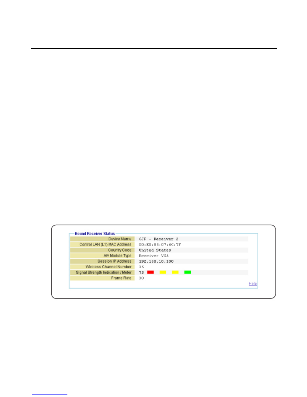
14. Click Connection Status in the Transmitter Menu. The following figure illustrates the
Bound Receiver Status table. Verify frame rate and signal strength for each of the bound
receivers. The Media LAN Performance page provides detailed performance information for
all of the attached receivers.
The output of audio and video media should now be active at each display device, as if they
were each individually attached to the source device. Inspect each display for signs of
hesitation, color shift, audio loss, or other anomalies.
Figure 2.10: Bound Receiver Status Page
If video fails to appear on your display device or if Plug and Play functionality is not
functioning normally, see Video Troubleshooting on page 73 for detailed information.
Chapter 2: Installation 35
Page 42

If you intend to use the extender network to pass serial or IR control signals, see Serial Control
on page 49 and IR Control on page 52 for more information.
Mounting options
Wall mounting
An optional keyhole style wall mounting bracket is available for MPX 1450/1550 receivers.
The bracket also provides screw slots for tablemounting.
Figure 2.11: MPX 1550 Wall Mount Bracket
NOTE: The keyhole style bracket is compatible only with MPX 1450/1550 receivers. The bracket is not compatible
with MPX 1450/1550 transmitters.
To install the mounting bracket:
1. Use the bracket as a template to mark desired holes on the mounting surface.
2. Insert mounting screws into the drilled holes.
3. Attach the bracket to the receiver using the supplied pan head machine screws.
36 Emerge® MPX Extender System Installer/User Guide
Page 43

NOTE: Take care to orient the bracket such that the narrow portion of keyhole slot will interlock with the heads of
the mounting screws when the unit suspended upon them.
4. Slots on outer edge of bracket can be used after the bracket is installed to the receiver.
Hold the receiver / bracket against the mounting surface and drive screws thru slots. Screws
along bottom edge should be installed before plugging in cables.
Table mounting
An optional L-bracket is available that allows for table mounting of MPX 1450/1550
transmitters and receivers. The kit contains two brackets and four mounting screws. Either
bracket may be used as a left- or right-hand bracket and may be oriented for table top or under
table mounting. The bracket may be used in conjunction with the power supply bracket.
Figure 2.12: MPX 1450/1550 Table Mount Bracket
To install the mounting bracket:
1. Remove the two lid retention screws from each side of the transmitter or receiver.
2. Align the bracket with the chassis screw holes. The bracket may be oriented for table top
or under table mounting.
3. Attach the bracket to unit using the supplied pan head machine screws.
4. Mount the brackets to the table top or bottom, as desired. Screws are not provided for this
purpose.
Chapter 2: Installation 37
Page 44

NOTE: After the brackets are on the unit, the four table mounting holes provide a VESA 100 mm X 200 mm pattern.
Power supply bracket
An optional power supply bracket kit is available for MPX 1450/1550 extender systems. This
bracket may be used to affix to the external power adaptor to the chassis of the MPX
1450/1550 receiver.
Figure 2.13: MPX 1450/1550 Power Supply Bracket
To install the power supply bracket:
1. Using the screws provided, attach the bracket to the side of the MPX 1450/1550 receiver
chassis. Do not attach the top screw at this time.
2. Place the power supply into the bracket.
3. Fasten the bracket to the top of the MPX 1450/1550 chassis using the provided screw.
4. Use tie wraps if needed to neatly contain excess AC and DC line cords.
Initiating a Media Session
Your MPX extender system is now ready for a media session.
38 Emerge® MPX Extender System Installer/User Guide
Page 45

The following steps allow you to verify proper operation of your transmitter, access points and
receivers, establish an Active EDID string at the MPX transmitter and test compatibility of your
source and display devices through the extender system.
To establish your first media session across the extender system:
1. Turn off all MPX transmitters, receivers, access points, source device and display devices.
2. Attach your display device to the primary MPX receiver using an appropriate cable.
NOTE: If your displaydevice does not support DDC2B or if a cable or video switching device prevents the normal
flow of EDID information acrossthe DDC bus, then the source device willnot know what resolutions are supported
by the attached primary display device. In thiscase, the allowed resolutions may need to be set up manually in the
transmitter.
3. Turn on the display device.
4. Turn on the primary MPX receiver and any access points connected to it.
NOTE: This sequence for turning on the units ensures that proper EDID information is stored in the MPX
transmitter before the source device attempts to read it. The order in which you turn on the units is only important
during initial configuration and setup. If you must replace a field-installed MPX transmitter with another unit, these
same steps should be used to properly establish valid EDID information in the new unit.
5. Attach the source device to the MPX transmitter using an appropriate cable.
6. Turn on the MPX transmitter.
7. Wait for the MPX receiver to bind with the MPX transmitter, as previously described.
8. Turn on your source device and make sure the source device is providing audio and video
content.
9. Active video should appear on the display device attached to the MPX receiver within 30
seconds of the source device initializing.
Chapter 2: Installation 39
Page 46

40 Emerge® MPX Extender System Installer/User Guide
Page 47

Operation
3
39
Status Monitoring
The web interface provides two pages for system monitoring: the Connection Status page and the
Media LAN Performance page. The Connection Status page offers a status table for the
transmitter and a separate table for each receiver.
Connection status
The Connection Status page in the Transmitter Menu displays the operational status of the
transmitter and all bound receivers. The content on this page dynamically refreshes every five
seconds. Some functions listed are specific to the transmitters or receivers. The following table
describes the status information that is provided for MPX transmitters (Tx), MPX receivers (Rx) or
both. Access points behave like transmitters in the table.
Table 3.1: Connectio n Status Page Information
Field Tx/Rx Description
Device
Name
Both
Provides a name for an MPX transmitter or receiver for ease of identification within the
web interface.
Control LAN
MAC
Address
Both
L1 MAC address(control LAN) of the transmitter or receiver, also printed on an external
label on the unit.
Wired Media
LAN MAC
Address
Tx L2 MAC address(media LAN) of the transmitter.
Serial
Number
Tx The serial number assigned to the transmitter or receiver.
Page 48

Field Tx/Rx Description
OEM ID Tx
The OEM identifier assigned to the transmitter or receiver. This information may be
required for technicalsupport but is not required for normal use of the product.
Country
Code
Both The country code for the product.
Product
Type
Both The product type for the unit; for example: MPX 1450/1550R.
Operational
Status
Both
For transmitters, this field will indicate the number of bound/active receivers. For
receivers, thisfield will indicate if the receiver is currently connected to a transmitter. For all
units, this field will provide Flash upgrade status.
Session
Transmitter
Device
Name
Rx The device name of transmitter to which this receiver is currently bound.
Wireless
Channel
Number
Both The wireless channel number in use. Only displayed on wireless extensionnetworks.
A/V Source
Type
Tx Type of source device: HDMI, DVI-D, RGB and Component.
A/V Source
Resolution
Tx
Resolution, such as 1024 x 768 @ 60 Hz, of the source device. An asteriskafter the field
name (A/V Source Resolution*) indicates that a non-standard resolution has been
detected and is currently in use.
A/V Encoder
Running
Tx An indication that video is being encoded and transmitted in real-time.
A/V Source
Error
Tx Helpful diagnosticmessages; for example: No video detected at source or similar error.
Primary
Video
Resolutions
Tx A list of all resolutions that the primary receiver has reported to the transmitter.
Video
Resolutions
in Use
Tx A list of resolutionsthat have been reported to the source device by the primary display.
RGB Video
Resolutions
Stored
Tx
Resolutions that are currently stored in the Active EDID string of the transmitter. This field
is present for RGB displaydevicesonly.
40 Emerge® MPX Extender System Installer/User Guide
Page 49

Field Tx/Rx Description
Signal
Strength
Indication
Rx
An indication of the wireless signal strength on the receiver. Onlydisplayed on wirelessA/V
networks. Ranges from 0 to 100, with 0 representing weak signal strength and 100
representing maximum signalstrength. A graphicaldisplay is also provided as follows:
Poor signal quality– no bars or one red bar; Passable signal quality – a red bar and one or
two yellow bars (signalquality should be improved); Good signal quality – a red bar, two
yellow bars and one or two green bars .
Frame Rate Rx
The video frame rate on the receiver. With no lost frames, the frame rate will alternate
between 29 and 30 frames per second. Wireless bandwidth contention and poor signal
qualitymay result in lower frame rates.
MPX status LEDs
MPX transmitters, access points and receivers feature five front-panel LEDs whose sequences
convey operational states and status information. The following diagram illustrates the order
and color of the LEDs:
Figure 3.1: MPX LED Status Indicators
Table 3.2: MPXLEDDescriptions
Number Description
1 Red
2 Amber-1
Chapter 3: Operation 41
Page 50

Number Description
3 Amber-2
4 Green-1
5 Green-2
NOTE: When an LED is described as flashing, it is flashing on and off at a rate of four flashes per second. When an
LED is described as Blinking, it is blinking on and off at a slower rate of 1.5 seconds per blink. When an LED is
described as On Solid, it is continuouslyilluminated and is neither blinking nor flashing.
Power initialization status
During system initialization, the LEDs will turn on from left to right until they are all
illuminated. Then, the LEDs will turn off from right to left until they are all off. This pattern
repeats throughout the system initialization process.
If a Power On Self Test (POST) error occurs, a specific error pattern is displayed that will differ
from the normal initialization pattern. Please make note of the pattern prior to contacting
Avocent technical support.
Wireless operation status (MPX 1550 extender system only)
If no connection exists, a two-step searching pattern sequence is displayed. Green-1 and Green2 will alternate; all other LEDs remain off.
If a connection to one or more receivers does exist, MPX 1450/1550 transmitters or access
points will illuminate all five front-panel LEDs.
If a connection to a transmitter does exist, MPX 1550 receivers display the current signal level
(0-5) by the LEDs. Higher numbers indicate stronger signals. The following table correlates
LED patterns to signalstrength.
Table 3.3: LED Status - Wireless Connection
Signal Level Red Amber-1 Amber-2 Green-1 Green-2
0 OFF OFF OFF OFF OFF
1 ON OFF OFF OFF OFF
2 ON ON OFF OFF OFF
3 ON ON ON OFF OFF
42 Emerge® MPX Extender System Installer/User Guide
Page 51

Signal Level Red Amber-1 Amber-2 Green-1 Green-2
4 ON ON ON ON OFF
5 ON ON ON ON ON
Wired operation status
If no connection exists, Green-1 and Green-2 will alternate in a search pattern while all other
LEDs remain off.
If a connection to one or more receivers does exist, the following pattern is displayed on
transmitters or access points (if a connection to a transmitter does exist, MPX receivers show
the same pattern as below).
Table 3.4: LED Status - Wired Connection
Signal Red Amber-1 Amber-2 Green-1 Green-2
5 OFF ON ON ON ON
Reset button status
You may perform multiple levels of reset using the recessed button on the front panel of the
receiver. As you continue to hold the button, the LED pattern will change, reflecting the action
to be performed. The same reset functions are available on the MPX transmitters and access
points.
The various LED patterns are described in the following table.
Table 3.5: LEDStatus - Reset
LED Pattern
Hold
time
Interpretation
Rate: two blinks
per second
.25 - 5
seconds
If the reset button is released now, the MPX receiver resets and reboots without
changing any configuration parameters.
Rate: four flashes
per second
5 - 10
seconds
If the reset button is released now, the MPX receiver resets its login password to
factory default, then resets and reboots.
Rate: ten flashes
per second
>10
seconds
If the reset button is released now, the MPX receiver resets all configuration
parameters to factory defaults, then resets and reboots.
Chapter 3: Operation 43
Page 52

Flash upgrade status
LED indicators provide the following status information during the Flash upgrade process.
Table 3.6: LED Status - Flash upgrade
Flash
upgrade
State
LEDActivity
In
Progress
Green-2 LED flashing indicates that the Flash upgrade is in progress. While this LED is flashing, one
or more of the green or amber LEDs will be solid or blinking to indicate the progress of the Flash
upgrade.
Failed
Red LED flashing indicates failure of the update procedure. If you are unable to identify the source of
the failure, please contact Avocent technical support.
Rear status LEDs
MPX receivers feature two green LEDs on the rear panel. The following diagram illustrates the
order and color of the LEDs.
Figure 3.2: MPX Receiver Rear LED Status Indicators
Table 3.7: MPXReceiver Rear LEDStatu s Indicators Descriptions
Number Description
1
ST-1; if blinking, it indicates a system boot. If solid, a media LANis
established.
44 Emerge® MPX Extender System Installer/User Guide
Page 53

Number Description
2
ST-2; if off, a connection with a transmitter/access point is not
established. If blinking slowly, the signal level = 1. If blinking quickly,
the signal level = 2 or 3. If solid, the signal level = 4 or 5.
NOTE: ST-1 and ST-2 LEDs can sometimes work concurrently. If they are alternating, the receiver is searching
for a transmitter/access point. If blinking slowly, a firmware upgrade is in progress. If blinking quickly, a firmware
upgrade error has occurred.
System Tuning
Audio
MPX 1450/1550 extender system units offer embedded HDMI digital audio as well as
unbalanced analog audio via left and right RCA jacks. Analog audio is sampled at 48 Khz,
which is CD quality audio.
Because transmitters and receivers need not be configured for the same media type, a variety of
mixed configurations are possible. The following sections describe some considerations
regarding these configurations.
Digital source device considerations
When media is received from an HDMI source, the MPX transmitter ignores the external analog
audio jacks and passes the embedded digital audio signal. When a DVI-D media is received,
the transmitter accepts audio input from the RCA jacks. In both cases, audio will be output by
the receiver in the form of embedded digital audio and external analog audio.
NOTE: If HDMI embedded audio is sampled at 96 KHz, analog output at the receiver will be disabled. Digital audio
willcontinue normally.
Analog source device considerations
When receiving video from an analog source device, an MPX transmitter inputs audio from its
dual RCA jacks. An MPX receiver that is bound to this transmitter will output embedded audio
to an HDMI display device and simultaneously output analog audio on its dual RCA jacks.
When analog video devices are attached to both the transmitter and receiver, audio will be
present only on the dual RCA jacks.
Video
For video troubleshooting tips, see Fine tuning suggestions on page 77.
Chapter 3: Operation 45
Page 54

Transmitter/access point tuning parameters
Controls provided on the Tuning Parameters page in the Transmitter Menu, as illustrated in the
following figure, allow you to fine tune the operation of your extender system.
Figure 3.3: Transmitter Tuning Parameters - Basic Settings
To properly tune the video data rate settings, it is important to understand that the bandwidth
capacity of the wireless media LAN is continually shifting, with data capacity expanding and
contracting as moving objects interact with the radio transmission. Most LAN bandwidth is
used for transmission of video data, consisting of real-time video (data that is being sent for the
first time) and retransmitted data. Under ideal conditions, the LAN is filled with real-time data.
Under adverse conditions, such as RF interference, receivers may only capture a portion of the
real-time data, forcing receivers to request retransmission of the missing data. The
transmitter/access point will attempt to service these retransmission requests even as real-time
data is being sent to other receivers.
To ensure an acceptable video frame rate and image quality, the transmitter/access point is able
to dynamically detect shifting conditions and alter its processing of real-time and retransmitted
data as needed to accommodate. To allow increased headroom for retransmitted data, real-time
data can, depending on user-defined limits, be more highly compressed. Likewise, the amount
of retransmitted data can be metered within pre-defined bounds to prevent isolated obstructions
from affecting non-obstructed receivers.
46 Emerge® MPX Extender System Installer/User Guide
Page 55

The default tuning parameter values are designed to maintain a reasonable balance between
image quality and frame rate across all receivers. Depending on whether frame rate or image
quality are more important, you can tune these parameters to meet the needs of you particular
application.
In addition to wireless LAN tuning parameters, the MPX transmitter/access point provides
video tuning parameters. All of these settings, which are available via the Tuning Parameters
and Source Device Settings pages, are described in later sections.
The transmitter offers a full complement of basic and advanced settings for tuning performance
over the media LAN. An access point provides a subset of these same tuning parameters as
appropriate to the access point's capabilities.
Setting Description
Wireless/Wired
Video Data
Rate
These settings allow the MPX transmitter to dynamically adjust the degree of compression
applied to real-time video data. The actual data rate at any given time will fall between the
maximum and minimum data rate values, unless the image requires less than the minimum data
rate (such as a screen that is mostly black or white).
High data rates consume more bandwidth and result in the sharpest possible image. Lower data
rates result in a softened image that requires less bandwidth.
During moments of interference, there may be insufficient bandwidth for the transmitter to
maintain 30 frames per second at the maximum data rate while servicing requests for lost data.
The minimum data rate setting determines how the transmitter responds to this condition.
Setting this parameter to a high value will cause the transmitter to drop frames as needed to
maintain the sharpest possible image. Setting this parameter to a low value will cause the
transmitter to soften images as needed to maintain the highest possible frame rate.
Maximum rates for wireless media sessions(MPX 1550 transmitter only) include integer values
of up to 50 Mbps in 1-to-many topology mode and 110 Mbps in 1-to-1 topology mode. Maximum
rates for wired media sessions include integer values of up to 70 Mbps.
Content Type
The MPX transmitter supports two compression algorithms. One algorithm is geared toward
computer graphics. Office automation tools such as presentation or spreadsheet applications,
as well as cameras and digital video players, willbenefit from this setting. The other compression
algorithm is geared toward motion video. Select the algorithm that is best suited for your primary
application.
Table 3.8: Transmitter Tuning Parameters - Basic Settings
Chapter 3: Operation 47
Page 56

Setting Description
Luma-Chroma
Percentages
This parameter affects the way in which the transmitter processesluma and chroma information
in the input video stream. See Fine tuning suggestions on page 77 for more information.
Experiment with the slider bar to find the settings that work best for yourapplication.
Transmitter
Retry Limit
This parameter sets an upper bound on the percentage of available media LAN bandwidth that
a transmitter will allocate for servicing of retransmitted data.
If you click Show Default Values, the page will be updated to display factory default values.
To save these values, click Apply.
If you click More Settings, additional parameters will be displayed. These additional parameters
allow you to alter the ramp up and down rates. Under most conditions, these settings should
not be required. Should the basic tuning parameters be insufficient to resolve issues in your
environment, contact Avocent technical support for additional suggestions.
Receiver tuning parameters
The Tuning Parameters page in the Receiver Menu, as illustrated in the following figure, allows
fine adjustments to be made to audio and video signal timing.
Figure 3.4: Receiver Tu ning Parameters
It is also possible to restrict the amount of retransmission data that a receiver will request. Since
an access point provides an inbound media interface, it offers a subset of these receiver tuning
parameters.The following table provides an overview of receiver tuning parameters.
48 Emerge® MPX Extender System Installer/User Guide
Page 57

Table 3.9: Receiver Tuning Parameters
Setting Description
Receiver
Video
Latency
The MPX transmitter places a timestamp on audio and video data to ensure proper lipsynch across all bound receivers. Audio and video output willbe synchronized across all
display devices as long as the devices themselves introduce equivalent latency prior to
display. Introduction of scalers, converters or other active processing devicesbetween
the output of an MPX receiver and its associated display device may cause a noticeable
video or audio lag when compared to other receivers. With this parameter, it is possible
to mimic this delay on other receivers, thus bringing all display devicesinto
synchronization.
Receiver
Audio
Latency
Default value for this parameter is 200 ms. This delay provides an elastic buffer of
roughly seven frames, allowing receivers to remain in lock step even if lost packets need
to be retransmitted. Reducing receiver latencybelow the default of 200 ms may
compromise synchronization across receivers. However, in applications consisting of
one or two receivers, it may be desirable to reduce this value if the primary application
involves mouse-driven presentations that are sensitive to latency. If choppy video
occurs on one or more receivers, raise the value until smooth video is obtained.
Receiver
Retry
Limit
This parameter limits the amount of retransmitted data that a receiver is able to request
from a transmitter/access point.
Serial Control
Serial passthrough allows data to be sent from a device attached to the serial port of a
transmitter to device(s) attached to the serial port of the primary receiver or all bound receivers.
Data arriving at the serial port of the primary receiver will be forwarded to the transmitter and
made available to the device attached to its serial port. Serial data is passed in real-time and is
not buffered for subsequent reading.
Serial passthrough modes are enabled via the transmitter's web interface. Serial port settings,
such as baud rate, flow control, data size, stop bits and parity are also configurable only via the
transmitter’s web interface. When serial passthrough is enabled, these settings are forwarded to
all receiver units within the extender network.
Serial settings on all serially attached devices must correspond with the serial settings
established via the transmitter's web interface.
• If simple passthrough is selected, data received at the transmitter's serial port will be
broadcast through the extender network to all bound receivers and to all serially attached
display devices.
Chapter 3: Operation 49
Page 58

• If primary only passthrough is selected, data received at the transmitter's serial port will be
sent only to the primary receiver. This mode allows bi-directional communication with a
single device. You can switch serial control from one receiver to another by clicking the
Primary radio button on the Bindings page. In addition to serial connectivity, IR control
and EDID passing are tied to the primary receiver, so it is important to consider the full
impact of selecting a new primary receiver.
• If serial passthrough is disabled, then serial data received at the transmitter's serial port will
be ignored.
• If any passthrough mode is enabled and a primary receiver is selected, then data received
from the device attached to the serial port of the primary receiver will be forwarded across
the extender network to the MPX transmitter and to the device attached to its serial port.
• If a primary receiver is not selected and serial passthrough is enabled, then serial data will
be broadcast from the transmitter to all bound receivers; however, bi-directional transfers
will not be available.
• All serial settings must be made via the transmitter's web interface. The receiver's web
interface does not offer serial configuration options.
The following figure illustrates the basic flow of serial data among MPX extender system units
and attached devices.
50 Emerge® MPX Extender System Installer/User Guide
Page 59
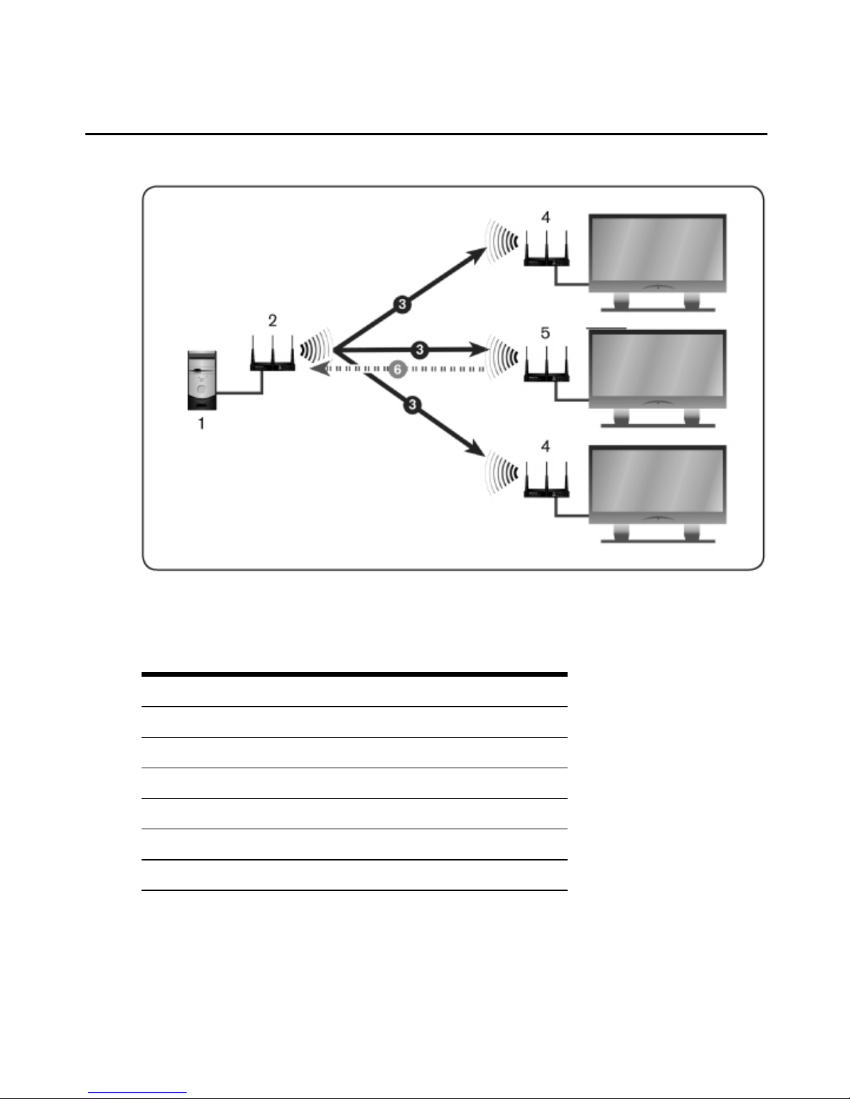
Figure 3.5: Serial Passthrough Mode
Table 3.10: Serial Passthrough Mode Descriptions
Number Item
1 Serial Device Source
2 MPXTransmitter
3 Serial Data from Transmitter to Receiver
4 MPX Receiver
5 Primary MPX Receiver
6 Serial Data from Display via Primary Receiver
Chapter 3: Operation 51
Page 60

Use the Serial Passthrough parameters section on the Serial Settings page in the Transmitter
Menu to specify the serial mode and settings.
To configure serial passthrough modes:
1. Select Serial Settings in the Transmitter Menu, located on the left side of the web interface.
2. Choose one of the following Serial Passthrough Modes from the drop-down list:
a. Disabled: Serial ports on the transmitter and receiver units are not used.
b. Simple passthru: Serial data received at the transmitter's serial port will be broadcast to
all bound receivers. Serial data will be sent only from the primary receiver to the
transmitter.
c. Primary only: Serial data received at the transmitter's serial port will be sent only to
the primary receiver. Serial data will be sent only from the primary receiver to the
transmitter.
3. Choose the serial baud rate for the local serial port from the Baud Rate drop-down list.
Baud rates up to 38.4K are supported. For baud rates over 9600, it is best to use RTS/CTS
hardware flow control.
4. Choose the serial data size for the local serial port from the Data Size drop-down list.
5. Choose the number of serial stop bits for the local serial port from the Stop Bit drop-down
list.
6. Choose the serial parity for the local serial port from the Parity drop-down list.
7. Choose the serial flow control for the local serial port from the Flow Control drop-down
list.
8. Apply the changes.
IR Control
MPX transmitters and receivers include an IR(Rx) port and an IR(Tx) port. MPX 1450/1550
transmitters and receivers feature a 2.5 mm jack for connection of an optional external IR
receiver and a 3.5 mm jack for connection of an external dual IR(Tx) emitter. IR control strings
generated from a remote controller may be forwarded across the extender network or locally
forwarded from the IR(Rx) port to the IR(Tx) port on the same MPX extender system unit.
IR extension permits a presenter to control a source device from the location of the display
device. Local loopback of IR data permits an administrator to manage display devices from the
equipment rack and/or a presenter to control a display device from the location of the display.
52 Emerge® MPX Extender System Installer/User Guide
Page 61

IR data is broadcast across the extender network from an MPX transmitter to all bound
receivers. Bi-directional IR data is limited to the transmitter and the primary receiver.
NOTE: For clarity, the flow of IR data from the IR(Rx) port to the IR(Tx) port on the same MPX extender system
unit is referred to as IR local loopback and the flow of IR data acrossthe extender network is called IR extension.
IR functionality works as follows:
• When turned on, an MPX transmitter will forward IR data detected at its IR(Rx) receiver to
all bound receivers across the extender network. This flow cannot be disabled.
• When an MPX receiver is selected as the primary receiver, IR data detected at its IR(Rx)
receiver will be forwarded across the extender network to the MPX transmitter, where it
will be emitted to the source device through the dual emitter. This IR data will not be
forwarded to other MPX receivers and this flow cannot be disabled.
• The web interface of each unit offers an IR Local Loopback setting. This setting affects IR
local loopback only. Altering this setting has no effect upon the flow of IR data across the
extender network.
The following figure illustrates the flow of IR data from the MPX transmitter to a single MPX
receiver. This data is received by all bound receivers.
NOTE: In the next three figures, 1 represents the IR(Rx) port and 2 represents the IR(Tx)port.
Chapter 3: Operation 53
Page 62

Figure 3.6: IR Flow: Transmitter to Receiver
The following figure illustrates the flow of IR data from the primary MPX receiver to the MPX
transmitter. This allows a presenter to send control strings, such as play/pause, to source devices
from the location of the display device. A single IRB-100 dual emitter is supplied with the
MPX transmitter. Should it be necessary to control more than two source devices, Avocent
offers the IRB-Y splitter, which allows two IRB-100 dual emitters to be attached to a single
MPX transmitter. Additional IRB-100 emitters may be purchased separately. The MPX
transmitter and receiver are both capable of driving up to 4 emitters (two IRB-100s) each.
54 Emerge® MPX Extender System Installer/User Guide
Page 63

Figure 3.7: IR Flow: Primary Receiver to Transmitter
The following figure illustrates local looping of IR commands. This allows source or display
devices to be controlled locally.
Chapter 3: Operation 55
Page 64

Figure 3.8: IR Lo op back
NOTE: IR data looped locally within an MPX transmitter or the primary receiver is also sent normallyacross the
extender network. IR data looped locally on a receiver other than the primary receiver will not be forwarded to the
extender network.
NOTE: The MPX extender system provides contention handling to prevent the inadvertent mixing of IR extension
data with IR loopback data. For thisreason, the localIR loopback function at an MPX receiver is temporarily
disabled while the unit is processing IR data received from the MPX transmitter. Similarly, if IR blaster mode is
enabled on a receiver, any IR data sent from the transmitter to that receiver is ignored (and not emitted) by that
receiver while it is emitting IR data detected locally by its own IR receiver port. Should contention occur, repeat the
ignored IR command via the remote control.
Configuring IR control
Use the IR Blaster section on the Configuration page in the Transmitter or Receiver menu to
enable or disable local IR loopback. IR extension is unaffected by this setting.
To configure IR control on a transmitter:
1. Select Serial Settings in the Transmitter Menu.
2. Choose one of the following IR Local Loopback modes from the drop-down list:
a. Disabled: IR local loopback is disabled.
56 Emerge® MPX Extender System Installer/User Guide
Page 65

b. Enabled: IR local loopback is enabled.
3. Apply the changes.
Regardless of the IR blaster mode setting, all IR data received by the local IR receiver port on
the transmitter is forwarded to the IRtransmit ports of all connected receivers.
To configure IR control on a receiver:
1. Select Serial Settings in the Receiver Menu.
2. Choose one of the following IR Local Loopback modes from the drop-down list:
a. Disabled: IR local loopback is disabled.
b. Enabled: IR local loopback is enabled.
3. Apply the changes.
Advanced Source Device Settings
The More Settings button on the Source Device Settings page in the Transmitter Menu provides
advanced controls for video positioning and clock phase adjustment for RGBsource devices.
NOTE: With the exception of Reset Image Settings, the advanced settings are only valid during an active RGB video
session.
The following settings are available:
• Horizontal Position: This control can be used to adjust the horizontal position of the image
on the display. The image can be moved up to 255 pixels left or right. Click Apply to
activate and store the setting.
• Vertical Position: This control can be used to adjust the vertical position of the image on
the display. The image can be moved up to seven lines up or down. Click Apply to activate
and store the setting.
• Phase: This control can be used to adjust the clock of the input video. Adjusting this
setting can improve the sharpness of objects such as text and box shapes. Click Apply to
activate and store the setting.
• Auto Image Adjust: This control will cause the transmitter to analyze the incoming video
stream and attempt to find the ideal settings.
NOTE: Before selecting this option, ensure that the screen image is not black.
1. Reset Image Settings: Use this setting to restore default settings if the results of selecting
Auto Image Adjust are not acceptable.
Chapter 3: Operation 57
Page 66

Figure 3.9: Transmitter Advanced Source Device Settings
Displaying Firmware and Hardware Versions
The Version Information page is used to display the firmware and hardware version numbers.
This page is the same for transmitters and receivers.
To display version information:
1. Select Version Information in the Transmitter Menu or Receiver Menu.
2. Check the version numbers and decide whether to proceed with a Flash upgrade. The
Firmware and Hardware Versions page displays the information described in the following
table.
Table 3.11: Firmware and Hardware Versions Page Information
Field Description
Device Name Transmitter, accesspoint or receiver name
MAC Address
L1 MAC address(control LAN) of the transmitter, accesspoint or receiver, also
printed on an external label on the unit
58 Emerge® MPX Extender System Installer/User Guide
Page 67

Field Description
Main Application
Firmware Version
Displays the current main application firmware version
Front Panel Firmware
Version
Displays the current front panel firmware version
Bootloader Firmware
Version
Displays the current bootloader firmware version
Main Board Hardware
Version
Displays the current main board hardware version. This will not change when a
firmware update is performed.
Firmware version checking
Select Version Information in the Transmitter Menu or Receiver Menu. Make note of the
firmware version of the transmitter and each bound receiver. Visit the Avocent web site at
www.avocent.com to review the available upgrades. A firmware upgrade can be performed if
the firmware on the Avocent web site is a higher revision than the version that is currently on
each of the transmitters or receivers.
Upgrading MPX firmware
The Firmware Upgrade page in the Transmitter Menu is used to download and install new
firmware. The web interface provides a means to upgrade the transmitter/access point and all
bound receivers. You must perform this procedure from the transmitter's web interface to use the
multi-units upgrade feature. You can also upgrade an MPX receiver via its own web interface.
Although the upgrade process may be initiated during an active media session, it is
recommended to disconnect the source device from the MPX transmitter prior to starting the
upgrade process. This provides additional resources and a faster upgrade process. Resources may
be freed by reducing the Maximum Video Data Rate to a low value such as 10 Mbps. This
setting is accessed via the Tuning Parameters page in the Transmitter Menu. Be sure to return
this setting to its prior value after the upgrade is complete.
Initiating an upgrade
The following steps describe how to upgrade a transmitter and any bound receivers. If access
points are used, it is important to navigate to each access point from the Transmitter Menu to
upgrade that access point and all of its bound receivers first. This is because the multi-unit
firmware upgrade feature only works across two layers. A transmitter can upgrade firmware of a
Chapter 3: Operation 59
Page 68

bound access point, but it cannot upgrade firmware of any receivers connected to that access
point.
To download the upgrade file:
1. Select Firmware Upgrade from the Transmitter Menu.
2. Type the IP address of the TFTP server from which you are downloading the new Flash
image. By default, this will be the address of the server making the request.
NOTE: TFTP is used to download the image file; to do this, it must be properly configured on the server.
3. Type the full path name of the image file to be downloaded.
NOTE: You may need to specify the file name relative to the server’sTFTP root directory.
NOTE: It is possible for a receiver or an access point to reach the TFTP server through the transmitter.
4. Apply the changes. If you provided valid parameters, the Flash upgrade process starts
downloading the image file.
NOTE: Do not turn off the transmitter while the download is in progress.
The following figure illustrates the multi-unit firmware upgrade feature, which launches
automatically. Using this page, you may select one or more MPX extender system units for
upgrade.
To upgrade MPX units:
1. Select the Update checkbox for the Transmitter Menu if you wish to upgrade its firmware.
2. The receiver selection window allows you to select options to update all receivers, only
those receivers with mismatched firmware, or manually selected receivers. Make your
selection as appropriate.
3. Once the appropriate units are selected, click the Install button to initiate the upgrade.
4. Click Cancel, if necessary, to return to the main Firmware Upgrade page. Do not turn off
the unit because it may not recover.
60 Emerge® MPX Extender System Installer/User Guide
Page 69

Figure 3.10: Transmitter Firmware Upgrade
Flash upgrade progress
The web interface offers on-going status updates throughout the upgrade process. Progress is
reported in terms of percentage of completion of each step.
Flash upgrade status LEDs
While the receiver is upgrading Flash memory, the LEDs show the current state of the Flash
upgrade. See MPX status LEDs on page 41 for more information. Each LED has a specific
pattern as follows:
• Green-2: Flashes to indicate that the upgrade is in progress and that it has not failed. While
this LED is flashing, one or more of the Green-1, Amber-2 or Amber-1 LEDs will be solid
or blinking to indicate the progress of the Flash upgrade.
Chapter 3: Operation 61
Page 70

• Green-1: Blinks while file download is in progress. It will turn solid after download has
completed.
• Amber-2: Blinks while erase or Flash of the boot image is in progress. It will turn solid
after the boot image Flash has successfully completed.
• Amber-1: Blinks while erase or Flash of the application image is in progress. It will turn
solid after the application image Flash has successfully completed.
• Red: Flashes to indicate that an error has occurred. All other LEDs are off while this LED
is flashing.
NOTE: If an error occurs at any point in the Flash upgrade processand you receive an error message, click Restart
to tryagain.
System Reboot
The System Reboot page is displayed when you select Reboot in the Transmitter Menu or
Receiver Menu.
To reboot a transmitter or receiver:
1. Click Reboot Now.
2. The reboot process will begin. A message indicates that the system reboot is in progress.
NOTE: During the reboot process, system settings are retained.
Reset to Factory Defaults
The Reset to Factory Defaults page is displayed when selected in the Transmitter Menu or
Receiver Menu.
To re-initialize a transmitter or receiver:
1. Click Re-Initialize Now.
2. The re-initialization process will begin. A message indicates that the re-initialization is in
progress.
NOTE: Resetting to factory defaults will erase all configuration information.
62 Emerge® MPX Extender System Installer/User Guide
Page 71

63
Appendix A: Technical Support
Our Technical Support staff is ready to assist you with any installation or operational issues
you encounter with your Avocent product. If an issue should develop, follow the steps below
for the fastest possible service.
To resolve an issue:
1. Check the pertinent section of this manual to see if the issue can be resolved by following
the procedures outlined.
2. Visit www.avocent.com/support and use one of the following resources:
Search the knowledge base or use the online service request.
-or-
Select Technical Support Contacts to find the Avocent Technical Support location
nearest you.
A P P E N D I C E S
Page 72

Appendix B: System Definitions
The Emerge MPX extender system consists of one transmitter, up to eight access points and up
to 64 receiver units. The following terms are used to identify common components.
Table B.1: Definitions for an MPX Extender System Solution
Term Definition
Access Point
An expansion unit for the MPXextender system that is situated between the
transmitter and up to eight receivers.
Active EDID
A merged EDID string that describes the subset of characteristicssupported by
the primary display device and the MPX transmitter.
Bound
Receiver
A receiver that is actively connected to a transmitter over a wired or wireless link.
Control LAN
A LAN interface on an MPX receiver or transmitter that allows accessto its onboard web interface. On MPX transmitters and accesspoints, this is labeled L1.
On MPX receivers, a single LAN port, indicated by the LANsymbol, provides the
combined functionsof media LAN and control LAN.
Default EDID
Factory default EDID information stored in an MPX transmitter, which describes
the supported video characteristics of the transmitter.
Display
Device
Video projector, plasma, LCD display or other displaydevice.
EDID
Extended DisplayIdentification Data: A Video ElectronicsStandards Association
(VESA) standard data format that contains basicinformation about a display
device and its capabilities, including vendor information, maximum image size,
color characteristics, factory pre-set timings, frequencyrange limits and
character strings for the monitor name and serial number.
Extender
Group
A term denoting an MPX transmitter and access point and allof its bound
receivers, whether wired orwireless.
Extender
Network
A term denoting a wired or wirelessmedia LAN.
HDCP
High-Bandwidth DigitalContent Protection (HDCP) is a form of digital rights
management used to secure digital audio and video content .
64 Emerge® MPX Extender System Installer/User Guide
Page 73

Term Definition
IR Blaster
Dual IR emitter that connects to the IR(Tx) port of the transmitter or the receiver
and converts electrical signalsthat arrive at that port to IR signalsfor control of
source and display devices.
IR Extension Flow of IR data across the MPX extender system.
IR Local
Loopback
Flow of IR data from the IR(Rx) receiver to the IR(Tx) port on the same unit.
IR Remote Remote control that transmits device control information using an infrared LED.
IR(Rx) port
An infrared receiver port located on the front panel of MPXtransmitters and
receivers in the form of a 2.5 mm mini jack. An optional receiver may be attached
to transmitters or receivers via this port.
IR(Tx) port
An infrared emitter port located on the front panel of MPXtransmitters and
receivers.
Media LAN
A LAN port on an MPX receiver or transmitter that serves as an interface for a
wired network for transmission of A/V media. This port is labeled L2 on MPX
transmitters and indicated by a LAN symbol on receivers. The Media LAN and
Control LAN functions share the same port on receivers. On accesspoints, the
inbound Media LAN and Control LAN functions share the L1 port, while the
outbound Media LAN uses the L2 port.
MPX
Extender
System
A genericterm denoting an MPX transmitter, accesspoint or receiver.
Primary
Display
Device
A display device attached to the primary MPX receiver.
Primary EDID
EDID information received from the primary displaydevice, which describes the
characteristics of the display device.
Appendices 65
Page 74

Term Definition
Primary
Receiver
A single MPX receiver that you specify as the primary receiver during
configuration for each system. Only the primary receiver reports EDID
information back to the transmitter and source device. T he primary receiver is
the only receiver capable of bi-directional IR transfers and bi-directional RS-232
serial transfers with the MPX transmitter.
Receiver
An MPX extender system unit that inputs media from a transmitter, decrypts,
uncompresses, converts and manipulates the data back into the desired format
and outputs it to the connected supported displaydevices.
Source
Device
Computer, HD-DVD or other source of A/V content.
Transmitter
An MPX extender system unit that inputs media from a source device, encrypts,
compresses and transmits the content to an MPX receiver. MPX transmitters
also provide a backchannel for transmission of control data backto a source
device.
Transmitter
Number
An attribute of a transmitter that enables multiple extender groups to co-exist on
the same wired media LAN.
Universal A/V
Port
A DVI-I media input or output port on a transmitter or receiver that can be
configured to support a range of video formats, including HDMI, DVI-D, DVI-A,
RGB and Component.
Wired Link
A 10/100 Mbps wired Ethernet connection between a transmitter and bound
receivers/access points, or between an access point to bound receivers.
WirelessLink
An wireless connection between an MPX transmitter or access point and bound
receivers (supported on the MPX 1550 extender system only).
66 Emerge® MPX Extender System Installer/User Guide
Page 75

Appendix C: Supported ISO Country Codes
Table C.2: MPX Extender System Supported ISO Country Codes
Country ISO Code
Country
ISO Code
North America
Malta MT
United States US
Netherlands NL
Canada CA
Norway NO
Europe
Poland PL
Austria AT
Portugal PT
Belgium BE
Russia RU
Cyprus CY
Slovakia SK
Czech Republic CZ
Slovenia SI
Denmark DK Spain
ES
Estonia EE
Sweden SE
Finland FI
Switzerland CH
France FR
Turkey TR
Germany DE
UK GB
Greece GR
Asia / Pacific
Hungary HU
Australia AU
Ireland IE
China (PRC) CN
Italy IT
Hong Kong HK
Latvia LV
India IN
Lithuania LT
Indonesia ID
Luxembourg LU
Japan JP
Appendices 67
Page 76

Country ISO Code
Country
ISO Code
Korea KR Africa / Middle East
Malaysia MY Saudi Arabia SA
New Zealand NZ Dubai / UAE AE
Philippines PH Latin / South America
Singapore SG Argentina AR
Taiwan TW Brazil BR
Mexico MX
68 Emerge® MPX Extender System Installer/User Guide
Page 77

Appendix D: Technical Specifications
Table D.3: MPX 1450/1550 Transmitter, Receiver and Access Point Product Specifications
Physical Attributes
Height 1.0"
Width 6.92"
Depth 4.55"
Ambient Atmospheric Condition Ratings
Operating Temperature 32°F - 104°F (0°C - 40°C)
Storage Temperature -04°F - 140°F (-20°C- 60°C)
Humidity
20% to 80% relative humidity(non-condensing) across the operating
temperaturerange
Altitude
10,000 ft across the operating temperature range; 35,000 ft across storage
temperature range
Shock 140 G - 3 axis
Power Supply
AC-input 100 - 240 VAC
AC Frequency 50 - 60 Hz
Inrush Current 14.2 Amps (AC/DC adaptor)
Connections (front)
2.5 mm Mini-jack IR input (optional IR-RX adaptor with 1m cable is required): 38 KHz +/- 2 KHz
3.5 mm Mini-jack
IR blaster output, 38 KHz +/- 2 KHz; the IR blaster port supports enough drive
current to handle four IR LEDs
RP-SMA Connector (2) Antenna connectors
USB USB 1.1 (Reserved for future use)
Appendices 69
Page 78

Physical Attributes
Connections (rear)
Power DC barrel connector
Serial (RJ-45)
Dual serial port for control of attached display devices. Requires optional DB9-
DUAL female serial cable
LAN (RJ-45)
Ethernet connector 10/100 IEEE 802.3, used for streaming video and web
access
DVI-I A/V output port that supports a wide range of digital and analog video modes
RCA Jacks (2) Left and right jacksfor unbalanced analog audio
S/PDIF Digital audio output. Operation of this port may require a firmware upgrade
Video
Video Gain Unity ±1DB
Video Resolutions
(RGB)
Supports the following RGB video resolutions:
Computer (RGB) resolutions(at 30 frames per second):
640 x 480 @ 60 Hz
800 x 600 @ 60 Hz
1280 x 720 @ 60 Hz
1280 x 768 @ 60 Hz
1360 x 768 @ 60 Hz
SD video (RGB) resolutions (at 30 frames per second):
480 p @ 60 Hz
576 p @ 50 Hz
HD video (RGB) resolutions (at 30 frames per second):
720 p @ 50/60 Hz
70 Emerge® MPX Extender System Installer/User Guide
Page 79

Physical Attributes
Video Resolutions(Component
Video)
SD video (Component) resolutions (at 30 frames per second):
480 i @ 60 Hz
480 p @ 60 Hz
576 i @ 50 Hz
576 p @ 50 Hz
HD video (Component) resolutions (at 30 frames per second):
720 p @ 50/60 Hz
1080 i @ 50/60 Hz
Video Resolutions
(HDMI and DVI-D)
Supports the following HDMI and DVI-D resolutions:
Computer resolutions(at 30 frames per second):
640 x 480 @ 60 Hz
800 x 600 @ 60 Hz
1280 x 720 @ 60 Hz
1280 x 768 @ 60 Hz
1360 x 768 @ 60 Hz
SD video resolutions (at 30 frames per second):
480 i @ 60 Hz
480 p @ 60 Hz
576 i @ 50 Hz
576 p @ 50 Hz
HD video resolutions (at 30 frames per second):
720 p @ 50/60 Hz
1080 i @ 50/60 Hz
Audio
Sensitivity Line audio inputs less than or equal to 10K Ohm with 0-36 db of headroom
Appendices 71
Page 80

Physical Attributes
Frequency Response
Analog audio frequency response: 20 Hz - 20 Khz with a 3 dB per octave roll-
off beginning at 14 Khz
Supported Radio Bands (MPX 1550 extender system only)
UNII 1: (4 Channels) 5.15-5.25 GHz: channels bonded into two 40 GHz channels
UNII 2: (4 Channels) 5.25-5.35 GHz: channels bonded into two 40 GHz channels
UNII 3: (4 Channels) 5.725 to 5.825 GHz: channels bonded into two 40 GHz channels
Safety and EMC Approvals
and Markings
Regulatory Compliance [Compliance Model Number (CMN): 2003 and 2004
Series]:
FCC Class B, UL, cUL, RoHS, CE, ICES-003, WEEE
72 Emerge® MPX Extender System Installer/User Guide
Page 81

Appendix E: Video Troubleshooting
The following troubleshooting tips should help resolve most common setup and initialization
issues. If a problem persists, please contact Avocent technical support for additional help.
Available information
The Transmitter Status table on the Connection Status page in the Transmitter Menu offers
additional information for video troubleshooting. If video is actively being processed by the
transmitter, the A/V Source Resolution field indicates the current resolution. An asterisk
appears after the field name (A/V Source Resolution*) if a non-standard resolution is detected.
Appendices 73
Page 82

Figure E.1: Transmitter Status Table
If you click Help, the Transmitter Status table provides three additional fields:
74 Emerge® MPX Extender System Installer/User Guide
Page 83

• Primary Video Resolutions: This field contains a list of all resolutions reported to the
transmitter by the primary receiver. These values come from the display device or from the
Display Device Settings page in the Receiver Menu.
• Video Resolutions in Use: This field indicates the list of resolutions reported to the source
device.
• RGB Video Resolutions Stored: This field indicates the resolutions currently stored in the
Active EDID string of the transmitter.
The Source Device Settings page in the Transmitter Menu provides advanced settings for
explicit control of image positioning (horizontal and vertical panning) and video clock phase
adjustment.
The Transmitter Performance and Receiver Performance tables on the Media LAN Performance
page in the Transmitter Menu provide real-time status updates of media LAN bandwidth
utilization. The Current Video Data Rate is the target transmit data rate. This value should fall
between the maximum data rate and the minimum data rate settings.
The Transmitted Total Bitrate is the amount of audio and video data transmitted per second
since the last page update. Bitrate status for retransmitted data is also provided. The receiver
table indicates the amount of real-time data received from the media LAN and the amount of
retransmitted, recovered and lost data. Chronic status of missing data is a symptom of an
adverse condition that should be diagnosed and resolved.
Common issues and solutions
Video is restricted to 640 x 480
This is an indication that the MPX transmitter has not received valid EDID information from
the display device. Try the following actions to remedy the situation.
• It is possible that the source device obtained EDID information from the MPX transmitter
before device information was obtained from the display device. To resolve this, follow the
suggested sequence for turning on the units as provided in Initiating a Media Session on
page 37.
• If the display device is not Plug and Play ready, it may not offer EDID information. The
Display Device Settings page in the Receiver Menu will indicate if the display device is
not Plug and Play ready. In this case, use the provided table to enable appropriate
resolutions for the display device. Be careful not to enable resolutions that the display
cannot support.
• The display device may have submitted an improperly formed EDID string. Should this
happen, the transmitter will discard the entire string and the default EDID will remain in
Appendices 75
Page 84

effect. In this case, use the Display Device Settings table to enable appropriate resolutions
for the display device.
• Pins 12 and 15 of an RGB cable provide connectivity for DDC data and DDC clock,
respectively. EDID information is passed via the DDC channel. The RGBcable may be
damaged or unable to pass data on the DDCchannel. Verify proper operation of your RGB
cable.
Video is not properly centered
This is an indication that the video resolution differs slightly from VESA standards. In this
case, the MPX transmitter may not properly detect the start and end of the video frame. Use the
advanced settings on the Source Device Settings page in the Transmitter Menu to properly
center the image.
No video is visible
This is an indication that the display device is either not properly connected or is not
compatible with the MPX extender system. The following steps may help to resolve this issue.
For all display devices:
• Launch your browser to the Connection Status page in the Transmitter Menu. Helpful error
information may be displayed in the Transmitter Status table.
• Connect a display device directly to your source device. If active media is not displayed,
resolve the issue before attempting to extend the signal. If active media is present, verify
proper operation of any transmitter and receiver video cables and adaptors.
• Turn off all receivers other than the primary. Working with a reduced network will allow
you to simplify the troubleshooting environment.
• View the resolution and frame rate information in Technical Specifications on page 69 to
determine if your source device is operating within supported parameters.
• If you have selected wireless operation, select a different channel in the Media LAN
Settings page in the Transmitter Menu to ensure that there is not a conflict with other
nearby wireless devices.
• If you are using an MPX 1450 extender system, try using a wired media LAN to check for
possible radio-relatedissues.
• Make sure that you have selected a primary receiver, which is responsible for generation of
EDID information for the source device.
For HDMI or DVI-D display devices:
76 Emerge® MPX Extender System Installer/User Guide
Page 85

• Initiate a video hot-plug of the source and display devices to ensure that the EDID
information has been read and transferred across the extender network.
• Determine if the source device is sending HDCPprotected content. If so, no video will be
displayed because the system does not support HDCP protected content.
• If only one display is not working, try making it the primary display. Perform a hot-plug of
the video connection (HDMI, RGB). If the problem is resolved and the displays are
different models, there may be an incompatibility between the options these monitors
support.
Fine tuning suggestions
The following table provides detailed instructions for tuning your MPX extender system units.
If your application requires only one receiver and you have not yet configured your transmitter
for 1-to-1 topology, you should do so at this time. The Video Data Rate setting on the Tuning
Parameters page may be used to increase visual acuity.
If you are fine
tuning...
Then choose...
choppy video for a
wired or wireless
connection
Select Wireless Video Data Rate settings on the Tuning Parameters page in the
Transmitter Menu. See Transmitter/access point tuning parameters on page 46.
Choppy video is the result of lost data. The receiver will continue to output the last fully-
received frame untila complete new frame is received. This is not noticeable for a still
image, such as a spreadsheet, but it is particularly noticeable for a motion video. Audio
playbackrequires minimal bandwidth and typicallyplays smoothly, even when motion
video is choppy.
To restore smooth video playback, adjust the minimum data rate setting downward as
needed to obtain a constant frame rate of 24 fps or greater under adverse conditions.
Lowering the minimum setting allows you to maintain constant frame rate by slightly
softening the image during adverse media LAN conditions. As conditionsimprove, the
transmitter will graduallyraise the video data rate.
Retransmission requests may stem from a temporary signal blockage, such as a box
being placed in front of the transmitter. Wireless channel contention may also cause
data interference. If interference becomes chronic, you may want to consider antenna
extension cables or selection of a different wireless channel to relieve the condition.
Table E.4: Methods for Fine Tuning
Appendices 77
Page 86

If you are fine
tuning...
Then choose...
sharpness of computer
graphics
Select Luma Chroma Percentages and Content Type on the Tuning Parameters
page in the Transmitter Menu. See Transmitter/access point tuning parameters on
page 46.
The luma chroma setting affectsthe way in which the transmitter processes luma and
chroma information in the input video stream. By default, 67% of the output stream is
dedicated to luma information and 33% of the output stream is dedicated to chroma
information. This ratio is well suited for a combination of motion video and some
computer graphics. For applications that are heavilyslanted toward still graphic
images with sharp edges, you may have better resultsby increasing luma to 80%.
Experiment with the slider bar to find the settings that work best for yourapplication.
Select Content Type to choose an encoding algorithm that is geared toward computer
graphics (still images) or motion video.
For RGB source devices, select Phase control on the Source Device Settings page in
the Transmitter Menu to optimize the sharpnessof objects such as text and box
shapes.
wireless channel
contention resulting
from other wireless
devices
Select a wirelesschannel from the drop-down list on the BasicLANSettings tab of the
Media LAN Settings page in the Transmitter Menu.
Channel contention arising from other devicesoperating in the same channel may
cause excessive dropped video frames. Selecting an unused channel will resolve this
issue.
Available channels may be selected from a drop-down list. The selected channel will
be used by the transmitter and bound receivers. Once changed, the media session will
drop and bound receivers will enter a search mode. After the transmitter is detected,
the session will continue normally.
78 Emerge® MPX Extender System Installer/User Guide
Page 87

If you are fine
tuning...
Then choose...
wireless transmission
power settings
Adjust the T ransmit Power Attenuation field on the BasicLANSettings tab of the
Media LAN Settings page. This setting may be set separately for transmitters and
receivers.
The transmit power attenuation is determined by the transmitter’s Country Code
setting (MPX 1550 extender system only). Controls are provided to reduce transmit
power.
Higher transmit power attenuation reduces the range of a transmitter’s influence,
making the frequency available for the transmitter/receiver to use the same frequency
in neighboring rooms. Lower attenuation values allow for increased distance and wall
penetration between transmitters and receivers.
The default power setting may overdrive radio receivers when MPX transmitters and
receivers are positioned in close proximity to each other, within ten feet or less, as
might be the case during initial configuration and in small conference rooms. Over-
driven signalsmay result in lost frames or, in extreme cases, dropped connections. To
avoid such errors, select the highest attenuation setting that resultsin a stable,
acceptable image. Remember to raise transmit power levels when extender system
units are placed in their final locations.
Additional tips for RGB display devices
Display devices differ widely in their support of video resolution, refresh rates, color depth and
other configurable features. To allow source and display devices to negotiate available settings
in a Plug and Play manner, the industry has adopted a display data channel, or DDCstandard.
The DDC standard supported by MPX extender systems is DDC2B. This standard is adhered to
by most RGB, DVI, and HDMI display devices. Compliant display devices contain a PROM
that can be read by a source device across a display data channel (DDC). The PROM contains
formatted information about the capabilities of the display. This information is commonly
referred to as Extended Display Information Data (EDID).
DVI-D and HDMI source devices will dynamically query this information when a display
device hot-plug event is detected so displays are immediately available. However, most RGB
computer source devices such as graphics cards query information only once they turn on. For
this reason, it is particularly important that EDID information is passed through the extender
network and assembled by the transmitter into the Active EDID string before the RGB source
Appendices 79
Page 88

device is turned on. Therefore, the power sequence of MPX transmitters, receivers, access
points, source devices and display devices iscritical when using an RGB source device.
NOTE: EDID information is maintained by the MPX transmitter in non-volatile storage so the order in which you turn
on the unitsis important only during initialinstallation.
If you followed the recommended procedure for turning on the units and no video is visible at
the display device, then the following tips may help to resolve any issues.
• When set for Plug and Play, MPX receivers are able to detect the presence of an RGB
display device from the display's EDID information. If the display does not offer
DDC/EDID support or if the MPX receiver is unable to read EDID information from the
display, then you must select the Manual (RGB) option. Otherwise, the MPX receiver will
assume that a display device is not present and will not establish a video session.
• The RGB source device may be operating at a resolution not supported by the MPX
transmitter.
• If your source device is a laptop computer, toggle the video back to the laptop display
and check the resolution of the secondary monitor. To test the connection between the
transmitter and the receiver, change the secondary monitor setting to 640 x 480 at 60
Hz resolution. Toggle the video to the RGB connector again. Video should appear
within 30 seconds.
• If your source device is a desktop computer or server, then you must disconnect the
MPX transmitter from its RGB port and connect an RGB monitor in its place. It may
be necessary to reboot the computer to establish video. Change the resolution to 640 x
480 at 60 Hz. After changing the resolution on the computer, turn it off and reconnect
the MPX transmitter to the computer's RGB source. Turn on the computer.
• After you've obtained video at the 640 x 480 at 60 Hz resolution, change the
resolution on the RGB source to one of the other supported resolutions.
80 Emerge® MPX Extender System Installer/User Guide
Page 89

590-974-501B
For Technical Support:
www.avocent.com/support
 Loading...