

Page 1

DS R® Switch
Installer/User Guide
For models: DSR1030 DSR2030 DSR4030 DSR8030
Guide d’installation et d’utilisation
Pour les modèles DSR1030 DSR2030 DSR4030 DSR8030
Page 2
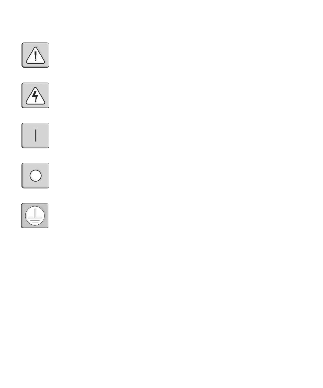
INSTRUCTIONS
This symbol is intended to alert the user to the presence of important operating and
maintenance (servicing) instructions in the literature accompanying the appliance.
DANGEROUS VOLTAGE
This symbol is intended to alert the user to the presence of uninsulated
dangerous voltage within the product’s enclosure that may be of sufficient
magnitude to constitute a risk of electric shock to persons.
POWER ON
This symbol indicates the principal on/off switch is in the on position.
POWER OFF
This symbol indicates the principal on/off switch is in the off position.
PROTECTIVE GROUNDING TERMINAL
This symbol indicates a terminal which must be connected to earth ground
prior to making any other connections to the equipment.
Page 3

DSR® Switch
Installer/User Guide
For models: DSR1030, DSR2030, DSR4030, DSR8030
Avocent, the Avocent logo, The Power of Being There, DSR, DSView
and OSCAR are registered trademarks of Avocent Corporation or its
affiliates. All other marks are the property of their respective owners.
2005 Avocent Corporation. All rights reserved. 590-472-616A.
Page 4
USA Notification
Warning: Changes or modifications to this unit not expressly approved by the party responsible for compliance
could void the user’s authority to operate the equipment.
Note: This equipment has been tested and found to comply with the limits for a Class A digital device,
pursuant to Part 15 of the FCC Rules. These limits are designed to provide reasonable protection against
harmful interference when the equipment is operated in a commercial environment. This equipment generates,
uses and can radiate radio frequency energy and, if not installed and used in accordance with the instruction
manual, may cause harmful interference to radio communications. Operation of this equipment is a residential
area is likely to cause harmful interference, in which case the user will be required to correct the interference at
his/her own expense.
Canadian Notification
This Class A digital apparatus complies with Canadian ICES-003.
Cet appareil numérique de la classe A est conforme à la norme NMB-003 du Canada.
Japanese Notification
Korean Notification
Safety and EMC Approvals and Markings
UL, FCC, cUL, ICES-003, CE, GS, VCCI, MIC, C-Tick, GOST
Page 5

TABLE OF CONTENTS
List of Figures .................................................................................................................. v
List of Tables ..................................................................................................................vii
Chapter 1: Product Overview.......................................................................................... 1
Features and Benefits .................................................................................................................1
Safety Precautions ......................................................................................................................4
Chapter 2: Installation ..................................................................................................... 5
Installation Overview..................................................................................................................5
Getting Started............................................................................................................................ 7
Connecting the DSR Switch Hardware.......................................................................................8
Verifying the Connections......................................................................................................... 10
Configuring DSView Software and Adjusting Mouse Settings.................................................10
Chapter 3: Local Port Operation................................................................................... 13
Controlling Your System at the Local Port .............................................................................. 13
Viewing and Selecting Ports and Servers.................................................................................13
Navigating the OSCAR Interface..............................................................................................16
Configuring OSCAR Interface Menus ......................................................................................18
Setting Virtual Media Options.................................................................................................. 33
Managing Server Tasks Using the OSCAR Interface ...............................................................35
iii
Chapter 4: Terminal Operations ................................................................................... 41
The Console Menu .................................................................................................................... 41
Other Console Main Menu Options.......................................................................................... 44
Appendices..................................................................................................................... 47
Appendix A: FLASH Upgrades................................................................................................. 47
Appendix B: Using DSView Software Over a Modem Connection .......................................... 49
Appendix C: Using DSRIQ-SRL Modules ................................................................................50
Appendix D: UTP Cabling........................................................................................................54
Appendix E: Technical Specifications ...................................................................................... 56
Appendix F: Sun Advanced Key Emulation..............................................................................58
Appendix G: Technical Support................................................................................................60
Index................................................................................................................................ 61
Page 6

iv DSR Switch Installer/User Guide
Page 7

LIST OF FIGURES
Figure 1.1: Example DSR Switch Configuration............................................................................... 3
Figure 1.2: DSR Switch Model Comparison ..................................................................................... 3
Figure 2.1: Basic DSR Switch Configuration....................................................................................6
Figure 3.1: Main Dialog Box ..........................................................................................................14
Figure 3.2: Setup Dialog Box.......................................................................................................... 18
Figure 3.3: Names Dialog Box........................................................................................................ 19
Figure 3.4: Name Modify Dialog Box ............................................................................................. 20
Figure 3.5: Devices Dialog Box ...................................................................................................... 21
Figure 3.6: Device Modify Dialog Box ........................................................................................... 22
Figure 3.7: Menu Dialog Box.......................................................................................................... 23
Figure 3.8: Flag Dialog Box ........................................................................................................... 24
Figure 3.9: Position Flag ................................................................................................................ 25
Figure 3.10: Broadcast Dialog Box ................................................................................................26
Figure 3.11: Scan Dialog Box......................................................................................................... 27
Figure 3.12: Commands Dialog Box...............................................................................................29
Figure 3.13: Screen Saver Dialog Box............................................................................................30
Figure 3.14: Keyboard Dialog Box.................................................................................................32
Figure 3.15: Virtual Media Dialog Box ..........................................................................................34
Figure 3.16: Commands Dialog Box...............................................................................................35
Figure 3.17: User Status Dialog Box .............................................................................................. 36
Figure 3.18: Disconnect Dialog Box...............................................................................................37
Figure 3.19: Version Dialog Box ....................................................................................................38
Figure 3.20: DSRIQ Selection Dialog Box...................................................................................... 39
Figure 3.21: DSRIQ Version Dialog Box........................................................................................39
Figure 4.1: Console Main Menu......................................................................................................42
Figure 4.2: Network Configuration Menu.......................................................................................43
v
Page 8

vi DSR Switch Installer/User Guide
Page 9

LIST OF TABLES
List of Tables
Table 3.1: Main Dialog Box Functions ........................................................................................... 14
Table 3.2: OSCAR Interface Status Symbols...................................................................................15
Table 3.3: OSCAR Interface Navigation Basics ..............................................................................16
Table 3.4: Setup Features to Configure the OSCAR Interface........................................................ 18
Table 3.5: OSCAR Interface Status Flags ....................................................................................... 24
Table 3.6: Virtual Media Options....................................................................................................33
Table 3.7: Commands to Manage Routine Tasks for Your Target Device(s)..................................35
Table C.1: DSRIQ-SRL Module Pinouts ........................................................................................53
Table D.1: UTP Wiring Standards ................................................................................................. 54
Table E.1: DSR Switch Product Specifications ..............................................................................56
Table F.1: Sun Key Emulation ........................................................................................................ 58
Table F.2: PS/2-to-USB Keyboard Mappings ................................................................................ 59
vii
Page 10

viii AV2000 Installer/User Guide
Page 11

CHAPTER
Product Overview
1
Features and Benefits
Avocent DSR® switches combine analog and digital technology to provide flexible, centralized
control of data center servers and virtual media, and to facilitate the OA&M (operations, activation
and maintenance) of remote branch offices where trained operators may be unavailable. They
provide enterprise customers with a significant reduction of cable volume, secure remote access
and flexible server management from anywhere at anytime.
Each DSR switch model consists of a rack mountable keyboard, video and mouse (KVM) switch,
configurable for analog (local) or digital (remote) connectivity. Video resolutions are supported
up to 1280 x 1024 for remote users. Enhanced video quality of up to 1600 x 1200 is available
to local users via the video port.
The DSR switch has user peripheral ports for PS/2 and USB keyboards and mice, and an SPC port
that may be used to connect to an SPC power control device. An SPC device is an 8- or 16-outlet
device that can be used to control the power state of any attached target devices using the DSView
management software. Additionally, virtual media such as generic removable media and CDROM
drives can be connected to any one of five USB ports.
The DSR switches work over standard LAN connections. Users can access target devices
across a 1000BaseT LAN port that is used to establish an Ethernet connection, or directly
through a local port. Each DSR switch model includes a MODEM port that supports V.34, V.90
or V.92-compatible modems that may be used to access the switch when an Ethernet
connection is not available.
The IP-based DSR switches give you flexible target device management control from anywhere in
the world.
1
®
Reduce cable bulk
With server densities continually increasing, cable bulk remains a major concern for network
administrators.The DSR switches significantly reduce KVM cable volume in the rack by utilizing
the innovative DSRIQ module and single, industry-standard Unshielded Twisted Pair (UTP) CAT
5 cabling. This allows a higher server density while providing greater airflow and cooling capacity.
The DSRIQ module is powered directly from the target device and provides Keep Alive
functionality when the DSR switch is not powered.
Page 12

2 DSR Switch Installer/User Guide
The DSRIQ-SRL (serial) module is a DCE device that provides the primary interface between a
serial device and a DSR switch. It provides VT100 terminal emulation, break suppression and port
history in a compact, convenient module.
Control of virtual media-capable appliances
The DSR switch allows you to view, move or copy data located on virtual media to and from any
server. This feature allows you to manage remote systems more efficiently by allowing operating
system installation, operating system recovery, hard drive recovery or duplication, BIOS updating
and server backup.
Virtual media can be connected directly to the DSR switch using one of five USB ports located on
the switch. In addition, virtual media may be connected to any remote workstation that is running
DSView
NOTE: To open a virtual media session with a server, the server must first be connected to the switch using a
virtual media capable DSRIQ module (USB2 or USB2L).
®
management software and is connected to the DSR switch using an Ethernet connection.
Access the DSR switch via network connection
No special software or drivers are required on the attached, or client, computers.
NOTE: The client connects to the server housing the DSView management software using an Internet browser.
For modem access, you must install DSR Remote Operations software included on the DSView software CDROM (see the DSView Installer/User Guide for more information).
Users access the DSR switch and all attached systems via Ethernet or using a V.34, V.90 or V.92
modem from a client computer, such as a PC. Clients can be located anywhere a valid network
connection exists.
Simple access to any target device
When a user accesses the DSView Server software, a listing of all target devices to which the user
has permission to view and manage is displayed. When a user selects a target device from the list,
the video of the selected target device is displayed in a Video Viewer window.
Page 13

DSR Switch
Chapter 1: Product Overview 3
Modem
Telephone
Analog User
(OSCAR® Graphical
User Interface)
Figure 1.1: Example DSR Switch Configuration
Switch
Model
DSR1030 16 1 1 1 1
DSR2030 16 2 1 1 2
DSR4030 16 4 1 1 4
DSR8030 16 8 1 1 8
Network
Number
Servers
Ethernet
of
DSView
Software Server
Digital User
(Computer with Internet browser)
Local
Digital
Paths
Analog
User
Virtual
Media
Sessions
Sessions
Remote
Virtual
Media
Figure 1.2: DSR Switch Model Comparison
Page 14

4 DSR Switch Installer/User Guide
Safety Precautions
To avoid potential video and/or keyboard problems when using Avocent products:
• If the building has 3-phase AC power, ensure that the computer and monitor are on the same phase.
For best results, they should be on the same circuit.
To avoid potentially fatal shock hazard and possible damage to equipment, please observe the
following precautions:
• Do not use a 2-wire power cord in any Avocent product configuration.
• Test AC outlets at the target device and monitor for proper polarity and grounding.
• Use only with grounded outlets at both the target device and monitor. When using a backup
Uninterruptible Power Supply (UPS), power the target device, the monitor and the DSR switch from
the UPS.
NOTE: The AC inlet is the main power disconnect.
Rack mount safety considerations
• Elevated Ambient Temperature: If installed in a closed rack assembly, the operating temperature of
the rack environment may be greater than room ambient. Use care not to exceed the rated maximum
ambient temperature of the switch.
• Reduced Air Flow: Installation of the equipment in a rack should be such that the amount of airflow
required for safe operation of the equipment is not compromised.
• Mechanical Loading: Mounting of the equipment in the rack should be such that a hazardous
condition is not achieved due to uneven mechanical loading.
• Circuit Overloading: Consideration should be given to the connection of the equipment to the supply
circuit and the effect that overloading of circuits might have on overcurrent protection and supply
wiring. Consider equipment nameplate ratings for maximum current.
• Reliable Earthing: Reliable earthing of rack mounted equipment should be maintained. Pay
particular attention to supply connections other than direct connections to the branch circuit (for
example, use of power strips).
Page 15

CHAPTER
2
The DSR switching system requires connectivity to a server running the DSView Server software.
DSView software allows a user to view and control target devices (one at a time) attached to the
DSR switching system. For more information on the DSView software, see the DSView
Installer/User Guide.
The DSR switching system transmits keyboard, video and mouse (KVM) information between
operators and target devices attached to the DSR switch over a network using either an Ethernet
connection or a modem connection.
The DSR switch uses TCP/IP for communication over Ethernet. Although 10BaseT Ethernet may
be used, Avocent recommends a dedicated, switched 100BaseT network, or even a
1000BaseT network.
The DSR switch uses the Point-to-Point Protocol (PPP) for communication over a V.34, V.90 or
V.92 modem.
5
Installation
Installation Overview
The general procedure for setting up and installing the DSR switch is as follows:
• Unpack the DSR switch and verify that all components are present and in good condition. See
the Getting Started section in this chapter.
• Make all hardware connections between the power source, DSR switch, target devices,
optional SPC device, the Ethernet and the optional modem connection. See the Connecting the
DSR Switch Hardware section.
• Turn on the power and verify that all connections are working. See the Verifying the
Connections section.
• If you are configuring the DSR switch using the console menu interface, do that at this point.
See Chapter 4 for more information.
• Use the DSView Server software to configure the DSR switch. See the DSView Installer/User
Guide for detailed instructions.
• Make the appropriate mouse setting adjustments. See the Adjusting mouse settings on target
devices section.
Page 16
6 DSR Switch Installer/User Guide
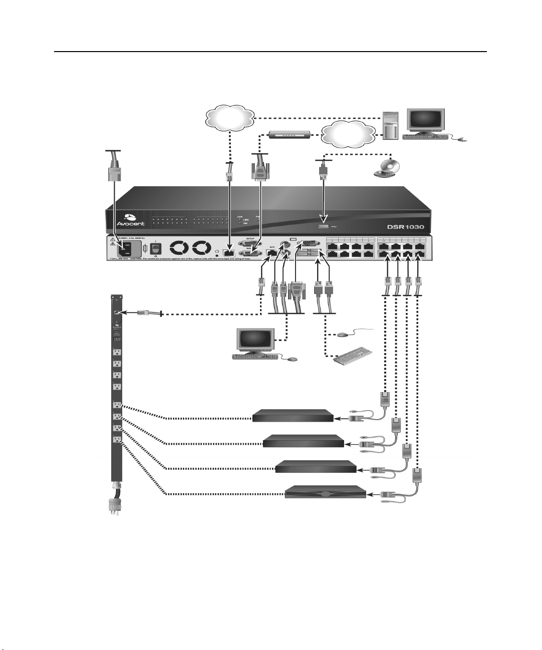
The following diagram illustrates one possible configuration for your DSR switch.
Power
Cord
Ethernet
Modem
Telephone
Network
Digital User
DSR 1030 Switch
SPC Port
Connection
SPC
Power Control
Analog User
Device
Servers 1-16
* To open a virtual media session with a server,
the server must first be connected to the switch
using a virtual media capable DSRIQ module
(USB2 or USB2L).
Ports
1-16
CAT 5
Cable
DSRIQ Modules
PS/2, USB*, Sun
and serial adaptors
are available.
Figure 2.1: Basic DSR Switch Configuration
Page 17

Setting up your network
The DSR switching system uses IP addresses to uniquely identify the switch and the target devices.
The DSR switch supports both Dynamic Host Configuration Protocol (DHCP) and static IP
addressing. Avocent recommends that IP addresses be reserved for each switch and that they
remain static while the DSR switches are connected to the network. For additional information on
setting up the DSR switch using the DSView Server software, and for information on how the DSR
switch uses TCP/IP, see the DSView Installer/User Guide.
Getting Started
Before installing your DSR switch, refer to the following lists to ensure you have all items that shipped
with the DSR switch, as well as other items necessary for proper installation.
Supplied with the DSR switch
• Local country power cord
• Rack mounting brackets
• Null modem cable
• DSR Installer/User Guide (this manual)
• DSR Quick Installation Guide
Additional items needed
Chapter 2: Installation 7
• One DSRIQ module per target server or DSRIQ-SRL module per serial device
• One CAT 5 patch cable per DSRIQ module (4-pair UTP, up to 10 meters)
• One CAT 5 patch cable for network connectivity (4-pair UTP, up to 10 meters)
• One USB2 or USB2L DSRIQ module per target server for virtual media sessions
• DSView software
• (Optional) V.34, V.90 or V.92-compatible modem and cables
• (Optional) SPC power control device
Page 18
8 DSR Switch Installer/User Guide
Connecting the DSR Switch Hardware
NOTE: The DSR switch may be rack mounted in a 1U configuration. The DSR switch does not support a
0U configuration.
To connect and power up your DSR switch:
1. Power down the target device(s) that will be part of your DSR switching system. Locate the
power cord that came with the DSR switch. Plug one end into the power socket on the rear of
the DSR switch. Plug the other end into an appropriate AC wall outlet.
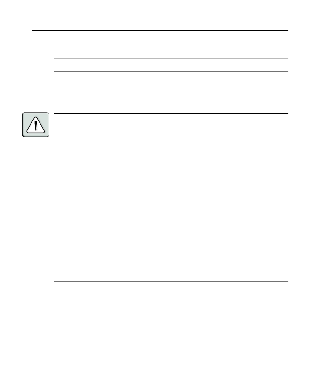
WARNING: To reduce the risk of electric shock or damage to your equipment:
- Do not disable the power cord grounding plug. The grounding plug is an important safety feature.
- Plug the power cord into a grounded (earthed) outlet that is easily accessible at all times.
- Disconnect the power from the switch by unplugging the power cord from either the electrical outlet or
the appliance.
2. Plug your VGA monitor and either PS/2 or USB keyboard and mouse cables into the
appropriately labeled DSR switch ports. You must install both a keyboard and mouse on the
local ports or the keyboard will not initialize properly.
3. Choose an available numbered port on the rear of your DSR switch. Plug one end of a CAT 5
patch cable (4-pair, up to 10 meters) into the selected port and plug the other end into the RJ-45
connector of a DSRIQ module.
4. Plug the DSRIQ module into the appropriate ports on the back of the target server. Repeat this
procedure for all servers that are to be connected to the DSR switch. See To connect a DSRIQ
module to a server and To connect a DSRIQ module to a serial device for
more information.
5. Plug a CAT 5 patch cable from your Ethernet network into the LAN port on the back of your
DSR switch. Network users will access the DSR switch through this port.
6. (Optional) The DSR switch may also be accessed using a ITU V.92, V.90 or V.34-compatible
modem. Plug one end of the 9-pin serial cable into the MODEM port on the back of your DSR
switch. Plug the other end into the connector on the modem.
NOTE: Using a modem connection instead of a LAN connection will limit the performance capability of your
DSR switch.
7. (Optional) Plug one end of the cable supplied with the SPC power control device into the SPC
port on the DSR switch and plug the other end into an SPC device. Plug the power cords from
the target servers into the SPC device power outlets. Plug the SPC device into an appropriate
AC wall outlet.
8. If you will be configuring the DSR switch using the console menu interface, connect a terminal
or PC running terminal emulation software (such as HyperTerminal
®
) to the SETUP port on
the back panel of the DSR switch using the supplied null modem cable. The terminal should be
set to 9600 bits per second (bps), 8 bits, 1 stop bit, no parity and no flow control. Otherwise,
proceed to the next step.
Page 19

Chapter 2: Installation 9
9. Power up each target device and then power up the DSR switch. After approximately one
minute, the switch completes initialization and displays the OSCAR
®
graphical user interface
Free tag on the local port monitor.
10. Use the DSView software to configure the switch. See the DSView Installer/User Guide for
detailed instructions.
To connect a DSRIQ module to a server:
1. Attach the appropriately color-coded connectors of a DSRIQ module to the keyboard, monitor
and mouse ports on the server you will be connecting to this DSR switch.
2. Attach one end of the CAT 5 patch cable to the RJ-45 connector on the DSRIQ module.
Connect the other end of the CAT 5 patch cable to the desired port on the back of your
DSR switch.
3. Repeat this procedure for all servers you wish to attach.
NOTE: When connecting a Sun DSRIQ module, you must use a multi-sync monitor in the local port to
accommodate Sun computers that support both VGA and sync-on-green or composite sync.
To connect local virtual media:
Connect the virtual media to any one of the five USB ports on the DSR switch.
NOTE: For all virtual media sessions, you must use a USB2 or USB2L DSRIQ module.
To connect a DSRIQ module to a serial device:
1. Attach the DSRIQ-SRL module 9-pin serial connector to the serial port of the device to be
connected to your DSR switch.
2. Attach one end of the CAT 5 patch cable to the RJ-45 connector on the DSRIQ-SRL module.
Connect the other end of the CAT 5 patch cable to the desired port on the back of your
DSR switch.
NOTE: The DSRIQ-SRL module is a DCE device and only supports VT100 terminal emulation.
3. Connect the power supply to the power connector on your DSRIQ-SRL module. The cable
expander can be used to power up to four DSRIQ-SRL modules from a single power supply.
4. Connect the DSRIQ-SRL module power supply to an appropriate AC wall outlet. Power up
your serial device. See Appendix C for more information on DSRIQ-SRL modules.
Page 20

10 DSR Switch Installer/User Guide
Verifying the Connections
DSR switch
The front panel of the DSR switch features two LEDs indicating the Ethernet connection. The top
green LED is the Link indicator. It will illuminate when a valid connection to the network is
established and blink when there is activity on the port. The lower amber/green LED, labeled 100/
1000, will indicate that you are communicating at the 100 Mbps rate (amber) or the 1000 Mbps rate
(green) when using an Ethernet connection.
Additionally, there are two LEDs above each port number on the front of your DSR switch to
indicate the target device status: one green and one amber. The green LED will illuminate when the
attached target device is powered. The amber LED will illuminate when that port is selected.
DSRIQ modules
PS/2, Sun, USB, USB2 and USB2L DSRIQ modules are available for attaching servers to your
DSR switch. Connect virtual media to a workstation using USB2 and USB2L DSRIQ modules.
The DSRIQ-SRL serial module is used to connect serial devices to your DSR switch and features
two green LEDs: a POWER LED and a STATUS LED. The POWER LED indicates that the
attached DSRIQ-SRL is powered. The STATUS LED indicates that a valid selection has been made
to a DSR switch. The DSRIQ-SRL module prevents a serial break from the attached device if the
module loses power. However, a user can generate a serial break with the attached device by
pressing
Alt-B after accessing the Terminal Applications menu.
Configuring DSView Software and Adjusting Mouse Settings
Setting up the DSView software
See the DSView Installer/User Guide that ships with your software.
Adjusting mouse settings on target devices
Before a computer connected to the DSR switch may be used for remote user control, you must set
the target mouse speed and turn off acceleration. For machines running Microsoft
(Windows NT
NOTE: For the various versions of Windows, mouse motion and acceleration are set in different places within the
Mouse Control Panel applet. If you don’t find the motion or acceleration options as described in the following
procedures, check the other tabs on the Mouse Control Panel applet.
To adjust mouse settings on Windows NT (using default drivers):
1. From the Desktop, select Start - Settings - Control Panel - Mouse. The Mouse Properties
dialog box will appear.
2. Click on the Motion tab.
®
, 2000, XP and Server 2003), use the default PS/2 mouse driver.
®
Windows®
Page 21

Chapter 2: Installation 11
3. Set the Pointer speed to Slow. This will also need to be done for any NT user account that will
be accessing the NT system through the DSR switch.
4. Set Acceleration to None for mouse sync.
5. Click OK.
6. Click Mouse Align in the DSView software remote session window(s) to realign the mouse.
To adjust mouse settings on Windows 2000 (using default drivers):
1. From the Desktop, select Start - Settings - Control Panel - Mouse. The Mouse Properties
dialog box will appear.
2. Click on the Motion tab.
3. Set Speed to the default of 50% (the sixth tick mark from the left).
4. Set Acceleration to None for mouse sync.
5. Click OK.
6. Click Mouse Align in the DSView software remote session window(s) to realign the mouse.
To adjust mouse settings on Windows XP or Server 2003 (using default drivers):
1. From the Desktop, select Start - Control Panel - Mouse. The Mouse Properties dialog box
will appear.
2. Click on the Pointer Options tab.
3. Set Speed to the default of 50% (the sixth tick mark from the left).
4. Uncheck the Enhance pointer precision checkbox.
5. Click OK.
6. Click Mouse Align in the DSView software remote session window(s) to realign the mouse.
To adjust mouse settings using IntelliPoint
®
drivers:
1. From the Desktop, select Start - Settings - Control Panel - Mouse. The Mouse Properties
dialog box will appear.
2. Click on the Pointer Options tab.
3. Set the speed setting to the default, which is the midpoint of the Pointer Speed slider (five tick
marks on each side of the slider).
4. Click Advanced. The Advanced Pointer Speed dialog box will appear.
5. Uncheck the Enhanced pointer precision checkbox, then click OK to close the dialog box.
6. Click OK to close the Mouse Properties dialog box.
7. Click Mouse Align in the DSView software remote session window(s) to realign the mouse.
Page 22

12 DSR Switch Installer/User Guide
To adjust mouse settings using Red Hat® Linux® drivers:
1. From the Desktop Controls, select the mouse settings.
2. Set acceleration to the center position of the slider (the fourth tick mark from the left) and
apply the changes.
NOTE: If you are using an older version of Red Hat Linux software with a numerical slider, set mouse
acceleration to 1.0 and apply the changes.
3. Click Mouse Align in the DSView software remote session window(s) to realign the mouse.
To adjust mouse settings using Sun Solaris™ drivers:
1. From the Workspace Menu, select Applications and then select Application Manager from the
Applications menu. The Application Manager will appear.
2. From the Application Manager, double-click Desktop_Controls. The Application Manager Desktop_Controls will appear.
3. From the Application Manager - Desktop_Controls, double-click Mouse Style Manager. The
Mouse Style Manager dialog box will appear.
4. Set Acceleration to 1.0 for mouse sync.
5. Click OK.
6. In the DSView software remote session window, select Video - Scaling - Auto Scale.
7. In the DSView software remote session window, select Mouse - Scale. The Mouse Scaling
dialog box will appear.
8. In the Scaling Type area, select Normal, then click OK.
9. Click Mouse Align in the DSView software remote session window(s) to realign the mouse.
Page 23

CHAPTER
Local Port Operation
3
Controlling Your System at the Local Port
13
The DSR switch includes a local port on the back. This port allows you to connect a keyboard,
monitor and mouse to the switch for direct access. The DSR switch uses the OSCAR
user interface, which has intuitive menus to configure your system and select target devices.
Targets can be identified by customizable names.
Viewing and Selecting Ports and Servers
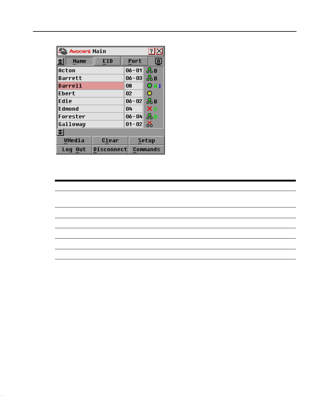
Use the Main dialog box to view, configure and control target devices in the DSR switching
system. You may view the target devices by name, port or by the unique Electronic ID (EID)
embedded in each DSRIQ module. You will see an OSCAR interface generated port list by default
when you first launch the OSCAR interface.
The Port column indicates the port to which a target device is connected.
To access the OSCAR interface Main dialog box:
Press
Print Screen to launch the OSCAR interface. The Main dialog box will appear.
®
graphical
Page 24
14 DSR Switch Installer/User Guide
Figure 3.1: Main Dialog Box
Table 3.1: Main Dialog Box Functions
Button Function
VMedia
Log Out Disconnect the KVM and user sessions.
Clear Clear all offline DSRIQ modules.
Disconnect Disconnect the KVM session.
Setup Access the Setup dialog box and configure the OSCAR interface.
Commands Access the Commands dialog box.
Set virtual media options and make virtual media connections. This option is only
available when a KVM session is in progress.
To manage a KVM session from the Main dialog box:
Click Clear to clear all offline DSRIQ modules.
-or-
Click Disconnect to disconnect a KVM session. If there is an associated Locked virtual media
session, it will be disconnected.
Page 25
Chapter 3: Local Port Operation 15
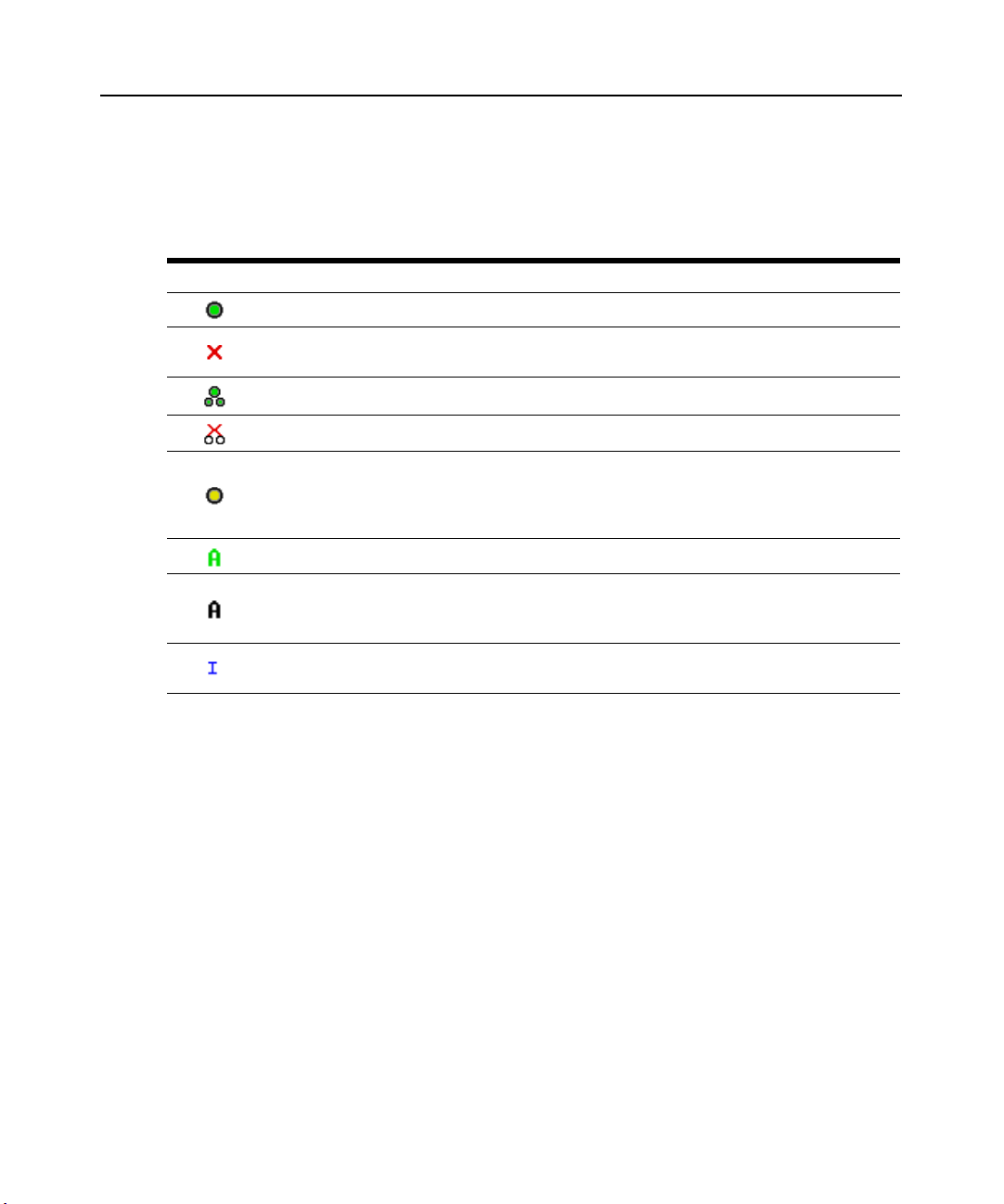
Viewing the status of your DSR switching system
The status of target devices in your system is indicated in the far right columns of the Main dialog
box. The following table describes the status symbols.
Table 3.2: OSCAR Interface Status Symbols
Symbol Description
(green circle) Server connected, powered up and the DSRIQ module is online.
Connected target device is powered down or is not operating properly and the DSRIQ module
is offline.
Connected switch is online.
Connected switch is offline or not operating properly.
(yellow circle) The designated DSRIQ module is being upgraded. When this symbol displays, do
not cycle power to the DSR switch or connected target devices and do not disconnect DSRIQ
modules. Doing so may render the module permanently inoperable and require the DSRIQ
module to be returned to the factory for repair.
(green letter) DSRIQ module is being accessed by the indicated user channel.
(black letter) DSRIQ module is blocked by the indicated user channel. For instance, in Figure
3.1, user B is viewing Forester, but is blocking access to Acton, Barrett and Edie which are
connected to the same DSRIQ module.
(blue letter) A remote virtual media connection is established to the server connected to the
indicated user channel.
Selecting target devices
Use the Main dialog box to select target devices. When you select a target device, the DSR switch
reconfigures the keyboard and mouse to the settings for the selected target device.
To select target devices:
Double-click the target device name, EID or port number.
-or-
If the display order of your list is by port (Port button is depressed), type the port number and
press
Enter.
-or-
If the display order of your list is by name or EID (Name or EID button is depressed), type the first
few letters of the name of the target device, or the EID number to establish it as unique and
press
Enter.
Page 26

16 DSR Switch Installer/User Guide
To select the previous target device:
Press
Print Screen and then Backspace. This key combination toggles you between the previous
and current connections.
To disconnect from a target device:
Press
Print Screen and then Alt+0 (zero). This leaves the user in a free state, with no target device
selected. The status flag on your desktop displays Free.
Soft switching
Soft switching is the ability to switch target devices using a hotkey sequence. You can soft switch
to a target device by pressing
number. If you have set a Screen Delay Time and you press the key sequences before that time has
elapsed, the OSCAR interface will not display.
To configure the OSCAR interface screen delay:
Print Screen and then typing the first few characters of its name or
1. Press
Print Screen to launch the OSCAR interface. The Main dialog box appears.
2. Click Setup - Menu. The Menu dialog box appears.
3. For Screen Delay Time, type the number of seconds of delay desired before the Main dialog
box is displayed after
Print Screen is pressed.
4. Click OK.
To soft switch to a target device:
1. Press
Print Screen. If the display order of the Main dialog is by port (Port button is depressed),
type the port number and press
Enter.
-orIf the display order of the Main dialog is by name (Name button is depressed), type the first
few letters of the name of the target device to establish it as unique and press
2. To switch back to the previous target device, press
Navigating the OSCAR Interface
This table describes how to navigate the OSCAR interface using the keyboard and mouse.
Table 3.3: OSCAR Interface Navigation Basics
This Keystroke Does This
Print Screen
F1 Opens the Help screen for the current dialog box.
Opens the OSCAR interface. Press Print Screen twice to send the Print Screen
keystroke to the currently selected DSRIQ module.
Enter.
Print Screen then Backspace.
Page 27

Table 3.3: OSCAR Interface Navigation Basics (Continued)
This Keystroke Does This
Closes the current dialog box without saving changes and returns to the previous
one. If the Main dialog box is displayed, pressing Escape closes the OSCAR
Escape
interface and displays a status flag if status flags are enabled. See
status flag
closes the pop-up box and returns to the current dialog box.
in this chapter for more information. In a message box, pressing Escape
Chapter 3: Local Port Operation 17
Controlling the
Alt
Alt+X Closes current dialog box and returns to previous one.
Alt+O Selects the
Enter
Single-click, Enter
Print Screen,
Backspace
Print Screen,
Alt+0 (zero)
Print Screen, Pause
Up/Down Arrows Moves the cursor from line to line in lists.
Right/Left Arrows
Page Up/Page Down Pages up and down through Name and Port lists and Help pages.
Home/End Moves the cursor to the top or bottom of a list.
Opens dialog boxes, selects or checks options and executes actions when used with
underlined or other designated letters.
OK
button, then returns to the previous dialog box.
Completes a switch operation in the Main dialog box and exits the
OSCAR interface.
In a text box, single-clicking an entry and pressing Enter selects the text for editing
and enables the Left and Right Arrow keys to move the cursor. Press Enter again
to quit the edit mode.
Toggles back to previous selection.
Immediately disengages user from a target device; no target device is selected.
Status flag displays
the numeric keypad.)
Immediately turns on Screen Saver mode and prevents access to that specific console,
if it is password protected.
Moves the cursor between columns. When editing a text box, these keys move the
cursor within the column.
Free
. (This only applies to the 0 (zero) on the keyboard and not
Backspace Erases characters in a text box.
Delete Deletes current selection in the Scan list or characters in a text box.
Shift-Del Deletes from the current selection to the end of the list when editing a Scan list.
Numbers Type from the keyboard or keypad.
Caps Lock Disabled. Use the Shift key to change case.
Backspace Erases characters in a text box.
Page 28
18 DSR Switch Installer/User Guide
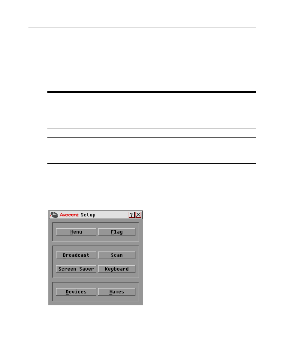
Configuring OSCAR Interface Menus
You can configure your DSR switching system from the Setup dialog box within the OSCAR
interface. Select the Names button when initially setting up your DSR switching system to identify
target devices by unique names. Select the other setup features to manage routine tasks for your
target devices from the OSCAR interface menu. Table 3.4 outlines the function accessed using
each of the buttons in the Setup dialog box (Figure 3.2).
Table 3.4: Setup Features to Configure the OSCAR Interface
Feature Purpose
Menu
Flag Change display, timing, color or location of the status flag.
Broadcast Simultaneously send mouse movements and keystrokes to multiple target devices.
Scan Set up a custom Scan pattern for up to 16 target devices.
Screen Saver Set passwords to protect or restrict access or enable the screen saver.
Keyboard Set the keyboard country code to send to Sun servers.
Devices Identify the appropriate number of ports on an attached cascade switch.
Names Identify target devices by unique names.
Change the Main dialog box list sorting option by toggling between numerically by port or EID
number and alphabetically by name. Change the Screen Delay Time before the OSCAR
interface displays after pressing Print Screen.
To access the OSCAR interface Setup dialog box:
1. Press
Print Screen to launch the OSCAR interface. The Main dialog box appears.
2. Click Setup. The Setup dialog box appears.
Figure 3.2: Setup Dialog Box
Page 29
Chapter 3: Local Port Operation 19
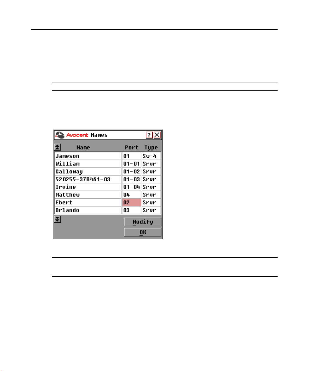
Assigning target device names
Use the Names dialog box to identify target devices by name rather than by port number. The
Names list is always sorted by port order. You can toggle between displaying the name or the EID
number of each DSRIQ module, so even if you move the target device to another port, the name
and configuration will be recognized by the switch.
NOTE: If a target device is turned off, its respective DSRIQ module will not appear in the Names list.
To access the OSCAR interface Names dialog box:
1. If the OSCAR interface is not open, press
Print Screen. The Main dialog box appears.
2. Click Setup - Names. The Names dialog box appears.
Figure 3.3: Names Dialog Box
NOTE: If new DSRIQ modules are discovered by the DSR switch, the on-screen list will be automatically
updated. The mouse cursor will change into an hourglass during the update. No mouse or keyboard input will be
accepted until the list update is complete.
Page 30
20 DSR Switch Installer/User Guide
To assign names to target devices:
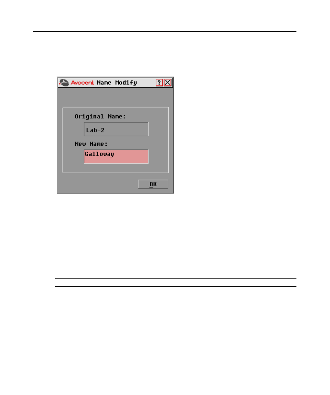
1. In the Names dialog box, select a target device name or port number and click Modify. The
Name Modify dialog box appears.
Figure 3.4: Name Modify Dialog Box
2. Type a name in the New Name box. Names of target devices may be up to 15 characters long. Legal
characters include: A-Z, a-z, 0-9, space and hyphen.
3. Click OK to transfer the new name to the Names dialog box. Your selection is not saved until
you click OK in the Names dialog box.
4. Repeat steps 1-3 for each target device in the system.
5. Click OK in the Names dialog box to save your changes.
-orClick X or press
NOTE: If a DSRIQ module has not been assigned a name, the EID is used as the default name.
Escape to exit the dialog box without saving changes.
To list target devices alphabetically by name:
Press
Alt+N or click Name in the Main dialog box.
Page 31

Chapter 3: Local Port Operation 21
Assigning device types
While the DSR switch automatically discovers attached cascade switches, you will need to specify
the number of ports on the cascade switch through the Devices dialog box. You will see an Sw-4,
Sw-6, Sw-8, Sw-16 or Sw-24 appear in the Type category for the cascade switch. Select the switch
from the list and the Modify button appears, allowing you to assign to the switch the appropriate
number of ports.
To access the OSCAR interface Devices dialog box:
1. If the OSCAR interface is not open, press
Print Screen. The Main dialog box will appear.
2. Click Setup - Devices. The Devices dialog box appears.
NOTE: The Modify button will only be available if a configurable switch is selected.
Figure 3.5: Devices Dialog Box
When the DSR switch discovers a cascade switch, you will notice the numbering format change
from a DSR port only to [DSR port]-[switch port] to accommodate each target device under
that switch.
For example, if a switch is connected to DSR port 6, each target device connected to it would be
numbered sequentially. The target device using DSR port 6, switch port 1 would be 06-01, the target
device using DSR port 6, switch port 2 would be 06-02 and so on.
To assign a device type:
1. In the Devices dialog box, select the desired port number.
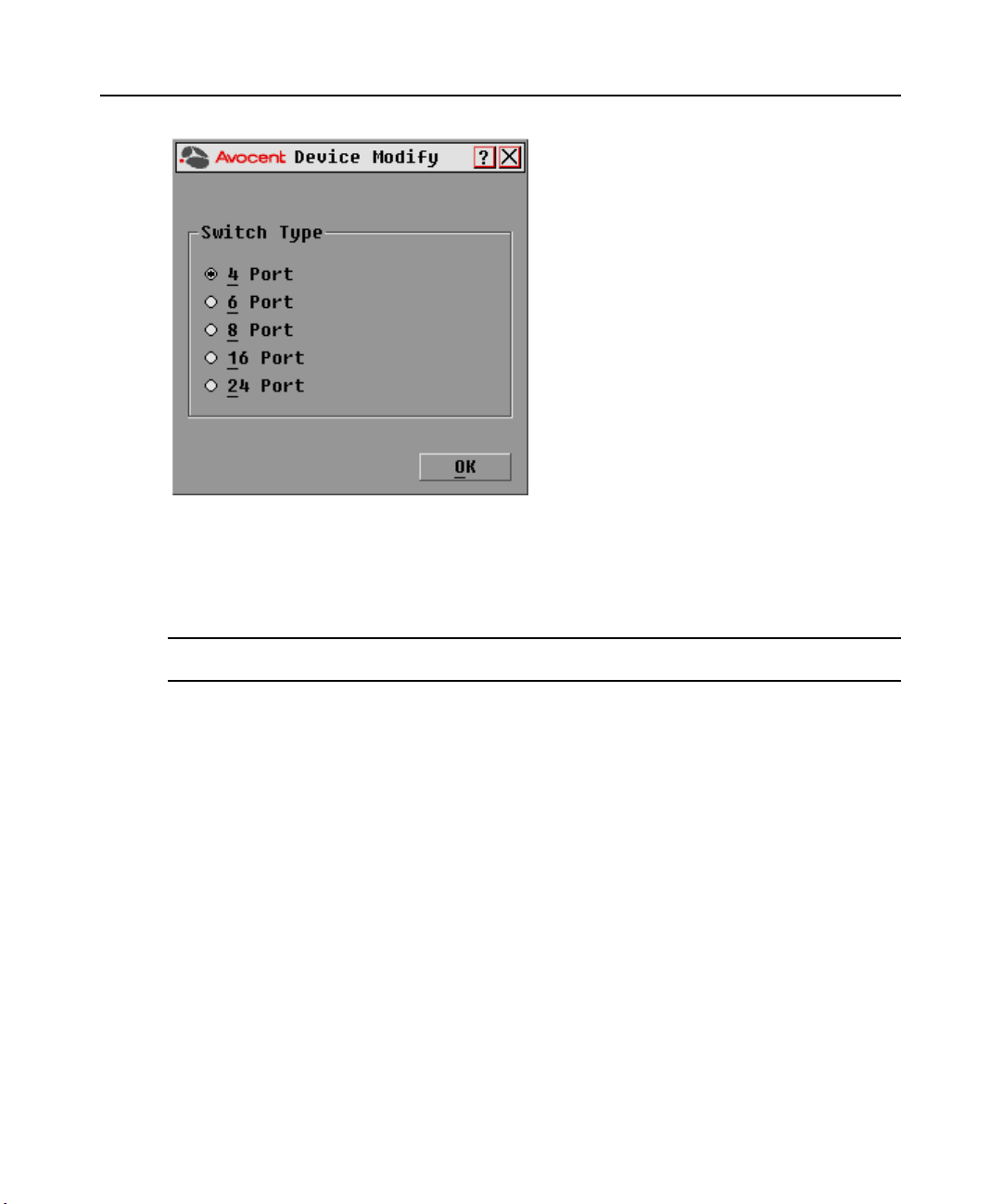
2. Click Modify. The Device Modify dialog box appears.
Page 32
22 DSR Switch Installer/User Guide
Figure 3.6: Device Modify Dialog Box
3. Choose the number of ports supported by your switch and click OK.
4. Repeat steps 1-3 for each port requiring a device type to be assigned.
5. Click OK in the Devices dialog box to save settings.
NOTE: Changes made in the Device Modify dialog box are not saved until you click
dialog box.
OK
in the Devices
Changing the display behavior
Use the Menu dialog box to change the display order of target devices and set a Screen Delay Time
for the OSCAR interface. The display order setting alters how target devices will display in several
dialog boxes, including Main, Devices and Broadcast.
To access the OSCAR interface Menu dialog box:
1. Press
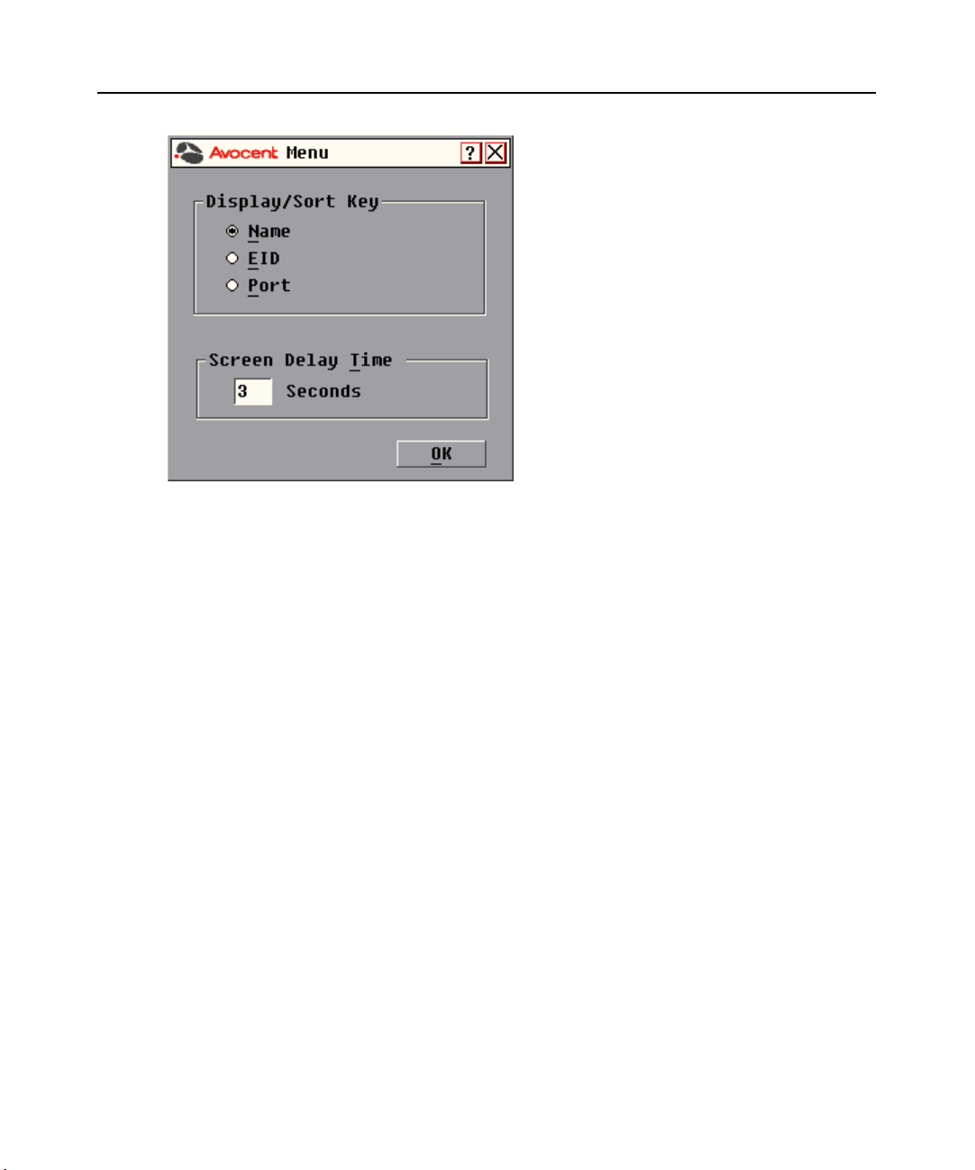
2. Click Setup - Menu in the Main dialog box. The Menu dialog box appears.
Print Screen to launch the OSCAR interface. The Main dialog box appears.
Page 33
Chapter 3: Local Port Operation 23
Figure 3.7: Menu Dialog Box
To choose the display order of target devices:
1. Select Name to display target devices alphabetically by name.
-orSelect EID to display target devices numerically by EID number.
-orSelect Port to display target devices numerically by port number.
2. Click OK.
Depending on the display method selected, the corresponding button will be depressed in the Main
dialog box.
To set a Screen Delay Time for the OSCAR interface:
1. Type in the number of seconds (0-9) to delay the OSCAR display after you press
Print Screen. Entering 0 will instantly launch the OSCAR interface with no delay.
2. Click OK.
Setting a Screen Delay Time allows you to complete a soft switch without the OSCAR interface
displaying. To perform a soft switch, see Soft switching in this chapter.
Page 34
24 DSR Switch Installer/User Guide
Controlling the status flag
The status flag displays on your desktop and shows the name or EID number of the selected target
device or the status of the selected port. Use the Flag dialog box to configure the flag to display by
target device name or EID number, or to change the flag color, opacity, display time and location
on the desktop.
Table 3.5: OSCAR Interface Status Flags
Flag Description
Flag type by name
Flag type by EID number
Flag indicating that the user has been disconnected from all systems
Flag indicating that Broadcast mode is enabled
To access the OSCAR interface Flag dialog box:
1. If the OSCAR interface is not open, press
Print Screen. The Main dialog box will appear.
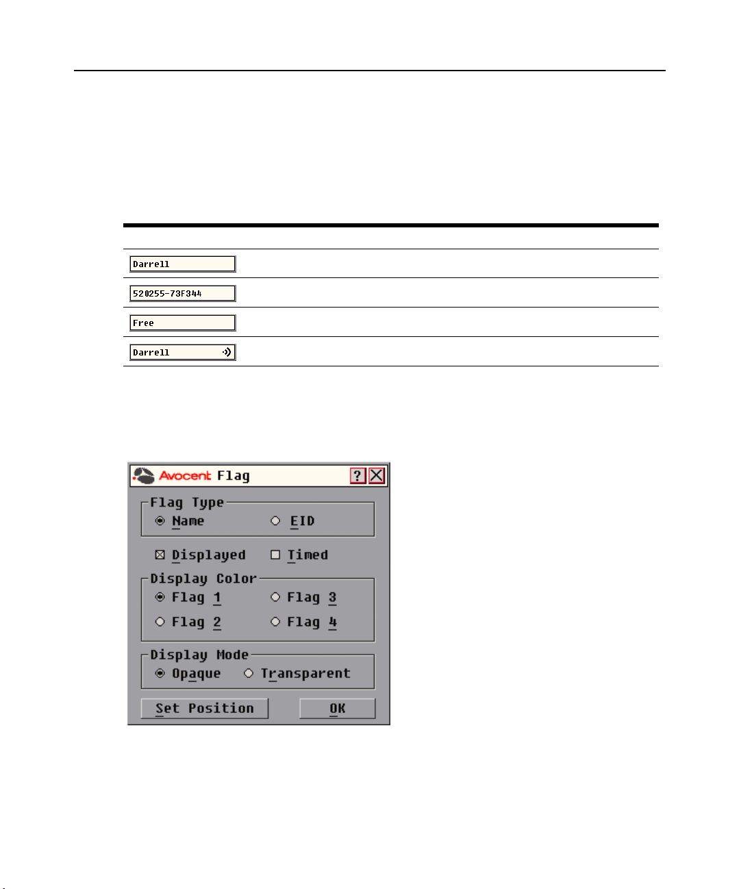
2. Click Setup - Flag. The Flag dialog box appears.
Figure 3.8: Flag Dialog Box
Page 35
Chapter 3: Local Port Operation 25
To determine how the status flag is displayed:
1. Select Name or EID to determine what information will be displayed.
2. Select Displayed to show the flag all the time or select Timed to display the flag for only five
seconds after switching.
3. Select a flag color under Display Color. The following flag colors are available:
• Flag 1 - Grey flag with black text
• Flag 2 - White flag with red text
• Flag 3 - White flag with blue text
• Flag 4 - White flag with violet text
4. In Display Mode, select Opaque for a solid color flag or select Transparent to see the desktop
through the flag.
5. To position the status flag on the desktop:
a. Click Set Position to gain access to the Position Flag screen.
Figure 3.9: Position Flag
b. Left-click on the title bar and drag to the desired location.
c. Right-click to return to the Flag dialog box.
NOTE: Changes made to the flag position are not saved until you click OK in the Flag dialog box.
6. Click OK to save settings.
-orClick X to exit without saving changes.
Broadcasting to target devices
The local user can simultaneously control multiple target devices in a system to ensure that all
selected target devices receive identical input. You can choose to broadcast keystrokes and/or
mouse movements independently.
NOTE: You can broadcast to as many as eight target devices at a time, one target device per port.
To access the OSCAR interface Broadcast dialog box:
1. If the OSCAR interface is not open, press
2. Click Setup - Broadcast. The Broadcast dialog box appears.
Print Screen. The Main dialog box will appear.
Page 36
26 DSR Switch Installer/User Guide
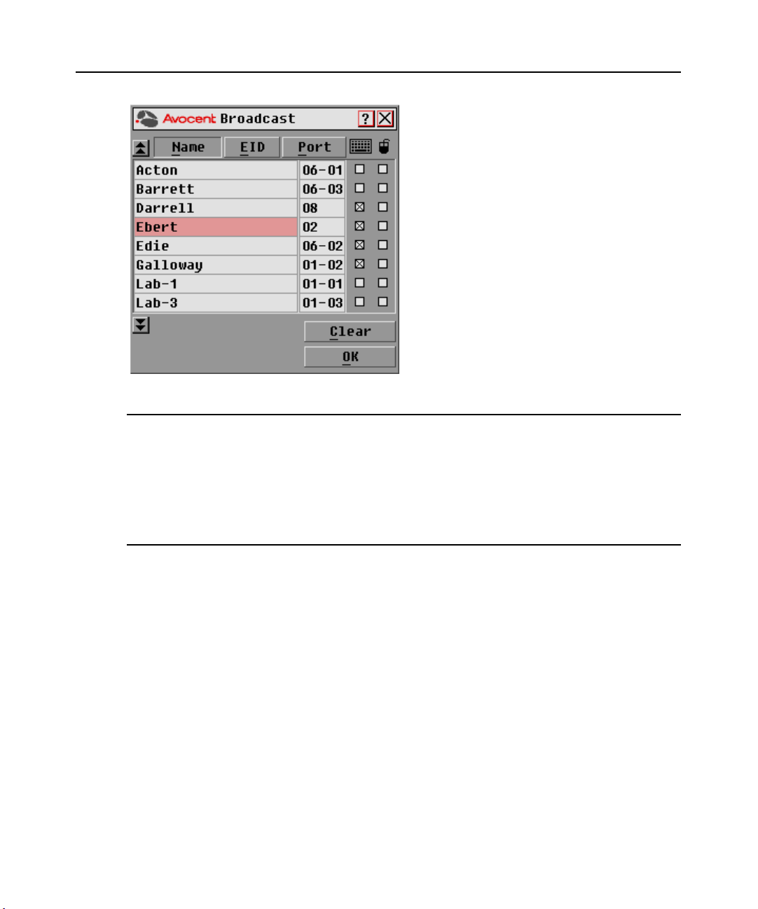
Figure 3.10: Broadcast Dialog Box
NOTE: Broadcasting Keystrokes - The keyboard state must be identical for all target devices receiving a
broadcast to interpret keystrokes identically. Specifically, the Caps Lock and Num Lock modes must be the
same on all keyboards. While the switch attempts to send keystrokes to the selected target devices
simultaneously, some target devices may inhibit and thereby delay the transmission.
Broadcasting Mouse Movements - For the mouse to work accurately, all systems must have identical mouse
drivers, desktops (such as identically placed icons) and video resolutions. In addition, the mouse must be in
exactly the same place on all screens. Because these conditions are extremely difficult to achieve, broadcasting
mouse movements to multiple systems may have unpredictable results.
To broadcast to selected target devices:
1. From the Broadcast dialog box, select the mouse and/or keyboard checkboxes for the target
devices that are to receive the Broadcast commands.
-orPress the
select the keyboard checkbox and/or
Up or Down Arrow keys to move the cursor to the target device. Then press Alt+K to
Alt+M to select the mouse checkbox. Repeat for
additional target devices.
2. Click OK to save the settings and return to the Setup dialog box. Click X or press
Escape to
return to the Main dialog box.
3. Click Commands. The Commands dialog box appears.
4. Click the Broadcast Enable checkbox to activate Broadcasting.
5. From the user station, type the information and/or perform the mouse movements you wish
to broadcast.
Page 37
Chapter 3: Local Port Operation 27
To turn Broadcasting off:
From the Commands dialog box, clear the Broadcast Enable checkbox.
Using Scan mode
In Scan mode, the DSR switch automatically scans from port to port (target device to target
device). You can scan up to eight target devices, specifying which ones to scan and the number of
seconds that each will display. The scanning order is determined by placement of the target device
in the list. The list is always shown in scanning order. You can, however, choose to display the
target device’s name or EID number by pressing the appropriate button.
NOTE: Scanning is only available to the local user.
To add target devices to the Scan list:
1. If the OSCAR interface is not open, press
Print Screen. The Main dialog box will appear.
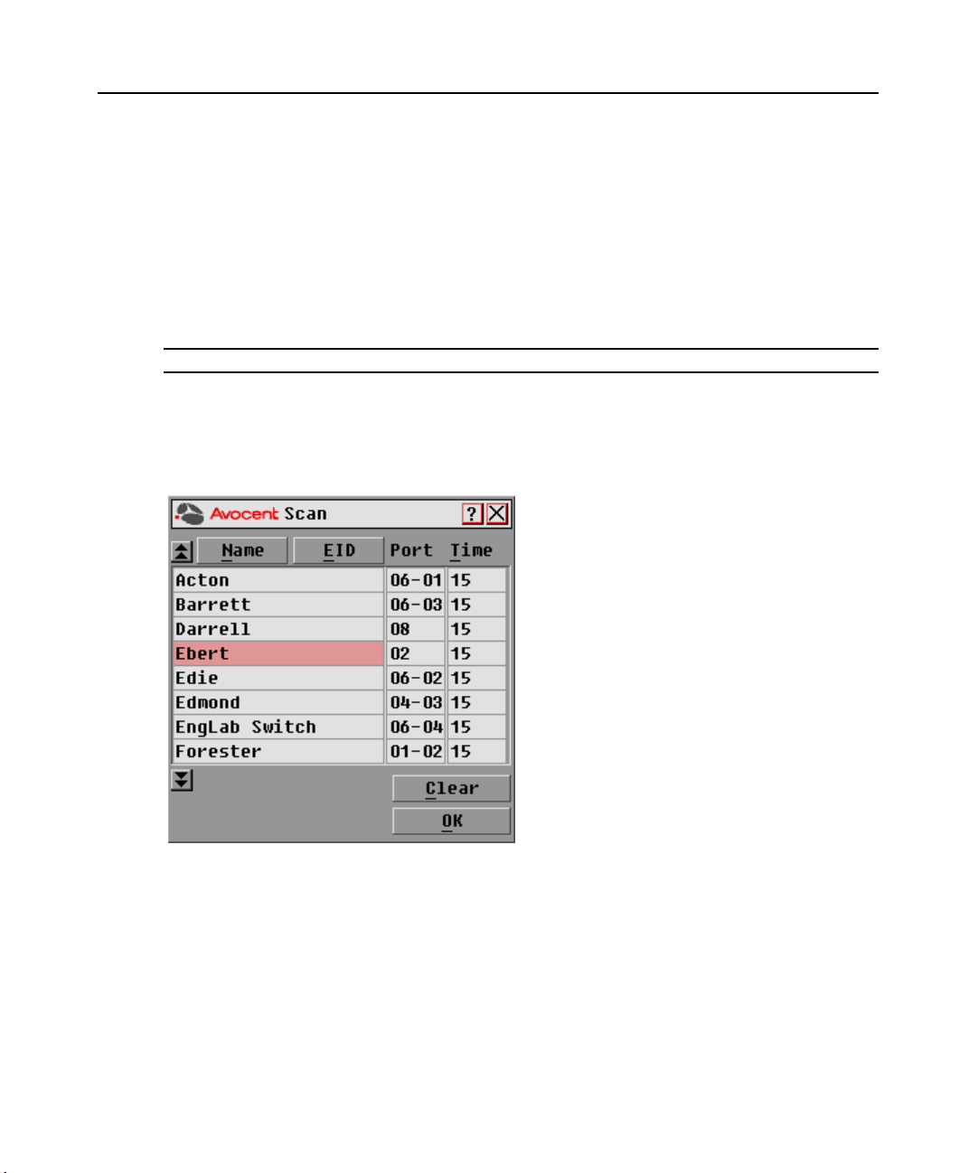
2. Click Setup - Scan. The Scan dialog box appears.
Figure 3.11: Scan Dialog Box
3. Determine the order within the list to add the target device. If there are no target devices in the
Scan list, your cursor will appear in a blank line at the top of the list.
-orTo add a target device to the end of the list, place your cursor in the last target device entry and
press the
Down Arrow key.
-orTo add a target device within an existing list, place your cursor in the line below where you want
to insert a new target device and press
Insert.
Page 38

28 DSR Switch Installer/User Guide
4. Type the first few characters of a target device name or port number to scan. The first matching
target device will appear in the line.
-orPress the following keyboard commands in the Name, Port or Time column to move through
the list of target devices available to scan.
a. Press
b. Press
c. Press
d. Press
Alt+Down Arrow to move the cursor down through the list of target devices.
Alt+Up Arrow to move the cursor up through the list of target devices.
Alt+Home to move the cursor to the first target device in the list.
Alt+End to move the cursor to the last target device in the list.
5. In the Time column, type the number of seconds (from 3-255) of desired time before the scan
moves to the next target device in the sequence.
6. Move the cursor to the next line or press
remaining target devices to be included in the scan pattern.
7. Click OK.
To remove a target device from the Scan list:
1. In the Scan dialog box, click the target device to be removed.
2. Press
Delete.
-orPress
Shift+Delete to remove the selected target device and all entries below it.
3. Click OK.
Down Arrow and repeat steps 2-5 for each of the
To start the Scan mode:
1. If the OSCAR interface is not open, press
Print Screen. The Main dialog box will appear.
2. Click Commands. The Commands dialog box appears.
Page 39
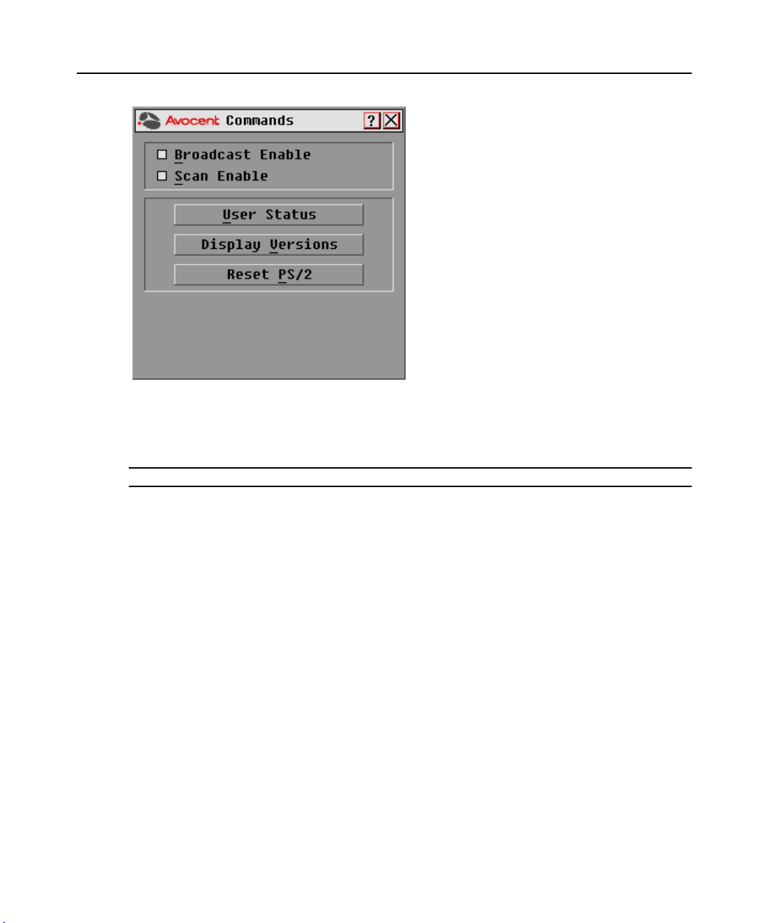
Figure 3.12: Commands Dialog Box
3. Select Scan Enable in the Commands dialog box.
4. Click X to close the Commands dialog box.
Chapter 3: Local Port Operation 29
NOTE: Scanning will begin as soon as the Scan Enable button is selected.
To cancel Scan mode:
Select a target device if the OSCAR interface is open.
-or-
Move the mouse or press any key on the keyboard if the OSCAR interface is not open. Scanning
will stop at the currently selected target device.
-or-
If the OSCAR interface is not open, press
Print Screen. The Main dialog box will appear.
a. Click Commands. The Commands dialog box appears.
b. Clear Scan Enable.
Page 40
30 DSR Switch Installer/User Guide
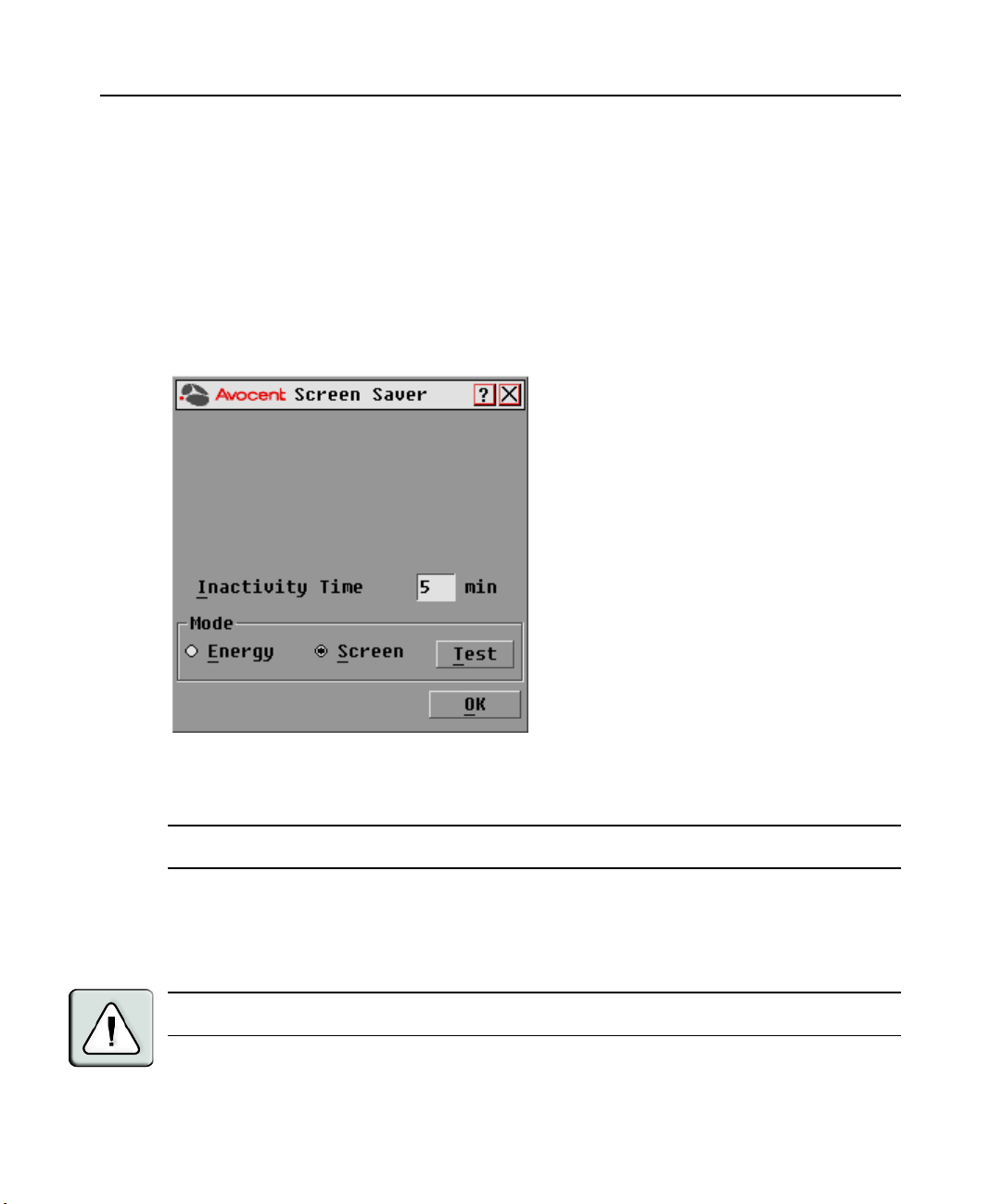
Setting local port Screen Saver options
Use the Screen Saver dialog box to manage the screen saver inactivity time and test the Screen
Saver mode on the local port. If security has been enabled in the DSView software, after the
specified Inactivity Time elapses, the local port locks and remains locked until you press any key or
move the mouse. You will then need to log in to continue.
To access the OSCAR interface Screen Saver dialog box:
1. If the OSCAR interface is not open, press
Print Screen. The Main dialog box will appear.
2. Click Setup - Screen Saver. The Screen Saver dialog box appears.
Figure 3.13: Screen Saver Dialog Box
To set the Screen Saver options:
NOTE: The Screen Saver password is set within the DSView software. For more information, see the DSView
Installer/User Guide.
1. Type the number of minutes for Inactivity Time (from 1-99) to delay activation of password
protection and the screen saver feature.
2. For Mode, select Energy if your monitor is E
NERGY STAR
®
compliant; otherwise
select Screen.
CAUTION: Monitor damage can result from the use of Energy mode with monitors not compliant with
ENERGY STAR®.
Page 41

Chapter 3: Local Port Operation 31
3. (Optional) Click Te st to activate the screen saver test which lasts 10 seconds then returns you
to the Security dialog box.
4. Click OK.
To exit Screen Saver mode and log in to the local port:
1. Press any key or move the mouse.
2. If Screen Saver security was turned on in the DSView software, you will see a login screen.
Enter your username and password and then click OK. If you do not know your username and
password, see the DSView Server software administrator.
3. The Main dialog box appears and any previous target device connection will be restored.
To immediately turn on the screen saver:
Press
Print Screen, then press Pause. This command only works when the user is connected to a
target device.
Setting the keyboard country code
NOTE: Using a keyboard code that supports a language different from that of your DSR switch firmware will
cause incorrect keyboard mapping.
Sun servers may use keyboard mappings for non-US keyboards. By default, the DSR switch sends
the US keyboard country code to Sun and USB modules attached to target devices and the code is
applied to the target devices when they are powered up or rebooted. Codes are then stored in the
DSRIQ module.
Issues may arise when you use the US keyboard country code with a keyboard of another country.
For example, the
keyboard. Sun servers will interpret pressing the
when the US keyboard country code is used.
The Keyboard dialog box enables you to send a different keyboard country code than the default
US setting. The specified country code is sent to all target devices attached to the DSR switches
when they are powered up or rebooted and the new code is stored in the DSRIQ module.
Z key on a US keyboard is in the same location as the Y key on a German
Y key on a German keyboard as pressing the Z key
NOTE: If a DSRIQ module is moved to a different target device, the keyboard country code will need to be reset.
See Appendix F for information on emulating certain Sun keys using a PS/2 keyboard and special
considerations for Japanese and Korean Sun USB keyboards.
NOTE: Only local users can view or change keyboard country code settings.
Page 42

32 DSR Switch Installer/User Guide
To set the keyboard country code for Sun servers:
1. If the OSCAR interface is not open, press
Print Screen. The Main dialog box will appear.
2. Click Setup - Keyboard. The Keyboard dialog box appears.
Figure 3.14: Keyboard Dialog Box
3. Select a country code and click OK.
4. Reboot the Sun servers. After rebooting, each Sun server will request the country code setting
stored in the DSRIQ module.
NOTE: If you wish to reboot the target devices by power-cycling them, you must wait 90 seconds before
rebooting. A soft reboot may be performed without waiting 90 seconds.
Page 43

Setting Virtual Media Options
You can determine the behavior of the DSR switch during a virtual media session using the options
provided in the Virtual Media dialog box. Table 3.6 outlines the options that can be set for virtual
media sessions.
Table 3.6: Virtual Media Options
Function Purpose
Appliance
Chapter 3: Local Port Operation 33
Locked
Select Local
Mapping Options
Reserve
CD ROM
Mass Storage
Write Access
Synchronizes the KVM and virtual media sessions so that when a user disconnects a
KVM connection, the virtual media connection to that server is also disconnected. A
local user attempting to switch to a different server is also disconnected.
Ensures that a virtual media connection can only be accessed with your username
and that no other user can create a KVM connection to that server. When the
associated KVM session is disconnected, the virtual media session may be
disconnected according to the Locked setting in the Virtual Media dialog box.
Allows virtual media sessions to the first detected CD-ROM drive. Enable this
checkbox to establish a virtual media CD-ROM connection to a server. Disable to
end a virtual media CD-ROM connection to a server.
Allows virtual media sessions to the first detected mass storage drive. Enable this
checkbox to establish a virtual media mass storage connection to a server. Disable
to end a virtual media mass storage connection to a server.
Allows a target server to write data to the virtual media during a virtual media
session. Read access is always allowed during a virtual media session.
To set virtual media options:
1. If the OSCAR interface is not open, press
Print Screen. The Main dialog box appears.
2. Click Setup - VM. The Virtual Media dialog box appears.
Page 44

34 DSR Switch Installer/User Guide
Figure 3.15: Virtual Media Dialog Box
3. Click to enable or disable each of the options. For information about individual settings, see
Table 3.6.
4. Click OK to accept the options you have selected and return to the Setup dialog box.
Page 45

Chapter 3: Local Port Operation 35
Managing Server Tasks Using the OSCAR Interface
From the OSCAR interface Commands dialog box, you can manage your DSR switching system
and user connections, enable the Scan and Broadcast modes and update your firmware.
Table 3.7: Commands to Manage Routine Tasks for Your Target Device(s)
Feature Purpose
Broadcast Enable
Scan Enable
User Status View and disconnect users.
Begin broadcasting to your target devices. Configure a target device list for
broadcasting under the Setup dialog box.
Begin scanning your target devices. Set up a target device list for scanning in the
Setup dialog box.
Display Versions
Reset PS/2 Re-establish operation of PS/2 keyboard and mouse.
View version information for the DSR switch as well as view and upgrade firmware
for individual DSRIQ modules.
To access the OSCAR interface Commands dialog box:
1. Press
Print Screen to launch the OSCAR interface. The Main dialog box appears.
2. Click Commands. The Commands dialog box appears.
Figure 3.16: Commands Dialog Box
Page 46

36 DSR Switch Installer/User Guide
Viewing and disconnecting user connections
You can view and disconnect users through the User Status dialog box. The username (U) will
always be displayed; however, you can display either the target device name or EID number to
which a user is connected. If there is no user currently connected to a channel, the user field will be
blank and the Server Name field will display Free.
To view current user connections:
1. If the OSCAR interface is not open, press
Print Screen. The Main dialog box will appear.
2. Click Commands - User Status. The User Status dialog box appears.
Figure 3.17: User Status Dialog Box
To disconnect a user:
1. If the OSCAR interface is not open, press
Print Screen. The Main dialog box will appear.
2. Click Commands - User Status. The User Status dialog box appears.
3. Click the letter corresponding to the user to disconnect. The Disconnect dialog box will appear.
Page 47

Chapter 3: Local Port Operation 37
Figure 3.18: Disconnect Dialog Box
4. Click OK to disconnect the user and return to the User Status dialog box.
-orClick X or press
Escape to exit the dialog box without disconnecting a user.
NOTE: If the User Status list has changed since it was last displayed, the mouse cursor will turn into an
hourglass as the list is automatically updated. No mouse or keyboard input will be accepted until the list update
is complete.
Resetting your PS/2 keyboard and mouse
NOTE: This function is for Microsoft Windows-based computers only. Resetting the PS/2 on a target device
running any other operating system may require that you reboot that target device.
If your PS/2 keyboard or mouse locks up, you may be able to re-establish operation of these peripherals
by issuing a Reset command. The Reset command sends a hot-plug sequence to the target device which
causes the mouse and keyboard settings to be sent to the D SR switch. With communication reestablished between the target device and the DSR switch, functionality is restored to the user.
To reset the PS/2 mouse and keyboard values:
1. If the OSCAR interface is not open, press
Print Screen. The Main dialog box will appear.
Page 48
38 DSR Switch Installer/User Guide
2. Click Commands - Reset PS/2. A message box displays requesting that you confirm the reset.
Click OK.
a. A message appears indicating that the mouse and keyboard have been reset.
b. Click X to close the message box.
-orClick X or press
Escape to exit without sending a Reset command to the PS/2 mouse
and keyboard.
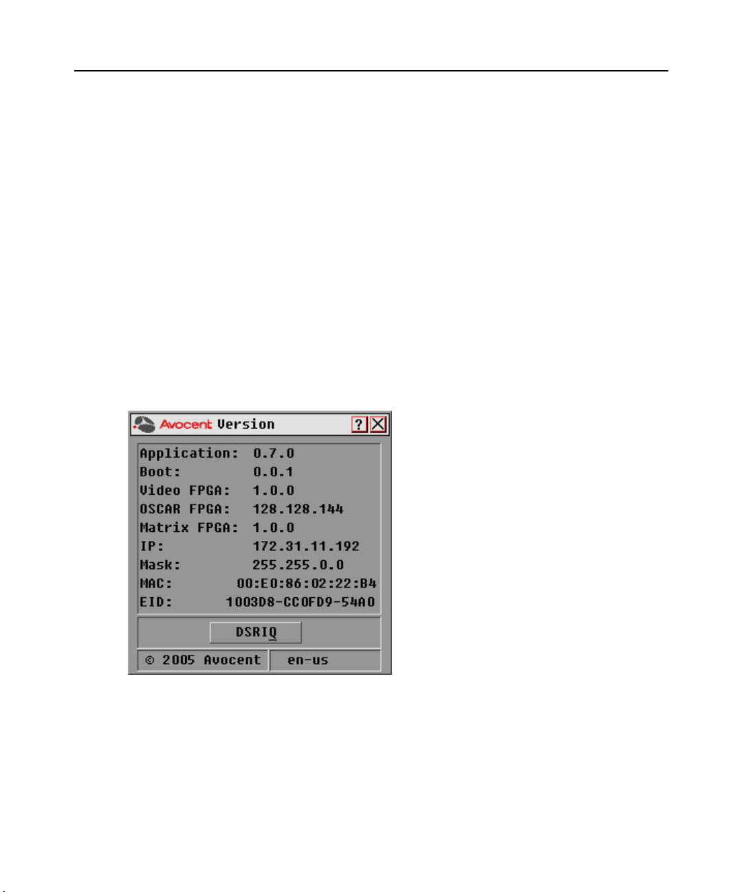
Displaying version information
The OSCAR interface enables you to display the version number of the switch firmware and any
auxiliary devices connected to the switch. This information facilitates system troubleshooting and
support. For optimum performance, keep your firmware current.
To display version information:
1. If the OSCAR interface is not open, press
Print Screen. The Main dialog box will appear.
2. Click Commands - Display Versions. The Version dialog box appears. The top half of the box
lists the subsystem versions in the DSR switch.
Figure 3.19: Version Dialog Box
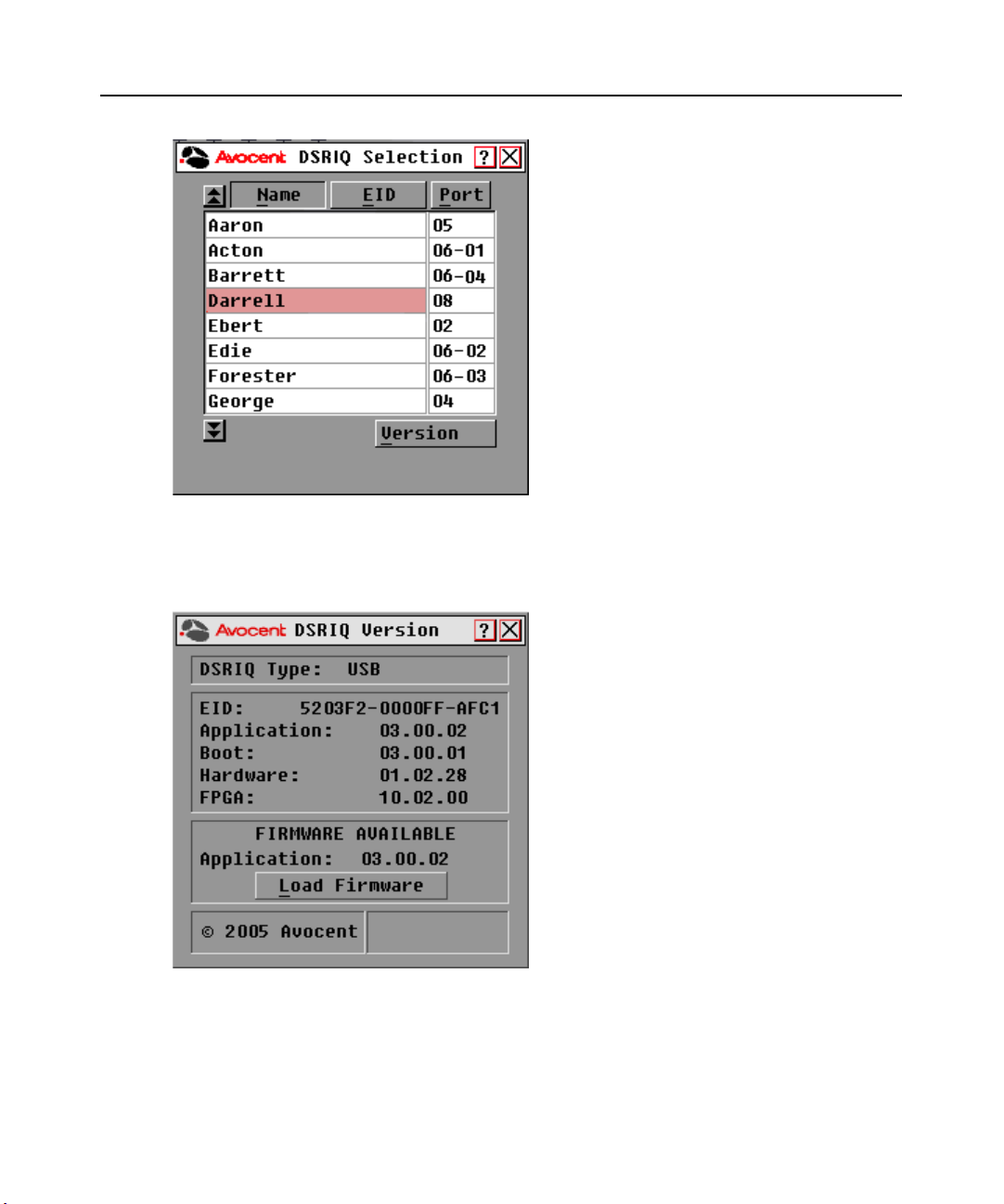
3. Click DSRIQ to view individual DSRIQ module version information. The DSRIQ Selection
dialog box appears.
Page 49
Chapter 3: Local Port Operation 39
Figure 3.20: DSRIQ Selection Dialog Box
4. Select a DSRIQ module to view and click the Ver si on button. The DSRIQ Version dialog box
appears. For more information on loading firmware, see Appendix A.
Figure 3.21: DSRIQ Version Dialog Box
5. Click X to close the DSRIQ Version dialog box.
Page 50

40 DSR Switch Installer/User Guide
Page 51

CHAPTER
Terminal Operations
4
The Console Menu
Each DSR switch may be configured at the appliance level through the Console menu interface
accessed through the SETUP port on the back of the switch. All terminal commands are accessed
through a terminal or PC running terminal emulation software.
NOTE: This is NOT the recommended method for setting options for the DSR switch. The preferred method is to
make all configuration settings in the DSView Server software. See the DSView Installer/User Guide for
more information.
Network Configuration
41
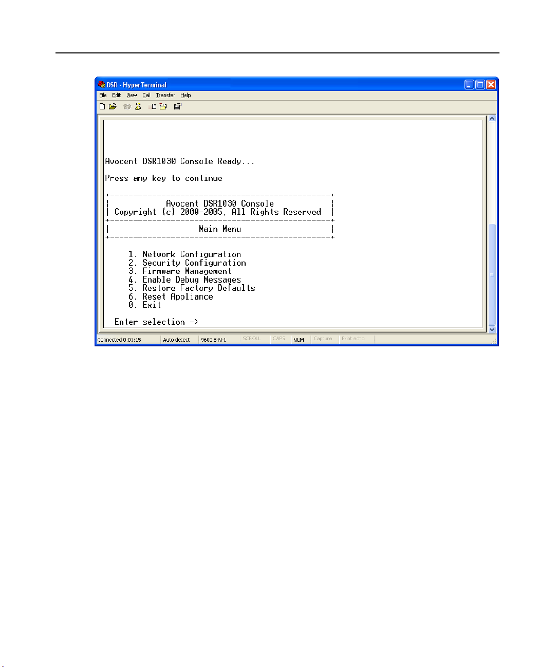
To configure network settings using the Console menu:
1. When you power up your DSR switch, the switch initializes for approximately one minute.
After it completes initialization, press any key on the terminal or on the PC running the
terminal emulation software to access the Console menu interface. Actually, the terminal may
be connected at any time, even when the switch is already powered.
Page 52
42 DSR Switch Installer/User Guide
Figure 4.1: Console Main Menu
2. The Console Main menu displays. Type 1 and press Enter for the Network Configuration
option. The Network Configuration menu displays.
Page 53

Chapter 4: Terminal Operations 43
Figure 4.2: Network Configuration Menu
3. Type 1 and press Enter to set your network speed. When possible, you should set your
connection manually without relying on the auto negotiate feature. After you press
Enter, you
will be returned to the Network Configuration menu.
4. Type
2 and press Enter to specify whether you are using a static or Dynamic Host
Configuration Protocol (DHCP) address. A static IP address may be used to provide a userdefined IP address, netmask and default gateway for the DSR switch. Avocent recommends
using a static IP address for ease of configuration. DHCP is a protocol that automates the
configuration of TCP/IP-enabled computers. When DHCP is selected, the IP Address,
Netmask and Default Gateway settings are automatically assigned to the DSR switch and may
not be modified by a DS user. If you are using the DHCP option, please configure your DHCP
server to provide an IP address to the DSR switch and then skip step 5.
5. Select the remaining options from the Network Configuration menu to finish the
configuration of your DSR switch with an IP address, netmask, default gateway and
ping response.
6. Type
0 (zero) and press Enter to return to the Console Main menu.
Page 54

44 DSR Switch Installer/User Guide
Other Console Main Menu Options
Besides the Network Configuration option, the Console Main menu of the DSR switch features the
following menu items: Security Configuration, Firmware Management, Enable Debug Messages,
Restore Factory Defaults, Reset Appliance and Exit. Each is discussed below.
Security Configuration
The DSR switch contains an internal database that may be used by the DSR Remote Operations
software, the local port or the CONSOLE port if the DSView software server is unavailable.
The Security Configuration menu contains the following options:
• Local User Accounts: Add, edit or delete users to/from the DSR switch database.
• Console Password: Enable or disable using security for the console (access requires an
Admin account).
• Reset Certificates: Reset the certificate used by the DSView software system.
• Secure Mode: Enable or disable the DSView software Secure mode.
Local User Accounts
NOTE: When you use the options to add, edit or delete a user, a list of existing users will appear. You may enter
N to display the next page of users in the database or enter P to go back to the previous page of users.
To add a user to the DSR switch database:
1. Type
2. Type
2 and press Enter to access the Security Configuration menu option.
1 and press Enter to access the Local User Accounts menu option. A list of users already
within the database will appear.
3. Type
4. You will be prompted to enter the username to add. Type a username and press
5. You will be prompted to type a password for the user. Type a password and press
6. You will be prompted to re-type the password. Type the password again and press
7. Enter
A.
Enter.
Enter.
Enter.
0 (zero) to exit.
To rename a user in the DSR switch database:
1. From the Console Main menu, type
2 and press Enter to access the Security Configuration
menu option.
2. Type
1 and press Enter to access the Local User Accounts menu option. A list of users already
within the database will appear.
3. Type
E.
4. You will be prompted to enter the number of the user you wish to rename. Type the user’s
number then press
5. Type a new username and press
Enter.
Enter.
Page 55

Chapter 4: Terminal Operations 45
6. Enter the password for the user, then re-enter the password to confirm it.
7. Enter
0 (zero) to exit.
To remove a user from the DSR switch database:
1. From the Console Main menu, type
2 and press Enter to access the Security Configuration
menu option.
2. Type
1 and press Enter to access the Local User Accounts menu option. A list of users already
within the database will appear.
3. Type
D.
4. You will be prompted to enter the number of the user you wish to delete. Type the user’s
number then press
5. You will be prompted to confirm deletion of the user from the DSR switch database. Type
and press
6. Enter
Enter to remove the user.
0 (zero) to exit.
Enter.
Y
Console Password
If this is enabled, access to the switch’s Console Main menu will require the user to log in.
Reset Certificates
This menu option enables you to clear the certificate sent by the DSView software to the
DSR switch.
When a DSR switch is added to a server running DSView software, a certificate is downloaded
from that server to the DSR switch automatically. That certificate is replicated across all servers
running DSView software operating in a predefined system. Thereafter, any of the servers in that
system will be able to communicate with the DSR switch.
If the server running DSView software cannot contact the DSR switch to add the
certificate, an error message is displayed and the DSR switch is not added to the database.
Secure Mode
The DSR switch operates in one of two modes: Security disabled or Security enabled.
In Security disabled mode, the DSR switch allows any server running DSView software to
communicate with it.
In Security enabled mode, an initial server running DSView software is allowed to download a
certificate to the switch. If that server is part of a system that replicates certificates, it will pass
the certificate to the other servers in that certificate replication system. Thereafter, all servers in
that system will be allowed to access the DSR switch. All servers that are not part of that system
will be locked out.
When the DSR switch is removed from the DSView software database, the certificate is
removed from the DSR switch. This enables you to move the DSR switch from one certificate
Page 56

46 DSR Switch Installer/User Guide
replication system to another. The certificate can also be removed using the Console menu
accessed via the SETUP port on the DSR switch. See the Reset Certificates section.
See the DSView Installer/User Guide for more information on software security.
Firmware Management
This menu contains the FLASH Download selection. For more information, see Appendix A.
Enable Debug Messages
This menu option turns on console status messages. Because this can significantly reduce
performance, you should only enable debug messages when instructed to do so by Avocent
Technical Support. When you are finished viewing the messages, press any key to exit this mode.
Restore Factory Defaults
This menu option will restore all switch options to the default settings.
Reset Appliance
This menu option allows you to execute a soft reset of the DSR switch.
Exit
This menu selection will return you to the ready prompt. If the Console menu interface password is
enabled, you must exit the Console Main menu so that the next user will be prompted with the
Username and Password login screen.
Page 57

APPENDICES
Appendix A: FLASH Upgrades
The DSR switch FLASH upgrade feature allows you to update your appliance with the latest
firmware available. This update can be performed using the DSView software or using a Trivial
File Transfer Protocol (TFTP) server.
After the FLASH memory is reprogrammed with the upgrade, the DSR switch performs a soft
reset, which terminates all DSRIQ module sessions. A target device experiencing a DSRIQ module
firmware update may not display, or may display as disconnected. The target device will appear
normally when the FLASH update is completed.
NOTE: During an upgrade, the DSRIQ module status indicator in the OSCAR interface Main dialog box is yellow.
CAUTION: Disconnecting a DSRIQ module during a firmware update or cycling power to the target device will
render the module inoperable and require the DSRIQ module to be returned to the factory for repair.
To upgrade the DSR switch firmware using the DSView software:
The preferred method for updating the firmware is to use the DSView software. See the DSView
Installer/User Guide for detailed instructions.
To upgrade the DSR switch firmware using the Console menu interface:
47
NOTE: If you do not have a TFTP server, you can find several shareware and freeware programs on the Internet
that you can download and install.
1. Visit http://www.avocent.com/support and download the latest FLASH firmware from
Avocent. Save the FLASH upgrade file to the appropriate directory on the TFTP server.
2. Connect a terminal or PC running terminal emulation software (such as HyperTerminal) to the
SETUP port on the back panel of the DSR switch using the supplied null modem cable. The
terminal should be set to 9600 bps, 8 bits, 1 stop bit, no parity and no flow control.
3. If the DSR switch is not on, turn it on now. After approximately one minute, press any key to
access the Console Main menu.
4. The Console Main menu displays. Select the Firmware Management option.
NOTE: The current version of your firmware will be displayed on the Firmware Management menu.
5. Type 1 and press Enter to access FLASH Download.
6. Type the IP address of your TFTP server and press
Enter.
7. Enter the name of the file that you downloaded from the Avocent web site.
8. Confirm the TFTP download by typing a
y or yes and pressing Enter.
9. The DSR switch will verify that the file you downloaded is valid. Next, you will be prompted to
confirm the upgrade. Type a
y or yes and press Enter to confirm.
Page 58

48 DSR Switch Installer/User Guide
10. The DSR switch will begin the FLASH upgrade process. On-screen indicators will display the
upgrade progress. When the upload is complete, the DSR switch will reset and upgrade the
internal subsystems.
11. Once the upgrade is complete, a verification message will appear on-screen.
Page 59

Appendices 49
Appendix B: Using DSView Software Over a Modem Connection
An external modem may be attached to the DSR switch. This modem may be used to access the
switch when an Ethernet connection is not available.
A modem/PPP dial-up connection must be established before the remote operation is enabled. The
dial-up connection options should be set to 115,200 bps, 8 bits, 1 stop bit, no parity and enabled
hardware flow control.
Before you begin
The following actions should be performed before using the DSR Remote Operations software:
• Ensure that the DSR switch is configured. See Chapter 2 for more information.
• Ensure that DSR switch users have been added to the DSR switch internal database. If the
DSView Server software is not available, the switch database is used for authentication. If
neither are available, authentication cannot be performed for the DSR switch. See Chapter 4
for more information.
• Ensure that an external modem is attached to the DSR switch MODEM port. The modem
should have auto-answer turned off (typically a modem’s default setting).
• Ensure that your client PC contains dial-up software and that the software is configured
properly. See your operating system documentation for more information.
Establishing a DSR Remote Operations software connection
This is explained in detail in the DSView Installer/User Guide.
Page 60

50 DSR Switch Installer/User Guide
Appendix C: Using DSRIQ-SRL Modules
The DSRIQ-SRL module is a serial-to-VGA converter which permits VT100-capable devices to be
viewed from the DSR switch local port or by using the DSView software. The actual serial data is
not accessed, but is merely displayed. All serial data coming from the target device is displayed in a
VT100 window, placed into a video buffer and sent to the DSR switch as though it came from a
VGA target. Likewise, keystrokes entered on a keyboard are sent to the attached device as though
they were typed upon a VT100 terminal.
DSRIQ-SRL module modes
The following modes can be accessed from the DSRIQ-SRL module:
• On-Line: This mode enables you to send and receive serial data.
• Configuration: This mode enables you to specify DSR switch communication parameters, the
appearance of the Terminal Applications menu and key combinations for specific actions
and macros.
• History: This mode enables you to review serial data.
Configuring the DSRIQ-SRL module
NOTE: The DSRIQ-SRL module is a DCE device and only supports VT100 terminal emulation.
Pressing Ctrl-F8 will activate the Configuration screen of the DSRIQ module’s Terminal
Applications menu, which enables you to configure your DSRIQ-SRL module.
NOTE: When any Terminal Applications menu is active, pressing Enter saves changes and returns you to the
previous screen. Pressing Escape returns you to the previous screen without saving changes.
Within the Terminal Applications menu’s Configuration screen, you can modify the
following options:
• Baud Rate: This option allows you to specify the serial port communications speed. Available
options are 300, 1200, 2400, 9600, 19,200, 34,800, 57,600 or 115,200 bps. The default value
is 9600.
• Parity: This option allows you to specify the serial port’s communications parity. Available
options are EVEN, ODD or NONE. The default value is NONE.
• Flow Control: This option allows you to specify the type of serial flow control. Available
options are NONE, XOn/XOff (software) and RTS/CTS (hardware). The default value
is NONE. If you select a bps rate of 115,200, the only available flow control is
RTS/CTS (hardware).
• DSR/CD Mode: This option allows you to control how the DSR switch and CD lines operate.
Available options are Always on and Toggle. When in Toggle mode, DSR and CD lines are
turned off for one-half second and then turned on each time a module is selected or deselected.
The default value is Always on.
Page 61

Appendices 51
• Enter Sends: This option enables you to specify the keys that are transmitted when Enter is
pressed. Available options are <CR> (Enter), which moves the cursor to the left side of the
screen, or <CR><LF> (Enter-Linefeed), which moves the cursor to the left side of the screen
and down one line.
• Received: This option enables you to specify how the module translates a received
Enter
character. Available options are <CR> (Enter) or <CR><LF> (Enter-Linefeed).
• Background: This option changes the screen’s background color. The currently-selected color
displays in the option line as it is changed. Available colors are Black, Light Grey, Yellow,
Green, Teal, Cyan, Blue, Dark Blue, Purple, Pink, Orange, Red, Maroon and Brown. The
default color is Black. This value cannot be identical to the Normal Text or Bold Text value.
• Normal Text: This option changes the screen’s normal text color. The currently-selected
color displays in the option line as it is changed. Available colors are Grey, Light Grey,
Yellow, Green, Teal, Cyan, Blue, Dark Blue, Purple, Pink, Orange, Red, Maroon and Brown.
The default color is Grey. This value cannot be identical to the Bold Text or
Background value.
• Bold Text: This option changes the screen’s bold text color. The currently-selected color
displays in the option line as it is changed. Available colors are White, Yellow, Green, Teal,
Cyan, Blue, Dark Blue, Purple, Pink, Orange, Red, Maroon, Brown and Light Grey. The
default color is White. This value cannot be identical to the Normal Text or Background value.
• Screen Size: This option allows you to specify the screen’s text width size. Available values
are widths of 80 columns or 132 columns. The length for both widths is 26 lines.
The following Terminal Application menu’s Configuration screen options enable you to define the
function keys that will perform a selected action. To specify a new function key, press and hold the
Ctrl key, then press the function key that you want to associate with the action. For example, if you
want to change the Configuration (Config) Key Sequences option from <CTRL-F8> to
<CTRL-F7>, press and hold the
Ctrl key and then press F7.
• Config Key Sequences: This option allows you to define the key combination that causes the
Terminal Application menu’s Configuration screen to appear. The default key sequence is
F8
.
Ctrl-
• On-Line Key Sequence: This option allows you to define the key sequence that displays the
On-Line mode. The default key sequence is
Ctrl-F10.
• Help Key Sequence: This option allows you to define the key combination that displays the
Help System screen. The default key sequence is
Ctrl-F1.
• History Key Sequence: This option allows you to define the key combination that enables
History mode. The default key sequence is
Ctrl-F9.
• Clear History Key Sequence: This option allows you to define the key combination that clears
the history buffer while in History mode. The default key sequence is
Ctrl-F11.
• Break Key Sequence: This option allows you to configure the key combination that generates a
break condition. The default key sequence is
Alt-B.
Page 62

52 DSR Switch Installer/User Guide
To configure a DSRIQ-SRL module:
1. Press
2. Select a parameter to change. You can navigate the Configuration Screen using the
3. Modify the selected value using the
Ctrl-F8. The Configuration Screen will appear.
and
Down Arrow keys.
Left Arrow and Right Arrow keys.
Up Arrow
4. Repeat steps 2 and 3 to modify additional values.
5. Press
Enter to save your changes and exit the Configuration Screen.
-orPress
Escape to exit the Configuration Screen without saving the changes.
Creating a DSRIQ-SRL module macro
Pressing the Page Down key when the Terminal Applications menu’s Configuration screen is
displayed will provide access to the Macro Configuration screen. The DSRIQ-SRL module can be
configured with up to 10 macros. Each macro can be up to 128 characters in length.
To create a macro:
1. Select the DSRIQ-SRL module you wish to configure and press
Terminal Applications menu’s Configuration screen.
2. When the Terminal Applications menu appears, press
Page Down to view the Macro Configuration
screen. The Macro Configuration screen shows the 10 available macros and the associated key
sequences, if any, for each.
3. Using the
Up Arrow and Down Arrow keys, scroll to an available macro number and highlight
the listed keystroke sequence. Type the new macro keystroke sequence over the default. Any
combination of
Ctrl or Alt and a single key may be used. When you have finished entering the
keystroke sequence that will activate the new macro, press the
4. On the line below the macro keystroke sequence you just entered, type the keystroke sequence
that you wish the macro to perform.
5. Repeat steps 3 and 4 to configure additional macros.
6. When finished, press
Enter to return to the previous screen.
Ctrl-F8 to activate the
Down Arrow key.
Using History mode
History mode allows you to examine the contents of the history buffer, which contains the events
that have occurred.
The DSRIQ-SRL module maintains a buffer containing 240 lines minimum, or 10 screens, of
output. When the history buffer is full, it will add new lines at the bottom of the buffer and delete
the oldest lines at the top of the buffer.
NOTE: The Config Key Sequence, On-Line Key Sequence and Clear History Key Sequence used in the
following procedure are the default values. These key combinations can be changed using the Terminal
Applications menu.
Page 63

To use History mode:
Appendices 53
1. Press
Ctrl-F9. The mode will display as History.
2. Press one of the following key combinations to perform the indicated action:
•
Home: Move to the top of the buffer.
•
End: Move to the bottom of the buffer.
•
Page Up: Move up one buffer page.
•
Page Down: Move down one buffer page.
•
Up Arrow: Move up one buffer line.
•
Down Arrow: Move down one buffer line.
•
Ctrl-F8: Enters Configuration mode. The Configuration screen will appear.
•
Ctrl-F9: While in Configuration mode, return to the previous screen with History
mode enabled.
•
Ctrl-F10: While in Configuration mode, return to the previous screen with On-Line
mode enabled.
•
Ctrl-F11: Clears the history buffer. If you choose this option, a warning screen will appear.
Press
Enter to delete the history buffer, or Escape to cancel the action. The previous
screen will reappear.
3. When finished, press
Ctrl-F10 to exit History mode and return to On-Line mode.
DSRIQ-SRL module pinouts
Table C.1: DSRIQ-SRL Module Pinouts
DB9-F
Pin
Host Signal
Name/Description
Signal Flow
SRL Signal
Name/Description
1 DCD - Data Carrier Detect Out of SRL DTR - Data Terminal Ready
2 RXD - Receive Data Out of SRL TXD - Transmit Data
3 TXD - Transmit Data In to SRL RXD - Receive Data
4 DTR - Data Terminal Ready In to SRL DSR - Data Set Ready
5 GND - Signal Ground N/A GND - Signal Ground
6 DSR - Data Set Ready Out of SRL DTR - Data Terminal Ready
7 RTS - Request to Send In to SRL CTS - Clear to Send
8 CTS - Clear to Send Out of SRL RTS - Request to Send
9 N/C - Not Connected N/A N/C - Not Connected
Page 64

54 DSR Switch Installer/User Guide
Appendix D: UTP Cabling
The following information is intended to brief you on various aspects of connection media. The
performance of a DSR switching system depends on high quality connections. Poor quality or
poorly installed or maintained cabling can diminish DSR system performance.
NOTE: This appendix is for information purposes only. Please consult with your local code officials and/or
cabling consultants prior to any installation.
DSR switching systems utilize UTP cabling.
UTP copper cabling
The following are basic definitions for the three types of UTP cabling that the DSR
switch supports:
• CAT 5 UTP (4-pair) high performance cable consists of twisted pair conductors, used
primarily for data transmission. The twisting of the pairs gives this cable some immunity from
the infiltration of unwanted interference. CAT 5 cable is generally used for networks running at
10 or 100 Mbps.
• CAT 5E (enhanced) cable has the same characteristics as CAT 5, but is manufactured to
somewhat more stringent standards.
• CAT 6 cable is manufactured to tighter requirements than CAT 5E cable. CAT 6 has higher
measured frequency ranges and significantly better performance requirements than CAT 5E
cable at the same frequencies.
Wiring standards
There are two supported wiring standards for 8-conductor (4-pair) RJ-45 terminated UTP cable:
EIA/TIA 568A and B. These standards apply to installations utilizing CAT 5, 5E and 6 cable
specifications. The DSR switching system supports either of these wiring standards. Please refer to
the following table for details.
Table D.1: UTP Wiring Standards
Pin EIA/TIA 568A EIA/TIA 568B
1 white/green white/orange
2 green orange
3 white/orange white/green
4 blue blue
5 white/blue white/blue
6 orange green
Page 65

Appendices 55
Table D.1: UTP Wiring Standards (Continued)
Pin EIA/TIA 568A EIA/TIA 568B
7 white/brown white/brown
8 brown brown
Cabling installation, maintenance and safety tips
The following is a list of important safety considerations that should be reviewed prior to installing
or maintaining your cables:
• Keep all CAT 5 runs to a maximum of 10 meters each.
• Maintain the twists of the pairs all the way to the point of termination, or no more that one-half
inch untwisted. Do not skin off more than one inch of jacket while terminating.
• If bending the cable is necessary, make it gradual with no bend sharper than a one inch radius.
Allowing the cable to be sharply bent or kinked can permanently damage the cable’s interior.
• Dress the cables neatly with cable ties, using low to moderate pressure. Do not over
tighten ties.
• Cross-connect cables where necessary, using rated punch blocks, patch panels and
components. Do not splice or bridge cable at any point.
• Keep CAT 5 cable as far away as possible from potential sources of EMI, such as electrical
cables, transformers and light fixtures. Do not tie cables to electrical conduits or lay cables on
electrical fixtures.
• Always test every installed segment with a cable tester. “Toning” alone is not an
acceptable test.
• Always install jacks so as to prevent dust and other contaminants from settling on the contacts.
The contacts of the jack should face up on the flush mounted plates, or left/right/down on
surface mount boxes.
• Always leave extra slack on the cables, neatly coiled in the ceiling or nearest concealed
location. Leave at least five feet at the work outlet side and 10 feet at the patch panel side.
• Choose either 568A or 568B wiring standard before beginning. Wire all jacks and patch panels
for the same wiring scheme. Don’t mix 568A and 568B wiring in the same installation.
• Always obey all local and national fire and building codes. Be sure to firestop all cables that
penetrate a firewall. Use plenum rated cable where it is required.
Page 66

56 DSR Switch Installer/User Guide
Appendix E: Technical Specifications
Table E.1: DSR Switch Product Specifications
Server Ports
Number 16 (DSR1030/2030/4030/8030 switches)
Types
Connectors RJ-45
Sync Types Separate horizontal and vertical
Plug and Play DDC2B
Video Resolution
Supported Cabling 4-pair UTP CAT 5 or CAT 6, 10 meters maximum length
SETUP Port
Number 1
Type Serial RS-232 Null Modem Cable
Connector DB9 Male
Network Connection
Number 1
Type Ethernet: IEEE 802.3 2002 Edition - 10BaseT, 100BaseT, 1000BaseT
Connector RJ-45
DSRIQ-PS/2, DSRIQ-USB, DSRIQ-USB2, DSRIQ-USB2L, DSRIQ-VSN
(Sun VGA), DSRIQ-WSN (Sun 13W3) and DSRIQ-SRL modules
640 x 480 @ 60 Hz (Local Port and Remote Port Minimum)
800 x 600 @ 75 Hz
960 x 700 @ 75 Hz
1024 x 768 @ 75 Hz
1280 x 1024 @ 75 Hz (Remote Port Maximum using a DSRIQ module)
Local Port
Number 1
Type PS/2 and VGA
Connectors PS/2 MiniDIN and 15-pin D-Sub
MODEM Port
Number 1
Type Serial RS-232
Connectors DB9 Male
Page 67

Table E.1: DSR Switch Product Specifications (Continued)
SPC Device Port
Number 1
Typ e RJ-4 5
USB Device Port
Number 5
Type USB 2.0
Dimensions
Appendices 57
Height x Width x Depth
Weight 7.3 lbs (3.31 kg) without cables
Power Supply
AC-input Power 40 W maximum
AC-input Range 100 - 240 VAC
AC-input Current Rating 0.5 A
AC-input Cable
AC Frequency 50 - 60 Hz autosensing
Ambient Atmospheric Condition Ratings
Temperature
Humidity 10 - 95% noncondensing
Safety and EMC Approvals
and Markings
1.72 x 17.00 x 10.98 in; 1U form factor
(4.37 x 43.18 x 27.98 cm)
18 AWG three-wire cable, with a three-lead IEC-320
receptacle on the power supply end and a country-dependent plug on the
power resource end
32 to 104 degrees Fahrenheit (0 to 40 degrees Celsius) operating;
-4 to 158 degrees Fahrenheit (-20 to 70 degrees Celsius) nonoperating
UL, FCC, cUL, ICES-003, CE, GS, VCCI, MIC, C-Tick, GOST
Page 68

58 DSR Switch Installer/User Guide
Appendix F: Sun Advanced Key Emulation
Certain keys on a standard Type 5 (US) Sun keyboard can be emulated by key press sequences on a
PS/2 keyboard. To enable Sun Advanced Key Emulation mode and use these keys, press and hold
Ctrl+Shift+Alt and then press the Scroll Lock key. The Scroll Lock LED blinks. Use the indicated
keys in the following table as you would use the advanced keys on a Sun keyboard.
Table F.1: Sun Key Emulation
Sun Key (US) PS/2 Key to Enable Sun Key Emulation
Compose
Compose keypad
Power F11
Open F7
Help Num Lock
Props F3
Front F5
Stop F1
Application
(1)
Again F2
Undo F4
Cut F10
Copy F6
Paste F8
Find F9
Mute keypad /
Vol.+ keypad +
Vol.- keypad -
Command (left)
Command (left)
Command (right)
(1) Windows 95 104-key keyboard.
(2) The Command key is the Sun Meta (diamond) key.
(2)
(2)
(2)
F12
Win (GUI) left
Win (GUI) right
(1)
(1)
Page 69

Appendices 59
For example: For Stop + A, press and hold Ctrl+Shift+Alt and press Scroll Lock, then F1 + A.
These key combinations will work with the DSRIQ-USB module (if your Sun system comes with a
USB port) as well as the Sun DSRIQ-VSN and DSRIQ-WSN modules. With the exception of
these key combinations are not recognized by Microsoft Windows. Using
F12 performs a Windows
F12,
key press.
When finished, press and hold
Ctrl+Shift+Alt and then press the Scroll Lock key to toggle Sun
Advanced Key Emulation mode off.
Special considerations for Japanese Sun USB and Korean Sun
USB keyboards (DSRIQ-USB modules only)
Japanese Sun USB and Korean Sun USB keyboards assign usage IDs for certain keys that differ
from standard USB usage IDs. If DSRIQ-USB modules are attached to your Sun servers, the Han/
Zen and Katakana/Hiragana keys on Japanese Sun USB keyboards and Hangul and Hanja keys on
Korean Sun USB keyboards must be accessed using alternate keystrokes.
Due to these keyboard-specific differences, keyboard mapping inconsistencies may be encountered
when switching between target devices using Sun DSRIQ-VSN and DSRIQ-WSN modules and
target devices using DSRIQ-USB modules. These keys function normally if your Sun servers are
attached to the DSR switch using a DSRIQ-VSN or DSRIQ-WSN module.
The following table lists the keyboard mapping that will take place when a DSRIQ-USB module is
used in this setting.
Table F.2: PS/2-to-USB Keyboard Mappings
PS/2 Keyboard USB Usage ID Sun USB Keyboard
Right-Alt 0xE6 AltGraph Hangul Katakana/Hiragana
Windows
Application
Hangul 0x90 N/A N/A N/A
Hanja 0x91 N/A N/A N/A
Katakana/Hiragana 0x88 N/A N/A Han/Zen
Han/Zen 0x35 ` ~ ` ~ N/A
0x65 Compose Hanja Compose
Korean Sun USB
Keyboard
Japanese Sun USB
Keyboard
Page 70

60 DSR Switch Installer/User Guide
Appendix G: Technical Support
Our Technical Support staff is ready to assist you with any installation or operating issues you
encounter with your Avocent product. If an issue should develop, follow the steps below for the
fastest possible service.
To resolve an issue:
1. Check the pertinent section of the manual to see if the issue can be resolved by following the
procedures outlined.
2. Check our web site at www.avocent.com/support to search the knowledge base or use the online service request.
3. Call the Avocent Technical Support location nearest you.
Page 71

INDEX
61
Numerics
1000BaseT Ethernet 1, 5, 56
100BaseT Ethernet 5, 56
10BaseT Ethernet 5, 56
A
access
direct 13
DSRIQ module 15
DSRIQ Terminal Applications menu 10
OSCAR interface
Broadcast dialog box 25
Commands dialog box 35
Devices dialog box 21
Flag dialog box 24
Main dialog box 13
Menu dialog box 22
Names dialog box 19
Screen Saver dialog box 30
Setup dialog box 18
restrict 18
Screen Saver mode 17
secure, remote 1
target device 2
target devices 1
via modem 1, 2, 8
via network connection 2, 8
add a user to the DSR switch database 44
assign a device type 21
B
Basic DSR Configuration 6
Benefits 1
Broadcast
dialog box 26
Enable 35
OSCAR interface 18
C
cascade switch 18, 21
CAT 5 patch cable 1, 7, 8, 9, 54, 55, 56
Changing the Display Behavior 22
Commands
Broadcast 26
Broadcast Enable 26, 35
dialog box 29, 35
Display Versions 35, 38
Manage Routine Tasks for Your Server 35
Reset PS/2 35, 38
Scan Enable 29, 35
Scan mode 28
User Status 35, 36
connect a DSRIQ module to a server 9
connect and power up your DSR switch 8
Console menu 41, 46, 47
add a user 44
Controlling the Status Flag 24
D
Device Modify Dialog Box 22
Device Types
Assigning 21
Devices
dialog box 21
OSCAR interface 18
Setup Features 18
disconnect
Page 72

62 DSR Switch Installer/User Guide
dialog box 36, 37
DSRIQ modules 15
flag 24
target device 16
user 36
user connections 36
users 35, 36, 37
Display Versions 35
DSR switch 1
comes with 7
Features 1
Installation 5
Model Comparison 3
Network Configuration 3
port 21
Product Specifications 56
DSR switch database
add user 44
remove user 45
rename user 44
DSRIQ
module 6, 7, 8, 9, 10, 47, 50, 56
connecting 9
Selection dialog box 38, 39
Version dialog box 38, 39
DSRIQ port 6
DSRIQ-SRL module 2, 7, 9, 10, 50, 56
configuring 50, 52
creating macros 52
History mode 52
modes 50
pinouts 53
DSView software 2, 5, 7, 9, 10, 11, 30, 31,
41, 44, 45, 47, 49, 50
configuring 10
database 45
illustrated 3
remote session window 11, 12
Screen Saver password 30
Secure mode 44
security 46
system 44
E
Enable Debug Messages 46
Escape 17, 20, 26, 37, 38
Example DSR Switch Configuration 3
F
Features 1
Firmware Management 46
Flag
Color 25
dialog box 24
access 24
Opaque 25
OSCAR interface 18
Transparent 25
FLASH
Download 46
Upgrades 47
H
History
mode 51, 52, 53
Page 73

Index 63
I
Installation 5
Installation Overview 5
J
Japanese Notice ii
Japanese Sun USB Keyboards 59
K
keyboard
dialog box 32
OSCAR interface 18
Korean Sun USB Keyboards 59
KVM 5
cable volume 1
illustrated 6
switch 1
L
Local country power cord 7
Local Port Operation 13
M
Main Dialog Box 14
Menu
OSCAR interface 18
modem 1, 2, 5, 7, 8, 49
illustrated 3
port 1, 49
N
Name Modify Dialog Box 20
Names
dialog box 18, 19
network speed 43
null modem cable 7, 8, 47, 56
O
OSCAR interface
Alt 17
Broadcast dialog box 25, 26
change the display order 22
Commands dialog box 29, 35
Commands menu 35
Device Modify dialog box 22
Devices dialog box 21
Disconnect dialog box 37
DSRIQ Selection dialog box 39
DSRIQ Version dialog box 39
Enter 17
Escape 17
Flag dialog box 24
Keyboard dialog box 32
Main dialog box 13
menus 18
Name Modify dialog box 20
Names dialog box 19
Navigating 16
Print Screen 16, 17
Scan dialog box 27
screen delay 16
Screen Saver dialog box 30
set a Screen Delay Time 22, 23
Single-click, Enter 17
Status Flags 24
Status symbols 15
User Status dialog box 36
Version dialog box 38
Page 74

64 DSR Switch Installer/User Guide
P
Point-to-Point Protocol 5
Position Flag 25
POWER LED 10
PPP 5
Print Screen 16
OSCAR interface 18
procedure
To access the OSCAR interface Broadcast
dialog box
To access the OSCAR interface Commands
dialog box
To access the OSCAR interface Devices
dialog box
To access the OSCAR interface Flag dialog
box
To access the OSCAR interface Menu dialog
box
To access the OSCAR interface Names
dialog box
To access the OSCAR interface Screen Saver
dialog box
To access the OSCAR interface Setup dialog
box
To add a user to the DSR switch database 44
To add target devices to the scan list 27
To adjust mouse settings
on Windows 2000 11
on Windows XP 11
using IntelliPoint drivers 11
using Red Hat Linux drivers 12
using Sun Solaris drivers 12
To adjust mouse settings on Windows NT 10
To assign a device type 21
To assign names to target devices 20
25
35
21
24
22
19
30
18
To broadcast to selected target devices 26
To cancel scan mode 29
To choose the display order of target devices
23
To configure a DSRIQ-SRL module 52
To configure network settings using the
Console menu
To configure the OSCAR interface screen
delay
16
To connect a DSRIQ module to a serial
device
9
To connect a DSRIQ module to a server 9
To connect and power up your DSR switch 8
To create a DSRIQ-SRL module macro 52
To determine how the Status flag is displayed
41
25
To disconnect a user 36
To disconnect from a target device 16
To display version information 38
To exit screen saver mode and log in to the
local port
To immediately turn on the screen saver 31
To list target devices alphabetically by name
31
20
To remove a target device from the scan list
28
To remove a user from the DSR switch
database
To rename a user in the DSR switch database
45
44
To reset the PS/2 mouse and keyboard values
37
To select target devices 15
To select the previous target device 16
To set a Screen Delay Time for the OSCAR
interface
23
Page 75

Index 65
To set the keyboard country code for Sun
servers
32
To set the Screen Saver options 30
To soft switch to a target device 16
To start the scan mode 28
To turn broadcasting off 27
To upgrade the DSR switch firmware using
the Console menu
To upgrade the DSR switch firmware using
the DSView software
To use History mode 53
To view current user connections 36
47
47
R
Rack mounting brackets 7
Red Hat Linux drivers 12
Reduce cable bulk 1
remove a user from the DSR switch database
45
rename a user in the DSR switch database 44
Reset Appliance 46
Reset Certificates 45
Reset PS/2 35
Restore Factory Defaults 46
Setting up your network 7
Setup Dialog Box 18
Simple point and click access to any server 2
SPC port 1, 8, 57
SPC power control device 1, 5, 7, 8, 57
illustrated 6
STATUS LED 10
Sun Solaris drivers 12
T
target devices
selecting 15
Technical Support 60
Terminal Applications menu 10, 50, 51, 52
Terminal Operations 41
U
upgrade the DSR switch firmware 47
User Connections
Viewing and Disconnecting 36
User Status 35
User Status Dialog Box 36
Using Scan Mode 27
S
Safety Precautions 4
Scan
dialog box 27, 28
Enable 29, 35
mode 27, 28
OSCAR interface 18
Screen Saver 18
Secure Mode 45
V
Verifying the Connections 10
Version Dialog Box 38
Viewing User Connections 36
virtual media 14, 15, 33
dialog box 33
setting options 33
W
Windows
Page 76

66 DSR Switch Installer/User Guide
2000 drivers 11
NT drivers 10
XP/Server 2003 drivers 11
Page 77

Page 78

Page 79

Commutateur DSR®
Guide d’installation et d’utilisation
Pour les modèles DSR1030, DSR2030, DSR4030, DSR8030
Avocent, le logo Avocent, The Power of Being There, DSR, DSView et
OSCAR sont des marques de commerce ou des marques déposées
d’Avocent Corporation ou de ses filiales. Toutes les autres marques sont la
propriété exclusive de leurs détenteurs respectifs.
2005 Avocent Corporation. Tous droits réservés. 590-472-616A.
Page 80
Notification pour les États-Unis
Avertissement : Les modifications apportées à ce produit sans l’accord exprès de la partie responsable de la
conformité peuvent annuler l’autorisation dont vous bénéficiez pour utiliser cet équipement.
Nota : L’équipement a été testé et déclaré conforme aux limites définies pour les appareils numériques de
classe A, suivant l’article 15 du règlement de la FCC. Ces limites garantissent une protection suffisante contre
les effets dangereux liés à l’utilisation de l’équipement dans un environnement professionnel. L’appareil
génère, utilise et peut émettre des ondes de radiofréquence et, s’il n’est pas installé et utilisé conformément au
manuel d’instructions, peut provoquer de dangereuses interférences avec les communications radio. Lors de
l’utilisation de cet appareil dans une zone d’habitation, il est probable que des interférences dangereuses soient
provoquées, auquel cas vous vous devez d’y remédier à vos propres frais.
Notification canadienne
Cet appareil numérique de la classe A est conforme à la norme NMB-003 du Canada.
Notification japonaise
Notification Coréenne
Certifications et labels de sécurité et EMC
UL, FCC, cUL, ICES-003, CE, GS, VCCI, MIC, C-Tick, GOST
Page 81

TABLE DES MATIÈRES
Liste des Figures.............................................................................................................. v
Liste des Tableaux ......................................................................................................... vii
Chapitre 1: Présentation du produit............................................................................... 1
Caractéristiques et avantages.....................................................................................................1
Mesures de sécurité .................................................................................................................... 4
Chapitre 2: Installation .................................................................................................... 5
Installation..................................................................................................................................5
Démarrage.................................................................................................................................. 7
Connexion du matériel DSR .......................................................................................................8
Vérification des connexions...................................................................................................... 10
Configuration du logiciel DSView et réglage des paramètres de la souris ............................. 11
Chapitre 3: Fonctionnement de la voie locale............................................................. 15
Contrôle du système par la voie locale.....................................................................................15
Visualisation et sélection des voies et des serveurs..................................................................15
Navigation dans l’interface OSCAR.........................................................................................19
Fonctions de configuration de l’interface OSCAR................................................................... 20
Paramétrage des options Virtual Media...................................................................................36
Gestion des tâches des serveurs à l’aide de l’interface OSCAR ..............................................38
iii
Chapitre 4: Utilisation de la voie terminal.................................................................... 43
Menu de la console...................................................................................................................43
Autres options du menu principal de la console.......................................................................46
Annexes .......................................................................................................................... 49
Annexe A : Mises à jour FLASH............................................................................................... 49
Annexe B : Utilisation du logiciel DSView Client via une connexion modem ......................... 51
Annexe C : Utilisation des modules DSRIQ-SRL..................................................................... 52
Annexe D : Câblage UTP .........................................................................................................57
Annexe E : Spécifications techniques.......................................................................................59
Annexe F : Émulation des touches avancées du clavier Sun.................................................... 61
Annexe G : Assistance technique..............................................................................................63
Index................................................................................................................................ 65
Page 82

iv Guide d’installation et d’utilisation du commutateur DSR
Page 83

LISTE DES FIGURES
Figure 1.1 : Exemple de configuration du commutateur DSR .......................................................... 3
Figure 1.2 : Comparaison des différents modèles de commutateurs DSR........................................3
Figure 2.1 : Configuration du commutateur DSR standard .............................................................6
Figure 3.1 : Boîte de dialogue Principal.........................................................................................16
Figure 3.2 : Boîte de dialogue Configuration .................................................................................21
Figure 3.3 : Boîte de dialogue Noms...............................................................................................22
Figure 3.4 : Boîte de dialogue Modifier nom..................................................................................23
Figure 3.5 : Boîte de dialogue Équipements ...................................................................................24
Figure 3.6 : Boîte de dialogue Modif. équip....................................................................................25
Figure 3.7 : Boîte de dialogue Menu...............................................................................................26
Figure 3.8 : Boîte de dialogue Indicateur .......................................................................................27
Figure 3.9 : Boîte de dialogue Fixer position .................................................................................28
Figure 3.10 : Boîte de dialogue Diffusion.......................................................................................29
Figure 3.11 : Boîte de dialogue Balayage.......................................................................................30
Figure 3.12 : Boîte de dialogue Commandes..................................................................................32
Figure 3.13 : Boîte de dialogue Écon. d’écran ...............................................................................33
Figure 3.14 : Boîte de dialogue Clavier.......................................................................................... 35
Figure 3.15 : Boîte de dialogue Virtual Media ...............................................................................37
Figure 3.16 : Boîte de dialogue Commandes..................................................................................38
Figure 3.17 : Boîte de dialogue État utilisateur..............................................................................39
Figure 3.18 : Boîte de dialogue Déconnexion.................................................................................40
Figure 3.19 : Boîte de dialogue Version..........................................................................................41
Figure 3.20 : Boîte de dialogue Sélection DSRIQ...........................................................................42
Figure 3.21 : Boîte de dialogue Version DSRIQ.............................................................................42
Figure 4.1 : Menu principal de la console ......................................................................................44
Figure 4.2 : Menu Network Configuration (Configuration du réseau)........................................... 45
v
Page 84

vi Guide d’installation et d’utilisation du commutateur DSR
Page 85

LISTE DES TABLEAUX
Tableau 3.1 : Fonctions de la boîte de dialogue Principal ............................................................. 16
Tableau 3.2 : Symboles d’état utilisés dans l’interface OSCAR ....................................................17
Tableau 3.3 : Concepts de base de la navigation dans OSCAR ....................................................19
Tableau 3.4 : Fonctions de configuration de l’interface OSCAR.................................................... 20
Tableau 3.5 : Indicateurs d’état de l’interface OSCAR ................................................................. 27
Tableau 3.6 : Options Virtual Media...............................................................................................36
Tableau 3.7 : Commandes permettant de gérer les tâches de routine de l’équipement cible ....... 38
Tableau C.1 : Brochage du module DSRIQ-SRL ...........................................................................56
Tableau D.1 : Normes de câblage DSR ..........................................................................................57
Tableau E.1 : Spécifications produit du DSR ................................................................................59
Tableau F.1 : Émulation des touches du clavier Sun ..................................................................... 61
Tableau F.2 : Mappages de touches PS/2-USB ..............................................................................62
vii
Page 86

viii Guide d’installation et d’utilisation du commutateur DSR
Page 87

CHAPITRE
Présentation du produit
1
Caractéristiques et avantages
Les commutateurs Avocent DSR® allient les technologies numérique et analogique afin de
permettre un contrôle flexible et centralisé des serveurs de centres de données ainsi que des
équipements virtual media, et de faciliter le fonctionnement, l’activation et la maintenance des
succursales éloignées ne disposant pas d’opérateurs formés. Ils permettent aux entreprises de
bénéficier d’une réduction significative du volume des câbles, d’un accès à distance sécurisé et
d’une gestion flexible des serveurs depuis n’importe quel endroit, à n’importe quel moment.
Chaque modèle de commutateurs DSR est composé d’un commutateur KVM (Keyboard,
Video and Mouse) montable en rack et configurable pour une connectivité analogique (locale) ou
numérique (distante). Les utilisateurs distants du DSR peuvent obtenir une résolution vidéo
maximale de 1 280 x 1 024. Les utilisateurs locaux bénéficient d’une qualité vidéo améliorée
pouvant aller jusqu’à 1 600 x 1 200 par l’intermédiaire des voies vidéo.
Le commutateur DSR est équipé de voies périphériques utilisateur pour clavier et souris PS/2 et
USB et d’une voie SPC pouvant être utilisée pour le raccordement d’un dispositif de contrôle SPC.
Un module SPC est une unité comportant à 8 ou 16 prises utilisée pour contrôler, via le logiciel de
gestion DSView
plus, les équipements virtual media tels que les lecteurs média amovibles génériques et de
CD-ROM peuvent être connectés à n’importe laquelle des cinq voies USB.
Les commutateurs DSR fonctionnent grâce à une connexion LAN standard. Les utilisateurs
peuvent accéder aux serveurs par une voie LAN 1000BaseT assurant une connexion Ethernet, ou
directement par une voie locale. Chaque modèle de commutateur DSR inclut une voie MODEM
qui prend en charge les modems compatibles V.34, V.90 ou V.92, qui permettent d’accéder au
commutateur lorsqu’une connexion Ethernet n’est pas disponible.
Les commutateurs DSR, qui fonctionnent sur IP, offrent un contrôle et une gestion flexibles des
serveurs depuis n’importe quel endroit dans le monde.
®
, l’état de l’alimentation de tout équipement cible connecté au commutateur. De
1
Page 88

2 Guide d’installation et d’utilisation du commutateur DSR
Réduction de l’encombrement dû aux câbles
L’encombrement des câbles constitue encore et toujours un sérieux problème pour les
administrateurs en raison de l’augmentation perpetuelle des densités de serveur. Les commutateurs
DSR permettent de réduire de façon considérable le volume des câbles KVM dans le rack grâce à
un module DSRIQ innovant et à un câblage CAT 5 UTP standard unique Ceci permet d’obtenir une
densité de serveurs plus élevée tout en offrant une meilleure circulation de l’air et une meilleure
capacité de refroidissement.
Le module DSRIQ est alimenté directement par le serveur et offre la fonction Keep Alive même si
le commutateur DSR n’est pas alimenté.
Le module DSRIQ-SRL (série) est un équipement DCE servant d’interface principale entre un
équipement série et un commutateur DSR. Il permet l’émulation de terminal VT100, la suppression
des interruptions et l’historique des voies sous un format modulaire compact et pratique.
Contrôle des équipements compatibles virtual media
Le commutateur DSR vous permet de visualiser, de déplacer ou de copier des données entre
l’équipement virtual media et n’importe quel serveur. Grâce à cette caractéristique, vous êtes en
mesure de gérer de façon plus efficace les systèmes distants avec l’installation et la récupération du
système d’exploitation, la récupération ou la duplication du disque dur, la mise à jour du BIOS et la
sauvegarde du serveur.
Les équipements virtual media peuvent être connectés directement à l’une des cinq voies USB du
commutateur DSR. Vous avez également la possibilité de connecter les équipements virtual media
à n’importe quel poste de travail distant exécutant le logiciel de gestion DSView
au commutateur DSR par le biais d’une connexion Ethernet.
®
; ils sont reliés
NOTA : Pour ouvrir une session virtual media à partir d’un serveur, celui-ci doit tout d’abord être connecté au
commutateur à l’aide d’un module DSRIQ compatible virtual media (USB2 ou USB2L).
Accès au commutateur DSR par une connexion au réseau
Aucun logiciel ou pilote particulier n’est nécessaire sur les ordinateurs reliés ou clients.
NOTA : Le client se connecte au serveur hébergeant le logiciel de gestion DSView à l’aide d’un navigateur
Internet. Pour un accès via un modem, vous devez installer le logiciel DSR Remote Operations (Opérations à
distance). Reportez-vous au guide d’installation et d’utilisation DSView inclus sur le CD-ROM des logiciels pour
de plus amples informations.
Les utilisateurs peuvent accéder au commutateur DSR et à tous les systèmes reliés via Ethernet ou
en utilisant un modem V.34, V.90 ou V.92 à partir d’un ordinateur client, tel qu’un PC. Les clients
peuvent être situés n’importe où, tant qu’ils sont connectés au réseau.
Accès simple à tout équipement cible
Lorsque vous accédez au logiciel DSView Server, une liste de tous les équipements que vous êtes
autorisé à visualiser et à gérer s’affiche. Lorsque vous sélectionnez un équipement cible dans la
liste, son bureau s’affiche dans le visualiseur vidéo.
Page 89
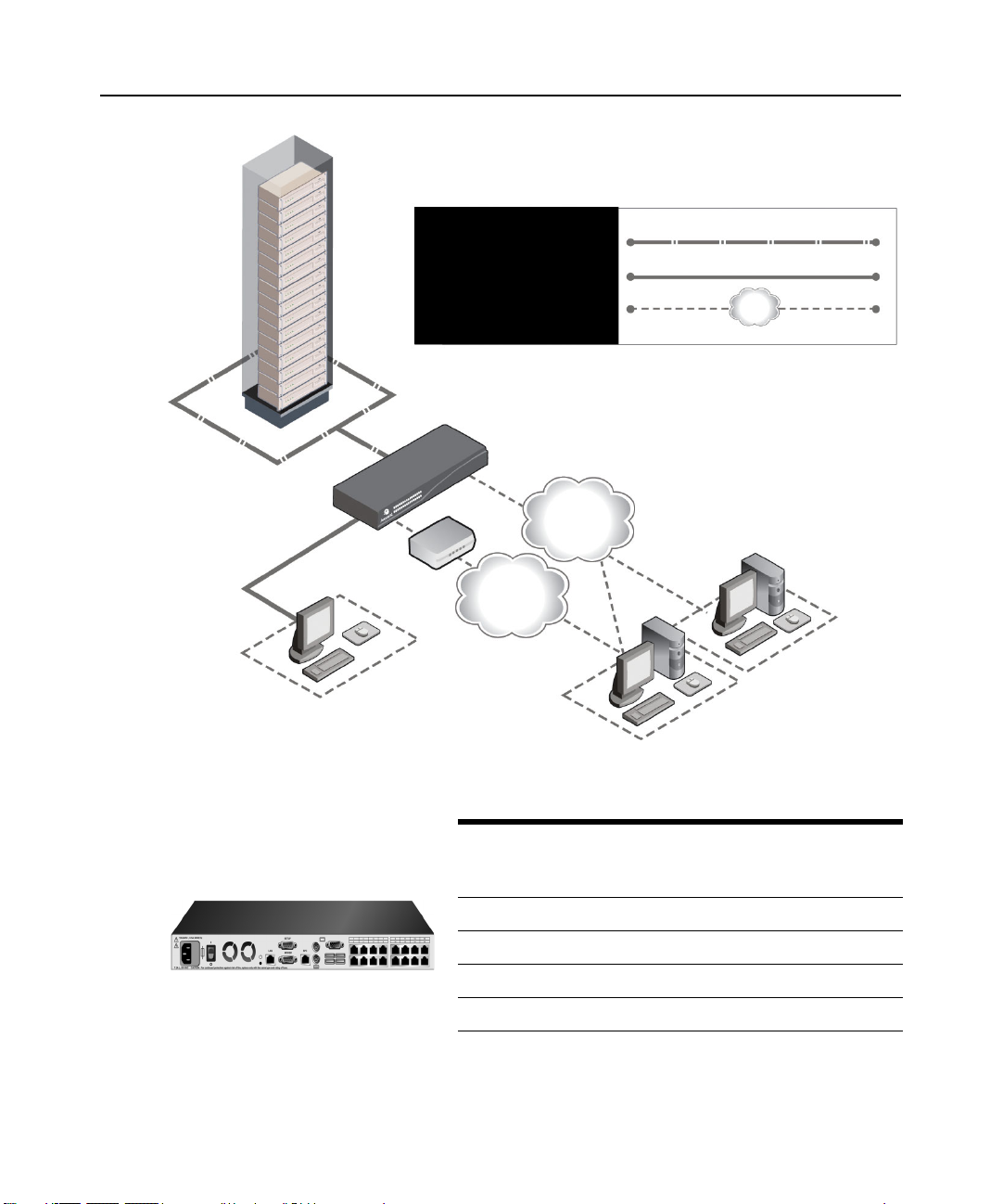
Connexion CAT 5
Connexion KVM au
commutateur
Connexion IP distante
Commutateur DSR
Chapitre 1 : Présentation du produit 3
Ethernet
Modem
Réseau
Utilisateur analogique
(Interface graphique
utilisateur Oscar®)
(Ordinateur équipé d'un navigateur Internet)
Figure 1.1 : Exemple de configuration du commutateur DSR
Modèle de
commutateur
DSR1030 16 1 1 1 1
DSR2030 16 2 1 1 2
DSR4030 16 4 1 1 4
DSR8030 16 8 1 1 8
Nombre
serveurs
de
Trajectoires
numériques
Logiciel
Serveur de logiciel
Utilisateur numérique
Utilisateur
analogique
Sessions
Virtual
Media
locales
Sessions
Virtual
Media
distantes
Figure 1.2 : Comparaison des différents modèles de commutateurs DSR
Page 90

4 Guide d’installation et d’utilisation du commutateur DSR
Mesures de sécurité
Afin d’éviter d’éventuels problèmes de vidéo ou de clavier lors de l’utilisation des produits
Avocent, prenez les précautions suivantes :
• Si le bâtiment est alimenté en courant alternatif triphasé, assurez-vous que l’ordinateur et le
moniteur sont sur la même phase. Pour des résultats optimaux, ils doivent se trouver sur le
même circuit.
Afin d’éviter tout risque de choc mortel et tout dommage matériel, prenez les précautions suivantes :
• N’utilisez jamais de câble d’alimentation à 2 fils avec les produits Avocent.
• Vérifiez la polarité et la mise à la terre des prises de courant alternatif de l’équipement cible et
du moniteur.
• Utilisez uniquement des prises de courant reliées à la terre, pour l’équipement cible et le
moniteur. Lors de l’utilisation d’une alimentation de secours (alimentation sans coupure),
mettez hors tension l’équipement cible, le moniteur et le matériel.
NOTA : La meilleure façon de mettre l’équipement hors tension est de le débrancher de la prise de courant.
Consignes de sécurité relatives au montage en rack
• Température ambiante élevée : Si l’équipement se trouve en rack fermé, la température de
fonctionnement du rack peut être supérieure à la température ambiante de la pièce. Veillez à ce
que cette température n’excède pas la température maximale de fonctionnement du
commutateur.
• Circulation d’air réduite : L’équipement doit être monté en rack de façon à maintenir une
circulation de l’air suffisante pour garantir un fonctionnement en toute sécurité.
• Charge mécanique : L’équipement doit être monté en rack de façon à garantir la bonne
répartition des charges mécaniques et à éviter tout danger.
• Surcharge du circuit : Il est important d’effectuer correctement le raccordement du matériel au
circuit d’alimentation en prêtant une attention particulière à l’impact d’un circuit surchargé sur
la protection contre la surintensité et aux risques qu’il présente pour le câblage d’alimentation.
Tenez compte de la charge maximale spécifiée sur la plaque signalétique.
• Mise à la terre : La mise à la terre du dispositif monté en rack doit être respectée. Vérifiez en
particulier les branchements qui ne sont pas reliés directement au circuit de dérivation (lors de
l’utilisation de barrettes de connexion, par exemple).
Page 91

CHAPITRE
2
Le système de commutation DSR nécessite une connexion à un serveur exécutant le logiciel
DSView Server. Le logiciel DSView vous permet de visualiser et de contrôler les équipements
cibles (un par un) reliés au système de commutation DSR. Pour plus d’informations, consultez le
guide d’installation et d’utilisation du DSView.
Le système de commutation DSR transmet les données du clavier, de la vidéo et de la souris entre
les opérateurs et les équipements cibles connectés au commutateur DSR et reliés au réseau via une
connexion Ethernet ou une connexion modem.
Le commutateur DSR utilise le protocole TCP/IP via une connexion Ethernet. Bien qu’Ethernet
10BaseT puisse être utilisé, Avocent recommande un réseau dédié 100BaseT, voire même
1000BaseT.
Le commutateur DSR utilise le protocole point à point (PPP) pour les communications par modem
V.34, V.90 ou V.92.
5
Installation
Installation
Procédez comme suit pour configurer et installer le commutateur DSR :
• Retirez le commutateur DSR de l’emballage et assurez-vous que tous les éléments sont
présents et en bon état. (Consultez la section Démarrage de ce chapitre.)
• Effectuez tous les branchements entre la source d’alimentation, le commutateur DSR, les
équipements cibles, l’équipement SPC en option, la connexion Ethernet et la connexion
modem en option. Consultez la section Connexion du matériel DSR.
• Mettez l’ensemble sous tension et vérifiez que toutes les connexions fonctionnent. Consultez
la section Vérification des connexions.
• Procédez maintenant si vous souhaitez configurer le commutateur DSR en utilisant l’interface
du menu de la console. Reportez-vous au Chapitre 4 pour de plus amples informations.
• Utilisez le logiciel DSView Server pour configurer le commutateur DSR. Reportez-vous au
guide d’installation et d’utilisation du DSView pour des instructions plus détaillées.
• Effectuez les réglages nécessaires au niveau des paramètres de la souris. Consultez la section
Réglage des paramètres de la souris sur les équipements cibles.
Page 92

6 Guide d’installation et d’utilisation du commutateur DSR
Le schéma ci-dessous illustre l'une des configurations possibles avec un commutateur DSR.
Ethernet
Power
d’alimentation
Modem
Réseau
Utilisateur numérique
Commutateur DSR 1030
Connexion
Voie SPC
Utilisateur analogique
Dispositif de contrôle
de l’alimentation
SPC
*Pour ouvrir une session virtual media à partir d’un serveur,
celui-ci doit tout d’abord être connecté au commutateur à l’aide
d’un module DSRIQ compatible virtual media (USB2 ou USB2L).
Serveurs 1 à 16
Voies
1-16
Câble
CAT 5
Modules DSRIQ
Adaptateurs PS/2, USB*,
Sun et série disponibles.
Figure 2.1 : Configuration du commutateur DSR standard
Page 93

Configuration de votre réseau
Le système de commutation DSR utilise des adresses IP pour identifier de manière unique le
commutateur et chaque équipement cible. Il prend en charge le protocole DHCP (Dynamic Host
Configuration Protocol) ainsi que l’adressage IP statique. Avocent recommande de réserver une
adresse IP pour chaque commutateur et de ne pas modifier les adresses tant que les DSR sont
connectés au réseau. Consultez le guide d’installation et d’utilisation DSView pour de plus amples
informations sur la configuration du commutateur DSR à l’aide du logiciel DSView Server ainsi
que sur le fonctionnement de ce dernier avec une connexion TCP/IP.
Démarrage
Avant d'installer le DSR, consultez les listes ci-dessous pour vous assurer que vous disposez de
tous les éléments livrés avec le commutateur DSR ainsi que des autres éléments nécessaires à
l’installation.
Éléments fournis avec le commutateur DSR
• Cordon d’alimentation conforme aux normes locales
• Kit de montage en rack
• Câble null modem
• Guide d’installation et d’utilisation DSR (le présent manuel)
• Guide d’installation rapide du DSR
Chapitre 2 : Installation 7
Autres éléments nécessaires
• Un module DSRIQ par serveur cible ou un module DSRIQ-SRL par équipement série
• Un câble de raccordement CAT 5 par module DSRIQ (câble à 4 paires torsadées non blindées
d’une longueur maximale de 10 m)
• Un câble de raccordement CAT 5 pour la connexion de réseau (câble à 4 paires torsadées non
blindées d’une longueur maximale de 10 m)
• Un module USB2 ou USB2L DSRIQ par serveur cible pour les sessions virtual media
• Logiciel DSView
• Modem et câbles compatibles V.34, V.90 ou V.92 (facultatif)
• Système de contrôle de l’alimentation SPC (facultatif)
Page 94

8 Guide d’installation et d’utilisation du commutateur DSR
Connexion du matériel DSR
NOTA : Le commutateur DSR peut être monté en rack en configuration 1U. Le commutateur DSR n’est pas
compatible avec une configuration 0U.
Connexion et mise sous tension du commutateur DSR :
1. Mettez hors tension l’équipement (ou les équipements) faisant partie de votre système de
commutation DSR. Munissez-vous du cordon d’alimentation fourni avec le commutateur
DSR, puis branchez l’une de ses extrémités dans la prise d’alimentation située à l’arrière du
commutateur DSR et l’autre extrémité dans une prise secteur appropriée.
AVERTISSEMENT : Pour éviter d’endommager votre matériel et écarter tout risque d’électrocution,
respectez les précautions suivantes.
- Ne retirez pas la prise de terre. Cette prise est un élément de sécurité essentiel.
- Branchez le cordon d’alimentation à une prise reliée à la terre et facilement accessible à tout moment.
- Coupez l’alimentation du matériel en débranchant le cordon d’alimentation au niveau de la prise ou
directement sur le matériel.
2. Branchez les câbles du moniteur VGA, du clavier et de la souris PS/2 ou USB dans les voies
correspondantes du commutateur DSR. Vous devez installer un clavier et une souris sur les
voies locales faute de quoi le clavier risque de pas s’initialiser correctement.
3. Choisissez une voie disponible à l’arrière du commutateur DSR. Reliez un câble de
raccordement CAT 5 (câble à quatre paires torsadées, jusqu’à 10 mètres de long) à la voie
DSRIQ sélectionnée, d’une part, et au connecteur RJ45 d’un module DSRIQ, d’autre part.
4. Connectez le module DSRIQ aux voies correspondantes à l’arrière du serveur cible. Répétez
cette procédure pour tous les serveurs que vous souhaitez relier au commutateur DSR.
Reportez-vous aux sections Connexion d’un module DSRIQ à un serveur et Connexion d’un
module DSRIQ à un équipement série pour de plus amples informations.
5. Branchez un câble de raccordement CAT 5 relié à votre réseau Ethernet dans le connecteur
LAN situé à l’arrière du commutateur DSR. Les utilisateurs du réseau auront ainsi accès au
commutateur DSR par cette voie.
6. (Facultatif) Il est également possible d’accéder au commutateur DSR par l’intermédiaire d’un
modem compatible ITU V.92, V.90 ou V.34. Branchez l’une des extrémités d’un câble série à 9
broches dans le connecteur MODEM situé à l’arrière de votre commutateur DSR, Branchez
l’autre extrémité au modem.
NOTA : L’utilisation d’une connexion modem à la place d’une connexion de type réseau local réduit les
performances de votre commutateur DSR.
7. (Facultatif) Branchez l’une des extrémités du câble fourni avec le dispositif de contrôle de
l’alimentation SPC dans la voie SPC du commutateur DSR et reliez l’autre extrémité à
l’équipement SPC. Branchez les cordons d’alimentation connectés aux serveurs cibles dans les
prises d’alimentation SPC. Connectez l’équipement SPC à une prise secteur appropriée.
Page 95

Chapitre 2 : Installation 9
8. Pour configurer le commutateur DSR à l’aide de l’interface de menu de la console, connectez
un terminal ou un logiciel d’émulation de terminal d’exécution informatique (tel que
HyperTerminal
®
) à la voie de configuration (SETUP) située au dos du panneau arrière du
commutateur DSR à l’aide du câble de modem null fourni. Les paramètres du terminal doivent
être les suivants : 9 600 bit/s, 8 bits, 1 bit d’arrêt, pas de parité ni de contrôle de flux. Dans le
cas contraire, passez à l’étape suivante.
9. Mettez sous tension chaque serveur cible, puis le commutateur DSR. Au bout d’une minute
environ, l’initialisation du commutateur se termine et l’étiquette Free (libre) de l’interface
graphique utilisateur d’OSCAR
®
s’affiche sur le moniteur de la voie locale.
10. Utilisez le logiciel DSView Server pour configurer le commutateur. Reportez-vous au guide
d’installation et d’utilisation du DSView pour des instructions plus détaillées.
Connexion d’un module DSRIQ à un serveur
1. Reliez les connecteurs à code couleur du module DSRIQ aux voies clavier, moniteur et souris
correspondantes du premier serveur à relier au commutateur DS.
2. Reliez une extrémité du câble de raccordement CAT 5 au connecteur RJ45 du module DSRIQ.
Reliez l'autre extrémité du câble de raccordement CAT 5 à la voie souhaitée à l'arrière du
commutateur DSR.
3. Répétez cette étape pour tous les serveurs que vous souhaitez connecter.
NOTA : Lors de la connexion d’un module DSRIQ Sun, utilisez un moniteur à synchronisation multiple sur la voie
locale pour prendre en charge les ordinateurs Sun compatibles à la fois avec la norme VGA et les
synchronisations sur le vert ou composites.
Connexion d’un équipement virtual media local
Connectez l’équipement virtual media à l’une des cinq voies USB du commutateur DSR.
NOTA : Vous devez utiliser un module USB ou USB2L DSRIQ pour toutes les sessions virtual media.
Connexion d’un module DSRIQ à un équipement série :
1. Branchez le connecteur série à 9 broches du module DSRIQ-SRL sur la voie série de
l’équipement à relier au commutateur DSR.
2. Reliez une extrémité du câble de raccordement CAT 5 au connecteur RJ45 du module DSRIQSRL. Reliez l'autre extrémité du câble de raccordement CAT 5 à la voie souhaitée à l'arrière du
commutateur DSR.
NOTA : Le module DSRIQ-SRL est un équipement DCE uniquement compatible avec l’émulation de terminal
VT100.
Page 96

10 Guide d’installation et d’utilisation du commutateur DSR
3. Branchez l’alimentation au connecteur approprié du module DSRIQ-SRL. La rallonge de
câble permet d’alimenter jusqu’à quatre modules DSRIQ-SRL à partir d’un point de
raccordement à la source d’alimentation.
4. Branchez l’alimentation du module DSRIQ-SRL sur une prise de courant alternatif appropriée.
Mettez votre équipement série sous tension. Pour de plus amples informations sur le module
DSRIQ-SRL, reportez-vous à l’Annexe C.
Vérification des connexions
Commutateur DSR
Le panneau avant du DSR possède deux voyants se rapportant aux connexions Ethernet. Le voyant
supérieur (vert) est marqué Link. Il s’allume lorsque la bonne connexion au réseau est établie et
clignote lorsque la voie est active. Le voyant inférieur, orange/vert, portant la mention 100/1000,
indique que la communication s’effectue à la vitesse de 100 Mbit/s (orange) ou de 1 000 Mbit/s
(vert) via une connexion Ethernet.
De plus, chaque numéro de voie à l’avant du commutateur DSR comporte deux voyants indiquant
l’état de l’équipement cible : un voyant vert et un voyant orange. Le voyant vert s’allume lorsque
l’équipement cible relié est mis sous tension. Le voyant orange s’allume lorsque cette voie est
sélectionnée.
Modules DSRIQ
Des modules PS/2, Sun, USB, USB2 et USB2L DSRIQ sont disponibles pour relier des serveurs à
votre commutateur DSR. Raccordez vos équipements real media à un poste de travail à l’aide des
modules USB2 et USB2L DSRIQ.
Le module série DSRIQ-SRL permet de connecter un équipement série à votre commutateur DSR.
Il est doté de deux voyants verts marqués respectivement POWER et STATUS. Le voyant d’état
POWER indique que le DSRIQ-SRL relié est sous tension. Le voyant STATUS indique qu’une
connexion a été établie vers un commutateur DSR. Le DSRIQ-SRL empêche une interruption
d’alimentation série éventuelle de l’équipement relié provoquée par une coupure d’alimentation du
module. Il est toutefois possible de générer une interruption série à partir de l’équipement relié en
appuyant sur
Alt-B dans le menu Terminal Applications (Applications du terminal).
Page 97

Chapitre 2 : Installation 11
Configuration du logiciel DSView et réglage des paramètres
de la souris
Configuration du logiciel DSView
Reportez-vous au guide d’installation et d’utilisation du DSView fourni avec le logiciel.
Réglage des paramètres de la souris sur les équipements cibles
Avant de pouvoir utiliser un ordinateur connecté au commutateur DSR en vue d’une utilisation à
distance, un réglage de la vitesse de la souris doit être effectué et l’accélération doit être désactivée.
Il est conseillé d’utiliser le pilote de souris PS/2 par défaut pour les machines fonctionnant sous le
système d’exploitation Microsoft
NOTA : Les options de vitesse et d’accélération de la souris se situent à différents endroits dans l’applet du
panneau de configuration de la souris en fonction des versions de Windows. Si vous ne trouvez pas ces options
en suivant la procédure décrite précédemment, vérifiez les autres onglets de l’applet du panneau de
configuration de la souris.
Réglage des paramètres de la souris pour Windows NT (avec les pilotes par défaut) :
1. À partir du bureau, sélectionnez Démarrer - Paramètres - Panneau de configuration - Souris.
La boîte de dialogue des propriétés de la souris s’affiche.
2. Cliquez sur l’onglet Mouvement du pointeur.
3. Réglez lavitesse du pointeur sur Lente. Ce réglage doit être réalisé pour tous les utilisateurs de
NT accédant à NT via le commutateur DSR.
4. Configurez le paramètre d’accélération sur Aucune pour la synchronisation de la souris.
5. Cliquez sur OK.
6. Cliquez sur Aligner la souris dans la fenêtre du visualisateur de session vidéo DSView pour
réaligner la souris.
®
Windows® (Windows NT®, 2000, XP et Server 2003).
Réglage des paramètres de la souris pour Windows 2000 (avec les pilotes par
défaut) :
1. À partir du bureau, sélectionnez Démarrer - Paramètres - Panneau de configuration - Souris.
La boîte de dialogue des propriétés de la souris s’affiche.
2. Cliquez sur l’onglet Mouvement du pointeur.
3. Réglez la vitesse sur la valeur par défaut de 50% (sixième graduation en partant de la gauche).
4. Configurez le paramètre d’accélération sur Aucune pour la synchronisation de la souris.
5. Cliquez sur OK.
6. Cliquez sur Aligner la souris dans la fenêtre du visualisateur de session vidéo DSView pour
réaligner la souris.
Page 98

12 Guide d’installation et d’utilisation du commutateur DSR
Réglage des paramètres de la souris pour Windows XP ou Server 2003 (avec les
pilotes par défaut) :
1. À partir du bureau, sélectionnez Démarrer - Panneau de configuration - Souris. La boîte de
dialogue des propriétés de la souris s’affiche.
2. Cliquez sur l’onglet Options du pointeur.
3. Réglez la vitesse sur la valeur par défaut de 50% (sixième graduation en partant de la gauche).
4. Décochez la case Améliorer la précision du pointeur.
5. Cliquez sur OK.
6. Cliquez sur Aligner la souris dans la fenêtre du visualisateur de session vidéo DSView pour
réaligner la souris.
Réglage des paramètres de la souris fonctionnant avec un pilote IntelliPoint
1. À partir du bureau, sélectionnez Démarrer - Paramètres - Panneau de configuration - Souris.
La boîte de dialogue des propriétés de la souris s’affiche.
2. Cliquez sur l’onglet Options du pointeur.
3. Réglez la vitesse sur la valeur par défaut qui correspond au point médian de la règle (cinq
graduations de part et d’autre du curseur).
4. Cliquez sur Paramètres avancés. La boîte de dialogue Paramètres avancés de la vitesse du
pointeur s’affiche.
5. Décochez la case Activer l’accélération du pointeur puis cliquez sur OK pour fermer la boîte.
6. Cliquez sur OK pour fermer la boîte de dialogue des propriétés de la souris.
7. Cliquez sur Aligner la souris dans la fenêtre du visualisateur de session vidéo DSView pour
réaligner la souris.
Réglage des paramètres de la souris avec les pilotes Red Hat
®
de Linux® :
®
:
1. Sélectionnez les paramètres de la souris dans les commandes du bureau.
2. Réglez l’accélération au centre du curseur de défilement (la quatrième case à partir de la
gauche) et appliquez les changements.
NOTA : Si vous utilisez une version ancienne du logiciel Red Hat Linux dotée d’un curseur de défilement
numérique, réglez l’accélération de la souris à 1.0 et appliquez les changements.
3. Cliquez sur Aligner la souris dans la fenêtre du visualisateur de session vidéo DSView pour
réaligner la souris.
Page 99

Chapitre 2 : Installation 13
Réglage des paramètres de la souris avec des pilotes Sun Solaris™ :
1. Dans le menu de l’espace de travail, sélectionnez Applications puis Gestionnaire
d’applications. Le gestionnaire d’applications s’ouvre.
2. Cliquez deux fois sur Commandes_Bureau. La fenêtre Gestionnaire d’applications Commandes_Bureau s’ouvre.
3. Cliquez deux fois sur Gestionnaire de configuration de la souris. La boîte de dialogue
correspondante s’ouvre.
4. Configurez l’accélération sur 1 pour la synchronisation de la souris.
5. Cliquez sur OK.
6. Dans la fenêtre du visualisateur de session vidéo DSView, sélectionnez Affichage - Mise à
l’échelle automatique.
7. Dans la fenêtre du visualisateur de session vidéo DSView, sélectionnez Outils - Options de
session - Souris. La boîte de dialogue correspondante s’affiche.
8. Sélectionnez le type de mise à l’échelle Normal, puis cliquez sur OK.
9. Cliquez sur Aligner la souris dans la fenêtre du visualisateur de session vidéo DSView pour
réaligner la souris.
Page 100

14 Guide d’installation et d’utilisation du commutateur DSR
 Loading...