

Page 1
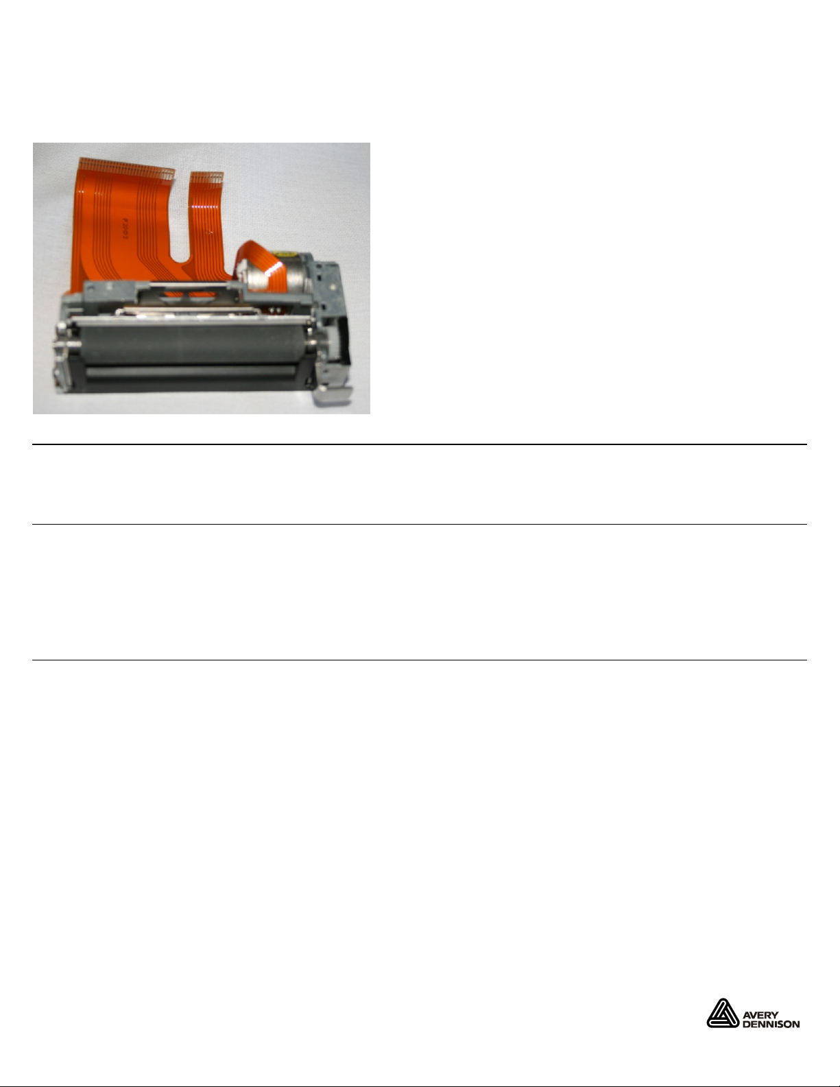
REPLACING THE PRINTHEAD
Use these instructions to replace the printhead assembly in the 9417 Printer.
Audience
These instructions are intended for a skilled service technician only. For additional information or
assistance, call Service at 1-800-543-6650.
Cautions
The 9417 printer contains devices that are sensitive to electrostatic discharge (ESD); failure to
exercise caution can damage the printer. We recommend using an ESD wrist strap, grounding
mat, or grounding workbench when performing maintenance on the printer.
Flex connectors between components and board assemblies are extremely fragile; when
damaged, they require component or board assembly replacement.
Required Tools
The procedures require the following:
A hard, dry surface to set the printer on
Phillips screwdriver
Tape (can be clear adhesive tape, black electrical tape)
Avery Dennison® is a registered trademark of Avery Dennison Corporation. ©2013 Avery Dennison Corp. All Rights Reserved.
TC9417PHI Rev. AA 8/13
Page 2
Removing the Printhead
1. Turn off the printer and unplug it from the electrical outlet.
2. Open the front cover.
3. Remove the supplies.
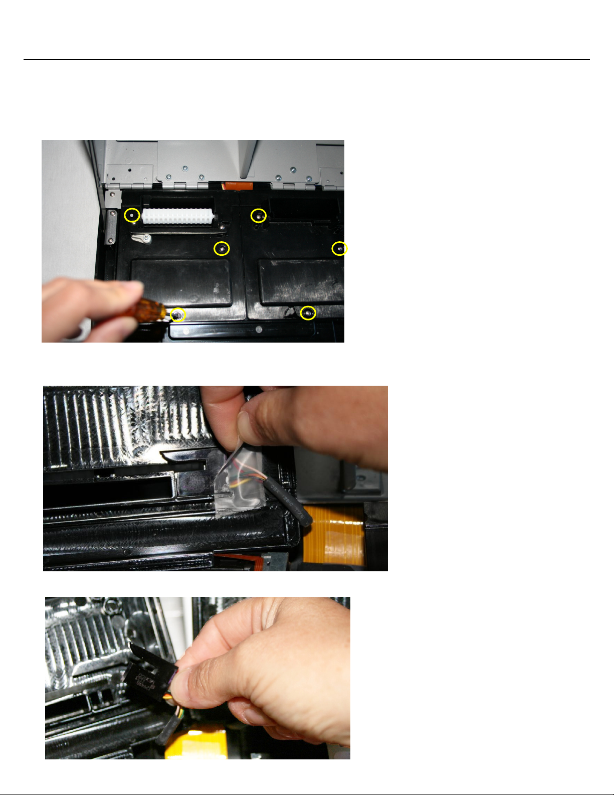
4. Remove the six screws that attach the print module covers.
Lift out the right printer cover then the left printer cover.
5.
6. Remove the tape holding the sensor in place.
Remove the sensor from the print module cover.
7.
2 Replacing the Printhead
Page 3

8. Open the four black flex connector latches. Remove the flex from the flex connector
Flex Connectors
Flex Connector Latch
Note:
9. t
Lift out he printhead assembly.
Apply careful, even pressure on the latches when opening and closing.
Installing the Printhead
1. Make sure the four black flex connector latches are open, then insert the printhead flex into the
flex connector. Make sure the flex is inserted all the way into the connector.
2. Close all four of the black flex connector latches.
Note:
Apply careful, even pressure
on the latches when opening and closing.
3. e
Lay th printhead assembly into place.
Replacing the Printhead 3
Page 4

4. Set the sensor in place on the print module cover. Use a piece of tape to hold it in place.
Note: Be sure the tape is
not covering the
supply path opening.
5.
Lay the left print module cover in place then lay the right print module cover in place.
6. Secure the printer covers in place.
4 Replacing the Printhead
 Loading...