


07530
0753 type
07530 - 07532
I n s t r u c t i o n M a n u a l
Pass onto user to read and keep for reference
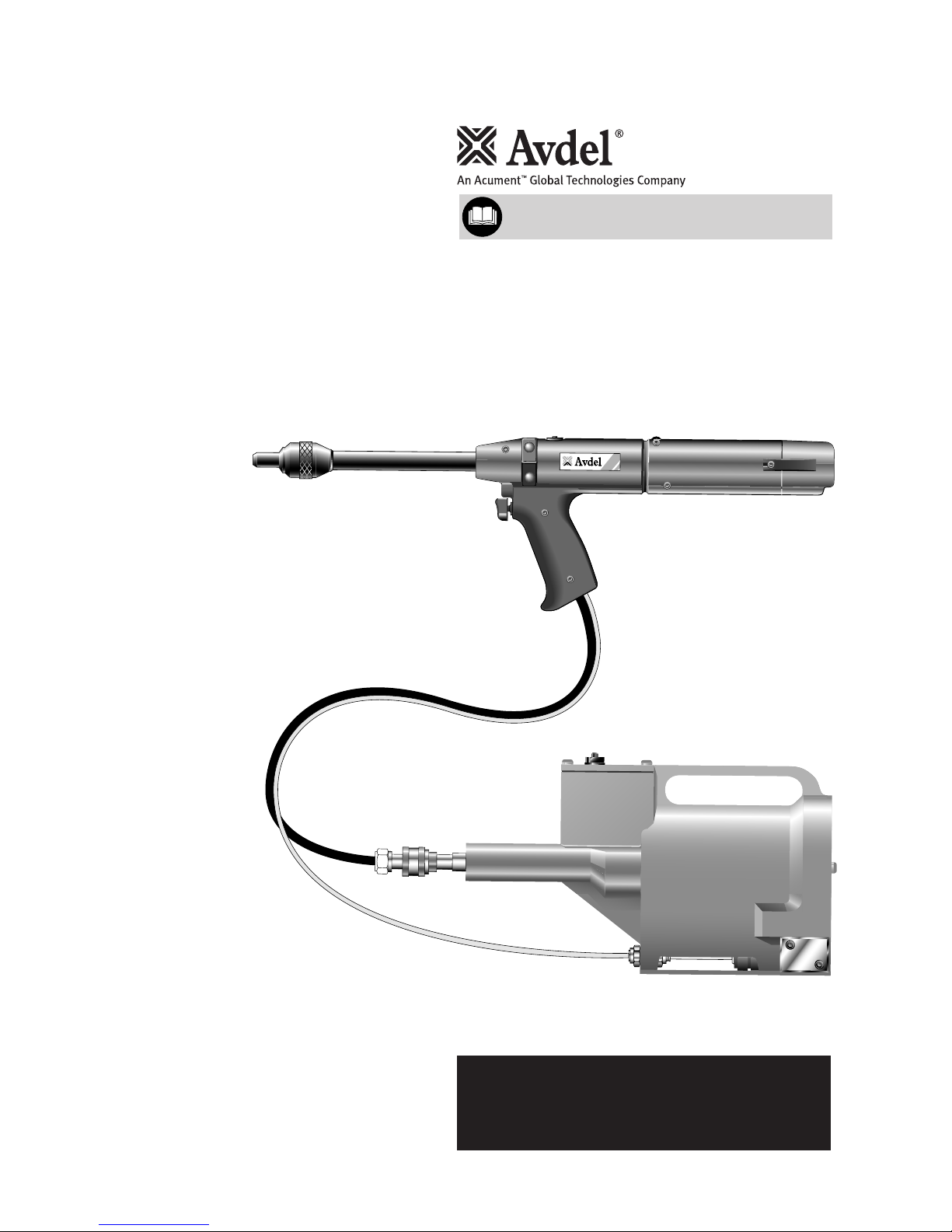
0753
TYPE
Hydro-Pneumatic Power Tool

AIR PRESSURE Minimum - Maximum 5 - 7 bar 70 - 100 lbf/in
2
FREE AIR VOLUME REQUIRED @ 5.1 bar / 75 lbf/in
2
2.6 litres .09 ft
3
STROKE Minimum 30 mm 1.18 in
PULL FORCE @ 5.5 bar / 80 lbf/in
2
3.89 kN 875 lbf
CYCLE TIME Approximately 1 second
NOISE LEVEL Less than 70 dB(A)
WEIGHT 1.2 kg 2.64 lb
VIBRATION Less than 2.5 m/s
2
8 ft/s
2
S P E C I F I C A T I O N S F O R 0 7 5 3 T Y P E T O O L
AVDEL policy is one of continuous development. Specifications shown in this document may be subject to changes which
may be introduced after publication. For the latest information always consult Avdel.
■
■
■
■
■
■
■
■
■
■
■
■
■
■
■
■
■
■
■
■
■
■
■
■
■
■
■
■
■
AIR PRESSURE Minimum - Maximum 5 - 7 bar 70 - 100 lbf/in
2
INTENSIFICATION RATIO 30:1
S P E C I F I C A T I O N S F O R 0 7 5 3 1 I N T E N S I F I E R

General 2
Specific to 0753 Tool 3
Tool Capability 4
Tool Dimensions 5
Air Supply 6
Cursor 7
Loading the Tool 7
Reloading the Tool 8
Operating Procedure 8
General 10
Nose Jaw Selection 10-13
Mandrel and Mandrel Follower Spring Selection 14-19
Regular Servicing - Service Kit 20-21
Maintenance 21-23
07530 General Assembly & Parts List 24-25
07532 General Assembly & Parts List 26-27
Intensifier Details 28-29
Pilot Valve Details 30-31
Priming Oil Details 32
Priming Procedure 32
Fault Diagnosis Table 33
S A F E T Y
I N T E N T O F U S E
P U T T I N G I N T O S E R V I C E
N O S E E Q U I P M E N T
S E R V I C I N G
P R I M I N G
F A U L T D I A G N O S I S
C
O N T E N T S
1

S
A F E T Y
2
This instruction manual must be read with particular attention to the following safety rules,
by any person installing, operating, or servicing this tool.
DO NOT USE OUTSIDE THE DESIGN INTENT.
DO NOT USE EQUIPMENT WITH THIS TOOL/MACHINE OTHER THAN THAT
RECOMMENDED AND SUPPLIED BY AVDEL.
ANY MODIFICATION UNDERTAKEN BY THE CUSTOMER TO THE TOOL/MACHINE,
NOSE ASSEMBLIES, ACCESSORIES OR ANY EQUIPMENT SUPPLIED BY AVDEL OR THEIR
REPRESENTATIVES, SHALL BE THE CUSTOMER'S ENTIRE RESPONSIBILITY. AVDEL WILL BE
PLEASED TO ADVISE UPON ANY PROPOSED MODIFICATION.
THE TOOL/MACHINE MUST BE MAINTAINED IN A SAFE WORKING CONDITION AT
ALL TIMES AND EXAMINED AT REGULAR INTERVALS FOR DAMAGE AND FUNCTION BY
TRAINED COMPETENT PERSONNEL. ANY DISMANTLING PROCEDURE SHALL BE
UNDERTAKEN ONLY BY PERSONNEL TRAINED IN AVDEL PROCEDURES. DO NOT DISMANTLE
THIS TOOL/MACHINE WITHOUT PRIOR REFERENCE TO THE MAINTENANCE INSTRUCTIONS.
CONTACT AVDEL WITH YOUR TRAINING REQUIREMENTS.
THE TOOL/MACHINE SHALL AT ALL TIMES BE OPERATED IN ACCORDANCE WITH
RELEVANT HEALTH AND SAFETY LEGISLATION. IN THE U.K. THE “HEALTH AND SAFETY AT
WORK ETC. ACT 1974” APPLIES. ANY QUESTION REGARDING THE CORRECT OPERATION
OF THE TOOL/MACHINE AND OPERATOR SAFETY SHOULD BE DIRECTED TO AVDEL.
THE PRECAUTIONS TO BE OBSERVED WHEN USING THIS TOOL/MACHINE MUST BE
EXPLAINED BY THE CUSTOMER TO ALL OPERATORS.
ALWAYS DISCONNECT THE AIRLINE FROM THE TOOL/MACHINE INLET BEFORE
ATTEMPTING TO ADJUST, FIT OR REMOVE A NOSE ASSEMBLY.
DO NOT OPERATE A TOOL/MACHINE THAT IS DIRECTED TOWARDS ANY PERSON(S).
ALWAYS ADOPT A FIRM FOOTING OR A STABLE POSITION BEFORE OPERATING THE
TOOL/MACHINE.
ENSURE THAT VENT HOLES DO NOT BECOME BLOCKED OR COVERED AND THAT
HOSES ARE ALWAYS IN GOOD CONDITION.
THE COMBINATION OF FASTENER, MANDREL, HOLE SIZE AND SHEET THICKNESS
SHALL BE IN ACCORDANCE WITH AVDEL SPECIFICATIONS.

In addition to the general safety rules opposite, the following specific safety points must also
be observed:
WHEN USING THE TOOL, THE WEARING OF SAFETY GLASSES IS REQUIRED BOTH BY
THE OPERATOR AND OTHERS IN THE VICINITY TO PROTECT AGAINST FASTENER EJECTION,
SHOULD A FASTENER BE PLACED ‘IN AIR’. WE RECOMMEND WEARING GLOVES IF THERE
ARE SHARP EDGES OR CORNERS ON THE APPLICATION.
THE OPERATING PRESSURE SHALL NOT EXCEED 7 BAR - 100 LBF/IN2.
DO NOT OPERATE THE TOOL WITHOUT FULL NOSE EQUIPMENT IN PLACE.
TAKE CARE TO AVOID ENTANGLEMENT OF LOOSE CLOTHES, TIES, LONG HAIR,
CLEANING RAGS ETC… IN THE MOVING PARTS OF THE TOOL WHICH SHOULD BE KEPT
DRY AND CLEAN FOR BEST POSSIBLE GRIP.
WHEN CARRYING THE TOOL FROM PLACE TO PLACE KEEP HANDS AWAY FROM THE
TRIGGER/LEVER TO AVOID INADVERTENT START UP.
EXCESSIVE CONTACT WITH HYDRAULIC OIL SHOULD BE AVOIDED. TO MINIMIZE THE
POSSIBILITY OF RASHES, CARE SHOULD BE TAKEN TO WASH THOROUGHLY.
3
I M P O R T A N T
WHILE A SMALL AMOUNT OF WEAR AND MARKING WILL NATURALLY OCCUR THROUGH
NORMAL AND CORRECT USE OF MANDRELS, THEY MUST BE REGULARLY EXAMINED FOR
EXCESSIVE WEAR AND MARKING, WITH PARTICULAR ATTENTION TO THE HEAD DIAMETER,
THE TAIL JAW GRIPPING AREA OF THE SHANK OR HEAVY PITTING OF THE SHANK AND
ANY MANDREL DISTORTION. MANDRELS WHICH FAIL DURING USE COULD FORCIBLY EXIT
THE TOOL. IT IS THE CUSTOMER’S RESPONSIBILITY TO ENSURE THAT MANDRELS ARE
REPLACED BEFORE ANY EXCESSIVE LEVELS OF WEAR AND ALWAYS BEFORE THE MAXIMUM
RECOMMENDED NUMBER OF PLACINGS. CONTACT YOUR AVDEL REPRESENTATIVE WHO
WILL LET YOU KNOW WHAT THAT FIGURE IS BY MEASURING THE BROACH LOAD OF YOUR
APPLICATION WITH OUR CALIBRATED MEASURING TOOL. THESE TOOLS CAN ALSO BE
PURCHASED UNDER PART NUMBER 07900-09080, SUPPLIED WITH ALL NECESSARY
INFORMATION FOR TESTING.

4
I
N T E N T O F U S E
The pneumatic 0753 type tool is designed to place Avdel repetition fasteners (except 1/16” Avlug) making it ideal for batch or flow-line
assembly in a wide variety of applications throughout all industries.
Both models, the 07530 and 07532 are hand-held lightweight tools. Their only difference lies in the location of the hose entry. The top
entry on the 07532 tool allows supension from an added mounting plate, see drawing opposite. Part numbers are shown to order a
complete tool including the intensifier and all hoses but no nose equipment.
The base tool part number for the 07530 model is 07530-00200 and is 07532-00200 for the 07532 model. See the general assemblies
on pages 24 to 27.
Both models will place the same fasteners and both will place most repetition fasteners, as shown in the table below.
Both models make use of the same nose equipment. Reference must be made to the Nose Equipment section of the manual when selecting
compatible components for the type and size of fastener used in your application (see pages 10 to 19). Nose jaw dimensions are shown
on page 11 and stated on pages 12 and 13.
FASTENER NAME
2.5mm
2.8mm
●●●
●
●●
FASTENER SIZE
CHOBERT
GROVIT
AVLUG
BRIV
RIVSCREW
AVTRONIC
AVSERT
●●●●●
●●●●
●●
●●●●
3
/32"
1
/4"
3
/16"
5
/32"
1
/8"
M3
6-32
UNC
M2.5
4-40
UNC
4mm3.5mm3mm
5
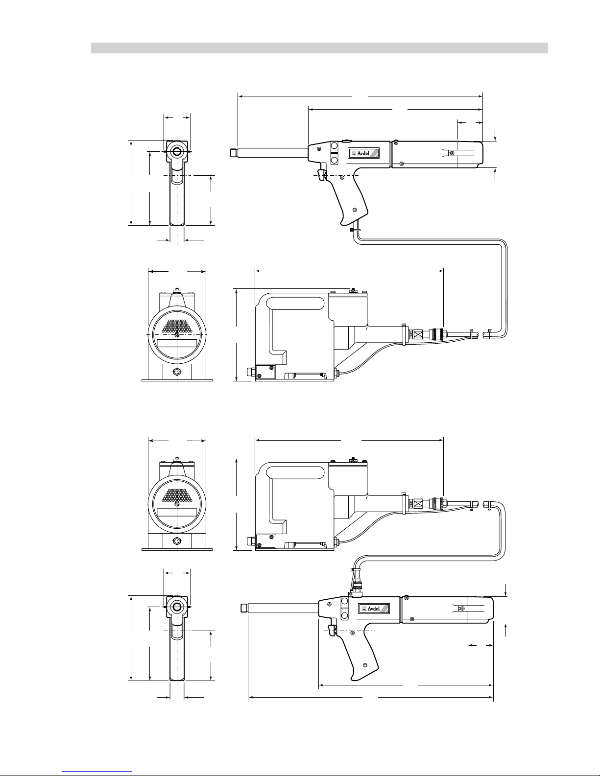
Dimensions shown in bold are millimetres. Other dimensions are in inches.
07530 MODEL
part number 07530-00100
60
2.36
28
1.10
98
3.85
163
6.41
140
5.51
0753
475
18.70
338
13.30
5
1
2
50
1.96
130
5.12
200
7.87
420
16.54
07532 MODEL
part number 07532-00100
0753
60
2.36
28
1.10
98
3.85
200
7.87
130
5.12
420
16.54
475
18.70
338
13.30
51
2
163
6.41
140
5.51
50
1.96
6
A I R S U P P L Y
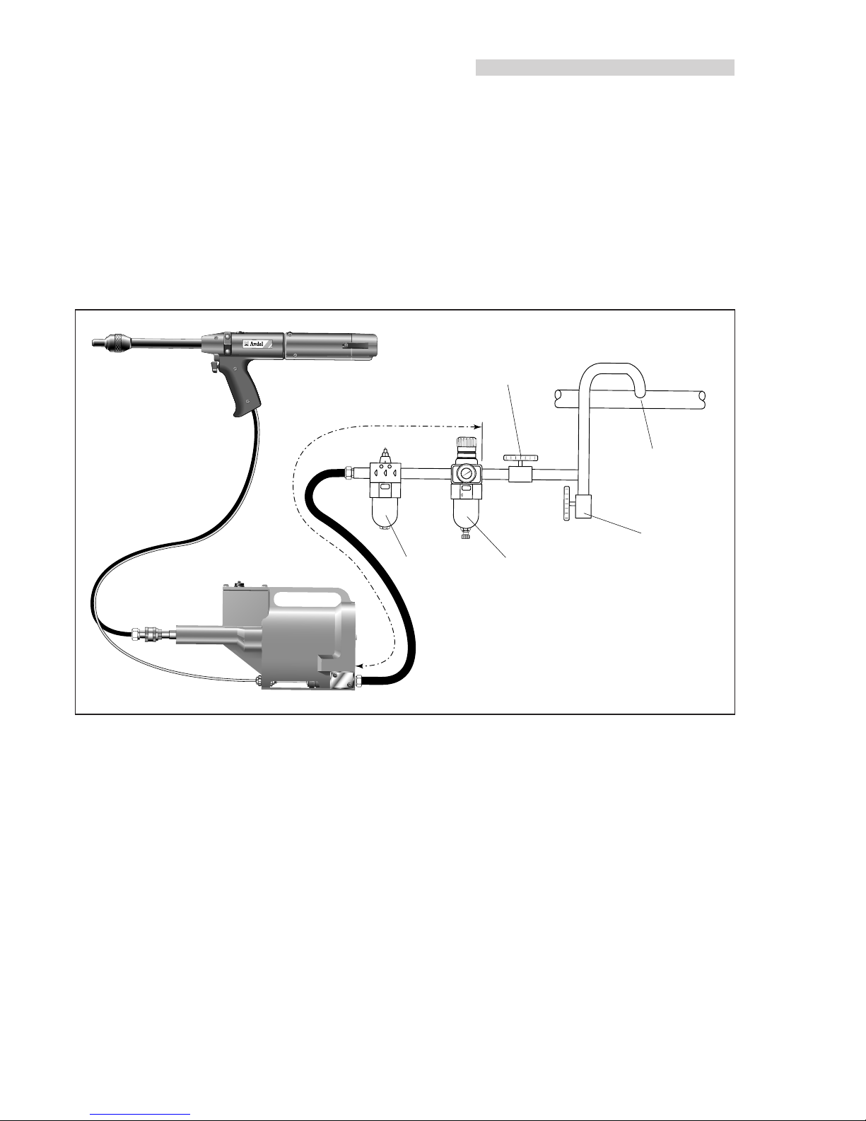
All tools are operated with compressed air at an optimum pressure of 5.5 bar. We recommend the use of pressure regulators and
automatic oiling/filtering systems on the main air supply. To ensure maximum tool life and minimum tool maintenance they should be
fitted within 3 metres of the tool (see diagram below).
Air supply hoses should have a minimum working effective pressure rating of 150% of the maximum pressure produced in the system
or 10 bar, whichever is the highest. Air hoses should be oil resistant, have an abrasion resistant exterior and should be armoured where
operating conditions may result in hoses being damaged. All air supply hoses MUST have a minimum bore diameter of 6.4 millimeters
or 1/4 inch.
Read servicing daily details page 20.
P
U T T I N G I N T O S E R V I C E
Follow the steps below when connecting the tool to the intensifier and main air supply:
Push and turn the end of the larger hose from the tool into the quick release connector on the end of the intensifier.
Push the smaller hose from the tool into the plastic collet of the bulkhead connector on the front face of the intensifier.
Fit a hose between the male connector at the rear of the intensifier and the main air supply.
■
■
■
0753
T
Y
P
E
8
6
4
2
0
10
12
14
16
TAKE OFF POINT
FROM MAIN SUPPLY
STOP COCK
(USED DURING MAINTENANCE
OF FILTER/REGULATOR
OR LUBRICATION UNITS)
MAIN SUPPLY
DRAIN POINT
PRESSURE REGULATOR
AND FILTER
(DRAIN DAILY)
LUBRICATOR
3
M
E
T
R
E
S
M
A
X
I
M
U
M
C U R S O R
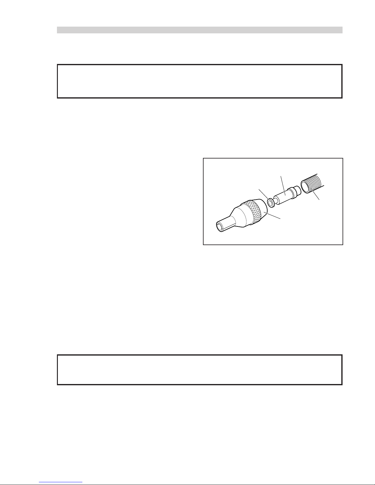
While the cursor will be fitted the correct way round when the tool is supplied, we recommend that you check its orientation before fitting
the nose equipment. The sprung loaded, slightly concave, end of the cursor should point towards the front of the tool as shown in the
illustration below.
When fitted the correct way round, the cursor will easily slide out of the barrel when a mandrel is pushed into its centre then pulled
back.
To reverse the orientation of the cursor, follow these steps:
Item numbers in bold refer to the general assembly and parts list
on pages 24 to 27.
Slacken two screws 53 and slide off end cap 51.
Locate circlip pliers into the two holes of protective cover 1 and
using an allen key, remove screw 2 and sealing ring 3.
Lift off protective cover 1 and second sealing ring 3.
Using circlip pliers, remove circlip 50.
Remove rear plug 4.
Pull out tail jaw piston assembly 8 together with jaws 48.
Lift out spring 7 and jaw housing 47.
Insert a mandrel into the hole in the rear end of barrel 38 until it protrudes throught the front of the barrel, then pull out the mandrel
and cursor together through the front.
Reassemble components in reverse order.
Insert cursor 76 into the front of the barrel, correct way round.
7
When ordering a complete tool or system you will normally be supplied with all the nose equipment required for the fastener to be
placed. To identify nose equipment components or to select the correct elements, read the nose equipment section, on pages 10 to 19.
If you have been supplied with a nose jaw, mandrels and mandrel follower springs proceed with loading the tool and fitting the nose
equipment as follows:
Item numbers in bold refer to the general assembly and parts list on pages 24 to 27.
L O A D I N G T H E T O O L
I M P O R T A N T
If fitted incorrectly, the cursor will not allow feeding of the fasteners.
I M P O R T A N T
The procedure for loading the tool and for fitting the nose equipment to the tool are integral.
NOSE
JAWS
TOO
L
BARR
EL
CURSOR
SPRING
LOADED END
■
■
■
■
■
■
■
■
■
■
8
Connect the air supply to the tool.
Open tail jaws 48 which grip the mandrel, by switching off the tail jaw switch (items 32 & 36).
Screw selected nose jaws onto barrel 38 of the tool.
Insert a mandrel into the tail end of the fasteners through the paper pod.
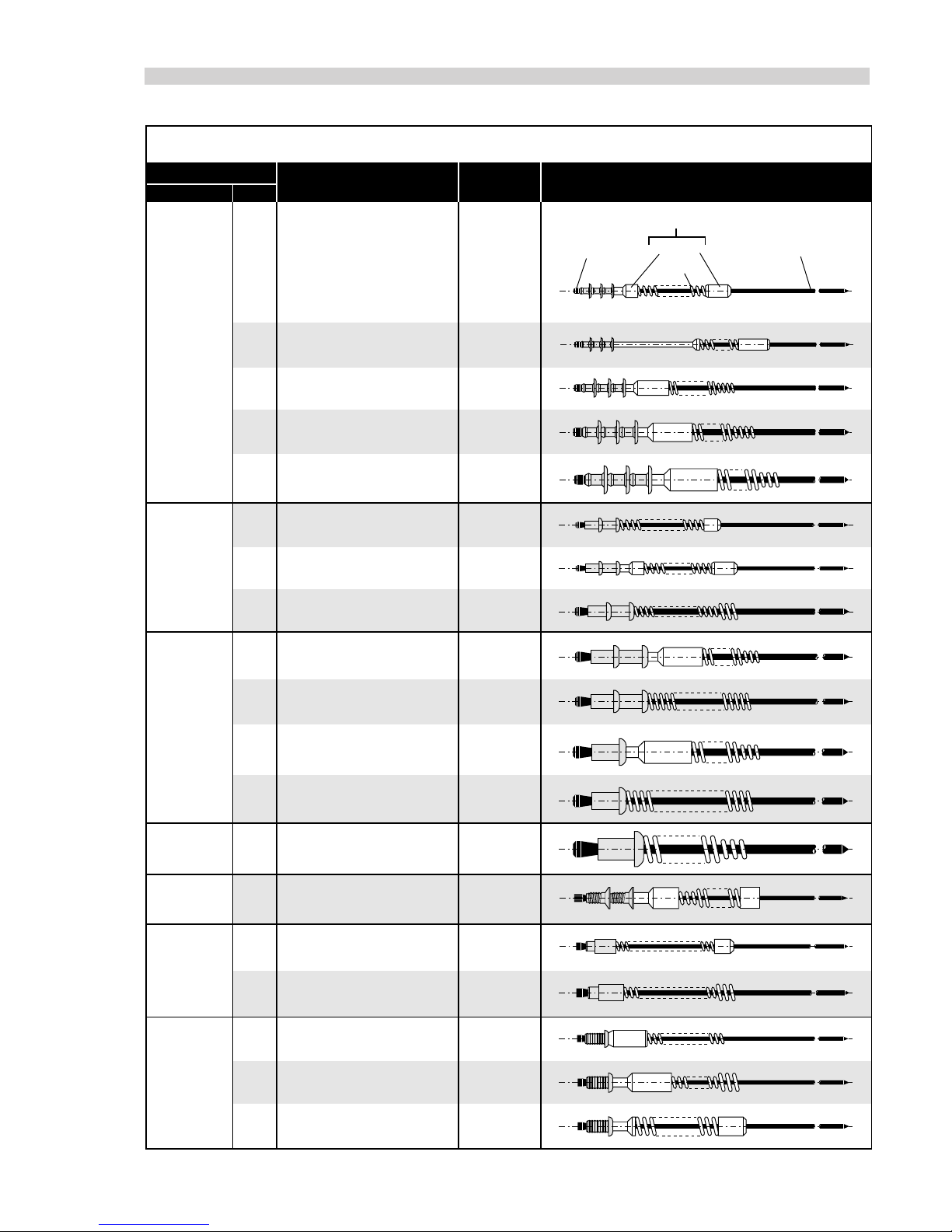
Slide the mandrel follower spring onto the mandrel ENSURING correct orientation, as shown in the table on page 9.
Gripping the tail end of the mandrel, tear off the paper pod from around the fasteners.
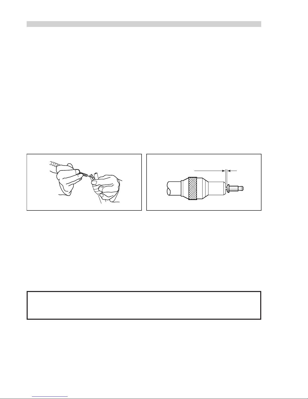
Open the nose jaws either by rotating the outer ring on Cam operated jaws or by pushing outwards on the jaw ends, as illustrated
below left.
Insert the previously assembled mandrel, mandrel follower spring and fasteners into the nose jaws until the first fastener to be
placed is protuding from the nose jaw.
Close the nose jaws and adjust so that the first fastener protrudes by 1.5mm - 3mm (1/16” to 1/8 ”), as shown in the illustration
below right.
Close the tail jaws to ensure the mandrel is gripped.
■
■
■
■
■
■
■
■
■
■
1.5mm - 3mm
(
1
/16" - 1/8")
Push the fastener, protruding from the nose jaws, fully into the application holes ensuring that the tool is held square.
Operate the trigger without releasing - the mandrel head is pulled through the fastener, forming the fastener into the application.
Remove the tool.
Release the trigger. The next fastener will be automatically presented through the nose jaws, ready for placing.
■
■
■
■
R E L O A D I N G T H E T O O L
Open tail jaws 48 of tool.
Open the nose jaws and pull the empty mandrel and mandrel follower spring out of the tool.
Reload the tool by following the above instructions, starting at stage ■.
■
■
■
O P E R A T I N G P R O C E D U R E
I M P O R T A N T
It is essential to check that the cursor orientation and the nose equipment are correct before attempting to operate the tool.
9
3
/16"
3
/32"
3
/32"
5
/32"
5
/32"
3
/16"
3
/16"
3mm
6 x 32
UNC
2.5mm
4 x 40
UNC
3
/32"
3
/32"
1
/8"
1
/4"
1
/8"
2.8mm
2.5mm
3mm
3.5mm
4mm
2.8mm
CHOBERT
AVLUG
GROVIT
CHOBERT
GROVIT
CHOBERT
RIVSCREW
BRIV
AVSERT
AVTRONIC
MANDREL HEAD
FERRULE
MANDREL FOLLOWER SPRING
SPRING
MANDREL
STANDARD TAPERED
ALL
ALL
ALL
ALL EXCEPT
STANDARD TAPERED,
LIMITED ACCESS
ALL EXCEPT
LIMITED ACCESS
STANDARD TAPERED,
LIMITED ACCESS
ALL
ALL
ALL
ALL
ALL
ALL
ALL
ALL
ALL
ALL
LIMITED ACCESS
5
/32"
FASTENER
SIZENAME
NOSE JAW
(SEE NOSE EQUIPMENT SECTION)
ALL
ALL
ALL
ALL
ALL
ALL
ALL
ALL
ALL EXCEPT
3rd
OVERSIZE
3rd
OVERSIZE
ALL EXCEPT
2nd
OVERSIZE
2nd
OVERSIZE
ALL
ALL
ALL
ALL
ALL
ALL
ALL
MANDREL
SIZE
MANDREL FOLLOWER SPRINGS IDENTIFICATION AND ORIENTATION
MANDREL/MANDREL FOLLOWER SPRING
AND FASTENER ASSEMBLY
LIMITED ACCESS &
LIMITED ACCESS CAM OPERATED
 Loading...