

Page 1

Configuring IPv6
Services
BayRS V ersion 12.00
Site Manager Software Version 6.00
Part No. 118428-A Rev. A
September 1997
Page 2

4401 Great America Parkway 8 Federal Street
Santa Clara, CA 95054 Billerica, MA 01821
Copyright © 1997 Bay Networks, Inc.
All rights reserved. Printed in the USA. September 1997.
The information in this document is subject to change without notice. The statements, configurations, technical data,
and recommendations in this document are believed to be accurate and reliable, but are presented without express or
implied warranty . Users must tak e full responsibility for their applications of an y products specified in this document.
The information in this document is proprietary to Bay Networks, Inc.
The software described in this document is furnished under a license agreement and may only be used in accordance
with the terms of that license. A summary of the Software License is included in this document.
Trademarks
ACE, AFN, AN, BCN, BLN, BN, BNX, CN, FN, FRE, GAME, LN, PPX, and Bay Networks are registered
trademarks and Advanced Remote Node, ANH, ARN, ASN, Bay•SIS, BayStack, BayStream, BCNX, BLNX,
IP AutoLearn, SN, SPEX, Switch Node, System 5000, Bay Networks Press, and the Bay Networks logo are
trademarks of Bay Networks, Inc.
All other trademarks and registered trademarks are the property of their respective owners.
Restricted Rights Legend
Use, duplication, or disclosure by the United States Government is subject to restrictions as set forth in subparagraph
(c)(1)(ii) of the Rights in Technical Data and Computer Software clause at DFARS 252.227-7013.
Notwithstanding any other license agreement that may pertain to, or accompany the delivery of, this computer
software, the rights of the United States Government regarding its use, reproduction, and disclosure are as set forth in
the Commercial Computer Software-Restricted Rights clause at FAR 52.227-19.
Statement of Conditions
In the interest of improving internal design, operational function, and/or reliability, Bay Networks, Inc. reserves the
right to make changes to the products described in this document without notice.
Bay Networks, Inc. does not assume any liability that may occur due to the use or application of the product(s) or
circuit layout(s) described herein.
Portions of the code in this software product are Copyright © 1988, Regents of the Univ ersity of California. All rights
reserved. Redistribution and use in source and binary forms of such portions are permitted, provided that the above
copyright notice and this paragraph are duplicated in all such forms and that any documentation, advertising materials,
and other materials related to such distribution and use acknowledge that such portions of the software were
developed by the University of California, Berkeley. The name of the University may not be used to endorse or
promote products derived from such portions of the software without specific prior written permission.
SUCH PORTIONS OF THE SOFTWARE ARE PROVIDED “AS IS” AND WITHOUT ANY EXPRESS OR
IMPLIED WARRANTIES, INCLUDING, WITHOUT LIMITATION, THE IMPLIED WARRANTIES OF
MERCHANTABILITY AND FITNESS FOR A PARTICULAR PURPOSE.
In addition, the program and information contained herein are licensed only pursuant to a license agreement that
contains restrictions on use and disclosure (that may incorporate by reference certain limitations and notices imposed
by third parties).
Bay Networks, Inc. Software License Agreement
NOTICE:
installing the hardware unit with pre-enabled software (each of which is referred to as “Software” in this Agreement).
ii
Please carefully read this license agreement before copying or using the accompanying software or
118428-A Rev. A
Page 3

BY COPYING OR USING THE SOFTWARE, YOU A CCEPT ALL OF THE TERMS AND CONDITIONS OF THIS
LICENSE AGREEMENT. THE TERMS EXPRESSED IN THIS AGREEMENT ARE THE ONLY TERMS UNDER
WHICH BAY NETWORKS WILL PERMIT YOU TO USE THE SOFTWARE. If you do not accept these terms and
conditions, return the product, unused and in the original shipping container, within 30 days of purchase to obtain a
credit for the full purchase price
1. License Grant.
nonexclusive, nontransferable license: a) to use the Software either on a single computer or, if applicable, on a single
authorized device identified by host ID, for which it was originally acquired; b) to copy the Software solely for backup
purposes in support of authorized use of the Software; and c) to use and copy the associated user manual solely in
support of authorized use of the Software by Licensee. This license applies to the Software only and does not extend
to Bay Networks Agent software or other Bay Networks software products. Bay Networks Agent software or other
Bay Networks software products are licensed for use under the terms of the applicable Bay Networks, Inc. Software
License Agreement that accompanies such software and upon payment by the end user of the applicable license fees
for such software.
2. Restrictions on use; reservation of rights.
Bay Networks and/or its licensors retain all title and ownership in both the Software and user manuals, including any
revisions made by Bay Networks or its licensors. The copyright notice must be reproduced and included with any
copy of any portion of the Software or user manuals. Licensee may not modify, translate, decompile, disassemble, use
for any competitive analysis, reverse engineer, distribute, or create derivative works from the Software or user
manuals or any copy, in whole or in part. Except as expressly provided in this Agreement, Licensee may not copy or
transfer the Software or user manuals, in whole or in part. The Software and user manuals embody Bay Networks’ and
its licensors’ confidential and proprietary intellectual property. Licensee shall not sublicense, assign, or otherwise
disclose to any third party the Software, or any information about the operation, design, performance, or
implementation of the Software and user manuals that is confidential to Bay Networks and its licensors; however,
Licensee may grant permission to its consultants, subcontractors, and agents to use the Software at Licensee’s f acility,
provided they have agreed to use the Software only in accordance with the terms of this license.
3. Limited warranty.
installed and operated on Bay Networks hardware or other equipment it is originally licensed for, to function
substantially as described in its accompanying user manual during its warranty period, which begins on the date
Software is first shipped to Licensee. If any item of Software fails to so function during its warranty period, as the sole
remedy Bay Networks will at its discretion provide a suitable fix, patch, or workaround for the problem that may be
included in a future Software release. Bay Networks further warrants to Licensee that the media on which the
Software is provided will be free from defects in materials and workmanship under normal use for a period of 90 days
from the date Software is first shipped to Licensee. Bay Networks will replace defective media at no charge if it is
returned to Bay Networks during the warranty period along with proof of the date of shipment. This warranty does not
apply if the media has been damaged as a result of accident, misuse, or abuse. The Licensee assumes all responsibility
for selection of the Software to achieve Licensee’s intended results and for the installation, use, and results obtained
from the Software. Bay Networks does not warrant a) that the functions contained in the software will meet the
Licensee’s requirements, b) that the Software will operate in the hardw are or softw are combinations that the Licensee
may select, c) that the operation of the Software will be uninterrupted or error free, or d) that all defects in the
operation of the Software will be corrected. Bay Networks is not obligated to remedy any Software defect that cannot
be reproduced with the latest Software release. These warranties do not apply to the Software if it has been (i) altered,
except by Bay Networks or in accordance with its instructions; (ii) used in conjunction with another vendor’s product,
resulting in the defect; or (iii) damaged by improper environment, abuse, misuse, accident, or negligence. THE
FOREGOING WARRANTIES AND LIMITATIONS ARE EXCLUSIVE REMEDIES AND ARE IN LIEU OF ALL
OTHER WARRANTIES EXPRESS OR IMPLIED, INCLUDING WITHOUT LIMITATION ANY WARRANTY OF
MERCHANT ABILITY OR FITNESS FOR A PARTICULAR PURPOSE. Licensee is responsible for the security of
its own data and information and for maintaining adequate procedures apart from the Software to reconstruct lost or
altered files, data, or programs.
4. Limitation of liability.
COST OF SUBSTITUTE PROCUREMENT; SPECIAL, INDIRECT, INCIDENTAL, OR CONSEQUENTIAL
DAMAGES; OR ANY DAMAGES RESULTING FROM INACCURATE OR LOST DATA OR LOSS OF USE OR
Bay Networks, Inc. (“Bay Networks”) grants the end user of the Software (“Licensee”) a personal,
The Software and user manuals are protected under copyright laws.
Bay Networks warrants each item of Software, as delivered by Bay Networks and properly
IN NO EVENT WILL BAY NETWORKS OR ITS LICENSORS BE LIABLE FOR ANY
118428-A Rev. A
iii
Page 4

PROFITS ARISING OUT OF OR IN CONNECTION WITH THE PERFORMANCE OF THE SOFTWARE, EVEN
IF BAY NETWORKS HAS BEEN ADVISED OF THE POSSIBILITY OF SUCH DAMAGES. IN NO EVENT
SHALL THE LIABILITY OF BAY NETWORKS RELATING TO THE SOFTWARE OR THIS AGREEMENT
EXCEED THE PRICE PAID TO BAY NETWORKS FOR THE SOFTWARE LICENSE.
5. Government Licensees.
by or on behalf of the United States Government. The Software and documentation are commercial products, licensed
on the open market at market prices, and were developed entirely at private expense and without the use of any U.S.
Government funds. The license to the U.S. Government is granted only with restricted rights, and use, duplication, or
disclosure by the U.S. Government is subject to the restrictions set forth in subparagraph (c)(1) of the Commercial
Computer Software––Restricted Rights clause of F AR 52.227-19 and the limitations set out in this license for civilian
agencies, and subparagraph (c)(1)(ii) of the Rights in Technical Data and Computer Software clause of DFARS
252.227-7013, for agencies of the Department of Defense or their successors, whichever is applicable.
6. Use of Software in the European Community.
European Community. If Licensee uses the Software within a country in the European Community, the Software
Directive enacted by the Council of European Communities Directive dated 14 May, 1991, will apply to the
examination of the Software to facilitate interoperability. Licensee agrees to notify Bay Networks of any such
intended examination of the Software and may procure support and assistance from Bay Networks.
7. Term and termination.
Bay Networks’ copyright in the Software and user manuals will cease being effective at the date of expiration of the
Bay Networks copyright; those restrictions relating to use and disclosure of Bay Networks’ confidential information
shall continue in effect. Licensee may terminate this license at any time. The license will automatically terminate if
Licensee fails to comply with any of the terms and conditions of the license. Upon termination for any reason,
Licensee will immediately destroy or return to Bay Networks the Software, user manuals, and all copies. Bay
Networks is not liable to Licensee for damages in any form solely by reason of the termination of this license.
8. Export and Re-export.
or information without first obtaining any required export licenses or other governmental approvals. Without limiting
the foregoing, Licensee, on behalf of itself and its subsidiaries and affiliates, agrees that it will not, without first
obtaining all export licenses and approvals required by the U.S. Government: (i) export, re-export, transfer, or divert
any such Software or technical data, or any direct product thereof, to any country to which such exports or re-exports
are restricted or embargoed under United States export control laws and regulations, or to any national or resident of
such restricted or embargoed countries; or (ii) provide the Software or related technical data or information to any
military end user or for any military end use, including the design, development, or production of any chemical,
nuclear, or biological weapons.
9. General.
jurisdiction, the remainder of the provisions of this Agreement shall remain in full force and effect. This Agreement
will be governed by the laws of the state of California.
Should you have any questions concerning this Agreement, contact Ba y Networks, Inc., 4401 Great America P arkway,
P.O. Box 58185, Santa Clara, California 95054-8185.
LICENSEE ACKNOWLEDGES THAT LICENSEE HAS READ THIS AGREEMENT, UNDERSTANDS IT, AND
AGREES TO BE BOUND BY ITS TERMS AND CONDITIONS. LICENSEE FURTHER AGREES THAT THIS
AGREEMENT IS THE ENTIRE AND EXCLUSIVE AGREEMENT BETWEEN BAY NETWORKS AND
LICENSEE, WHICH SUPERSEDES ALL PRIOR ORAL AND WRITTEN AGREEMENTS AND
COMMUNICATIONS BETWEEN THE PARTIES PERTAINING TO THE SUBJECT MATTER OF THIS
AGREEMENT. NO DIFFERENT OR ADDITIONAL TERMS WILL BE ENFORCEABLE AGAINST BAY
NETWORKS UNLESS BAY NETWORKS GIVES ITS EXPRESS WRITTEN CONSENT, INCLUDING AN
EXPRESS WAIVER OF THE TERMS OF THIS AGREEMENT.
If any provision of this Agreement is held to be invalid or unenforceable by a court of competent
This provision applies to all Software and documentation acquired directly or indirectly
This provision applies to all Software acquired for use within the
This license is effective until terminated; however, all of the restrictions with respect to
Licensee agrees not to export, directly or indirectly, the Software or related technical data
iv
118428-A Rev. A
Page 5

Contents
About This Guide
Before You Begin .............................................................................................................xvi
Conventions .....................................................................................................................xvi
Acronyms ........................................................................................................................xvii
Ordering Bay Networks Publications .............................................................................xviii
Bay Networks Customer Service .....................................................................................xix
How to Get Help ..............................................................................................................xix
Chapter 1
IPv6 Overview
IPv6 Header ....................................................................................................................1-1
IPv6 Addresses ..............................................................................................................1-2
Address Prefix ..........................................................................................................1-2
Interface ID ...............................................................................................................1-3
Anycast Address ......................................................................................................1-3
Multicast Address .....................................................................................................1-3
IPv4-Compatible Address ........................................................................................1-4
Address Formats ......................................................................................................1-4
Tunnels ...........................................................................................................................1-6
Static IPv4 Tunnel .....................................................................................................1-6
Automatic IPv4 Tunnel ..............................................................................................1-8
Semiautomatic IPv4 Tunnel ....................................................................................1-10
IPv6 Tunnels ...........................................................................................................1-10
Packet Forwarding ........................................................................................................1-10
IPv6 Extension Headers ...............................................................................................1-11
Neighbor Discovery ......................................................................................................1-12
Address Autoconfiguration ............................................................................................1-12
RIPv6 ............................................................................................................................1-13
118428-A Rev. A
v
Page 6

Chapter 2
Starting IPv6 Services
Starting IPv6 ...................................................................................................................2-1
Adding Neighbor Disovery to an IPv6 Interface ..............................................................2-2
Adding RIPv6 to an IPv6 Interface .................................................................................2-2
Chapter 3
Configuring and Customizing IPv6
Customizing IPv6 Globally ..............................................................................................3-2
Enabling and Disabling Global IP .............................................................................3-2
Configuring IPv6 in Not-Forwarding Mode ...............................................................3-3
Supplying a Value for the Hop Limit Field ................................................................3-4
Specifying a Minimum Link MTU Size ......................................................................3-5
Enabling and Disabling MTU Path Discovery ...........................................................3-6
Specifying an MTU Path Timeout Period .................................................................3-7
Customizing an IPv6 Interface ........................................................................................3-8
Enabling and Disabling the Interface ........................................................................3-9
Supplying a Description of the Interface ................................................................3-10
Supplying an Interface ID .......................................................................................3-11
Specifying the Circuit Name ...................................................................................3-12
Specifying the Link Layer Address .........................................................................3-13
Specifying an MTU Size for the Link ......................................................................3-14
Specifying the Size of the Forwarding Table ..........................................................3-15
Configuring IPv6 on the Circuitless Interface .........................................................3-16
Enabling and Disabling Redirect Messages ...........................................................3-17
Configuring ICMP Error Messages ........................................................................3-18
Enabling and Disabling TR End Station Support ...................................................3-19
Specifying an SMDS Group Address .....................................................................3-20
Specifying Frame Relay Broadcast DLCI ...............................................................3-21
Specifying Frame Relay Multicast DLCI .................................................................3-22
Configuring a Tunnel on the Interface ...........................................................................3-23
Configuring an IPv6 Interface as a Tunnel End Point .............................................3-24
Specifying a Tunnel Type ........................................................................................3-25
Specifying a Local IPv4 Address ............................................................................3-27
Specifying a Remote IPv4 Address ........................................................................3-28
Specifying a Local IPv6 Index ................................................................................3-29
vi
118428-A Rev. A
Page 7

Specifying a Remote IPv6 Address ........................................................................3-30
Configuring an IPv6 Address Prefix ..............................................................................3-31
Associating a Prefix with an interface ID ................................................................3-32
Enabling and Disabling Use of the Prefix ...............................................................3-33
Supplying an Address Prefix ..................................................................................3-34
Specifying the Length of the Prefix ........................................................................3-35
Specifying a Routing Preference ............................................................................3-36
Specifying a Cost ...................................................................................................3-37
Configuring the Prefix for On-Link Determination ..................................................3-38
Enabling Autonomous Address Configuration ........................................................3-39
Supplying a Preferred Lifetime Value .....................................................................3-40
Supplying a Valid Lifetime Value ............................................................................3-41
Customizing IPv6 Neighbor Discovery .........................................................................3-42
Enabling and Disabling Neighbor Discovery ..........................................................3-43
Controlling Router Advertisements ........................................................................3-44
Controlling Address Autoconfiguration ...................................................................3-45
Controlling Nonaddress Autoconfiguration .............................................................3-46
Specifying a Neighbor Reachability Time ..............................................................3-47
Specifying a Retransmission Time For Neighbor Solicitations ...............................3-48
Specifying a Maximum Hop Limit for ND Advertisements ......................................3-49
Specifying a Minimum Time for Unsolicited Advertisements ..................................3-50
Specifying a Maximum Time for Unsolicited Advertisements .................................3-51
Specifying a Lifetime for the Default Router ...........................................................3-52
Configuring Address Duplication Detection ...........................................................3-53
Defining an IPv6 Adjacent Node ...................................................................................3-54
Enabling and Disabling the Adjacent Node Definition ............................................3-55
Supplying the Physical Address of the Adjacent Node ..........................................3-56
Specifying the Link Layer Encapsulation Type .......................................................3-57
Specifying a Route Preference Value .....................................................................3-58
Specifying the Cost ................................................................................................3-59
Supplying the WAN Address of the Adjacent Node ...............................................3-60
Configuring an IPv6 Static Route .................................................................................3-61
Associating the Static Route with an Interface .......................................................3-61
Enabling and Disabling the Static Route ................................................................3-62
Supplying the Destination IPv6 Address Prefix ......................................................3-63
118428-A Rev. A
vii
Page 8

Specifying the Prefix Length ..................................................................................3-64
Supplying the IPv6 Next-Hop Address ...................................................................3-65
Specifying a Route Preference Value .....................................................................3-66
Specifying the Cost ................................................................................................3-67
Configuring a Static Default Route ...............................................................................3-68
Configuring a Black Hole ..............................................................................................3-68
Chapter 4
Configuring RIPv6
Enabling and Disabling RIP ............................................................................................4-2
Supplying RIP Updates ..................................................................................................4-3
Receiving RIP Updates ..................................................................................................4-4
Supplying a Default Route ..............................................................................................4-5
Listening for a Default Route ..........................................................................................4-6
Specifying the Update Mode ..........................................................................................4-7
Specifying an Interval for Update Broadcasts ................................................................4-8
Specifying a Timeout Period for an Unreachable Network .............................................4-9
Specifying a Hold Down Time .......................................................................................4-10
Sending Triggered Updates ..........................................................................................4-11
Specifying the RIPv6 Diameter .....................................................................................4-12
Configuring RIPv6 Policies ...........................................................................................4-13
Configuring a RIPv6 Accept Policy ........................................................................4-14
Configuring a RIPv6 Announce Policy ...................................................................4-16
Appendix A
Site Manager Parameters for IP Version 6
IPv6 Global Parameters .................................................................................................A-1
IPV6 Interface Parameters ...................................................................................... A-3
IPv6 Prefix Parameters ................................................................................................ A-11
IPv6 Neighbor Discovery Parameters ..........................................................................A-14
IPv6 Adjacent Node Parameters ................................................................................. A-18
IPv6 Static Route Parameters ..................................................................................... A-20
RIP IPv6 Interface Parameters .................................................................................... A-22
RIPv6 Accept Policy Parameters ................................................................................. A-26
RIPv6 Announce Policy Parameters ............................................................................ A-31
Index
viii
118428-A Rev. A
Page 9

Figures
Figure 1-1. 128-Bit IPv6 Address Format ...................................................................1-2
Figure 1-2. Multicast Address Format ........................................................................1-3
Figure 1-3. IPv4-Compatible Unicast Address Format ...............................................1-4
Figure 1-4. Configured IPv4 Static Tunnel ..................................................................1-7
Figure 1-5. Automatic IPv4 Tunnel .............................................................................1-9
Figure 1-6. IPV6 Header and Extension Headers ....................................................1-11
118428-A Rev. A
ix
Page 10

Page 11

About This Guide
If you are responsible for configuring IPv6 and RIPv6, you need to read this
guide.
If you want to Go to
Learn about IPv6 concepts and services Chapter
Start IPv6 services on the router Chapter 2
Configure and Customize IPv6 Chapter 3
Configure and customize RIPv6 Chapter 4
Obtain information about Site Manager parameters (this is the same
information you obtain using Site Manager online Help)
Appendix A
1
118428-A Rev. A
xi
Page 12

Configuring IPv6 Services
.
.
Before You Begin
Before using this guide, you must complete the following procedures. For a new
router:
• Install the router (refer to the installation manual that came with your router).
• Connect the router to the network and create a pilot configuration file (see
Quick-Starting Routers, Configuring BayStack Remote Access
ASN Routers to a Network)
Make sure that you are running the latest version of Bay Networks® Site Manager
and router software. For instructions, see
7–11.xx to Version 12.00
Conventions
angle brackets (< >) Indicate that you choose the text to enter based on the
, or
.
Upgrading Routers from Version
.
description inside the brackets. Do not type the
brackets when entering the command.
ping
Example: if command syntax is
you enter
ping 192.32.10.12
<ip_address>
Connecting
,
bold text
Indicates text that you need to enter, command names,
and buttons in menu paths.
Example: Enter
Example: Use the
Example: ATM DXI > Interfaces >
wfsm &
dinfo
command.
PVCs
identifies the
PVCs button in the window that appears when you
select the Interfaces option from the ATM DXI menu.
brackets ([ ]) Indicate optional elements. You can choose none, one,
or all of the options.
.
ellipsis points Horizontal (. . .) and vertical ellipsis points indicate
()
omitted information.
italic text
Indicates variable values in command syntax
descriptions, new terms, file and directory names, and
book titles.
quotation marks (“ ”) Indicate the title of a chapter or section within a book.
xii
118428-A Rev. A
Page 13

About This Guide
Acronyms
screen text
Indicates data that appears on the screen.
Example:
Set Bay Networks Trap Monitor Filters
separator ( > ) Separates menu and option names in instructions and
internal pin-to-pin wire connections.
Example: Protocols > AppleTalk identifies the
AppleTalk option in the Protocols menu.
Example: Pin 7 > 19 > 20
vertical line (|) Indicates that you enter only one of the parts of the
command. The vertical line separates choices. Do not
type the vertical line when entering the command.
Example: If the command syntax is
show at routes
show at routes
AUI Attachment Unit Interface
BootP Bootstrap Protocol
BRI Basic Rate Interface
CCITT International Telegraph and Telephone Consultative Committee
(now ITU-T)
CSMA/CD carrier sense multiple access with collision detection
DLCMI Data Link Control Management Interface
GUI graphical user interface
HDLC high-level data link control
IP Internet Protocol
ISDN Integrated Services Digital Network
ISO International Organization for Standardization
ITU-T International Telecommunications Union-Telecommunications
(formerly CCITT)
LAN local area network
MAC media access control
MAU media access unit
MDI-X media-dependent interface with crossover
NBMA nonbroadcast multi-access
nets
|
, you enter either
show at nets
or
, but not both.
118428-A Rev. A
xiii
Page 14

Configuring IPv6 Services
OSI Open Systems Interconnection
OSPF Open Shortest Path First (Protocol)
PPP Point-to-Point Protocol
SMDS switched multimegabit data service
SNMP Simple Network Management Protocol
STP shielded twisted-pair
TCP/IP Transmission Control Protocol/Internet Protocol
Telnet Telecommunication Network
TFTP Trivial File Transfer Protocol
TPE twisted-pair Ethernet
UTP unshielded twisted-pair
WAN wide area network
Ordering Bay Networks Publications
To purchase additional copies of this document or other Bay Networks
publications, order by part number from Bay Networks Press™ at the following
numbers:
xiv
• Phone--U.S./Canada: 888-422-9773
• Phone--International: 510-490-4752
• FAX--U.S./Canada and International: 510-498-2609
The Bay Networks Press catalog is available on the World Wide Web at
support.baynetworks.com/Library/GenMisc
available on the World Wide Web at
support.baynetworks.com/Library/tpubs
. Bay Networks publications are
118428-A Rev. A
.
Page 15

Bay Networks Customer Service
You can purchase a support contract from your Bay Networks distributor or
authorized reseller, or directly from Bay Networks Services. For information
about, or to purchase a Bay Networks service contract, either call your local Bay
Networks field sales office or one of the following numbers:
Region Telephone number Fax number
About This Guide
United States and
Canada
Europe 33-4-92-96-69-66 33-4-92-96-69-96
Asia/Pacific 61-2-9927-8888 61-2-9927-8899
Latin America 561-988-7661 561-988-7550
Information about customer service is also available on the World Wide Web at
support.baynetworks.com
How to Get Help
If you purchased a service contract for your Bay Networks product from a
distributor or authorized reseller, contact the technical support staff for that
distributor or reseller for assistance.
If you purchased a Bay Networks service program, call one of the following Bay
Networks Technical Solutions Centers:
800-2LANWAN; then enter Express
Routing Code (ERC) 290, when prompted,
to purchase or renew a service contract
978-916-8880 (direct)
.
978-916-3514
118428-A Rev. A
Technical Solutions Center Telephone number Fax number
Billerica, MA 800-2LANWAN 978-916-3514
Santa Clara, CA 800-2LANWAN 408-495-1188
Valbonne, France 33-4-92-96-69-68 33-4-92-96-69-98
Sydney, Australia 61-2-9927-8800 61-2-9927-8811
Tokyo, Japan 81-3-5402-0180 81-3-5402-0173
xv
Page 16

Page 17

Chapter 1
IPv6 Overview
This overview of IP Version 6 covers the following topics:
Topic Page
IPv6 Header
IPv6 Addresses 1-18
Tunnels 1-21
Packet Forwarding 1-25
IPv6 Extension Headers 1-26
Neighbor Discovery 1-27
Address Autoconfiguration 1-27
RIPv6 1-28
IPv6 Header
The IPv6 protocol defines the header used by IPv6 nodes (hosts and routers) to
deliver a data packet from a sender to one or more destinations.
The
address for a data packet. The header also includes a flow control field that an
IPv6 host can use to label packets that require special handling by IPv6 routers -for example, packets that require a real-time service.
IPv6 header
1-17
supplies a 128-bit source address and a 128-bit destination
118428-A Rev. A
1-17
Page 18

Configuring IPv6 Services
IPv6 Addresses
An IPv6 address consists of 128 bits that identify an interface or a set of
interfaces. The address consists of two parts: an address prefix and an IPv6
interface ID. The first 3 bits of the address indicate the type of address that follows
-- a unicast address, for example.
igure 1-1 shows the basic parts of an IPv6 address.
F
Figure 1-1. 128-Bit IPv6 Address Format
Address Prefix
The
are listed in the hierarchical order of the organizations that issue them.
• At the top of the hierarchy, international registries assign blocks of addresses
• TLAs allocate blocks of address to the
• An NLA that is a service provider further allocates its addresses to its
TLA and NLA addresses are part of the public Internet topology. SLA addresses
are part of private site-level topologies.
Type Address prefix
address pr efix
to
top-level aggregators
consists of one or more
(TLAs). TLA addresses provide the public transit
InterfaceID ( or Token )
aggregator addr esses
IPV0003A
. These addresses
points where long-haul service providers establish peer connections.
next-level aggregators
(NLAs), the
large Internet service providers and global corporate networks.
subscribers, the lowest-level aggregators, the
site-level aggregators
(SLAs).
1-18
118428-A Rev. A
Page 19

Interface ID
The
interface ID
router). For stateless autoconfiguration (see “Address Autoconfiguration” on page
1-27), this ID is 64 bits long.
In IPv6 stateless autoconfiguration, the interface ID is derived by a formula that
uses the link layer 48-bit MAC address. (In most cases, the interface ID is a 64-bit
token that contains the 48-bit MAC address.) This means that to the extent that the
MAC address is unique, the IPv6 interface ID is unique.
If you configure tokens or MAC addresses (or both) manually, there need be no
relation between the MAC address and the token. A manually configured token
may also be longer or shorter than 64 bits.
Anycast Address
or
IPv6 Overview
token
is a unique number identifying an IPv6 node (a host or a
An IPv6
that share a common variable-length address prefix. A packet bearing an anycast
address is delivered to one node in the group.
Multicast Address
An IPv6
multicast address is delivered to all members of the group. (The function of IPv4
broadcast addresses has been superseded by IPv6 multicast addresses.)
igure 1-2 shows the format of an IPv6 multicast address.
F
8 bits 4 bits 4 bits
11111111
Figure 1-2. Multicast Address Format
A value of FF (11111111) in the 8 high-order bits of an IPv6 address indicates
that the address specifies a multicast group. The 4-bit
the group is permanent or transient. The 4 -bit
the group specified in the 112-bit
anycast address
multicast addres
flags scope group ID
is a unicast address identifying a group of IPv6 nodes
s identifies a group of nodes. A packet bearing a
112 bits
IPV0001A
flags
field indicates whether
scope
field indicates the scope of
group ID
field.
118428-A Rev. A
1-19
Page 20

Configuring IPv6 Services
IPv4-Compatible Address
The IPv4-compatible address, which includes an IPv4 address in the low-order 32
bits, is intended for IPv6 nodes that need to interoperate with IPv4 nodes.
igure 1-3 shows the format of an IPv4-compatible address.
F
0000 0000 0000 0000 0000 0000
Figure 1-3. IPv4-Compatible Unicast Address Format
Address Formats
The format for representing an IPv6 address is
n:n:n:n:n:n:n:n
n is the hexadecimal representation of 16 bits in the address. For example:
FF01:0:0:0:0:0:0:43
Each nonzero field must contain at least one numeral. W ithin a gi v en hexadecimal
field, however, leading 0s are not required.
Certain classes of IPv6 addresses commonly include multiple contiguous fields
containing hexadecimal 0. Our sample address includes five contiguous fields
containing 0. These fields can be represented by double colons (::). For example:
96 bits
32 bits
IPv4 address
IPV0002A
FF01::43
A double colon can also be used to compress the leading zero fields in a
hexadecimal address. A double colon can appear once in an address.
1-20 118428-A Rev. A
Page 21

Tunnels
IPv6 Overview
An IPv4-compatible address combines hexadecimal and decimal values as
follows:
x.x.x.x.x.x.d.d.d.d
x:x:x:x:x:x is a hexadecimal representation of the six high-order 16-bit pieces of
d.d.d.d
the address and
is a decimal representation of the four 8-bit pieces of the
address. For example:
0:0:0:0:0:0:13.1.68.3
or
::13.1.68.3
Tunneling is a forwarding technique in which a packet is encapsulated inside
another packet.
IPv6 supports two kinds of encapsulating tunnels: IPv4 tunnels and IPv6 tunnels.
In IPv4 tunneling, a router running both IPv6 and IPv4 encapsulates an IPv6
packet within an IPv4 packet. This technique allo ws IPv6 nodes in noncontiguous
IPv6 regions to forward messages through an intervening region of IPv4 nodes.
In IPv6 tunneling, a router running IPv6 encapsulates an IPv6 packet in another
IPv6 packet. This section covers the following topics:
Topic Page
Static IPv4 Tunnel 1-22
Automatic IPv4 Tunnel 1-23
Semiautomatic IPv4 Tunnel 1-25
IPv6 Tunnels 1-25
118428-A Rev. A 1-21
Page 22
Configuring IPv6 Services
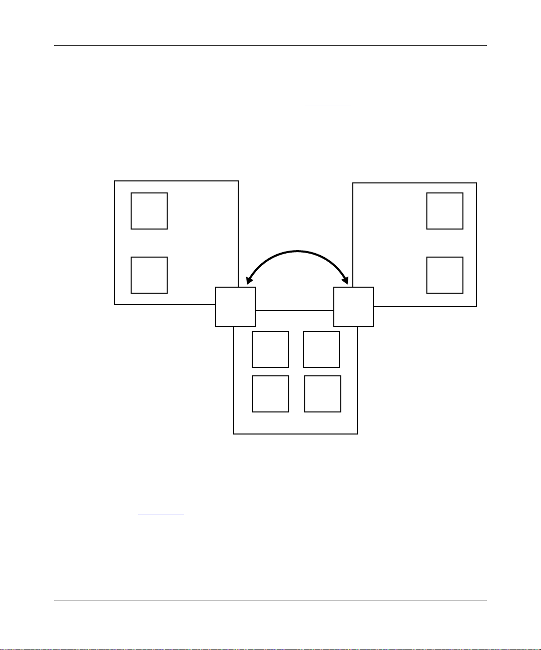
Static IPv4 Tunnel
A static tunnel -- also called a configured tunnel -- is a mechanism for forwarding
any IPv6 packet through an IPv4 region. F
an IPv4 interface on router C and an IPv4 interface on router D. (Note that routers
C and D are running both IPv4 and IPv6).
igure 1-4 shows a static tunnel between
IPv6
A
IPv6
B
Region 1
IPv6 IPv6
Configured
IPv6
C
IPv4
IPV4 tunnel
with end points
IPv4
G
IPv4
I
IPv4
Region 2
IPv4
H
IPv4
J
Region 3
IPv6
E
IPv6
F
IPv6
D
IPv4
IP0042A
Figure 1-4. Configured IPv4 Static Tunnel
In Figure 1-4, for example, a user connected to router B in Region 1 sends a
packet addressed to a user on router F in Region 3. The following steps occur:
1. Router C receives the IPv6 packet and determines that it must be forwarded
out its tunnel interface.
1-22 118428-A Rev. A
Page 23

2. Router C encapsulates the IPv6 packet in an IPv4 header.
The source address in the IPv4 header is the IPv4 address of the local tunnel
interface on router C. The destination address is the IPv4 address of the
remote tunnel interface on router D.
3. Using the IPv4 header, intermediate IPv4 routers in Region 2 forward the
encapsulated packet through the IPv4 region to router D.
4. Router D decapsulates the packet (removing the IPv4 header) and forwards
the original IPv6 packet to router F.
After you have configured the IPv4 interfaces on the end point routers, the tunnel
becomes a permanent point-to-point link in the IPv6 topology.
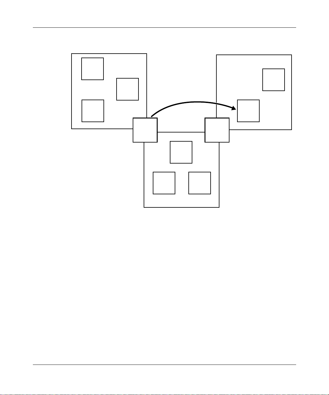
Automatic IPv4 Tunnel
An automatic tunnel is a mechanism for forwarding unicast IPv6 packets that use
the IPv4-compatible address format. All routers in IPv6 re gions that use automatic
tunneling must run both IPv6 and IPv4.
IPv6 creates the tunnel dynamically as needed for the purpose of forwarding an
IPv6 packet through multiple IPv4 and IPv4/IPv6 routers.
IPv6 Overview
igure 1-5, for example, a user connected to router B in Region 1 wants to send
In F
an IPv6 packet to a user on router J in Region 3.
118428-A Rev. A 1-23
Page 24
Configuring IPv6 Services
IPv6
A
IPv4
IPv6
B
IPv4
Region 1
IPv6
C
IPv4
IPv6/V4
IPv6
D
IPv4
Automatic
IPV4 tunnel
with end points
IPv4
F
IPv4
E
Region 2
IPv4
IPv4
G
IPv6
H
IPv4
Region 3
IPv6
J
IPv4
IPv6
I
IPv4
IPv6/V4
IP0041A
Figure 1-5. Automatic IPv4 Tunnel
The following steps occur:
1. Router D receives the packet and determines that the next hop requires an
automatic tunnel.
2. Router D encapsulates the packet in an IPv4 header.
The source address in the IPv4 header is the IPv4 address of the local tunnel
interface on node D.
The destination address is the IPv4 address contained in the IPv4-compatible
IPv6 address. This is the address of an IPv4 interface on router J.
3. IPv4 routers in Region 2 forward the packet to Region 3.
4. IPv4/ IPv6 router in Region 3 forward the IPv4 packet to router J.
1-24 118428-A Rev. A
Page 25

5. Router J decapsulates the packet.
Note that unlike a configured tunnel, which is a permanent point-to-point link in
the IPv6 topology, an automatic tunnel is a dynamic mechanism, created by the
encapsulating end point for the purpose forwarding an IPv6 packet. After the
packet reaches its destination, the automatic tunnel no longer exists.
Semiautomatic IPv4 Tunnel
A semiautomatic tunnel acts as a static tunnel for outgoing traffic and as an
automatic (multipoint-to-point) tunnel for incoming traffic.
IPv6 Tunnels
Like an IPv4 tunnel, an IPv6 tunnel can be a static tunnel, an automatic tunnel, or
a semiautomatic tunnel.
Packet Forwarding
IPv6 forwards
IPv6 Overview
• Unicast packets not addressed to itself.
• Packets with predefined multicast addresses.
• Packets addressed to itself that include a routing source extension header. The
extension header specifies a list of one or more intermediate nodes that define
a path for the packet to follow through the network to its destination.
IPv6 processes packets that are addressed to itself (with the exception of packets
that contain a routing option extension header). IPv6 recognizes the following
addresses as identifying itself:
• A unicast address assigned to the router
• A loopback address used by a node to send an IPv6 datagram to itself
• An all-nodes or all-hosts multicast address
• An anycast address assigned to the router
118428-A Rev. A 1-25
Page 26

Configuring IPv6 Services
IPv6 Extension Headers
IPv6 extension headers describe processing options. Each extension header
contains a separate category of options. A packet can include zero or more
extension headers (F
igure 1-6).
Datalink
header
Figure 1-6. IPV6 Header and Extension Headers
IPv6
header
Ipv6 extension
headers
•••
Upper-layer
headers
User data
IP0046A
IPv6 examines the destination address in the main header of each packet it
receives to determine whether the router is the packet’s destination or an
intermediate node in the packet’s data path.
• If the router is the destination of the packet, IPv6 examines the header
extensions that contain options for destination processing.
• If the router is an intermediate node, IPv6 e xamines the header extensions that
contain forwarding options.
By examining only the extension headers that apply to the operations it performs,
IPv6 reduces the amount of time and processing resources required to process a
packet.
IPv6 defines the following extension headers:
• The source routing extension header contains a list of one or more
intermediate nodes that define a path for the packet to follow through the
network to its destination. The packet source creates this list. This function is
similar to IPv4 source routing options.
• The fragmentation extension header is used by an IPv6 source to send packets
larger than the size specified for the path MTU.
• The authentication extension header and the security encapsulation extension
header, used singly or together, provide security services for IPv6 datagrams.
1-26 118428-A Rev. A
Page 27

• The hop-by-hop extension header contains optional information that must be
examined by all intermediate IPv6 routers between the source and the
destination.
• The end-to-end extension header contains optional information that must be
examined by the destination node.
Neighbor Discovery
Neighbor discovery (ND) allows IPv6 nodes on the same link to discover link
layer addresses and to obtain and advertise various network parameters and
reachability information. ND combines the services provided for IPv4 by the
Address Resolution Protocol (ARP) and router discovery.
Address Autoconfiguration
Typically, to start the process of autoconfiguration, a node
• Self-configures a link-local address to use temporarily. The host can form this
address by adding a generic local address prefix to a unique token (typically,
the host’s IEE LAN interface address).
IPv6 Overview
• Sends out an ND message to the address to ensure that it is unique. If no ND
message comes back, the address is unique. If a message comes back
indicating that the link-local address is already in use, the host uses a different
token (for example, an administrative token or a randomly generated token).
• Uses the IPv6 multicast service to send out an ND router solicitation request,
using the new link-local address as a source address. Unlike the broadcast
ARPs of IPv4, ND multicast solicitations are not necessarily processed by all
nodes on the link. IPv6 defines several permanent multicast groups for finding
resources on a local node or link, including an all-routers group, an all-hosts
group, and a Dynamic Host Configuration Protocol (DHCP) server group.
Routers respond to the solicitation messages from hosts with a unique router
advertisement that includes prefix information indicating a valid range of
addresses for the subnet. Routers can also send these advertisements periodically
to local multicast groups, whether or not they receive solicitations.
Using the router advertisement message that it sends in response to a solicitation
from a host, an IPv6 router can control whether the host uses stateful or stateless
autoconfiguration.
118428-A Rev. A 1-27
Page 28

Configuring IPv6 Services
In stateful autoconfiguration, the host contacts a DHCP or similar address server,
which assigns an address from a manually administered list.
In stateless autoconfiguration, a host can automatically configure its own IPv6
address without the help of a stateful address server. The host uses the globally
valid address prefix information in the router advertisement message to create its
own IPv6 address. The host concatenates the valid prefix with its link layer
address (or a similar unique token) to create an IPv6 address.
RIPv6
RIPv6 -- the Routing Information Protocol for IPv6 -- is a distance-vector
protocol that enables IPv6 routers in the same autonomous system to exchange
routing information by means of periodic RIP updates. Routers transmit their own
RIPv6 updates to neighboring networks and listen for RIPv6 updates from the
routers on those neighboring networks. Routers use the information in the RIPv6
updates to keep their internal routing tables current. For RIPv6, the “best” path to
a destination is the shortest path (the path with the fewest hops). RIPv6 computes
distance as a metric, usually the number of hops (or routers) from the origin
network to the target network.
RIPv6 is described in Cha
1-28 118428-A Rev. A
pter 4.
Page 29

Starting IPv6
Before you can choose a protocol to run on the router, you must configure a circuit
that the protocol can use as an interface to an attached network. For information
and instructions, see Configuring Ethernet, FDDI, and Token Ring Services or
Configuring WAN Line Services.
When you have successfully configured the circuit, the Select Protocols window
opens. Proceed as follows:
Chapter 2
Starting IPv6 Services
Site Manager Procedure
You do this System responds
1. In the Select Protocols window, choose
IPv6.
2. Click on OK to accept default values for
IPv6 parameters.
The Configure Interfaces window opens.
You return to the Configuration Manager
window.
IPv6 is now configured on this interface and slot with default values for all global
and interface parameters. You customize IPv6 by modifying IPv6 parameters as
described in Cha
118428-A Rev. A 2-1
pter 3.
Page 30

Configuring IPv6 Services
Adding Neighbor Discovery to an IPv6 Interface
Use Site Manager to add Neighbor Discovery to an IPv6 interface as follows.
Site Manager Procedure
You do this System responds
1. In the Configuration Manager window,
choose Protocols.
2. Choose IPv6. The IPv6 menu opens.
3. Choose Neighbor Discovery. The List IPv6 Neighbor Discovery window
4. Choose Add. The Values Selection window opens.
5. Choose the IPv6 interface to which you
want to add Neighbor Discovery, and click
on OK.
6. Click on Apply and Done to accept def ault
values for Neighbor Discovery
parameters.
To customize the Neighbor Discovery values, go to pa
Adding RIPv6 to an IPv6 Interface
Use Site Manager to add RIPv6 to an IPv6 interface as follows.
Site Manager Procedure
You do this System responds
1. In the Configuration Manager window,
choose Protocols.
2. Choose IPv6. The IPv6 menu opens.
3. Choose RIPv6 Interfaces. The RIPv6 Interfaces window opens.
4. Choose Add. The IPv6 Indexes window opens.
5. Choose the index value for the IPv6
interface to which you want to add RIPv6.
6. Click on Apply and Done to accept def ault
values for RIPv6 parameters.
The Protocols menu opens.
opens.
The Values Selection window closes and
the interface you chose appears in the
List IPv6 Neighbor Discovery window.
You return to the Configuration Manager
window.
ge 3-42.
The Protocols menu opens.
The RIPv6 Interfaces window reopens.
You return to the Configuration Manager
window.
To customize the RIPv6 values, go to Cha
pter 4.
2-2 118428-A Rev. A
Page 31

Chapter 3
Configuring and Customizing IPv6
You configure and customize IPv6 by setting IPv6 parameters as described under
the following topics:
Topic Page
Customizing IPv6 Globally 3-2
Customizing an IPv6 Interface 3-8
Configuring a Tunnel on the Interface 3-23
Configuring an IPv6 Address Prefix 3-31
Customizing IPv6 Neighbor Discovery 3-42
Defining an IPv6 Adjacent Node 3-54
Configuring an IPv6 Static Route 3-61
Configuring a Static Default Route 3-68
Configuring a Black Hole 3-68
118428-A Rev. A 3-1
Page 32

Configuring IPv6 Services
Customizing IPv6 Globally
When you configure an IPv6 interface, IPv6 runs on the router with default values
for all global parameters. You customize IPv6 on the router by modifying global
parameters as described under the following topics:
T opic Page
Enabling and Disabling Global IP 3-2
Configuring IPv6 in Not-Forwarding Mode 3-3
Supplying a Value for the Hop Limit Field 3-4
Specifying a Minimum Link MTU Size 3-5
Enabling and Disabling MTU Path Discovery 3-6
Specifying an MTU Path Timeout Period 3-7
Enabling and Disabling Global IP
By default, IPv6 is enabled on the router.
You can use the following Site Manager procedure to change the state as required.
Site Manager Procedure
You do this System responds
1. In the Configuration Manager window,
choose Protocols.
2. Choose IPv6. The IPv6 menu opens.
3. Choose IPv6 Global. The Edit IPv6 Global Parameters window
4. Set the Enable parameter. Click on Help
or see the parameter description on page
A-1.
5. Click on OK. Site Manager returns you to the
3-2 118428-A Rev. A
The Protocols menu opens.
opens.
Configuration Manager window.
Page 33

Configuring IPv6 in Not-Forwarding Mode
By default IPv6 forwards all packets that are not addressed to itself.
You can use the following Site Manager procedure to specify whether this entity is
acting as an IPv6 router in respect to the forwarding of datagrams. Ipv6 routers
forward received datagrams that are not addressed to itself. IPv6 hosts do not
forward datagrams (except those source-routed via the host).
Site Manager Procedure
You do this System responds
Configuring and Customizing IPv6
1. In the Configuration Manager window,
choose Protocols.
2. Choose IPv6. The IPv6 menu opens.
3. Choose IPv6 Global. The Edit IPv6 Global Parameters window
4. Set the Forwarding parameter. Click on
Help or see the parameter description on
page A-1.
5. Click on OK. Site Manager returns you to the
The Protocols menu opens.
opens.
Configuration Manager window.
118428-A Rev. A 3-3
Page 34

Configuring IPv6 Services
Supplying a Value for the Hop Limit Field
The IPv6 header includes a hop limit field set by the originating router (the source
node). Each intermediate node (that is, each node that receives and forwards the
packet) decrements the hop-limit value by one. When the hop-limit value
decrements to zero, the packet is discarded. (The IPv6 hop-limit value serves the
same function as the IPv4 time-to-live value.)
By default, IPv6 inserts a value of 64 into the Hop Limit field of the header of
datagrams originated at the router.
If the transport layer protocol supplies a hop-limit value, IPv6 uses that value.
You can use the following Site Manager procedure to specify a hop-limit value
from 0 to 255.
Site Manager Procedure
You do this System responds
1. In the Configuration Manager window,
choose Protocols.
2. Choose IPv6. The IPv6 menu opens.
3. Choose IPv6 Global. The Edit IPv6 Global Parameters window
4. Set the Default Hop parameter. Click on
Help or see the parameter description on
page A-2.
5. Click on OK. Site Manager returns you to the
The Protocols menu opens.
opens.
Configuration Manager window.
3-4 118428-A Rev. A
Page 35

Specifying a Minimum Link MTU Size
Each link in the IPv6 internet has a maximum transmission unit (MTU) size. The
MTU size is expressed in bytes.
IPv6 uses MTU path discovery to learn the MTU size used in the IPv6 internet.
(For instructions and information, see “Enabling and Disabling MTU Path
Discovery” on page 3-6.)
By default, if MTU path discovery is disabled, IPv6 generates packets with an
MTU size of 576 bytes.
By changing this parameter, you can control the maximum size of packets that can
be generated by this router if MTU path discovery is disabled.
You can use the following Site Manager procedure to specify a minimum link
MTU size from 296 to 65535 bytes.
Site Manager Procedure
You do this System responds
Configuring and Customizing IPv6
1. In the Configuration Manager window,
choose Protocols.
2. Choose IPv6. The IPv6 menu opens.
3. Choose IPv6 Global. The Edit IPv6 Global Parameters window
4. Set the Minimum Link MTU parameter.
Click on Help or see the parameter
description on page A-2.
5. Click on OK. Site Manager returns you to the
118428-A Rev. A 3-5
The Protocols menu opens.
opens.
Configuration Manager window.
Page 36

Configuring IPv6 Services
Enabling and Disabling MTU Path Discovery
Each link in the IPv6 internet has an MTU size, which is expressed in bytes.
By default IPv6 uses MTU path discovery to learn the MTU size for the IPv6
internet.
Disable this feature if you want to use the Minimum Link MTU parameter to
control the maximum size of self-generated packets.
You can use the following Site Manager procedure to enable and disable MTU
path discovery support for self-originated packets.
Site Manager Procedure
You do this System responds
1. In the Configuration Manager window,
choose Protocols.
2. Choose IPv6. The IPv6 menu opens.
3. Choose IPv6 Global. The Edit IPv6 Global Parameters window
4. Set the MTU Discovery parameter. Click
on Help or see the parameter description
on page A-2.
5. Click on OK. Site Manager returns you to the
The Protocols menu opens.
opens.
Configuration Manager window.
3-6 118428-A Rev. A
Page 37

Specifying an MTU Path Timeout Period
By default, a router that has learned a link MTU value through MTU path
discovery considers the value to be valid for 10 minutes.
You can use the following Site Manager procedure to specify a timeout period
from 1 minute to 71582788 minutes or to disable the feature (by specifying 0).
Site Manager Procedure
You do this System responds
Configuring and Customizing IPv6
1. In the Configuration Manager window,
choose Protocols.
2. Choose IPv6. The IPv6 menu opens.
3. Choose IPv6 Global. The Edit IPv6 Global Parameters window
4. Set the MTU Timeouts parameter. Click
on Help or see the parameter description
on page A-3.
5. Click on OK. Site Manager returns you to the
The Protocols menu opens.
opens.
Configuration Manager window.
118428-A Rev. A 3-7
Page 38

Configuring IPv6 Services
Customizing an IPv6 Interface
When you configure an IPv6 interface on a circuit, IPv6 runs with default values
for all interface parameters. You customize the IPv6 interface by modifying
parameters as described under the following topics:
Topic Page
Enabling and Disabling the Interface 3-9
Supplying a Description of the Interface 3-10
Supplying an Interface ID 3-11
Specifying the Circuit Name 3-12
Specifying the Link Layer Address 3-13
Specifying an MTU Size for the Link 3-14
Specifying the Size of the Forwarding Table 3-15
Configuring IPv6 on the Circuitless Interface 3-16
Enabling and Disabling Redirect Messages 3-17
Configuring ICMP Error Messages 3-18
Enabling and Disabling TR End Station Support 3-19
Specifying an SMDS Group Address 3-20
Specifying Frame Relay Broadcast DLCI 3-21
Specifying Frame Relay Multicast DLCI 3-22
3-8 118428-A Rev. A
Page 39

Enabling and Disabling the Interface
By default, IPv6 is enabled on the interface:
You can use the following Site Manager procedure to disable and reenable IPv6
on the interface as required.
Site Manager Procedure
You do this System responds
Configuring and Customizing IPv6
1. In the Configuration Manager window,
choose Protocols.
2. Choose IPv6. The IPv6 menu opens.
3. Choose Edit IPv6 Interfaces. The IPv6 Interfaces window opens.
4. Click on the interface you want to edit. Site Manager displays the parameter
5. Set the Enable parameter. Click on Help
or see the parameter description on page
A-3.
6. Click on Apply, and then click on Done. Site Manager returns you to the
The Protocols menu opens.
values for that interface.
Configuration Manager window.
118428-A Rev. A 3-9
Page 40

Configuring IPv6 Services
Supplying a Description of the Interface
You can use the following Site Manager procedure to enter a description of the
IPv6 interface from 1 to 255 characters.
Site Manager Procedure
You do this System responds
1. In the Configuration Manager window,
choose Protocols.
2. Choose IPv6. The IPv6 menu opens.
3. Choose Edit IPv6 Interfaces. The IPv6 Interfaces window opens.
4. Click on the interface you want to edit. Site Manager displays the parameter
5. Set the Interface Description parameter.
Click on Help or see the parameter
description on page A-3.
6. Click on Apply, and then click on Done. Site Manager returns you to the
The Protocols menu opens.
values for that interface.
Configuration Manager window.
3-10 118428-A Rev. A
Page 41

Supplying an Interface ID
The interface ID -- also called the token -- is a unique number identifying an IPv6
node (a host or a router). This ID is 64 bits long for stateless autoconfiguration.
In IPv6 stateless autoconfiguration, the interface ID is derived by a formula that
uses the link layer 48-bit MAC address. (In most cases, the interface ID is a 64-bit
number that contains the 48-bit MAC address.)
If you elect to configure interface tokens or MAC addresses (or both) manually,
there need not be any relation between the MAC address and the token. A
manually configured token may also be longer or shorter than 64 bits.
You can use the following Site Manager procedure to supply a different interface
ID from one to six characters.
You do this System responds
Configuring and Customizing IPv6
Site Manager Procedure
1. In the Configuration Manager window,
choose Protocols.
2. Choose IPv6. The IPv6 menu opens.
3. Choose Edit IPv6 Interfaces. The IPv6 Interfaces window opens.
4. Click on the interface you want to edit. Site Manager displays the parameter
5. Set the Interface Token parameter. Click
on Help or see the parameter description
on page A-4.
6. Click on Apply, and then click on Done. Site Manager returns you to the
The Protocols menu opens.
values for that interface.
Configuration Manager window.
118428-A Rev. A 3-11
Page 42

Configuring IPv6 Services
Specifying the Circuit Name
By default, IPv6 uses the circuit name you specified when you configured the
interface.
You can configure an interface as the circuitless interface or as a tunnel end point.
• To configure the interface as the circuitless interface, set this parameter with a
value greater than 1023 (the highest valid circuit number).
• To configure the interface as a tunnel end point, set this parameter to 0.
You can use the following Site Manager procedure to set the Circuit Name
parameter.
You do this System responds
Site Manager Procedure
1. In the Configuration Manager window,
choose Protocols.
2. Choose IPv6. The IPv6 menu opens.
3. Choose Edit IPv6 Interfaces. The IPv6 Interfaces window opens.
4. Click on the interface you want to edit. Site Manager displays the parameter
5. Set the Circuit Name parameter. Click on
Help or see the parameter description on
page A-4.
6. Click on Apply, and then click on Done. Site Manager returns you to the
The Protocols menu opens.
values for that interface.
Configuration Manager window.
3-12 118428-A Rev. A
Page 43

Specifying the Link Layer Address
By default, IPv6 uses the 48-bit MAC address of the interface on which this
interface is configured as the link layer address.
You can use the following Site Manager procedure to supply a link layer address.
Site Manager Procedure
You do this System responds
Configuring and Customizing IPv6
1. In the Configuration Manager window,
choose Protocols.
2. Choose IPv6. The IPv6 menu opens.
3. Choose Edit IPv6 Interfaces. The IPv6 Interfaces window opens.
4. Click on the interface you want to edit. Site Manager displays the parameter
5. Set the Link Layer Address parameter.
Click on Help or see the parameter
description on page A-4.
6. Click on Apply, and then click on Done. Site Manager returns you to the
The Protocols menu opens.
values for that interface.
Configuration Manager window.
118428-A Rev. A 3-13
Page 44

Configuring IPv6 Services
Specifying an MTU Size for the Link
By default, IPv6 uses the default MTU size for the underlying medium.
You can specify a different MTU size for the configured link from 0 to 65535.
IPv6 considers this value only if it is less than the default MTU of the underlying
medium.
Enter 0 if you want IPv6 to use the default MTU of the underlying medium.
You can use the following Site Manager procedure to perform this operation.
Site Manager Procedure
You do this System responds
1. In the Configuration Manager window,
choose Protocols.
2. Choose IPv6. The IPv6 menu opens.
3. Choose Edit IPv6 Interfaces. The IPv6 Interfaces window opens.
4. Click on the interface you want to edit. Site Manager displays the parameter
5. Set the Link MTU parameter. Click on
Help or see the parameter description on
page A-5.
6. Click on Apply, and then click on Done. Site Manager returns you to the
The Protocols menu opens.
values for that interface.
Configuration Manager window.
3-14 118428-A Rev. A
Page 45

Specifying the Size of the Forwarding Table
By default, IPv6 allows a maximum of 128 entries in the interface forwarding
table (also called the cache) at one time. There is a forwarding table for each
interface.
You can use the following Site Manager procedure to configure a forwarding table
for 0 to 20480 entries.
Site Manager Procedure
You do this System responds
Configuring and Customizing IPv6
1. In the Configuration Manager window,
choose Protocols.
2. Choose IPv6. The IPv6 menu opens.
3. Choose Edit IPv6 Interfaces. The IPv6 Interfaces window opens.
4. Click on the interface you want to edit. Site Manager displays the parameter
5. Set the Cache Size parameter. Click on
Help or see the parameter description on
page A-5.
6. Click on Apply, and then click on Done. Site Manager returns you to the
The Protocols menu opens.
values for that interface.
Configuration Manager window.
118428-A Rev. A 3-15
Page 46

Configuring IPv6 Services
Configuring IPv6 on the Circuitless Interface
If you want to configure IPv6 on the circuitless interface, you must set the circuit
number to a value greater than 1023.
You can use the following Site Manager procedure to specify a slot or indicate
acceptable slots for the circuitless interface.
Site Manager Procedure
You do this System responds
1. In the Configuration Manager window,
choose Protocols.
2. Choose IPv6. The IPv6 menu opens.
3. Choose Edit IPv6 Interfaces. The IPv6 Interfaces window opens.
4. Click on the interface you want to edit. Site Manager displays the parameter
5. Set the Slot Mask parameter. Click on
Help or see the parameter description on
page A-5.
6. Click on Apply, and then click on Done. Site Manager returns you to the
The Protocols menu opens.
values for that interface.
Configuration Manager window.
3-16 118428-A Rev. A
Page 47

Enabling and Disabling Redirect Messages
By default, IPv6 sends Internet Control Message Protocol (ICMP) redirect
messages on this interface.
You can use the following Site Manager procedure to disable and reenable redirect
messages on the IPv6 interface.
Site Manager Procedure
You do this System responds
Configuring and Customizing IPv6
1. In the Configuration Manager window,
choose Protocols.
2. Choose IPv6. The IPv6 menu opens.
3. Choose Edit IPv6 Interfaces. The IPv6 Interfaces window opens.
4. Click on the interface you want to edit. Site Manager displays the parameter
5. Set the Redirect On/Off parameter. Click
on Help or see the parameter description
on page A-6.
6. Click on Apply, and then click on Done. Site Manager returns you to the
The Protocols menu opens.
values for that interface.
Configuration Manager window.
118428-A Rev. A 3-17
Page 48

Configuring IPv6 Services
Configuring ICMP Error Messages
By default, IPv6 is allowed to transmit up to 100 ICMP error messages per second
on this interface.
You can use the following Site Manager procedure to supply a different maximum
number.
Site Manager Procedure
You do this System responds
1. In the Configuration Manager window,
choose Protocols.
2. Choose IPv6. The IPv6 menu opens.
3. Choose Edit IPv6 Interfaces. The IPv6 Interfaces window opens.
4. Click on the interface you want to edit. Site Manager displays the parameter
5. Set the Max ICMP Messages parameter.
Click on Help or see the parameter
description on page A-6.
6. Click on Apply, and then click on Done. Site Manager returns you to the
The Protocols menu opens.
values for that interface.
Configuration Manager window.
3-18 118428-A Rev. A
Page 49

Configuring and Customizing IPv6
Enabling and Disabling TR End Station Support
By default, IPv6 does not provide source routing support for a token ring network.
If the interface is connected to a token ring network, you can use the following
Site Manager procedure to enable TR end station support.
Site Manager Procedure
You do this System responds
1. In the Configuration Manager window,
choose Protocols.
2. Choose IPv6. The IPv6 menu opens.
3. Choose Edit IPv6 Interfaces. The IPv6 Interfaces window opens.
4. Click on the interface you want to edit. Site Manager displays the parameter
5. Set the TR End Station parameter. Click
on Help or see the parameter description
on page A-6.
6. Click on Apply, and then click on Done. Site Manager returns you to the
The Protocols menu opens.
values for that interface.
Configuration Manager window.
118428-A Rev. A 3-19
Page 50

Configuring IPv6 Services
Specifying an SMDS Group Address
You can use the following Site Manager procedure to provide a switched
multimegabit data service (SMDS) group address for this interface.
Site Manager Procedure
You do this System responds
1. In the Configuration Manager window,
choose Protocols.
2. Choose IPv6. The IPv6 menu opens.
3. Choose Edit IPv6 Interfaces. The IPv6 Interfaces window opens.
4. Click on the interface you want to edit. Site Manager displays the parameter
5. Set the SMDS Group Address parameter .
Click on Help or see the parameter
description on page A-7.
6. Click on Apply, and then click on Done. Site Manager returns you to the
The Protocols menu opens.
values for that interface.
Configuration Manager window.
3-20 118428-A Rev. A
Page 51

Specifying Frame Relay Broadcast DLCI
You can use the following Site Manager procedure to supply a frame relay
broadcast data link connection identifier (DLCI).
Site Manager Procedure
You do this System responds
Configuring and Customizing IPv6
1. In the Configuration Manager window,
choose Protocols.
2. Choose IPv6. The IPv6 menu opens.
3. Choose Edit IPv6 Interfaces. The IPv6 Interfaces window opens.
4. Click on the interface you want to edit. Site Manager displays the parameter
5. Set the Frame Relay Broadcast DLCI
parameter. Click on Help or see the
parameter description on page A-7.
6. Click on Apply, and then click on Done. Site Manager returns you to the
The Protocols menu opens.
values for that interface.
Configuration Manager window.
118428-A Rev. A 3-21
Page 52

Configuring IPv6 Services
Specifying Frame Relay Multicast DLCI
You can use the following Site Manager procedure to supply frame relay multicast
DLCI numbers 1 and 2.
Site Manager Procedure
You do this System responds
1. In the Configuration Manager window,
choose Protocols.
2. Choose IPv6. The IPv6 menu opens.
3. Choose Edit IPv6 Interfaces. The IPv6 Interfaces window opens.
4. Click on the interface you want to edit. Site Manager displays the parameter
5. Set the following parameters:
• Frame Relay Multicast DLCI #1
• Frame Relay Multicast DLCI #2
Click on Help or see the parameter
descriptions beginning on page A-7.
6. Click on Apply, and then click on Done. Site Manager returns you to the
The Protocols menu opens.
values for that interface.
Configuration Manager window.
3-22 118428-A Rev. A
Page 53

Configuring a Tunnel on the Interface
For an overview of tunnels and information about the types of tunnels you can
configure on an IPv6 interface, see “Tunnels” on page 1-21.
To configure a tunnel on this interface,
1. Configure the IPv6 interface as a tunnel end point.
2. Specify the type of type of tunnel you want to configure.
3. Supply the local and remote end point addresses required for the type of
tunnel you are configuring.
These operations are described under the following topics:
Topic Page
Configuring an IPv6 Interface as a Tunnel End Point 3-24
Specifying a Tunnel Type 3-25
Specifying a Local IPv4 Address 3-27
Specifying a Remote IPv4 Address 3-28
Specifying a Local IPv6 Index 3-29
Specifying a Remote IPv6 Address 3-30
Configuring and Customizing IPv6
118428-A Rev. A 3-23
Page 54

Configuring IPv6 Services
Configuring an IPv6 Interface as a Tunnel End Point
To indicate that the interface is the end point of a tunnel, use the following Site
Manager procedure to enter a circuit number of 0.
Site Manager Procedure
You do this System responds
1. In the Configuration Manager window,
choose Protocols.
2. Choose IPv6. The IPv6 menu opens.
3. Choose Edit IPv6 Interfaces. The IPv6 Interfaces window opens.
4. Click on the interface you want to edit. Site Manager displays the parameter
5. Set the Circuit Name parameter with the
value 0.
6. Click on Apply, and then click on Done. Site Manager returns you to the
The Protocols menu opens.
values for that interface.
Configuration Manager window.
3-24 118428-A Rev. A
Page 55

Specifying a Tunnel Type
For information about IPv6 and IPv4 tunnel types, see “Tunnels” on page 1-21.
IPv6 supports the following types of tunnels:
• IPv4 static tunnel. If you specify an IPv4 static tunnel, you must supply an
IPv4 address for the local and remote end point.
• IPv4 automatic tunnel. If you specify an IPv4 automatic tunnel, you must
supply an IPv4 address for the local end point.
• IPv4 semiautomatic tunnel. If you specify an IPv4 semiautomatic tunnel, you
must supply an IPv4 address for the local and remote end points.
• IPv6 static tunnel. If you specify an IPv6 static tunnel, you must supply an
IPv6 index number for the local end point and supply an IPv6 address for
remote end point.
• IPv6 automatic tunnel. If you specify an IPv6 automatic tunnel, you must
supply an IPv6 address for the local end point.
• IPv6 semiautomatic tunnel. If you specify an IPv6 semiautomatic tunnel, you
must supply an IPv6 index number for the local end point and supply an IPv6
address for the remote end point.
Configuring and Customizing IPv6
118428-A Rev. A 3-25
Page 56

Configuring IPv6 Services
You can use the following Site Manager procedure to specify the type of tunnel
you want you want to configure on the interface.
You do this System responds
Site Manager Procedure
1. In the Configuration Manager window,
choose Protocols.
2. Choose IPv6. The IPv6 menu opens.
3. Choose Edit IPv6 Interfaces. The IPv6 Interfaces window opens.
4. Click on the interface you want to edit. Site Manager displays the parameter
5. Set the Tunnel Protocol Type parameter.
Click on Help or see the parameter
description on page A-8.
6. Click on Apply, and then click on Done. Site Manager returns you to the
The Protocols menu opens.
values for that interface.
Configuration Manager window.
3-26 118428-A Rev. A
Page 57

Specifying a Local IPv4 Address
If you are configuring an IPv4 static tunnel, an IPv4 automatic tunnel, or an IPv4
semiautomatic tunnel, you must supply the IP address of the local IPv4 end point.
This address becomes the source address in the encapsulating IPv4 header.
You can use the following Site Manager procedure to specify a local IPv4 address.
You do this System responds
Configuring and Customizing IPv6
Site Manager Procedure
1. In the Configuration Manager window,
choose Protocols.
2. Choose IPv6. The IPv6 menu opens.
3. Choose Edit IPv6 Interfaces. The IPv6 Interfaces window opens.
4. Click on the interface you want to edit. Site Manager displays the parameter
5. Set the Tunnel IPv4 Local Address
parameter. Click on Help or see the
parameter description on page A-9.
6. Click on Apply, and then click on Done. Site Manager returns you to the
The Protocols menu opens.
values for that interface.
Configuration Manager window.
118428-A Rev. A 3-27
Page 58

Configuring IPv6 Services
Specifying a Remote IPv4 Address
If you are configuring an IPv4 static tunnel or an IPv4 semiautomatic tunnel, you
must supply a remote IPv4 address.
For a static tunnel and a semiautomatic tunnel, this address becomes the
destination address in the encapsulating IPv4 header.
You can use the following Site Manager procedure to perform this operation.
Site Manager Procedure
You do this System responds
1. In the Configuration Manager window,
choose Protocols.
2. Choose IPv6. The IPv6 menu opens.
3. Choose Edit IPv6 Interfaces. The IPv6 Interfaces window opens.
4. Click on the interface you want to edit. Site Manager displays the parameter
5. Set the Tunnel IPv4 Remote Address
parameter. Click on Help or see the
parameter description on page A-9.
6. Click on Apply, and then click on Done. Site Manager returns you to the
The Protocols menu opens.
values for that interface.
Configuration Manager window.
3-28 118428-A Rev. A
Page 59

Specifying a Local IPv6 Index
If you are configuring an IPv6 static tunnel, an IPv6 automatic tunnel, or an IPv6
semiautomatic tunnel, you must supply the IPv6 index of the local IPv6 end point.
This index is used to create the source address in the encapsulating IPv6 header.
You can use the following Site Manager procedure to supply a local IPv6 index.
You do this System responds
Configuring and Customizing IPv6
Site Manager Procedure
1. In the Configuration Manager window,
choose Protocols.
2. Choose IPv6. The IPv6 menu opens.
3. Choose Edit IPv6 Interfaces. The IPv6 Interfaces window opens.
4. Click on the interface you want to edit. Site Manager displays the parameter
5. Set the IPv6 Local Index parameter. Click
on Help or see the parameter description
on page A-10.
6. Click on Apply, and then click on Done. Site Manager returns you to the
The Protocols menu opens.
values for that interface.
Configuration Manager window.
118428-A Rev. A 3-29
Page 60

Configuring IPv6 Services
Specifying a Remote IPv6 Address
If you are configuring an IPv6 static tunnel or an IPv6 semiautomatic tunnel, you
must supply a remote IPv6 address.
For a static tunnel and a semiautomatic tunnel, this address becomes the
destination address in the encapsulating IPv6 header.
You can use the following Site Manager procedure to supply a remote IPv6
address.
Site Manager Procedure
You do this System responds
1. In the Configuration Manager window,
choose Protocols.
2. Choose IPv6. The IPv6 menu opens.
3. Choose Edit IPv6 Interfaces. The IPv6 Interfaces window opens.
4. Click on the interface you want to edit. Site Manager displays the parameter
5. Set the Tunnel IPv6 Remote Address
parameter. Click on Help or see the
parameter description on page A-10.
6. Click on Apply, and then click on Done. Site Manager returns you to the
The Protocols menu opens.
values for that interface.
Configuration Manager window.
3-30 118428-A Rev. A
Page 61

Configuring an IPv6 Address Prefix
An IPv6 address consists of an interface ID and an address prefix. For information
about IPv6 addresses, see Chapter 1.
You configure an IPv6 address prefix by setting parameters as described under the
following topics:
Section Page
Associating a Prefix with an interface ID 3-32
Enabling and Disabling Use of the Prefix 3-33
Supplying an Address Prefix 3-34
Specifying the Length of the Prefix 3-35
Specifying a Routing Preference 3-36
Specifying a Cost 3-37
Configuring the Prefix for On-Link Determination 3-38
Enabling Autonomous Address Configuration 3-39
Supplying a Preferred Lifetime Value 3-40
Supplying a Valid Lifetime Value 3-41
Configuring and Customizing IPv6
118428-A Rev. A 3-31
Page 62

Configuring IPv6 Services
Associating a Prefix with an interface ID
You can use following Site Manager procedure to add an address prefix to an
interface ID to create a complete IPv6 address.
Site Manager Procedure
You do this System responds
1. In the Configuration Manager window,
choose Protocols.
2. Choose IPv6. The IPv6 menu opens.
3. Choose List Prefixes. The IPv6 Prefixes window opens.
4. Click on Add. The Values Selection window opens.
5. Choose the IPv6 index of the interface to
which you want to add the prefix.
6. Click on Apply, and then click on Done. Site Manager returns you to the
The Protocols menu opens.
The IPv6 Prefixes window reopens.
Configuration Manager window.
3-32 118428-A Rev. A
Page 63

Enabling and Disabling Use of the Prefix
By default, an address prefix you configure is enabled for use.
You can use the following Site Manager procedure to disable and reenable the
prefix.
Site Manager Procedure
You do this System responds
Configuring and Customizing IPv6
1. In the Configuration Manager window,
choose Protocols.
2. Choose IPv6. The IPv6 menu opens.
3. Choose List Prefixes. The IPv6 Prefixes window opens.
4. Set the Enable parameter. Click on Help
or see the parameter description on page
A-11.
5. Click on Apply, and then click on Done. Site Manager returns you to the
The Protocols menu opens.
Configuration Manager window.
118428-A Rev. A 3-33
Page 64

Configuring IPv6 Services
Supplying an Address Prefix
You can use the following Site Manager procedure to supply the address prefix.
You do this System responds
Site Manager Procedure
1. In the Configuration Manager window,
choose Protocols.
2. Choose IPv6. The IPv6 menu opens.
3. Choose List Prefixes. The IPv6 Prefixes window opens.
4. Set the Interface Prefix parameter. Click
on Help or see the parameter description
on page A-11.
5. Click on Apply, and then click on Done. Site Manager returns you to the
The Protocols menu opens.
Configuration Manager window.
3-34 118428-A Rev. A
Page 65

Specifying the Length of the Prefix
An address prefix can be 3 to 128 bits long.
You can use the following Site Manager procedure to specify the length of this
address prefix.
Site Manager Procedure
You do this System responds
Configuring and Customizing IPv6
1. In the Configuration Manager window,
choose Protocols.
2. Choose IPv6. The IPv6 menu opens.
3. Choose List Prefixes. The IPv6 Prefixes window opens.
4. Set the Prefix Length parameter . Click on
Help or see the parameter description on
page A-11.
5. Click on Apply, and then click on Done. Site Manager returns you to the
The Protocols menu opens.
Configuration Manager window.
118428-A Rev. A 3-35
Page 66

Configuring IPv6 Services
Specifying a Routing Preference
The default routing preference value is 15 (most preferred).
You can use the following Site Manager procedure to specify a routing preference
value from 1 to 15.
You do this System responds
Site Manager Procedure
1. In the Configuration Manager window,
choose Protocols.
2. Choose IPv6. The IPv6 menu opens.
3. Choose List Prefixes. The IPv6 Prefixes window opens.
4. Set the Routing Preference parameter.
Click on Help or see the parameter
description on page A-12.
5. Click on Apply, and then click on Done. Site Manager returns you to the
The Protocols menu opens.
Configuration Manager window.
3-36 118428-A Rev. A
Page 67

Specifying a Cost
The default cost of an address prefix is 1.
You can use the following Site Manager procedure to specify a cost from 1 to 15.
You do this System responds
Configuring and Customizing IPv6
Site Manager Procedure
1. In the Configuration Manager window,
choose Protocols.
2. Choose IPv6. The IPv6 menu opens.
3. Choose List Prefixes. The IPv6 Prefixes window opens.
4. Set the Prefix Cost parameter. Click on
Help or see the parameter description on
page A-12.
5. Click on Apply, and then click on Done. Site Manager returns you to the
The Protocols menu opens.
Configuration Manager window.
118428-A Rev. A 3-37
Page 68

Configuring IPv6 Services
Configuring the Prefix for On-Link Determination
By default, an address prefix can be used for on-link determination.
You can use the following Site Manager procedure to disable and reenable this
feature.
Site Manager Procedure
You do this System responds
1. In the Configuration Manager window,
choose Protocols.
2. Choose IPv6. The IPv6 menu opens.
3. Choose List Prefixes. The IPv6 Prefixes window opens.
4. Set the On Link Flag parameter. Click on
Help or see the parameter description on
page A-12.
5. Click on Apply, and then click on Done. Site Manager returns you to the
The Protocols menu opens.
Configuration Manager window.
3-38 118428-A Rev. A
Page 69

Enabling Autonomous Address Configuration
By default, this prefix can be used for autonomous address configuration -- that is,
to form a local interface address.
You can use the following Site Manager procedure to disable and reenable this
feature.
Site Manager Procedure
You do this System responds
Configuring and Customizing IPv6
1. In the Configuration Manager window,
choose Protocols.
2. Choose IPv6. The IPv6 menu opens.
3. Choose List Prefixes. The IPv6 Prefixes window opens.
4. Set the Autonomous Prefix Flag
parameter. Click on Help or see the
parameter description on page A-13.
5. Click on Apply, and then click on Done. Site Manager returns you to the
The Protocols menu opens.
Configuration Manager window.
118428-A Rev. A 3-39
Page 70

Configuring IPv6 Services
Supplying a Preferred Lifetime Value
The referred lifetime value indicates the length of time in seconds (relative to the
time the router advertisement is sent) that this prefix will remain preferred -- that
is, the time until deprecation.
The default lifetime, 0xffffffff (-1), represents infinity.
IPv6 places this value in the preferred lifetime field in the prefix information
option of a router advertisement.
When the preferred lifetime expires, the address generated from a deprecated
prefix should no longer be used as a source address in new communications.
However, packets received on such an interface are processed as expected.
You can use the following Site Manager procedure to supply a preferred lifetime
value.
Site Manager Procedure
You do this System responds
1. In the Configuration Manager window,
choose Protocols.
2. Choose IPv6. The IPv6 menu opens.
3. Choose List Prefixes. The IPv6 Prefixes window opens.
4. Set the Relative Preferred Lifetime
parameter. Click on Help or see the
parameter description on page A-13.
5. Click on Apply, and then click on Done. Site Manager returns you to the
3-40 118428-A Rev. A
The Protocols menu opens.
Configuration Manager window.
Page 71

Supplying a Valid Lifetime Value
The valid lifetime value indicates the length of time in seconds (relative to the
time the router advertisement is sent) that this prefix remains valid.
The default lifetime, 0xffffffff (-1), represents infinity.
IPv6 places this value in the valid lifetime field in the prefix information option of
router advertisements.
The address generated from an invalidated prefix should not appear as the
destination or source address of a packet.
You can use the following Site Manager procedure to supply a valid lifetime
value.
You do this System responds
Configuring and Customizing IPv6
Site Manager Procedure
1. In the Configuration Manager window,
choose Protocols.
2. Choose IPv6. The IPv6 menu opens.
3. Choose List Prefixes. The IPv6 Prefixes window opens.
4. Set the Relative Valid Lifetime
parameter. Click on Help or see the
parameter description on page A-14.
5. Click on Apply, and then click on Done. Site Manager returns you to the
The Protocols menu opens.
Configuration Manager window.
118428-A Rev. A 3-41
Page 72

Configuring IPv6 Services
Customizing IPv6 Neighbor Discovery
For an overview, see “Neighbor Discovery” on page 1-27.
When you configure IPv6 on an interface, neighbor discovery is automatically
added to the interface. You customize neighbor discovery by modifying neighbor
discovery parameters as described under the following topics:
Topic Page
Enabling and Disabling Neighbor Discovery 3-43
Controlling Router Advertisements 3-44
Controlling Address Autoconfiguration 3-45
Controlling Nonaddress Autoconfiguration 3-46
Specifying a Neighbor Reachability Time 3-47
Specifying a Retransmission Time For Neighbor Solicitations 3-48
Specifying a Maximum Hop Limit for ND Advertisements 3-49
Specifying a Minimum Time for Unsolicited Advertisements 3-50
Specifying a Maximum Time for Unsolicited Advertisements 3-51
Specifying a Lifetime for the Default Router 3-52
Configuring Address Duplication Detection 3-53
3-42 118428-A Rev. A
Page 73

Enabling and Disabling Neighbor Discovery
By default, neighbor discovery is enabled on the interface.
You can use the following Site Manager procedure to change the state of neighbor
discovery as required.
Site Manager Procedure
You do this System responds
Configuring and Customizing IPv6
1. In the Configuration Manager window,
choose Protocols.
2. Choose IPv6. The IPv6 menu opens.
3. Choose List Neighbor Discovery. The IPv6 Neighbor Discovery window
4. Set the Enable parameter. Click on Help
or see the parameter description on page
A-14.
5. Click on Apply, and then click on Done. Site Manager returns you to the
The Protocols menu opens.
opens.
Configuration Manager window.
118428-A Rev. A 3-43
Page 74

Configuring IPv6 Services
Controlling Router Advertisements
An IPv6 router receives ND solicitations messages from hosts on local networks.
The router responds by returning a unicast route advertisement message.
In addition to these responses, an IPv6 router can also send router advertisements
periodically on the interface to local multicast groups, whether or not they receive
solicitations.
You can use the following Site Manager procedure to control whether or not IPv6
sends periodic route advertisements on the interface.
Site Manager Procedure
You do this System responds
1. In the Configuration Manager window,
choose Protocols.
2. Choose IPv6. The IPv6 menu opens.
3. Choose List Neighbor Discovery. The IPv6 Neighbor Discovery window
4. Set the Router Advertisement
parameter. Click on Help or see the
parameter description on page A-14.
5. Click on Apply, and then click on Done. Site Manager returns you to the
The Protocols menu opens.
opens.
Configuration Manager window.
3-44 118428-A Rev. A
Page 75

Controlling Address Autoconfiguration
Using the router advertisement that it sends in response to a solicitation message
from a host, an IPv6 router can control whether the host uses stateful or stateless
autoconfiguration.
By default, the router instructs the host to use stateless autoconfiguration.
The following Site Manager procedure lets you configure IPv6 to instruct hosts to
use the administered (stateful) protocol for address autoconfiguration in addition
to any addresses autoconfigured using stateless address autoconfiguration.
Site Manager Procedure
You do this System responds
Configuring and Customizing IPv6
1. In the Configuration Manager window,
choose Protocols.
2. Choose IPv6. The IPv6 menu opens.
3. Choose List Neighbor Discovery. The IPv6 Neighbor Discovery window
4. Set the Managed Address Configuration
parameter. Click on Help or see the
parameter description on page A-15.
5. Click on Apply, and then click on Done. Site Manager returns you to the
The Protocols menu opens.
opens.
Configuration Manager window.
118428-A Rev. A 3-45
Page 76

Configuring IPv6 Services
Controlling Nonaddress Autoconfiguration
Turn the Managed Non-Address flag on if you want hosts to use the administered
(stateful) protocol for autoconfiguration of nonaddress information.
You can use the following Site Manager procedure to set the nonaddress flag as
required.
Site Manager Procedure
You do this System responds
1. In the Configuration Manager window,
choose Protocols.
2. Choose IPv6. The IPv6 menu opens.
3. Choose List Neighbor Discovery. The IPv6 Neighbor Discovery window
4. Set the Managed Non-Address
parameter. Click on Help or see the
parameter description on page A-15.
5. Click on Apply, and then click on Done. Site Manager returns you to the
The Protocols menu opens.
opens.
Configuration Manager window.
3-46 118428-A Rev. A
Page 77

Specifying a Neighbor Reachability Time
The neighbor reachability time is the number of milliseconds (ms) that a node
assumes a neighbor is reachable after having receiv ed a reachability confirmation.
By default, the router does not specify a reachability time (indicated by a value
of 0).
You can use the following Site Manager procedure to specify a neighbor
reachability time.
Site Manager Procedure
You do this System responds
Configuring and Customizing IPv6
1. In the Configuration Manager window,
choose Protocols.
2. Choose IPv6. The IPv6 menu opens.
3. Choose List Neighbor Discovery. The IPv6 Neighbor Discovery window
4. Set the Reachable Time parameter. Click
on Help or see the parameter description
on page A-15.
5. Click on Apply, and then click on Done. Site Manager returns you to the
The Protocols menu opens.
opens.
Configuration Manager window.
118428-A Rev. A 3-47
Page 78

Configuring IPv6 Services
Specifying a Retransmission Time For Neighbor Solicitations
The retransmission time for neighbor solicitations is the number of milliseconds
between retransmitted neighbor solicitation messages.
The default value is 0, indicating that the retransmission time is unspecified (by
this router).
You can use the following Site Manager procedure to specify a retransmission
time for neighbor solicitations.
Site Manager Procedure
You do this System responds
1. In the Configuration Manager window,
choose Protocols.
2. Choose IPv6. The IPv6 menu opens.
3. Choose List Neighbor Discovery. The IPv6 Neighbor Discovery window
4. Set the Retransmission Time parameter.
Click on Help or see the parameter
description on page A-16.
5. Click on Apply, and then click on Done. Site Manager returns you to the
The Protocols menu opens.
opens.
Configuration Manager window.
3-48 118428-A Rev. A
Page 79

Configuring and Customizing IPv6
Specifying a Maximum Hop Limit for ND Advertisements
The default maximum hop limit for ND advertisements is 64 hops.
You can use the following Site Manager procedure to specify a maximum hop
limit from 0 to 255 hops
You do this System responds
.
Site Manager Procedure
1. In the Configuration Manager window,
choose Protocols.
2. Choose IPv6. The IPv6 menu opens.
3. Choose List Neighbor Discovery. The IPv6 Neighbor Discovery window
4. Set the Maximum Hop Limit parameter.
Click on Help or see the parameter
description on page A-16.
5. Click on Apply, and then click on Done. Site Manager returns you to the
The Protocols menu opens.
opens.
Configuration Manager window.
118428-A Rev. A 3-49
Page 80

Configuring IPv6 Services
Specifying a Minimum Time for Unsolicited Advertisements
The minimum time for unsolicited advertisements is the minimum rate (in
seconds) at which the router can send unsolicited multicast router advertisements
on this interface.
The default minimum time is 200 seconds. The allowable range is 3 to 1350
seconds.
You can use the following Site Manager procedure to specify a minimum time for
unsolicited advertisements.
Site Manager Procedure
You do this System responds
1. In the Configuration Manager window,
choose Protocols.
2. Choose IPv6. The IPv6 menu opens.
3. Choose List Neighbor Discovery. The IPv6 Neighbor Discovery window
4. Set the Minimum Multicast parameter.
Click on Help or see the parameter
description on page A-16.
5. Click on Apply, and then click on Done. Site Manager returns you to the
The Protocols menu opens.
opens.
Configuration Manager window.
3-50 118428-A Rev. A
Page 81

Configuring and Customizing IPv6
Specifying a Maximum Time for Unsolicited Advertisements
The maximum time for unsolicited advertisements is the maximum rate (in
seconds) at which the router can send unsolicited multicast router advertisements
on this interface.
The default maximum time is 600 seconds. The allowable range is 4 to 1800
seconds.
You can use the following Site Manager procedure to set the maximum time for
unsolicited advertisements.
Site Manager Procedure
You do this System responds
1. In the Configuration Manager window,
choose Protocols.
2. Choose IPv6. The IPv6 menu opens.
3. Choose List Neighbor Discovery. The IPv6 Neighbor Discovery window
4. Set the Maximum Multicast parameter.
Click on Help or see the parameter
description on page A-17.
5. Click on Apply, and then click on Done. Site Manager returns you to the
The Protocols menu opens.
opens.
Configuration Manager window.
118428-A Rev. A 3-51
Page 82

Configuring IPv6 Services
Specifying a Lifetime for the Default Router
By default, the default router has a lifetime of 1800 seconds. The allowable
lifetime range is 0 to 9000 seconds.
You can use the following Site Manager procedure to specify a lifetime for the
default router.
Site Manager Procedure
You do this System responds
1. In the Configuration Manager window,
choose Protocols.
2. Choose IPv6. The IPv6 menu opens.
3. Choose List Neighbor Discovery. The IPv6 Neighbor Discovery window
4. Set the Default Lifetime parameter. Click
on Help or see the parameter description
on page A-17.
5. Click on Apply, and then click on Done. Site Manager returns you to the
The Protocols menu opens.
opens.
Configuration Manager window.
3-52 118428-A Rev. A
Page 83

Configuring Address Duplication Detection
By default, the router sends a single neighbor solicitation message (with no
follow-up retransmission) while performing duplicate address detection on a
tentative address.
You can use the following Site Manager procedure to supply a value from 0 to 10,
where 0 indicates that no duplicate address detection needs to be performed.
Site Manager Procedure
You do this System responds
Configuring and Customizing IPv6
1. In the Configuration Manager window,
choose Protocols.
2. Choose IPv6. The IPv6 menu opens.
3. Choose List Neighbor Discovery. The IPv6 Neighbor Discovery window
4. Set the Duplicate Address Detection
parameter. Click on Help or see the
parameter description on page A-17.
5. Click on Apply, and then click on Done. Site Manager returns you to the
The Protocols menu opens.
opens.
Configuration Manager window.
118428-A Rev. A 3-53
Page 84

Configuring IPv6 Services
Defining an IPv6 Adjacent Node
An adjacent node is a device attached to a local network. You define an adjacent
node by supplying information and setting values as described under the
following topics:
Topic Page
Enabling and Disabling the Adjacent Node Definition 3-55
Supplying the Physical Address of the Adjacent Node 3-56
Specifying the Link Layer Encapsulation Type 3-57
Specifying a Route Preference Value 3-58
Specifying the Cost 3-59
Supplying the WAN Address of the Adjacent Node 3-60
3-54 118428-A Rev. A
Page 85

Configuring and Customizing IPv6
Enabling and Disabling the Adjacent Node Definition
By default, the adjacent node definition that you are creating is enabled on the
router.
You can use the following Site Manager procedure to disable and reenable the
adjacent node definition as required.
Site Manager Procedure
You do this System responds
1. In the Configuration Manager window,
choose Protocols.
2. Choose IPv6. The IPv6 menu opens.
3. Choose List Adjacent Nodes. The IPv6 Adjacent Nodes window opens.
4. Set the Enable parameter. Click on Help
or see the parameter description on page
A-18.
5. Click on Apply, and then click on Done. Site Manager returns you to the
The Protocols menu opens.
Configuration Manager window.
118428-A Rev. A 3-55
Page 86

Configuring IPv6 Services
Supplying the Physical Address of the Adjacent Node
For a frame relay PVC, the physical address of the adjacent node is a 32-bit DLCI.
For an ATM PVC this address is a 32-bit VCID which has circuit VCI in its most
significant 20 bits and VPI in 12 least significant bits.
You can use the following Site Manager procedure to supply the physical address
of this adjacent node.
Site Manager Procedure
You do this System responds
1. In the Configuration Manager window,
choose Protocols.
2. Choose IPv6. The IPv6 menu opens.
3. Choose List Adjacent Nodes. The IPv6 Adjacent Nodes window opens.
4. Set the Physical Address parameter.
Click on Help or see the parameter
description on page A-18.
5. Click on Apply, and then click on Done. Site Manager returns you to the
The Protocols menu opens.
Configuration Manager window.
3-56 118428-A Rev. A
Page 87

Specifying the Link Layer Encapsulation Type
By default, the link layer encapsulation type defined for the adjacent node is
“other.”
The link layer encapsulation type used by the adjacent node depends on the type
of network on which the node is located. You can use the following Site Manager
procedure to specify SNAP encapsulation for a IEEE 802.2 network, PDN
encapsulation for X.25 PDN, and WAN for frame relay SVC and ATM SVC.
Specify Subnetwork Access Protocol (SNAP) encapsulation only if IEEE 802.2
encapsulation is to be used over CSMA/CD or DS1 links.
You can use the following Site Manager procedure to specify a link layer
encapsulation type.
Site Manager Procedure
You do this System responds
Configuring and Customizing IPv6
1. In the Configuration Manager window,
choose Protocols.
2. Choose IPv6. The IPv6 menu opens.
3. Choose List Adjacent Nodes. The IPv6 Adjacent Nodes window opens.
4. Set the Link Layer Encapsulation
parameter. Click on Help or see the
parameter description on page A-18.
5. Click on Apply, and then click on Done. Site Manager returns you to the
The Protocols menu opens.
Configuration Manager window.
118428-A Rev. A 3-57
Page 88

Configuring IPv6 Services
Specifying a Route Preference Value
By default, this definition has a preference value of 15 (most preferred).
You can use the following Site Manager procedure to specify a preference from 0
to 15.
Site Manager Procedure
You do this System responds
1. In the Configuration Manager window,
choose Protocols.
2. Choose IPv6. The IPv6 menu opens.
3. Choose List Adjacent Nodes. The IPv6 Adjacent Nodes window opens.
4. Set the Routing Preference parameter.
Click on Help or see the parameter
description on page A-19.
5. Click on Apply, and then click on Done. Site Manager returns you to the
The Protocols menu opens.
Configuration Manager window.
3-58 118428-A Rev. A
Page 89

Specifying the Cost
By default, this adjacent node definition has a cost of 1.
The cost value you specify is used as the RIP metric.
You can use the following Site Manager procedure to specify a cost value from
1 to 15.
You do this System responds
Configuring and Customizing IPv6
Site Manager Procedure
1. In the Configuration Manager window,
choose Protocols.
2. Choose IPv6. The IPv6 menu opens.
3. Choose List Adjacent Nodes. The IPv6 Adjacent Nodes window opens.
4. Set the Cost parameter. Click on Help or
see the parameter description on page
A-19.
5. Click on Apply, and then click on Done. Site Manager returns you to the
The Protocols menu opens.
Configuration Manager window.
118428-A Rev. A 3-59
Page 90

Configuring IPv6 Services
Supplying the WAN Address of the Adjacent Node
IPv6 uses a WAN address (for example, an X.121 or E.164 address) to establish an
SVC to the adjacent host. For an X.25 PVC, this parameter contains the logical
channel number (LCN) of the permanent virtual circuit (PVC) encoded as an
X.121 address up to 4 octets in length.
You can use the following Site Manager procedure to specify the WAN address of
the adjacent node
You do this System responds
.
Site Manager Procedure
1. In the Configuration Manager window,
choose Protocols.
2. Choose IPv6. The IPv6 menu opens.
3. Choose List Adjacent Nodes. The IPv6 Adjacent Nodes window opens.
4. Set the X.121 Address parameter. Click
on Help or see the parameter description
on page A-19.
5. Click on Apply, and then click on Done. Site Manager returns you to the
The Protocols menu opens.
Configuration Manager window.
3-60 118428-A Rev. A
Page 91

Configuring an IPv6 Static Route
A static route is a manually configured route that specifies the next hop a
datagram must follow to reach the destination expressed in the destination
address.
You configure an IPv6 static route by setting parameters as described under the
following topics:
Topic Page
Associating the Static Route with an Interface 3-61
Enabling and Disabling the Static Route 3-62
Supplying the Destination IPv6 Address Prefix 3-63
Specifying the Prefix Length 3-64
Supplying the IPv6 Next-Hop Address 3-65
Specifying a Route Preference Value 3-66
Specifying the Cost 3-67
Configuring and Customizing IPv6
Associating the Static Route with an Interface
You can use the following Site Manager procedure to associate the static route
with an interface.
Site Manager Procedure
You do this System responds
1. In the Configuration Manager window,
choose Protocols.
2. Choose IPv6. The IPv6 menu opens.
3. Choose List Static Routes. The IPv6 Static Routes window opens.
4. Click on Add. The Values Selection window opens.
5. Choose the IPv6 index of the interface to
which you want to add the prefix.
6. Click on Apply, and then click on Done. Site Manager returns you to the
118428-A Rev. A 3-61
The Protocols menu opens.
The IPv6 Prefixes window reopens.
Configuration Manager window.
Page 92

Configuring IPv6 Services
Enabling and Disabling the Static Route
By default, the static route you configure is enabled.
You can use the following Site Manager procedure to disable and reenable the
static route.
Site Manager Procedure
You do this System responds
1. In the Configuration Manager window,
choose Protocols.
2. Choose IPv6. The IPv6 menu opens.
3. Choose List Static Routes. The IPv6 Static Routes window opens.
4. Set the Enable parameter. Click on Help
or see the parameter description on page
A-20.
5. Click on Apply, and then click on Done. Site Manager returns you to the
The Protocols menu opens.
Configuration Manager window.
3-62 118428-A Rev. A
Page 93

Supplying the Destination IPv6 Address Prefix
You can use the following Site Manager procedure to specify the destination
address prefix for the static route.
Site Manager Procedure
You do this System responds
Configuring and Customizing IPv6
1. In the Configuration Manager window,
choose Protocols.
2. Choose IPv6. The IPv6 menu opens.
3. Choose List Static Routes. The IPv6 Static Routes window opens.
4. Set the Prefix parameter. Click on Help or
see the parameter description on page
A-20.
5. Click on Apply, and then click on Done. Site Manager returns you to the
The Protocols menu opens.
Configuration Manager window.
118428-A Rev. A 3-63
Page 94

Configuring IPv6 Services
Specifying the Prefix Length
You can use the following Site Manager procedure to specify the length (in bits)
of the destination address prefix.
You do this System responds
Site Manager Procedure
1. In the Configuration Manager window,
choose Protocols.
2. Choose IPv6. The IPv6 menu opens.
3. Choose List Static Routes. The IPv6 Static Routes window opens.
4. Set the Prefix Length parameter . Click on
Help or see the parameter description on
page A-20.
5. Click on Apply, and then click on Done. Site Manager returns you to the
The Protocols menu opens.
Configuration Manager window.
3-64 118428-A Rev. A
Page 95

Supplying the IPv6 Next-Hop Address
You can use the following Site Manager procedure to supply the IPv6 address of
next-hop node.
Site Manager Procedure
You do this System responds
Configuring and Customizing IPv6
1. In the Configuration Manager window,
choose Protocols.
2. Choose IPv6. The IPv6 menu opens.
3. Choose List Static Routes. The IPv6 Static Routes window opens.
4. Set the Next Hop Address parameter.
Click on Help or see the parameter
description on page A-21.
5. Click on Apply, and then click on Done. Site Manager returns you to the
The Protocols menu opens.
Configuration Manager window.
118428-A Rev. A 3-65
Page 96

Configuring IPv6 Services
Specifying a Route Preference Value
By default, the static route has a preference value of 15 (most preferred).
You can use the following Site Manager procedure to specify a preference value
from 0 to 15.
Site Manager Procedure
You do this System responds
1. In the Configuration Manager window,
choose Protocols.
2. Choose IPv6. The IPv6 menu opens.
3. Choose List Static Routes. The IPv6 Static Routes window opens.
4. Set the Route Preference parameter.
Click on Help or see the parameter
description on page A-21.
5. Click on Apply, and then click on Done. Site Manager returns you to the
The Protocols menu opens.
Configuration Manager window.
3-66 118428-A Rev. A
Page 97

Specifying the Cost
By default, the static route has a cost of 1.
You can use the following Site Manager procedure to specify a cost from 0 to 15.
You do this System responds
Configuring and Customizing IPv6
Site Manager Procedure
1. In the Configuration Manager window,
choose Protocols.
2. Choose IPv6. The IPv6 menu opens.
3. Choose List Static Routes. The IPv6 Static Routes window opens.
4. Set the Cost parameter. Click on Help or
see the parameter description on page
A-21.
5. Click on Apply, and then click on Done. Site Manager returns you to the
The Protocols menu opens.
Configuration Manager window.
118428-A Rev. A 3-67
Page 98

Configuring IPv6 Services
Configuring a Static Default Route
A default route entry in the routing table has a destination address of 0. If the
router is unable to match the destination address on a received packet with a
destination address in the routing table, the router uses the default route.
You can use Site Manager to configure a static default route.
1. Add the static route to the IP interface that you want to use for the
default route.
See “Configuring an IPv6 Static Route” on page 3-61.
2. In the List Static Routes window, set the Prefix Length parameter to 0.
Configuring a Black Hole
A router that advertises an aggregate route uses a mechanism called a black hole
to discard packets that match the aggregate address but that do not match any of
the explicit routes.
You can use Site Manager to configure a black hole.
1. Configure a static route for the destination address you want to discard.
2. In the List Static Routes window, click on Black Hole.
3-68 118428-A Rev. A
Page 99

Chapter 4
Configuring RIPv6
You configure RIPv6 by setting parameters as described under the following
topics:
Topic Page
Enabling and Disabling RIP 4-2
Supplying RIP Updates 4-3
Receiving RIP Updates 4-4
Supplying a Default Route 4-5
Listening for a Default Route 4-6
Specifying the Update Mode 4-7
Specifying an Interval for Update Broadcasts 4-8
Specifying a Timeout Period for an Unreachable Network 4-9
Specifying a Hold Down Time 4-10
Sending Triggered Updates 4-11
Specifying the RIPv6 Diameter 4-12
Configuring RIPv6 Policies 4-13
118428-A Rev. A 4-1
Page 100

Configuring IPv6 Services
Enabling and Disabling RIP
When you add RIPv6 to an IPv6 interface, RIPv6 is enabled by default.
You can use the following Site Manager procedure to disable and reenable IPv6
on the interface as required.
You do this System responds
Site Manager Procedure
1. In the Configuration Manager window,
choose Protocols.
2. Choose IPv6. The IPv6 menu opens.
3. Choose List RIP Interfaces. The IPv6 RIP Interfaces window opens.
4. Set the Enable parameter. Click on Help
or see the parameter description on page
A-22.
5. Click on Apply, and then click on Done. Site Manager returns you to the
The Protocols menu opens.
Configuration Manager window.
4-2 118428-A Rev. A
 Loading...