

Page 1

Avaya IP Phones
Avaya Ethernet Routing Switches
Engineering
> Avaya IP Telephony Deployment
Technical Configuration Guide
Avaya Networking
Document Date: August 2012
Document Number: NN48500-517
Document Version: 7.4
Page 2

2
avaya.com
Aug 2012
© 2012 Avaya Inc.
All Rights Reserved.
Notices
While reasonable efforts have been made to ensure that the information in this document is complete and accurate at the time of
printing, Avaya assumes no liability for any errors. Avaya reserves the right to make changes and corrections to the information in
this document without the obligation to notify any person or organization of such changes.
Documentation disclaimer
Avaya shall not be responsible for any modifications, additions, or deletions to the original published version of this documentation
unless such modifications, additions, or deletions were performed by Avaya. End User agree to indemnify and hold harmless Avaya,
Avaya’s agents, servants and employees against all claims, lawsuits, demands and judgments arising out of, or in connection with,
subsequent modifications, additions or deletions to this documentation, to the extent made by End User.
Link disclaimer
Avaya is not responsible for the contents or reliability of any linked Web sites referenced within this site or documentation(s)
provided by Avaya. Avaya is not responsible for the accuracy of any information, statement or content provided on these sites and
does not necessarily endorse the products, services, or information described or offered within them. Avaya does not guarantee that
these links will work all the time and has no control over the availability of the linked pages.
Warranty
Avaya provides a limited warranty on this product. Refer to your sales agreement to establish the terms of the limited warranty. In
addition, Avaya’s standard warranty language, as well as information regarding support for this product, while under warranty, is
available to Avaya customers and other parties through the Avaya Support Web site: http://www.avaya.com/support
Please note that if you acquired the product from an authorized reseller, the warranty is provided to you by said reseller and not by Avaya.
Licenses
THE SOFTWARE LICENSE TERMS AVAILABLE ON THE AVAYA WEBSITE, HTTP://SUPPORT.AVAYA.COM/LICENSEINFO/
ARE APPLICABLE TO ANYONE WHO DOWNLOADS, USES AND/OR INSTALLS AVAYA SOFTWARE, PURCHASED FROM
AVAYA INC., ANY AVAYA AFFILIATE, OR AN AUTHORIZED AVAYA RESELLER (AS APPLICABLE) UNDER A COMMERCIAL
AGREEMENT WITH AVAYA OR AN AUTHORIZED AVAYA RESELLER. UNLESS OTHERWISE AGREED TO BY AVAYA IN
WRITING, AVAYA DOES NOT EXTEND THIS LICENSE IF THE SOFTWARE WAS OBTAINED FROM ANYONE OTHER THAN
AVAYA, AN AVAYA AFFILIATE OR AN AVAYA AUTHORIZED RESELLER, AND AVAYA RESERVES THE RIGHT TO TAKE
LEGAL ACTION AGAINST YOU AND ANYONE ELSE USING OR SELLING THE SOFTWARE WITHOUT A LICENSE. BY
INSTALLING, DOWNLOADING OR USING THE SOFTWARE, OR AUTHORIZING OTHERS TO DO SO, YOU, ON BEHALF OF
YOURSELF AND THE ENTITY FOR WHOM YOU ARE INSTALLING, DOWNLOADING OR USING THE SOFTWARE
(HEREINAFTER REFERRED TO INTERCHANGEABLY AS "YOU" AND "END USER"), AGREE TO THESE TERMS AND
CONDITIONS AND CREATE A BINDING CONTRACT BETWEEN YOU AND AVAYA INC. OR THE APPLICABLE AVAYA
AFFILIATE ("AVAYA").
Copyright
Except where expressly stated otherwise, no use should be made of the Documentation(s) and Product(s) provided by Avaya. All
content in this documentation(s) and the product(s) provided by Avaya including the selection, arrangement and design of the
content is owned either by Avaya or its licensors and is protected by copyright and other intellectual property laws including the sui
generis rights relating to the protection of databases. You may not modify, copy, reproduce, republish, upload, post, transmit or
distribute in any way any content, in whole or in part, including any code and software. Unauthorized reproduction, transmission,
dissemination, storage, and or use without the express written consent of Avaya can be a criminal, as well as a civil offense under
the applicable law.
Third Party Components
Certain software programs or portions thereof included in the Product may contain software distributed under third party agreements
("Third Party Components"), which may contain terms that expand or limit rights to use certain portions of the Product ("Third Party
Terms"). Information regarding distributed Linux OS source code (for those Products that have distributed the Linux OS source
code), and identifying the copyright holders of the Third Party Components and the Third Party Terms that apply to them is available
on the Avaya Support Web site: http://support.avaya.com/Copyright.
Trademarks
The trademarks, logos and service marks ("Marks") displayed in this site, the documentation(s) and product(s) provided by Avaya
are the registered or unregistered Marks of Avaya, its affiliates, or other third parties. Users are not permitted to use such Marks
without prior written consent from Avaya or such third party which may own the Mark. Nothing contained in this site, the
documentation(s) and product(s) should be construed as granting, by implication, estoppel, or otherwise, any license or right in and
to the Marks without the express written permission of Avaya or the applicable third party. Avaya is a registered trademark of Avaya
Inc. All non-Avaya trademarks are the property of their respective owners.
Downloading documents
For the most current versions of documentation, see the Avaya Support. Web site: http://www.avaya.com/support
Contact Avaya Support
Avaya provides a telephone number for you to use to report problems or to ask questions about your product. The support
telephone number is 1-800-242-2121 in the United States. For additional support telephone numbers, see the Avaya Web site:
http:// www.avaya.com/support.
Avaya Inc. – External Distribution
Page 3

3
avaya.com
Aug 2012
Abstract
The purpose of this TCG is to review the many options available on Avaya Ethernet and Ethernet Routing
Switches for interoperability with Avaya’s IP Phone sets.
Acronym Key
Throughout this guide the following acronyms will be used:
AES :Avaya Energy Saver
ADAC :Auto Detect Auto Configuration
DHCP :Dynamic Host Configuration Protocol
DSCP : Differentiated Services Code Point
EAP :Extensible Authentication Protocol, IEEE 802.1X
EAP MHMA :EAP Multiple Host Multiple Authentication
EAP NEAP : non-EAP Client
EDM :Enterprise Device Manager
ERS :Ethernet Routing Switch
LACP :Link Aggregation Control Protocol
LLDP :Link Payer Discovery Protocol, IEEE 802.1AB
MLT :Multilink Trunking
PoE :Power over Ethernet
QoS :Quality of Service
SMLT :Split Multilink Trunking
TOS :Type of Service
UBP :User Based Policies
VLACP : Virtual LACP
VLAN : Virtual LAN
Avaya Inc. – External Distribution
Page 4
4
avaya.com
Aug 2012
No
Date
Version
Revised By
Remarks
1
07/12/2007
2.2
ESE
Modification to section 4.4.2 on page 45.
2
01/28/2008
3.0
ESE
Modifications
3
02/14/2008
4.0
ESE
Added updates related to ADAC and
EAPOL.
Added ERS2500 and ERS4000 switches.
4
8/4/2009
6.0
JVE
Updates related to auto provisioning and
software updates on various switches
5
8/26/2010
7.0
JVE
Updated based on all Avaya IP Phones and
added features on various Avaya switches.
Added AES (Avaya Energy Savings)
6
1/07/2011
7.1
JVE
Update regarding LLDP-TLVs. LLDP tx-tlv
sys-cap added to interface level in section
2.3.1.1. This is required to support some IP
Phone models
7
2/21/2012
7.2
John Vant
Erve
Add details regarding voice-vlan
provisioning reflected in configuration
examples. Added ERS 4000 PoE+ models
8
7/30/2012
7.3
John Vant
Erve
Added ERS 3500.
8
8/21/2012
7.4
John Vant
Erve
Non-eap-phone support when using Avaya
9600 series IP Phones
Revision Control
Avaya Inc. – External Distribution
Page 5

5
avaya.com
Aug 2012
Table of Contents
Figures ........................................................................................................................................................ 10
Tables .......................................................................................................................................................... 11
1. Overview ............................................................................................................................................. 13
2. Automatic Provisioning Configuration Examples ................................................................................ 14
2.1 Reference Diagrams ................................................................................................................... 15
2.1.1 Diagram 1 : Stackable Ethernet Routing Switch ..................................................................................... 15
2.1.3 Diagram 2 : Ethernet Routing Switch 8300 ............................................................................................ 16
2.2 Switch Software levels ................................................................................................................ 17
2.3 Auto Configuration with a Stackable Ethernet Routing Switch – with traffic filters for QoS and
optional LLDP MED Policy ...................................................................................................................... 18
2.3.1 Stackable Switch Configuration .............................................................................................................. 18
2.3.2 Verify Operations .................................................................................................................................... 25
2.4 Auto Configuration with a Stackable Ethernet Routing Switch – with ADAC for QoS using LLDP
Dectection ............................................................................................................................................... 32
2.4.1 Stackable Ethernet Switch Configuration ............................................................................................... 32
2.4.2 Verify operations .................................................................................................................................... 35
2.5 Auto Configuration with a Stackable Ethernet Routing Switch – with ADAC for QoS using MAC
Address Dectection ................................................................................................................................. 40
2.5.1 Stackable Ethernet Switch Configuration ............................................................................................... 40
2.5.2 Verify configuration ................................................................................................................................. 42
2.6 Auto Configuration with an Ethernet Routing Switch 8300 using DHCP .................................... 48
2.6.1 ERS 8300 Configuration ......................................................................................................................... 48
2.6.2 Verify Operations .................................................................................................................................... 54
2.7 Auto Configuration with a Stackable Ethernet Routing Switch with EAP MHMA ....................... 55
2.7.1 Stackable Switch Configuration .............................................................................................................. 55
2.7.2 Verify Operations .................................................................................................................................... 57
2.7.3 RADIUS Server Configuration ................................................................................................................ 60
2.8 Auto Configuration with a Stackable Ethernet Routing Switch using EAP with NEAP and User
Based Policy ............................................................................................................................................ 64
2.8.1 Stackable Switch Configuration .............................................................................................................. 65
2.8.2 Verify Operations .................................................................................................................................... 67
2.8.3 RADIUS Server – Policy Setup .............................................................................................................. 74
2.9 Auto Configuration with a Stackable Ethernet Routing Switch using EAP with Fail Open VLAN,
Guest VLAN, and RADIUS Assigned VLAN for PC Supplicant .............................................................. 81
2.9.1 Stackable Switch Configuration .............................................................................................................. 81
2.9.2 Verify Operations .................................................................................................................................... 84
2.10 Avaya IP Phone – DHCP and Provisioning Files ........................................................................ 89
Avaya Inc. – External Distribution
Page 6

6
avaya.com
Aug 2012
2.10.1 DHCP Settings ................................................................................................................................... 89
2.10.2 Provisioning Files ............................................................................................................................... 90
2.11 Avaya Energy Saver (AES) ......................................................................................................... 92
2.11.1 Go to configuration mode. .................................................................................................................. 92
2.11.2 Add SNTP Server .............................................................................................................................. 92
2.11.3 Add Avaya Energy Saver configuration ............................................................................................. 92
2.11.4 Verify operations ................................................................................................................................ 93
2.12 DHCP Server Setup .................................................................................................................... 97
2.12.1 Windows 2003 DHCP Configuration .................................................................................................. 98
3. Avaya IP Deskphones ....................................................................................................................... 106
3.1 2000 Series IP Deskphones ...................................................................................................... 106
3.1.1 Feature Comparison ............................................................................................................................. 106
3.1.2 Accessing the Configuration Menu (2001/2002/2004) .......................................................................... 107
3.1.3 Configuration Menu on Phase II IP Phone 2001, Phase II IP Phone 2002 and Phase II IP Phone 2004
109
3.1.4 Accessing the Configuration Menu (2007 IP Deskphone) .................................................................... 111
3.1.5 Configuration Menu on the 2007 IP Deskphone ................................................................................... 111
3.2 1100 Series IP Deskphones ...................................................................................................... 114
3.2.1 Feature Comparison ............................................................................................................................. 114
3.2.2 Accessing the Configuration Menu ....................................................................................................... 115
3.2.3 Configuration Menu on the 1120E/1140E/1150E/1165E IP Deskphone .............................................. 116
3.3 1200 Series IP Deskphone ....................................................................................................... 119
3.3.1 Feature Comparison ............................................................................................................................. 119
3.3.2 Access the Configuration Menu ........................................................................................................... 120
3.3.3 Configuration Menu on IP Phone 12xx Series and IP Phone 1110 ...................................................... 121
3.4 Restore to Factory Defaults (applies to 1100-Series, 1200-Series, and 2007 IP Deskphones)
123
3.5 1600 Series IP Deskphones ...................................................................................................... 124
3.5.1 Feature Comparison ............................................................................................................................. 124
3.6 9600 Series IP Deskphones ...................................................................................................... 125
3.6.1 Feature Comparison ............................................................................................................................. 125
4. IP Office Script: ERS 3500 ................................................................................................................ 127
4.1 IP Office Script: Example using verbose mode ......................................................................... 128
5. Automatic Provisioning: Plug and Play IP Telephony ....................................................................... 130
5.1 Voice VLAN ............................................................................................................................... 131
5.2 Auto Provisioning on Avaya IP Deskphones (1100-Series, 1200-Series, 2000-Series)........... 132
5.2.1 Provisioning Server – Using TFTP/HTTP/HTTPS ................................................................................ 132
5.2.2 LLDP .................................................................................................................................................... 136
Avaya Inc. – External Distribution
Page 7

7
avaya.com
Aug 2012
5.2.3 DHCP ................................................................................................................................................... 138
5.3 Auto Provisioning on Avaya IP Deskphones (1600-Series, 9600-Series) ................................ 141
5.3.1 LLDP .................................................................................................................................................... 141
5.3.2 DHCP ................................................................................................................................................... 145
5.3.3 Provisioning Server – Using HTTP or HTTPS ...................................................................................... 147
5.3.4 SNMP ................................................................................................................................................... 147
5.4 Auto Detection and Auto Configuration (ADAC) of Avaya IP Phones ...................................... 148
5.4.1 ADAC Operating Modes ....................................................................................................................... 148
5.4.2 QoS Settings ........................................................................................................................................ 150
5.4.3 ADAC Configuration ............................................................................................................................. 152
5.5 Link Layer Discovery Protocol (IEEE 802.1AB) ........................................................................ 156
5.5.1 Protocol Behavior ................................................................................................................................. 157
5.5.2 Mandatory TLVs ................................................................................................................................... 158
5.5.3 Optional TLVs....................................................................................................................................... 159
5.5.4 Basic Management TLVs ................................................................ ..................................................... 159
5.5.5 IEEE Organization Specific TLV ........................................................................................................... 159
5.5.6 TIA LLDP-MED Extensions .................................................................................................................. 162
5.5.7 Vendor Specific 802.1AB (LLDP) TLVs ................................................................................................ 163
5.5.8 LLDP Support on Avaya Switches........................................................................................................ 165
5.5.9 LLDP Configuration on Avaya IP Phone Sets and Switches ................................................................ 166
5.5.10 LLDP VLAN Name ........................................................................................................................... 166
5.5.11 LLDP-MED (Media Endpoint Devices) Network Policy .................................................................... 173
6. 802.3af and 802.3at (PoE+) Power over Ethernet ............................................................................ 186
6.1 IP Deskphone Power Requirements ......................................................................................... 187
6.2 Avaya PoE Switches ................................................................................................................. 189
6.3 Configuring PoE ........................................................................................................................ 198
6.3.1 Stackable Ethernet Routing Switch ...................................................................................................... 198
6.3.2 Ethernet Routing Switch 8300 .............................................................................................................. 204
7. Avaya Enery Saver ........................................................................................................................... 210
8. QoS ................................................................................................................................................... 211
8.1 Interface Roles – Stackable Ethernet Routing Switch .............................................................. 211
8.2 Default QoS Operations - ERS 8300 ........................................................................................ 212
8.3 QoS Mapping ............................................................................................................................ 213
8.4 Queue Sets ............................................................................................................................... 214
8.4.1 Ethernet Routing Switch 2500 .............................................................................................................. 214
8.4.3 Ethernet Routing Switch 3500 .............................................................................................................. 216
8.4.4 Ethernet Routing Switch 4000 .............................................................................................................. 218
Avaya Inc. – External Distribution
Page 8

8
avaya.com
Aug 2012
8.4.5 Ethernet Routing Switch 5000 .............................................................................................................. 221
8.4.6 Ethernet Routing Switch 8300 .............................................................................................................. 223
8.5 Automatic QoS .......................................................................................................................... 226
8.5.1 Automatic QoS Edge Mode: Stackable Ethernet Routing Switch ......................................................... 227
8.5.2 Automatic QoS Configuration – Stackable Ethernet Routing Switch .................................................... 229
8.6 Configuring QoS on a Avaya Switch for Voice Traffic .............................................................. 230
8.6.1 Stackable Ethernet Routing Switch - Creating a new Interface Group of Trusted ................................ 230
8.6.2 Stackable Ethernet Routing Switch - Assuming default role combination with class of untrusted ........ 234
8.6.3 Configure L2 QoS on a Ethernet Routing Switch 8300 ........................................................................ 236
9. Anti-Spoofing Best Practices ............................................................................................................ 243
10. EAPoL Support ............................................................................................................................. 246
10.1 EAP Overview ........................................................................................................................... 246
10.2 EAP Support on Avaya IP Phone Sets ..................................................................................... 248
10.3 EAP and ADAC ......................................................................................................................... 249
10.4 EAP Support on Avaya Switches .............................................................................................. 250
10.5 EAP Feature Overview and Configuration on Avaya Stackable Switches ............................... 252
10.5.1 Single Host Single Authentication: SHSA ........................................................................................ 252
10.5.2 Guest VLAN ..................................................................................................................................... 252
10.5.3 Multiple Host Multiple Authentication: MHMA .................................................................................. 253
10.5.4 MHMA Radius Assigned VLANs ...................................................................................................... 253
10.5.5 MHMA MultiVLAN ............................................................................................................................ 254
10.5.6 MHMA Last Assigned RADIUS VLAN .............................................................................................. 255
10.5.7 MHMA with Fail Open VLAN ............................................................................................................ 255
10.5.8 VoIP VLAN ....................................................................................................................................... 255
10.5.9 Multihost Dummy ADAC RADIUS Requests .................................................................................... 256
10.5.10 Enhanced MHMA Feature: Non-EAP-MAC (NEAP) ........................................................................ 257
10.5.11 Enhanced MHMA Feature: Non-EAP IP Phone client ...................................................................... 258
10.5.12 EAP/NEAP with VLAN Names ......................................................................................................... 259
10.5.13 Unicast EAP Request in MHMA ....................................................................................................... 259
10.5.14 User Based Policies (UBP) .............................................................................................................. 260
10.6 EAP Configuration using EDM .................................................................................................. 262
10.7 RADIUS Setup .......................................................................................................................... 265
10.7.1 RADIUS Setup for NEAP ................................................................................................................. 265
10.7.2 RADIUS Setup for Dynamic VLAN Assignment ............................................................................... 274
10.7.3 IAS Server ....................................................................................................................................... 275
11. Appendixes.................................................................................................................................... 279
11.1 Appendix A: IP Deskphone info Block (applies to the 2001, 2002, 2004, 2007, 1110, 1120E,
1140E, 1150E, 1165E, 1210, 1220, and 1230 IP Deskphones) ........................................................... 279
Avaya Inc. – External Distribution
Page 9

9
avaya.com
Aug 2012
11.2 Appendix B: DHCP Configurable Parameters – Avaya 9600 Series H323 IP Phones............. 289
11.3 Appendix C: DHCP Configurable Parameters – Avaya 9600 Series SIP IP Phones ............... 291
11.4 Appendix D: DHCP Configurable Parameters – Avaya 1600 Series H.323 IP Deskphones ... 293
11.5 Appendix E: DHCP Configurable Parameters – Avaya 1600 Series SIP IP Deskphones ....... 296
11.6 Appendix F: 46xxsettings.txt Configuration File ........................................................................ 298
12. Reference Documentation ............................................................................................................ 394
Avaya Inc. – External Distribution
Page 10

10
avaya.com
Aug 2012
Figures
Figure 1: Base setup - Stackable Ethernet Routing Switch Setup.............................................................. 15
Figure 2: Base setup - Ethernet Routing Switch 8300 Setup ..................................................................... 16
Figure 3: IP Phone 2004 Access Configuration Menu ............................................................................. 107
Figure 4: IP Phone 2002 Access Configuration Menu ............................................................................. 107
Figure 5: IP Phone 2004 Power Cycle Phone Set ................................................................................... 108
Figure 6: IP Phone 2002 Power Cycle Phone Set ................................................................................... 108
Figure 7: IP Phone 2007 Phone Set ........................................................................................................ 111
Figure 8: 1100 Series IP Deskphone Setup ............................................................................................. 115
Figure 9: 1200 Series IP Deskphone Setup ............................................................................................. 120
Figure 10: IEEE 802.3 LLDP frame format ............................................................................................... 157
Figure 11: LLDPDU Frame Format ........................................................................................................... 158
Figure 12: Organizationally Specific TLV Format ..................................................................................... 159
Figure 13: LLDP-MED TLV Format ........................................................................................................... 162
Figure 14: Organizational TLV SubType 3 TLV Frame Format ................................................................ 166
Figure 15: LLDP-MED Network Policy TLV SubType 2 Frame Format .................................................... 173
Figure 16: PD and PSE 8-pin Modular Jack Pin’s ................................................................................... 186
Figure 17: Redundant Power Supply 15 (RPS15) .................................................................................... 196
Figure 18: EAP Overview ......................................................................................................................... 246
Figure 19: EAP Frame ............................................................................................................................. 247
Avaya Inc. – External Distribution
Page 11

11
avaya.com
Aug 2012
Tables
Table 1: Avaya IP Deskphones – 2000 Series ........................................................................................ 106
Table 2: Avaya IP Deskphones – 1100 Series ........................................................................................ 114
Table 3: Avaya IP Phone Sets – 1200 series .......................................................................................... 119
Table 4: Avaya IP Phone Sets – 1600 series .......................................................................................... 124
Table 5: Avaya IP Phone Sets – 9600 series .......................................................................................... 126
Table 6: DHCP Response Codes ............................................................................................................ 138
Table 7: ADAC Support on Avaya Switches ............................................................................................. 155
Table 8: TLV Type Values......................................................................................................................... 158
Table 9: Organizational TLV ..................................................................................................................... 160
Table 10: LLDP MED TLV ......................................................................................................................... 162
Table 11: LLDP Support on Avaya Switches ............................................................................................ 165
Table 12: PSE Pinout Alternative ............................................................................................................. 186
Table 13: 802.3af PD Power Classification .............................................................................................. 187
Table 14: IP Deskphone Power Requirements ........................................................................................ 188
Table 15: ERS 8300 Power over Ethernet Options .................................................................................. 189
Table 16: ERS 5600 Power over Ethernet Options .................................................................................. 190
Table 17: ERS 5500 Power over Ethernet Options .................................................................................. 191
Table 18: ERS 4000 Power over Ethernet Options .................................................................................. 192
Table 19: ERS 4000 Power over Ethernet Plus Options .......................................................................... 193
Table 20: ERS 3500 Power over Ethernet Plus Options .......................................................................... 194
Table 21: ERS 2500 Power over Ethernet Options .................................................................................. 195
Table 22: RPS 15 Configuration Options .................................................................................................. 197
Table 23: Default QoS fields by class of interface—IPv4 only ................................................................. 212
Table 24: Avaya QoS Class Mappings .................................................................................................... 213
Table 25: Ethernet Routing Switch 4000 ASIC ......................................................................................... 220
Table 26: Ethernet Routing Switch 8300 Egress Queue ......................................................................... 223
Table 27: NT DSCP Mapping Values (Mixed) .......................................................................................... 227
Table 28: NT DSCP Values (Pure) ........................................................................................................... 227
Table 29: Default QOS Behavior for the Ethernet Routing Switch 8300 ................................................. 236
Table 30: MITM Attacks ............................................................................................................................ 244
Table 31: Anti-Spoofing support on Avaya Switches ................................................................................ 245
Table 32: EAP Support on Avaya IP Phones........................................................................................... 248
Table 33: EAP Support on Avaya Switches ............................................................................................. 251
Table 34: NEAP Passwords ..................................................................................................................... 257
Avaya Inc. – External Distribution
Page 12

12
avaya.com
Aug 2012
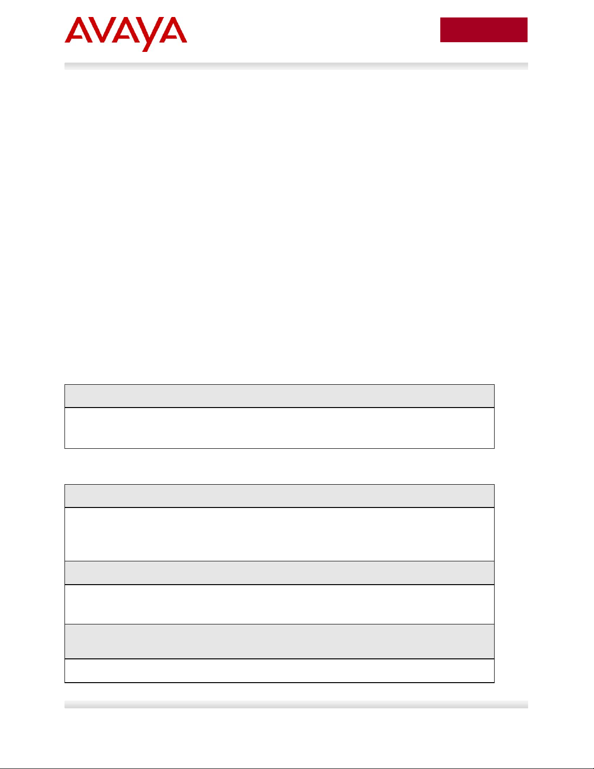
Symbols
Tip – Highlights a configuration or technical tip.
Note – Highlights important information to the reader.
Warning – Highlights important information about an action that may result in equipment
damage, configuration or data loss.
Text
Bold text indicates emphasis.
Italic text in a Courier New font indicates text the user must enter or select in a menu item, button or
command:
ERS5520-48T# show running-config
Output examples from Avaya devices are displayed in a Lucida Console font:
ERS5520-48T# show sys-info
Operation Mode: Switch
MAC Address: 00-12-83-93-B0-00
PoE Module FW: 6370.4
Reset Count: 83
Last Reset Type: Management Factory Reset
Power Status: Primary Power
Autotopology: Enabled
Pluggable Port 45: None
Pluggable Port 46: None
Pluggable Port 47: None
Pluggable Port 48: None
Base Unit Selection: Non-base unit using rear-panel switch
sysDescr: Ethernet Routing Switch 5520-48T-PWR
HW:02 FW:6.0.0.10 SW:v6.2.0.009
Mfg Date:12042004 HW Dev:H/W rev.02
Conventions
This section describes the text, image, and command conventions used in this document.
Avaya Inc. – External Distribution
Page 13

13
avaya.com
Aug 2012
1. Overview
This TCG covers standalone Avaya IP Phone sets and how they can be deployed on various Avaya
switches. It will cover features on Avaya switches related to VoIP with configuration examples. Overall,
topics that will be covered include the following:
Ethernet switch platforms that support PoE:
Ethernet Routing Switch 5000: 5520-48T-PWR, 5650TD-PWR, 5698TFD-PWR
Ethernet Routing Switch 4000: 4526T-PWR, 4550T-PWR, 4524GT-PWR, 4526GTX-PWR,
4548GT-PWR, 4526T-PWR+, 4550T-PWR+, 4826GTS-PWR+, 4850GTS-PWR+
Ethernet Routing Switch 3500: 3526T-PWR+, 3510GT-PWR+, 3526GT-PWR+
Ethernet Routing Switch 2500: 2526T-PWR, 2550T-PWR
Ethernet Routing Switch 8300
VoIP technologies:
Auto configuration via DHCP for VoIP Phone sets
Auto provisioning using tftp or http
Avaya Energy Saver (AES)
Authentication using EAPoL (802.1x)
Auto Detection Auto Configuration (ADAC)
Link Layer Discovery Protocol (LLDP)
Power over Ethernet (PoE)
Quality over Service (QoS)
Avaya Inc. – External Distribution
Page 14
14
avaya.com
Aug 2012
Section
Item
QoS
Description
2.3
DHCP or
optional LLDPMED
Manually configured1
Switch uses either DHCP or optional LLDP-MED
Network Policy to provision voice VLAN
2.4
ADAC – LLDP
Dectection
Automatically applied
to Voice VLAN2
Switch uses ADAC to automically detect IP Phone
using LLDP
2.5
ADAC – MAC
Detection
Automatically applied
to Voice VLAN
Switch uses ADAC to automatically detect IP
Phone using MAC address of IP Phone
2.6
DHCP
None
Uses DHCP to get VLAN ID for voice VLAN from
data DHCP scope using the ERS 8300
2.7
EAP MHMA
N/A
Optional configuration to enable IP Phones as an
EAP Supplicant using MD5
2.8
EAP NEAP
N/A
Optional configuration using the EAP NEAP
feature on the switch allowing it to authenticate
the IP Phone using its MAC address
2.9
EAP fail open
VLAN, guest
VLAN, and
RADIUS
assigned VLAN
N/A
Optional configuration using the EAP non-eapphone feature and other EAP options such as fail
open VLAN, guest VLAN, and RADIUS assigned
VLANs
2.10
DHCP and
Provisioning
files
N/A
DHCP server settings and provisioning files for
the IP Phones used in this example
2.11
Avaya Energy
Saver
N/A
Optional configuration adding AES to the switch
2.12
DHCP Server
N/A
Windows 2003 DHCP server settings
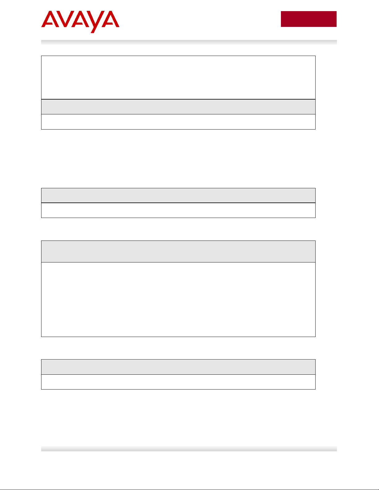
2. Automatic Provisioning Configuration
Examples
This section will cover various configuration examples to allow for automatic or zero-touch provisioning of
Avaya IP phones using Avaya data switches. The following chart summarizes each configuration
example.
1
QoS can be added in a number of methods such as simply trusting all traffic, applying filters, or enabling
Auto QoS (applies to Avaya 1100, 1200, or 2000 series only)
2
The LLDP-MED Network Policy can also set the QoS DSCP and p-bit priority values
Avaya Inc. – External Distribution
Page 15
15
avaya.com
Aug 2012
2.1 Reference Diagrams
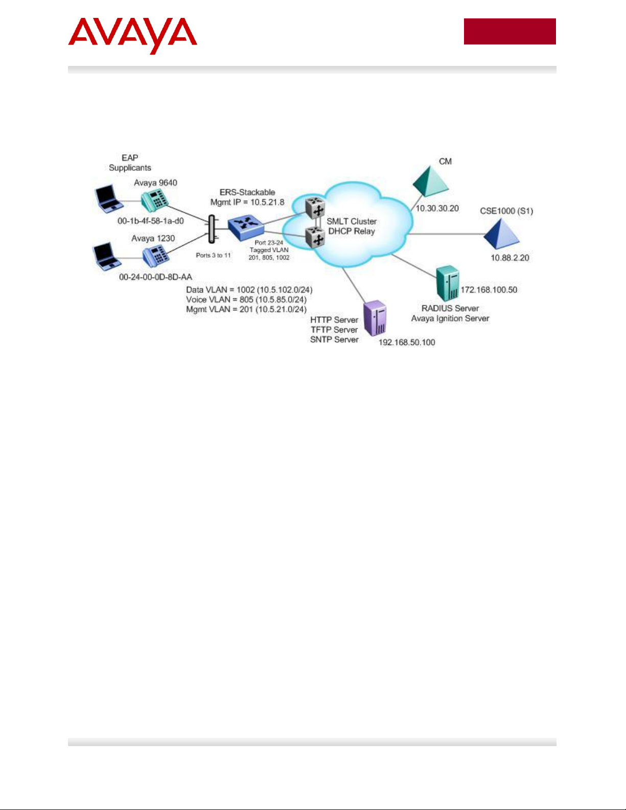
2.1.1 Diagram 1 : Stackable Ethernet Routing Switch
Figure 1: Base setup - Stackable Ethernet Routing Switch Setup
The following are the details for the base configuration:
ERS-Stackable is a stackable Ethernet Routing Switches (ERS 2500, 4000, or 5000 series) setup
as a Layer 2 switch connected to an SMLT Cluster
The SMLT Cluster requires that DHCP Relay be enabled with a DHCP Relay agent for both the
voice and data VLANs
Overall, we will configure the following
o Create Voice VLAN 805 with port members 3 to 11, 23, and 24
o Create Data VLAN 1002 with port members 3 to 11, 23, and 24
o Create Management VLAN 201 with port members 23 and 24
o Configure access ports 3 to 11 to allow untagged Data VLAN 1002 and tagged Voice
VLAN 805
o Configure core ports 23 and 24 using MLT 1 using VLAN tagging and with Spanning
disabled
o Use all the recommended SMLT best practices
Details regarding various Avaya IP Phone DHCP and provisioning file parameters are listed in
Appendix A
Avaya Inc. – External Distribution
Page 16
16
avaya.com
Aug 2012
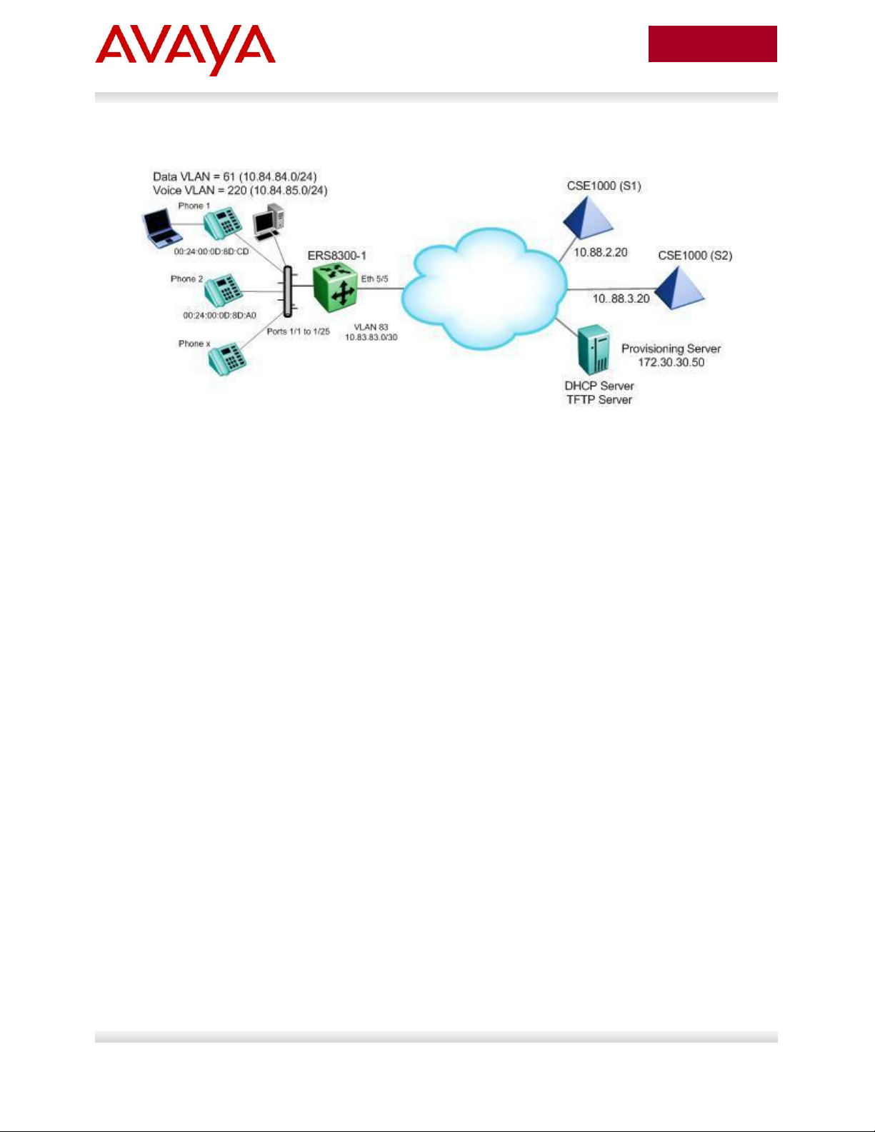
2.1.3 Diagram 2 : Ethernet Routing Switch 8300
Figure 2: Base setup - Ethernet Routing Switch 8300 Setup
Overall, we will configure the following:
Create Voice VLAN 220 with port members 1/1 to 1/25
Create Data VLAN 61 with port members 1/1 to 1/25
Create Trunk VLAN 83 with port member 5/5
Enable DHCP relay for VLAN 220 and 61
Enable Spanning Tree Fast-Start on ports 1/1 to 1/25 and disable STP on port 5/5
Configure all voice ports, 1/1 to 1/25, with POE priority of high
Enable RIP on all VLANs
By default, the ERS 8300 passes both the DSCP and p-bit values as-is. The p-bit value
determines the QoS level. For this example, we will not configure QoS as we are using VLAN
tagging for the Voice VLAN
Details regarding various Avaya IP Phone DHCP and provisioning file parameters are listed in
Appendix A
Avaya Inc. – External Distribution
Page 17
17
avaya.com
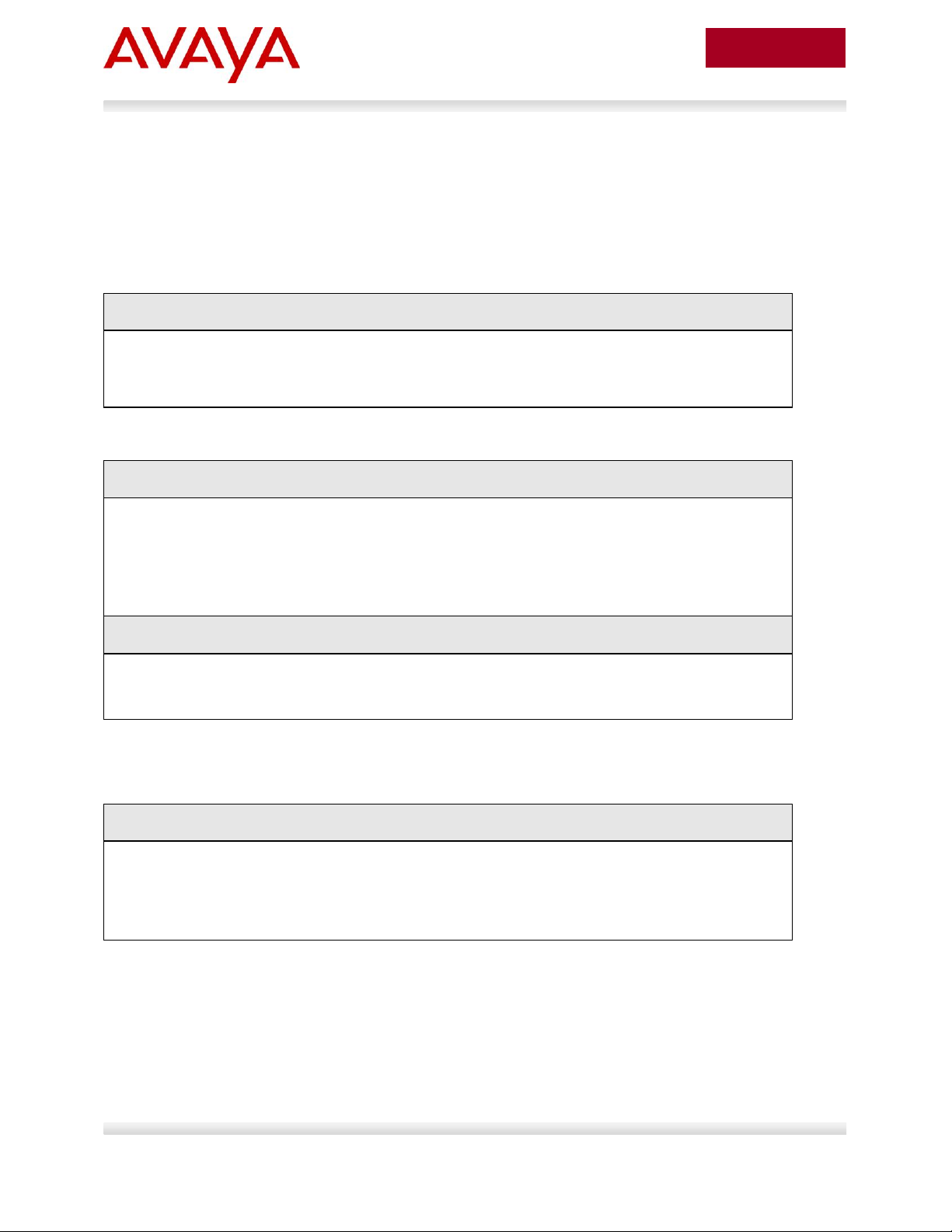
Aug 2012
Switch Model
Software Level
Notes
ERS 2500
4.4
Supports LLDP MED Policy via
ADAC
ERS 4000
5.6
Support LLDP MED Policy with
ADAC or without ADAC
ERS 5000
6.2.2.025
Support LLDP MED Policy with
ADAC or without ADAC
2.2 Switch Software levels
For this configuration example, the following software levels are used
Avaya Inc. – External Distribution
Page 18
18
avaya.com
Aug 2012
ERS-Stackable Step 1 - Enter configuration mode
ERS-Stackable>enable
ERS-Stackable#configure terminal
ERS-Stackable Step 1 – Create VLAN’s 201, 805, and 1002
ERS-Stackable(config)#vlan create 201 name mgmt type port
ERS-Stackable(config)#vlan create 805 name voice type port voice-vlan
ERS-Stackable(config)#vlan create 1002 name data type port
ERS-Stackable Step 2 – Enable VLAN tagging on all appropriate ports
ERS-Stackable(config)#vlan port 23-24 tagging tagall
ERS-Stackable(config)#vlan port 3-11 tagging untagpvidOnly
ERS-Stackable Step 3 – Set VLAN configuration control to automatic and add VLAN port
members
ERS-Stackable(config)# vlan configcontrol automatic
2.3 Auto Configuration with a Stackable Ethernet Routing Switch – with traffic filters for QoS and optional LLDP MED Policy
LLDP-MED Policy can be used with our without ADAC. If you choice to not use ADAC, by default, there
will be no QoS for the voice traffic. There are a number of ways to provide QoS for the voice traffic such
as:
Creating a new interface group with a class of trusted and applying this interface group to either
all ports or at minimum the uplink ports, call server ports, and all ports connected to IP phones.
This is simplest method, but, it also trusts all traffic which may or may not be acceptable
o Could create a filter to look for the data VLAN and remark to Standard service
Leave all ports with the default Interface Group with a class of untrusted and add a filter to look
for the voice VLAN and remark traffic to Premium service.
For this configuration example, we will simply create a traffic profile to match the voice VLAN and set the
CoS to Premium (p-bit value of 6 and DSCP value of 46).
This configuration example is in reference to diagram 1.
2.3.1 Stackable Switch Configuration
2.3.1.1 Go to configuration mode.
2.3.1.2 Create VLAN’s
Avaya Inc. – External Distribution
Page 19
19
avaya.com
Aug 2012
ERS-Stackable(config)#vlan members add 201 23-24
ERS-Stackable(config)#vlan members add 1002 3-11,23-24
ERS-Stackable(config)#vlan members add 805 3-11,23-24
ERS-Stackable(config)#vlan port 3-11 pvid 1002
ERS-Stackable Step 4 – Remove port members from the default VLAN
ERS-Stackable(config)#vlan members remove 1 3-11,23-24
Voice VLAN integration has been added to the various ERS stackable switches
beginning with release 5.6 for the ERS 4000, and 6.2 for the ERS 5000. This feature
offers a unified concept of Voice VLAN though various applications including ADAC,
EAP, and LLDP. Please see section 5.1 for more details.
ERS5698TFD-1 Step 1 – Add MLT with trunk members
ERS-Stackable(config)# mlt 1 enable member 23,24 learning disable
ERS-Stackable Step 1 – Enable VLACP on uplink port member 23 and 24 using the
recommended VLACP MAC and timeout values
ERS-Stackable(config)#vlacp macaddress 01:80:c2:00:00:0f
ERS-Stackable(config)#vlacp enable
ERS-Stackable(config)#interface fastEthernet 23,24
ERS-Stackable(config-if)#vlacp timeout short
ERS-Stackable(config-if)#vlacp timeout-scale 5
ERS-Stackable(config-if)#vlacp enable
ERS-Stackable(config-if)#exit
ERS-Stackable: Step 1 – Enable Discard Untagged Frames
ERS-Stackable(config)#vlan ports 23-24 filter-untagged-frame enable
2.3.1.3 Add MLT
2.3.1.4 Enable VLACP on trunk members using recommend values
2.3.1.5 Discard Untagged Frames on uplink ports to SMLT Cluster
Avaya Inc. – External Distribution
Page 20
20
avaya.com
Aug 2012
ERS-Stackable Step 1 – Set the IP address of the switch
ERS-Stackable(config)#vlan mgmt 201
ERS-Stackable(config)#ip address switch 10.5.21.8 netmask 255.255.255.0
default-gateway 10.5.21.1
ERS-Stackable Step 1 – Set the IP address of the switch
ERS-Stackable(config)#vlan mgmt 201
ERS-Stackable(config)#interface vlan 201
ERS-Stackable(config-if)#ip address 10.5.21.8 netmask 255.255.255.0
ERS-Stackable(config-if)#exit
ERS-Stackable Step 1 – Add the default route
ERS-Stackable(config)#ip routing
ERS-Stackable(config)#ip route 0.0.0.0 0.0.0.0 10.5.21.1 1
ERS-Stackable Step 1 – Set PoE Power level high on all VoIP ports
ERS-Stackable(config)#interface fastEthernet 3-11
ERS-Stackable(config)#poe poe-priority high
ERS-Stackable(config)#exit
2.3.1.6 Configure Management IP address on switch
An IP address can be added in one of two ways. If the switch is strictly used as a Layer 2 switch, then an
IP address can be added via the Layer 2 method using the ACLI command ip address <switch|stack> <IP
address> netmask <mask> default-gateway <default GW>.
2.3.1.6.1 Adding Management IP - Layer 2
2.3.1.6.2 Adding Management IP - Layer 3
2.3.1.7 Configure PoE levels - Optional
If you wish, you can change the default PoE level of low to either high or critical.
Avaya Inc. – External Distribution
Page 21
21
avaya.com
Aug 2012
If you are using an Avaya Ethernet Routing Switch 5000 or Ethernet Routing Switch
4000 (release 5.4 or higher), the default queue set (queue set 2) uses two strict queues
with large buffers. If you wish, you can provision another queue set if 2 queues do not
meet your needs. For example, queue set 4 which will provide three weighted queues
and one strict queue may be more acceptable to handle voice, video, and data. If you
do wish to use queue set 4, enter the ACLI command qos agent queue-set 4. You can
use the ACLI command show qos queue-set to view the make up for each queue set.
The ERS 2500 only supports one queue set, queue set 4, which supports one strict
queue and three weighted-round-robin (WWR) queues.
ERS-Stackable Step 1 – Change from default queue set (queue set 2) to queue set 4 and
reset the switch. Note, this only applies to the ERS 5000 or ERS 4000
ERS-Stackable(config)#qos agent queue-set 4
QoS queue setting isn't effective until after reset.
ERS-Stackable Step 2 – Create a new interface group with a class of trusted
ERS-Stackable(config)#qos if-group name trusted class trusted
ERS-Stackable(config)#qos if-assign port ALL name trusted
2.3.1.8 QoS
There are several options you can deploy to add QoS for the voice traffic.
Assign QoS class of trusted to all ports – easiest to implement and trust’s all traffic including soft
clients
Assign QoS class of trusted to all ports and adding a filter to remark the data traffic if you do not
trust traffic from the data VLAN – note, will will also remark soft clients to best effort
Set all access ports as untrusted (default setting), set uplink ports as trusted, and add a filter to
remark the voice traffic to CoS level of Premium – only provides QoS for the voice VLAN
Enable Auto QoS – only supported on limited Avaya products
o CS1000, CS2100, BCM, and/or SRG call servers
Enable ADAC – automatically provides QoS only to the voice VAN – please see next two sections
regarding ADAC provisioning
For this example, we will simply trust all traffic by setting all ports as trusted ports. This is the easiest
method for applying QoS for both untagged soft clients and tagged hard clients. We will also provision the
switch with queue set 4 providing 1 strict queue and 3 WRR queues which may be more acceptable to
handle voice, data, and video if the switch is either a ERS 4000 or ERS 5000; by default, the ERS 2500
uses queue set 4 while the ERS 4000 and ERS 5000 uses queue set 2. Otherwise, if the switch is only
supporting voice and data, you can use the default queue set 2 in reference to the ERS 4000 and ERS
5000.
Avaya Inc. – External Distribution
Page 22
22
avaya.com
Aug 2012
ERS-Stackable Step 1 – Traffic Profile Option. Configure either a traffic profile or ACL to
remark the data VLAN with a QoS level of Standard depending on switch model. Assuming
ERS-Stackable is an ERS 4000 or ERS 5000, it is recommend to use traffic profiles
ERS-Stackable(config)#qos traffic-profile classifier name one vlan-min 1002
vlan-max 1002 ethertype 0x800 update-dscp 0 update-1p 0
ERS-Stackable(config)#qos traffic-profile set port 1-13 name one
ERS-Stackable Step 1 – ACL Option. Configure either a traffic profile or ACL to remark the
data VLAN with a QoS level of Standard depending on switch model. ACL’s can be used
on a ERS 2500, ERS 4000, or ERS 5000 where it is recommended to use traffic profiles
over ACL’s if supported on the switch
ERS-Stackable(config)#qos l2-acl name one vlan-min 1002 vlan-max 1002 ethertype
0x800 update-dscp 0 update-1p 0
ERS-Stackable(config)#qos l2-acl name one ethertype 0x800 drop-action disable
ERS-Stackable(config)#qos acl-assign port 1-13 acl-type l2 name one
ERS-Stackable Step 1 – Enable STP Fast-Start and BPDU filtering on port 3 to 11
ERS-Stackable(config)#interface fastEthernet all
ERS-Stackable(config-if)#spanning-tree port 3-11 learning fast
ERS-Stackable(config-if)#spanning-tree port 3-11 bpdu-filtering timeout 0
ERS-Stackable(config-if)#spanning-tree port 3-11 bpdu-filtering enable
ERS-Stackable Step 1 – Add LLDP MED Network Policy
ERS-Stackable(config)#interface fastEthernet 3-11
ERS-Stackable(config-if)#lldp med-network-policies voice tagging tagged vlan-id
805
ERS-Stackable(config-if)#exit
If you wish, you can provision the switch to remark the data traffic to best effort if you do not trust the
traffic from the data VLAN.
2.3.1.9 Spanning Tree Configuration
2.3.1.10 Add LLDP-MED Network Policy – Optional for ERS 3500, ERS
4000 or ERS 5000
As an option, you can enable LLDP-MED with Network Policy to provision the voice VLAN without having
to use DHCP. In addition, you can also provision LLDP vendor specific settings to provision the call
server and file server (only for the Avaya 96xx IP phones as per this configuration example).
Note that the ERS 2500 requires ADAC must be used to enable LLDP MED. The ERS 3500 requires
software release 5.0.1 or higher to use LLDP-MED without ADAC.
Avaya Inc. – External Distribution
Page 23
23
avaya.com
Aug 2012
ERS-Stackable Step 1 – Enable LLDP TLVs
ERS-Stackable(config)#interface fastEthernet 3-11
ERS-Stackable(config-if)#lldp tx-tlv local-mgmt-addr port-desc sys-cap sys-desc
sys-name
ERS-Stackable(config-if)#lldp status txandRx config-notification
ERS-Stackable(config-if)#lldp tx-tlv med extendedPSE inventory location med-
capabilities network-policy
ERS-Stackable(config-if)#exit
ERS-Stackable Step 1 – Add LLDP Vendor Specific options
ERS-Stackable(config)#lldp vendor-specific avaya call-server 1 10.30.30.20
ERS-Stackable(config)#lldp vendor-specific avaya file-server 1 192.168.50.100
ERS-Stackable(config)#interface fastEthernet 3-11
ERS-Stackable(config)#lldp vendor-specific avaya dot1q-framing tagged
ERS-Stackable(config)#exit
ERS-Stackable Step 1 – Enable IP DHCP Snooping for voice VLAN 805 and data VLAN
1002
ERS-Stackable(config)#ip dhcp-snooping vlan 805
ERS-Stackable(config)#ip dhcp-snooping vlan 1002
ERS-Stackable(config)#ip dhcp-snooping enable
ERS-Stackable Step 2 – Enable IP Arp Inspection for voice VLAN 805 and data VLAN 1002
ERS-Stackable(config)#ip arp-inspection vlan 805
2.3.1.10.1 LLDP Tx-TLVs – Older Software Releases
Depending on the software release used, it may be nessessary to enable LLDP TLVs. This does not
apply to the ERS 4000 as of release 5.5, ERS 3500 as of release 5.0.1, and ERS 5000 as of release 6.3
from a factory default setting, but, to verify if the TLVs are enabled or not, please enter the ACLI
commands show lldp port 3-11 & show lldp tx-tlv.
2.3.1.10.2 Enable LLDP Vendor Specific settings
Up to 8 call-servers and up to 4 file-servers can be defined. Note that, for this configuration example, the
LLDP vendor specific settings only apply to the Avaya IP Phones.
2.3.1.11 Enable IP Anti-Spoofing and IP Source Guard – Optional
To prevent IP spoofing attacks, it is recommended to enabled IP DHCP Snooping and IP Arp Inspection.
In addition, it is recommended to enabled IP Source Guard which prevents a host from spoofing a source
IP other than that assigned by DHCP.
Avaya Inc. – External Distribution
Page 24
24
avaya.com
Aug 2012
ERS-Stackable(config)#ip arp-inspection vlan 1002
ERS-Stackable Step 3 – Enable core ports 23 and 24 as a trusted port
ERS-Stackable(config)#interface fastEthernet 23-24
ERS-Stackable(config-if)#ip dhcp-snooping trusted
ERS-Stackable(config-if)#ip arp-inspection trusted
ERS-Stackable(config-if)#exit
ERS-Stackable Step 4 – Enable IP Source Guard on access ports 3 to 11
ERS-Stackable(config)#interface fastEthernet 3-11
ERS-Stackable(config-if)#ip verify source
ERS-Stackable(config-if)#exit
Avaya Inc. – External Distribution
Page 25
25
avaya.com
Aug 2012
Step 1 – Verify VLAN Configuration as shown for ERS-Stackable where the default VLAN
should be VLAN 1002 on ports 3 to 11
ERS-Stackable#show vlan interface info 3-11
Result:
Filter Filter
Untagged Unregistered
Port Frames Frames PVID PRI Tagging Name
---- -------- ------------ ---- --- ------------- --------------
3 No Yes 1002 0 UntagPvidOnly Port 3
4 No Yes 1002 0 UntagPvidOnly Port 4
5 No Yes 1002 0 UntagPvidOnly Port 5
6 No Yes 1002 0 UntagPvidOnly Port 6
7 No Yes 1002 0 UntagPvidOnly Port 7
8 No Yes 1002 0 UntagPvidOnly Port 8
9 No Yes 1002 0 UntagPvidOnly Port 9
10 No Yes 1002 0 UntagPvidOnly Port 10
11 No Yes 1002 0 UntagPvidOnly Port 11
Step 2 – Verify VLAN Configuration as shown for ERS-Stackable where the ports 3 to 11
should be members of untagged VLAN 1002 and tagged VLAN 805
ERS-Stackable#show vlan interface vids 3-11
Result:
Port VLAN VLAN Name VLAN VLAN Name VLAN VLAN Name
---- ---- ---------------- ---- ---------------- ---- ----------------
3 805 voice 1002 data
---- ---- ---------------- ---- ---------------- ---- ----------------
4 805 voice 1002 data
---- ---- ---------------- ---- ---------------- ---- ----------------
5 805 voice 1002 data
---- ---- ---------------- ---- ---------------- ---- ----------------
6 805 voice 1002 data
---- ---- ---------------- ---- ---------------- ---- ----------------
7 805 voice 1002 data
2.3.2 Verify Operations
Via the ERS-Stackable switch, verify the following information:
Avaya Inc. – External Distribution
Page 26
26
avaya.com
Aug 2012
---- ---- ---------------- ---- ---------------- ---- ----------------
8 805 voice 1002 data
---- ---- ---------------- ---- ---------------- ---- ----------------
9 805 voice 1002 data
---- ---- ---------------- ---- ---------------- ---- ----------------
10 805 voice 1002 data
---- ---- ---------------- ---- ---------------- ---- ----------------
11 805 voice 1002 data
---- ---- ---------------- ---- ---------------- ---- ----------------
Step 3 – Verify IP Phone detection by issuing PoE port status command
ERS-Stackable#show poe-port-status 3-11
Result:
Admin Current Limit
Port Status Status Classification (Watts) Priority
---- ------- ----------------- -------------- ------- --------
3 Enable Detecting 0 16 Low
4 Enable Detecting 0 16 Low
5 Enable Detecting 0 16 Low
6 Enable Detecting 0 16 Low
7 Enable Delivering Power 2 16 Low
8 Enable Detecting 0 16 Low
9 Enable Delivering Power 2 16 Low
10 Enable Delivering Power 2 16 Low
11 Enable Detecting 0 16 Low
Step 4 – Verify IP Phone power usage by issuing PoE power measured command
ERS-Stackable#show poe-power-measurement 3-11
Result:
Port Volt(V) Current(mA) Power(Watt)
---- ------- ----------- ---------------
3 0.0 0 0.000
4 0.0 0 0.000
5 0.0 0 0.000
6 0.0 0 0.000
7 48.4 58 2.807
8 0.0 0 0.000
Avaya Inc. – External Distribution
Page 27
27
avaya.com
Aug 2012
9 48.4 61 2.952
10 48.4 58 2.807
11 0.0 0 0.000
Step 5 – Verify LLDP configuration.
ERS-Stackable#show running-config module 802.1ab
Result for ERS 4000 and ERS 5000 where the items highlighted in blue will not be shown
via the ERS 4000 as these are the default settings:
! Displaying only parameters different to default
!================================================
enable
configure terminal
!
! *** 802.1ab ***
!
!
! *** 802.1ab vendor-specific Avaya TLVs config ***
!
lldp vendor-specific avaya call-server 1 10.30.30.20
lldp vendor-specific avaya file-server 1 192.168.50.100
interface FastEthernet ALL
lldp port 1/3-11 vendor-specific avaya dot1q-framing tagged
exit
!
interface FastEthernet ALL
lldp port 3-11 config-notification
lldp tx-tlv port 3-11 local-mgmt-addr port-desc sys-desc sys-name
lldp tx-tlv port 3-11 med extendedPSE inventory location med-capabilities
network-policy
exit
!
! *** 802.1AB MED Voice Network Policies ***
!
interface FastEthernet ALL
lldp med-network-policies port 3-11 voice dscp 46 priority 6 tagging tagged vla
n-id 805
exit
Avaya Inc. – External Distribution
Page 28
28
avaya.com
Aug 2012
Result for ERS 2500:
!
! *** 802.1ab ***
!
! *** 802.1ab vendor-specific Avaya TLVs config ***
!
lldp vendor-specific avaya call-server 1 10.30.30.20
lldp vendor-specific avaya file-server 1 192.168.50.100
interface FastEthernet ALL
lldp port 1/3-11,1/13 vendor-specific avaya dot1q-framing tagged
exit
Step 2 – Verify LLDP network policy configuration – note, this only applies to the ERS 4000
or ERS 5000 as this command is not available on the ERS 2500
ERS-Stackable#show lldp med-network-policies port 3-11
or, via some switches
ERS-Stackable#show lldp med-network-policies port 3-11 voice
Result:
-------------------------------------------------------------------------------
LLDP-MED network-policies
-------------------------------------------------------------------------------
-------------------------------------------------------------------------------
Unit/ Application Type VlanID Tagging DSCP Priority
Port
-------------------------------------------------------------------------------
3 Voice 805 tagged 46 6
4 Voice 805 tagged 46 6
5 Voice 805 tagged 46 6
6 Voice 805 tagged 46 6
7 Voice 805 tagged 46 6
8 Voice 805 tagged 46 6
9 Voice 805 tagged 46 6
10 Voice 805 tagged 46 6
11 Voice 805 tagged 46 6
-------------------------------------------------------------------------------
Avaya Inc. – External Distribution
Page 29

29
avaya.com
Aug 2012
Step 3 – Verify LLDP MED configuration; for example, the following ACLI command shows
LLDP MED configuration for port 11
ERS-Stackable#show lldp port 13 local-sys-data med
Result:
-------------------------------------------------------------------------------
lldp local-sys-data chassis
-------------------------------------------------------------------------------
-------------------------------------------------------------------------------
ChassisId: MAC address 00:13:0a:35:e8:00
SysName: ERS-Stackable
SysCap: rB / rB (Supported/Enabled)
SysDescr:
Ethernet Routing Switch ERS-Stackable HW:05 FW:6.0.0.10 SW:v6.2.0.009
MED-Device class: Network Connectivity Device
MED-POE Device Type: PSE Device
HWRev: 05 SerialNumber: SDNI2S00L9
FWRev: 6.0.0.10 SWRev: v6.2.0.009
ManufName: Avaya ModelName: ERS-Stackable
-------------------------------------------------------------------------------
lldp local-sys-data port
-------------------------------------------------------------------------------
Port: 11
MED-Capabilities: CNLSI
MED-PSE PDPort Priority: Low Power Value: 16.0 Watt
MED-Application Type: Voice VLAN ID: 805
L2 Priority: 6 DSCP Value: 46 Tagged Vlan, Policy defined
-------------------------------------------------------------------------------
Sys capability: O-Other; R-Repeater; B-Bridge; W-WLAN accesspoint; r-Router;
T-Telephone; D-DOCSIS cable device; S-Station only.
Med Capabilities-C: N-Network Policy; L-Location Identification; I-Inventory;
S-Extended Power via MDI - PSE; D-Extended Power via MDI - PD.
Avaya Inc. – External Distribution
Page 30

30
avaya.com
Aug 2012
Step 4 – Verify LLDP neighbor details assuming an Avaya 9640G is connected to port 11
ERS-Stackable# show lldp port 11 neighbor detail
Result:
-------------------------------------------------------------------------------
lldp neighbor
-------------------------------------------------------------------------------
Port: 11 Index: 89 Time: 11 days, 04:49:49
ChassisId: Network address IPv4 10.1.90.222
PortId: MAC address 00:1b:4f:58:1a:d0
SysName: AVB581AD0
SysCap: TB / TB (Supported/Enabled)
PVID: PPVID Supported: none
VLAN Name List: none PPVID Enabled: none
Dot3-MAC/PHY Auto-neg: supported/enabled OperMAUtype: 100BaseTXFD
PMD auto-neg: 10Base(T, TFD), 100Base(TX, TXFD), 1000Base(TFD)
MED-Capabilities: CNDI / CNDI (Supported/Current)
MED-Device type: Endpoint Class 3
MED-Application Type: Voice VLAN ID: 805
L2 Priority: 6 DSCP Value: 46 Tagged Vlan, Policy defined
Med-Power Type: PD Device Power Source: FromPSE
Power Priority: Low Power Value: 5.6 Watt
HWRev: 9640GD01A FWRev: hb96xxua3_11.bin
SWRev: ha96xxua3_11.bin SerialNumber: 10N520301110
ManufName: Avaya ModelName: 9640G
AssetID:
-------------------------------------------------------------------------------
Sys capability: O-Other; R-Repeater; B-Bridge; W-WLAN accesspoint; r-Router;
T-Telephone; D-DOCSIS cable device; S-Station only.
Total neighbors: 3
Med Capabilities-C: N-Network Policy; L-Location Identification; I-Inventory;
S-Extended Power via MDI - PSE; D-Extended Power via MDI - PD.
Avaya Inc. – External Distribution
Page 31

31
avaya.com
Aug 2012
Step 5 – Verify LLDP neighbor vendor-specific Avaya IP Phones
ERS-Stackable# show lldp neighbor vendor-specific avaya phone-ip
Result:
------------------------------------------------------------------------------
Neighbors LLDP info - Avaya TLVs
------------------------------------------------------------------------------
------------------------------------------------------------------------------
Port: 7
Avaya Phone IP:
Address: 10.1.90.221
Netmask: 255.255.255.0
Gateway: 10.1.90.1
Port: 11
Avaya Phone IP:
Address: 10.1.90.222
Netmask: 255.255.255.0
Gateway: 10.1.90.1
Avaya Inc. – External Distribution
Page 32

32
avaya.com
Aug 2012
ERS-Stackable Step 1
ERS-Stackable(config)#interterface fastEthernet all
ERS-Stackable(config-if)#no lldp med-network-policies
ERS-Stackable(config-if)#exit
ERS-Stackable Step 2 – Enable ADAC using VLAN 805, set the operation mode to taggedframes, and add the uplink port 23
ERS-Stackable(config)#adac voice-vlan 805
ERS-Stackable(config)#adac op-mode tagged-frames
ERS-Stackable(config)#adac uplink-port 23
ERS-Stackable(config)#adac traps enable
ERS-Stackable(config)#adac enable
Please note the following:
VLAN 805 must not exist prior to configuring ADAC – this only applies to the ERS 2500.
Note, this does not apply if VLAN is provisioned as a Voice VLAN on either the
ERS 3500, ERS 4000 or ERS 5000 using either ACLI command vlan voice-vlan
805 or vlan create 805 type port voice-vlan
The command adac uplink-port 23 will automatically enable VLAN tagging on port 23
and 24 and add these ports as a member of VLAN 805 and MLT 1.
Please not that in reference to newer software releases for Avaya stackable switches, a
default LLDP MED policy has been added. The default values for this policy is
application type = voice, tagging = untagged, DSCP = 46, VLAN priority = 6, and VLAN
id= 0. If ADAC is configured and an IP Phone is detected, the dynamic LLDP MED
policy with the ADAC Voice VLAN ID will never be installed, resulting in the IP phone
not receiving the VLAN configuration for the case when ADAC tagged frames is used.
2.4 Auto Configuration with a Stackable Ethernet Routing Switch – with ADAC for QoS using LLDP Dectection
The following configuration example covers setting up a network to support both voice and data to
support Auto-Configuration with Avaya’s stackable Ethernet Routing switches and IP Phone sets. ADAC
LLDP-MED detection will be enabled detect the IP Phone and apply QoS.
This configuration example is in reference to diagram 1 and base configuration in section 2.3.
2.4.1 Stackable Ethernet Switch Configuration
Please note, the ADAC configuration is exactly the same as that used in section 2.3 with the only
difference that ADAC is used to automatically detect the IP Phone via LLDP and provide QoS.
2.4.1.1 Enable ADAC Globally
Avaya Inc. – External Distribution
Page 33

33
avaya.com
Aug 2012
The same behavior applies to ADAC uplink/call server ports. This happens because the
default MED policy is static and overrides the dynamic one that should be installed by
ADAC.
If ADAC is to be used, then it is recommended that the default 802.1AB/LLDP MED
policies are deleted on telephony ports and on uplink/call server ports. Use the interface
command no lldp med-network-policies on telephony ports and on uplink/call server
ports, prior to configuring ADAC. Or if you already have ADAC enable, as long as the IP
Phone is detected by ADAC, you can use the interface command lldp med-network-
policies voice tagging tagged vlan-id <VLAN Id>.
ERS-Stackable Step 1 – Enable ADAC on port members 3 to 11, set the ADAC detection to
LLDP only, and enable the ADAC tag mode to tagged frames and untag the default VLAN
ERS-Stackable(config)#interface fastEthernet 3-11
**ERS-Stackable(config-if)#adac detection lldp
ERS-Stackable(config-if)#no adac detection mac
ERS-Stackable(config-if)#adac tagged-frames-tagging untag-pvid-only
ERS-Stackable(config-if)#adac enable
ERS-Stackable(config-if)#exit
**Note that by default, ADAC detection for MAC and LLDP is enabled. Hence, the
command adac detection lldp is not required and only used in this example to show that
there is a command to enable or disable the detection type.
ERS-Stackable Step 1 – Enable LLDP-MED on port 3 to 11
ERS-Stackable(config)#interface fastEthernet 3-11
ERS-Stackable(config-if)#lldp tx-tlv local-mgmt-addr port-desc sys-cap sys-desc
sys-name
ERS-Stackable(config-if)#lldp status txAndRx config-notification
ERS-Stackable(config-if)#lldp tx-tlv med extendedPSE med-capabilities network-
policy
ERS-Stackable(config-if)#exit
2.4.1.2 Enable ADAC at interface level
2.4.1.3 Enable LLDP TLVs
In software releases 6.2 or earlier for the ERS 5000, one must enable LLDP TX-TLVs. This does not
apply to the ERS 4000 as of release 5.5, the ERS 3500 as of release 5.0.1, and the ERS 5000 as of
release 6.3, but, to verify if the TLVs are enabled or not, please enter the ACLI commands show lldp port
3-11 & show lldp tx-tlv.
Avaya Inc. – External Distribution
Page 34

34
avaya.com
Aug 2012
ERS-Stackable Step 1 – Add LLDP Vendor Specific options
ERS-Stackable(config)#lldp vendor-specific avaya call-server 1 10.30.30.20
ERS-Stackable(config)#lldp vendor-specific avaya file-server 1 192.168.50.100
ERS-Stackable(config)#interface fastEthernet 3-11
ERS-Stackable(config)#lldp vendor-specific avaya dot1q-framing tagged
ERS-Stackable(config)#exit
2.4.1.4 Enable LLDP Vendor Specific settings
Up to 8 call-servers and up to 4 file-servers can be defined. Note that, for this configuration example, the
LLDP vendor specific settings only apply to the Avaya 96xx IP Phones.
Avaya Inc. – External Distribution
Page 35

35
avaya.com
Aug 2012
Step 1 – Verify LLDP neighbor details by using the following command:
ERS-Stackable#show lldp port 11 neighbor detail
Result:
-------------------------------------------------------------------------------
lldp neighbor
-------------------------------------------------------------------------------
Port: 11 Index: 4 Time: 0 days, 00:53:14
ChassisId: Network address IPv4 10.1.90.222
PortId: MAC address 00:1b:4f:58:1a:d0
SysName: AVB581AD0
SysCap: TB / TB (Supported/Enabled)
PVID: PPVID Supported: none
VLAN Name List: none PPVID Enabled: none
Dot3-MAC/PHY Auto-neg: supported/enabled OperMAUtype: 100BaseTXFD
PMD auto-neg: 10Base(T, TFD), 100Base(TX, TXFD), 1000Base(TFD)
MED-Capabilities: CNDI / CNDI (Supported/Current)
MED-Device type: Endpoint Class 3
MED-Application Type: Voice VLAN ID: 805
L2 Priority: 6 DSCP Value: 46 Tagged Vlan, Policy defined
Med-Power Type: PD Device Power Source: FromPSE
Power Priority: Low Power Value: 5.6 Watt
HWRev: 9640GD01A FWRev: hb96xxua3_11.bin
SWRev: ha96xxua3_11.bin SerialNumber: 10N520301110
ManufName: Avaya ModelName: 9640G
AssetID:
-------------------------------------------------------------------------------
Sys capability: O-Other; R-Repeater; B-Bridge; W-WLAN accesspoint; r-Router;
T-Telephone; D-DOCSIS cable device; S-Station only.
2.4.2 Verify operations
2.4.2.1 Verify LLDP-MED Operations
The following command is used to retrieve LLDP neighbor information from the IP Phone set assuming
we have an Avaya 9640G connected to port 11 on ERS-Stackable.
Avaya Inc. – External Distribution
Page 36

36
avaya.com
Aug 2012
Total neighbors: 3
Med Capabilities-C: N-Network Policy; L-Location Identification; I-Inventory;
S-Extended Power via MDI - PSE; D-Extended Power via MDI - PD.
Step 2 – Verify LLDP-MED ERS-Stackable LLDP-MED network policy:
ERS-Stackable# show lldp med-network-policies port 7
Result:
-------------------------------------------------------------------------------
LLDP-MED network-policies
-------------------------------------------------------------------------------
-------------------------------------------------------------------------------
Unit/ Application Type VlanID Tagging DSCP Priority
Port
-------------------------------------------------------------------------------
7 Voice 805 tagged 46 6
-------------------------------------------------------------------------------
Step 3 – Verify LLDP neighbor vendor-specific Avaya IP Phones
ERS-Stackable# show lldp neighbor vendor-specific avaya phone-ip
Result:
------------------------------------------------------------------------------
Neighbors LLDP info - Avaya TLVs
------------------------------------------------------------------------------
------------------------------------------------------------------------------
Port: 7
Avaya Phone IP:
Address: 10.1.90.221
Netmask: 255.255.255.0
Gateway: 10.1.90.1
Port: 11
Avaya Phone IP:
Address: 10.1.90.222
Netmask: 255.255.255.0
Gateway: 10.1.90.1
Avaya Inc. – External Distribution
Page 37

37
avaya.com
Aug 2012
Option
Verify
ChassissId:
Displays the IP address of the PD device
PortId:
Displays the MAC address of the PD device
L2 Priority:
Displays as 6 indicating the 802.1p value for a CoS class of Premium.
DSCP Value:
Displays as decimal 46 indicating the DSCP value for a CoS class of
Premium.
VLAN ID:
Displays as 805, the Voice VLAN ID.
Power Value:
Displays the PoE power consumed by the PD device.
ManufName:
Displays Avaya
ModelName:
Displays as the Avaya IP phone model, for this example, 9640G should
be displayed.
Via the ERS-Stackable switch, verify the following information:
Avaya Inc. – External Distribution
Page 38

38
avaya.com
Aug 2012
Step 1 – Verify LLDP neighbor details by using the following command:
ERS-Stackable#show adac interface 3-11
Result:
Auto Oper Auto
Port Type Detection State Configuration T-F PVID T-F Tagging
---- ---- --------- -------- ------------- --------- ---------------
3 T Enabled Enabled Not Applied No Change Untag PVID Only
4 T Enabled Enabled Not Applied No Change Untag PVID Only
5 T Enabled Enabled Not Applied No Change Untag PVID Only
6 T Enabled Enabled Not Applied No Change Untag PVID Only
7 T Enabled Enabled Applied No Change Untag PVID Only
8 T Enabled Enabled Not Applied No Change Untag PVID Only
9 T Enabled Enabled Applied No Change Untag PVID Only
10 T Enabled Enabled Not Applied No Change Untag PVID Only
11 T Enabled Enabled Not Applied No Change Untag PVID Only
Option
Verify
Type
Verify that the ADAC type is set for T indicating the port is configured
for ADAC type of tagged port
Auto Detection
Verify the ADAC detection is set to Enabled for ports 3 to 11
Oper State:
Verify the ADAC operation state is set to Enabled for port 3 to 11
Auto Configuration
In our example, ports 7 and 9 should indicate Applied while the other
ports should indicate Not Applied as only ports 7 and 9 have IP Phone
sets detected by ADAC
T-F PVID
Verify the tagged frames No Change which indicates do not change the
default PVID
T-F Tagging
Verify the port members 3 to 11 are set to Untag PVID only
2.4.2.2 Verify ADAC Operations
The following command is used to view ADAC detection. Assuming we have IP Phones connected to
ports 7 and 9 the results should be as follows
Via the ERS-Stackable switch, verify the following information:
Avaya Inc. – External Distribution
Page 39

39
avaya.com
Aug 2012
Step 1 – Verify LLDP neighbor details by using the following command:
ERS-Stackable#show adac detection interface 3-11
Result:
MAC LLDP
Port Detection Detection
---- --------- ---------
3 Disabled Enabled
4 Disabled Enabled
5 Disabled Enabled
6 Disabled Enabled
7 Disabled Enabled
8 Disabled Enabled
9 Disabled Enabled
10 Disabled Enabled
11 Disabled Enabled
Option
Verify
MAC Detection
For this example, we disabled ADAC MAC detection, hence the value
should be Disabled
LLDP Detection
For this example, we enabled ADAC LLDP detection, hence the value
should be Enabled
2.4.2.3 Verify ADAC Detection
The following command is used to view ADAC detection configuration.
Via the ERS-Stackable switch, verify the following information:
Avaya Inc. – External Distribution
Page 40

40
avaya.com
Aug 2012
ERS-Stackable Step 1 – Add ADAC voice VLAN with operation mode of tagged frame,
enable ADAC traps, and add ADAC uplink port 23
ERS-Stackable(config)#adac voice-vlan 805
ERS-Stackable(config)#adac op-mode tagged-frames
ERS-Stackable(config)#adac uplink-port 23
ERS-Stackable(config)#adac traps enable
ERS-Stackable(config)#adac enable
Please note the following:
VLAN 805 must not exist prior to configuring ADAC.
Note, this does not apply if VLAN is provisioned as a Voice VLAN
The command adac uplink-port 23 will automatically enable VLAN tagging on port 23
and 24 and add these ports as a member of VLAN 805 and MLT 1.
ERS-Stackable Step 1 – Enable ADAC on port members 3 to 11 and enable ADAC tagged
frames with the option to untag the default PVID. By default, ADAC MAC detection is
already enabled, hence it is not necessary to enable ADAC MAC detection.
ERS-Stackable(config)#interface fastEthernet all
ERS-Stackable(config-if)#adac port 3-11 tagged-frames-tagging untag-pvid-only
ERS-Stackable(config-if)#adac port 3-11 enable
ERS-Stackable(config-if)#exit
2.5 Auto Configuration with a Stackable Ethernet Routing Switch – with ADAC for QoS using MAC Address Dectection
The following configuration example covers setting up a network to support both voice and data to
support Auto-Configuration with Avaya’s stackable Ethernet Routing switches and IP Phone sets. ADAC
MAC detection will be enabled detect the IP Phone and apply QoS.
This configuration example is in reference to diagram 1 and base configuration in section 2.3.
2.5.1 Stackable Ethernet Switch Configuration
Please note, the ADAC configuration is exactly the same as that used in section 2.3 with only exception
that the Voice VLAN is created by ADAC.
2.5.1.1 Configure ADAC
2.5.1.2 Enable ADAC at interface level
Avaya Inc. – External Distribution
Page 41

41
avaya.com
Aug 2012
ERS-Stackable Step 1 – Add to ADAC the IP Phone set MAC address range for the Avaya
1230 and 9640 IP phone sets used in this example
ERS-Stackable(config)#adac mac-range-table low-end 0024.000D.0000 high-end
0024.000D.ffff
ERS-Stackable(config)#adac mac-range-table low-end 001b.4f58.0000 high-end
001b.4f58.ffff
ERS-Stackable: Step 1 – Disable Filter unregistered Frames on MLT trunks members
ERS-Stackable(config)#vlan ports 3-11 filter-unregistered-frames disable
2.5.1.3 Add ADAC MAC address range
2.5.1.4 Disable unregistered frames on ADAC port members
Avaya Inc. – External Distribution
Page 42

42
avaya.com
Aug 2012
Step 1 – Verify the VLAN configuration for all access and trunk port members prior to
connecting an IP phone to any port member
ERS-Stackable#show vlan interface info 3-11,23-24
Result:
Filter Filter
Untagged Unregistered
Port Frames Frames PVID PRI Tagging Name
---- -------- ------------ ---- --- ------------- ----------------
3 No No 1002 0 UntagAll Port 3
4 No No 1002 0 UntagAll Port 4
5 No No 1002 0 UntagAll Port 5
6 No No 1002 0 UntagAll Port 6
7 No No 1002 0 UntagAll Port 7
8 No No 1002 0 UntagAll Port 8
9 No No 1002 0 UntagAll Port 9
10 No No 1002 0 UntagAll Port 10
11 No No 1002 0 UntagAll Port 11
23 Yes Yes 1 0 TagAll Port 23
24 Yes Yes 1 0 TagAll Port 24
Step 2 – Verify the VLAN configuration for all access port members after connecting an IP
phone to a port member. For example, assuming we have attached an Avaya IP phone
connected to ports 3 and port 4
ERS-Stackable# show vlan interface info 3-4
Result:
Filter Filter
Untagged Unregistered
Port Frames Frames PVID PRI Tagging Name
---- -------- ------------ ---- --- ------------- ----------------
3 No No 1002 0 UntagPvidOnly Port 10
4 No No 1002 0 UntagPvidOnly Port 11
2.5.2 Verify configuration
2.5.2.1 VLAN Information
Avaya Inc. – External Distribution
Page 43

43
avaya.com
Aug 2012
Step 3 – Verify the VLAN PVIDs for all access port members after connecting an IP phone
to a port member. For example, assuming we have attached an Avaya IP phone to ports 3
and port 4
ERS-Stackable# show vlan interface vids 3-6
Result:
Port VLAN VLAN Name VLAN VLAN Name VLAN VLAN Name
---- ---- ---------------- ---- ---------------- ---- ----------------
3 1002 data 805 Voice_VLAN
---- ---- ---------------- ---- ---------------- ---- ----------------
4 1002 data 805 Voice_VLAN
---- ---- ---------------- ---- ---------------- ---- ----------------
5 1002 data
---- ---- ---------------- ---- ---------------- ---- ----------------
6 1002 data
---- ---- ---------------- ---- ---------------- ---- ----------------
Option
Verify
PVID
Verify that the default PVID on port member 3 to 11 is 1002
Tagging
Verify that ports 3 to 11 are configured as UntagAll when no IP Phones
have been detected by ADAC and set to UntagPvidOnly only when an
IP Phone has successfully been detected by ADAC
Filter Untagged
Frames
Verify that ports 3 to 11 are configured as No and port members 23 and
24 are configured as Yes
Filter Unregistered
Frames
Verify that ports 3 to 11 are configured as No and port members 23 and
24 are configured as Yes
VLAN and VLAN
Name
Verify that ports 3 to 11 are members of VLANs 1002 and only
members of VLAN 805 when an IP Phone has been detected by ADAC.
Via the ERS-Stackable switch, verify the following information:
Avaya Inc. – External Distribution
Page 44

44
avaya.com
Aug 2012
Step 1 – Verify ADAC Global Settings
ERS-Stackable#show adac
Result:
ADAC Global Configuration
---------------------------------------
ADAC Admin State: Enabled
ADAC Oper State: Enabled
Operating Mode: Tagged Frames
Traps Control Status: Enabled
Voice-VLAN ID: 805
Call Server Port: None
Uplink Port: 23
Option
Verify
ADAC Admin State:
ADAC Oper State:
Verify that the ADAC administrative and operation state is Enabled
Operating Mode
Verify the ADAC operating mode is set for Tagged Frames
Traps Control Status:
Verify the ADAC traps is set for Enabled
Voice-VLAN ID:
Verify the ADAC voice VLAN is set for 805
Uplink Port:
Verify the ADAC uplink port is configured for port 23
2.5.2.2 Verify ADAC Global Information
Via the ERS-Stackable switch, verify the following information:
Avaya Inc. – External Distribution
Page 45

45
avaya.com
Aug 2012
Step 2 – Verify ADAC at interface level
ERS-Stackable#show adac interface 3-11
Result:
Auto Oper Auto
Port Type Detection State Configuration T-F PVID T-F Tagging
---- ---- --------- -------- ------------- --------- ---------------
3 T Enabled Enabled Applied No Change Untag PVID Only
4 T Enabled Enabled Applied No Change Untag PVID Only
5 T Enabled Enabled Not Applied No Change Untag PVID Only
6 T Enabled Enabled Not Applied No Change Untag PVID Only
7 T Enabled Enabled Not Applied No Change Untag PVID Only
8 T Enabled Enabled Not Applied No Change Untag PVID Only
9 T Enabled Enabled Not Applied No Change Untag PVID Only
10 T Enabled Enabled Not Applied No Change Untag PVID Only
11 T Enabled Enabled Not Applied No Change Untag PVID Only
The filter unregistered frames must be disabled for ADAC to work. If you connect an IP
phone set to a port and the auto configuration state is Not Applied, either the MAC
address is not part of the ADAC MAC table or filter unregistered frames is enabled.
Option
Verify
Type
Verify that the ADAC type is set for T indicating the port is configured
for ADAC type of tagged port
Auto Detection
Verify the ADAC detection is set to Enabled for port 3 to 11
Oper State:
Verify the ADAC operation state is set to Enabled for port 3 to 11
Auto Configuration
In our example, ports 3 and 4 should indicate Applied while ports 5 to
11 should indicate Not Applied as only ports 3 and 4 have IP Phone
sets detected by ADAC
T-F PVID
Verify the tagged frames No Change which indicates do not change the
default PVID
T-F Tagging
Verify the port members 3 to 11 are set to Untag PVID only
2.5.2.3 Verify ADAC at interface level
Assuming ADAC has detected an Avaya IP phone on ports 3 and 4.
Via the ERS-Stackable switch, verify the following information:
Avaya Inc. – External Distribution
Page 46

46
avaya.com
Aug 2012
Step 3 – Verify ADAC MAC address range
ERS-Stackable# show adac mac-range-table
Result:
Lowest MAC Address Highest MAC Address
------------------------ -------------------------
00-0A-E4-01-10-20 00-0A-E4-01-23-A7
00-0A-E4-01-70-EC 00-0A-E4-01-84-73
00-0A-E4-01-A1-C8 00-0A-E4-01-AD-7F
00-0A-E4-01-DA-4E 00-0A-E4-01-ED-D5
00-0A-E4-02-1E-D4 00-0A-E4-02-32-5B
00-0A-E4-02-5D-22 00-0A-E4-02-70-A9
00-0A-E4-02-D8-AE 00-0A-E4-02-FF-BD
00-0A-E4-03-87-E4 00-0A-E4-03-89-0F
00-0A-E4-03-90-E0 00-0A-E4-03-B7-EF
00-0A-E4-04-1A-56 00-0A-E4-04-41-65
00-0A-E4-04-80-E8 00-0A-E4-04-A7-F7
00-0A-E4-04-D2-FC 00-0A-E4-05-48-2B
00-0A-E4-05-B7-DF 00-0A-E4-06-05-FE
00-0A-E4-06-55-EC 00-0A-E4-07-19-3B
00-0A-E4-08-0A-02 00-0A-E4-08-7F-31
00-0A-E4-08-B2-89 00-0A-E4-09-75-D8
00-0A-E4-09-BB-9D 00-0A-E4-09-CF-24
00-0A-E4-09-FC-2B 00-0A-E4-0A-71-5A
00-0A-E4-0A-9D-DA 00-0A-E4-0B-61-29
00-0A-E4-0B-BB-FC 00-0A-E4-0B-BC-0F
00-0A-E4-0B-D9-BE 00-0A-E4-0C-9D-0D
00-13-65-FE-F3-2C 00-13-65-FF-ED-2B
00-15-9B-FE-A4-66 00-15-9B-FF-24-B5
00-16-CA-00-00-00 00-16-CA-01-FF-FF
00-16-CA-F2-74-20 00-16-CA-F4-BE-0F
00-17-65-F6-94-C0 00-17-65-F7-38-CF
00-17-65-FD-00-00 00-17-65-FF-FF-FF
00-18-B0-33-90-00 00-18-B0-35-DF-FF
00-19-69-83-25-40 00-19-69-85-5F-FF
2.5.2.4 Verify ADAC MAC Address table
Avaya Inc. – External Distribution
Page 47

47
avaya.com
Aug 2012
00-1B-4F-58-00-00 00-1B-4F-58-FF-FF
00-24-00-0D-00-00 00-24-00-0D-FF-FF
Total Ranges: 30
Option
Verify
Lowest MAC Address
Highest MAC Address
Verify the ADAC MAC address range you added for the Avaya 1230
and 9640 phone sets have been added from 00-24-00-0D-00-00 to 00-
24-00-0D-FF-FF and 00-1B-4F-58-00-00 to 00-1B-4F-58-FF-FF.
On ERS-Stackable, verify the following information:
Avaya Inc. – External Distribution
Page 48

48
avaya.com
Aug 2012
ERS8300-1 Step 1 - Enter configuration mode – ACLI only
ACLI
ERS8300-1:5>enable
Password: ******
ERS8300-1:5#configure terminal
ERS8300-1 Step 1 – Enable VLAN tagging on ports 1/1 to 1/25
CLI
ERS8300-1:5# config ether 1/1-1/25 perform-tagging enable
ACLI
ERS8300-1:5(config)#interface fastEthernet 1/1-1/25
ERS8300-1:5(config-if)#encapsulation dot1q
ERS8300-1:5(config-if)#exit
2.6 Auto Configuration with an Ethernet Routing Switch 8300 using DHCP
The following configuration example covers setting up a network to support both voice and data to
support automatic provisioning on Avaya’s IP Phone sets. We will cover how to setup the edge switch, in
this example an Ethernet Routing Switch 8300, for L3 operations using RIP.
By default, the ERS 8300 passes both the DSCP and p-bit values as-is. The p-bit value determines the
QoS level. For this example, we will not configure QoS as we are using VLAN tagging for the Voice
VLAN.
This configuration example is in reference to diagram 1.
2.6.1 ERS 8300 Configuration
2.6.1.1 Go to configuration mode.
2.6.1.2 Enable VLAN tagging on access port members
Avaya Inc. – External Distribution
Page 49

49
avaya.com
Aug 2012
ERS8300-1 Step 1 – Remove port members from the default VLAN 1 and create VLAN 61,
add port members, enable RIP, and enable DHCP relay
CLI
ERS8300-1:5# config vlan 1 port remove 1/1-1/25
ERS8300-1:5# config vlan 61 create byport 1
ERS8300-1:5# config vlan 61 name Data
ERS8300-1:5# config vlan 61 ports add 1/1-1/25
ERS8300-1:5# config vlan 61 ip create 10.84.84.1/24
ERS8300-1:5# config vlan 61 ip dhcp-relay mode dhcp
ERS8300-1:5# config vlan 61 ip dhcp-relay enable
ERS8300-1:5# config vlan 61 ip rip enable
ACLI
ERS8300-1:5(config)#vlan members remove 1 1/1-1/25
ERS8300-1:5(config)#vlan create 61 type name Data port 1
ERS8300-1:5(config)#vlan members add 61 1/1-1/25
ERS8300-1:5(config)#interface vlan 61
ERS8300-1:5(config-if)#ip address 10.84.84.1 255.255.255.0
ERS8300-1:5(config-if)#ip dhcp-relay mode dhcp
ERS8300-1:5(config-if)#ip dhcp-relay
ERS8300-1:5(config-if)#no ip rip supply enable
ERS8300-1:5(config-if)#no ip rip listen enable
ERS8300-1:5(config-if)#exit
2.6.1.3 Create Data VLAN 61
Avaya Inc. – External Distribution
Page 50

50
avaya.com
Aug 2012
ERS8300-1 Step 1 – Enable STP Faststart on ports 1/1 to 1/25 and disable STP on port 5/5
CLI
ERS8300-1:5# config ethernet 1/1-1/25 stg 1 faststart enable
ERS8300-1:5# config ethernet 5/5 stg 1 stp disable
ACLI
ERS8300-1:5(config)#interface fastEthernet 1/1-1/25
ERS8300-1:5(config-if)#spanning-tree stp 1 faststart
ERS8300-1:5(config-if)#exit
ERS8300-1:5(config)#interface gigabitEthernet 5/5
ERS8300-1:5(config-if)#no spanning-tree stp 1
ERS8300-1:5(config-if)#exit
ERS8300-1 Step 1 – Create VLAN 220, add port members, enable RIP, and enable DHCP
relay
CLI
ERS8300-1:5# config vlan 220 create byport 1
ERS8300-1:5# config vlan 220 ports add 1/1-1/25
ERS8300-1:5# config vlan 220 name Voice
ERS8300-1:5# config vlan 220 ip create 10.84.85.1/24
ERS8300-1:5# config vlan 220 ip dhcp-relay mode dhcp
ERS8300-1:5# config vlan 220 ip dhcp-relay enable
ERS8300-1:5# config vlan 220 ip rip enable
ACLI
ERS8300-1:5(config)# vlan create 220 name Voice type port 1
ERS8300-1:5(config)#vlan members add 220 1/1-1/25
ERS8300-1:5(config)#interface vlan 220
ERS8300-1:5(config-if)#ip address 10.84.85.1 255.255.255.0
ERS8300-1:5(config-if)#ip dhcp-relay mode dhcp
ERS8300-1:5(config-if)#ip dhcp-relay
ERS8300-1:5(config-if)#no ip rip supply enable
ERS8300-1:5(config-if)#no ip rip listen enable
2.6.1.4 Enable Spanning Tree Faststart on access port
2.6.1.5 Create Voice VLAN 220
Avaya Inc. – External Distribution
Page 51

51
avaya.com
Aug 2012
ERS8300-1:5(config-if)#exit
ERS8300-1 Step 1 – Create VLAN 83, add port member, and enable RIP
CLI
ERS8300-1:5# config vlan 1 port remove 5/5
ERS8300-1:5# config vlan 83 create byport 1
ERS8300-1:5# config vlan 83 name Trunk
ERS8300-1:5# config vlan 83 ports add 5/5
ERS8300-1:5# config vlan 83 ip create 10.83.83.2/30
ERS8300-1:5# config vlan 83 ip rip enable
ACLI
ERS8300-1:5(config)#vlan members remove 1 1/1-1/25
ERS8300-1:5(config)#vlan create 83 type name Trunk port 1
ERS8300-1:5(config)#vlan members add 83 5/5
ERS8300-1:5(config)#interface vlan 83
ERS8300-1:5(config-if)#ip address 10.83.83.2 255.255.255.252
ERS8300-1:5(config-if)#exit
ERS8300-1 Step 1 – Configure port 1/1 to 1/25 for untag default VLAN and set the default
VLAN to 61
CLI
ERS8300-1:5# config ethernet 1/1-1/25 untag-port-default-vlan enable
ERS8300-1:5# config ethernet 1/1-1/25 default-vlan-id 61
ACLI
ERS8300-1:5(config)#vlan ports 1/1-1/25 tagging untagpvidonly
ERS8300-1:5(config)#interface fastEthernet 1/1-1/25
ERS8300-1:5(config-if)#default-vlan-id 61
ERS8300-1:5(config-if)#exit
2.6.1.6 Create Core VLAN 83
2.6.1.7 Configure access port members to untag the default VLAN
Avaya Inc. – External Distribution
Page 52

52
avaya.com
Aug 2012
ERS8300-1 Step 1 – Enable RIP
CLI
ERS8300-1:5# config ip rip enable
ACLI
ERS8300-1:5(config)#ip routing
ERS8300-1:5(config)#router rip enable
ERS8300-1:5(config)#router rip
ERS8300-1:5(config-router)#networks 10.84.84.1
ERS8300-1:5(config-router)#networks 10.84.85.1
ERS8300-1:5(config-router)#networks 10.83.83.1
ERS8300-1:5(config-router)#exit
ERS8300-1 Step 1 – Enable relay agent for both data VLAN 61 and voice VLAN 220
CLI
ERS8300-1:5# config ip dhcp-relay create-fwd-path agent 10.84.84.1
server 10.10.10.20 mode dhcp state enable
ERS8300-1:5# config ip dhcp-relay create-fwd-path agent 10.84.85.1
server 10.10.10.20 mode dhcp state enable
ACLI
ERS8300-1:5(config)#ip dhcp-relay fwd-path 10.84.84.1 10.10.10.20
ERS8300-1:5(config)#ip dhcp-relay fwd-path 10.84.85.1 10.10.10.20 ll
2.6.1.8 Enable RIP Globally
2.6.1.9 Enable DHCP relay agents
Avaya Inc. – External Distribution
Page 53

53
avaya.com
Aug 2012
ERS8300-1 Step 1 – Enable IP DHCP Snooping for voice VLAN 220 and data VLAN 61
CLI
ERS8300-1:5# config ip dhcp-snooping vlan 61 enable
ERS8300-1:5# config ip dhcp-snooping vlan 220 enable
ERS8300-1:5# config ip dhcp-snooping enable
ACLI
ERS8300-1:5(config)#ip dhcp-snooping vlan 61 enable
ERS8300-1:5(config)#ip dhcp-snooping vlan 220 enable
ERS8300-1:5(config)#ip dhcp-snooping enable
ERS8300-1 Step 2 – Enable IP ARP Inspection for voice VLAN 220 and data VLAN 61
CLI
ERS8300-1:5# config ip arp-inspection vlan 61 enable
ERS8300-1:5# config ip arp-inspection vlan 220 enable
ACLI
ERS8300-1:5(config)#ip arp-inspection vlan 61
ERS8300-1:5(config)#ip arp-inspection vlan 220
ERS8300-1 Step 1 – Enable relay agent for both data VLAN 61 and voice VLAN 220
CLI
ERS8300-1:5# config poe port 1/1-1/25 power-priority high
ERS8300-1:5# config poe port 1/1-1/25 type telephone
ACLI
ERS8300-1:5(config)#interface fastEthernet 1/1-1/25
ERS8300-1:5(config-if)#poe priority high
ERS8300-1:5(config-if)#exit
By default, the power priority level is set to low. It is recommended to change this value
to either high or critical depending on which ports you wish to come up first after a
switch power cycle. Also, by default, the power limit is set to 16W per port for PoE
switches. You can change this value from 3 to 16 watts using the command poe limit
<3-16> under the interface level.
2.6.1.10 Enable IP Anti-Spoofing
2.6.1.11 Configure access port member PoE setting to high
Avaya Inc. – External Distribution
Page 54

54
avaya.com
Aug 2012
Step 1 – Verify operations by using the following commands:
CLI
ERS8300-1:5# show ip interface
ERS8300-1:5# show ip route info
ERS8300-1:5# show vlan info basic
ERS8300-1:5# show vlan info port
ERS8300-1:5# show port info vlans
ERS8300-1:5# show port info interface
ERS8300-1:5# show ip dhcp-relay fwd-path
ERS8300-1:5# show ip rip info
ERS8300-1:5# show ip rip interface
ERS8300-1:5# show poe port <info|power-measurement|stats> <port #>
ERS8300-1:5# show poe card info
ERS8300-1:5# show poe sys info
ACLI
ERS8300-1:5# show ip interface
ERS8300-1:5# show ip route
ERS8300-1:5# show vlan basic
ERS8300-1:5# show vlan members
ERS8300-1:5# show vlan
ERS8300-1:5# show ip dhcp-relay fwd-path
ERS8300-1:5# show ip dhcp-relay interface
ERS8300-1:5# show ip rip
ERS8300-1:5# show ip rip interface
ERS8300-1:5# show poe main-status
ERS8300-1:5# show poe port-status
ERS8300-1:5# show poe power-measurement
ERS8300-1:5# show poe sys-status
2.6.2 Verify Operations
Avaya Inc. – External Distribution
Page 55

55
avaya.com
Aug 2012
Please not that if the IP phones are auto provisioned via a provision server, the IP
Phone must be able to receive the configuration file prior to enabling EAP on the switch.
After the initial IP Phone configuration, you can then enable EAP on the switch.
With the Avaya 1230 IP phone, the EAP user credentials can be added in the device
configuration file, hence, the end user never has to enter anything.
In regards to the Avaya 9640 IP Phone, the end-user will be prompted to enter a
password. By default, the IP phone will use its MAC address as the EAP-MD5 user-id. If
you chose to use the default settings, the user-id configured on the RADIUS server for
the Avaya 9640 must contain the MAC address of the IP phone entered in upper-case
with no spaces; ie.for this example, the user-id will be 000B4F581AD0.
ERS-Stackable Step 1 – Add RADIUS server
ERS-Stackable(config)#radius server host 172.168.100.50 used-by eapol acctenable
ERS-Stackable(config)#radius server host key used-by eapol
Enter key: ******
Confirm key: ******
2.7 Auto Configuration with a Stackable Ethernet Routing Switch with EAP MHMA
The following configuration example covers setting up a network to support both voice and data with
Avaya’s stackable Ethernet Routing switches and IP Phone sets where the Avaya IP Phones are
configured as an EAP Supplicant. On the Stackable Ethernet Routing Switch, LLDP-MED will be used to
set the Voice VLAN and QoS settings on the phone and EAP Multihost Multi Authentication will be
enabled to authenticate all EAP Supplicants which includes the IP Phone and attached PC.
This configuration example is in reference to diagram 1 and uses the base configuration from example
2.3.
2.7.1 Stackable Switch Configuration
In addition to the base configuration from section 2.3, we will add the following:
Configure ports 3 to 11 with EAP Multiple-Host-Multiple-Authentication (MHMA)
Configure the Avaya IP Phone 1230 and 9600 for auto provisioning and EAP using MD5
o For this configuration example, we are going to use device files for Avaya 1230 phone to
set the EAP MD5 user name and password
o In regards to the Avaya 9640, the EAP user credentials includes the phone MAC as the
EAP user name where the password must be entered
Please refer to Section 9 for more details regarding EAP configuration on Avaya Switches
2.7.1.1 Configure RADIUS server
Avaya Inc. – External Distribution
Page 56

56
avaya.com
Aug 2012
ERS-Stackable Step 1 – Enable EAP MHMA on ports 3 to 11
ERS-Stackable(config)#interface fastEthernet all
ERS-Stackable(config-if)#eapol multihost enable
ERS-Stackable(config-if)#eapol multihost eap-mac-max 2
ERS-Stackable(config-if)#eapol port 3-11 status auto
ERS-Stackable(config-if)#exit
ERS-Stackable Step 1 – Enable EAP
ERS-Stackable(config)#eapol enable
2.7.1.2 Enable EAP at interface level
2.7.1.3 Enable EAP globally
Avaya Inc. – External Distribution
Page 57

57
avaya.com
Aug 2012
Step 1 – Verify that EAP has been enabled globally and the correct port members:
ERS-Stackable#show eapol port 6,8
Result:
EAPOL Administrative State: Enabled
Port-mirroring on EAP ports: Disabled
EAPOL User Based Policies: Disabled
EAPOL User Based Policies Filter On MAC Addresses: Disabled
Port: 6
Admin Status: Auto
Auth: Yes
Admin Dir: Both
Oper Dir: Both
ReAuth Enable: No
ReAuth Period: 3600
Quiet Period: 60
Xmit Period: 30
Supplic Timeout: 30
Server Timeout: 30
Max Req: 2
RDS DSE: No
Port: 8
Admin Status: Auto
Auth: Yes
Admin Dir: Both
Oper Dir: Both
ReAuth Enable: No
ReAuth Period: 3600
Quiet Period: 60
Xmit Period: 30
Supplic Timeout: 30
Server Timeout: 30
Max Req: 2
2.7.2 Verify Operations
2.7.2.1 Verify EAP Global and Port Configuration
Assuming we have an IP phone authenticated via port 6 and 8.
Avaya Inc. – External Distribution
Page 58
58
avaya.com
Aug 2012
RDS DSE: No
Step 2 – Verify that EAP multihost configuration
ERS-Stackable#show eapol multihost interface 6,8,10
Result:
Port: 6
MultiHost Status: Enabled
Max Eap Clients: 2
Allow Non-EAP Clients: Disabled
Max Non-EAP Client MACs: 1
Use RADIUS To Auth Non-EAP MACs: Disabled
Allow Auto Non-EAP MHSA: Disabled
Allow Non-EAP Phones: Disabled
RADIUS Req Pkt Send Mode: Multicast
Allow RADIUS VLANs: Disabled
Allow Non-EAP RADIUS VLANs: Disabled
Use most recent RADIUS VLAN: Disabled
Port: 8
MultiHost Status: Enabled
Max Eap Clients: 2
Allow Non-EAP Clients: Disabled
Max Non-EAP Client MACs: 1
Use RADIUS To Auth Non-EAP MACs: Disabled
Allow Auto Non-EAP MHSA: Disabled
Allow Non-EAP Phones: Disabled
RADIUS Req Pkt Send Mode: Multicast
Allow RADIUS VLANs: Disabled
Allow Non-EAP RADIUS VLANs: Disabled
Use most recent RADIUS VLAN: Disabled
Avaya Inc. – External Distribution
Page 59

59
avaya.com
Aug 2012
Step 3 – Verify that EAP supplicants assuming IP Phones via port 6 and 8 have
successfully authenticated:
ERS-Stackable#show eapol multihost status
Result:
Port Client MAC Address Pae State Backend Auth State
---- ------------------ -------------- ------------------
6 00:24:00:0D:8D:AA Authenticated Idle
8 00:1B:4F:58:1A:D0 Authenticated Idle
=========Neap Phones============
Option
Verify
EAPOL Administrative
State
Verify that the EAPOL is Enabled globally.
Admin Status
Verify that the EAP is enabled on ports 3 to 11 by verifying that the
Admin Status is set to Auto; in this example, we only show ports 6, 8,
and 10
Auth
The value will be Yes for port 6 and 8 assuming the IP phone attached
to port 6 has successfully authenticated using EAP. Otherwise, the
value should be No.
MultiHost Status
Verify that EAP multihost status is set to Enabled.
Pae State and Client
MAC Address
Pae state should show Authenticated for each successfully
authenticated EAP supplicant along with the corresponding MAC
address
Via the ERS-Stackable switch, verify the following information:
Avaya Inc. – External Distribution
Page 60

60
avaya.com
Aug 2012
IDE Step 1 – Go to Site Configuration -> Access Policies -> RADIUS
Right-click RADIUS and select New Access Policy. Enter a policy name, i.e. ERS-
EAP as used in this example and click on OK when done
Click on the policy we just created, i.e. ERS-EAP, and click on Edit via the
Authentication Policy tab. Under Edit Authentication Policy window, select NONE ->
EAP-MD5 and any additional authentication protocols you may require. Click on OK
when done.
Go to the Identity Routing tab and click on Edit. Check off the Enable Default
Directory Set and click on OK when done.
Go to the Authorization Policy tab and click on Edit.
o Once the Edit Authorization Policy window pops up, click on Add under Rules
and via the name pop-up box, enter a name, i.e. EAP as used in this
example
o Click on the rule named EAP, click on New to add a new constraint. From
Attribute Category, select User and scroll down and select Authentication
Service. Select Equal To with Static Vlaue of Internernal User Store. Click
on OK when done and OK one more time to exit Edit Authentication Policy.
o Clicking on the Access Policy Summary icon should display an Access Policy
similar to that shown below
2.7.3 RADIUS Server Configuration
2.7.3.1 Avaya Identity Engines
Avaya Inc. – External Distribution
Page 61

61
avaya.com
Aug 2012
Avaya Inc. – External Distribution
Page 62

62
avaya.com
Aug 2012
IDE Step 2 – Go to Site Configuration -> Authenticators
For this configuration example, we will create a new container named Avaya Switch
o Under Authenticators, right-click default and add a new container with a
container, add a name of Avaya Switch, and click OK when done
Select Avaya Switch and click on click on New
o Enter the settings as shown below making sure you select the policy we created
above named ERS_EAP via Access Policy. Leave Enable Authenticator and
Enable RADIUS Access checked. Click on OK when done. Please note, the
RADIUS Shared Secret must match the secret entered on the switch
Avaya Inc. – External Distribution
Page 63

63
avaya.com
Aug 2012
IDE Step 3 – Add Users by going to Site Configuration -> Directories -> Internal Store ->
Internal Users and click on New
Add the EAP users by going to Directories>Internal Store>Internal Users. Next, enter the
User Name and Password as shown below, i.e. User Name = phonea, Password =
Phoneaeselab as per the Avaya IP Phone provisioning files used.
Enter the user name for for the Avaya IP Phone EAP Supplicant via User Name: and
enter the password for this user via Password and Confirm Password. Click on OK when
done. If you wish, you can also change the expiry date via Password Expires if you do
not wish to use the default setting of one year. Repeat again by clicking on New to add
additional internal user names and passwords for each EAP Supplicant.
Assuming we used the user credentials as per the provisioning file for the Avaya 1230 IP
Phone and the MAC address of the Avaya 9640 IP Phone as the default user name, the
internal store user-id’s should like like the following
o Avaya 1230 IP Phone
User Name = phonea, Password = Phoneaeselab
o Avaya 9640 IP Phone
User Name = 001B4F581AD0, Password = 123456
Avaya Inc. – External Distribution
Page 64

64
avaya.com
Aug 2012
The Non-EAPOL VoIP phone clients feature is supported when using the Avaya 1100,
1200, and 2000 series IP Phones. Starting in the 5.1 release for the ERS 3500, present
in release 5.6 (fully supported in release 5.7) for the ERS 4000, and in release 6.3 for
the ERS 5000, the Non-EAPOL VoIP phone clients feature is supported when using the
Avaya 9600 series IP Phones. The Non-EAPOL VoIP phone feature, when enabled on
the switch, will simply authenticate the IP Phone by looking at the DHCP Signature in
the DHCP request packet from the IP Phone. The allows the switch to allow IP Phones
without having to authenticate the IP Phone MAC address against a RADIUS server and
at the same time provide full EAP authentication for the attached PC.
Any of the stackable Ethernet Routing switches support NEAP (ERS 2500, 4000 or
5000 series), however, only the ERS 5000 series supports user based policies.
2.8 Auto Configuration with a Stackable Ethernet Routing Switch using EAP with NEAP and User Based Policy
The Stackable Ethernet Routing Switch can be configured in one of two methods using NEAP (non-EAP)
to allow an IP phone without an EAP Supplicant access to the network. One method is to enable Non-
EAPOL VoIP phone clients – please see next configuration example.
If you do wish to authenticate the IP Phone via RADIUS using EAP on the switch, but, without enabling
an EAP Supplicant on the phone itself, the Allow Non-EAPOL client’s (NEAP) option can be enabled
where the switch itself will authenticate the IP Phone on its behalf.
For this example, we will demonstrate how to configure the Stackable Ethernet Routing Switch to allow
for NEAP authentication using RADIUS for the IP Phones. We will also demonstrate using user based
policies to apply QoS for the IP Phones. Hence, instead of configuring filters on the switch to apply QoS
for the voice traffic, we can use a policy triggered by EAP to apply QoS to the voice VLAN.
The Stackable Ethernet Routing Switch can be configured to accept both EAP and non-EAP (NEAP) on
the same port. In regards to non-EAP, the switch can be configured to accept a password format using
any combination of IP address and MAC address with or without port number. By default, the password
format is set for IP address, MAC address, and port number.
To apply QoS for the IP Phone sets, you can configure the QoS filters on the switch, use ADAC, or use
user based policies (UBP) and trigger the policy via RADIUS authentication. As stated above, we will use
UBP for this configuration example. Once the user based policies has been configured on a switch, the
RADIUS server can reference the policy by using the name given to the UBP policy. User based policies
(UBP) can be used with EAP and/or NEAP.
This configuration example is in reference to diagram 1 and uses the base configuration from example
2.3.
Avaya Inc. – External Distribution
Page 65

65
avaya.com
Aug 2012
Please note that when setting up the RADIUS server policy for the NEAP group, the
string always starts with UROL. In our example, we configured the ERS5000 with a user
based policy named voice, hence the string value configured on the RADIUS server
must be set to UROLvoice.
ERS-Stackable Step 1 – Add RADIUS server assuming we used a shared key of avaya –
this shared key must also be configured on the RADIUS server for this authenticator
ERS-Stackable(config)#radius server host 172.168.100.50 used-by eapol acctenable
ERS-Stackable(config)#radius server host key used-by eapol
Enter key: ******
Confirm key: ******
ERS-Stackable Step 1 – Enable non-EAP (NEAP)
ERS-Stackable(config)#eap multihost allow-non-eap-enable
ERS-Stackable Step 2 – Remove the default NEAP password format of
IpAddr.MACAddr.PortNumber
ERS-Stackable(config)#no eapol multihost non-eap-pwd-fmt
ERS-Stackable Step 3 – Enable NEAP password format of MAC address only
ERS-Stackable(config)#eapol multihost non-eap-pwd-fmt mac-addr
ERS-Stackable Step 4 – Enable EAP user-based Policies
ERS-Stackable(config)#eapol user-based-policies enable
2.8.1 Stackable Switch Configuration
In addition to the base configuration from Section 2.3, we will add the following:
Enable NEAP on ports 3 to 11 on ERS-Stackable using the non-EAP password format of MAC
address only – this will allow the IP Phone to be connected elsewhere in the network on a
different switch without having to worry about port numbers and IP addresses
Configure a user based policy (UBP) for non-EAP IP Phones named voice that will remark both
the DSCP and p-bit values to a CoS value of Premium only for tagged Voice VLAN 220
Configure the RADIUS server NEAP policy using Nortel specific option 562 with vendor-assigned
attribute number 110 and set the string value to UROLvoice.
Please refer to Section 9 for more details regaring EAP configuration on Avaya Switches
Please refer to Section 9 for more details regarding EAP configuration on Avaya Switches
2.8.1.1 Configure RADIUS server
2.8.1.2 Enable EAP globally
Avaya Inc. – External Distribution
Page 66

66
avaya.com
Aug 2012
ERS-Stackable Step 5 – Enable EAP multihost NEAP policies
ERS-Stackable(config)#eapol multihost non-eap-user-based-policies enable
ERS-Stackable Step 6 – Enable EAP globally
ERS-Stackable(config)#eapol enable
ERS-Stackable Step 1 – Enable EAP on port 3-11 with NEAP, set the maximum allowable
EAP and NEAP clients to 1, enable EAP multihost and enable RADIUS NEAP phone
ERS-Stackable(config)#interface fastEthernet 3-11
ERS-Stackable(config-if)#eapol status auto
ERS-Stackable(config-if)#eapol multihost allow-non-eap-enable
ERS-Stackable(config-if)#eapol multihost eap-mac-max 1
ERS-Stackable(config-if)#eapol multihost non-eap-mac-max 1
ERS-Stackable(config-if)#eapol multihost radius-non-eap-enable
ERS-Stackable(config-if)#eapol multihost enable
ERS-Stackable(config-if)#exit
ERS-Stackable Step 1 – Configure a policy using the name voice to filter on tagged VLAN
805 and remark DSCP and p-bit to Premium CoS. We will set the eval-order to 5 in case
you wish to add additional filters in the future with a higher preference
ERS-Stackable(config)#qos ubp classifier name voice vlan-min 805 vlan-max 805
vlan-tag tagged ethertype 0x0800 update-dscp 46 update-1p 6 eval-order 4
ERS-Stackable Step 2 – Enable the UBP set
ERS-Stackable(config)#qos ubp set name voice
ERS-Stackable Step 3 – Enable UBP
ERS-Stackable(config)#qos agent ubp high-security-local
The default ubp classifier action non-match action is for forward traffic. In older software
releases for the ERS5500, this was not the case and you had to enter the command qos
ubp set name voice drop-nm-action disable. You can quickly check to see if the
software versions you are using require the drop non-match action by simply typing in
qos ubp set name voice ? and checking if the command drop-nm-action is displayed or
not.
2.8.1.3 Enable EAP at interface level
2.8.1.4 Configure Policy
Avaya Inc. – External Distribution
Page 67

67
avaya.com
Aug 2012
Step 1 – Verify that EAP has been enabled globally and the correct port members:
ERS-Stackable# show eapol port 3-11
Result:
EAPOL Administrative State: Enabled
Port-mirroring on EAP ports: Disabled
EAPOL User Based Policies: Enabled
EAPOL User Based Policies Filter On MAC Addresses: Disabled
Port: 3
Admin Status: Auto
Auth: No
Admin Dir: Both
Oper Dir: Both
ReAuth Enable: No
ReAuth Period: 3600
Quiet Period: 60
Xmit Period: 30
Supplic Timeout: 30
Server Timeout: 30
Max Req: 2
RDS DSE: No
|
|
Port: 11
Admin Status: Auto
Auth: No
Admin Dir: Both
Oper Dir: Both
ReAuth Enable: No
ReAuth Period: 3600
Quiet Period: 60
Xmit Period: 30
Supplic Timeout: 30
Server Timeout: 30
2.8.2 Verify Operations
2.8.2.1 Verify EAP Global and Port Configuration
Avaya Inc. – External Distribution
Page 68

68
avaya.com
Aug 2012
Max Req: 2
RDS DSE: No
Option
Verify
EAPOL Administrative
State
Verify that the EAPOL is Enabled globally.
EAPOL User Based
Policies
Verify that EAPOL policies are Enabled globally.
Admin Status
Verify that the EAP is enabled on ports 3 to 11 by verifying that the
Admin Status is set to Auto.
Auth
The value will be No even if the IP Phone has successfully
authenticated. Only if there a Supplicant attached to the IP Phone and it
has successfully authenticated will this value change to Yes.
Step 1 – Verify that EAP multihost has been globally configured correctly:
ERS-Stackable#show eapol multihost
Result:
Allow Non-EAPOL Clients: Enabled
Use RADIUS To Authenticate Non-EAPOL Clients: Enabled
Allow Non-EAPOL Clients After Single Auth (MHSA): Disabled
Allow Non-EAPOL VoIP Phone Clients: Disabled
EAPOL Request Packet Generation Mode: Multicast
Allow Use of RADIUS Assigned VLANs: Disabled
Allow Use of Non-Eapol RADIUS Assigned VLANs: Disabled
Non-EAPOL RADIUS Password Attribute Format: MACAddr
Non-EAPOL User Based Policies: Enabled
Non-EAPOL User Based Policies Filter On MAC Addresses: Disabled
Use most recent RADIUS VLAN: Disabled
Step 2 – Verify that EAP multihost has been configured correctly at interface level:
ERS-Stackable#show eapol multihost interface 3-11
Result:
Via the ERS-Stackable switch, verify the following information:
2.8.2.2 Verify EAP Multihost Configuration
Avaya Inc. – External Distribution
Page 69

69
avaya.com
Aug 2012
Port: 3
MultiHost Status: Enabled
Max Eap Clients: 1
Allow Non-EAP Clients: Enabled
Max Non-EAP Client MACs: 1
Use RADIUS To Auth Non-EAP MACs: Enabled
Allow Auto Non-EAP MHSA: Disabled
Allow Non-EAP Phones: Disabled
RADIUS Req Pkt Send Mode: Multicast
Allow RADIUS VLANs: Disabled
Allow Non-EAP RADIUS VLANs: Disabled
Use most recent RADIUS VLAN: Disabled
|
|
Port: 11
MultiHost Status: Enabled
Max Eap Clients: 1
Allow Non-EAP Clients: Enabled
Max Non-EAP Client MACs: 1
Use RADIUS To Auth Non-EAP MACs: Enabled
Allow Auto Non-EAP MHSA: Disabled
Allow Non-EAP Phones: Disabled
RADIUS Req Pkt Send Mode: Multicast
Allow RADIUS VLANs: Disabled
Allow Non-EAP RADIUS VLANs: Disabled
Use most recent RADIUS VLAN: Disabled
Avaya Inc. – External Distribution
Page 70

70
avaya.com
Aug 2012
Option
Verify
Allow Non-EAPOL
Clients:
Verify that the non-EAPOL (NEAP) is Enabled globally.
Use RADIUS To
Authenticate NonEAPOL Clients:
Verify the use RADUIS to authenticate non-EAPOL option is Enabled
globally.
Non-EAPOL RADIUS
Password Attribute
Format:
Verify that the non-EAP password format is set for MACAddr. Please
note, some of the older software releases required a leading period “.”
before and after the MAC address.
Non-EAPOL User
Based Policies:
Verity that the non-EAPOL user based policies is Enabled
Step 1 – Assuming the IP Phone via port 3 has successfully authenticated via EAP, use the
following command to view the EAP status:
ERS-Stackable# show eapol multihost non-eap-mac status
Result:
Port Client MAC Address State
---- ------------------ ------------------------------
3 00:24:00:0D:8D:29 Authenticated By RADIUS
4 00:24:00:0D:8D:AA Authenticated By RADIUS
Option
Verify
Port
Display the ports where the IP Phone has successfully been
authenticated.
Client MAC Address
If the IP phone has successfully authenticated via NEAP, its MAC
address should be shown.
State
Verity that Authenticated By RADIUS is displayed
Via the ERS-Stackable switch, verify the following information:
2.8.2.3 Verify EAP Multihost Status
On the ERS-Stackable switch, verify the following information:
Avaya Inc. – External Distribution
Page 71

71
avaya.com
Aug 2012
Step 1 – Use the following command to view the UBP Policy:
ERS-Stackable# show qos ubp classifier
Result:
Id: 1
Name: voice
Block:
Eval Order: 5
Address Type: IPv4
Destination Addr/Mask: Ignore
Source Addr/Mask: Ignore
DSCP: Ignore
IPv4 Protocol / IPv6 Next Header: Ignore
Destination L4 Port Min: Ignore
Destination L4 Port Max: Ignore
Source L4 Port Min: Ignore
Source L4 Port Max: Ignore
IPv6 Flow Id: Ignore
IP Flags: Ignore
TCP Control Flags: Ignore
IPv4 Options: Ignore
Destination MAC Addr: Ignore
Destination MAC Mask: Ignore
Source MAC Addr: Ignore
Source MAC Mask: Ignore
VLAN: 805
VLAN Tag: Tagged
EtherType: 0x0800
802.1p Priority: All
Packet Type: Ignore
Inner VLAN: Ignore
Action Drop: No
Action Update DSCP: 0x2E
Action Update 802.1p Priority: Priority 6
Action Set Drop Precedence: Low Drop
2.8.2.4 Verify EAP Policy
Avaya Inc. – External Distribution
Page 72

72
avaya.com
Aug 2012
Storage Type: NonVolatile
Option
Verify
Name:
Verify the port number is correct, should be voice for this example.
Eval Order:
Verify the port number is correct, should be 5 for this example.
Address Type:
Verify the Address Type is correct, should be IPv4 for this example.
VLAN:
Verify VLAN is correct, should be 805 for this example.
EtherType:
Verify the EtherType is correct, should be 0x0800 representing the IP
for this example.
Action Update DSCP:
Verify the DSCP value is correct, should be 0x2e (decimal 46) for this
example.
Action Update 802.1p
Priority:
Verify the p-bit value is correct, should be 6 for this example.
Step 1 – Assuming an IP Phone via port 3 and 4 has successfully authenticated via EAP,
use the following command to view the UBP Policy:
ERS-Stackable# show qos ubp interface
Result:
Id Unit Port Filter Set Name
_____ ____ ____ _______________
55001 1 3 voice
55002 1 4 voice
Option
Verify
Port
Verify the port number is correct according the NEAP authenticated IP
Phones
Filter Set Name
If the IP phone has successfully authenticated via NEAP, and if the
RADIUS server has been configured correctly, the policy named voice
will be displayed.
Via the ERS-Stackable switch, verify the following information:
2.8.2.5 Verify EAP Policy upon the NEAP client successfully
authenticating
Via the ERS-Stackable switch, verify the following information:
Avaya Inc. – External Distribution
Page 73

73
avaya.com
Aug 2012
Step 1 – You can view the statistics by using the UBP reference and port number using the
following command. Please note that the reference number for each port will be different.
ERS-Stackable# show qos statistics 55001 port 3
Result:
Id: 55001
Policy Name: UntrustedClfrs1
Classifier Unit/Port In-Profile
Name Packets
________________ _________ ____________________
1/3 203
2.8.2.6 View EAP Policy Statistics
Avaya Inc. – External Distribution
Page 74

74
avaya.com
Aug 2012
Step 1 – Via IAS, assuming you have already started a NEAP policy, go the Advanced tab and click
on Add and scroll down to Vendor-Specific and click on Add
2.8.3 RADIUS Server – Policy Setup
2.8.3.1 Microsoft IAS
Assuming the RADIUS server is a Windows 2003 server, via the IAS Remote Access Policies, go to your
NEAP policy Advanced settings. The Vendor-Specific attribute should be setup as follows.
Vendor Code : Nortel ; Nortel Specific Option 562
Vendor-assigned attribute
o Attribute number : 110
o Attribute format : String
o Attribute value : UROLvoice
Avaya Inc. – External Distribution
Page 75

75
avaya.com
Aug 2012
Step 2 - Via the Multivalued Attribute Information window, click on Add. In the next window titled
Vendor-Specific Attribute Information, click no the Select from list radio button and select Nortel
Networks and click on the Yes, it conforms radio button. When finished, click on Configure
Attributes.
Step 3: Via the Configure VSA (RFC compliant) window, enter the following:
o Vendor-assigned attribute number: 110
o Attribute formate: String
o Attribute value: UROLvoice
Click on OK when done.
Avaya Inc. – External Distribution
Page 76

76
avaya.com
Aug 2012
Step 4 – When completed, the profile should be as that displayed below.
Avaya Inc. – External Distribution
Page 77

77
avaya.com
Aug 2012
IDE Step 1 – Go to Site Configuration -> Provisioning -> Outbound Attributes -> New
When the New Outbound Attribute window pops up, enter the following as shown below.
As shown below, in this example, we simply named the outbound attribute UROL
2.8.3.2 Avaya Identity Engines Ignition Server
Using the base IDE configuration in Section 2.7.3, we will simply add the appropriate outbound attribute
to the Access Policy.
Please note, the Nortel vendor specific attributes are already added and can be viewed by going to Site
Configuration -> Provisioning -> Vendors/VSAs and scrolling down and selecting Nortel -> VSA
Definitions. For this example, we will use the VSA Definition ERS-User-Based-Policy.
Avaya Inc. – External Distribution
Page 78

78
avaya.com
Aug 2012
IDE Step 2 – Go to Site Configuration -> Provisioning -> Outbound Values -> New
When the Outbound Value Details window pops up, enter a name, i.e. UROLvoice as
used in this example, and click on New
When the Outbound Value Instance window pops up, enter the following as shown
below. Please note, the String value must be UROLvoice as “voice” is the name of the
policy defined on the switch in this configuration example. Click OK twice when done
Avaya Inc. – External Distribution
Page 79

79
avaya.com
Aug 2012
IDE Step 3 – Go to Site Configuration -> Access Policies-> RADIUS -> ERS_EAP ->
Authorization Policy -> Edit (assuming we are using the policy we configured in Section
2.7.3 named “ERS_EAP”)
From the All Outbound Values windows, select UROLvoice and then click on the “less-
than” arrow key
Click OK when done
This should move the outbound attribute named UROLvoice to the Provision With
window as shown below
Avaya Inc. – External Distribution
Page 80

80
avaya.com
Aug 2012
Avaya Inc. – External Distribution
Page 81

81
avaya.com
Aug 2012
The Non-EAPOL VoIP phone clients feature is supported when using the Avaya 1100,
1200, and 2000 series IP Phones. Starting in the 5.1 release for the ERS 3500, present
in release 5.6 (fully supported in release 5.7) for the ERS 4000, and in release 6.3 for
the ERS 5000, the Non-EAPOL VoIP phone clients feature is supported when using the
Avaya 9600 series IP Phones. The Non-EAPOL VoIP phone feature, when enabled on
the switch, will simply authenticate the IP Phone by looking at the DHCP Signature in
the DHCP request packet from the IP Phone. The allows the switch to allow IP Phones
without having to authenticate the IP Phone MAC address against a RADIUS server and
at the same time provide full EAP authentication for the attached PC.
ERS-Stackable Step 1 – Add RADIUS server
ERS-Stackable(config)#radius server host 172.168.100.50 used-by eapol acctenable
ERS-Stackable(config)#radius server host key used-by eapol
Enter key: ******
Confirm key: ******
2.9 Auto Configuration with a Stackable Ethernet Routing Switch using EAP with Fail Open VLAN, Guest VLAN, and RADIUS Assigned VLAN for PC Supplicant
Providing we enable the voice VLAN feature on the ERS 3500, 4000 and ERS 5000, we can now
provision EAP with open fail VLAN, guest VLAN, and RADIUS assigned VLAN with EAP or non-eapphone for the IP phone set. Please see section 5.1 for more details regarding voice VLAN.
Assuming we wish to accomplish the following:
Allow non-eap-phone for the Avaya 1230 IP Phones
Provide RADIUS Assigned VLAN provisioning for the PC supplicant connected to any of the IP
Phones in addition to allowing EAP Guest VLAN, and fail-open VLAN
2.9.1 Stackable Switch Configuration
For example, we will use the base configuration from example 2.3 and add guest VLAN 1011 and fail
open VLAN 1012
2.9.1.1 Configure RADIUS server
Avaya Inc. – External Distribution
Page 82

82
avaya.com
Aug 2012
ERS-Stackable Step 1 – Provision VLAN 805 as the voice VLAN
ERS-Stackable(config)# vlan voice-vlan 805
ERS-Stackable Step 2 – Add guest VLAN 1011 and open fail VLAN 1012
ERS-Stackable(config)#vlan create 1011 type port
ERS-Stackable(config)#vlan create 1012 type port
ERS-Stackable Step 1 – Enable EAP MHMA with non-eap-phone, guest VLAN, and fail open
VLAN
ERS-Stackable(config)#eapol multihost non-eap-phone-enable
ERS-Stackable(config)#eapol multihost use-radius-assigned-vlan
ERS-Stackable(config)#eapol guest-vlan enable vid 1011
ERS-Stackable(config)#eapol multihost fail-open-vlan enable
ERS-Stackable(config)#eapol multihost fail-open-vlan vid 1012
ERS-Stackable(config)#eapol multihost voip-vlan 1 enable vid 805
ERS-Stackable Step 2 – Enable EAP
ERS-Stackable(config)#eapol enable
ERS-Stackable Step 3 – If ADAC and non-eap-phone is enabled, enter the following
command
ERS-Stackable(config)#eapol multihost dummy-adac-radius-requests enable
When you have NEAP enabled on a port, as soon as the MAC address of a new device is
learnt, the switch will send out a RADIUS request with the device MAC Address. After which the
switch may then send another request if the client has a supplicant. The reason this occurs is
because Address learning happens first and in hardware.
Similar actions happen when you have an IP Phone. If you have NEAP enabled and plug in an
IP Phone, once the MAC is learnt on the port the switch will send a RADIUS request. Now if
NEAP IP Phone is enabled, the switch does not initially know that it is an IP Phone, so when the
MAC is learnt then it should likewise send a RADIUS request for the MAC. After this if NEAP IP
Phone is enabled, it is only after the phone sends out a DHCP request, that we see the
appropriate signature and then authenticate the device based on the DHCP Signature.
So in both cases this should stop extra requests to the RADIUS server.
2.9.1.2 VLAN provisioning
Make sure VLAN 805 is provisioned as a voice VLAN – ERS 4000 and ERS 5000 only.
2.9.1.3 Enable EAP globally
Avaya Inc. – External Distribution
Page 83

83
avaya.com
Aug 2012
ERS-Stackable Step 1 – Enable EAP on ports 3 to 11 with non-eap-phone and use-radiusassigned-vlan enabled
ERS-Stackable(config)#interface fastEthernet 3-11
ERS-Stackable(config)#eapol status auto
ERS-Stackable(config-if)#eapol multihost enable non-eap-phone-enable use-
radius-assigned-vlan
ERS-Stackable(config-if)#eapol guest-vlan enable vid 1011
ERS-Stackable(config-if)#exit
2.9.1.4 Enable EAP at interface level
Avaya Inc. – External Distribution
Page 84

84
avaya.com
Aug 2012
Step 1 – Verify that EAP has been enabled globally and the correct port members:
ERS-Stackable#show eapol port 3-11
Result:
EAPOL Administrative State: Enabled
Port: 3
Admin Status: Auto
Auth: No
Admin Dir: Both
Oper Dir: Both
ReAuth Enable: No
ReAuth Period: 3600
Quiet Period: 60
Xmit Period: 30
Supplic Timeout: 30
Server Timeout: 30
Max Req: 2
RDS DSE: No
|
Port: 7
Admin Status: Auto
Auth: Yes
Admin Dir: Both
Oper Dir: Both
ReAuth Enable: No
ReAuth Period: 3600
2.9.2 Verify Operations
Assuming we have an Avaya IP phone with a Supplicant connected to port 7 and an Avaya IP Phone
connected to port 8 with the following characteristics:
Port 7:
o Avaya IP Phone 1230 with MAC address 00-24-00-0d-8d-29
o Supplicant with MAC address 00:02:A5:E9:00:28
Port 8:
o Avaya IP Phone 1230 with MAC address 00-24-00-0d-8d-aa
2.9.2.1 Verify EAP Global and Port Configuration
Avaya Inc. – External Distribution
Page 85

85
avaya.com
Aug 2012
Quiet Period: 60
Xmit Period: 30
Supplic Timeout: 30
Server Timeout: 30
Max Req: 2
RDS DSE: No
Port: 8
Admin Status: Auto
Auth: Yes
Option
Verify
EAPOL Administrative
State
Verify that the EAPOL is Enabled globally.
Auth
For any port that has a Supplicant which has successfully been
authenticated, the Auth state should be Yes
Step 1 – Verify that EAP multihost has been globally configured correctly:
ERS-Stackable#show eapol multihost
Result:
Allow Non-EAPOL Clients: Disabled
Use RADIUS To Authenticate Non-EAPOL Clients: Disabled
Allow Non-EAPOL Clients After Single Auth (MHSA): Disabled
Allow Non-EAPOL VoIP Phone Clients: Enabled
EAPOL Request Packet Generation Mode: Multicast
Allow Use of RADIUS Assigned VLANs: Enabled
Allow Use of Non-Eapol RADIUS Assigned VLANs: Disabled
Non-EAPOL RADIUS Password Attribute Format: IpAddr.MACAddr.PortNumber
EAPOL Protocol: Enabled
Use most recent RADIUS VLAN: Disabled
Non-EAP re-authentication: Disabled
Dummy ADAC Radius Requests: Enabled
Via the ERS-Stackable switch, verify the following information:
2.9.2.2 Verify EAP Multihost Configuration
Avaya Inc. – External Distribution
Page 86

86
avaya.com
Aug 2012
Option
Verify
Allow Non-EAPOL
VoIP Phone Clients
Verify the allow non-EAPOL VoIP Phone Clients option is Enabled
globally.
Step 1 – Verify that EAP mulltihost configuration:
ERS-Stackable#show eapol multihost interface 3-11
Result, i.e. for port 3:
Port: 3
MultiHost Status: Enabled
Max Eap Clients: 1
Allow Non-EAP Clients: Disabled
Max Non-EAP Client MACs: 1
Use RADIUS To Auth Non-EAP MACs: Disabled
Allow Auto Non-EAP MHSA: Disabled
Allow Non-EAP Phones: Enabled
RADIUS Req Pkt Send Mode: Multicast
Allow RADIUS VLANs: Enabled
Allow Non-EAP RADIUS VLANs: Disabled
EAPOL Protocol: Enabled
Use most recent RADIUS VLAN: Disabled
|
|
Port: 11
MultiHost Status: Enabled
Max Eap Clients: 1
Allow Non-EAP Clients: Disabled
Max Non-EAP Client MACs: 1
Use RADIUS To Auth Non-EAP MACs: Disabled
Allow Auto Non-EAP MHSA: Disabled
Allow Non-EAP Phones: Enabled
RADIUS Req Pkt Send Mode: Multicast
Allow RADIUS VLANs: Disabled
Allow Non-EAP RADIUS VLANs: Enabled
EAPOL Protocol: Enabled
Via the ERS-Stackable switch, verify the following information:
2.9.2.3 Verify EAP Multihost Port configuration
Avaya Inc. – External Distribution
Page 87

87
avaya.com
Aug 2012
Use most recent RADIUS VLAN: Disabled
Option
Verify
MultiHost Status
Verify that the MultiHost status is Enabled on port 3 to 11.
Max Eap Client
Verify that the maximum EAP client is set to 1. If not, check your
configuration
Max Non-EAP Client
MACs
Verify that the maximum non-EAP client is set to 1. If not, check your
configuration
Allow Non-EAP
Phones
Verify that Allow Non-EAP Phone is set to Enabled. If not, check your
configuration
Via the ERS-Stackable switch, verify the following information:
Avaya Inc. – External Distribution
Page 88

88
avaya.com
Aug 2012
Step 1 – Assuming the Supplicant via port 8 has successfully authenticated via EAP, use
the following command to view the EAP status:
ERS-Stackable#show eapol multihost status
Result:
Port Client MAC Address Pae State Backend Auth State
---- ------------------ -------------- ------------------
7 00:02:A5:E9:00:28 Authenticated Idle
=========Neap Phones============
7 00-24-00-0d-8d-29
8 00-24-00-0d-8d-aa
Option
Verify
Client MAC Address
Verify the actual Supplicant MAC. For this example, this should be
00:02:A5:E9:00:28 on port 7.
Pae State
Verify the actual Supplicant Pae State. If the Supplicant has
successfully authenticated, the Pae State should be displayed as
Authenticated
Neap Phones
Verify the actual MAC for the Avaya IP Phone sets. For this example,
this should be 00-24-00-0d-8d-29 on port 7 and 00-24-00-0d-8d-aa on
port 8
2.9.2.4 Verify EAP Multihost Status
Via the ERS-Stackable switch, verify the following information:
Avaya Inc. – External Distribution
Page 89

89
avaya.com
Aug 2012
DHCP Server Step 1 – Data VLAN DHCP Scope settings for the Avaya 1230 IP Phone
Option 191 String Value
VLAN-A:805.
DHCP Server Step 1 – Data VLAN DHCP Scope settings for the Avaya 9640 IP Phone
Option 242 String Value
L2Q=1
L2QVLAN=805
VLANTEST=60
DHCP Server Step 2 – Voice VLAN DHCP Scope settings for the Avaya 1230 IP Phone
Option 224 String Value
Nortel-i2004-B,prov=http://192.168.50.100/phone_prov_files;
DHCP Server Step 2 – Voice VLAN DHCP Scope settings for the Avaya 9640 IP Phone
Option 242 String Value
HTTPSRVR=192.168.50.100
HTTPDIR= 9600/96xxH323_032910
2.10 Avaya IP Phone – DHCP and Provisioning Files
Details regarding various Avaya IP Phone DHCP and configuration file paramteters are listed in Appendix
A. List below are the mimimum settings required for this configuration example.
2.10.1 DHCP Settings
The following assumptions apply:
The voice VLAN id is 805
We will use the HTTP provisioning server as illustrated in diagram 1 using an IP address of
192.168.50.100
o The file path for the Avaya 9640 IP Phone is 9600/96xxH323_032910
o The file path for the Avaya 1230 IP Phone is phone_prov_files
Avaya Inc. – External Distribution
Page 90

90
avaya.com
Aug 2012
Avaya 1230 IP Phone provisioning Files – Files include system.prv, 1230.prv, and
0024000D8DAA.prv (includes EAP MD5 configuration)
system.prv
file=td;
s1ip=10.88.2.20;
p1=4100;
a1=1;
rl=2;
s2ip=10.88.2.20;
p2=4100;
a2=1;
r2=2;
1230.prv
lldp=y;
igarp=y;
vq=y;
vlanf=y;
pc=y;
dq=n;
pcuntag=y;
reg=00:24:00:0D:8D:AA,CS1K,S1S2,600,096-00-00-20;
0024000D8DAA.prv
eap=md5;
eapid1=phoneb;
eappwd=Phonebeselab;
Avaya 9640 IP phone provisioning File – File used is 46xxxsettings.txt (includes EAP MD5
configuration)
46xxsettings.txt
SET HTTPSRVR 192.168.50.100
SET HTTPDIR 9600\96xxH323_032910
SET VLANTEST 60
SET PROCSTAT 0
SET PROCPSWD 27238
SET PHY1STAT 1
2.10.2 Provisioning Files
The following shows the configuration files used for this example.
Avaya Inc. – External Distribution
Page 91

91
avaya.com
Aug 2012
SET PHY2STAT 1
SET MCIPADD 10.30.30.20
SET DOT1XSTAT 2
SET DOT1X 0
SET DOT1XEAPS "MD5"
Avaya Inc. – External Distribution
Page 92

92
avaya.com
Aug 2012
ERS-Stackable: Step 1 - Enter configuration mode
ERS-Stackable>enable
ERS-Stackable#config terminal
ERS-Stackable: Step 1 – Add an SNTP server
ERS-Stackable(config)#sntp server primary address 192.168.50.100
ERS-Stackable(config)#sntp enable
ERS-Stackable: Step 1 – Enable AES at interface level
ERS-Stackable(config)#interface fastEthernet all
ERS-Stackable(config-if)#energy-saver enable
ERS-Stackable(config-if)#exit
ERS-Stackable: Step 2 – Enable AES schedule
ERS-Stackable(config)#energy-saver schedule weekday 06:30 deactivate
ERS-Stackable(config)#energy-saver schedule weekday 19:00 activate
ERS-Stackable(config)#energy-saver schedule saturday 07:00 deactivate
ERS-Stackable(config)#energy-saver schedule saturday 17:00 activate
ERS-Stackable(config)#energy-saver enable
For test purposes, you can activate/deactivate AES by issuing the following commands
from the ACLI Privileged level:
ERS-Stackable#energy-saver activate
ERS-Stackable#energy-saver deactivate
2.11 Avaya Energy Saver (AES)
In reference to Diagram 1, assume we wish to enable AES to ERS-Stackable with the following schedule:
Activate AES during the week from Monday to Friday nighttime from 7:00 pm to 6:30 am
Deactivate AES on Saturday from 7:00 am to 5:00 pm
2.11.1 Go to configuration mode.
2.11.2 Add SNTP Server
2.11.3 Add Avaya Energy Saver configuration
Avaya Inc. – External Distribution
Page 93

93
avaya.com
Aug 2012
Step 1 – Verify SNTP is configured
ERS-Stackable#show sntp
Result:
SNTP Status: Enabled
Primary server address: 192.168.50.100
Secondary server address: 0.0.0.0
Sync interval: 24 hours
Last sync source: 192.168.50.100
Primary server sync failures: 0
Secondary server sync failures: 0
Last sync time: 2010-06-22 09:43:31 GMT-01:00
Next sync time: 2010-06-23 09:43:31 GMT-01:00
Current time: 2010-06-22 14:52:16 GMT-01:00
Step 2 – Verify clock
ERS-Stackable#show clock
Result:
Current SNTP time : 2010-06-22 14:51:11 GMT-01:00
Summer time recurring is set to:
start: on Sunday in the 4th week of March at 02:00
end: on Sunday in the 4th week of October at 02:00
Offset: 60 minutes.
Summer time is set to:
start: 29 March 2010 at 02:00
end: 30 October 2010 at 03:00
Offset: -60 minutes. Time zone will be 'EDT'
Time zone is set to 'EST', offset from UTC is -02:00
2.11.4 Verify operations
2.11.4.1 Verify SNTP
SNTP must be configured and running for AES to operate. The switch must have SNTP enabled to
correctly obtain the time for operation of AES if the scheduler is configured.
Avaya Inc. – External Distribution
Page 94

94
avaya.com
Aug 2012
Step 1 – Verify AES is configured at interface level
ERS-Stackable#show energy-saver interface
Result:
Unit/Port AES State PoE Savings PoE Priority
--------- --------- ----------- ------------
1/1 Enabled Disabled Low
1/2 Enabled Disabled Low
|
|
Step 2 – Verify Port is delivering PoE power; the following shows the power measured
prior to and after AES activation
ERS-Stackable#show poe-power-measurement 1/9
Result:
The following shows the PoE power delivered prior to AES activation:
Unit/Port Volt(V) Current(mA) Power(Watt)
--------- ------- ----------- ---------------
1/9 47.5 125 6.000
The following show the PoE power delivered after AES activation:
Unit/Port Volt(V) Current(mA) Power(Watt)
--------- ------- ----------- ---------------
1/9 47.5 95 4.500
2.11.4.2 Verify AES
Use the following commands to verify AES is operational. In this example, we will show the effect of AES
with a model 1120E IP phone connected to port 1/9. Prior to AES activation, the 1120E should be
operating at 1000Mbps full duplex. After AES activation, the 1120E should be operating at 10Mbps full
duplex.
Avaya Inc. – External Distribution
Page 95

95
avaya.com
Aug 2012
Step 3 – Verify Ethernet interface speed; the following shows the port speed prior to and
after AES activation
ERS-Stackable#show poe-port-status 1/9
Result:
The following displays the interface speed prior to AES activation:
Status Auto Flow
Unit/Port Trunk Admin Oper Link LinkTrap Negotiation Speed Duplex Control
--------- ----- ------- ---- ---- -------- ----------- -------- ------ -------
1/9 Enable Up Up Enabled Enabled 1000Mbps Full Symm
The following displays the interface speed after AES is activated:
Status Auto Flow
Unit/Port Trunk Admin Oper Link LinkTrap Negotiation Speed Duplex Control
--------- ----- ------- ---- ---- -------- ----------- -------- ------ -------
1/9 Enable Up Up Enabled Enabled 10Mbps Full Disable
Step 4 – Verify AES globally settings
ERS-Stackable#show energy-saver
Result:
Avaya Energy Saver (AES): Enabled
AES PoE Power Saving Mode: Disabled
AES Efficiency-Mode Mode: Disabled
Day/Time: Tuesday 20:58:58
Current AES state: AES is Active
Step 5 – Verify AES schedule
ERS-Stackable#show energy-saver schedule
Result:
Day Time Action
--------- ----- -----------
Monday 06:30 Deactivate
Monday 19:00 Activate
Tuesday 06:30 Deactivate
Tuesday 19:00 Activate
Avaya Inc. – External Distribution
Page 96

96
avaya.com
Aug 2012
Wednesday 06:30 Deactivate
Wednesday 19:00 Activate
Thursday 06:30 Deactivate
Thursday 19:00 Activate
Friday 06:30 Deactivate
Friday 19:00 Activate
Saturday 07:00 Deactivate
Saturday 17:00 Activate
Step 6 – Verify AES power savings; the following shows the power savings after AES
activation
ERS-Stackable# show energy-saver savings
Result:
Prior to AES activation:
Unit# Model Switch Capacity Saving PoE Saving
----- ------------ ---------------------- -------------------
1 5698TFD-PWR 0.0 watts 0.0 watts
-------------------------------------------------------------
TOTAL 0.0 watts 0.0 watts
=============================================================
After AES activation:
Unit# Model Switch Capacity Saving PoE Saving
----- ------------ ---------------------- -------------------
1 5698TFD-PWR 2.7 watts 0.0 watts
-------------------------------------------------------------
TOTAL 3.6 watts 0.0 watts
=============================================================
Avaya Inc. – External Distribution
Page 97

97
avaya.com
Aug 2012
2.12 DHCP Server Setup
The following setup applies to configuring a DHCP server for auto configuration. Depending on the Avaya
IP phone series used, the DHCP options can vary.
VLAN Setting using DHCP
Double DHCP is a term used where the IP Phone learns the voice VLAN Id using DHCP. From a default
setting, all IP Phones send out traffic untagged and use DHCP to get an IP address. Providing you
configure the data VLAN scope with the correct DHCP options, the IP Phone will learn the voice VLAN ID
from the data VLAN and then proceed to request for a new IP address now via the tagged voice VLAN.
This method provides separation for voice and data traffic allowing for a PC or any other data device to
be directly connected to the IP Phone set. The IP Phone can be also be setup to either leave the data
traffic untagged or tag the data VLAN using a different VLAN Id other than that of the voice VLAN.
Depending on the Avaya IP Phone model, the VLAN and IP address may be cached so this double
DHCP process actually only occurs once. The Avaya 1600, 4600, and 9600 series cache both the IP
address and VLAN Id. Hence, upon a power cycle, the Avaya IP Phone will request an IP address directly
via the tagged voice VLAN without having to perform double DHCP. The Avaya 1100, 1200, and 2000
series have an option to cache the IP address, but, this only comes into effect if a DHCP server is
unreachable – in other words, the IP phone will continue to perform double DHCP unless the DHCP
server is unreachable.
Depending on the Avaya IP phone model, the following DHCP option should be configured. Details on
each on these items are described in detail latter in this document and in the appendixes.
Avaya 1100, 1200, and 2000 Series
o Option 191
Avaya 4600 Series
o Option 176
Avaya 1600 and 9600 Series
o Option 242
IP Phone Settings using DHCP
A limited set of IP phone settings can be set by DHCP. Details are covered in detail later in this document
and in the appendixes. More detailed IP phone configuration should be done using a provisioning server
which can be set via the voice VLAN. Depending on the Avaya IP phone model, the following DHCP
option should be configured.
Avaya 1100, 1200, and 2000 Series
o Option 128- prior to UNIStim firmware release 2.2
Call Server settings only
o Option 128, 131, 144, 157, 188, 191, 205, 219, 223, 224, 227, 230, 232, 235, 238, 241,
244, 247, 251 or 254 - UNIStim firmware release 2.2 and greater
Extended IP phone settings
Avaya 4600 Series
o Option 176
Avaya 1600 and 9600 Series
o Option 242
Avaya Inc. – External Distribution
Page 98

98
avaya.com
Aug 2012
Windows 2003 Server Step 1 – Go to the following
Start->Administrative Tools->DHCP
Windows 2003 Server Step 2 – Create DHCP Options by high-lighting the name on of your
DHCP server from the top menu and select the following
Action -> Set Predefined Options -> Add
The following configuration example shows how to setup a DHCP server for Avaya IP phone. In our
example, a Windows 2003 server will be used.
2.12.1 Windows 2003 DHCP Configuration
For this configuration example, we will create the following
Option 224 and 191 to be used for the Avaya 1100, 1200, and 2000 Series Series IP phones
Option 242 to be used for the Avaya 1600 and 9600 Series IP Phones
2.12.1.1 Default DHCP Options
Avaya Inc. – External Distribution
Page 99

99
avaya.com
Aug 2012
Windows 2003 Server Step 3 – Add a new DHCP option, create DHCP option 191
After clicking on Add, fill in the information as shown below for the DHCP option with the identifier
set to 191.
Name: Any name you like
Set Date type: String
Code: 191
Description: Add any comments if you like
Avaya Inc. – External Distribution
Page 100

100
avaya.com
Aug 2012
Windows 2003 Server Step 4 – Create DHCP option 224
Select Add again and fill in the information as shown below for the DHCP option with the identifier
set to 224.
Name: Any name you like
Set Date type: String
Code: 224
Description: Add any comments if you like
Windows 2003 Server Step 5 – Create DHCP option 242
Select Add again and fill in the information as shown below for the DHCP option with the identifier
set to 242.
Name: Any name you like
Set Date type: String
Code: 242
Description: Add any comments if you like
Avaya Inc. – External Distribution
 Loading...