

Page 1

BCM Rls 6.0
IP Telephony
Task Based Guide
Page 2

IP Telephony
Copyright © 2010 Avaya Inc.
All Rights Reserved.
Notices
While reasonable efforts have been made to ensure that the information in this document is complete and accurate
at the time of printing, Avaya assumes no liability for any errors. Avaya reserves the right to make changes and
corrections to the information in this document without the obligation to notify any person or organization of such
changes.
Documentation disclaimer
Avaya shall not be responsible for any modifications, additions, or deletions to the original published version of
this documentation unless such modifications, additions, or deletions were performed by Avaya. End User agree to
indemnify and hold harmless Avaya, Avaya’s agents, servants and employees against all claims, lawsuits, demands
and judgments arising out of, or in connection with, subsequent modifications, additions or deletions to this
documentation, to the extent made by End User.
Link disclaimer
Avaya is not responsible for the contents or reliability of any linked Web sites referenced within this site or
documentation(s) provided by Avaya. Avaya is not responsible for the accuracy of any information, statement or
content provided on these sites and does not necessarily endorse the products, services, or information described or
offered within them. Avaya does not guarantee that these links will work all the time and has no control over the
availability of the linked pages.
Warranty
Avaya provides a limited warranty on this product. Refer to your sales agreement to establish the terms of the
limited warranty. In addition, Avaya’s standard warranty language, as well as information regarding support for
this product, while under warranty, is available to Avaya customers and other parties through the Avaya Support
Web site: http://www.avaya.com/support
Please note that if you acquired the product from an authorized reseller, the warranty is provided to you by said
reseller and not by Avaya.
Licenses
THE SOFTWARE LICENSE TERMS AVAILABLE ON THE AVAYA WEBSITE,
HTTP://SUPPORT.AVAYA.COM/LICENSEINFO/ ARE APPLICABLE TO ANYONE WHO DOWNLOADS,
USES AND/OR INSTALLS AVAYA SOFTWARE, PURCHASED FROM AVAYA INC., ANY AVAYA
AFFILIATE, OR AN AUTHORIZED AVAYA RESELLER (AS APPLICABLE) UNDER A COMMERCIAL
AGREEMENT WITH AVAYA OR AN AUTHORIZED AVAYA RESELLER. UNLESS OTHERWISE
AGREED TO BY AVAYA IN WRITING, AVAYA DOES NOT EXTEND THIS LICENSE IF THE
SOFTWARE WAS OBTAINED FROM ANYONE OTHER THAN AVAYA, AN AVAYA AFFILIATE OR AN
AVAYA AUTHORIZED RESELLER, AND AVAYA RESERVES THE RIGHT TO TAKE LEGAL ACTION
AGAINST YOU AND ANYONE ELSE USING OR SELLING THE SOFTWARE WITHOUT A LICENSE. BY
INSTALLING, DOWNLOADING OR USING THE SOFTWARE, OR AUTHORIZING OTHERS TO DO SO,
YOU, ON BEHALF OF YOURSELF AND THE ENTITY FOR WHOM YOU ARE INSTALLING,
DOWNLOADING OR USING THE SOFTWARE (HEREINAFTER REFERRED TO INTERCHANGEABLY
AS "YOU" AND "END USER"), AGREE TO THESE TERMS AND CONDITIONS AND CREATE A
BINDING CONTRACT BETWEEN YOU AND AVAYA INC. OR THE APPLICABLE AVAYA AFFILIATE
("AVAYA").
Copyright
Except where expressly stated otherwise, no use should be made of the Documentation(s) and Product(s) provided
by Avaya. All content in this documentation(s) and the product(s) provided by Avaya including the selection,
arrangement and design of the content is owned either by Avaya or its licensors and is protected by copyright and
other intellectual property laws including the sui generis rights relating to the protection of databases. You may not
modify, copy, reproduce, republish, upload, post, transmit or distribute in any way any content, in whole or in part,
including any code and software. Unauthorized reproduction, transmission, dissemination, storage, and or use
without the express written consent of Avaya can be a criminal, as well as a civil offense under the applicable law.
Third Party Components
Certain software programs or portions thereof included in the Product may contain software distributed under third
party agreements ("Third Party Components"), which may contain terms that expand or limit rights to use certain
portions of the Product ("Third Party Terms"). Information regarding distributed Linux OS source code (for those
Products that have distributed the Linux OS source code), and identifying the copyright holders of the Third Party
Components and the Third Party Terms that apply to them is available on the Avaya Support Web site:
http://support.avaya.com/Copyright.
Trademarks
The trademarks, logos and service marks ("Marks") displayed in this site, the documentation(s) and product(s)
provided by Avaya are the registered or unregistered Marks of Avaya, its affiliates, or other third parties. Users
are not permitted to use such Marks without prior written consent from Avaya or such third party which may own
the Mark. Nothing contained in this site, the documentation(s) and product(s) should be construed as granting, by
implication, estoppel, or otherwise, any license or right in and to the Marks without the express written permission
of Avaya or the applicable third party. Avaya is a registered trademark of Avaya Inc. All non-Avaya trademarks
are the property of their respective owners.
2 NN40011-028 Issue 1.2 BCM Rls 6.0
Page 3

IP Telephony
Downloading documents
For the most current versions of documentation, see the Avaya Support. Web site: http://www.avaya.com/support
Contact Avaya Support
Avaya provides a telephone number for you to use to report problems or to ask questions about your product. The
support telephone number is 1-800-242-2121 in the United States. For additional support telephone numbers, see
the Avaya Web site: http://www.avaya.com/support
Copyright © 2010 ITEL, All Rights Reserved
The copyright in the material belongs to ITEL and no part of the material may
be reproduced in any form without the prior written permission of a duly
authorised representative of ITEL.
NN40011-028 Issue 1.2 BCM Rls 6.0 3
Page 4

IP Telephony
Table of Contents
IP Telephony...................................................................... 7
Overview .......................................................................................... 7
IP Telephones and VoIP Trunks ...................................................... 8
IP Telephones .................................................................................................... 8
VoIP Trunks ....................................................................................................... 8
Supporting Information ...................................................................................... 9
Key IP Telephony Concepts ............................................................................ 11
Remote Working Capability ............................................................................. 14
Required Information ..................................................................... 15
Flow Charts .................................................................................... 16
IP Telephone Configuration ............................................................................. 16
VoIP Gateway Configuration ........................................................................... 17
General Configuration .................................................... 18
Keycodes ....................................................................................... 18
Published IP Interface .................................................................... 19
Media Gateways ............................................................................ 22
Quality of Service (QoS) Settings .................................................. 22
DSCP Marking ................................................................................................. 23
DSCP Mapping ................................................................................................ 24
IP Telephones .................................................................. 26
DHCP Configuration ...................................................................... 26
DHCP Server - IP Terminal Options ................................................................ 26
Configuring the DHCP Address Ranges ......................................................... 29
Preparing Your System for IP Telephone Registration .................. 31
Registering the IP Phones to the System ...................................... 33
COLOR*SET .................................................................................................... 34
Configuring Telephone Settings ...................................................................... 34
IP Telephone Configuration Parameters – (On Phone‟s Display) ................... 38
Troubleshooting IP Telephones ....................................................................... 40
Deregistering IP Telephones ........................................................................... 41
Remote Worker Solution ................................ ................................ 43
Example Scenario and Configuration Overview .............................................. 43
BCM Configuration........................................................................................... 44
Router Configuration ........................................................................................ 49
4 NN40011-028 Issue 1.2 BCM Rls 6.0
Page 5

IP Telephony
Configuring the Remote IP Phone ................................................................... 49
Remote Worker Security Considerations ........................................................ 49
2050 IP Softphone ......................................................................... 49
Licensing .......................................................................................................... 50
Minimum PC Requirements ............................................................................. 51
Supported Operating Systems ......................................................................... 51
USB Audio Kit .................................................................................................. 52
Installing the 2050 IP Softphone ...................................................................... 52
Configuring the 2050 IP Softphone.................................................................. 59
Licensing the i2050 Using the BCM HTTP Server Method ............................. 63
Registering the 2050 IP Softphone .................................................................. 67
Using the 2050 IP Softphone ........................................................................... 70
IP Terminal Features ..................................................................... 76
Feature List ...................................................................................................... 76
Feature List IP Set Usage ................................................................................ 78
Key Labels ....................................................................................................... 78
Hot Desking ..................................................................................................... 79
Keeping Call Forward Settings when IP Phones are Disconnected ................ 81
VoIP Gateways ................................................................ 83
Configuring the Local Gateway Settings ........................................ 83
IP Trunks .......................................................................................................... 84
H.323 Settings ................................................................................................. 85
SIP Settings ..................................................................................................... 88
H323 & SIP Media Parameters ...................................................... 89
H323 Media Parameters .................................................................................. 90
SIP Media Parameters ..................................................................................... 92
Private SIP Specific Configuration ................................................. 94
SIP Proxy ......................................................................................................... 94
SIP URI Map .................................................................................................... 96
SIP Authentication ........................................................................................... 97
SIP Trunk Settings ......................................................................................... 100
Public SIP Trunk Configuration .................................................... 102
Importing an ITSP Template .......................................................................... 102
Creating an ITSP Account ............................................................................. 106
Checking the Public IP Address .................................................................... 117
Configuring a SIP Public Route ..................................................................... 121
Remote Gateways (Routing Table) .............................................. 123
H.323 Routing Tables .................................................................................... 123
SIP Routing Tables ........................................................................................ 126
VoIP Trunk Call Routing Summary ................................................................ 129
Tandem Switching Example ........................................................ 130
Set-up Procedures for BCM with PSTN Connection ..................................... 130
Set-up Procedures for BCM with no PSTN Connection ................................ 134
NN40011-028 Issue 1.2 BCM Rls 6.0 5
Page 6

IP Telephony
Additional Information .................................................. 139
1100 Series VPN Client Termination ........................................... 139
Supported Phones ......................................................................................... 139
Supported Main Office Routers ..................................................................... 139
VPN IP Phone Licensing ............................................................................... 140
VPN IP Phone Provisioning ........................................................................... 140
VPN Router Configuration ............................................................................. 140
Manually Configuring the IP Phone with the VPN Settings ........................... 141
Avaya Documentation Links ........................................ 145
6 NN40011-028 Issue 1.2 BCM Rls 6.0
Page 7

IP Telephony
IP Telephony
Overview
IP Telephony is the technology of transmitting voice conversations over a data
network infrastructure using IP (Internet Protocol). IP Telephony is the ability
to make a phone call using an IP based device, optionally via gateways such
as the Business Communications Manager or using Internet Telephony
Service Providers (ITSPs). This convergence of voice, video, and data
enhances our ability to collaborate with tools such as video conferencing and
other data related facilities.
Business Communications Manager (BCM) with Voice over IP (VoIP) provides
several business critical advantages:
Cost Savings. IP networks can be significantly less expensive to
operate and maintain than traditional networks. The simplified network
infrastructure of an Internet Telephony solution cuts costs by
connecting IP telephones over your LAN and eliminates the need for
dual cabling. IP Telephony can also provide “internal” dialling capability
on site-to-site calls via global four-digit dialling plans.
Portability and flexibility. Employees can be more productive
because they are no longer confined by geographic location. IP
telephones work anywhere on the network, even over a remote
connection. Network deployments and reconfigurations are simplified,
and service can be extended to remote sites and home offices over
cost-effective IP links.
Simplicity and consistency. Customers can centrally manage the IP
Telephony infrastructure from a central point via the Element Manager
application. The ability to network existing PBXs using IP can bring new
benefits to a business. For example, the ability to consolidate voicemail
onto a single system, or to fewer systems, making it easier for voice
mail users to network.
Compatibility. IP Telephony is supported over a wide variety of
transport technologies. A user can gain access to just about any
business system through a Digital Line, a LAN, frame relay,
asynchronous transfer mode, SONET or wireless connection.
Scalability. A future-proof, flexible, and safe solution, combined with
high reliability, allows a company to focus on customer needs, not
network problems.
NN40011-028 Issue 1.2 BCM Rls 6.0 7
Page 8

IP Telephony
Note: All IP Clients require licence seats enabling on the BCM to allow
registration and functionality. The 2050 IP Softphone requires additional per
seat licensing, as does the 1100 series VPN feature. The Remote Worker
Solution (NAT traversal) also requires licensing, on a system-wide rather than
per seat basis.
IP Telephones and VoIP Trunks
This guide describes two similar applications for IP telephony on the BCM
system: IP telephones and VoIP trunks. These applications can be used
separately or together as a network voice/data solution.
IP Telephones
IP telephones offer the functionality of regular telephones, but do not require a
hardwire connection to the BCM. Instead, they must be plugged into an IP
network that is connected to the LAN or WAN card (BCM50(b)e only) on the
BCM.
Calls made from IP telephones through the BCM can pass over VoIP trunks or
across a Public Switched Telephone Network (PSTN).
Avaya provides a range of IP telephones. The „i-series‟ telephones are
hardwired to the system, in the case of the i2001, i2002, i2004, i2007 as well
as the newer 1110, 1120E, 1140E, 1210, 1220, 1230 and the i2033 IP
conference phone, or are accessed through your desktop or laptop computer
as in the case of the IP Softphone 2050.
VoIP Trunks
VoIP trunks (Lines) allow voice signals to travel across IP networks. A
gateway within the BCM converts the voice signal into IP packets, which are
then transmitted through the IP network. The device at the other end
reassembles the packets into a voice signal. NetMeeting is one of the H.323
protocol trunk devices that the BCM system supports.
H.323 is a standard for packet based multimedia communications systems.
H.323 is widely used as the standard for IP telephony and allows for the voice
packets to traverse an IP network. It was designed for multimedia
communication over IP networks, including audio, video, and data
conferencing. The most widely deployed use of H.323 is "Voice over IP"
followed by "Videoconferencing".
SIP Session Initiation Protocol is text based application-layer control
(signaling) protocol for creating, modifying, and terminating sessions with one
or more participants. It can be used to create two or multiparty VoIP telephone
calls. Name Translation and User Location is utilised where SIP translates an
address to a name and thus reaches the called party at any location.
8 NN40011-028 Issue 1.2 BCM Rls 6.0
Page 9

IP Telephony
Note: VoIP trunks are enabled via keycodes. The number of licence seats
applied determines the maximum number of simultaneous calls via VoIP
trunks.
Supporting Information
The following sections contain information the might be useful when
considering network design and integration of BCM VoIP functionality into the
network.
SIP Trunk Authentication
Ensures that only gateways with valid credentials can place calls to the BCM
and that BCM can provide valid credentials on outgoing calls when challenges
take place.
DNS (Domain Name Service)
DNS can be used to locate SIP servers. This means that customers do not
need to know the IP addresses of remote servers and can use domain name
entries instead.
SIP Proxy Failover
Enables use of multiple SIP Proxies without relying on DNS query method
with multiple entries.
SIP REFER
Standards based method for handling incoming SIP REFER messages to
support Call Transfer requests in a SIP network environment.
G.711 Fax Support
Option to use G.711 when placing calls from fax machines.
IP Network
The network administrator should be able to advise you about the network
setup and how the BCM fits into the network.
WAN
A Wide Area Network (WAN) is a communications network that covers a wide
geographic area, such as a state or country. If you want to deploy IP
telephones that will be connected to a LAN outside of the LAN that the BCM is
installed on, you must ensure the BCM has access to a network device that
has a WAN connection. This includes ensuring that you obtain IP addresses
and routing information that allows the remote telephones to find the BCM,
and vice versa.
LAN
A Local Area Network (LAN) is a communications network that serves users
within a confined geographical area. For BCM, a LAN is any IP network
NN40011-028 Issue 1.2 BCM Rls 6.0 9
Page 10

IP Telephony
connected to a LAN Interface on the BCM system. Often, the LAN can include
a router that forms a connection to the Internet.
Public Switched Telephone Network
The PSTN can play an important role in IP telephony communications. In
many installations, the PSTN forms a fallback route. If a call across a VoIP
trunk does not have adequate voice quality, the call can be routed across the
PSTN instead, either on public lines or on a dedicated ISDN connection
between the two systems. The BCM also serves as a gateway to the PSTN
for all voice traffic on the system.
Gatekeeper
A gatekeeper tracks IP addresses of specified devices, and provides
authorisation for making and accepting calls for these devices. A gatekeeper
is not required for the BCM system, but can be useful on networks with a
large number of devices.
A gatekeeper controls all H.323 clients (endpoints like MS Netmeeting) in its
zone. Its primary function is to address translation between alias addresses
and IP addresses. This way you can call "Fred" instead of knowing which IP
address he currently works on. VoIP gateways can register at the
gatekeeper and the gatekeeper finds the right gateway to use to call a
specific number.
For example in the diagram below digital telephone A wants to call IP
telephone B, which is attached to BCM B, over a network that is under the
control of a gatekeeper. Digital telephone A sends a request to the
gatekeeper. The gatekeeper provides Digital telephone A with the
information it needs to contact BCM B over the network. BCM B then passes
the call to IP telephone B.
10 NN40011-028 Issue 1.2 BCM Rls 6.0
Page 11
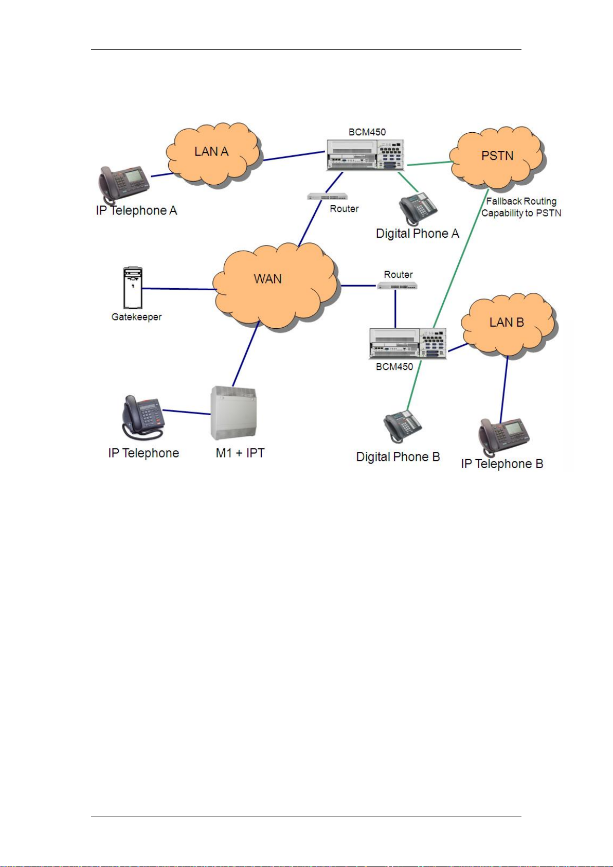
Below is a diagram showing an example of a VoIP Network.
IP Telephony
Key IP Telephony Concepts
In traditional telephony, the voice path between two telephones is circuit
switched. This means that the digital connection between the two telephones
is dedicated to the call. The voice quality is usually excellent, since there is no
other signal to interfere.
In IP telephony, voice quality between IP telephones can vary significantly
from call to call and time of day. When two IP telephones are on a call, each
IP telephone encodes the speech at the handset microphone into small data
packets called frames. The system sends the frames across the IP network to
the other telephone, where the frames are decoded and played at the handset
receiver. If some of the frames get lost while in transit, or are delayed too
long, the receiving telephone experiences poor voice quality.
Codecs
The algorithm used to compress and decompress voice is embedded in a
software entity called a codec (COde-DECode). Two popular Codecs are
G.711 and G.729. The G.711 Codec samples voice at 64 kilobits per second
(kbps) while G.729 samples at a far lower rate of 8 kbps. Voice quality is
NN40011-028 Issue 1.2 BCM Rls 6.0 11
Page 12

IP Telephony
better when using a G.711 CODEC, but more network bandwidth is used to
exchange the voice frames between the telephones.
If you experience poor voice quality, and suspect it is due to heavy network
traffic, you can get better voice quality by configuring the IP telephone to use
a G.729 CODEC.
The BCM supports these codecs:
G.729
G.723
G.729 with VAD (Voice Activity Detection - the transmission of "silent
packets" over the network)
G.723 with VAD
G.711-uLaw
G.711-aLaw
BCM allows for CODEC renegotiation. This means that two sets and/or
trunks using dissimilar CODEC settings, when initiating the VoIP call, would
negotiate and decide which CODEC to use. In earlier BCM software levels,
differing CODECS would have meant that the call would be dropped.
Jitter Buffer
Voice frames are transmitted at a fixed rate, because the time interval
between frames is constant. If the frames arrive at the other end at the same
rate, voice quality is perceived as good. In many cases, however, some
frames can arrive slightly faster or slower than the other frames. This is called
jitter, and degrades the perceived voice quality. To minimize this problem,
configure the IP telephone with a jitter buffer for arriving frames.
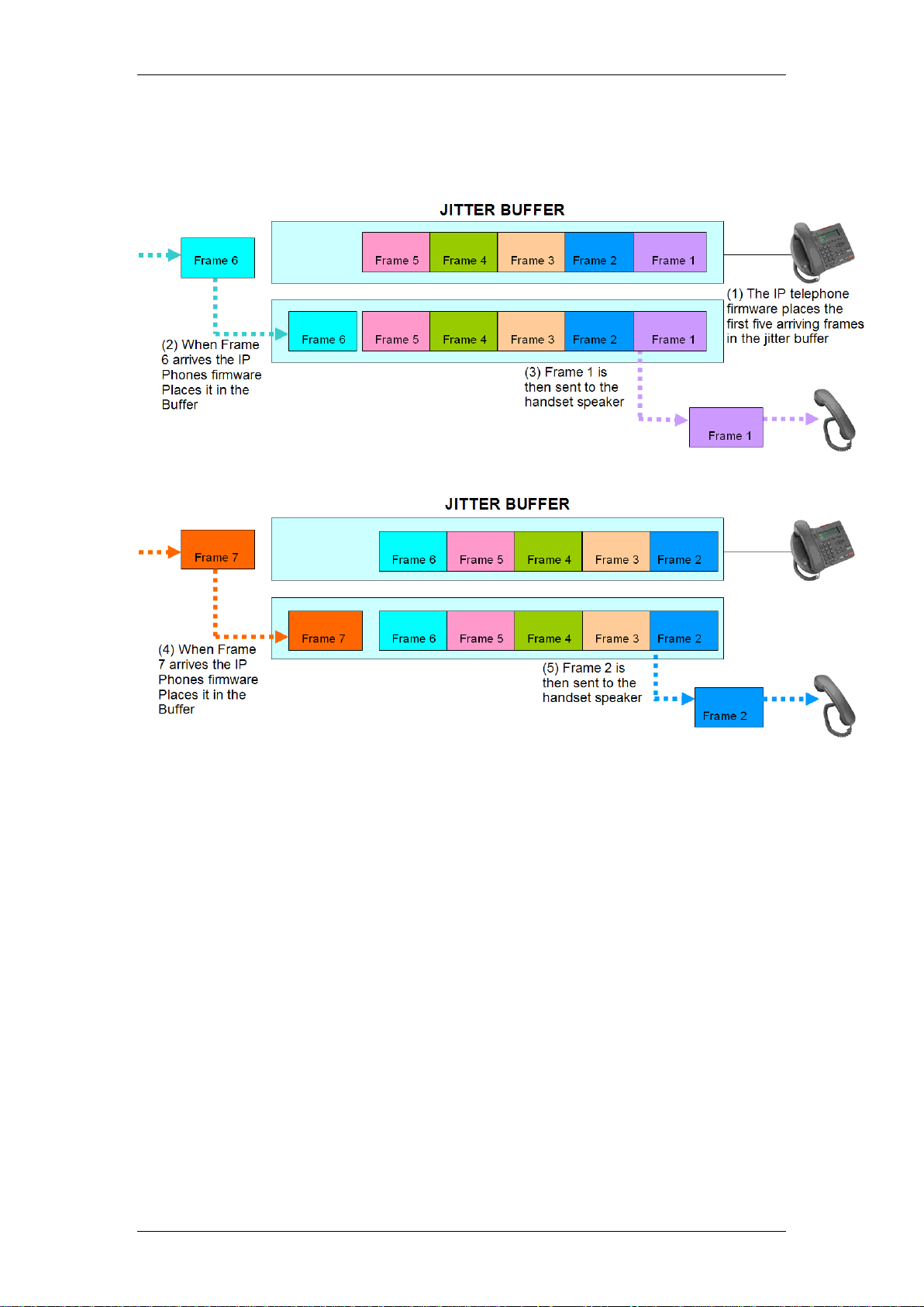
This is how the jitter buffer works - Assume a jitter buffer setting of five
frames:
The IP telephone firmware places the first five arriving frames in the
jitter buffer.
When frame six arrives, the IP telephone firmware places it in the
buffer, and sends frame one to the handset speaker.
When frame seven arrives, the IP telephone buffers it, and sends frame
two to the handset speaker.
The net effect of using a jitter buffer is that the arriving packets are
delayed slightly in order to ensure a constant rate of arriving frames at
the handset speaker.
12 NN40011-028 Issue 1.2 BCM Rls 6.0
Page 13
IP Telephony
The below diagram shows a Jitter Buffer example assuming a jitter buffer
setting of five frames:
Possible jitter buffer settings and corresponding voice packet latency (delay)
for the BCM system IP telephones are:
None
Small (G.711/G.729: 0.05 seconds)
Medium (G.711/G.729: 0.09 seconds)
Large (G.711/G.729: 0.15 seconds)
NN40011-028 Issue 1.2 BCM Rls 6.0 13
Page 14
IP Telephony
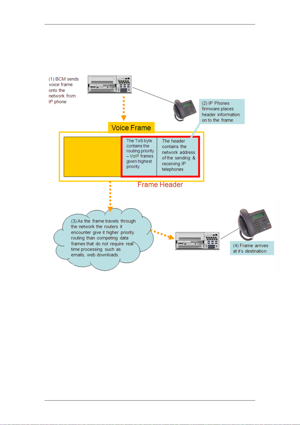
QoS Routing
The process of prioritizing data frames is referred to as Quality of Service
(QoS) routing.
The BCM system supports QoS routing, when it is integrated with other Avaya
routing solutions. The BCM system can also be configured to monitor QoS so
that the system reverts to a circuit-switched line if a suitable QoS cannot be
guaranteed.
VoIP packets can also be “marked” using DSCP, with the aim of prioritising
these packets through the network.
Remote Working Capability
The latest release of BCM offers the option of being able to use an IP
Telephone in remote locations, as it were a phone on the local system. The
Remote Worker solution only requires standard routers and networking
capability to perform this function. If necessary, the IP telephone can be
moved to various locations as required, as long as there is network access to
the BCM.
14 NN40011-028 Issue 1.2 BCM Rls 6.0
Page 15

IP Telephony
A typical example of the Remote Worker solution would be a home worker
who wishes to connect an IP telephone to the main office BCM, using their
standard home router and the internet. The office BCM would be connected to
the internet via a router which has a static public IP address, and forwards the
IP telephone‟s data/voice traffic to the BCM (and vice-versa).
Alternatively, if extra security is required for the data/voice traffic, a VPN
connection can be initiated via the 1120 and 1140 IP telephones. This
requires enhanced IP phone configuration, and a VPN router at the main
office hosting the BCM.
Required Information
Before configuring IP Telephony, the following information will need to be
confirmed:
Which interface will be used for the Published IP address?
Is there a Gatekeeper connected to the BCM, if so, what is the IP
address of the Gatekeeper and the Alias name for the BCM?
If there is no Gatekeeper, what are the IP addresses of the remote
Gateways and what are the telephony destination digits required to dial
those systems?
What password will be used for IP Phone registration?
Are there any routers that should be referenced as part of the VoIP
configuration? These may be used to provide WAN access for
example.
If using the Remote Worker or 1100 series VPN solutions, what is the
public IP address of the router connecting the BCM to the
Internet/WAN network.
What telephony configuration is required for IP Telephony?
Will DHCP be required for the IP Phones, and if so, will the BCM be set
up to provide IP Addresses to the phones?
NN40011-028 Issue 1.2 BCM Rls 6.0 15
Page 16
IP Telephony
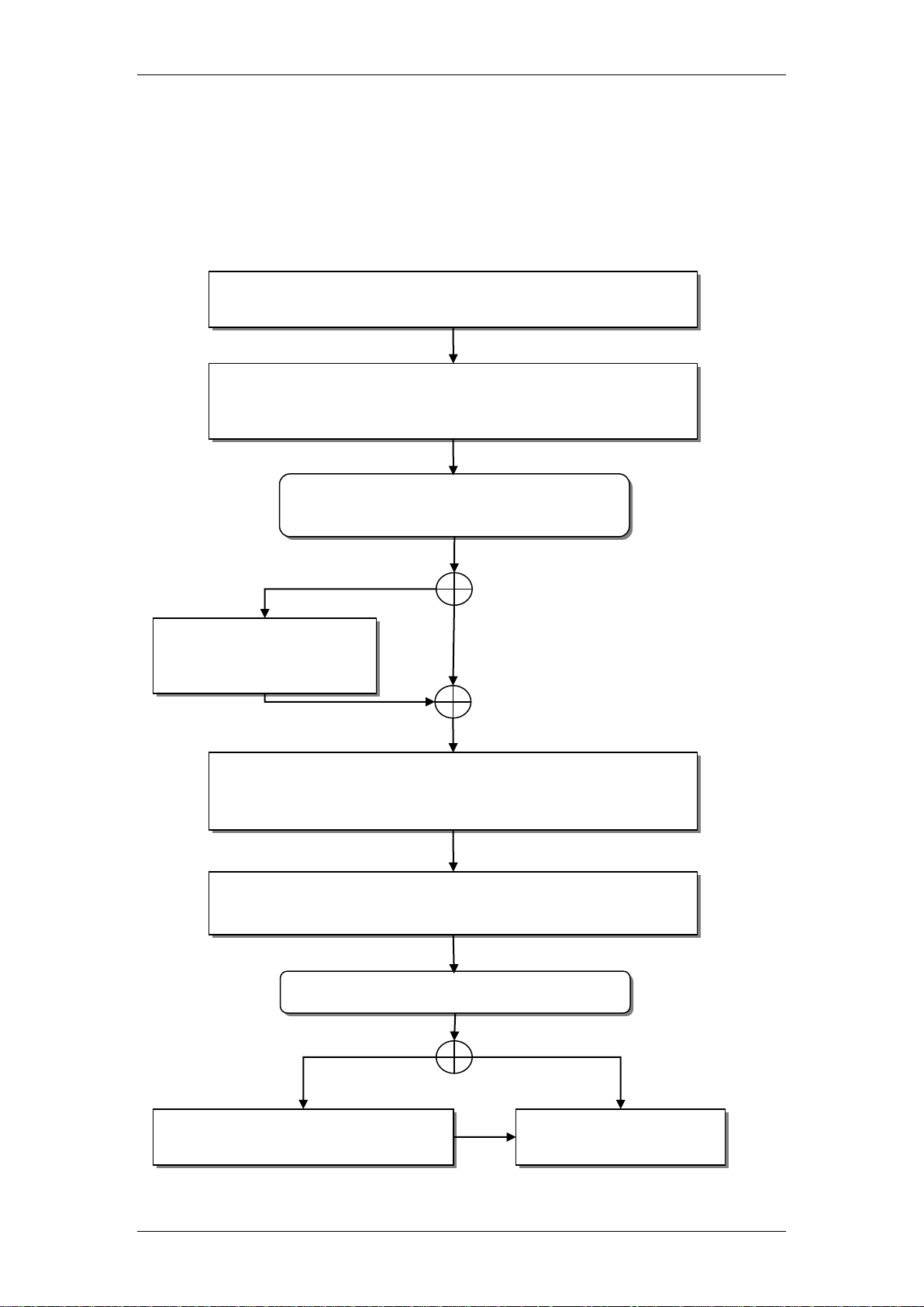
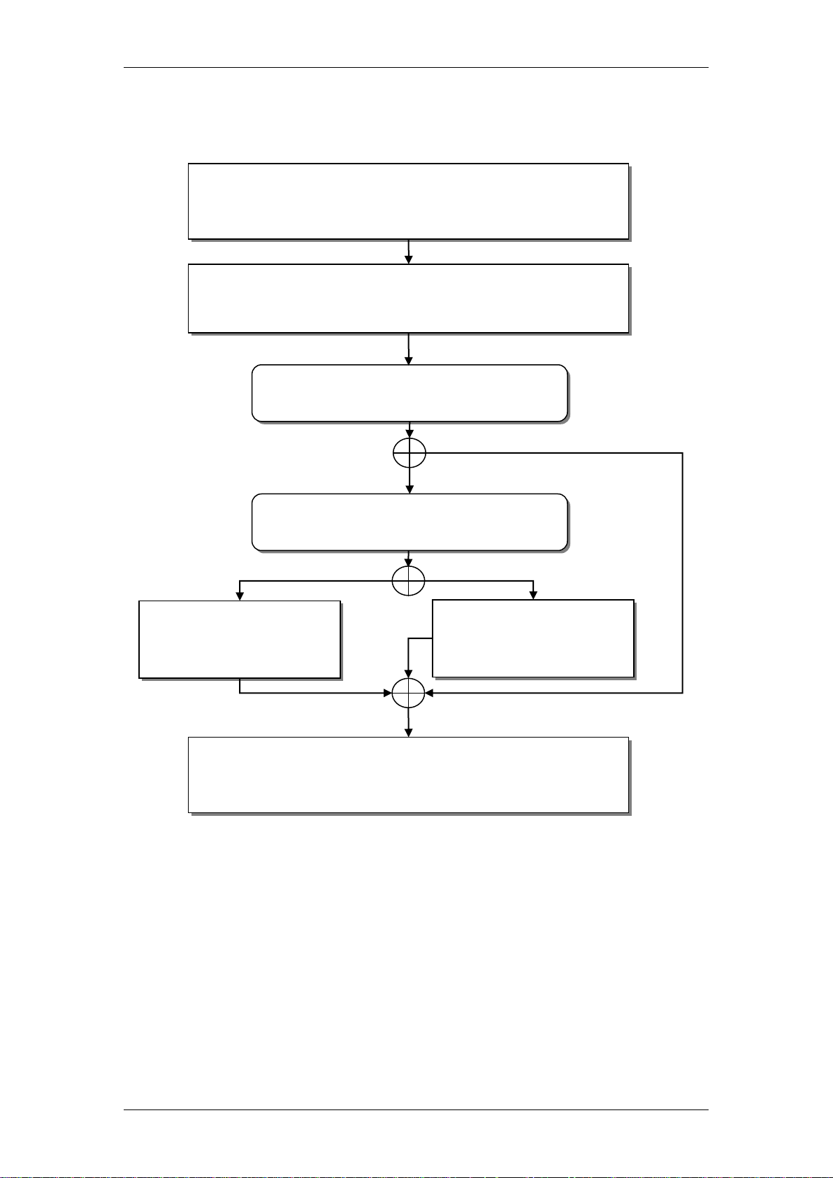
Will the BCM be used to issue IP
Addresses to the IP phones?
Ensure that the required keycodes are applied to the
BCM: refer to the Keycodes section of this guide.
Set the BCM‟s IP Address that the IP phones will
register against: refer to the Published IP Interface
section of this guide.
Refer to the DHCP
Configuration section
of this guide.
Register the IP phones: refer to the Registering the IP
Phones to the System section of this guide.
Will the 2050 IP Softphone be used?
Refer to the 2050 IP Softphone
section of this guide.
IP Phones have been
configured for use.
Yes
No
Yes
No
Set the BCM up to allow IP phones to register:: refer to
the Preparing Your system for IP Telephone
Registration section of this guide.
Flow Charts
Use the following flow charts to determine which sections of this guide to use.
IP Telephone Configuration
16 NN40011-028 Issue 1.2 BCM Rls 6.0
Page 17
VoIP Gateway Configuration
Will SIP be used over the VoIP
trunks?
Determine how incoming and outgoing calls will be
handled: refer to the Configuring the Local Gateway
Settings section of this guide.
Check the H323 and/or SIP Media Parameters: refer to
the H323 & SIP Media Parameters section of this
guide.
Refer to the Private SIP
Specific Configuration
section of this guide.
If not using a Gatekeeper on the network, manually
configure the Remote Gateways: refer to the Remote
Gateways (Routing Table) section of this guide.
Yes
No
Will the SIP trunks be private to
another system, or public to an ITSP?
Refer to the Public SIP
Trunk Configuration
section of this guide.
Private
Public to ITSP
IP Telephony
NN40011-028 Issue 1.2 BCM Rls 6.0 17
Page 18
IP Telephony
General Configuration
The BCM supports the following IP telephony protocols: UNISTIM, H.323 and
SIP.
The IP telephones use UNISTIM.
The Symbol NetVision and NetVision Data telephones use H.323+.
VoIP Trunks can use either H.323 or SIP (defined on a per gateway
basis)
The applications that control these protocols on the BCM provide an invisible
interface between the IP telephones and the digital voice processing controls
on the BCM.
Keycodes
The first part of configuration for IP Telephony is ensuring that the required
keycodes have been purchased and are entered.
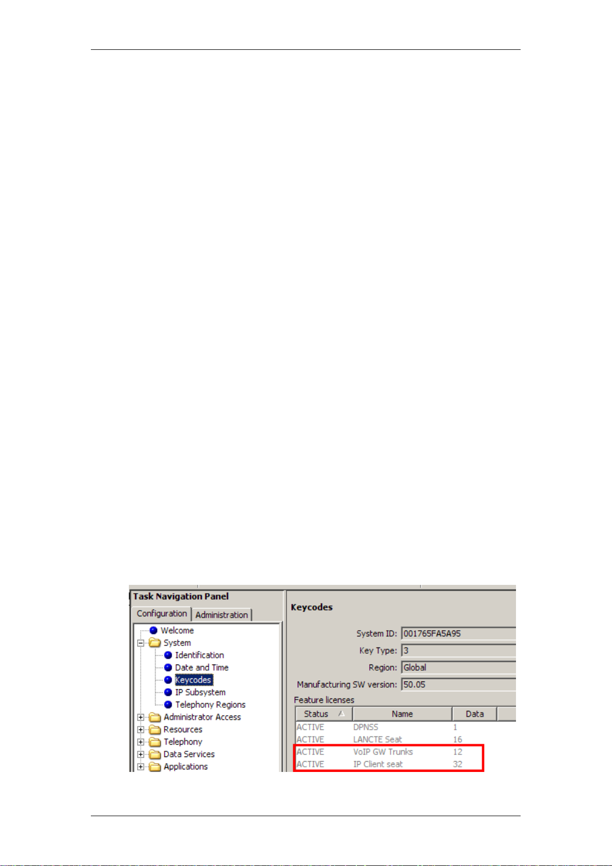
1. In Element Manager, select the Configuration tab and then open the
System folder. Select the Keycodes link and the keycodes that have
been entered will be displayed.
2. Three keycode types are available, depending on your requirements:
VoIP (H.323) or SIP GW Trunks: two trunk protocols for networking
between compatible telephone systems. The number of trunk
licence seats enables determines the maximum number of VoIP
calls that can be placed over VoIP trunks. SIP GW trunks will be
required to connect to ITSPs.
IP Clients: The number of IP Client licence seats determines the
number of IP Phones and Software IP Phones that can be
registered against the BCM.
18 NN40011-028 Issue 1.2 BCM Rls 6.0
Page 19
IP Telephony
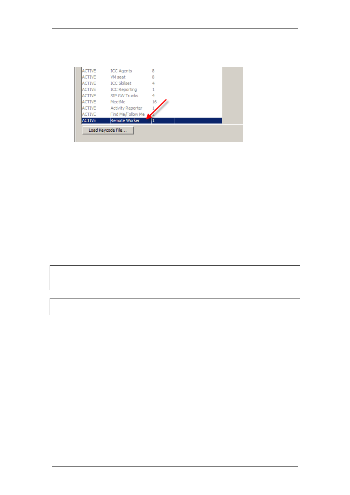
Note: The exception to this rule is when registering telephones to be used
Remote Worker sets. Please refer to the Remote Worker Solution section of
this guide for instructions on S1/S2 assignment for this feature.
Note: The Published IP Address is the address that LAN CTE should also
register against. For further information, refer to the LAN CTE Guide.
Remote Worker: A single keycode unlocks the Remote Worker
solution
Published IP Interface
The Published IP Interface is the IP Address that IP Telephones need to
register against as well as the address that VoIP gateways need to be
“pointed” to. You have the choice of selecting the Customer LAN (refer to the
Configuring the LAN IP Address section of the System Start Up Guide) or
any VLAN IP Addresses (refer to the VLANs Guide) that are configured on
the BCM in the IP Subsystem section of Element Manager.
The Published IP Address must be set as the S1 IP (or S2 IP if the BCM will
be used as a “backup” registration BCM) when configuring IP phones for
registration.
NN40011-028 Issue 1.2 BCM Rls 6.0 19
Page 20
IP Telephony
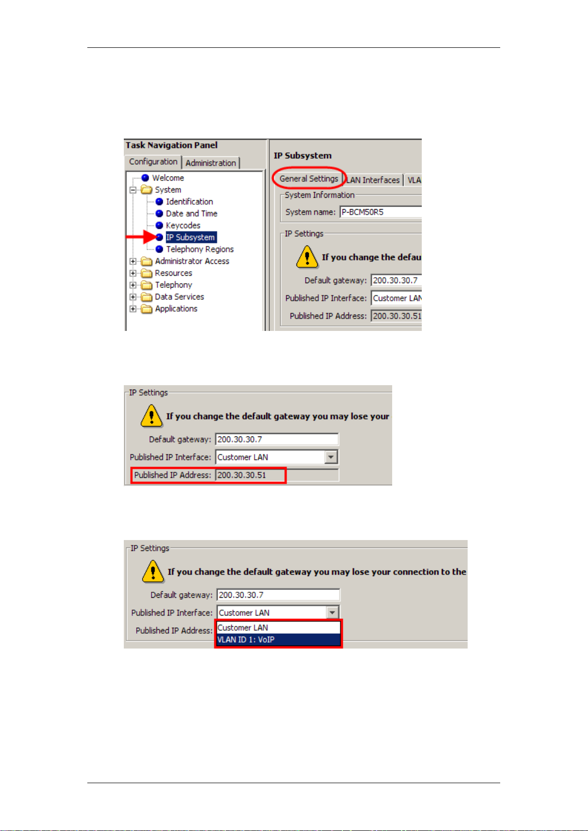
Use the following procedure to check or set the Published IP Address.
1. From the Configuration tab, open the System folder and select IP
Subsystem. Click on the General Settings tab.
2. If checking the existing Published IP Address for IP phone registration
purposes, view the read-only field.
3. If changing the setting, from the Published IP Interface drop-down list,
select the Customer LAN or any of the VLANs configured on the BCM.
20 NN40011-028 Issue 1.2 BCM Rls 6.0
Page 21
IP Telephony
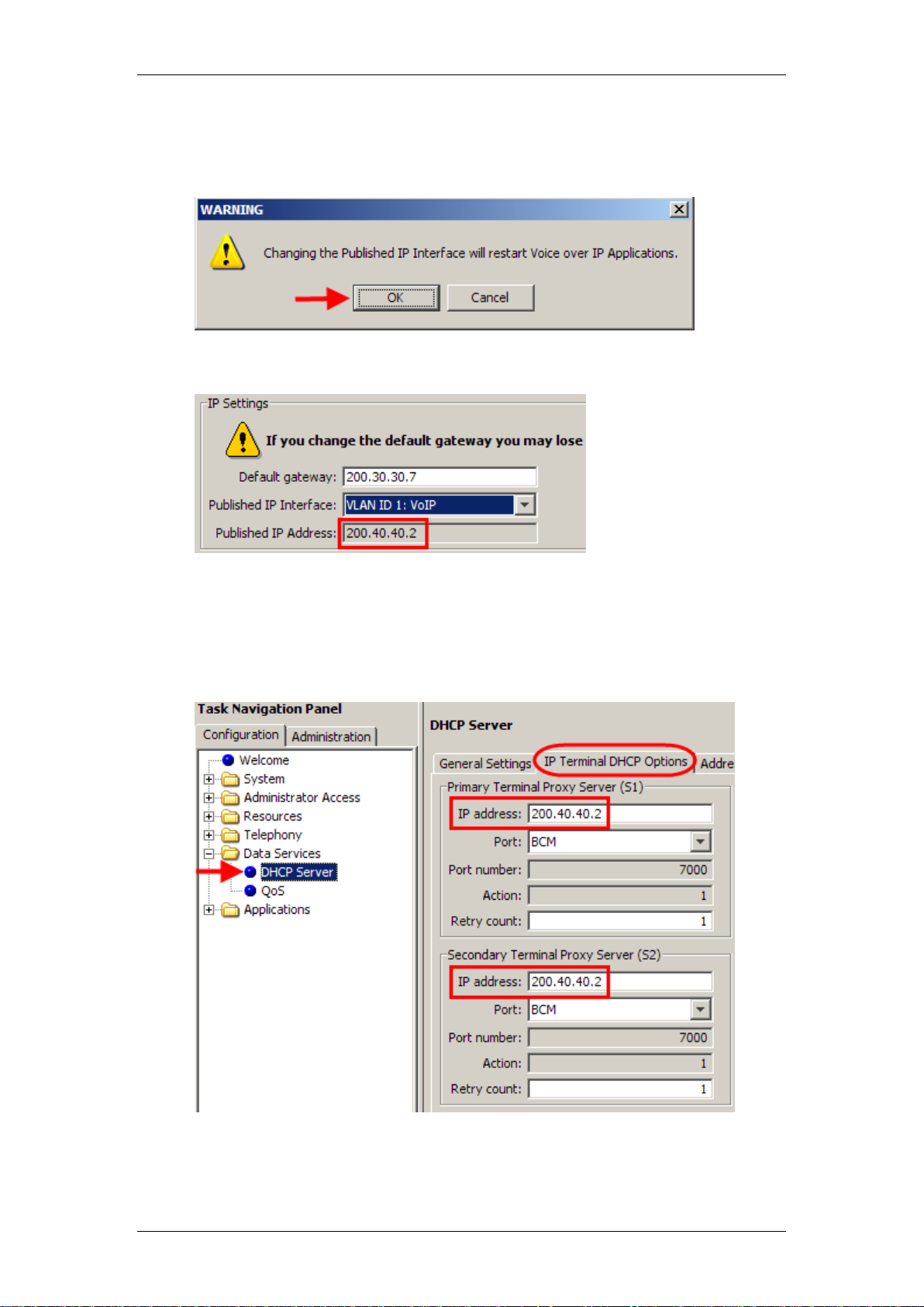
4. A warning box will appear stating that all Voice over IP applications will
be restarted. This may result in VoIP calls being dropped. Click OK to
continue.
5. If changed, the new setting will be displayed,
6. Changing the Published IP Interface setting also has the effect of
changing the S1 Primary Terminal Proxy Server IP Addresses (S1 &
S2) in the DHCP Server IP Terminal DHCP Options screen (refer to the
DHCP Server - IP Terminal Options section of this guide for further
information).
NN40011-028 Issue 1.2 BCM Rls 6.0 21
Page 22
IP Telephony
Attribute
Value
Description
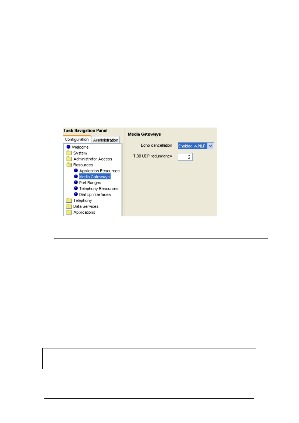
Echo
cancellation
<drop-down
menu>
Enabled w/NLP
Enabled
Disabled
Enable or disable echo cancellation for your system.
Default: Enabled w/NLP (check with your internet system
administrator before changing this)
Echo Cancellation selects what type of echo cancellation is
used on calls that go through a Media Gateway. NLP refers to
Non-Linear Processing.
T.38 UDP
redundancy
<numeric
character string>
If T.38 fax is enabled on the system, this setting defines how
many times the message is resent during a transmission, to avoid
errors caused by lost T.38 messages.
Note: If any network hardware handling network traffic does not support
DSCP, the packets will not be prioritised by that hardware, and will be treated
on an equal basis to non–prioritised packets.
Media Gateways
Certain types of IP communications pass through Media Gateways on the
BCM. You can control the performance of these communications by adjusting
the parameters for echo-cancellation and UDP Redundancy.
The Media Gateways panel allows you to set basic parameters that control IP
telephony.
1. Open the Resources folder and highlight Media Gateways. The
Media Gateways screen will be displayed on the right. Configure the
Parameters as described in the following table.
Media Gateways Settings
Quality of Service (QoS) Settings
The BCM can be configured to mark voice related data packets using the
Differentiated Services Code Point (DSCP) feature, so that they have priority
over other packets on the network. Prioritised packets pass through network
hardware supporting the DSCP feature, ahead of lower priority packets. This
has obvious benefits for real time applications such as Voice over IP.
22 NN40011-028 Issue 1.2 BCM Rls 6.0
Page 23
IP Telephony
Note: Only configure BCM QoS if you have a plan of what types of packets
are prioritised on the network, and the levels (class of service) of priority for
those packet types.
The following types of data packets can be prioritised:
VoIP Signalling (SIP, H.323, and Unistim)
Voice Media
T.38 Fax Media (SIP or H.323)
DSCP Marking
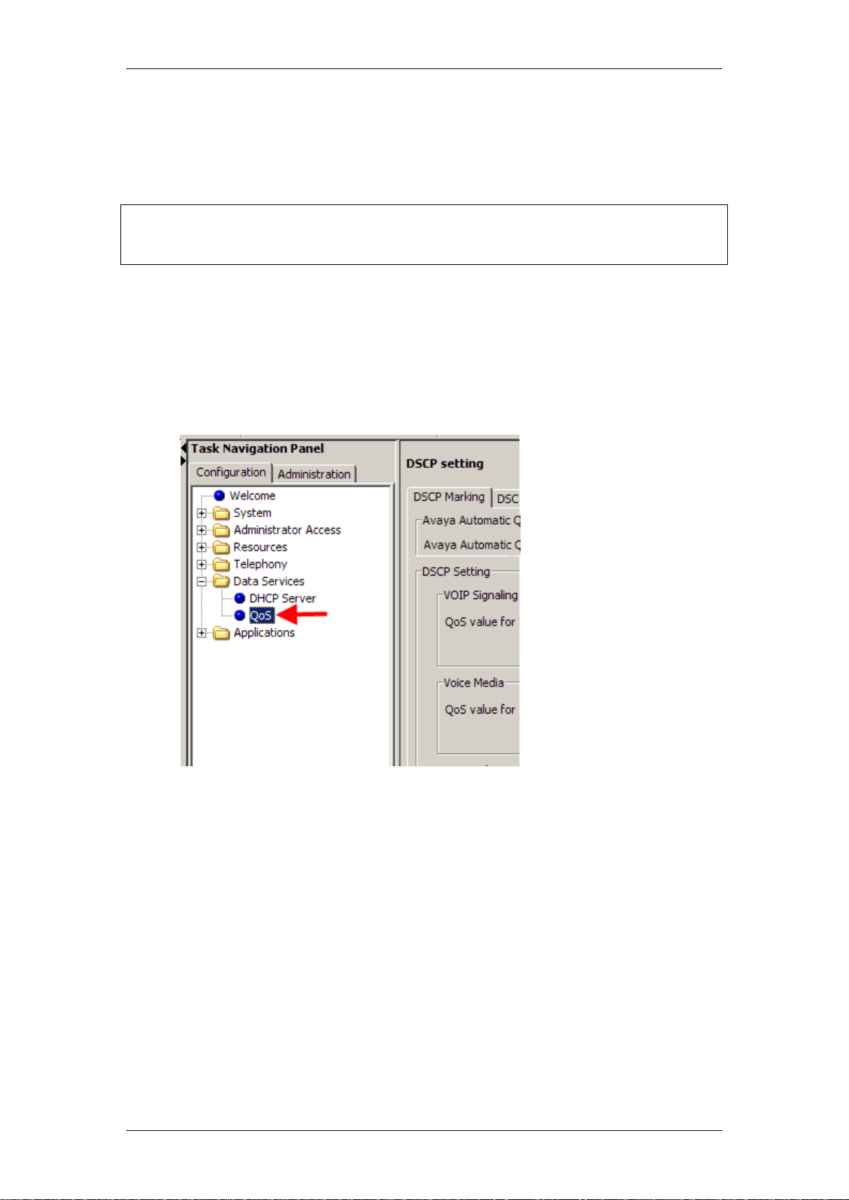
Use the following procedure to set the QoS values for VoIP Signalling, Voice
Media, and Fax Media packets.
1. In Element Manager, select the Configuration tab. Open the Data
Services folder, and click on QoS.
NN40011-028 Issue 1.2 BCM Rls 6.0 23
Page 24
IP Telephony
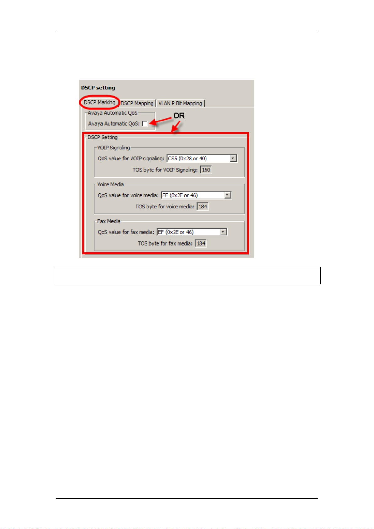
Note: Avaya Automatic QoS should only be used if there are other devices on
the network that support this feature.
2. In the DSCP Marking tab, select either to use Avaya Automatic QoS
settings or select the values for each of VoIP Signalling, Voice Media,
or Fax Media.
3. A value of CUSTOM can also be selected from the drop-down lists,
which will enable a customisable ToS (Terms of Service value) to be
entered.
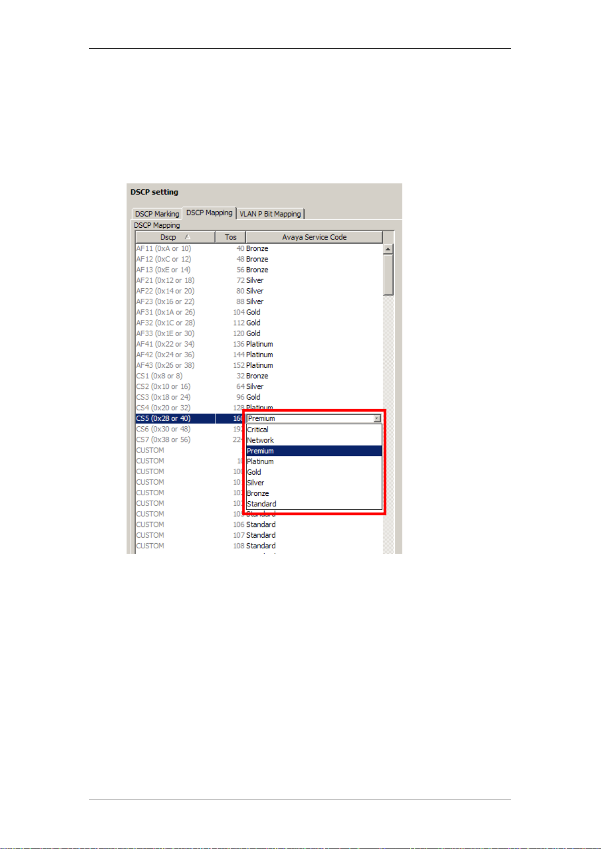
DSCP Mapping
In this area DSCP values are assigned to various service classes. The service
classes determine the priority level of the DSCP value.
The available Service Classes are (in order of priority):
Critical
Network
Premium
Platinum
Gold
Silver
Bronze
Standard
24 NN40011-028 Issue 1.2 BCM Rls 6.0
Page 25
IP Telephony
Therefore, a packet carrying a DSCP value associated with the Critical class
will have the highest priority (assuming the default VLAN P Bit Mapping
settings are not changed).
1. Click on the DSCP Mapping tab. If you want to assign a different
service class to a DSCP value, double-click in the corresponding
Avaya Service Code field and select the class from the drop-down list.
NN40011-028 Issue 1.2 BCM Rls 6.0 25
Page 26

IP Telephony
IP Telephones
IP telephones offer the functionality of regular telephones, but do not require a
hardwire connection to the BCM. Instead, they must be plugged into an IP
network which is connected to the BCM.
Calls made from IP telephones through the BCM can pass over VoIP (H.323
or SIP) trunks or across Public Switched Telephone Network (PSTN) lines.
Avaya provides two types of IP telephones. The IP telephones are wired to an
IP network using Ethernet in the case of the IP telephones, or are accessed
through your desktop or laptop computer, as in the case of the 2050 IP
Softphone.
IP telephones can be configured to the network by the end user or by the
administrator. If the end user is configuring the telephone, the administrator
must provide the user with the required parameters.
DHCP Configuration
Refer to the following sections if the BCM will be used as the DHCP server for
the IP phones.
DHCP Server - IP Terminal Options
If the BCM is configured to pass on DHCP details to IP phones using either
the “Enabled – IP Phones Only” or “Enabled – All Devices” options in DHCP
Server General Settings, then the BCM should be configured to supply the
Primary (S1) and Secondary (S2) Terminal Proxy Server IP Addresses that
the IP Phones should register against.
If the BCM will not be passing on DHCP information to IP Phones, then the IP
Terminal DHCP Options do not require configuring.
Again, if you have configured the Published IP Interface in the Published IP
Interface section, the S1 and S2 will be already set to the Published IP
Address. However, you may wish to check these settings.
Use the following procedure to check or change the IP Terminal DHCP
Options.
26 NN40011-028 Issue 1.2 BCM Rls 6.0
Page 27
IP Telephony
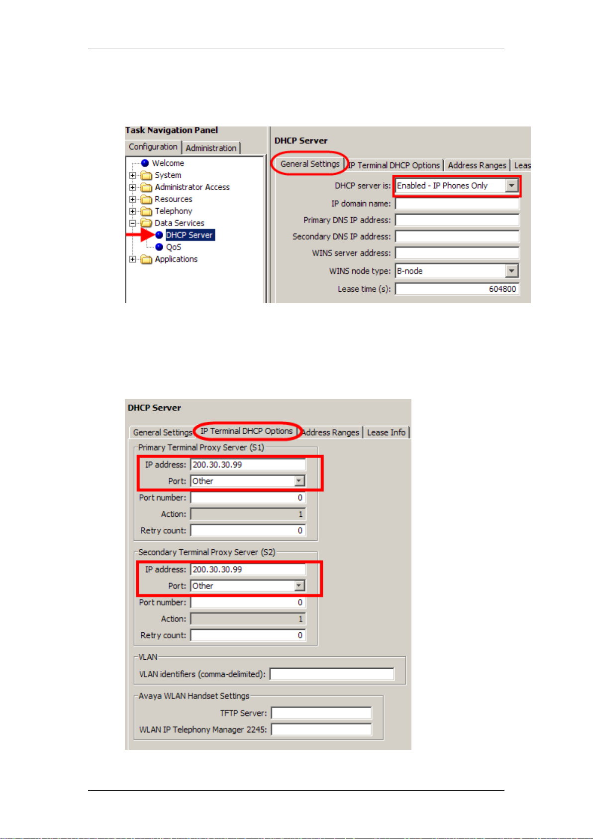
1. From Configuration tab open the Data Services folder and select
DHCP Server. Click on the General Settings tab. Check to see if the
BCM is configured to provide DHCP information to IP Phones.
2. If either Enabled – IP Phones Only or Enabled – All Devices is
selected, then continue with configuring the IP Terminal DHCP
Options.
3. Click on the IP Terminal Options tab.
NN40011-028 Issue 1.2 BCM Rls 6.0 27
Page 28

IP Telephony
Attribute
Value
Description
Primary Terminal Proxy Server (S1)
IP Address
<IP
address>
The IP address of the Proxy Server for IP phones. This should be set
to the BCMs Published IP Address.
Port
<drop-down
list>
Select the appropriate port:
BCM
SRG
Meridian 1/Succession 1000
Centrex/SL-100
Other
Port number
<readonly>
The port number on the terminal through which IP phones connect.
Action
<readonly>
The initial action code for the IP telephone.
Retry count
<number>
The delay before an IP phone retries connecting to the proxy server.
Secondary Terminal Proxy Server (S2)
IP address
<IP
address>
The IP address of the Proxy Server for IP phones. This should be set
to the BCMs Published IP Address, or a backup BCM to register
against.
Port
<drop-down
list>
Select the appropriate port:
BCM
SRG
Meridian 1/Succession 1000
Centrex/SL-100
Other
Port number
<readonly>
The port number on the terminal through which IP phones connect.
Action
<readonly>
The initial action code for the IP telephone
Retry count
<number>
The delay before an IP phone retries connecting to the proxy server.
VLAN
VLAN identifiers
(commadelimited)
Specify the Virtual LAN (VLAN) ID numbers that are given to the IP
telephones.
If you want DHCP to automatically assign VLAN IDs to the IP
telephones, enter the VLAN IDs in the following format:
VLAN-A:id1, id3,…,idn.
Where:
VLAN-A – is an identifier that tells the IP telephone that this message
is a VLAN discovery message.
Id1, id2,…idn – are the VLAN ID numbers that DHCP can assign to
the IP telephones. You can have up to 4 (BCM50) or 8 (BCM450)
VLAN ID numbers listed. The VLAN ID numbers must be a number
from 1 to 4094.
For example, if you wanted to use VLAN IDs 1100, 1200, 1300 and
1400, you would enter the following string in this box: VLAN-A:1100,
1200, 1300, 1400.
If you do not want DHCP to automatically assign VLAN IDs to the
telephones, enter VLAN-A:none, in this text box.
Note1: The Avaya IP Terminal VLAN ID string, must be terminated
with a period (.).
Note2: If you do not know the VLAN ID, contact your network
administrator.
Note3: For information about how to setup a VLAN, refer to the user
4. Ensure that the IP address is set correctly for the Primary and
Secondary Terminal Proxy Servers. Again, these addresses will be
used during the IP Phone registration process. Also, ensure that the
Port is set to BCM. This will automatically set the Port number field to
7000.
5. Configure all other fields as required.
IP Terminal DHCP Options
28 NN40011-028 Issue 1.2 BCM Rls 6.0
Page 29
IP Telephony
Attribute
Value
Description
documentation that came with your VLAN compatible switch, as well
as the VLAN Guide..
Avaya WLAN Handset Settings
TFTP Server
IP Address
Enter the IP Address of the TFTP server that is used for providing
firmware to the WLAN handsets and the 2245 IP Telephony Manager
WLAN IP
Telephony
Manager 2245
IP Address
Enter the IP Address WLAN IP Telephony Manager 2245
Note: Consult with the network administrator to determine a suitable range of
addresses, co-ordinating with the existing network design. For example, it
may be necessary to set up an Address Range for VLANs that host the IP
telephones. For more information on configuring VLANs, please refer to the
VLANs Guide.
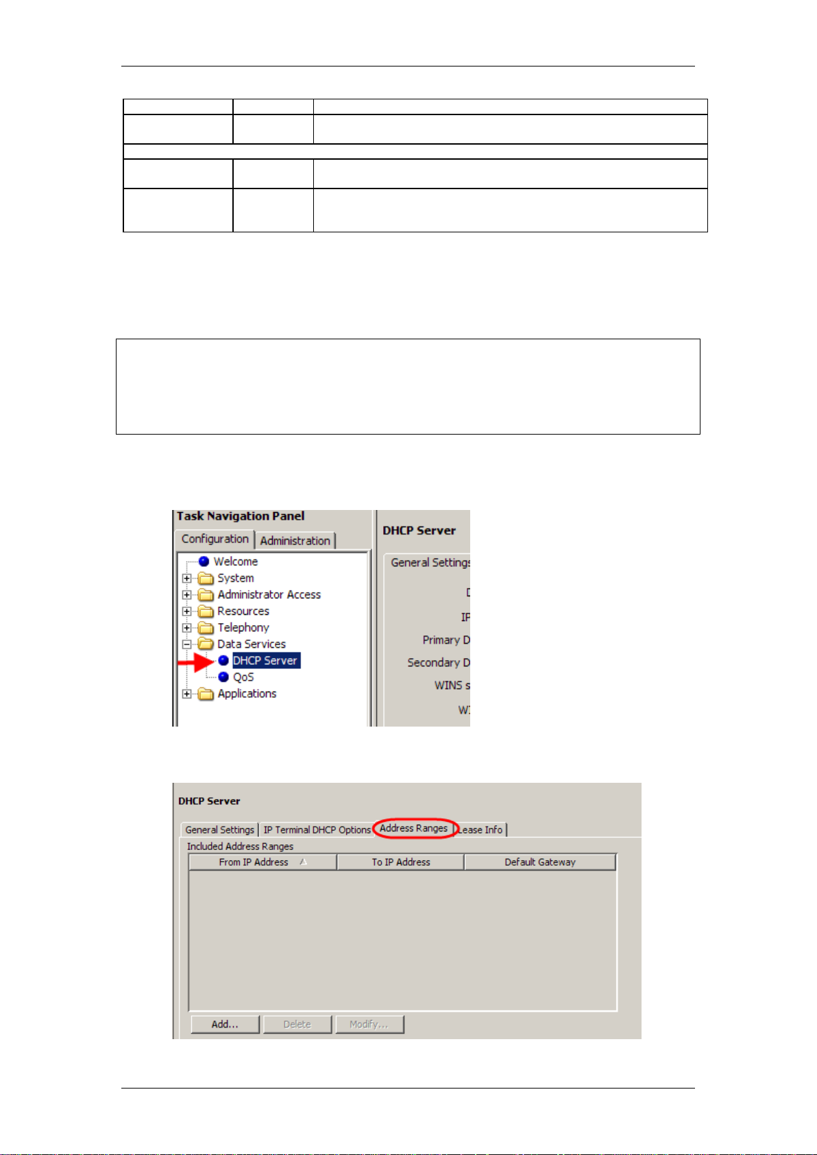
Configuring the DHCP Address Ranges
If the BCM is configured to pass on DHCP information to IP Phones, you
should configure a suitable range of addresses to assign to the IP Phones.
1. In the Configuration panel, open the Data Services folder and select
DHCP Server.
2. Click on the Address Ranges tab.
NN40011-028 Issue 1.2 BCM Rls 6.0 29
Page 30
IP Telephony
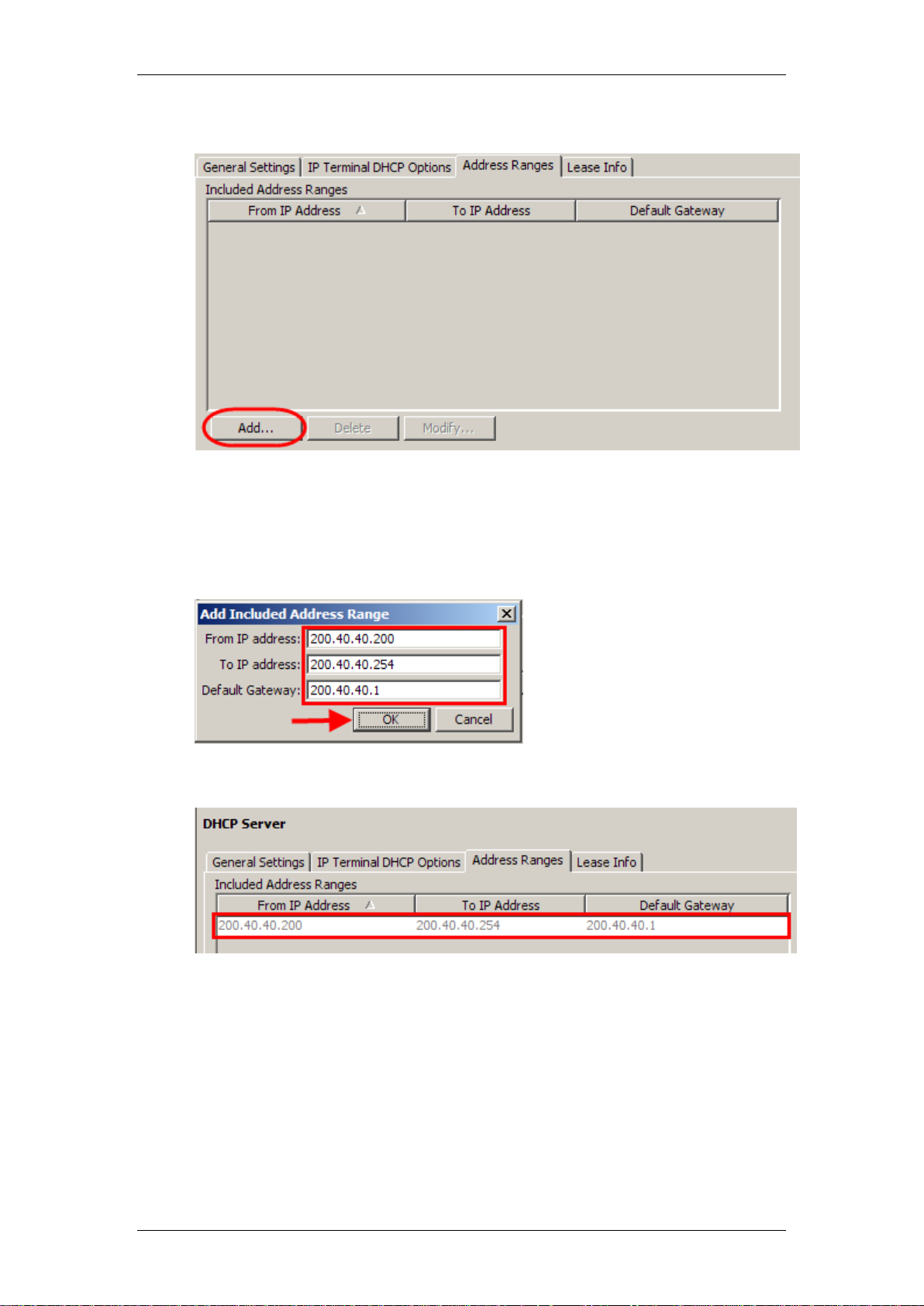
3. If there aren‟t any Address Ranges configured, click on the Add button.
4. Enter the start IP address in the From IP Address field. Enter the end
IP address of the range in the To IP address field. In the Default
Gateway field, enter the IP Address of the network default gateway.
This may be the BCM S1 address in some situations. Click OK to
submit the settings.
5. The new address range will be displayed.
30 NN40011-028 Issue 1.2 BCM Rls 6.0
Page 31

IP Telephony
Preparing Your System for IP Telephone Registration
Before you can register an IP telephone to the BCM, you must activate
terminal registration on the BCM.
1. Open the Resources folder and select the Telephony Resources link
and then select the IP Sets Module Type.
2. Select the IP Terminal Global Settings tab and select the Enable
Registration tick box.
3. If you want the installers to use a single password to configure and
register the telephone, select the Enable global registration
password check box, and then enter a numeric password (the
password will have to be entered on the IP Phone keypad) in the
Global password field.
NN40011-028 Issue 1.2 BCM Rls 6.0 31
Page 32

IP Telephony
Attribute
Value
Description
Enable
registration
<check box>
Select to allow new IP clients to register with the system.
Warning: Remember clear this check box when you have finished
registering the new telephones.
Enable global
registration
password
<check box>
If you want to require the installer to enter a password when IP
telephones are configured and registered to the system, select this
check box.
If this field is left blank, the IP Phone installer may be prompted to enter
the User ID = 738662 and Password = 266344..
Global
password
<10
alphanumeric>
Default: bcmi
(2264)
If the Enable global registration password check box is selected, enter
the password the installer will enter on the IP telephone to connect to
the system.
Auto-assign
DNs
<check box>
If selected, the system assigns an available DN as an IP terminal
requests registration. It does not prompt the installer to enter a set DN.
Note: For this feature to work, Registration must be selected and
Password must be blank.
If not selected, the installer receives a prompt to enter the assigned DN
during the programming session.
Play DTMF
Tone
<check box>
Allows DTMF tones to be sent via VoIP calls.
Advertisement
/Logo
<alphanumeric
string>
Any information in this field appears on the display of all IP telephones.
For example, your company name or slogan.
Default codec
Auto
G.711-aLaw
G.711-uLaw
G.723
G.729
G.729 + VAD
G.723 + VAD
If the IP telephone has not been configured with a preferred codec,
choose a specific codec that the IP telephone will use when it connects
to the system.
If you choose Auto, the IP telephone selects the codec.
If you are unsure about applying a specific codec, ask your network
administrator for guidance.
Default jitter
buffer
None
Auto
Small
Medium
Large
Choose one of these settings to change the default jitter buffer size:
None: Minimal latency, best for short-haul networks with good
bandwidth.
Auto: The system will dynamically adjust the size.
Small: The system will adjust the buffer size, depending on CODEC
type and number of frames per packet to introduce a 60-millisecond
delay.
Medium: 120-millisecond delay
Large: 180-millisecond delay
G.729
payload size
(ms)
10, 20, 30, 40,
50, 60
Default: 30
Set the maximum required payload size, per codec, for the IP telephone
calls sent over H.323 trunks.
Note: Payload size can also be set for IP trunks
G.723
payload size
(ms)
30
G.711
payload size
(ms)
10, 20, 30, 40,
50, 60
Default: 20
4. To automatically assign a DN to the phone being registered, select the
Auto-assign DNs option.
5. Configure all other options as required.
Note: Turn Enable registration and Auto-assign DNs off when the
telephones are registered. Leaving your IP registration open and unprotected
by a password can pose a security risk.
IP Terminal Global Settings
32 NN40011-028 Issue 1.2 BCM Rls 6.0
Page 33

IP Telephony
Attribute
Value
Description
Support
Remote
Worker
<checkbox>
Tick this box to enable the Remote Worker feature. For full information
on this feature, refer to the Remote Worker Solution section of this
guide.
Discovered
Public
Address
<ip address>
Read-only field. Displays the public IP address of the router the BCM is
connected to, if discovered via the STUN protocol. Refer to the Remote
Worker Solution section of this guide for more information.
Provisioned
Public
Address
<ip address>
Read-only field. Displays the public IP address of the router the BCM is
connected to, if manually entered. Refer to the Remote Worker
Solution section of this guide for more information.
Registering the IP Phones to the System
How you configure the telephones depends on whether DHCP is active on the
network. When registering the IP Phones, you have the option of selecting the
DHCP setting most appropriate to the network:
DHCP (Full): The DHCP server will provide the following information to
the IP Phones:
o IP Address & Subnet Mask
o Default Gateway
o S1 & S2 Addresses
o Port Number, Action, & Retry Count
o VLAN ID
Only use DHCP (Full) if the BCM is supplying the DHCP information to
the IP Phones, or the network DHCP server can be configured to
supply this information.
DHCP (Partial): The DHCP Server will provide the following
information to the IP Phones:
o IP Address & Subnet Mask
o Default Gateway
The rest of the required information will have to be entered manually.
DHCP (Partial) is used in situations where the BCM is not acting as the
DHCP server to the phones, but another device is. This can also be
used in scenarios where the IP Phone is on a remote network.
DHCP (Off): All information will have to be entered manually during the
registration process. Use this in situations where there isn‟t a DHCP
server on the network, or you simply want to configure the settings
manually.
When the telephone registers, it downloads the information from the system
IP Telephony record to the telephone configuration record. This can include a
new firmware download, which occurs automatically. If new firmware
downloads, the telephone display indicates the event.
Once registration has completed, you do not need to go through the
registration process again, unless you deregister the terminal.
NN40011-028 Issue 1.2 BCM Rls 6.0 33
Page 34

IP Telephony
Display Keys
COLOR*SET
If booting up a new phone for the first time, you may be immediately prompted
to enter a password. If this is the case, enter COLOR*SET (26567*738)
followed by OK. You can then proceed with the registration process.
Configuring Telephone Settings
If you are not automatically registered to the BCM, you can configure your
telephone settings to allow you to access a BCM on the network. You will also
need to perform these steps if your IP telephone is not connected to the same
LAN that the BCM is connected to.
Access the configuration parameters using the method described for the
model of phone, and then configure the parameters to enable phone
registration.
Accessing the Configuration Parameters – i2001, i2002, i2004
1. Restart the telephone by disconnecting the power, then reconnecting the
power. After about four seconds, the top light flashes and the text Avaya
appears on the screen.
2. When the greeting appears, quickly press the four display keys, one at a
time, from left to right. These keys are located directly under the display.
These keys must be pressed one after the other within 1.5 seconds or the
telephone will not go into configuration mode.
3. If the display shows EAP Enable you have successfully accessed the
configuration parameters. Proceed with configuring the parameters to
enable phone registration.
Note: Use OK to access the next menu item.
34 NN40011-028 Issue 1.2 BCM Rls 6.0
Page 35

IP Telephony
Display Keys
Accessing the Configuration Parameters – i2033
1. Restart the telephone by disconnecting the power, then reconnecting the
power. After about 15 to 20 seconds, the top light flashes and the text
Avaya appears on the screen.
2. When the greeting appears, quickly press the three display keys, one at a
time, from left to right. These keys are located directly under the display.
These keys must be pressed one after the other within 1.5 seconds or the
telephone will not go into configuration mode.
3. If the display shows EAP Enable you have successfully accessed the
configuration parameters. Proceed with configuring the parameters to
enable phone registration.
Note: Use OK to access the next menu item.
Accessing the Configuration Parameters – i2007
1. Restart the telephone by disconnecting the power, then reconnecting the
power. After about four seconds, the top light flashes and the text Avaya
appears on the screen.
2. When the phone has started, press the Tool icon once.
3. Select Network Configuration from the menu.
4. If the display shows EAP Enable you have successfully accessed the
configuration parameters. Proceed with configuring the parameters to
enable phone registration.
Note: Navigation is performed by the navigation cluster at the bottom of the
phone. You can also use the pointing device as the screen is touch sensitive.
NN40011-028 Issue 1.2 BCM Rls 6.0 35
Page 36

IP Telephony
Services Key
Accessing the Configuration Parameters – 1110, 1120e, 1140e
1. Restart the telephone by disconnecting the power, then reconnecting the
power. After about 15 to 20 seconds, the top light flashes and the text
Avaya appears on the bottom left of the screen.
2. Wait a further 15 – 20 seconds. Press the Services ( ) key
twice. A menu will display.
3. Select Network Configuration, either by pressing the associated keypad
number, or by using the navigation cluster.
4. If the display shows EAP Enable you have successfully accessed the
configuration parameters. Proceed with configuring the parameters to
enable phone registration.
Note: Navigation is performed by the navigation cluster in the center of the
phone. The central button is the Enter or OK key.
36 NN40011-028 Issue 1.2 BCM Rls 6.0
Page 37

IP Telephony
Services Key
Accessing the Configuration Parameters – 1210, 1220, 1230
1. Restart the telephone by disconnecting the power, then reconnecting the
power. After about 15 to 20 seconds, the top light flashes and the text
Avaya appears on the bottom left of the screen.
2. Wait a further 15 – 20 seconds. Press the Services ( ) key
twice. A menu will display.
3. Select Network Configuration, either by pressing the associated keypad
number, or by using the navigation cluster.
4. If the display shows EAP Enable you have successfully accessed the
configuration parameters. Proceed with configuring the parameters to
enable phone registration.
Note: Navigation is performed by the navigation cluster in the center of the
phone. The central button is the Enter or OK key.
NN40011-028 Issue 1.2 BCM Rls 6.0 37
Page 38

IP Telephony
Note: The below options may differ slightly on certain phone models.
Field
Value
Description
DHCP
0 or 1
Enter 0 if not using a DHCP server to dispense IP addresses.
Enter 1 if using a DHCP server.
If you choose to use the Full DHCP server option rather than
allocating static IP addresses for the IP telephones, skip the
remainder of this section.
DHCP Partial
0 or 1
Only appears if DHCP is selected. Enter 0 for Full DHCP or 1 for
Partial DHCP.
SET IP
<ip address>
The set IP must be a valid and unused IP address on the
network that the telephone is connected to. (refer to Network
Administrator)
NETMASK
<subnet mask
address>
This is the subnet mask. This setting is critical for locating the
system you want to connect to. (refer to Network Administrator)
DEF GW
<ip address>
Default Gateway on the network (i.e., the nearest router to the
telephone. The router for IP address W.X.Y.Z is usually at
W.X.Y.1). If there are no routers between the telephone and the
BCM network adaptor to which it is connected, (for example a
direct HUB connection), then enter the Published IP address of
the BCM as the DEF GW.
If the IP telephone is not connected directly to the Published IP
address network adaptor, set the DEF GW to the IP address of
the network adaptor of the router the telephone is connected to.
(refer to Network Administrator)
S1 IP
<ip address>
This is the Published IP address of the first BCM that you want
to register the telephone to. (refer to Network Administrator)
S1 PORT
Default: 7000
This is the port the telephone will use to access this BCM.
S1 ACTION
Default: 1
S1 RETRY
COUNT
<digits between 0
and 255>
Set this to the number of times you want the telephone to retry
the connection to the BCM.
S2 IP
<ip address>
This is the Published IP address of the second BCM that you
want to register the telephone to. It can also be the same as the
S1 setting. (refer to Network Administrator)
S2 PORT
Default: 7000
This is the port the telephone will use to access this BCM.
S2 ACTION
Default: 1
S2 RETRY
COUNT
<digits between 0
and 255>
Set this to the number of times you want the telephone to retry
the connection to the BCM.
VLAN
0: No VLAN
1: Manual VLAN
2: Automatically
discover VLAN
using DHCP
If you have DHCP set to yes, you can select number 2 if you
want the system to find the VLAN port assigned to the
telephone.
If you do not have DHCP, or if you want to set the VLAN port
number manually, select number 1.
If VLANs are not used on your network, select 0.
Cfg XAS?
0: No (default)
1: Yes
If you want to enable connection to a Net6 service provider
server, choose 1. You are then prompted for an IP address for
the server.
IP Telephone Configuration Parameters – (On Phone’s
Display)
Note: Only the settings below are required to allow the IP Telephone to be
registered. Accept the defaults for all other settings.
Note: To enter a full stop () when specifying an IP Address or Subnet Mask,
use the key on the dialpad.
When you have entered all the configuration information, the telephone
attempts to connect to the BCM. The message Locating Server appears on
the display. If the connection is successful, the message changes to
38 NN40011-028 Issue 1.2 BCM Rls 6.0
Page 39

IP Telephony
Connecting to Server after about 15 seconds. Initialisation may take several
minutes. Do not disturb the telephone during this time.
Once the telephone connects to the server, the display shows the DN number
and a date display. Alternatively, if the Auto Assign DNs option is disabled
(refer to the Preparing Your System for IP Telephone Registration section
of this guide) you will be prompted to enter a DN for the telephone.
Note: You will be prompted to enter a password. Enter the registration
password (i.e. the Global Registration Password described in the
Preparing Your System for IP Telephone Registration section of this
guide) and press the OK soft key. Alternatively, if the Global Registration
Password is not enabled, you may be prompted to enter the following
information: Registration: SETNNA = 738662 Password: CONFIG = 266344
Note: Each of the IP Telephones can be configured with the same settings as
a standard digital handset. With this in mind, each needs to be assigned
Lines and / or Line pool access granted. For information on these settings,
please refer to the Telephony Services Guide.
NN40011-028 Issue 1.2 BCM Rls 6.0 39
Page 40

IP Telephony
Message
Description and solution
SERVER: NO PORTS LEFT
The system has run out of ports (license seats). This message
remains on the display until a port becomes available and the
telephone is powered down and then up. To obtain more ports,
you can apply additional IP Client keycodes.
Invalid Server Address
The S1 is incorrectly configured with the IP address of a system
network adapter other than the published IP address.
IP Address conflict
The telephone detected that a device on the network is currently
using the IP address allocated to the telephone.
Registration Disabled
The Registration on the system is set to OFF.
SERVER UNREACHABLE.
RESTARTING
Check that you have entered the correct Netmask and gateway
IP addresses. If the settings are correct, contact your system
administrator.
NEW SET
The telephone has not been connected to the system before,
and must be registered.
Problem
Suggested solution or cause
Telephone does not connect to
system
If an IP telephone does not display the text Connecting to
server within two minutes after power up, the telephone did not
establish communications with the system. Double-check the IP
configuration of the telephone and the IP connectivity to the
system (cables, hubs, and so on).
Slow connection between the
handset and the system
If the connection between the IP client and the system is slow
(ISDN, dialup modem), change the preferred CODEC for the
telephone from G.711 to G.729.
One-way or no speech paths
Signaling between the IP telephones and the system uses the
system port 7000. However, voice packets are exchanged using
the default RTP ports
28000 through 28255 at the BCM, and ports 51000 through
51200 at the IP telephones. If these ports are blocked by the
firewall or NAT, you will experience one-way or no-way speech
paths.
Change the contrast level
When an IP telephone is connected for the first time, the contrast
level is set to the default setting of 1. Use FEATURE *7 and the
UP or DOWN key to adjust the contrast.
Block individual IP sets from
dialling outside the system.
If you want to block one or more IP telephones from calling
outside the system, use Restriction filters, and assign them to the
telephones you want to block. Restriction filters are set up under
Configuration > Telephony > Call Security > Restriction
Filters.
Troubleshooting IP Telephones
If a problem is encountered when IP phone attempts to register with the BCM
you may see a number of messages appear on the telephones display. These
are outlines as follows:
40 NN40011-028 Issue 1.2 BCM Rls 6.0
Page 41

IP Telephony
Deregistering IP Telephones
You can deregister selected IP telephones from the system, and force the
telephone to go through the registration process again. You can access the
deregister button from two locations:
1. Select the Configuration tab and open the Resources folder then
select Telephony Resources.
2. Select the IP Sets bus (Configured Device column) and click on the IP
Terminal Details tab. Select the required DN, and click on the
Deregister button.
NN40011-028 Issue 1.2 BCM Rls 6.0 41
Page 42
IP Telephony
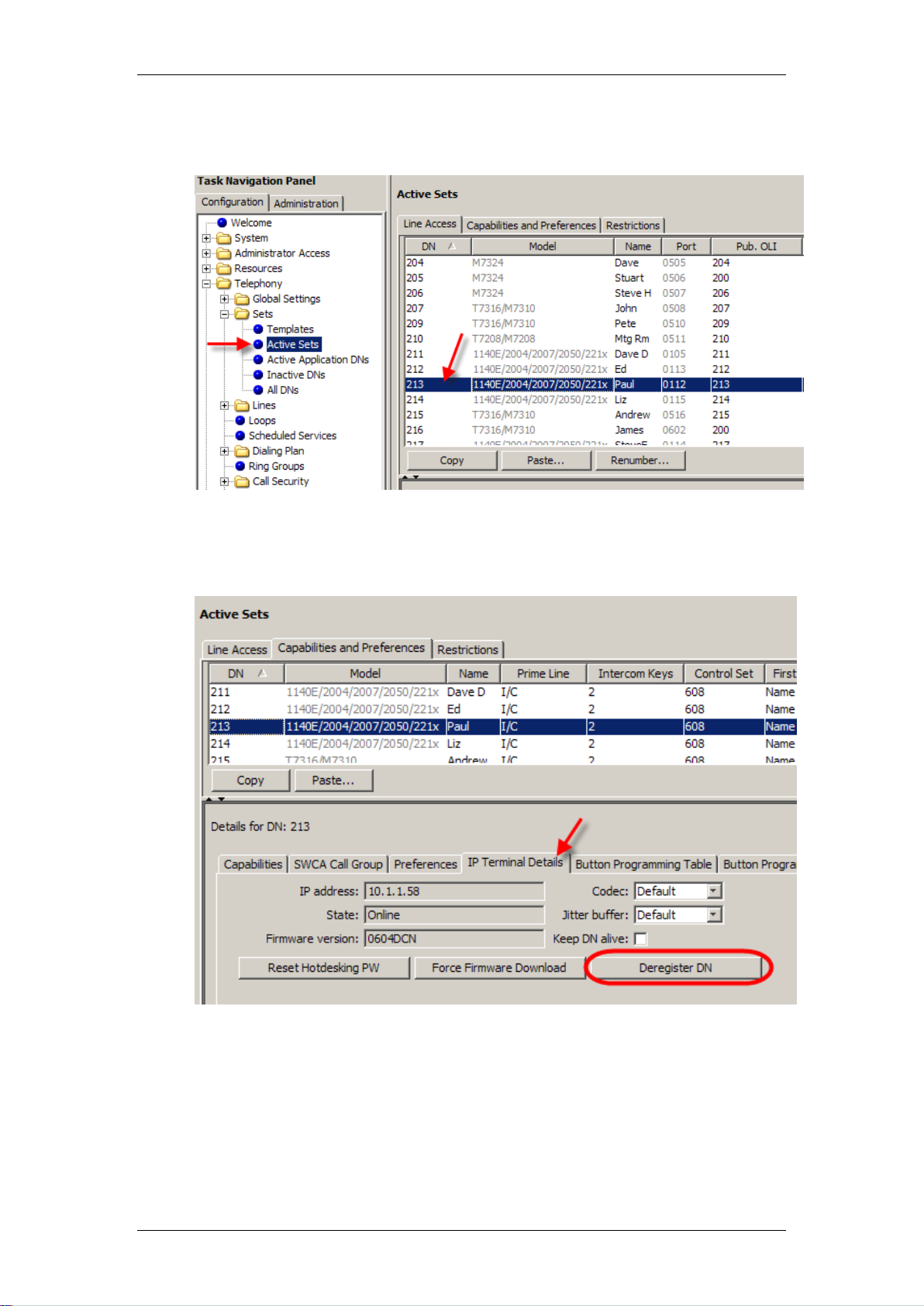
3. Alternatively open the Telephony folder, the Sets folder and highlight
Active Sets. Select the DN you wish to deregister.
4. Click the Capabilities and Preferences tab, followed by the IP
Terminal Details tab in the lower Details part of the screen. Then click
the Deregister button.
42 NN40011-028 Issue 1.2 BCM Rls 6.0
Page 43

IP Telephony
Remote Worker Solution
The Remote Worker solution provides an option for home workers, or BCM
users operating on the outside of the BCM‟s network, to connect an IP Phone
to the BCM. This solution does not require a VPN, and uses NAT to redirect
IP Phone traffic between the connecting networks.
As the Remote Worker solution does not use a VPN (Virtual Private Network),
the traffic is not encrypted, although the proprietary binary format is a form of
simple encryption.
Example Scenario and Configuration Overview
Detailed below is a simple form of the Remote Worker solution. A BCM user
has a home network, and wishes to connect their IP Phone to the office BCM
via the internet.
NN40011-028 Issue 1.2 BCM Rls 6.0 43
Page 44

IP Telephony
The following configuration steps are required for the above scenario:
1. The BCM has to be configured with the office router as the Default
Gateway and with the router‟s public IP Address as the Provisioned
Public Address to ensure that network traffic to the remote worker
phone is correctly addressed. Additionally, the necessary entitlements
of Remote Worker keycode, Support Remote Worker and Enable
Registration options are required to ensure the remote phone can
register and function on the BCM. The port ranges listed above are
configured as default.
2. Next, the office router requires NAT/PAT configuration so that the
desired traffic types (IP Phone signalling and media (voice traffic)) are
routed correctly to and from the BCM. In conjunction with NAT/PAT
configuration, the Firewall should allow the same ports opening
otherwise traffic destined for those ports will be blocked.
3. When the previous steps have been performed the IP Phone will be
able to register on the BCM, using the office router‟s public address as
the primary (S1) and secondary (S2) registration server addresses.
BCM Configuration
1. Launch Element Manager and connect to the BCM.
2. First, check that the Remote Worker keycode has been applied to the
BCM. In the Configuration tab, open the System folder, click on
Keycodes and search for the Remote Worker item.
44 NN40011-028 Issue 1.2 BCM Rls 6.0
Page 45

IP Telephony
3. If Remote Worker is not listed in the Feature Licenses table, contact
your keycode supplier for a keycode file containing this feature and
apply the file to the BCM by clicking on the Load Keycode File…
button.
4. Check that the BCM‟s Published IP Address and Default Gateway are
configured correctly. Under the System folder, click on IP Subsystem.
The Default Gateway should be the LAN address of the office router (in
this scenario). Also, the Published IP Address should be accessible
from the router.
5. These settings should have been configured as part of the System
Start Up process. If they require changing, refer to the Configuring the
LAN IP Address section of the System Start Up Guide.
NN40011-028 Issue 1.2 BCM Rls 6.0 45
Page 46

IP Telephony
6. The Public IP Address of the router now needs to be configured on the
BCM. Under the System folder, click on IP Subsystem. In the Public
Network area click on the Modify button.
7. You can choose to manually enter the public address of the router to
be used in the Remote Worker solution in the Provisioned Public
Address field,
or tick the Address Discovery Flag to attempt to automatically
discover the router public IP address using Stun. To do this, enter the
Stun Server Address in the available field.
46 NN40011-028 Issue 1.2 BCM Rls 6.0
Page 47

8. For either method, click OK when the appropriate details have been
entered. Either the Provisioned Public Address or Discovered
Public Address will be displayed, depending on which Discovery
Setting method was used.
9. Next, the IP Telephony settings require configuration. Open the
Resources folder, click on the Telephony Resources folder and
select IP Sets.
IP Telephony
10. In the Details area in the lower part of the screen, tick the Support
Remote Worker checkbox. Without this option enabled, remote
workers will not be able to connect to the BCM. (You will notice the
Provisioned/Discovered Public Address information as configured
previously.) Click OK on the resulting WARNING screen (refer to the
Remote Worker Security Considerations section for information on
securing the system whilst the Support Remote Worker option is
enabled).
NN40011-028 Issue 1.2 BCM Rls 6.0 47
Page 48

IP Telephony
Note: It is always good practice to disable registration (un-tick the Enable
registration checkbox) when known IP phones have been registered. This
prevents unauthorised phones from registering on the BCM, and using the
system fraudulently.
11. Ensure that the general IP Terminal Registration details are configured
to allow IP Phones to register. Please refer to the Preparing Your
System for IP Telephone Registration section of this guide for full
details.
12. Lastly, check that the signalling and RTP over UDP port ranges are
entered on the BCM. Open the Resources folder and click on Port
Ranges. The corresponding values should be used in the router
configuration. The default values for a BCM50 are shown below. A
BCM450 would have the RTP over UDP ranges of 30000 – 30999.
13. The BCM is now configured for the Remote Worker feature.
48 NN40011-028 Issue 1.2 BCM Rls 6.0
Page 49

IP Telephony
Note: The S1 and S2 addresses entered during the registration process
should be the public address of the router the BCM is connected to (e.g.
217.35.6.35 in the scenario described earlier).
Router Configuration
The office router (in this scenario) will require NAT/PAT configuration to route
the remote worker IP phone signalling and media traffic to and from the BCM.
Also, corresponding firewall configuration will be required to allow the
signalling and media to reach the BCM, and return to the public network.
As previously described the ports that require NAT/PAT and firewall
configuration are as follows:
7000 – 7002
30000 – 30099 (BCM50)
30000 – 30999 (BCM450)
Configuring the Remote IP Phone
The IP should be registered as described in the Registering IP Phones to
the System section of this guide.
Remote Worker Security Considerations
Enabling the Remote Worker feature can leave the BCM vulnerable to
fraudulent use by unauthorised parties. If certain settings are left in their
default state and the public IP address of the router is known, external IP
phones could be registered against the BCM and fraudulent use of BCM
facilities would occur.
To prevent against such fraudulent use, ensure the following security steps
are taken:
Ensure any accounts that have telset programming privileges have
their passwords changed, and that the passwords are changed on a
regular basis. This will help prevent system resources being assigned
to unauthorised remote sets. Refer to the User Management Guide for
details on account management.
Change the default Global Password used for registering the set.
After authorised sets have registered, disable the Enable Registration
option.
2050 IP Softphone
The 2050 IP Softphone (also referred to as the i2050) allows you to use a
computer equipped with a USB headset to function as an IP terminal on the
BCM system. The 2050 IP Softphone uses the computer IP network
connection to connect to the BCM. Designed to look and feel like the desktop
1140 IP phone, there are also two additional compact skins, available in black
and silver.
NN40011-028 Issue 1.2 BCM Rls 6.0 49
Page 50

IP Telephony
The 2050 IP Softphone is an IP Telephony application that allows you to make
calls over the LAN and WAN from your computer. The Software Phone
provides classic telephony services, a local telephone Directory, easy access
to Voice Mail, Caller ID information and multiple telephone lines or line
appearances.
Now included with the 2050 IP Softphone are incoming and disconnect call
popups, and a software Expansion Module which emulates an i2004 Key
Expansion Module with 54 Keys. Calls arriving on keys on the software
Expansion Module do not support incoming and disconnect popups.
The installation files for the 2050 IP Softphone are contained on a CD, which
can be obtained from your BCM supplier, or from www.avaya.com.
Licensing
Each 2050 IP Softphone will require a keycode license seat on the BCM (refer
to the Keycodes section of this guide). Additionally, the 2050 IP Softphone
itself should be licensed, which can be achieved via one of a number of
methods:
1. Using the BCM HTTP server
2. Node-Locked Licensing
3. A Licensing Server
The licensing process detailed in this guide will be the BCM HTTP server.
BCM HTTP Server Licensing
This is perhaps the simplest method of licensing the 2050 IP Softphone.
License files are served from the BCM to the 2050 Softphone, unlocking the
i2050 and enabling full functionality. License files are specific to each
installation of the i2050.
Application of the license via the BCM HTTP server method consists of the
following steps:
1. Install the i2050 on a PC.
2. Obtain the i2050 hardware ID. Your keycode supplier will need this
information.
3. Obtain the license files from your keycode supplier.
4. Upload the license files to the BCM HTTP server.
5. Set the Provisiong Server Protocolfield to HTTP and the URL to the
location of the BCM.
6. Restart the i2050. It will search for the licensing information on the
BCM and install the license, allowing the i2050 to connect to the BCM.
Full steps will be detailed in the Licensing the i2050 Using the BCM HTTP
Server Method section of this guide.
Node-Locked Licensing
Node-locked licenses are specific to each i2050 installed on a specific PC.
Once the licensing file is installed on the PC, the license is valid until the i2050
50 NN40011-028 Issue 1.2 BCM Rls 6.0
Page 51

IP Telephony
is uninstalled. This mechanism negates the need for a Licensing Server to be
installed on the network.
Application of the license via the Node-Locked method consists of the
following steps:
1. Install the i2050 on a PC.
2. Obtain the i2050 hardware ID. Your keycode supplier will need this
information.
3. Obtain the license files from your keycode supplier.
4. Place the .license files in the default location of a TFTP server.
5. Set the TFTP server address in the i2050 Provisioning Server IP
Address field.
6. Restart the i2050. It will search for the .cfg and keycode information
and install the license, allowing the i2050 to connect to the BCM.
For further information concerning the Node-Locked Licensing method, please
consult the Avaya document IP Phones Fundamentals (NN43001-368).
Licensing Server
A Licensing server can be installed on a networked PC, which will allow a
certain amount of i2050s to connect to and function with the BCM. This
method does not require a license to be generated for each i2050 on the
KRS. Instead, a number of seats can be purchased and applied to the
Licensing Server, which will then control the number of i2050s installations
that can connect to the BCM.
If an i2050 is licensed via the Licensing Server method, the i2050 uses a
heartbeat mechanism to validate the license every 2 mins. If the heartbeat is
lost, i.e. the i2050 can‟t connect to the server, the i2050 will try to reconnect 5
times and if the connection cannot be re-established then the i2050 will lose
its licence and hence its connection to the BCM. Therefore, if using a
Licensing Server it is imperative that the PC on which it is installed is available
at all times.
For further information concerning the Licensing Server method, please
consult the Avaya document IP Phones Fundamentals (NN43001-368).
Minimum PC Requirements
Pentium® Pro 200 MHz
256 MB memory or higher
36 MB free hard-drive space (all languages)
USB port
Monitor settings: 16 bit High Colour; 800x600 resolution or higher
Supported Operating Systems
Windows XP SP3
Windows Vista SP2 (32-bit)
Windows 7 (32-bit)
NN40011-028 Issue 1.2 BCM Rls 6.0 51
Page 52

IP Telephony
Note: Please ensure that you have the latest version of the 2050 IP
Softphone. Earlier versions may not support the BCM HTTP Server licensing
method.
USB Audio Kit
Operation of the 2050 IP Softphone requires the use of the Avaya USB Audio
Kit or a Bluetooth headset (Bluetooth Power Class 2 profiles). The USB Audio
Kit provides a high quality predictable audio interface, which is highly
optimised for telephony applications. The USB Audio kit allows the 2050 IP
Softphone to have an absolute and predictable loss and level plan
implementation, which is necessary to meet TIA-810, FCC part 68 and its
international equivalents as well as the ADA requirements for the hearing
impaired. With the USB Audio kit, the 2050 IP Softphone can achieve
performance rivalling or surpassing that of hardware telephones.
The USB Audio Kit is fully compliant with version 1.1 of the USB Device
Specification and Windows Plug & Play specifications. It is fully compatible
with suspend and resume functions for effective use in battery operated
laptops.
Installing the 2050 IP Softphone
1. Insert the 2050 IP Softphone CD into the CD-ROM drive of your
computer. The install wizard starts.
2. Alternatively download the 2050 IP Softphone from www.avaya.com
and run the install/setup file.
3. The Choose Setup Language selection box will be displayed. From
the dropdown list select required language and click OK.
52 NN40011-028 Issue 1.2 BCM Rls 6.0
Page 53
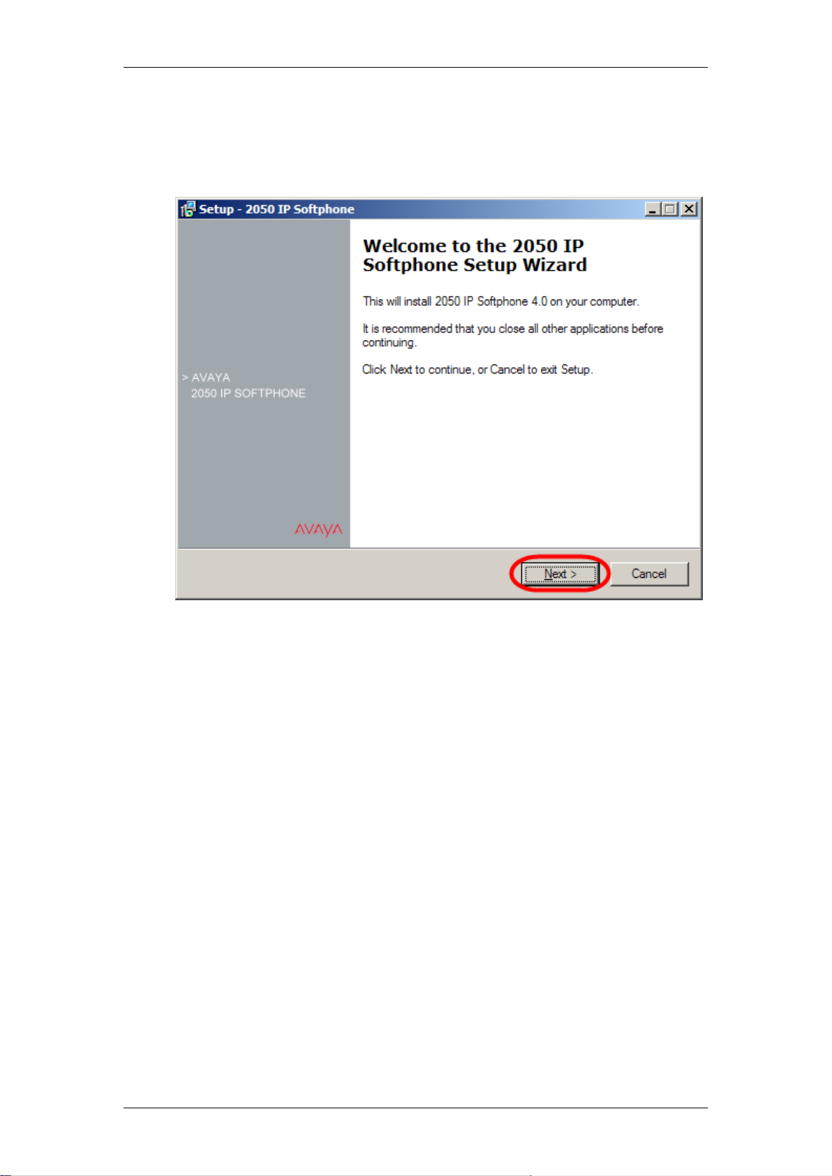
IP Telephony
4. Once the files have loaded the Install wizard screen will appear, click
Next.
NN40011-028 Issue 1.2 BCM Rls 6.0 53
Page 54

IP Telephony
5. Once you have read the licence agreement select the I accept the
terms in the licence agreement button. Click Next.
6. The next screen displays the default file location; though it is possible
to change the location if required by clicking on the Browse button.
Click Next.
54 NN40011-028 Issue 1.2 BCM Rls 6.0
Page 55

IP Telephony
7. You can now select or deselect the languages to be installed that can
be chosen when using the i2050. Make your selections and click Next.
8. Choose which Start Menu folder location you would like to launch to
2050 IP Softphone form, or accept the default location. Click Next.
NN40011-028 Issue 1.2 BCM Rls 6.0 55
Page 56

IP Telephony
9. Select which shortcuts you require for the 2050, and click Next.
10. Once all of the options needed to install have been selected, the
Ready to Install screen will appear. Click Install.
56 NN40011-028 Issue 1.2 BCM Rls 6.0
Page 57

IP Telephony
11. On completion click Install.
12. After a few moments you will be prompted to select a language for the
i2050 prompts and dialogs. The selectable options relate to the
languages selected/deselected earlier. Choose a language and click
Next.
NN40011-028 Issue 1.2 BCM Rls 6.0 57
Page 58

IP Telephony
13. Choose a theme for the main interface and click Next
14. Setup is now complete. Click Finish.
58 NN40011-028 Issue 1.2 BCM Rls 6.0
Page 59

IP Telephony
15. Once installation is complete, you will need to run the 2050 IP
Softphone Settings utility to assign a server address and to configure
audio peripherals. See the Configuring the 2050 IP Softphone
section of this guide.
16. If you have been supplied with the USB Audio Kit, plug that into the
USB port of your PC/laptop now. Once it has been connected, you can
select it as your audio device for 2050 usage.
Configuring the 2050 IP Softphone
Use the following procedure to configure the 2050 IP Softphone to connect to
the BCM.
1. On the Computer, click the Start button and then select Programs\
Avaya\2050 IP Softphone, and click on 2050 IP Softphone settings.
Or, if the IP Softphone has already been launched, click on the Avaya
logo, open the File menu and select Settings…
NN40011-028 Issue 1.2 BCM Rls 6.0 59
Page 60

IP Telephony
2. The IP Software Phone 2050 Settings utility will now be launched.
3. Click on the Server option to configure how the Softphone will connect
to the BCM:
a. If your site uses DHCP: Select the Automatic (DHCP) option.
Using DHCP is the default method of locating the call server. If
DHCP is used, no further configuration is required.
60 NN40011-028 Issue 1.2 BCM Rls 6.0
Page 61

IP Telephony
Attribute
Description
Headset or Handset
Microphone
Select the microphone used for making calls. Select USB Audio
Device.
Headset or Handset
Speaker
Select the speaker used for making calls. Select USB Audio Device.
Handsfree/
Paging/Ringing
Microphone
This is the microphone which is used when the handsfree device is
selected in the interface. This selection normally should match the
Avaya USB Audio Kit which enumerates as a USB Audio Device
Handsfree/
Paging/Ringing
Speaker
This is the speaker which is used when the handset free device is
selected in the interface. It is also the speaker which is used to play
ring tone and the device pages are directed. This selection normally
should match the PC's speakers. This allows ring tone and pages to
be heard over the PC speakers rather than on the headset
b. If you want to specify the server location manually, clear the
Automatic (DHCP) option. Select the Server type you wish to
configure: Primary, Secondary or Application.
i. Enter the IP address of the server.
Or
ii. Enter the Name of the server.
c. Select the Server Type as BCM
d. Ensure the Port number = 7000
4. Enter the number of Retries. If the initial connection fails, the 2050 will
attempt to re-connect the number of times indicated by Retries,
5. Then select either the OK or Apply button to confirm the configuration.
6. Select the tab for Sound Devices, and make sure the
Microphone/Speaker fields are configured for the USB headset kit (if
using). Then select either the OK or Apply button to confirm the
configuration.
NN40011-028 Issue 1.2 BCM Rls 6.0 61
Page 62

IP Telephony
Attribute
Description
Version
Shows the version of the USB Headset Adapter. Note: If the USB Headset
Adapter is not recognized or has a version number lower than 2.0 the
other features in this table are greyed out and unavailable.
Headset Type
Select the type of headset that you have connected to the USB Headset
Adapter.
Due to differences in headset construction, you may not get optimal audio
performance when using a headset that does not appear on the list. For
optimal performance, always use one of the headsets that appears on the
Headset Type drop list.
Manual Override
Select one of the available cadences to enable the Manual Override
feature. When Manual Override is enabled, you can manually turn on the
external lamp using the 2050 IP Softphone Smart Functions button on the
USB Headset Adapter. For more information about the 2050 IP Softphone
Smart Functions button, refer to the 2050 IP Softphone Help. Select None
to disable the Manual Override feature.
Headset
Disconnect,
Select one of the available cadences if you want the external lamp to
indicate when the headset is disconnected from the USB Headset
Adapter. Select None if you do not want the external lamp to indicate
when the headset is disconnected.
Active Call
Select one of the available cadences if you want the external lamp to
indicate when there is an active call on the IP Softphone 2050. If the USB
Headset Adapter is selected as the Ringing Speaker, the external lamp
also indicates when there is a call ringing on the IP Softphone 2050.
Select None if you do not want the external lamp to indicate when there is
an active call.
Note: If you select a cadence for Active Call, the external lamp also turns
on or flashes when another application uses the audio channel for the
USB Headset Adapter.
Message
Waiting
Select one of the available cadences if you want the external lamp to
indicate when the 2050 IP Softphone message waiting light is on. The
2050 IP Softphone message waiting light normally indicates when there is
a message waiting. However, most systems also turn on or flash the
message waiting light when the 2050 IP Softphone is ringing.
7. Further details regarding USB headset configuration can be viewed
from the USB Headset link.
62 NN40011-028 Issue 1.2 BCM Rls 6.0
Page 63

IP Telephony
Attribute
Description
Select None if you do not want the external lamp to indicate when the
message waiting light is on. Use backlight Select this check box to enable
the backlight for the USB Headset Adapter buttons. Clear this check box
to disable the backlight for the USB Headset Adapter buttons.
Note: When you enable the backlight, you can use the state of the
backlight to quickly determine if the 2050 IP Softphone is running. When
the backlight is on, the 2050 IP Softphone is running. When the backlight
is off, the 2050 IP Softphone is not running.
Configure Smart
Functions
Click this button to set the options that are available when you press the
Smart Functions button on the USB Headset Adapter.
Note: The External Lamp is an optional component. It normally is not included with the
USB Headset Adapter, and must be ordered separately. The external lamp also is known as
an “In-Use Indicator” lamp.
8. The 2050 IP Softphone will now require a licence. Refer to either the
Licensing the i2050 Using the BCM HTTP Server Method section of
this guide, or the Avaya document IP Phones Fundamentals
(NN43001-368) for Licensing Server or Node-Locked licensing
methods, dependant on which method is available for your system.
Licensing the i2050 Using the BCM HTTP Server Method
This method requires licenses to be generated on a per i2050 installation
basis.
1. In the 2050 IP Softphone Settings window, click on the Hardware ID
option, and make a note of the ID displayed. Send this to your keycode
supplier and request the licensing files.
NN40011-028 Issue 1.2 BCM Rls 6.0 63
Page 64

IP Telephony
2. Once you have obtained the licensing files they will need to be
uploaded to the BCM. In the Element Manager Configuration tab,
navigate to Resources, Telephony Resources, and click on IP Sets.
3. In the IP Terminal Global Settings tab of the Details area, click on the
Upload button at the bottom of the screen.
64 NN40011-028 Issue 1.2 BCM Rls 6.0
Page 65

IP Telephony
4. In the Import files window, click on Browse to locate the licensing files
obtained from your keycode supplier.
5. Select all the i2050 licensing files obtained from your keycode supplier,
and click on Select files.
6. Click OK to upload the files.
NN40011-028 Issue 1.2 BCM Rls 6.0 65
Page 66

IP Telephony
7. The files will be displayed in the IP clients configuration files area.
8. The i2050 now needs to be configured to search for the files on the
BCM. In the 2050 IP Softphone Settings window, click on the Server
option.
66 NN40011-028 Issue 1.2 BCM Rls 6.0
Page 67

IP Telephony
9. In the Provisioning Server field ensure the Protocol is set to HTTP
and that the URL field contains the location of the BCM. Click OK when
complete.
10. Continue with the Registering the 2050 IP Softphone section of this
guide.
Registering the 2050 IP Softphone
Use the following procedure to register your 2050 IP Softphone with the BCM.
1. Start the 2050 IP Softphone. The i2050 will attempt to find the licensing
information from the configured location. If licensing is successful, the
registration process can continue.
NN40011-028 Issue 1.2 BCM Rls 6.0 67
Page 68

IP Telephony
2. If a password prompt appears on the 2050 IP Softphone display, enter
the registration password (i.e. the Global Password described in the
Preparing your system for IP telephone registration section of this
guide) and press the OK soft key. You will need to use the dialpad on
the Softphone to enter the password.
3. Alternatively, you may be prompted to enter the following information:
a. Registration: SETNNA = 738662
b. Password: CONFIG = 266344
4. If a DN prompt appears on the 2050 IP Softphone display, enter the DN
you want assigned to this telephone, and press the OK soft key.
Otherwise, Auto-assign DNs will have been enabled in Element
Manager, and therefore the DN will automatically be applied.
68 NN40011-028 Issue 1.2 BCM Rls 6.0
Page 69

IP Telephony
5. After the registration is complete, you do not need to go through the
registration steps described above, unless you deregister the terminal.
Note: The 2050 IP Softphone Telephone can be configured as a standard
Digital handset. With this in mind, Lines and/or Line pool access require
configuration. For more information on these settings, please refer to the
Telephony Services Guide.
NN40011-028 Issue 1.2 BCM Rls 6.0 69
Page 70

IP Telephony
Using the 2050 IP Softphone
The default presentation of the 2050 Software phone is operational. In this
mode the user can operate most features available from the 1140e IP
Telephone.
Calls can be answered or made by pressing the green headset button. In this
mode the call server will select the line to answer or engage. The user can
also hang-up, hold, retrieve from hold, mute, adjust volume and access
network services such as voice mail.
The Number Pad provides a graphic keypad to dial numbers with a mouse. A
number can also be dialed by using the computer keyboard.
The display shows up to six line or feature keys provisioned for the set by the
BCM. The status of each line key on the display is illustrated by a graphic icon
(idle, ringing, connected, etc.). The line is labeled based on its BCM
provisioning information.
70 NN40011-028 Issue 1.2 BCM Rls 6.0
Page 71

IP Telephony
Below is a diagram showing the key components of the i2050 interface.
NN40011-028 Issue 1.2 BCM Rls 6.0 71
Page 72

IP Telephony
Additional options allow access to other features and functions.
72 NN40011-028 Issue 1.2 BCM Rls 6.0
Page 73

IP Telephony
The i2050 can also function in the System Tray of the Windows desktop.
Software Expansion Module
The 2050 IP Softphone provides a Software Expansion Module in case extra
feature or autodial buttons are required. An extra 54 buttons are available,
and can be configured by using the usual button programming features via the
interface, or under Element Manager programming (Telephony, Sets, Active
Sets, Capabilities and Preferences tab, CAP/KIM Button Programming tab).
To monitor lines, the Software Expansion Module should be configured as a
CAP Assignment in Element Manager under Telephony, Global Settings, CAP
Assignment.
NN40011-028 Issue 1.2 BCM Rls 6.0 73
Page 74

IP Telephony
To display the Software Expansion Module, click on the logo, navigate to
View, and then select Expansion Module.
The Software Expansion Module will load, and display the buttons‟
functions/features as programmed. Use the scroll bar to view and locate all
the buttons.
Incoming Call and Disconnect Popup
Calls ringing on the 2050 IP Softphone now generate a popup window
containing basic call information and call control options. This feature is
especially useful if the i2050 is minimised or operational in the System Tray.
74 NN40011-028 Issue 1.2 BCM Rls 6.0
Page 75

IP Telephony
The Popup window behaviour is determined in the Notifications area of the
2050 IP Softphone Settings options.
Incoming calls generate a call popup window in the lower right corner of youir
windows desktop. The call can be answered from the popup window, or the
i2050 interface can be launched by clicking on the Open button.
NN40011-028 Issue 1.2 BCM Rls 6.0 75
Page 76

IP Telephony
When the call is ended by either party, the Call Disconnected display will be
shown. Again, this popup window will display if the i2050 is minimised or
operating tin the Windows System Tray.
IP Terminal Features
The IP telephony sets and the 2050 IP Softphone can access the same
telephone features available on standard TDM sets, with the exception of
Voice Call.
In addition, the IP telephones have three additional IP-specific features:
Feature List: allows specification of the features that appear in the
Features List on the IP phones.
Key Labels: this feature allows labels for programmed buttons on the IP
phones to be specified.
Hot Desking: a user can use assume control of an IP phone in a
different location as if they were using their own phone at their usual
workplace.
Feature List
You can add and modify the features that display on the IP telephone feature
list, which is accessed through the Services button or by using FEATURE
*900.
The Feature Codes Guide provides a complete list of BCM Features and
index codes.
1. In the Element Manager, open the Configuration tab, followed by
Telephony, then Global Settings, and click on IP Terminal Features.
76 NN40011-028 Issue 1.2 BCM Rls 6.0
Page 77

IP Telephony
2. Click on the Features list tab. This will now display the list of features
already configured (12 features are assigned as default).
3. If you want to add a new feature to the list, click Add. Enter the name
of the feature and the associated feature code.
4. Feature codes can be deleted from the list, or the order changed by
selecting the feature and clicking Up or Down.
NN40011-028 Issue 1.2 BCM Rls 6.0 77
Page 78

IP Telephony
Feature List IP Set Usage
The Feature List settings will appear on the handset.
1. On the IP handset, enter FEATURE *900 or press the Services button.
2. Use the Page+ and Page- display keys to scroll to the feature you
want.
3. Use the navigation keys to move through the selections on the menu,
and when having made the choice, press Select.
Key Labels
This feature enables the labeling of buttons programmed on the IP phones.
For example, if you have a button programmed to F904, the button on the
display can be labeled as CC Login, CC In/Out etc.
1. In the Element Manager, open the Configuration tab, followed by
Telephony, then Global Settings, and click on IP Terminal Features.
2. Click on the Key Labels tab.
78 NN40011-028 Issue 1.2 BCM Rls 6.0
Page 79

IP Telephony
3. Double-click in the Key Label field that you want to re-label, and enter a
new description. Press the tab key to accept the change.
Hot Desking
The Hot Desking feature allows a user to divert calls and signals from one IP
telephone to another. For example, if a user is temporarily working in another
office, they can retain their telephone number by hot desking their usual
telephone to the IP telephone in their temporary office.
Hot desking can be accessed using FEATURE *999 on the telephone to
which the traffic will be diverted. The user can also evoke this feature from the
Services key menu, where it is defaulted as the first item on the list.
Hot desking must be allowed on the originating telephone and you need to
specify a password. These settings are found under the ADMIN key within the
hot desking feature. Hot desking is invoked through the DIVERT key within
the hot desking feature.
If the originating telephone does not have hot desking allowed, the user will
receive a Not Allowed prompt, indicating that the telephone is not available
for hot desking. This prompt also occurs if the originating telephone is on a
call when the diversion command was issued.
Once hot desking occurs between two IP telephones, no activity is allowed on
the originating telephone, except to cancel hot desking. The display on the
originating telephone indicates where it has been diverted. On the diversion
telephone, the key displays will reflect the displays from the originating
telephone.
Call forwarding to voice mail continues as normal. Voice mail can be
accessed from the active IP telephone, as if it were the originating telephone.
When hot desking is cancelled, this can be performed from either telephone,
the displays for each telephone return to normal. If you forget the password,
hot desking can only be cancelled from the originating set.
NN40011-028 Issue 1.2 BCM Rls 6.0 79
Page 80

IP Telephony
Note: When you cancel hot desking, ensure that the telephone is on-hook. If
you have just hung up, wait 10 seconds before attempting to cancel hot
desking.
Use the following procedure to set up a password and activate the feature on
the originating IP handset:
1. Enter FEATURE *999.
2. Press ADMIN.
3. Enter a new password, or change an existing password, and press OK.
4. Confirm the password, and press OK.
5. Allow/disallow hot desking, as required by pressing CHANGE.
6. Press QUIT to exit.
Using hot desking:
1. At the telephone you will be using to answer diverted calls, enter
FEATURE *999 or access the hot desking feature by pressing the
services key and selecting from the feature display list.
2. Press the soft key under the displayed DIVERT.
3. Enter the DN (extension number) of the telephone you want to divert to
this telephone.
4. Enter the password of the diverted telephone.
The buttons on your telephone will mimic the buttons on the diverted set. The
diverted telephone indicates that it has been diverted, and it cannot be used
until hot desking is cancelled.
Cancel hot desking
You can cancel hot desking from either telephone. Ensure that the telephone
is on-hook before canceling hot desking.
From the diverted telephone, press the soft key under the display of a
CANCEL prompt.
OR, on the live telephone:
1. Access FEATURE *999 or access the hot desking feature by pressing
the services key and selecting from the feature display list.
2. Enter the password of the diverted telephone.
80 NN40011-028 Issue 1.2 BCM Rls 6.0
Page 81

IP Telephony
3. Press the soft key under the display of a CANCEL prompt.
Keeping Call Forward Settings when IP Phones are
Disconnected
IP Phones can easily be relocated from one place to another. This will involve
them being disconnected from the BCM. Similarly, the 2050 IP Softphone will
be disconnected from the BCM due to its host PC/laptop being rebooted or
shutdown.
The Keep DN Alive feature allows any configured call forward rules to apply,
even when the set/Softphone is disconnected. This means that calls can still
be routed to voicemail even when the IP DN is disconnected.
Use the following procedure to configure set the Keep DN Alive feature.
1. In Element Manager Configuration tab, navigate to Telephony, Sets,
Active Sets and select the IP phone you want to configure.
NN40011-028 Issue 1.2 BCM Rls 6.0 81
Page 82

IP Telephony
2. Select the Capabilities and Preferences tab, followed by the IP
Terminals tab in the details section.
3. Select or de-select the Keep DN Alive checkbox to enable or disable
this feature. Enabling this feature will ensure that Call Forward rules will
still apply, even when the IP phone is disconnected from the BCM.
4. It is also possible to reset the Hotdesking password, force a firmware
download, and deregister the DN from this area.
5. Codecs can also be specified on an individual DN basis, overriding the
general IP phone codec settings for specific situations.
82 NN40011-028 Issue 1.2 BCM Rls 6.0
Page 83

IP Telephony
VoIP Gateways
With a VoIP trunk, you can establish communications between a BCM and a
remote system across an IP network.
The BCM system supports SIP and H.323 trunk protocols. Both types of
trunks support connections to other BCMs, a central call server such as
Succession 1000/M, and trunk-based applications. SIP trunks support
connections to ITSPs for enhanced call routing capability.
SIP trunks and H.323 trunks are assigned to a single Pool, and the routing
decision to route calls via H.323 or SIP is made based on the routing modes
of the two services (Direct/Gatekeeper/Proxy) and the combined routing table.
If the BCM will only use one of the trunk protocols then only configure the
associated tabs, i.e. if the BCM will only utilise H.323 then the SIP-specific
settings do not require configuration.
Configuring the Local Gateway Settings
The VoIP trunk access point at each system is called a gateway. The gateway
to your system, the local gateway, determines how incoming and outgoing
calls will be handled.
The local gateway parameters define how the BCM allows call signalling
information to be directed through VoIP trunks. Call signalling establishes and
disconnects the calls.
NN40011-028 Issue 1.2 BCM Rls 6.0 83
Page 84

IP Telephony
Field
Value
Description
Forward
redirected
OLI
<check box>
If you select the check box, the OLI of an internal telephone is
forwarded over the VoIP trunk when a call is transferred to an
external number over the private VoIP network. If not selected,
the system forwards only the CLID of the transferred call.
Remote
capability
MWI
<check box>
If you select the check box, the system sends the telephone
name without going calls to the network.
Send name
display
<check box>
This setting must coordinate with the functionality of the
remote system that hosts the remote voice mail.
Ignore inband DTMF
in RTP
<check box>
If you select the check box, the BCM ignores audible in-band
DTMF tones received over VoIP trunks after the BCM
connects to the remote end of a locally hosted contact center
application or to a locally hosted CallPilot application, such as
auto attendant, voice mail, or IVR.
IP Trunks
These are general settings that relate to both H.323 and SIP trunks.
1. Open the Resources folder and followed by the IP Trunks folder. Click
the General option and then select the IP Trunks Settings tab.
2. Click on IP Trunk Settings and configure as required.
IP Trunks Settings
84 NN40011-028 Issue 1.2 BCM Rls 6.0
Page 85

IP Telephony
Field
Value
Description
Telephony Settings
Fallback to
circuitswitched
Enabled-All
Enabled-TDM
Disabled
Your choice determines how the system will handle calls if the IP
network cannot be used.
Enabled-All: All calls are rerouted over specified PSTN
trunks lines.
Enabled-TDM: All TDM (digital telephones) voice calls will
be rerouted over specified PSTN trunks lines.
Disabled: Calls will not be rerouted.
Default: Enabled-All
Note: Enabled-TDM-only enables fallback for calls originating on digital telephones. This is useful if your
IP telephones are connected remotely, on the public side of the BCM network, because PSTN fallback
is unlikely to result in better quality of service in that scenario
MCDN
protocol
None
SL1
CSE
Both these protocols require a keycode.
SL1: use this protocol only for BCM 2.5 systems
CSE: Use this protocol for BCM 3.0 and newer systems. This
protocol supports Meridian 1 IPT.
Otherwise, use None.
Gatekeeper
digits
<0-9>
If dialed digits match gatekeeper digits, the call is routed via H323
protocol.
If the digits do not match, the call is routed via SIP protocol.
Gatekeeper
<check box>
If selected, all dialed digits match gatekeeper digits and VoIP calls
H.323 Settings
1. Open the Resources folder and followed by the IP Trunks folder. Click
the H323 Trunking option.
2. Select the Settings tab and configure the H323 Settings as required.
H323 Settings
NN40011-028 Issue 1.2 BCM Rls 6.0 85
Page 86

IP Telephony
Field
Value
Description
wildcard
will be routed through the gatekeeper
Normal Route
Fallback To
None
Prime set
Select None or Prime set. If Prime set is selected and the outgoing IP
trunk leg of the call in a tandem scenario cannot be completed, the
call will terminate on the prime set for the line.
Default: None
Configuration (click on the Modify button to configure)
*Call signalling
Direct
Gatekeeper
Resolved
Gatekeeper
Routed
Gatekeeper
Routed no
RAS
Direct: call signalling information is passed directly between
endpoints. The remote gateway table in the Element Manager
defines a destination code (digits) for each remote system to direct
the calls for that system to route. In each system, the IP Terminals
and H.323 Terminals records map IP addresses to specific
telephones.
Gatekeeper Resolved: all call signalling occurs directly between
H.323 endpoints. This means that the gatekeeper resolves the phone
numbers into IP addresses, but the gatekeeper is not involved in call
signalling.
Gatekeeper Routed: uses a gatekeeper for call setup and control. In
this method, call signalling is directed through the gatekeeper.
Gatekeeper Routed no RAS: Use this setting for a NetCentrex
gatekeeper. With this setting, the system routes all calls through the
gatekeeper but does not use any of the gatekeeper Registration and
Admission Services (RAS).
Enable H245
tunnelling
<check box>
If Enabled, the VoIP Gateway tunnels H.245 messages within H.225.
The VoIP Gateway service must be restarted for a change to take
effect.
Default: Disabled.
Primary
Gatekeeper IP
<IP
address>
If Gatekeeper Routed, Gatekeeper Resolved or Gatekeeper Routed
no RAS are selected under Call Signalling, type the IP address of the
machine that is running the gatekeeper.
Backup
Gatekeeper(s)
<IP
address>,
NetCentrex gatekeeper does not support RAS, therefore, any backup
gatekeepers must be entered in this field.
Note: Gatekeepers that use RAS can provide a list of backup
gatekeepers for the end point to use in the event of the primary
gatekeeper failure.
If Gatekeeper Routed, Gatekeeper Resolved, or Gatekeeper Routed no RAS are selected under Call
Signaling, enter one or more alias names for the gateway
Alias Names
Alias names are comma delimited, and may be one of the following types:
E.164 - numeric identifier containing a digit in the range 0-9. Identified by the keyword
TEL: Example: the BCM is assigned an E.164 and an H323 Identifier: Alias Names:
TEL:76, NAME:bcm10.avaya.com
NPI-TON - also referred to as a PartyNumber alias. Similar to E164 except that the
keyword indicates the NPI (numbering plan identification), as well as the TON (type
of number). Identified by one of the following keywords: PUB (Public Unknown
Number); PRI (Private Unknown Number); UDP (Private Level 1 Regional Number
(UDP)); CDP (Private Local Number (CDP)).
H.323Identifier - alphanumeric strings representing names, e-mail addresses, etc.
Identified by the keyword NAME:
86 NN40011-028 Issue 1.2 BCM Rls 6.0
Page 87

IP Telephony
Field
Value
Description
Example: The BCM is assigned a public dialed number prefix of 76, a private CDP
number of 45, and an H323 Identifier alias: Alias Names: PUB:76, CDP:45,
NAME:bcm10.avaya.com
H.225 (Q.931) CallingPartyNumber (NetCentrex gatekeeper) - The NetCentrex
gatekeeper uses the H.225(Q.931) CallingPartyNumber to resolve the call originator
for billing purposes. This number must then contain a unique prefix, or location code
that is unique across all endpoints that are using the NetCentrex gatekeeper.
Identified by the keyword src:. Example for private networks: CDP alias = src:<DN>;
UDP alias = src:<LOC><DN>. Example for public network: src:<public OLI>
Note: E164 or NPI-TON alias types are commonly used since they fit into dialling
plans. A BCM alias list should not mix these types. Also, the type of alias used
should be consistent with the dialling plan configuration. Use the same alias naming
method on all BCMs within a network.
Configuration
note:
Network note: If your private network contains a Meridian 1-IPT, you cannot use
Radvision for a gatekeeper.
Modify Call Signaling Settings
Call signaling
port
0-65535
Default: 1720
This field allows you to set non-standard call signaling port for VoIP
applications that require special ports.
0 = The first available port is used.
Ensure that you do not select a port that has been assigned
elsewhere in the BCM. To ensure the port is not in use, run netstat-a
from the command line.
RAS port
0-65535
Default: 0
This field allows you to set a non-standard Registration and
Admission (RAS) port for VoIP applications that require special ports.
0 = The first available port is used.
Ensure that you do not select a port that has been assigned
elsewhere in the BCM. To ensure the port is not in use, run netstat-a
from the command line.
Registration TTL
(s)
Default: 60
seconds
This TimeToLive parameter specifies the intervals when the VoIP
gateway sends KeepAlive signals to the gatekeeper. The gatekeeper
can override this timer and send its own TimeToLive period.
Gatekeeper TTL
(s)
The actual time used by the gatekeeper for the registration process.
Status
<read-only>
Indicates if the device is online.
Modify
<button>
Click to modify the parameters.
Note: All active H.323 calls are dropped if these settings are
changed.
NN40011-028 Issue 1.2 BCM Rls 6.0 87
Page 88

IP Telephony
Field
Value
Description
Telephony Settings
Fallback to
circuitswitched
Enabled-All
Enabled-TDM
Disabled
Your choice determines how the system will handle calls if the IP
network cannot be used.
Enabled-All: All calls will be rerouted over specified PSTN trunks lines.
Enabled-TDM: All TDM (digital telephones) voice calls will be rerouted
over specified PSTN trunks lines.
Disabled: Calls will not be rerouted.
Default: Enabled-All
Dynamic
Payload
96 - 127
Default: 120
Set to 0 to disable RFC2833 functionality.
SIP Settings
Local
Domain
<alphanumeric>
Local domain of the SIP network.
Call
signaling
port
<numeric>
The listening port for the BCM.
Note: FEPS (Functional Endpoint Proxy Server) must be restarted if
this value is changed.
Default: 5060 . Select Modify to change the Call Signalling Port
SIP Settings
1. Open the Resources folder and followed by the IP Trunks folder. Click
the SIP Trunking option.
2. Click on the Global Settings tab and configure the SIP Settings as
required.
SIP Settings
88 NN40011-028 Issue 1.2 BCM Rls 6.0
Page 89

IP Telephony
Field
Value
Description
RTP Keep Alives
Scope
None
RTP
RTP-RTCP
This setting should be used if the BCM is behind a NAT
Router. The available options are:
None: RTP keep-alives are disabled.
RTP: If selected, keep-alive parameters are displayed. If initial
keep-alives are enabled, the BCM will send an RTP packet
when a dialog is established.
RTP-RTCP: If selected, keep-alive parameters are displayed. If
initial keep-alives are enabled, the BCM will send an RTP
packet and an RTCP packet when a dialog is established.
Status
Status
<read-only>
Indicates the status of the gateway.
H323 & SIP Media Parameters
The H323 and SIP Media Parameters tabs determine a number of local
system settings. These values need to be coordinated with the other systems
on the network to ensure that all features work consistently across the
network. Media parameters include setting:
• The order of preferred codecs
• Voice activity detection
• Jitter buffer size
• Codec payload size
• IP fax transmission availability on the network
NN40011-028 Issue 1.2 BCM Rls 6.0 89
Page 90

IP Telephony
Field
Value
Description
Preferred Codecs
Preferred Codecs
None
G.711-uLaw
G.711-aLaw
G.729
G.723
Select the Codecs in the order in which you want the system to attempt
to use them.
Performance note: Codecs on all networked BCMs must be consistent
to ensure that interacting features such as Transfer and Conference
work correctly.
Systems running BCM 3.5 or newer software allow codec negotiation
and renegotiation to accommodate inconsistencies in Codec settings
over VoIP trunks.
Settings
H323 Media Parameters
The H323 Media Parameters tab controls codec settings for H323 trunks.
1. Open the Resources folder and followed by the IP Trunks folder. Click
the H323 Trunking option. Select the Media Parameters tab
2. Configure the H323 Settings as required.
H323 Media Parameters
90 NN40011-028 Issue 1.2 BCM Rls 6.0
Page 91

IP Telephony
Field
Value
Description
Enable Voice Activity
Detection
<check box>
Voice activity detection, also known as silence suppression
identifies periods of silence in a conversation, and stops sending IP
speech packets during those periods. In a typical telephone
conversation, most of the conversation is half-duplex, meaning that
one person is speaking while the other is listening.
If voice activity detection is enabled, no voice packets are sent from
the listener end. This greatly reduces bandwidth requirements.
G.723.1 and G.729 support voice activity detection.
G.711 does not support voice activity detection.
Performance note: Voice activity detection on all networked BCMs
and IPT systems (VAD setting on IPT systems) must be consistent
to ensure that interacting features such as Transfer and Conference
work correctly. As well, the Payload size on the IPT must be set to
30ms.
Default: Disabled
Jitter buffer
Auto
None
Small
Medium
Large
Select the size of jitter buffer you want to allow for your system.
Default: Auto
G.729 payload size (ms)
10, 20, 30,
40, 50, 60
Default: 30
Set the maximum required payload size, per codec, for the VoIP
calls sent over H.323 trunks.
Note: Payload size can also be set for IP telephones.
G.723 payload size (ms)
30
G.711 payload size (ms
10, 20, 30,
40, 50, 60
Default: 30
Incremental payload size
<check box>
When enabled, the system advertises a variable payload size (40,
30, 20, 10 ms)
Enable T.38 fax
<check box>
Enabled: The system supports T.38 fax over IP.
Disabled: The system does not support T.38 fax over IP
Caution: Operations note: Fax tones that broadcast through a
telephone speaker may disrupt calls at other telephones using VoIP
trunks in the vicinity of the fax machine. Here are some suggestions
to minimize the possibility of your VoIP calls being dropped
because of fax tone interference:
Locate fax machine away from other telephones.
Turn the speaker volume on the fax machine to the lowest level, or
off, if that option is available.
Force G.711 for 3.1k Audio
<check box>
When enabled, the system forces the VoIP trunk to use the G.711
codec for 3.1k audio signals such as modem or TTY machines.
Note: This setting can also be used for fax machines if T.38 fax is
not enabled on the trunk
NN40011-028 Issue 1.2 BCM Rls 6.0 91
Page 92
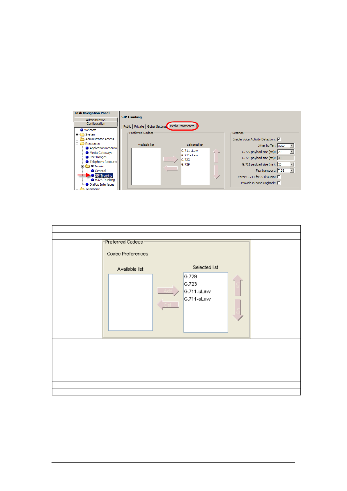
IP Telephony
Field
Value
Description
Preferred Codecs
Preferred
Codecs
None
G.711uLaw
G.711aLaw
G.729
G.723
Select the Codecs in the order in which you want the system to attempt to
use them.
Performance note: Codecs on all networked BCMs should be consistent
to ensure that interacting features such as Transfer and Conference work
correctly.
Note: The G.723 protocol can be used between IP endpoints
Field
Value
Description
Settings
SIP Media Parameters
SIP trunks are administered separately from H.323 trunks. It is common for
H.323 and SIP trunks to both exist on the same system; however, each has
different network segments.
1. Open the Resources folder and followed by the IP Trunks folder. Click
the SIP Trunking option. Select the Media Parameters tab.
2. Configure the SIP Settings as required.
SIP Media Parameters Settings
92 NN40011-028 Issue 1.2 BCM Rls 6.0
Page 93

IP Telephony
Enable Voice
Activity
Detection
<check
box>
The voice activity detection (silence suppression) identifies periods of
silence in a conversation, and stops sending IP speech packets during
those periods. In a typical telephone conversation, most of the
conversation is half-duplex, meaning that one person is speaking while the
other is listening. Voice activity detection is enabled, no voice packets are
sent from the listener end. This greatly reduces bandwidth requirements.
G.723.1 and G.729 support silence suppression.
G.711 does not support silence suppression.
Performance note: voice activity detection on all networked BCMs and
IPT systems (VAD setting on IPT systems) must be consistent to ensure
that interacting features such as Transfer and Conference work correctly.
Default: Disabled
Jitter Buffer
Auto
None
Small
Medium
Large
Select the size of jitter buffer you want to allow for your system.
G.729
Payload Size
(ms)
10, 20,
30, 40,
50, 60
Set the desired payload size, per codec, for the VoIP calls sent over SIP
trunks.
Note: Payload size can also be set for IP telephones.
G.723
Payload Size
(ms)
30
G.711
Payload Size
(ms)
10, 20,
30, 40,
50, 60
Default:
30
Fax Transport
<drop
down
list>
T.38
G.711
Default:
T.38
T.38: The system exclusively supports T.38 fax over IP.
G.711: The system exclusively supports G.711 fax over IP.
Force G.711
for 3.1k Audio
<check
box>
When enabled, the system forces the VoIP trunk to use the G.711 codec
for 3.1k audio signals such as modem or TTY machines.
Note: This setting can also be used for fax machines if T.38 fax is not
enabled on the trunk
NN40011-028 Issue 1.2 BCM Rls 6.0 93
Page 94
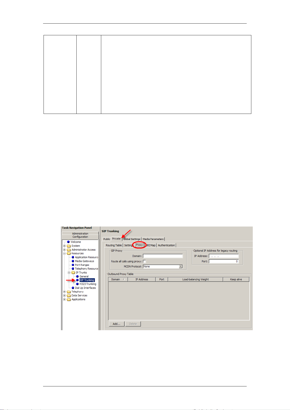
IP Telephony
Provide inband
ringback
<check
box>
This setting affects in-bound SIP trunk calls. If you select the check
box, the BCM attempts to stream ringback, tones, or
announcements in-band to the caller using RTP.
This setting results in in-band ringback.
It can be useful in tandem scenarios to transfer DTMF if the final
leg in the tandem connects to an IVR that plays announcements
before connecting the call.
Attention: Fax tones that broadcast through a telephone speaker
may disrupt calls at other telephones using VoIP trunks in the
vicinity of the fax machine. Here are some suggestions to minimize
the possibility of your VoIP calls being dropped because of fax tone
interference: Locate the fax machine away from other telephones.
Turn the speaker volume on the fax machine to the lowest level, or
off, if that option is available.
Private SIP Specific Configuration
The following sections relate specifically to SIP configuration over private
domains.
SIP Proxy
Allows the routing of calls through a configured SIP Proxy. The SIP Proxy‟s
domain and Outbound Proxy Tables can be configured as outlined below.
1. Open the Resources folder and followed by the IP Trunks folder. Click
the SIP Trunking option. Select the Private tab.
2. Select the Proxy tab and configure the Private SIP Proxy Settings as
required.
94 NN40011-028 Issue 1.2 BCM Rls 6.0
Page 95

Private SIP Proxy Settings
Field
Value
Description
SIP Proxy
Domain
<alphanumeric>
The name of the SIP Domain. This attribute is mandatory
Route all calls
using proxy
<check box>
Default:
unchecked
If unchecked, the system first checks the routing table before
routing all SIP calls.
If checked, the system uses the SIP Proxy for all SIP calls.
MCDN
Protocol
None
CSE
Default: None
Use CSE for interop with other devices (BCM or CS1K).
Optional IP Address for legacy routing
IP Address
Format 0.0.0.0
<7-24>
This attribute is optional.
The system uses the IP Address and Port to route the message if
the Outbound Proxy is not configured.
The IP Address and Port are used in message headers. If
supplied, the IP Address is used in the "maddr=" section of
message headers
The system uses these attributes for interop with NRS.
Port
<numeric>
Default: 0
This attribute is optional.
If the port is 0, the system uses the well-known SIP port 5060.
Otherwise, the system uses the port you enter here.
Outbound Proxy Table
Name
<alphanumeric>
The Name must be unique.
If the name you enter is a Fully Qualified Domain Name, DNS
resolves the address and the IP address can be left empty.
IP Address
Format 0.0.0.0
<7-24>
If you specify the IP Address, this address is used directly (the
system does not use the Name attribute and does not invoke
DNS).
If you leave this attribute empty, the system uses the Name
attribute.
Port
<0-65535>
Default: 0
If you leave Port as 0, the system uses the well-known SIP port
5060. Otherwise, the system uses the Port number you specify
here.
IP Telephony
NN40011-028 Issue 1.2 BCM Rls 6.0 95
Page 96

IP Telephony
Loadbalancing
Weight
<0-10>
Default: 1
Enter the load-balancing weight. The system uses this attribute to
distribute calls among the outbound proxies.
Keep alive
None
OPTIONS
Default: None
This attribute helps the system determine if an Outbound proxy
device is responding.
If you select None, the system does not ping the device, assuming
the device is always active.
If you select OPTIONS, the system sends a periodic OPTIONS
message to the Outbound Proxy. If the proxy fails to respond, the
system skips over it until it responds again
SIP Domain Names
Value
Description
e.164 / National
national.e164
String to use in phone context to identify
numbering plan type
e.164 / Subscriber
subscriber.e164
String to use in phone context to identify
numbering plan type
e.164 / Unknown
unknown.e164
String to use in phone context to identify
numbering plan type
SIP URI Map
SIP URI Map
Use the SIP URI Map to configure the sub-domain name associated with each
SIP URI (Session Initiated Protocol Uniform Resource Identifier). These
strings must be coordinated with the other nodes in the network.
These fields correspond to Public Network, Private Network, and Routing
settings of the Configuration > Telephony > Dialing Plan section of
Element Manager.
1. Open the Resources folder and followed by the IP Trunks folder. Click
the SIP Trunking option. Select the Private tab.
2. Click on the URI Map tab and configure the URI Map settings as
required.
Private SIP URI Map Settings
96 NN40011-028 Issue 1.2 BCM Rls 6.0
Page 97

IP Telephony
SIP Domain Names
Value
Description
e.164 / Special
special.e164
String to use in phone context to identify
numbering plan type
Private / UDP
UDP
String to use in phone context to identify
numbering plan type
Private / CDP
CDP
String to use in phone context to identify
numbering plan type
Private / Special
special.private
String to use in phone context to identify
numbering plan type
Private / Unknown
unknown.private
String to use in phone context to identify
numbering plan type
Private / Subscriber
Subscriber.private
String to use in phone context to identify
numbering plan type
Unknown / Unknown
unknown
String to use in phone context to identify
numbering plan type
SIP Authentication
These settings ensure that only the gateways that have been authenticated i.e
have valid credentials, can place calls to the BCM. If challenged, the BCM can
also provide its own valid credentials on outgoing calls.
1. Open the Resources folder and followed by the IP Trunks folder. Click
the SIP Trunking option. Select the Private tab.
2. Click on the Authentication tab and configure the SIP Authentication
settings as required.
NN40011-028 Issue 1.2 BCM Rls 6.0 97
Page 98

IP Telephony
Field
Value
Description
User Accounts
Description
<alphanumeric>
An optional description of the user account.
Domain
<alphanumeric>
Remote domain name of the service. Can
be either FQDN or an IP address.
Parent
<checkbox>
If selected, indicates that the user account is
a parent account. Child accounts are
mapped to individual sets.
CLID
<alphanumeric>
If the account is a parent account, this field
is empty. If it is a child account, you can
enter CLID information to be displayed for
this account in this field.
SIP Username
<alphanumeric>
Provided to the administrator from the
service provider.
Auth Username
<alphanumeric>
The authentication username used in
authentication challenges. This parameter is
provided by the SIP service provider. The
authentication username can be different
than the SIP username.
Auth Password
<alphanumeric>
The authentication password.
CLID Override
<alphanumeric>
Overrides the Caller ID parameter for the
account. If not configured, the Caller ID of
the account is used.
Display name Override
<alphanumeric>
Overrides the Display Name in From Header
parameter for the account. If not configured,
Private SIP Authentication Settings
98 NN40011-028 Issue 1.2 BCM Rls 6.0
Page 99

IP Telephony
Field
Value
Description
the Display Name in From Header of the
account is used.
PAI CLID Override
<alphanumeric>
Overrides the Caller ID in P-AssertedIdentity parameter for the account. If not
configured, the PAI CLID of the account is
used.
PAI Display name Override
<alphanumeric>
Overrides the Display Name in PAI
parameter for the account. If not configured,
the PAI Display name of the account is
used.
Contact Override
<alphanumeric>
Used in cases where the SIP trunking
service provider constructs R-URI for
outgoing calls based on user part of contact
header in SIP registration requests. Since RUri in incoming SIP trunk calls is used to
determine received digits to match them to
target lines, this parameter can be useful to
control received digits for incoming calls.
Maddr in Contact
<checkbox>
Select the check box to include maddr in
contact for this account. When selected, this
overrides the System Wide settings for
Maddr in the Private SIP settings tab.
Local Domain Override
<alphanumeric>
This field overrides the system wide local
SIP domain for outgoing calls associated
with the SIP user account.
Registration
<checkbox>
Used in cases where the SIP trunking
service provider constructs R-URI for
outgoing calls based on user part of contact
header in SIP registration requests. Since RUri in incoming SIP trunk calls is used to
determine received digits to match them to
target lines, this parameter can be useful to
control received digits for incoming calls.
Local SIP Authentication
Local Authentication
<check box>
Default: unchecked
Checked: The BCM authenticates all incoming
calls.
Unchecked: The system does not authenticate
incoming calls.
Quality of Protection
Authentication only
Authentication and Integrity
Default: Authentication only
"Authentication only" results in authentication
username/password encryption.
"Authentication and Integrity" adds a whole
message integrity check.
Note: This option adds to security but may impact
NAT/firewall integration.
401 Reason
<alphanumeric>
Default: Unauthorized
This character string is sent out in authentication
challenges.
Local Accounts
NN40011-028 Issue 1.2 BCM Rls 6.0 99
Page 100

IP Telephony
Field
Value
Description
User Id
<alphanumeric>
The administrator supplies each remote domain
with a unique User ID/Password. If the local
system challenges incoming calls, the remote
system must provide the User ID/Password
combination.
Password
<alphanumeric>
The administrator supplies each remote domain
with a unique User ID/Password. If the local
system challenges incoming calls, the remote
system must provide the User ID/Password
combination.
Description
<alphanumeric>
Description of remote domain.
Remote Account Fields
Realm
<domain>
Remote domain name.
User ID
<alphanumeric>
User ID and Password are supplied by remote
domain. Local system responds with User
ID/Password if outgoing call is challenged by
remote domain.
Password
<alphanumeric>
User ID and Password are supplied by remote
domain. Local system responds with User
ID/Password if outgoing call is challenged by
remote domain.
Description
<alphanumeric>
Description of remote domain.
SIP Trunk Settings
These are general settings that relate to Private SIP trunks.
1. Open the Resources folder and followed by the IP Trunks folder. Click
the SIP Trunking option. Select the Private tab.
100 NN40011-028 Issue 1.2 BCM Rls 6.0
 Loading...